1
Service Manual
SD-32
Sampling Head
070–8269–01
Warning
The servicing instructions are for use by qualified
personnel only. To avoid personal injury, do not
perform any servicing unless you are qualified to
do so. Refer to the Safety Summary prior to performing service.
Please check for change information at the rear
of this manual.
First Printing: May 1993
"$) *.3425-&.4 -".5'"$452&% #9 &+42/.*8 )"3 " 3&2*", .5-#&2 /. " 0".&, *.3&24 /2 4"( /2 34"-0&% /. 4)&
$)"33*3 )& '*234 ,&44&2 *. 4)& 3&2*", .5-#&2 %&3*(."4&3 4)& $/5.429 /' -".5'"$452& )& ,"34 '*6& %*(*43 /' 4)&
3&2*", .5-#&2 "2& "33*(.&% 3&15&.4*",,9 ".% "2& 5.*15& 4/ &"$) *.3425-&.4 )/3& -".5'"$452&% *. 4)&
.*4&% 4"4&3 )"6& 3*8 5.*15& %*(*43 )& $/5.429 /' -".5'"$452& *3 *%&.4*'*&% "3 '/,,/73
&+42/.*8 .$ &"6&24/. 2&(/. &+42/.*8 .*4&% *.(%/- 4% /.%/.
/.9&+42/.*8 "0".
&+42/.*8 /,,".% &&2&.6&&. )& &4)&2,".%3
.3425-&.43 -".5'"$452&% '/2 &+42/.*8 #9 &84&2.", 6&.%/23 /543*%& 4)& .*4&% 4"4&3 "2& "33*(.&% " 47/ %*(*4
",0)" $/%& 4/ *%&.4*'9 4)& $/5.429 /' -".5'"$452& &( '/2 "0". '/2 /.( /.( '/2 32"&, &4$
&+42/.*8 .$ /8 &"6&24/. 2*.4&% *. /092*()4 E &+42/.*8 .$ ,, 2*()43 2&3&26&% &+42/.*8 02/%5$43 "2& $/6&2&% #9 ".%
'/2&*(. 0"4&.43 *335&% ".% 0&.%*.( )& '/,,/7*.( "2& 2&(*34&2&% 42"%&-"2+3 ! ".% :
WARRANTY
! " " " ! ! " " ! ! "
" ! ! " " ! " ! " " " " " " ! " "
! " THIS WARRANTY IS GIVEN BY TEKTRONIX WITH RESPECT TO THIS PRODUCT IN LIEU OF ANY OTHER
WARRANTIES, EXPRESSED OR IMPLIED. TEKTRONIX AND ITS VENDORS DISCLAIM ANY IMPLIED WARRANTIES OF
MERCHANTABILITY OR FITNESS FOR A PARTICULAR PURPOSE. TEKTRONIX' RESPONSIBILITY TO REPAIR OR
REPLACE DEFECTIVE PRODUCTS IS THE SOLE AND EXCLUSIVE REMEDY PROVIDED TO THE CUSTOMER FOR
BREACH OF THIS WARRANTY. TEKTRONIX AND ITS VENDORS WILL NOT BE LIABLE FOR ANY INDIRECT, SPECIAL,
INCIDENTAL, OR CONSEQUENTIAL DAMAGES IRRESPECTIVE OF WHETHER TEKTRONIX OR THE VENDOR HAS
ADVANCE NOTICE OF THE POSSIBILITY OF SUCH DAMAGES.
Table of Contents
List of Figures . . . . . . . . . . . . . . . . . . . . . . . . . . . . . . . . . . . . . . . . . . . . . . .
iii
List of Tables . . . . . . . . . . . . . . . . . . . . . . . . . . . . . . . . . . . . . . . . . . . . . . . .
v
General Information . . . . . . . . . . . . . . . . . . . . . . . . . . . . . . . . . . . . . . . . .
1Ć1
Introduction . . . . . . . . . . . . . . . . . . . . . . . . . . . . . . . . . . . . . . . . . . . . .
Safety Summary . . . . . . . . . . . . . . . . . . . . . . . . . . . . . . . . . . . . . . . . .
Installing and Removing the Sampling Head . . . . . . . . . . . . . . .
Packaging for Shipment . . . . . . . . . . . . . . . . . . . . . . . . . . . . . . . . . .
Operating Environment . . . . . . . . . . . . . . . . . . . . . . . . . . . . . . . . . . .
" "# 1Ć1
1Ć2
1Ć4
1Ć6
1Ć7
'
Checks and Adjustments . . . . . . . . . . . . . . . . . . . . . . . . . . . . . . . . . . . . .
2Ć1
Test Equipment . . . . . . . . . . . . . . . . . . . . . . . . . . . . . . . . . . . . . . . . . .
Using These Procedures . . . . . . . . . . . . . . . . . . . . . . . . . . . . . . . . .
$"! "! # "& " ""! # "! !# " #! "# #!" "! Procedure 1 PowerĆOn . . . . . . . . . . . . . . . . . . . . . . . . . . . . . . . . . . .
Procedure 2 Dot Transient Response . . . . . . . . . . . . . . . . . . . . . .
Procedure 3 Offset . . . . . . . . . . . . . . . . . . . . . . . . . . . . . . . . . . . . . . .
Procedure 4 Noise . . . . . . . . . . . . . . . . . . . . . . . . . . . . . . . . . . . . . . .
Procedure 5 Acquisition Aberrations . . . . . . . . . . . . . . . . . . . . . .
Procedure 6 Maximum Signal Voltage . . . . . . . . . . . . . . . . . . . . .
Procedure 7 Bandwidth . . . . . . . . . . . . . . . . . . . . . . . . . . . . . . . . . .
2Ć3
2Ć6
'
'
'
'
2Ć9
2Ć11
2Ć16
2Ć20
2Ć23
2Ć28
2Ć31
Maintenance . . . . . . . . . . . . . . . . . . . . . . . . . . . . . . . . . . . . . . . . . . . . . . . .
3Ć1
Preventive Maintenance . . . . . . . . . . . . . . . . . . . . . . . . . . . . . . . . . .
%" " ! ""'!"$ $ !!" 3Ć1
'
'
'
General Information
Checks and Adjustments
Maintenance
SDĆ32 Service Manual
i
Table of Contents
! "
"
"
Theory of Operation . . . . . . . . . . . . . . . . . . . . . . . . . . . . . . . . . . . . . . . . .
4Ć1
System Functional Overview . . . . . . . . . . . . . . . . . . . . . . . . . . . . . .
Loop Gain . . . . . . . . . . . . . . . . . . . . . . . . . . . . . . . . . . . . . . . . . . . . . . .
Offset Null . . . . . . . . . . . . . . . . . . . . . . . . . . . . . . . . . . . . . . . . . . . . . . .
4Ć1
4Ć2
4Ć3
Replaceable Parts . . . . . . . . . . . . . . . . . . . . . . . . . . . . . . . . . . . . . . . . . . .
5Ć1
Parts Ordering Information . . . . . . . . . . . . . . . . . . . . . . . . . . . . . . .
Using the Replaceable Parts List . . . . . . . . . . . . . . . . . . . . . . . . . .
5Ć1
5Ć2
Theory of Operation
Replaceable Parts
ii
Contents
List of Figures
#!-* 21&)%#'! (&)*,&',+ #' ' ' #!-* 21'+,%%#'! &)%#'! #' ' '+,*-&', #!-* 21(,#('+ ( (',*(%+ ' ('',(*+ (' #' *&
'+,*-&',+ #!-* 21&)%#'! *. (,#('+ #!-* 21 #& +(',*(%%* (* -&)* (,#(' #!-* 212 &)%#'! %($ #!*& #!-* 21#+)%0 *+ , *#(-+ (() #' ,,#'!+ #!-* 21/)%( #. ( ," 2 &)%#'! SDĆ32 Service Manual
2
2
2
2
2
2
2
2
iii
iv
List of Tables
SDĆ32 Service Manual
(#687#/1.#)#*0 ')'0/ *" ,#!'$'!0'+*/ (#687#/0 -1',)#*0 (#68
7 #..0'+* #/1.#)#*0 ')'0/ (#687(!1(0'+* +$ ",0#. +..#!0'+* 3),(# (1#/ (#687'%*( +1.!# #/,+*/# 55 3),(# (1#/
(#687'%*( +1.!# #/,+*/# 55
3),(# (1#/ (#6874/0#) #/,+*/# 55 3),(# (1#/ (#6874/0#) #/,+*/# 55 3),(# (1#/ (#687),('*% #" .#-1#*!4 &.!0#.'50'+*
55 3),(# (1#/ (#687),('*% #" .#-1#*!4 &.!0#.'50'+*
55 3),(# (1#/ (#687(!1(0'+* +$ ",0#. +..#!0'+* !0+./ (#687'%*( +1.!# #/,+*/# 5 5 (#68
7'%*( +1.!# #/,+*/# 5 5 (#6874/0#) #/,+*/# 5 5 (#6874/0#) #/,+*/# 5 5 (#687),('*% #" .#-1#*!4 &.!0#.'50'+*
5 5 (#687),('*% #" .#-1#*!4 &.!0#.'50'+*
5 5 (#6
87#(0'2# 1/!#,0' '('04 0+ (#!0.+/00'! '/!&.%# 8
8
8
8
8
8
8
8
8
8
8
8
8
8
8
8
8
8
v
vi
General Information
& &'"! )& ' !"% '"! ! '" ##+ #"*% '" ' -
#! '+ !"% '"! & * & !"% '"! "! !&'! ! % ")! '
& #! #! "% &# !' ! !)%"! !' "!'"!& &(
& "#%'! ' #%'(% & !( %
Introduction
& &! "% (& + $(
&%) #%&"!! ' "!'!& !"% '"! !&&%+ '" ! !'!
' - #! - #! & &!-!! , !*' & #!
' & &! "% (& ! ' ' %& ' #! &"&"#& ' - ('-!! !' ! ' %& "
(!'"!& ! !+,%&
SDĆ32 Service Manual
1Ć1
General Information
Safety Summary
" " $
! ! ! " " " $
"
Terms in Manuals
CAUTION " "
WARNING " " Terms on Equipment
CAUTION " # "
# " DANGER " # " $
Symbols in Manuals
Static Sensitive Devices
Symbols on Equipment
DANGER
High Voltage
Protective
ground (earth)
terminal
ATTENTION
Refer to
manual
Grounding the Instrument
! ! " ! $ " !" $
! Danger Arising from Loss of Ground
$ " 1Ć2
General Information
General Information
Do Not Operate in Explosive Atmospheres
SDĆ32 Service Manual
1Ć3
General Information
Installing and
Removing the
Sampling Head
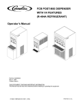
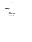
" (" &" & !%&$' !& %& & !%&$' !&% %)& &" "$ !%&! "$ $ "(! % #! , #! %% !&" & "! " & $"!& #! " #$&,
!&% " ! $% & #! %"%"# "$ $%
"
'!&"!% ! !*+$ '$ , %")% & $"!& #!% " &
!%&$' !&% ! & "&"!% " & % #! " #$& !&%
Sampling Head
Compartments
11801B
Sampling Head
Compartments
CSA 803A
Power Only Sampling
Head Compartments
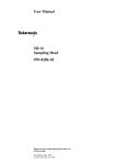
Figure 1Ć1:ăSampling Head Compartments in an 11801B and a
CSA 803A
1Ć4
General Information
General Information
# # "&# "# # # " !## "&' $" # &# ! !""$! # " " "# #$! # (& "!& # ## # " $! (
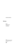
CAUTION
If the green indicator light remains on when the STANDBY position
is selected, then the switch has been left internally disabled after
the servicing of the power supply. To enable the ON/STANDBY
switch, refer to the Maintenance section of your instrument's SerĆ
vice Manual.
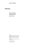
To avoid damage to the instrument, set the instrument's ON/
STANDBY switch to STANDBY before installing or removing a
sampling head.
!% # " ! "#!$# "# # "#!$#"
# $! # (& "!& # " # "(
# "&' $ $# # " !
LockĆDown
Screw
Sampling
Head
Figure 1Ć2:ăInstalling a Sampling Head in an Instrument
SDĆ32 Service Manual
1Ć5
General Information
Packaging for
Shipment
$#'' '* " &)' ( #&" &(#" " $" (# $
'!$ " +" '$$" ( - #!!& (&"'$#&((#"
(( ( (# ( '!$ " ( ' '$$ (# -#)& # (&#",
'&* "(& #& '&* #& &$& " ) ( # #+" "#&!(#" #" (
(
H
! " &'' # ( "'(&)!"( " '!$ " #+"&
H
! # $&'#" ( -#)& &! +# " #"(( #)( ( "'(&).
!"( " '!$ " H
#!$ ( "'(&)!"( " '!$ " (-$ " '& ")!&
H
'&$(#" # ( '&* &%)&
( '!$ " ' # #+' ( #&" $ ' "#( * .
#& ' "#( ( #& )'
ăStep 1:ă(( '#&(.&)( (&!"(#" (# ( '!$ " "$)(
ăStep 2:ă(" #&&)( &#& &(#" +( "' !"'#"' (
'( ', "' ! &(& (" ( '!$ " !"'#"'
' &(#" +( )&'(" ('( '(&"( # ( '( $#)"' $&
'%)&."
ăStep 3:ă) - +&$ ( '!$ " +( "(.'(( '(" #& ('
%)* "( (# $&#(( ( "'
ăStep 4:ă( - $ )"" #& )&(" #! (+" ( &(#" "
( '!$ " (# )'#" ( '!$ " #" '' #+
(& "' # $" #" '
ăStep 5:ă ( &(#" +( '$$" ($ #& +( ")'(& '($ '
ăStep 6:ă& ( &'' # ( (&#", '&* "(& " -#)& &()&"
&'' #" ( &(#" " #" #& !#& $&#!""( $ '
1Ć6
General Information
General Information
Operating
Environment
% $ " # "! $ " !# " ! Operating Temperature
" " ! % " " " "# ! "% _
_ " " ! " " "# ! _ " _ " !" " " "# ! #"! " "
"! % " !!! " " " " "# & % !# " # & $ " '#" % '# & " "! " Enhanced Accuracy # "
!" #" "! !# " " " "# ! " "_ " ! ! $ "
!" #"
SDĆ32 Service Manual
1Ć7
1Ć8
Checks and Adjustments
!+ +,!'& '&,!&+ (*'-*+ ,' # , +(!!,!'&+ & %+-*2
%&, $!%!,+ $!+, !& $ 2 (!!,!'& '* +-*%&, !%!, !+
$!+, , , !&&!& ' (*'-* + /$$ + (*'-*+ '&,!&
'&$0 # +,(+ +!& , 2 %($!& + &' !&,*&$ "-+,2
%&,+ (*,+ !& , !+ +,!'& (*'.! $'!$ +)-& ' #+ '*
(*'*%!& '%(* &+!. (*'*%& .*!!,!'& (*'-* ,' .*!0
, , , +%($!& %,+ +(!!,!'&+ ' -&,!'&$$0 ,+, , +%2
($!& (*'*% , (*,+ !& $2 / ! . 10+ !& , -&2
,!'&$ +, '$-%&
* ,' , %&-$ '* %'* !&'*%,!'& '-,
+(!!,!'&+ & +%($!& '(*,!'& * ,' $ 2 '* !&'*%2
,!'& '&*&!& ,+, )-!(%&, -+ !& , +,-(+
TableĂ2Ć1:ăMeasurement Limits and Specifications
Part and Description
Measurement
Limit
Specification
Functional
Test
*'-* '/*2&
&'&
&'&
0+
% /!, -,'%,!
$!*,!'&
v **'*
0+
% /!, -,'%,!
$!*,!'&
v **'*
&'
*'-* ', *&+!&,
+('&+
% /!, -$,
+,,!&+
" **'*
&'
" %
0+
*'-* +,
+,
+, & /!,
*(,!,!'& *,
" %
&'
%'', !& %
0+
%'', !& &
%
0+
*'-*
'!+
SDĆ32 Service Manual
2Ć1
Checks and Adjustments
TableĂ2Ć1:ăMeasurement Limits and Specifications (Cont.)
Part and Description
Measurement
Limit
Specification
)&,) (,"*"+"&%
))+"&%* -"+!
*&,)
2Ć2
Functional
Test
%&
+& '*
'* +& %*
%* +& %*
%* % ,'
%* +& '*
+& "
"
"
)&,) ."$,$
" %# &#+ ))+"&%*
&) 0 +'
$'#"+,
)&,) %-"+!
/
%&
"
%&
Checks and Adjustments
Checks and Adjustments
Test Equipment
Table 2Ć2 lists test equipment suggested for use with this manual. Procedure
steps are based on the test equipment examples given, but other equipment
with similar specifications may be substituted. Test results, setup informaĆ
tion, and related connectors and adapters may be altered by the use of
different equipment.
TableĂ2Ć2:ăTest Equipment
Description
Minimum
Specification
Examples of Applicable
Test Equipment
11800 Series
Oscilloscope or
CSA 803 Series
Communications
Signal Analyzer
Tektronix digital
sampling oscilloscope
Tektronix 11801/A/B, 11802
Digital Sampling Oscilloscope
Pulse Generator
1 ns rise time, 5 V
output, 10 Hz to
250 MHz frequency
range
Tektronix PG 502 Pulse
Generator with a TM 500
Series Power Module
Time Mark
Generator
1 ns through 5 s
markers in a 1-2-5
sequence, at least 5
parts in 10& accuracy
Tektronix TG 501A Time Mark
Generator with a TM 500
Series Power Module
Calibration
Generator
DC output, 0.5%
accuracy 1 V output
amplitude
Tektronix PG 506A Calibration
Generator with a TM 500
Series Power Module
Tektronix CSA 803, CSA 803A
Communications Signal
Analyzer
Calibration Step
Generator
SDĆ32 Service Manual
Tektronix 067-1338-0X
Calibration Step Generator
(where X represents either a
0, 1, 2, 3, 5, or 6; depending
on the power supply appropriĆ
ate for your country. Refer to
Section 5, )
Frequency
Synthesizer
50 MHz to 40 GHz
Output adjustable to
+2 dBm, with LF
reference output
Wiltron 6769B
Sweep
Generator
40 GHz to 50 GHz
Output adjustable to
0 dBm
Wiltron 6672B
Waveguide
Coupler
WRĆ19, 10 dB
Aerowave 19Ć3000/10
Waveguide
Detector
WRĆ19, 40-50 GHz
Pacific Millimeter Products
Model UD
2Ć3
Checks and Adjustments
TableĂ2Ć2:ăTest Equipment (Cont.)
Description
Minimum
Specification
Examples of Applicable
Test Equipment
System
Controller
Any compatible
controller with MS DOS
and a serial port
configured for COM1
IBM compatible PC with
terminal emulation software
Power Meter
50 GHz bandwidth
HP 437B
Power Sensor
50 GHz bandwidth
HP 8487A
RF Cable
12Ćinch; SMA
connectors
Tektronix Part 174-1364-00
Serial Cable
10Ćft RSĆ232ĆC Cable
Tektronix Part 012-0911-00
Sampling Head
Extender
Tektronix Part 012-1220-00
Coaxial Cable or
Adapter
Semirigid, 6Ćinch with
2.9 mm connectors or
2.9 mm MM Adapter.
Cable:
Tektronix Part 015-0564-00
Adapter:
Tektronix Part 015-0613-00
Adapter, KM to
VM
KM to VM
Wiltron 34VK50
Adapter, WR19
Waveguide to
VM
WR19 Waveguide to
VM
Wiltron 35WR19V
Adapter, VF to
VF
VF to VF, characterized
Wiltron SC4193
Adapter
Characterized FF
2.4 mm to 2.9 mm
Tektronix Part 015-0615Ć00
Adapter, SMA to
BNC (4 required)
SMA male to BNC
female
Tektronix Part 015-0554-00
Adapter, K or
SMA F to V or
2.4 mm M *
2Ć4
Tektronix Part 011-0157-00
(furnished with SDĆ32)
10 dB Attenuator
50 GHz bandwidth,
one male and
one female V
Wiltron 41V-10
Attenuator, 5X
14 dB attenuation,
50 W, one male and
one female BNC
Tektronix Part 011-0060-02
Attenuator, 2X
6 dB attenuation, 50 W,
one male and one
female BNC
Tektronix Part 011-0069-02
Checks and Adjustments
Checks and Adjustments
TableĂ2Ć2:ăTest Equipment (Cont.)
Description
Minimum
Specification
Examples of Applicable
Test Equipment
W
$/*'+ 1',+
",++$"1,/
*-$# +"$ W * )$ ",++$"1,/
$(1/,+'5 /1 W
$/*'+ 1',+
",++$"1,/0
*-$# +"$ W ",++$"1,/0
$(1/,+'5 /1 &,/1 '/"2'1
$/*'+ 1',+
)$ ",++$"1,/
$(1/,+'5 /1 %2/+'0&$# 4'1& 7
!)$0
/$.2'/$#
I ",++$"1,/0
$(1/,+'5 /1 /'01 1/ -
$(1/,+'5 /1 1 1'" ,+1/,)
1
$(1/,+'5 /1 $$#)$7+,0$
-)'$/0
,6'#/'3 "/$47
#/'3$/
1'-
,/.2$ 4/$+"&
I '+7)!
))$+ 4/$+"&
I
* The 2.4 mm connector on the SDĆ32 will mate with either 2.4 mm or type V connectors.
Types K and SMA also can be interconnected.
SDĆ32 Service Manual
2Ć5
Checks and Adjustments
Using These
Procedures
&(%+( $) -* )*+& ""+)*(*%$ ** )%-) * *)* '+&1
#$* $ %- *% %$$* * ( *% " 1 %( .#&") % * *)*
'+&#$* %( &(%+(
Conventions in this Manual
$ *) &(%+() * %""%-$ %$,$*%$) ( +)
H
"**() -*$ * %/ % *.* $*/ (%$* &$" %$*(%")
$*%() $ %$$*%() %( .#&" %$ * $)*(+#$*
$ )#&"$ H
Bold "**() $*/ #$+ "") $ )&"/ #)))
H
$*" &*" "**() $*/ %$$*%() %$*(%") $ $*%() %(
.#&" %)*%$ %$ ))%* *)* '+&#$* $*" &*" "**()
")% $*/ +)*#$*) $) * )#&"$ $ )%# )*&) * ()* -%( ) *"0 *% $*/ )*& ** %$*$) &(%(#$ ,(*%$ %( $ +)*#$* $)*(+*%$ %( .#&" Check
) * ()* -%( $ * **" % )*& $ "*(" )&*%$ ) ! Adjust &&() $ * **" * )*& $,%",) $ "*(" +)*#$* Examine ) * ()* -%( $ * **" * )*& %$($) #)+(#$* "#*)
** $* -*( * )#&"$ ) %&(*$ &(%&("/ *) "#*)
( $%* *% $*(&(* ) "*(" )&*%$)
Initialized and Stored Settings
* * $$$ % #%)* )*&) /%+ ( $)*(+* *% Initialize * $)*(+1
#$* ) &(* % * )*+& Initialize *+( ,"" *(%+ *
#$+ &()*) "" $)*(+#$* %$*(%") $ +$*%$) *% !$%-$ ,"1
+) $*"0$ * $)*(+#$* * * $$$ % )*& "#$*) *
&%))"*/ % )**$) (%# &(,%+) &(%+() +)$ ((%$%+) %( %$1
+)$ ()+"*)
Menu Selections and Measurement Techniques
*") %$ #)+(#$* *$'+) $ $)*(+*%$) %( #!$ #$+
)"*%$) ( $(""/ $%* $"+ $ *) #$+" %#&($), 1
)(&*%$) % #$+) $ $)*(+#$* *+() ( "%* $ * User Manual
%( /%+( $)*(+#$* $ $ * SDĆ32 Sampling Head User Manual
2Ć6
Checks and Adjustments
Checks and Adjustments
Setup Illustrations
% %# ) $ "# $ ! # # !# " $
"# %$ # )*"# # $ " #$"%,
$ $# !" %"# +" #$"%$ # # ' !" %"
$ ($ $ $ "# ) %" " #$"%$
) " " $$ # ' $ %#$"$ !"$%" $ # # ! "# %$ #
)*"# & ) $' #! !"$$# # !"
$ %" $ "# # # !# $ # $" # ,
$ "# #$"%$ " # ' %" ,
SDĆ32 Service Manual
2Ć7
Checks and Adjustments
11801
Left Sampling Head
Compartment
Calibrator Output
Trigger Input
Internal Clock Output
11802
Left Sampling Head
Compartment
Calibrator Output
Trigger Input
Internal Clock Output
11801A and 11801B
Left Sampling Head
Compartment
Calibrator Output
Antistatic Connection
Trigger Input
Internal Clock Output
CSA 803 and CSA 803A
Left Sampling Head
Compartment
Calibrator Output
Antistatic Connection
Trigger Inputs
Internal Clock Output
Figure 2Ć1:ăLocations of Controls and Connectors on Mainframe Instruments
2Ć8
Checks and Adjustments
Checks and Adjustments
Procedure 1
PowerĆOn
"-#*-( /%&. +-* "!0-" 1&/%&) /%" (&")/ /"(+"-/0-" -)$" *# _ /*
_
Setup to PowerĆOn
11801B
Sampling
Head
CSA 803A
Sampling
Head
Procedure to PowerĆOn
ăStep 1:ă"/ /%" #*''*1&)$ &) /%" *-!"- '&./"!
(+'&)$ "!
*/ &)./''"! 2"/
)./-0(")/ &)#-("
.1&/ % ăStep 2:ă)./'' /%" 3 .(+'&)$ %"! &) /%" '"#/ .(+'&)$ %"!
*(+-/(")/
ăStep 3:ă&/% /%" &)./-0(")/. -"- +)"' ."/ /* *))" / /%" &)./-0(")/ /* .0&/'" +*1"- .*0- "
ăStep 4:ă"/ /%" -"- +)"' /* )! /%")
/%" &)./-0(")/. #-*)/ +)"' .1&/ % /* %") /%" &)./-0(")/ &. #&-./ &)./''"! /%" -"- +)"' .%*0'! " ."/ /* )! -"(&) &) /%" +*.&/&*) %") 0." /%"
#-*)/ +)"' .1&/ % /* +"-#*-( '' .0.",0")/ +*1".1&/ %&)$
SDĆ32 Service Manual
2Ć9
Checks and Adjustments
ăStep 5:ă # #
2Ć10
H
H
H
! !"
H
H
H
H
Checks and Adjustments
Checks and Adjustments
Procedure 2
Dot Transient
Response
"
! Measurement Limits
H
v H
" Setup to Check Dot Transient Response
2.4mmĆSMA SMAĆBNC
Adapter
Adapter
5X Attenuator
11801B
Pulse
Generator
Internal Clock Output
SMAĆBNC Adapter
2X Attenuator
(not connected yet)
2.4mmĆSMA SMAĆBNC
Adapter
Adapter
5X Attenuator
CSA 803A
Pulse
Generator
Internal Clock Output
SMAĆBNC Adapter
SDĆ32 Service Manual
2X Attenuator
(not connected yet)
2Ć11
Checks and Adjustments
Procedure to Check Dot Transient Response
ăStep 1:ăInitialize the instrument settings, then make the following setĆ
tings in the order listed:
Sampling Head
CH 1 SELECT CHANNEL On/Off . . . . . . . . . . . . . . . . . . . . . . . . . . On
Instrument Mainframe
Vertical (Ă Ă) icon . . . . . . . . . . . . . . . . . . . . . . . . . . . . . . . . . . . . . . press
Vert Size: M1 . . . . . . . . . . . . . . . . . . . . . . . . . . . . . . . . 50 mV/division
TRIGGER button . . . . . . . . . . . . . . . . . . . . . . . . . . . . . . . . . . . . . . press
Source . . . . . . . . . . . . . . . . . . . . . . . . . . . . . . . . . . Internal Clock
Horizontal (Ă Ă) icon . . . . . . . . . . . . . . . . . . . . . . . . . . . . . . . . . . press
Main Pos . . . . . . . . . . . . . . . . . . . . . . . . . . . . . . . . . . . . . . . . . . . press
Set to Min . . . . . . . . . . . . . . . . . . . . . . . . . . . . . . . . . . . . . . . press
Main Size . . . . . . . . . . . . . . . . . . . . . . . . . . . . . . . . . . . . 20 ns/division
Pulse Generator
Back Terminator button . . . . . . . . . . . . . . . . . . . . . . . . . . . . . . pull out
Period . . . . . . . . . . . . . . . . . . . . . . . . . . . . . . . . . . . . . . External Trigger
Duration . . . . . . . . . . . . . . . . . . . . . . . . . . . . . . . . . . . . . . . square wave
Examine dot response at 250 mV with automatic calibration setĆ
tings Ċ by performing Steps 2 through 31.
ăStep 2:ăSet the pulse generator's amplitude for a level of 375 mV peakĆ
peak observed on the instrument screen.
ăStep 3:ăSet the Vert Offset: MI so that the step is approximately cenĆ
tered on the screen.
ăStep 4:ăPress the UTILITY button and touch Enhanced Accuracy
(11801A/B and CSA 803 Series) or press the ENHANCED ACCURACY
button (11801/2).
ăStep 5:ăTouch Loop Gain and then the channel number you are using.
ăStep 6:ăTouch Automatic Calibrate. Ignore message at top of screen
regarding connection of calibrator output. Then touch Proceed.
ăStep 7:ăTouch Exit.
ăStep 8:ăSet the pulse generator's amplitude for a 250 mV peakĆpeak
display.
ăStep 9:ăPress the WAVEFORM button and then touch Horizontal Desc.
ăStep 10:ăTouch Main Record Length in the Horizontal Description
popĆup menu and then set the top knob for a Main Record Length of
512.
ăStep 11:ăPress the UTILITY button and then Instr Options.
2Ć12
Checks and Adjustments
Checks and Adjustments
ăStep 12:ă#0 Vectored Trace 0, Off '+ 0&# Instrument Options -,-51*#+1
ăStep 13:ă,1!& Display Intensity '+ 0&# Instrument Options -,-51*#+1 +" 0&#+ /#0 0&# 0,- (+, $,. 90% '+0#+/'04
ăStep 14:ă,1!& Exit
ăStep 15:ă,1!& Cursors ,+ 0&# 0,- ,$ 0&# /!.##+
ăStep 16:ă,1!& Cursor Type +" 0&#+ Horizontal Bars '+ 0&# Cursor
Type -,-51- *#+1
ăStep 17:ă,1!& Exit.
ăStep 18:ă,1!& 0&# Cursor 1 /#)#!0,. +#. 0&# 0,- (+, +" 0&#+ 0,1!&
Fine '+ 0&# -,-51- *#+1
ăStep 19:ă#0 Cursor 1 0,- (+, 0, 0&# 2#.%# ,$ 0&# ,00,* ,$ 0&#
-1)/# #$,.# 0&# /0#-
ăStep 20:ă#0 Cursor 2 ,00,* (+, 0, 0&# 0,- ,$ 0&# /0#-
ăStep 21:ă#" DV / 0&# -#(50,5-#( /0#- *-)'01"# +" 0&#+ .#!,."
0&'/ 2)1# / V $,. )0#. 1/#
ăStep 22:ă.#// 0&# 100,+ +" 0,1!& Enhanced Accuracy
+" #.'#/ ,. -.#// 0&# 100,+ ăStep 23:ă,1!& Loop Gain +" /#0 0&# Divide by Two Mode 0, On '+
0&# Loop Gain Calibration -,-51- *#+1
ăStep 24:ă,1!& Cursors 0 0&# 0,- ,$ 0&# /!.##+
ăStep 25:ă#0 Cursor 1 0, 0&# 2#.%# ,$ 0&# ,00,* ,$ 0&# -1)/# #$,.#
0&# /0#-
ăStep 26:ă#0 Cursor 2 0, 0&# 2#.%# ,$ 0&# ,00,* ,$ 0&# -1)/# 1+"#.
0&# /0#-
ăStep 27:ă#" DV +" 0&#+ .#!,." 0&'/ 2)1# / VL $,. )0#. 1/#
ăStep 28:ă#0 Cursor 2 0, 0&# 2#.%# ,$ 0&# 0,- ,$ 0&# -1)/#
ăStep 29:ă #" DV +" 0&#+ .#!,." 0&'/ 2)1# / VH $,. )0#. 1/#.
ăStep 30:ă&#!( 0&0 0&# +#%0'2# ",0 .#/-,+/# #..,.
VL/VH '/ 3'0&'+ "
ăStep 31:ă&#!( 0&0 0&# -,/'0'2# ",0 .#/-,+/# #..,.
VHV)VVL '/ 3'0&'+ "
SDĆ32 Service Manual
2Ć13
Checks and Adjustments
Check dot response at 500 mV with automatic calibration setĆ
tings9 #7 0&1'/1-*.( 3&02 3)1/4() ăStep 32:ă1&22 3)& #433/. ".% 3/4$) Enhanced Accuracy
".% &1*&2 /1 01&22 3)& #433/. ăStep 33:ă/4$) Loop Gain.
ăStep 34:ă&3 Divide by Two Mode 3/ Off *. 3)& Loop Gain Calibration
0/0840 -&.4
ăStep 35:ă/4$) Exit
ăStep 36:ă&3 3)& Vert Size: M1 3/ -%*5
ăStep 37:ă&3 3)& 04,2& (&.&1"3/12 "-0,*34%& '/1 " - 0&"+80&"+
%*20,"7
ăStep 38:ă/4$) Cursors /. 3)& 3/0 /' 3)& 2$1&&.
ăStep 39:ă&3 Cursor 1 3/ 3)& "5&1"(& /' 3)& #/33/- /' 3)& 04,2& #&'/1&
3)& 23&0
ăStep 40:ă&3 Cursor 2 3/ 3)& "5&1"(& /' 3)& 3/0 /' 3)& 04,2&
ăStep 41:ă&"% DV "2 3)& 0&"+83/80&"+ 23&0 "-0,*34%& ".% 3)&. 1&$/1%
3)*2 5",4& "2 V '/1 ,"3&1 42&
ăStep 42:ă1&22 3)& #433/. ".% 3/4$) Enhanced Accuracy
".% &1*&2 /1 01&22 3)& #433/. ăStep 43:ă/4$) Loop Gain ".% 3)&. 3)& $)"..&, .4-#&1 7/4 "1& 42*.(
*. 3)& Loop Gain Calibration 0/0840 -&.4
ăStep 44:ă&3 Divide by Two Mode 3/ On *. 3)& Loop Gain Calibration
0/0840 -&.4
ăStep 45:ă/4$) Cursors "3 3)& 3/0 /' 3)& 2$1&&.
ăStep 46:ă&3 Cursor 1 3/ 3)& "5&1"(& /' 3)& #/33/- /' 3)& 04,2& #&'/1&
3)& 23&0
ăStep 47:ă&3 Cursor 2 3/ 3)& "5&1"(& /' 3)& #/33/- /' 3)& 04,2& "'3&1
3)& 23&0
ăStep 48:ă&"% 3)& DV 5",4& ".% 3)&. 1&$/1% 3)*2 5",4& "2 VL '/1 ,"3&1
42&
ăStep 49:ă&3 Cursor 2 3/ 3)& "5&1"(& /' 3)& 3/0 /' 3)& 04,2&
ăStep 50:ă&"% DV ".% 3)&. 1&$/1% 3)*2 5",4& "2 VH '/1 ,"3&1 42&
ăStep 51:ă)&$+ 3)"3 3)& .&("3*5& %/3 1&20/.2& &11/1
VL/VH
! *2 6*3)*. "
2Ć14
Checks and Adjustments
Checks and Adjustments
ăStep 52:ă'$") 1' 1 1'$ .-0(1(3$ #-1 /$0.-,0$ $//-/
VHV)VVL (0 4(1'(, "
Check dot response at 500 mV with default settings7 !5 .$/%-/+6
(,& 1$.0 1'/-2&' ăStep 53:ă/$00 1'$ !211-, ,# 1-2"' Enhanced Accuracy
,# $/($0 -/ ./$00 1'$ !211-, ăStep 54:ă-2"' Loop Gain.
ăStep 55:ă-2"' Recall Defaults (, 1'$ Loop Gain Calibration .-.62.
+$,2
ăStep 56:ă-2"' Exit
ăStep 57:ă-2"' Cursors 1 1'$ 1-. -% 1'$ 0"/$$,
ăStep 58:ă$1 Cursor 1 1- 1'$ 3$/ &$ -% 1'$ !-11-+ -% 1'$ .2*0$ !$%-/$
1'$ 01$.
ăStep 59:ă$1 Cursor 2 1- 1'$ 3$/ &$ -% 1'$ !-11-+ -% 1'$ .2*0$ %1$/
1'$ 01$.
ăStep 60:ă$ # 1'$ DV 3 *2$ ,# 1'$, /$"-/# 1'(0 3 *2$ 0 VL %-/ * 1$/
20$
ăStep 61:ă$1 Cursor 2 1- 1'$ 3$/ &$ -% 1'$ 1-. -% 1'$ .2*0$ ,# /$ #
DV $"-/# 1'(0 3 *2$ 0 VH
ăStep 62:ă 1' 1 1'$ ,$& 1(3$ #-1 /$0.-,0$ $//-/
VL/VH (0 v
SDĆ32 Service Manual
2Ć15
Checks and Adjustments
Procedure 3
Offset
Measurement Limits
" Specifications
" Setup to Examine Offset
W
11801B
W
CSA 803A
2Ć16
Checks and Adjustments
Checks and Adjustments
Procedure to Examine Offset
ăStep 1:ă0+5+#.+9' 5*' +04536/'05 4'55+0)4 5*'0 /#-' 5*' (1..18+0) 4'5:
5+0)4 +0 5*' 13&'3 .+45'&
#/2.+0) '#&
0(( 0
04536/'05 #+0(3#/'
$65510 23'44
Source Internal Clock
" $65510 23'44
" $65510 '3+'4 23'44
Enhanced Accuracy '3+'4 516%*
Calibrate All 212:62 /'06 Recall Defaults
ăStep 2:ă3'44 5*' ! $65510 5*'0 4'.'%5 Acquire Desc +0 5*'
/#,13 /'06
ăStep 3:ă0 5*' 212:62 /'06 4'.'%5 Average N 51 5630 10 #7'3#)+0) #0&
5*'0 4'.'%5 Set Avg N
ăStep 4:ă4' 5*' 622'3 -01$ 51 4'5 5*' Average N 7#.6' 51 32
ăStep 5:ă16%* Offset Null +0 5*' Enhanced Accuracy /'06
ăStep 6:ă16%* Manual Calibrate +0 5*' Offset Nulling 212:62 /'06
ăStep 7:ă16%* 5*' Offset Null: M1 4'.'%513 0 #0& 5*'0 Enter +0 5*'
Numeric Entry & Knob Res 212:62 /'06
ăStep 8:ă16%* 5*' 7'35+%#. +%10 #0& 5*'0 4'5 Vert Size: M1 51
/ &+7
ăStep 9:ă3'44 5*' $65510
ăStep 10:ă16%* Measurements #0& 5*'0 Mean +0 5*' Measurements
212:62 /'06
ăStep 11:ă16%* Mean +0 5*' /#,13 /'06 #0& 5*'0 4'5 Data
Interval 51 whole zone +0 5*' Mean 212:62 /'06
ăStep 12:ă 5*#5 Mean +4 " / ăStep 13:ă3'44 5*' " $65510 #0& 516%* Enhanced Accuracy
#0& '3+'4 13 23'44 5*' "
$65510 ăStep 14:ă16%* Offset Null
ăStep 15:ă16%* Automatic Calibrate #0& 5*'0 Proceed +0 5*' Offset
Nulling 212:62 /'06
ăStep 16:ă3'44 5*' $65510
ăStep 17:ă
5*#5 5*' Mean 1((4'5 +4 SDĆ32 Service Manual
" / 2Ć17
Checks and Adjustments
Setup to Check Offset Change with Repetition Rate
2.4mmĆSMA Adapter
SMA 50 W
Termination
11801B
Time Mark
Generator
10-10
Trigger Input
SMAĆBNC Adapter
50 W Coaxial Cable
SMA 50 W
Termination
2.4mmĆSMA Adapter
CSA 803A
Time Mark
Generator
10-10
Trigger Input
SMAĆBNC Adapter
50 W Coaxial Cable
Procedure to Check Offset Change with Repetition Rate
ăStep 1:ă+'0')'3# 0&# '+/0.1*#+0 /#00'+%/ 0&#+ *(# 0&# $,)),2'+% /#04
0'+%/ '+ 0&# ,."#. )'/0#"
*-)'+% #"
+$$ +
+/0.1*#+0 '+$.*#
100,+ -.#//
100,+ #.'#/ -.#//
Enhanced Accuracy #.'#/ 0,1!&
Calibrate All -,-41- *#+1 Recall Defaults
'*# .( #+#.0,.
.(#. /#! m/
ăStep 2:ă.#// 0&# 100,+ +" 0&#+ 0,1!& Level
ăStep 3:ă#0 0&# Trig Level 1+0') 0.!# --#./
2Ć18
Checks and Adjustments
Checks and Adjustments
ăStep 4:ă)." -" /+-#& #)( ( -"( ,- -" Vert Size: M1 -)
'#/
ăStep 5:ă- Vert Offset: M1 ,) -"- -" -+ #, /+-#&&1 (-+ )(
-" ,+(
ăStep 6:ă- -" -#' '+% !(+-)+, '+%+ ,--#(! -) ',
ăStep 7:ă+,, -" .--)( ( -"( -)." Acquire Desc
ăStep 8:ă- Average N -) On ( -"( -)." Set Avg N
ăStep 9:ă- Average N -) 8 0#-" -" -)* %()
ăStep 10:ă#- .(-#& -" Acquire Desc ,&-)+ #( -" '$)+
'(. ,")0, -"- #!"- /+!, "/ ( )'*&-
ăStep 11:ă+,, -" .--)(
ăStep 12:ă)." Measurements ( -"( Mean #( -" Measurements
*)*2.* '(.
ăStep 13:ă)." Compare & References #( -" '$)+ '(.
ăStep 14:ă)." Save Current Meas Values as References ( -"(
,- Compare -) On
ăStep 15:ă- -" -#' '+% !(+-)+, '+%+ ,--#(! -) ',
ăStep 16:ă+,, -" .--)( )." Remove/Clr Trace 1 #(
-" '$)+ '(. + -"( *+,, Clear Trace 1 #( -" *)*2.* '(. -)
+,-+- /+!#(!
ăStep 17:ă#- .(-#& -" Acquire Desc ,&-)+ #( -" '$)+
'(. ,")0, -"- #!"- /+!, "/ ( )'*&-
ăStep 18:ă+,, -" .--)(
ăStep 19:ă -"- DMean ) ,- 0#-" +*-#-#)( +- #, " '
ăStep 20:ă)(-#(. -) +, -" -#' '+% !(+-)+, '+%+ ,-2
-#(! ( +*- -*, )+ " ,--#(! )0( -) m,
SDĆ32 Service Manual
2Ć19
Checks and Adjustments
Procedure 4
Noise
! Measurement Limits
" ! ! Setup to Examine Noise
2.4mmĆSMA Adapter
SMA 50 W
Termination
11801B
Calibrator
Output
(not connected yet)
12I RF Cable
2.4mmĆSMA Adapter
SMA 50 W
Termination
CSA 803A
Calibrator
Output
(not connected yet)
2Ć20
12I RF Cable
Checks and Adjustments
Checks and Adjustments
Procedure to Examine Noise
ăStep 1:ă0+5+#.+:' 5*' +04536/'05 4'55+0)4 5*'0 /#-' 5*' (1..18+0) 4'5;
5+0)4 +0 5*' 13&'3 .+45'&
#/2.+0) '#&
0(( 0
04536/'05 #+0(3#/'
$65510 23'44
Source Internal Clock
#+0 +:' 04&+7
" $65510 23'44
" $65510 '3+'4 23'44
Enhanced Accuracy '3+'4 516%*
Calibrate All 212;62 /'06 Recall Defaults
ăStep 2:ă16%* Loop Gain +0 5*' Enhanced Accuracy /'06
ăStep 3:ă+4%100'%5 5*' W 5'3/+0#5+10 (31/ 5*' +0265 #0& %10;
0'%5 5*' 51 5*' +0265 5*316)* 5*' ;+0%* %#$.'
ăStep 4:ă16%* 5*' %*#00'. 06/$'3 916 #3' 64+0) Automatic Calibrate,
#0& 5*'0 Proceed +0 5*' Loop Gain Calibration 212;62 /'06
ăStep 5:ă+4%100'%5 5*' (31/ 5*' +0265 #0& 3'%10;
0'%5 5*' W 5'3/+0#5+10
ăStep 6:ă3'44 5*' ! $65510 #0& 5*'0 516%* Acquire Desc.
ăStep 7:ă'5 Average N 51 On
ăStep 8:ă3'44 5*' $65510
ăStep 9:ă16%* 5*' 7'35+%#. +%10 '5 5*' Vert Size: M1 51 / &+7
ăStep 10:ă16%* Def Tra #5 5*' 512 1( 5*' 4%3''0
ăStep 11:ă0 5*' Vertical Description 212;62 /'06 516%* 5*' (1..18+0)
4'.'%5134 +0 5*' 13&'3 )+7'0
Mainframe 1 - Avg ( Mainframe 1 )Enter Desc
ăStep 12:ă3'44 5*' $65510 #0& 5*'0 516%* Measurements
ăStep 13:ă16%* RMS +0 5*' Measurements 212;62 /'06 #0& 5*'0
RMS +0 5*' /#,13 /'06
ăStep 14:ă'5 Data Interval 51 whole zone +0 5*' RMS 212;62 /'06
ăStep 15:ă
5*#5 RMS +4 .'44 5*#0 / ăStep 16:ă3'44 5*' ! $65510
SDĆ32 Service Manual
2Ć21
Checks and Adjustments
ăStep 17:ă
Sampling Head Fnc's Smoothing On
Sampling Head Functions ăStep 18:ă ăStep 19:ă RMS 2Ć22
Checks and Adjustments
Checks and Adjustments
Procedure 5
Acquisition
Aberrations
" !$! "%" # "#$ "#" # "#" # $"#
!!#"
Measurement Limits
"$!# #" ! $"# !!#" ! "# &
!!# "$!# #"
TableĂ2Ć3:ăAberration Measurement Limits
SDĆ32 Service Manual
Time Difference from the Rising
Edge of Waveform
Aberration Measurement Limits
# "
v !!# v
" # "
v !!# v
" # "
v !!# v
" $
v !!# v
" # "
v !!# v
2Ć23
Checks and Adjustments
Setup to Examine Acquisition Aberrations
2.4mmĆSMA Adapter
Calibration Step
Generator
Remote Head
Calibration
Step
Generator
Power
Supply
11801B
Calibration Step
Generator
Control Unit
Internal Clock
Output
2.4mmĆSMA Adapter
Calibration Step
Generator
Remote Head
Calibration
Step
Generator
Power
Supply
CSA 803A
Calibration Step
Generator
Control Unit
Internal Clock
Output
2Ć24
Checks and Adjustments
Checks and Adjustments
Procedure to Examine Acquisition Aberrations
ăStep 1:ăInitialize the instrument settings, then make the following setĆ
tings in the order listed:
Sampling Head
CH1 SELECT CHANNEL On/Off . . . . . . . . . . . . . . . . . . . . . . . . . . On
Instrument Mainframe
ENHANCED ACCURACY button (11801/2) . . . . . . . . . . . . . . . press
UTILITY button (11801A/B, CSA 803 Series) . . . . . . . . . . . . . . press
Enhanced Accuracy (11801A/B, CSA 803 Series) . . . . touch
Calibrate All popĆup menu . . . . . . . . . . . . . . . . Recall Defaults
TRIGGER button . . . . . . . . . . . . . . . . . . . . . . . . . . . . . . . . . . . . . . press
Source . . . . . . . . . . . . . . . . . . . . . . . . . . . . . . . . . . Internal Clock
Calibration Step Generator
ON/STANDBY switch . . . . . . . . . . . . . . . . . . . . . . . . . . . . . . . . . . . . ON
ăStep 2:ăPress the WAVEFORM button and then touch Acquire Desc.
ăStep 3:ăSet Average N to On and then touch Set Avg N.
ăStep 4:ăSet Average N to 128 with the top knob.
ăStep 5:ăPress the AUTOSET button.
ăStep 6:ăTouch the horizontal (
100 ns/div.
) icon and then set the Main Size to
ăStep 7:ă Set the Main Pos so that the rising edge of the step is at the
leftĆmost edge of the screen.
ăStep 8:ăTouch the vertical ( ) icon and then set the Vert Offset: M1 so
that the average of the top of the pulse between 100 ns after the step
and the right edge of the screen is at the horizontal centerline.
ăStep 9:ăSet the Vert Size: M1 to 2 mV/div.
ăStep 10:ăTouch Vert Offset: M1 and then Fine in the Numeric Entry &
Knob Res popĆup menu.
ăStep 11:ăSet Vert Offset: M1 so that the average of the top of the pulse
from 100 ns after the step to the right edge of the screen is at the horiĆ
zontal centerline.
ăStep 12:ă that the magnitude of the maximum positive and
negative aberrations that occur 100 ns after the step is v0.75 vertical
divisions from the horizontal centerline (0.6% of the step amplitude).
ăStep 13:ăTouch the horizontal (
10 ns/div.
) icon and then set the Main Size to
ăStep 14:ăSet the Main Pos so that the rising edge of the step is at the
leftĆmost edge of the screen.
SDĆ32 Service Manual
2Ć25
Checks and Adjustments
ăStep 15:ă ## # #$ # '$ "#% #% !!#" ## $! #& " " #! # "#
" v %!# %"" ! # !(# #! # "#
#$
ăStep 16:ă# # Main Size # "% # # Main Pos " ##
# !" # "# " # # #)"# # "!
ăStep 17:ă$ # %!# # "# # Vert Size #
%
ăStep 18:ă ## # #$ # '$ "#% !!)
# ## $!" #& " " #! # "# " v
%!#
%"" ! # !(# #! # "# #$
ăStep 19:ă' ## # #$ # '$ #% !!)
# ## $!" #& " " #! # "# " ≤ %!#
%"" ! # !(# #! # "# #$
ăStep 20:ă$ # %!# # "# # Vert Size: M1 #
%
ăStep 21:ă$ # !(# "
# "# # Main Size #
ăStep 22:ă# # Main Pos " ## # !" # "# " # #
#)"# # "!
ăStep 23:ă ## # #$ # '$ "#% !!)
# ## $!" # !"# " #! # "# " v
%!# %""
! # !(# #! # "# #$
ăStep 24:ă ## # #$ # '$ #% !!)
# ## $!" # !"# " #! # "# " v %!# %)
"" ! # !(# #! # "# #$
ăStep 25:ă$ # Main Pos "#! # Set to Min #
Numeric Entry and Knob Res )$ $
ăStep 26:ă# # Main Size # "%
ăStep 27:ă$ # %!# # "# Vert Offset: M1 "
## # %! # ## # $" # " ! # "# " #
# !(# #!
ăStep 28:ă$ # !(# "%
# "# # Main Size #
ăStep 29:ă# # Main Pos " ## # !" # "# " # #
!#)"# # "!
ăStep 30:ă ## # #$ # '$ "#% #% !!#" ## $! #& " " ! #
# # "# " v%!# %"" ! # !(#
#! # "# #$
2Ć26
Checks and Adjustments
Checks and Adjustments
ăStep 31:ă Main Size Main Pos # ăStep 32:ă ! v "
SDĆ32 Service Manual
2Ć27
Checks and Adjustments
Procedure 6
Maximum Signal
Voltage
Measurement Limit
Setup to Examine Maximum Signal Voltage
2.4mm-SMA Adapter
SMAĆBNC Adapter
11801B
Calibration
Generator
Trigger Input
SMAĆBNC Adapter
Trigger
Output
Fast Rise
Positive Output
50 W Coaxial Cable
2.4mm-SMA Adapter
SMAĆBNC Adapter
CSA 803A
Calibration
Generator
Trigger Input
SMAĆBNC Adapter
Trigger
Output
Fast Rise
Positive Output
50 W Coaxial Cable
2Ć28
Checks and Adjustments
Checks and Adjustments
Procedure to Examine Maximum Signal Voltage
ăStep 1:ă1,7,$/,=( 7+( ,167580(17 6(77,1*6 7+(1 0$.( 7+( )2//2:,1* 6(7>
7,1*6 ,1 7+( 25'(5 /,67('
$03/,1* ($'
1)) 1
167580(17 $,1)5$0(
# %87721 35(66
# %87721 (5,(6 35(66
Enhanced Accuracy (5,(6 728&+
Calibrate All 323>83 0(18 Recall Defaults
%87721 35(66
Slope Main Size m6',9
$/,%5$7,21 (1(5$725
03/,78'( 0$;,080 $03/,78'(
(5,2' m6
!$5,$%/( $'-8670(17 0,' 5$1*(
ăStep 2:ă28&+ 7+( 9(57,&$/ ,&21 $1' 7+(1 6(7 7+( Vert Offset: M1 62
7+$7 7+( :$9()250 ,6 9(57,&$//< &(17(5(' 21 7+( 6&5((1
ăStep 3:ă(7 7+( &$/,%5$7,21 *(1(5$7256 $03/,78'( 62 7+$7 ,7 ',63/$<6 $
! 3($.>72>3($. 648$5( :$9(
ăStep 4:ă28&+ 7+( +25,=217$/ 16',9
,&21 $1' 7+(1 6(7 7+( Main Size 72
ăStep 5:ă(7 7+( Main Pos 62 7+$7 7+( 326,7,9(>*2,1* 67(3 ,6 :,7+,1
>',9,6,21 72 7+( 5,*+7 2) 7+( /()7>0267 ('*( 2) 7+( 6&5((1
ăStep 6:ă5(66 7+( "! %87721
ăStep 7:ă28&+ Acquire Desc $1' 7+(1 6(7 Average N 72 On ,1 7+(
Acquire Description 323>83 0(18
ăStep 8:ă28&+ Set Avg N $1' 7+(1 6(7 Average N 72 :,7+ 7+( 723
.12%
ăStep 9:ă28&+ 7+( 9(57,&$/ ,&21 $1' 7+(1 6(7 7+( Vert Offset: M1 62
7+$7 7+( $9(5$*( 2) 7+( 723 2) 7+( 38/6( $7 16 $)7(5 7+( 67(3 ,6 21 7+(
+25,=217$/ &(17(5/,1(
ăStep 10:ă(7 Vert Size: M1 72 0!',9
ăStep 11:ă28&+ Vert Offset: M1 $1' 7+(1 Fine ,1 7+( Numeric Entry &
Knob Res 323>83 0(18
ăStep 12:ă(7 Vert Offset: M1 62 7+$7 7+( $9(5$*( 2) 7+( 723 2) 7+( 38/6(
16 $)7(5 7+( 67(3 ,6 21 7+( +25,=217$/ &(17(5/,1(
ăStep 13:ă(7 7+( Main Size 72 16',9
SDĆ32 Service Manual
2Ć29
Checks and Adjustments
ăStep 14:ă ! v " #
ăStep 15:ă " Main Size ăStep 16:ă Main Pos # ăStep 17:ă ! v " #
2Ć30
Checks and Adjustments
Checks and Adjustments
Procedure 7
Bandwidth
This procedure shows the setups and lists the steps to check the bandĆ
width. The procedure given is a manual method; therefore only a few freĆ
quency points are measured. If a more thorough characterization is desired,
the procedure can be automated.
There are three sections to the procedure: Measuring the Signal Source
Output, Measuring the System Frequency Response, and Calculating the
Sampling Head Frequency Response. The first two sections have their own
setĆups and involve making measurements. The third part mathematically
combines the results of the first two parts.
All three sections must be performed twice, once for the 0 Hz-40 GHz
frequency range and once for the 40 GHz-50 GHz frequency range.
Refer to Table 2Ć2 (at the beginning of Checks and Adjustments) for miniĆ
mum equipment specifications and typical equipment types recommended
in performing this procedure.
In this procedure, the term Signal Source" is used to refer to both the
Frequency Synthesizer used to test the 0 Hz-40 GHz range and the Sweep
Generator used to test the 40 GHz-50 GHz range.
Measurement Limits
The measurement limits for bandwidth are:
-3 dB ≤ Normalized Frequency Response ≤ +3 dB
Measuring the Signal Source Output
NOTE
Before beginning this test, powerĆon all test equipment (as listed in
Procedure 1) and allow it to warm up for at least 30 minutes.
ăStep 1:ăCalculate the correction factors to compensate for the adapter
(Wiltron SC4193) used on the Power Sensor input. Enter the data
supplied with the adapter and power sensor into Table 2Ć11 (located on
page 2Ć44). Use the following formula to calculate the result (adapter
correction factor) for each frequency entry and enter the result in the
Adapter Correction Factor columns of Tables 2Ć11, 2Ć12, and 2Ć13. See
Table 2Ć4 for example entries.
AdapterĂ CorrectionĂ Factor +
1*2
|S22|
|ĂrĂ|
cos(f22 ) fĂrĂ) ) |S22|
|S21|
2
2
|ĂrĂ|
2
ăStep 2:ăEnter the power sensor cal factors (printed on the Power SenĆ
sor) into Tables 2Ć12 and 2Ć13.
SDĆ32 Service Manual
2Ć31
Checks and Adjustments
TableĂ2Ć4:ăCalculation of Adapter Correction Example Values
Adapter Scattering
Parameters1
S22
Frequency
(Example)
Mag
S22
0.05 GHz
ăă0
10 GHz
S21
Phase
F22
Mag
S21
Power Sensor
Reflection
Coefficient2
(r) or Rho
Mag
|r|
Phase
Fr
Adapter
Correction
Factor
-6.8
0.993
0.028
-110.8
1.014
0.0001
-126.0
0.997
0.018
168.7
1.048
20 GHz
0.0024
ă86.4
0.968
0.047
-175.2
1.067
30 GHz
0.0008
-163.5
0.959
0.058
158.3
1.087
40 GHz
0.0028
69.8
0.957
0.048
-5.9
1.092
45 GHz
0.0026
124.3
0.944
0.083
111.3
1.122
50 GHz
0.0025
171.9
0.925
0.111
168.4
1.168
1
Information supplied with adapter
values as supplied by Instrument vendor
2 Fixed
ăStep 3:ăConnect the Power Sensor to the Power Ref connector on the
Power Meter.
ăStep 4:ăPress the Zero key and wait for the zeroing routine to finish.
ăStep 5:ăPress the Cal (Shifted Zero) key and then key in the Ref Cal
Factor of the Power Sensor (printed on the Power Sensor) using the
Data Entry arrow keys.
ăStep 6:ăPress the Enter key and verify that the Power Meter displays the
message CAL*****".
The Power Meter is now calibrated to accurately perform power
measurements.
ăStep 7:ăPress the Cal Fac button (Shift, Freq) then key in 100% and
then press Enter.
ăStep 8:ăPress the dBm/W button, if required to make the Power Meter
indicate measurements in dBm, and then disconnect the Power Sensor
from the Power Ref Connector on the Power Meter.
2Ć32
Checks and Adjustments
Checks and Adjustments
#1 2- 1&# '%+) ,2/!# 0 0&,4+ '+ 1&# $,)),4'+% $'%2/# &# ,21-21
*6 # ),!1#" ,+ 1&# /#/ -+#) ,$ 1&# '%+) ,2/!# ,/ ,+ 1&# $/,+1 -+#)
0 '))201/1#" '+ 1&# $'%2/# "#-#+"'+% ,+ 1&# -/1'!2)/ '+01/2*#+1 6,2 /#
20'+%
'/01 0#1 2- 1&# 7
7 $/#.2#+!6 06+1�'7#/ $,/ #5*-)# 1&#
')1/,+ +" -#/$,/* 1&# /#01 ,$ 1&# -/,!#"2/# $,/ 1&# 7 1,
7 $/#.2#+!6 /+%# &#+ -#/$,/* 1&# 0*# -/,!#"2/# $,/ 1&# 7
1, 7 $/#.2#+!6 /+%# 20'+% 1&# 7
7 04##- %#+#/1,/ $,/
#5*-)# 1&# ')1/,+
Setup to Measure the Output Power of the Signal Source
(0 Hz-40 GHz Test)
10 dB Attenuator
8487A
Power Sensor
Signal Source
21
KM-VM
Adapter
Characterized
VF-VF Adapter
Power Meter
Steps to Measure the Output Power of the Signal Source
(0 Hz-40 GHz Test)
ăStep 9:ă,++#!1 1&# ,4#/ #+0,/ 1&/,2%& 1&# " 11#+21,/ +"
"-1#/0 1, 1&# ,21-21 ,$ 1&# '%+) ,2/!#
ăStep 10:ă#1 1&# '%+) ,2/!#0 -#/1#1+" 6 04'1!& 1, -#/1#
ăStep 11:ă/#00 1&# #3#) 211,+ ,+ 1&# '%+) ,2/!# #+1#/ ,+
1&# (#6-" 1&#+ -/#00 1&# 7"* 211,+ 1, 0#1 1&# '+"'!1#" -,4#/
1, "*
ăStep 12:ă/#00 1&# 21-21 #)#!1 211,+ ,+ 1&# '%+) ,2/!#
#+1#/ ,+ 1&# (#6-" 1&#+ -/#00 1&# 7 211,+ 1, #+1#/ 1&# 7
/#$#/#+!# $/#.2#+!6
ăStep 13:ă/#00 1&# + 211,+ '$ +#!#00/6 1, !1'31# 1&# ,21-21
NOTE
Perform the next step only once.
SDĆ32 Service Manual
2Ć33
Checks and Adjustments
ăStep 14:ă2%33 4(% %6%, "544/. /. 4(% )'.!, /52#% 3).' 4(%
)'.!, /52#% +./" !$*534 4(% )'.!, /52#% /54054 ,%6%, 4/ /"4!). !
2%!$).' /& $-"$- /. 4(% /7%2 %4%2 !+% 4()3 !$*534;
-%.4 /.,9 /.#% $/ ./4 !$*534 )4 !4 /4(%2 &2%15%.#)%3
ăStep 15:ă2%33 4(% 54054 %,%#4 "544/. /. 4(% )'.!, /52#% 4/
4%2-).!4% ,%6%, !$*534-%.4 !.$ %.!",% &2%15%.#9 !$*534-%.4
ăStep 16:ă%!$ 4(% 0/7%2 ). $- &2/- 4(% /7%2 %4%2 !.$ 4(%.
2%#/2$ 4()3 6!,5% ). 4(% %!352%$ /7%2 #/,5-. /& !",% ; ,/#!4%$
/. 0!'% ; &/2 ,!4%2 53% %&%2 4/ !",% ; &/2 %8!-0,% %.42)%3
TableĂ2Ć5:ăSignal Source Response, 0 Hz-40 GHz Example Values
Frequency
(GHz)
Measured
Power
(dBm)
Power Sensor
Cal Factor
Adapter
Correction
Factor
Corrected
Power
(dBm)
:
:
:
:
:
ăStep 17:ă.4%2 4(% .%84 &2%15%.#9 ,)34%$ ). !",% ; ).4/ 4(% )'.!,
/52#% "9 %.4%2).' 4(% &2%15%.#9 ). : /. 4(% +%90!$ 4(%. 02%33 4(%
: "544/.
ăStep 18:ă%0%!4 4%03 !.$ &/2 %!#( &2%15%.#9 ,)34%$ ).
!",%;
2Ć34
Checks and Adjustments
Checks and Adjustments
Setup to Measure the Output Power of the Signal Source
(40 GHz-50 GHz Test)
Power Meter
Waveguide
Detector
Signal Source
RF Cable
8487A
Power Sensor
SMAĆBNC
Adapter
Characterized
VF-VF Adapter
10 dB Attenuator
WRĆ19 to VM
Adapter
External
Input
RF Output
Waveguide
Coupler
Steps to Measure the Output Power of the Signal Source
(40 GHz-50 GHz Test)
ăStep 19:ă*)) / /# *2 - ).*- /#-*0"# /# // )0/*-
+/ - ) 21 "0$ *0+' - /* /# *0/+0/ *! /# $")' *0- ăStep 20:ă- .. /# 1 ' 0//*) *) /# $")' *0- )/ - *) /#
& 4+ /# ) +- .. /# 5( 0//*) /* . / /# $)$/ +*2 - /*
(
ăStep 21:ă- .. /# 0//*) *) /# $")' *0- )/ - /# !$-./
!- ,0 )4 $) /# 5 /* 5 -)" /* ( .0- !*- 3(+' *) /# & 4+ /# ) +- .. /# 5( 0//*) /* )/ - /#
!- ,0 )4
ăStep 22:ă- .. /# ) 0//*) $! ) ..-4 /* /$1/ /# *0/+0/
ăStep 23:ă- .. /# / /*- 1 '$)" 0//*) $! ) ..-4 /* /0-) *) /#
% )/ '$"#/
NOTE
Perform the next step only once.
ăStep 24:ă%0./ 3/ -)' $) *) /# $")' *0- 0)/$' /# *2 / - - . ( "( & /#$. %0./( )/ *)'4 *) *
)*/ %0./ $/ / */# - !- ,0 )$ .
SDĆ32 Service Manual
2Ć35
Checks and Adjustments
ăStep 25:ăRead the power (in dBm) from the Power Meter and then
record this value in the Measured Power column of Table 2Ć13 (located
on page 2Ć45) for later use. Refer to Table 2Ć6 for example entries.
TableĂ2Ć6:ăSignal Source Response, 40 GHz-50 GHz
Example Values
Frequency
(GHz)
Measured
Amplitude
(mV)
Power
Sensor
Cal Factor
Adapter
Correction
Factor
Corrected
Power
(dBm)
40 GHz
-10.01
0.935
1.092
-9.34
45 GHz
-10.10
0.895
1.122
-9.12
50 GHz
ă-9.27
0.863
1.168
-8.79
ăStep 26:ăEnter the next frequency listed in Table 2Ć13 into the Signal
Source by entering the frequency in GHz on the keypad, then press the
GHz button.
ăStep 27:ăRepeat steps 25 and 26 for each frequency listed in
Table 2Ć13.
Calculation of Corrected Power (All Frequencies)
ăStep 28:ăAfter all power measurements have been made, use the
following formula to determine the corrected power for each frequency
in Tables 2Ć12 and 2Ć13:
Ă + Ă * 10 log 10(
Ă Ă Ă )
) 10 log 10(
Ă )
Record these values in the Corrected Power columns of Tables 2Ć12 and
2Ć13 for later use.
Measuring the System Frequency Response
To begin the second part of this procedure, set up the Mainframe and samĆ
pling head as shown in the figure below. Prior to performing any measureĆ
ment, you must warm up the instrument. This requires that the PRINCIPAL
POWER SWITCH and ON/STANDBY switch of the instrument be set to ON
for twenty minutes.
2Ć36
Checks and Adjustments
Checks and Adjustments
Setup to Measure the System Frequency Response
(0 Hz-40 GHz)
11801B
SMA 50 W
Termination
2.4 mmĆSMA
Adapter (Furnished)
Trigger Input
BNC SMA
Adapter
12I RF Cable
42I RF Cable
Sampling Head
Extender
Sampling Head
Signal Source
10 dB
Attenuator
KM-VM Adapter
CSA 803A
SMA 50 W
Termination
2.4 mmĆSMA
Adapter (Furnished)
Trigger Input
12I RF Cable
BNC SMA
Adapter
42I RF Cable
Sampling Head
Extender
Sampling Head
Signal Source
10 dB
Attenuator
KM-VM Adapter
SDĆ32 Service Manual
2Ć37
Checks and Adjustments
ăStep 1:ă100(&5 5+( ,*0$. 163&( : () 65265 51 5+( ,04536;
/(05 ! 5+316*+ $ ;,0&+ &$%.( $0' ;
$'$25(3
ăStep 2:ă100(&5 5+( ,04536/(05 165265 51 5+( 4$/2.,0*
+($' ,0265 5+316*+ $ ;,0&+ &$%.( $0' 5+( )630,4+(' //;
$'$25(3
ăStep 3:ă 16&+ Initialize ,0 5+( ! # /$-13 /(06 51 3(4(5 5+( ,04536;
/(05 51 5+( '()$6.5 &10),*63$5,10
ăStep 4:ă3(44 5+( %65510 5+(0 516&+ 5+( Source ,0 5+( /$,0
/(06 $3($ $0' 4(.(&5 Internal Clock ,0 5+( 3,**(3 163&( 212;62
/(06 0 5+( (3,(4 23(44 Exit
ăStep 5:ă0 5+( 4$/2.,0* +($' 23(44 5+( +$00(. (.(&5 %65510
ăStep 6:ă3(44 5+( ! # %65510 $0' 516&+ Enhanced Accuracy
$0' (3,(4 13 23(44 5+( !#
%65510 ăStep 7:ă 16&+ Loop Gain 5+( &+$00(. 06/%(3 51 %( &$.,%3$5(' $0'
5+(0 Automatic Calibrate ,0 5+( 112 $,0 $.,%3$5,10 212;62 /(06
ăStep 8:ă 16&+ Proceed $0' 5+(0 Store Constants ,0 5+( 112 $,0
$.,%3$5,10 212;62 /(06
ăStep 9:ă,4&100(&5 5+( ;,0&+ &$%.( )31/ 5+( 4$/2.,0* +($' ($7(
5+( //; $'$25(3 ,0 2.$&( $5 5+( 4$/2.,0* +($'
ăStep 10:ă 16&+ Offset Null ,0 5+( Enhanced Accuracy /(06 $0' 5+(0
Automatic Calibrate ,0 5+( ))4(5 6..,0* 212;62 /(06
ăStep 11:ă100(&5 $ W 5(3/,0$5,10 51 5+( 4$/2.,0* +($' ,0265
ăStep 12:ă 16&+ Proceed $0' 5+(0 Store Constants ,0 5+( ))4(5 6.;
.,0* 212;62 /(06
ăStep 13:ă 16&+ Exit $0' 5+(0 ',4&100(&5 5+( W 5(3/,0$5,10 $0' 5+(
$'$25(3 )31/ 5+( 4$/2.,0* +($' ,0265
Measuring System Response, 0 Hz-40 GHz
ăStep 14:ă100(&5 5+( :: ,*0$. 163&( 5+316*+ 5+( $'$25(3
$0' ' $55(06$513 51 5+( 4$/2.,0* +($' ,0265 $4 4+180 ,0 5+( 4(562
,..6453$5,10 10 2$*( ;
ăStep 15:ă0 5+( ,04536/(05 4(5 5+( Main Size 51 04',7 $0' 5+( Vert
Size 51 /"',7
ăStep 16:ă3(44 5+( ! # %65510 5+(0 4(.(&5 Instr Options ,0 5+(
/$-13 /(06 $3($ 10 5+( $0' (3,(4 ),345 23(44
Page to Utility Menu ,) 0(&(44$39 $0' 4(5 Vectored Traces 51 Off ,0
5+( 212;62 /(06
2Ć38
Checks and Adjustments
Checks and Adjustments
ăStep 17:ă5(66 7+( %87721 7+(1 6(/(&7 Source ,1 7+( 0$,1
0(18 $5($ $1' 6(/(&7 External External Direct 21 7+( (>
5,(6 ,1 7+( 323>83 0(18
ăStep 18:ă5(66 7+( " 87387 (/(&7 %87721 21 7+( ,*1$/ 285&(
17(5 21 7+( .(<3$' 7+(1 35(66 7+( = %87721 72 (17(5 7+( =
5()(5(1&( )5(48(1&<
ăStep 19:ă#28 6+28/' 12: 6(( $%287 ),9( &<&/(6 2) ',63/$<(' :$9()250
21 7+( ,167580(17 5(66 7+( "! %87721 6(/(&7 Acquire Desc
,1 7+( 0$-25 0(18 $1' 728&+ Average N 72 7851 $9(5$*,1* 1 +(1
728&+ Set Avg N $1' $'-867 AvgN 72 86,1* 7+( 833(5 .12%
ăStep 20:ă5(66 7+( %87721 6(/(&7 Measurements ,1 7+(
0$-25 0(18 $1' 6(/(&7 PeakĆPeak )520 7+( 323>83 0(18 28&+ Exit
Menu 72 5(029( 7+( 323>83 0(18 (&25' 7+( PeakĆPeak 9$/8( ,1 7+(
($685(' 03/,78'( &2/801 2) $%/( > 21 3$*( > (( $%/( >
)25 (;$03/( (175,(6
ăStep 21:ă (3($7 7(3 )25 $1< $'',7,21$/ )5(48(1&,(6 83 72
= 7+$7 <28 :,6+ 72 0($685( 6(77,1* 7+( ,*1$/ 285&( 72 ($&+
)5(48(1&< $1' $'-867,1* 7+( ,167580(17 Main Size 72 ',63/$< 6(9(5$/
&<&/(6
ăStep 22:ă,6&211(&7 7+( ,*1$/ 285&( )520 7+( 6$03/,1* +($' ,1387
$1' &211(&7 7+( 00> $'$37(5 $1' 7+( W 7(50,1$7,21 72 7+(
6$03/,1* +($' ,1387
NOTE
ăStep 23:ă(&25' 7+( ($.>($. 9$/8( ,1 7+( ($685(' 2,6( &2/801
= 52: $1' )25 $1< $'',7,21$/ )5(48(1&,(6 83 72 = 2)
$%/(>
TableĂ2Ć7:ăSystem Response, 0 Hz-40 GHz Example Values
SDĆ32 Service Manual
Frequency
(GHz)
Measured
Amplitude
(mV)
Measured
Noise
(mV)
Corrected
Amplitude
(mV)
Calculated
System Power
(dBm)
=
=
=
=
=
2Ć39
Checks and Adjustments
ăStep 24:ă&$0//&$5 5)& *(/"- 063$& 50 5)& 4".1-*/( )&"% */165
ăStep 25:ă/ 5)& */4536.&/5 4&5 5)& Main Size 50 14%*7 06$) 5)&
Cursors *$0/ 5)&/ 506$) Cursor Type */ 5)& ."+03 .&/6 "/% 4&-&$5
Horizontal Bars '30. 5)& 101<61 .&/6
ăStep 26:ă06$) 5)& Cursor 1 -"#&- /&"3 5)& 611&3 ,/0# "/% 5)&/ 506$)
Fine */ 5)& 101<61 .&/6
ăStep 27:ă3&44 5)& #6550/ "/% 5)&/ 506$) Source */ 5)&
."+03 .&/6 "3&" &-&$5 Internal Clock '30. 5)& 101<61 .&/6
ăStep 28:ă3&44 5)& ! #6550/ 5)&/ 506$) Acquire Desc */ 5)&
."+03 .&/6 "/% 4&-&$5 Set Env N */ 5)& 101<61 .&/6 &5 Envelope N
50 64*/( 5)& -08&3 ,/0#
ăStep 29:ă06$) Acquire Desc */ 5)& ."+03 .&/6 "/% 506$) EnveĆ
lope N */ 5)& 101<61 .&/6 50 563/ Envelope N 0/ 05& 5)"5 AverĆ
age N *4 /08 0''
ăStep 30:ă&5 5)& *(/"- 063$& 50 5)& /&95 '3&26&/$: */ "#-&
<
;; 03 "#-& < ;;
ăStep 31:ă03 5)& 4&$0/% "/% 46#4&26&/5 5*.&4 :06 3&1&"5 5)*4 130$&<
%63& 13&44 5)& ! #6550/ "/% 5)&/ 4&-&$5 Acquire Desc */ 5)&
."+03 .&/6
ăStep 32:ă&-&$5 Envelope Complete '30. 5)& Acquire Desc 101<61
.&/6 !)&/ 5)& &/53: */ 5)& Acquire Desc 4&-&$503 3&"%4 Stopped
506$) 5)& Cursors *$0/
ăStep 33:ă-"$& 63403 "5 5)& "7&3"(& -&7&- 0' 5)& #0550. 0' 5)& 53"$&
-"$& 63403
"5 5)& "7&3"(& -&7&- 0' 5)& 501 0' 5)& 53"$& "/% 3&$03% 5)&
DV 7"-6& */ 5)& &"463&% .1-*56%& $0-6./ 0' "#-&
<
;; 03 "#-& < ;; && "#-&4 < "/%
< '03 &9".1-& 7"-6&4
ăStep 34:ă&1&"5 45&14 5)306() '03 &"$) '3&26&/$: -*45&% */
"#-&
<
TableĂ2Ć8:ăSystem Response, 40 GHz-50 GHz Example Values
2Ć40
Frequency
(GHz)
Measured
Amplitude
(mV)
Measured
Noise
(mV)
Corrected
Amplitude
(mV)
Calculated
System Power
(dBm)
;
;
;
Checks and Adjustments
Checks and Adjustments
Setup to Measure the System Frequency Response
(40 GHz-50 GHz)
11801B
SMA 50 W
Termination
2.4 mmĆSMA
Adapter (Furnished)
Waveguide
Detector
Signal Source
Sampling Head
Extender
RF Cable
SMAĆBNC
Adapter
Sampling Head
10 dB Attenuator
WRĆ19 to VM
Adapter
External
Input
RF Output
Support
CSA 803A
SMA 50 W
Termination
2.4 mmĆSMA
Adapter (Furnished)
Waveguide
Detector
Signal Source
Sampling Head
Extender
RF Cable
SMAĆBNC
Adapter
Sampling Head
10 dB Attenuator
WRĆ19 to VM
Adapter
External
Input
SDĆ32 Service Manual
RF Output
Support
2Ć41
Checks and Adjustments
Measuring System Response, 40 GHz-50 GHz
ăStep 35:ă'&&, ," 1 1 #!&$ '-* ,"*'-!" ,"
/.!-# '-($* (,* & ,,&-,'* ,' ," +%($#&! "
#&(-, + +"'/& #& ," +,-( #$$-+,*,#'&
ăStep 36:ă(, ,(+ ,"*'-!" '* " *)-&0 $#+, #&
$3
Measuring System Noise
ăStep 37:ă#+'&&, ," #!&$ '-* *'% ," +%($#&! " #&(-,
& '&&, ," %%3 (,* & ," W ,*%#&,#'& ,' ,"
+%($#&! " #&(-,
NOTE
Do not change the vertical size for the following measurement.
ăStep 38:ă(, +,(+
,"*'-!" & *'* ," DV .$- #& ,"
+-* '#+ '$-%& ' $+ 3 & 3 '* $$ *)-&#+
!*,* ,"& 1
Calculating the Sampling Head Frequency Response
& ,"#+ $+, (*, ' ," (*'-* ," *)-&0 "*,*#1,#'& #+ $-$,
-+#&! ," *+-$,+ *'% ," #*+, ,/' (*,+
ăStep 1:ă-,*, ," +-* '#+ .$- $+ 3 & 3 *'%
," +-* %($#,- .$- $+ 3 & 3 '* " *)-&3
0 '* ,"+ .$-+ #& ," '**, %($#,- '$-%& '
$3 11 & $ 3 11
'&.*, ," '**, %($#,- .$-+ ,' ('/* .$-+ #& % + '$$'/+
ăStep 2:ă,*%#& ," $-$, 0+,% '/* '* " *)-&0
$#+, #& $ 3 & $3 -+#&! ," '$$'/#&! '*%-$
ƪ
Calculated2 System2 Power2 (in dBm) + $'! 2 Corrected2 Amplitude2 in2 V
ƫ
'* ,"+ .$-+ #& ," $-$, 0+,% '/* '$-%& ' $
3 & $3
2Ć42
Checks and Adjustments
Checks and Adjustments
ăStep 3:ă* !"/"-(&)" /%" #-",0") 4 -".+*)." *# /%" .(+'&)$ %"!
*)'4 .0/- / /%" #-",0") 4 -".+*)." *# /%" &$)' *0- " #-*( /%"
-".+*)." *# /%" .4./"( . #*''*2.
6 + 6 6 6 * 6 ." ' 0'/"! 4./"( *2"- #-*( '". 7 )! 7
0." *--" /"! *2"- #-*( '". 7
)! 7
" *-! /%"." 1'0". &) /%" -",0") 4 ".+*)." *'0() *# '". 7
)! 7 "" '.* '". 7 )! 7 #*- "3(+'" ")/-&".
TableĂ2Ć9:ăSampling Head Frequency Characterization,
0 Hz-40 GHz Example Values
Frequency Frequency
(GHz)
Response
(dB)
Measurement
Error
(dB)
Normalized
Frequency
Response
(dB)
Measurement
Limit
5
" !
5
" !
5
" !
5
" !
5
" !
TableĂ2Ć10:ăSampling Head Frequency Characterization,
40 GHz-50 GHz Example Values
SDĆ32 Service Manual
Frequency Frequency
(GHz)
Response
(dB)
Measurement
Error
(dB)
Normalized
Frequency
Response
(dB)
Measurement
Limit
5
" !
5
" !
5
" !
2Ć43
Checks and Adjustments
.11%#3 3(% 1%04%-#7 %2/.-2% '!)- 5!+4%2 &.1 3(% ,%!241%,%-3 %11.1 !2
&.++.62
ăStep 4:ă4"31!#3 3(% %!241%,%-3 11.1 &1., 3(% 1%04%-#7 %2/.-2%
&.1 %!#( &1%04%-#7 !-$ 3(%- 1%#.1$ 3(%2% 5!+4%2 )- 3(% 1%04%-#7 %2/.-2% #.+4,- )- !"+%2 : !-$ : !2 &.++.62
Normalized9 Frequency9 Response + Frequency9 Response * Measurement9 Error
ăStep 5:ă(%#* 3(!3 3(% .1,!+)8%$ 1%04%-#7 %2/.-2% 5!+4% )2 6)3()3(% 2/%#)&)%$ ,%!241%,%-3 +),)32
Calculation Tables for this Procedure
2% 3(%2% 3!"+%2 3. 1%#.1$ #!+#4+!3).-2 !-$ 1%24+32 &.1 3()2 2%#3).- .4 ,!7
6!-3 3. /(.3.#./7 3(%2% /!'%2
TableĂ2Ć11:ăCalculation of Adapter Correction Factors
Adapter Scattering
Parameters1
S22
Frequency
(Example)
Mag
S22
Phase
F22
S21
Mag
S21
Power Sensor
Reflection
Coefficient2
(r) or Rho
Mag
|r|
Phase
Fr
Adapter
Correction
Factor
8
8
8
8
8
8
8
1 Information supplied with adapter
2Fixed values as supplied by instrument vendor
2Ć44
Checks and Adjustments
Checks and Adjustments
TableĂ2Ć12:ăSignal Source Response, 0 Hz-40 GHz
Frequency
(GHz)
Measured
Power
(dBm)
Power Sensor
Cal Factor
Adapter
Correction
Factor
Corrected
Power
(dBm)
TableĂ2Ć13:ăSignal Source Response, 40 GHz-50 GHz
Frequency
(GHz)
Measured
Power
(dBm)
Power Sensor
Cal Factor
Adapter
Correction
Factor
Corrected
Power
(dBm)
TableĂ2Ć14:ăSystem Response, 0 Hz-40 GHz
Frequency
(GHz)
Measured
Amplitude
(mV)
Measured
Noise
(mV)
Corrected
Amplitude
(mV)
Calculated
System Power
(dBm)
SDĆ32 Service Manual
2Ć45
Checks and Adjustments
TableĂ2Ć15:ăSystem Response, 40 GHz-50 GHz
Frequency
(GHz)
Measured
Amplitude
(mV)
Measured
Noise
(mV)
Corrected
Amplitude
(mV)
Calculated
System Power
(dBm)
TableĂ2Ć16:ăSampling Head Frequency Characterization,
0 Hz-40 GHz
Frequency Frequency
(GHz)
Response
(dB)
Measurement
Error
(dB)
Normalized
Frequency
Response
(dB)
Measurement
Limit
" " " " " TableĂ2Ć17:ăSampling Head Frequency Characterization,
40 GHz-50 GHz
Frequency Frequency
(GHz)
Response
(dB)
2Ć46
Measurement
Error
(dB)
Normalized
Frequency
Response
(dB)
Measurement
Limit
" " " " Checks and Adjustments
Maintenance
" # # $
Preventive
Maintenance
# ! # # # ! # Exterior
! #
!
Periodic Electrical Checks
#
# SDĆ32 Service Manual
3Ć1
Maintenance
StaticĆSensitive Device Classification
CAUTION
%&$' & %" ! & &$ !"! &% && $
%'%"& &! $! %&& %$ , (% $&( %'%,
"&&* ! ($!'% %%% ! %! '&!$% && (!&% ! &!
$ !! ' "$!&& ($! &%
%$( & !!) "$'&! % &! (! ăStep 1:ă + ! %&&,% %&( !"! &%
ăStep 2:ă$ %"!$& & %" % &$ !$ ! & $% %&!$ & %" % ! & %'$ !$ ! '&( ! $ %,
"!$& & %" % )& %!$& $'& &$ &! % ! & "'&%
* " && ! & % %&&,% %&( %%% !$
!"! &%
ăStep 3:ă
%$ & %&& (!& $! *!'$ !* * )$ )$%&
%&$" ) &% !"! &% $( %&&,% %&( %%,
% !$ !"! &% ! * & %&&,$ )!$ %&&! * #' %$(
"$%! % %&& ! &$! & )$%& %&$"
ăStep 4:ă$ & )!$ %&&! %'$ ! *& && $& !$
! %&& $
ăStep 5:ă" & !"! & % %!$& &!&$ ) ($
"!%%
ăStep 6:ă '" !"! &% * & !* ($ * & %
ăStep 7:ă
! !& % & !"! &% !($ * %'$
ăStep 8:ă(! !"! &% $% && ( !!$ !$ )!$,
%'$ !($ " ! $& %&& $
3Ć2
Maintenance
Maintenance
TableĂ3Ć1:ăRelative Susceptibility to Electrostatic Discharge (ESD)
Semiconductor Classes
Relative
Susceptibility
Levels1
%( # (% (+ *) %( )(* (+ *) %(
" $( # (% (+ *) - * $&+*) #%)* )$) * ,
%**!. ) $" %)
%**!. /('+$. &%"( *($) )*%()
$( # (% (+ *)
%-/&%-( %**!. ")* )$) * ,
1Voltage
equivalent for levels (voltage discharged from a 100ĂpF capacitor through resisĆ
tance of 100 W:
1Ă=Ă100 to 500 V
6 = 600 to 800 V
2 = 200 to 500 V
7 = 400 to 1000 V (est.)
3 = 250 V
8 = 900 V
4 = 500 V
9 = 1200 V
5 = 400 to 600 V
ąą
SDĆ32 Service Manual
3Ć3
Maintenance
Exchanging Sampling Heads
*%($"& ! "$* &0 ' +! ()+* "& +"'& Checks and AdjustĆ
ments +!& "+ %0 /!& ') &. *%($"& !
%($"& ! /!& * & % ."+! "+!) 0',) $'$ #+)'&"/
*)-" &+) ') +! &+)$ #+)'&"/ /!& &+) "& -)+'&
) '&
') %') "&')%+"'& '& /!& "& 0',) *%($"& ! )) +' ',$
/!& "& +"'& Replaceable Parts
Removing and Replacing the Sampling Head Internal
Circuitry
CAUTION
To avoid damage to the sampling head, set the instrument ON/
STANDBY switch to STANDBY and remove the sampling head from
the instrument before removing or replacing the internal circuitry.
)')% +! '$$'."& ()',)* +' )%'- & )($ +! "&+)&$ "),"+)0
"& +! *%($"& !
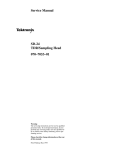
ăStep 1:ă%'- +! & ,++'& 0 &+$0 (,$$"&
'& +! ($*+" #&' ."+! *%$$ &$2&'* ($")*
ăStep 2:ă%'- +! *%$$ '1")"- *).* '& ! *" ' +! *%($"&
! *"& * *!'.& "& " ,) 2
ăStep 3:ă%'- +! *!')+2"),"+ +)%"&+"'& & (+) +!& +! )'&+
(&$ & +! *"& )'% +! "&+)&$ "),"+)0
ăStep 4:ă&*+$$ +! "&+)&$ "),"+)0 "&+' +! )0 *!"(("& *"& ăStep 5:ă($ +! (+) & *!')+2"),"+ +)%"&+"'& '& +! *%2
($"& ! "&(,+
ăStep 6:ă+,)& +! "&+)&$ "),"+)0 +! "),"+ ') & ++!
))") ') *%($"& ! /!& ') )(")
ăStep 7:ă' )($ +! "&+)&$ "),"+)0 '$$'. +! )%'-$ ()',)*
"& )-)* '))
3Ć4
Maintenance
Maintenance
Remove all four
screws on this
side.
Short Circuit
Termination
Short Circuit
Termination
Remove two
screws on this
side.
Figure 3Ć1:ăSampling Head Screw Locations
SDĆ32 Service Manual
3Ć5
Maintenance
Changing the Sampling Head Identification Number
",) *2//2:-1+ 352')(85) %//2:6 ;28 72 ',%1+) 7,) 6%03/-1+ ,)%( -()17-*-'%=
7-21 180&)5 72 *-7 7,) 5)48-5)0)176 2* ;285 %33/-'%7-21
",) *2//2:-1+ )48-30)17 -1 %((-7-21 72 %1 !)5-)6 6'-//26'23) 25
! !)5-)6 20081-'%7-216 !-+1%/ 1%/;<)5 %1( % 6%03/-1+ ,)%( -6
1)')66%5; 72 3)5*250 7,-6 352')(85)
H
25 %1; 27,)5 '203%7-&/) 7,%7 ,%6 ! ! %1( %1 !==
6)5-%/ 3257 '21*-+85)( *25 H
% 6)5-%/ '%&/)
52')(85) 72 ',%1+) 7,) 6%03/-1+ ,)%( -()17-*-'%7-21 180&)5
ăStep 1:ă!)7 7,) -167580)176 $ !$" 72 167%//
21) 2* 7,) 6,257='-5'8-7 .803)56 %'5266 7,) 7:2 3-16 21 7,) "-0)
%6)21752//)5 2%5( ",)6) 6,257 '-5'8-7 .803)56 %5) /2'%7)( 21
6)9)5%/ .803)5 3-16 21 7,) "-0) %6)21752//)5 &2%5( ",-6 &2%5( -6
/2'%7)( 21 7,) &27720 2* 7,) -167580)17 %1( '%1 &) %'')66)( 21') 7,)
&27720 3%1)/ -6 5)029)( )*)5 72 7,) 6)'7-21 -1 7,) *25 ;285 -167580)17 *25 025) -1*250%7-21 21 %'')66-1+ 7,-6
&2%5( !)) -+85) = *25 7,) /2'%7-21 2* .803)5 #
#
#
#
#
#
#
#
#
#
#
#
#
#
#
#
#
#
#
#
#
#
#
#
#
#
#
#
#
#
#
#
#
#
#
#
#
#
#
#
#
#
#
#
#
#
!
#
!
"
!
#
"
#
"
#
#
"
#
#
#
#
#
"
"
"
"
"
"
"
#
#
#
#
#
#
#
#
#
#
#
#
#
#
#
#
#
#
" #
#
#
#
!
#
#
"
#
#
#
#
#
#
#
#
#
"
#
"
#
#
#
#
J860
#
#
#
"
#
#
"
#
"
"
"
"
#
#
#
"
"
"
"
!
!
"
! #
#
#
"
#
"
#
"
#
"
#
#
"
#
"
"
#
#
#
" "
#
#
#
#
#
#
#
#
#
#
#
#
#
#
#
!
#
#
#
#
#
"
#
#
#
#
#
#
!
#
#
#
"
Figure 3Ć2:ăA5 Time Base/Controller Board Jumper Location
3Ć6
Maintenance
Maintenance
ăStep 2:ă,,0 1- 0&# 3'0& MS DOS ,-#.0'+%
ăStep 3:ă,++#!0 0&# /#.') ! )# 0, 0&# '+/0.1*#+0/ 6
6 -,.0
),!0#" 0 0&# .#. ,$ 0&# '+/0.1*#+0 ,++#!0 0&# ,0&#. #+" ,$ 0&# ! )#
0, 0&# -,.0 ,+ 0&# ăStep 4:ă+/0)) 0&# /*-)'+% &#" '+ +4 /*-)'+% &#" !,*-.0*#+0 '+
0&# '+/0.1*#+0
ăStep 5:ă#0 0&# 0, +" 0&# /3'0!& 0, ăStep 6:ă$0#. 0&# "'%+,/0'!/ .# !,*-)#0# -.#// 0&# 100,+
+" 0&#+ 0,1!& RSĆ232 Parameters
ăStep 7:ă#0 0&# Baud Rate 0, 4800 Bd 0&# Parity 0, none +" 0&#
Stop Bits 0, 1 '+ 0&# RSĆ232 Parameters -,-61- *#+1
ăStep 8:ă+/#.0 0&# *-)'+% #" 0')'04 ,$03.# $),--4 "'/( -.,2'"#"
'+ 0&'/ *+1) '+0, 0&# 5 ".'2# ,$ 0&# /4/0#* !,+0.,))#.
ăStep 9:ă+ 0&# 04-# a: +" 0&#+ -.#// 0&# .#01.+ ,. #+0#. (#4
ăStep 10:ă4-# id +" 0&#+ -.#// 0&# .#01.+ ,. #+0#. (#4
&# 0&#+ "'/-)4/ 0&# $,)),3'+% *#//%#
Make sure 11800 RS232 port is set up as follows:
Baud Rate
Parity
Stop bits
4800
none
1
Enter mainframe head number [1..4]
NOTE
When entering the sampling head number, the 11802 Oscilloscope
and CSA 803 Series Communications Signal Analyzers have only
head number 1 and head number 2. The 11801 Series OscilloĆ
scopes have head number 1 through head number 4. The head
numbers correspond to the sampling head compartments and are
in ascending order (reading from left to right).
SDĆ32 Service Manual
3Ć7
Maintenance
ăStep 11:ă! %# % $" &# %)" % !##% $*
" &# % "#$$ % #%&# !# %# )
% $")$ % !!( $$
Current ID number is: XXXXXXXX"
Enter new ID number (8 characters max):
NOTE
The X's between the quotes represent the current ID number. Eight
is the maximum number of digits allowed and one is the minimum.
Any character is allowed, except a space ( ) character.
ăStep 12:ă
%# ! %! % #%#$ !# % ( %%!
&#
$%#& % ( % $ % $$
Change in channel M configuration
!&# %$ % % %!" ! % $# ăStep 13:ă% % $(% %! % $(% %
%! ăStep 14:ă! '#) % ( %%!
&%%! % %!& Identify
&# "#$$ % ( %%! &# !( ""#$ & # Mainframe
Sampling Heads % System Identification "!"*&" &
3Ć8
Maintenance
Theory of Operation
# 5
$. .$)"' #)) ' #$"#5+ -!*-() .(+'$)" # /#/ ) $)./'' $) /# -$ . $"$/' (+'$)" .$''*.*+ . /# 5
0'/$5#)) ' )$/ ) /# -$ . *((0)$/$*). $")'
)'34 -.
System Functional
Overview
#$. . /$*) .-$ . ) $''0./-/ . /# (%*- !0)/$*). *! /# 5
(+'$)" . $"0- 5
,0$.$/$*)
3./ (
W
/-*
) -/*-
/-* -$1
/-* ).
(+' $")' 0/+0/
Figure 4Ć1:ăSDĆ32 Sampling Head Block Diagram
# .(+'$)" # ,0$.$/$*) .3./ ( + -!*-(. /# !0)/$*) *! 1 -3 !./
.(+' 5)5#*' $-0$/ !*- /# ($)!-( $)./-0( )/ / 0. . '*' )'*"
! & /* #$ 1 #$"# 0-3 ) #$"# /#-*0"#+0/ !*- - + /$/$1 $)+0/
.$")'. *- -)*( $)+0/ .$")'. '$& /#*. !*0) $) 3 $"-( ( .0- 5
( )/. 0-3 + ). *) /# */ /-).$ )/ - .+*). *! /# .(+'$)"
# */ - .+*). ) .$'3 %0./ /#-*0"# /# )#) 0-3
( )0 $) /# ($)!-( # ./-* -$1 .$")' !-*( /# $)./-0( )/ *)/-*'. /# /$($)" *! /# ./-*
.. -/$*) /* /# ,0$.$/$*) .3./ (
# ./-* . ). .$")' $. +-/ *! /# ./-* .$")' - /0-) /* /# $)./-05
( )/ # $)./-0( )/ (*)$/*-. /# /$( 0-/$*) *! /# ./-* -$1 ./-*
. ). '**+ ) %0./. '3 $).$ /# $)./-0( )/ /* ($)/$) *-- /
./-* /$($)"
# !*''*2$)" /2* .05. /$*). .-$ #*2 /# /2* .(+'$)" # +-(5
/ - %0./( )/. **+ $) ) !!. / 0'' !! / .(+'$)" # + -!*-() SDĆ32 Service Manual
4Ć1
Theory of Operation
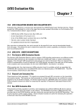
Loop Gain
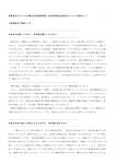
! ! !% ! "!% $ "! #! !! " !$ !$ ! "% $! $ ! "!"! $ ! "! ! ! ! ! ! "!% ! #" ! ! " ! "! #! "!% ! ! #! ! ! ! ! " &
" ! ! $ ! ! #" ! ! "
! "! #! $ !$ ! #" ! ! ! $ #!
" ! ! ! ! #" ! ! "
! ! "! #! $ ! ! ! $ #! #
" & $ ! % ! "! ! ! ! Unity Loop Gain
Insufficient Loop Gain
Excessive Loop Gain
Figure 4Ć2:ăDisplayed Traces at Various Loop Gain Settings
4Ć2
Theory of Operation
Theory of Operation
Offset Null
! "
"
SDĆ32 Service Manual
4Ć3
4Ć4
Replaceable Parts
!"* *+"'& '&+"&* $"*+ ' +! '%('&&+* +!+ ) )($$ ') +!
1 %($"& * *)" $'. ,* +!"* $"*+ +' "&+"0 & '))
)($%&+ ()+*
Parts Ordering
Information
($%&+ ()+* ) -"$$ )'% ') +!)', ! 0',) $'$ #+)'&"/ &
*)-" &+) ') )()*&++"-
!& * +' #+)'&"/ "&*+),%&+* ) *'%+"%* % +' '%%'+
"%()'- '%('&&+* * +!0 '% -"$$ & +' "- 0', +! &"+
' +! $+*+ "),"+ "%()'-%&+* !)') .!& '))"& ()+* "+ "*
"%(')+&+ +' "&$, +! '$$'."& "&')%+"'& "& 0',) '))
H
)+ &,%)
H
&*+),%&+ +0( ') %'$ &,%)
H
&*+),%&+ *)"$ &,%)
H
&*+),%&+ %'""+"'& &,%) " (($"$
()+ 0', ')) !* & )($ ."+! ")&+ ') "%()'- ()+ 0',)
$'$ #+)'&"/ *)-" &+) ') )()*&++"- ."$$ '&++ 0', '&)&"&
&0 !& "& +! ()+ &,%)
!& "&')%+"'& " &0 "* $'+ + +! )) ' +!"* %&,$
Module Replacement
! 1 %($"& "* *)-" 0 %',$ )($%&+ *' +!) )
+!) '(+"'&* 0', *!',$ '&*")
SDĆ32 Service Manual
H
Module Exchange. & *'% ** 0', %0 /!& 0',) %',$ ')
)%&,+,) %',$ !* %',$* '*+ *" &""&+$0 $** +!&
&. %',$* & %+ +! *% +')0 *(""+"'&* ') %') "&')1
%+"'& ',+ +! %',$ /!& ()' )% $$ /+ H
Module Repair. ', %0 *!"( 0',) %',$ +' ,* ') )(") +) .!"!
. ."$$ )+,)& "+ +' 0',
H
New Modules. ', %0 (,)!* &. )($%&+ %',$* "& +!
*% .0 * '+!) )($%&+ ()+*
5Ć1
Replaceable Parts
Using the
Replaceable
Parts List
)*!' #$'")$# # ) %!! ')( () ( ''# $' &*
')'+! #'()## ) ()'*)*' # )*'( $ ) !() ,!! !% -$*
# ) !! ) #$'")$# -$* # $' $''# '%!"#) %')(
Item Names
# ) %!! ')( () # )" " ( (%') '$" ) ('%.
)$# - $!$# *( $ (% !"))$#( # )" " "- ($".
)"( %%' ( #$"%!) $' *')' )" " #))$# '! )!$# #$$ . # *( ,' %$((!
Abbreviations
'+)$#( $#$'" )$ "'# )$#! )#'( #())*) ()#' 5Ć2
Replaceable Parts
Replaceable Parts
CROSS INDEX - MFR. CODE NUMBER TO MANUFACTURER
Mfr.
Code
Manufacturer
Address
City, State, Zip Code
! ! # ! ! # $ ! ! " ! " SDĆ32 Service Manual
5Ć3
Replaceable Parts
Fig. &
Index
No.
Tektronix
Part No.
Serial No.
Effective Dscont
Qty
12345 Name & Description
Mfr.
Code
Mfr. Part No.
!! ) ! ) %
!## * $
## % $
#! % " " #! %
%% "#%$
%
!## * $
$#( ) $%
%% "#%$
%
!## * $
$$" %
!## * $
!&# $$*$
#" & % STANDARD ACCESSORIES
"%#!)
'
%#!)$!#% #&%$
+'
$
&%&$#$
&%$#'$
OPTIONAL ACCESSORIES
5Ć4
)%&#$" & %
$% #
)%&#$" & %
&#!" )%&#$" & %
& % !
)%&#$" & %
&$%# )%&#$" & %
$(%+# )%&#$" & %
" $
Replaceable Parts
Replaceable Parts
Figure 5Ć1:ăExploded View of the SDĆ32 Sampling Head
SDĆ32 Service Manual
5Ć5
5Ć6