1
DCS-3950 series Ethernet Switch
Manual
Version 1.4
Digitalchina Networks Co.,Ltd All Rights Reserved 2008_06
http://networks.digitalchina.com
DCS-3950 series Ethernet switch manual
Preface DCS-3950 series is a high performance ethernet switch which support wire-speed
Layer 2 switching.
DCS-3950 series can seamlessly support various network interfaces from 10Mb,
100Mb, 1000Mb
DCS-3950
Ethernets.
series is an excellent choice as access layer switch for education,
government and large/medium enterprise networks..DCS-3950
DCS-3950-26C,
DCS-3950-28CT,
DCS-3950-52C. , DCS-3950
DCS-3950-28C
and
series comprises
DCS-3950-52CT,
series provide 24 10/100 ports+2 Gigabit Ethernet
fiber/copper ports; 24 10/100 ports+2 Gigabit Ethernet fiber/copper ports +2 Gigabit
copper ports ;24 10/100 ports+4 Gigabit Ethernet fiber/copper ports;48 10/100 ports+2
Gigabit Ethernet fiber/copper ports +2 Gigabit copper ports;48 10/100 ports+4 Gigabit
Ethernet fiber/copper ports.
We are providing this manual for your better understanding, using and maintenance
of the DCS-3950 series. We strongly recommend you to read through this manual
carefully before installation and configuration to avoid possible damage to the switch and
malfunction.
Software or hardware of the product may be updated after the release
of this manual. And if this manual should be updated according to the
product update, it is not promised the customers would be informed about
the update. To get more information about the product, or to get software
updates or manual updates, please go to http://networks.digitalchina.com
or dial 800-810-9119(in China) to get support.
II
DCS-3950 series Ethernet switch manual
Contents Preface_______________________________________________________________ II Contents____ _________________________________________________________III Chapter 1 Introduction of Products _______________________________________ 1 1.1 Brief Introduction _____________________________________________________ 1 1.1.1 Overview _______________________________________________________________ 3 1.1.2 Features and Benefits _____________________________________________________ 3 1.1.3 Main Features ___________________________________________________________ 5 1.2 Technical specifications ________________________________________________ 6 1.3 Physical Specifications _________________________________________________ 7 1.4 Product appearance ___________________________________________________ 7 1.4.1 Product Front Panel View _________________________________________________ 7 1.4.2 Product back panel view __________________________________________________ 8 1.4.3 Status LEDs_____________________________________________________________ 8 Chapter 2 Hardware Installation _________________________________________ 10 2.1 Installation Notice ____________________________________________________ 10 2.1.1 Environmental Requirements _____________________________________________ 10 2.1.2 Installation Notice ______________________________________________________ 13 2.1.3 Security Warnings ______________________________________________________ 13 2.2 Installation Preparation _______________________________________________ 14 2.2.1 Verify the Packet Contents _______________________________________________ 14 2.2.2 Required Tools and Utilities ______________________________________________ 14 2.3 Hardware Installation ________________________________________________ 14 2.3.1 Installing the Switch _____________________________________________________ 14 2.3.2 Connecting Console _____________________________________________________ 15 2.3.3 Power Supply Connection ________________________________________________ 16 Chapter 3 Setup Configuration __________________________________________ 18 3.1 Setup Configuration __________________________________________________ 18 3.2 Main Setup Menu ____________________________________________________ 18 3.3 Setup Submenu ______________________________________________________ 18 3.3.1 Configuring switch hostname _____________________________________________ 18 3.3.2 Configuring Vlan1 Interface ______________________________________________ 19 3.3.3 Telnet Server Configuration ______________________________________________ 19 3.3.4 Configuring Web Server _________________________________________________ 20 III
DCS-3950 series Ethernet switch manual
3.3.5 Configuring SNMP______________________________________________________ 21 3.3.6 Exiting Setup Configuration Mode _________________________________________ 22 Chapter 4 Switch Management __________________________________________ 23 4.1 Management Options _________________________________________________ 23 4.1.1 Out-of-band Management ________________________________________________ 23 4.1.2 In-band Management ____________________________________________________ 26 4.2 Management Interface ________________________________________________ 30 4.2.1 CLI Interface __________________________________________________________ 30 4.2.2 Web Interface __________________________________________________________ 37 Chapter 5 Basic Switch Configuration ____________________________________ 39 5.1 Basic Switch Configuration Command List _______________________________ 39 5.1.1 clock set _______________________________________________________________ 39 5.1.2 config _________________________________________________________________ 39 5.1.3 exec timeout ___________________________________________________________ 40 5.1.4 exit_ __________________________________________________________________ 40 5.1.5 help_ _________________________________________________________________ 40 5.1.6 ip host ________________________________________________________________ 41 5.1.7 ip http server___________________________________________________________ 41 5.1.8 hostname ______________________________________________________________ 41 5.1.9 reload _________________________________________________________________ 42 5.1.10 set default ____________________________________________________________ 42 5.1.11 setup _________________________________________________________________ 42 5.1.12 language _____________________________________________________________ 42 5.1.13 web-user _____________________________________________________________ 43 5.1.14 write _________________________________________________________________ 43 5.1.15 show cpu usage ________________________________________________________ 43 5.1.16 show tech-support _____________________________________________________ 44 5.1.17 vendorcontact _________________________________________________________ 44 5.1.18 vendorlocation ________________________________________________________ 44 5.1.19 web-language _________________________________________________________ 44 5.2 Monitor and Debug Command List _____________________________________ 45 5.2.1 Ping____________________________________________________________________45 5.2.2 Telnet _________________________________________________________________ 46 5.2.3 SSH ____________________________________________________________________50 5.2.4 Traceroute _____________________________________________________________ 54 5.2.5 Show _________________________________________________________________ 55 5.2.6 Debug_________________________________________________________________ 61 5.3 Configure the IP Address of the Switch __________________________________ 61 5.3.1 Switch IP Addresses Configuration Task List ________________________________ 61 5.3.2 Switch IP Address Configuration Command List _____________________________ 62 5.4 SNMP Configuration _________________________________________________ 63 IV
DCS-3950 series Ethernet switch manual
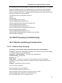
5.4.1 Introduction to SNMP ___________________________________________________ 63 5.4.2 Introduction to MIB _____________________________________________________ 65 5.4.3 Introduction to RMON __________________________________________________ 66 5.4.4 SNMP Configuration ____________________________________________________ 66 5.4.5 Typical SNMP Configuration Example _____________________________________ 73 5.4.6 SNMP Troubleshooting __________________________________________________ 73 5.5 Switch Upgrade ______________________________________________________ 78 5.5.1 BootROM Upgrade _____________________________________________________ 78 5.5.2 FTP/TFTP Upgrade _____________________________________________________ 80 5.6 System Log _________________________________________________________ 93 5.6.1 Introduction to the System Log ____________________________________________ 93 5.6.2 System Log Configuration ________________________________________________ 95 5.6.3 System Log Configuration Example _______________________________________ 100 5.6.4 System Log troubleshooting _____________________________________________ 100 5.7 Classified Configuration _____________________________________________ 102 5.7.1 Introduction of Classified Configuration ___________________________________ 102 5.7.2 Configure the Classified Configuration ____________________________________ 102 5.8 Port Isolation _______________________________________________________ 104 5.8.1 Introduction of Port Isolation ____________________________________________ 104 5.8.2 Port Isolation Configuration _____________________________________________ 104 Chapter 6 Cluster Configuration ________________________________________ 106 6.1 Introduction to Cluster Network Management ___________________________ 106 6.2 Cluster Network Management Configuration ____________________________ 106 6.2.1 Cluster Network Management Configuration Task List_______________________ 106 6.2.2 Clustering Configuration Command List __________________________________ 108 6.3 Cluster configuration Example ________________________________________ 114 6.4 Cluster Administration Troubleshooting ________________________________ 115 6.4.1 Monitor and Debug Command List ________________________________________115 6.4.2 Cluster administration troubleshooting _____________________________________118 Chapter 7 Port Configuration __________________________________________ 119 7.1 Port Introduction ___________________________________________________ 119 7.2 Port Configuration __________________________________________________ 119 7.2.1 Network Port Configuration ______________________________________________119 7.2.2 VLAN Interface Configuration ___________________________________________ 127 7.2.3 Port Mirroring Configuration ____________________________________________ 128 7.3 Port Configuration Example __________________________________________ 132 7.4 Port Troubleshooting ________________________________________________ 133 7.4.1 Monitor and Debug Command List _______________________________________ 133 Chapter 8 MAC Table Configuration _____________________________________ 137 V
DCS-3950 series Ethernet switch manual
8.1 Introduction to MAC Table ___________________________________________ 137 8.1.1 Obtaining MAC Table __________________________________________________ 137 8.1.2 Forward or Filter ______________________________________________________ 138 8.2 MAC address table configuration Command List _________________________ 139 8.2.1 mac-address-table aging-time ____________________________________________ 139 8.2.2 mac-address-table______________________________________________________ 140 8.2.3 mac-address-table blackhole _____________________________________________ 141 8.2.4 clear mac-address-table dynamic _________________________________________ 141 8.3 Typical Configuration Example________________________________________ 141 8.4 Troubleshooting ____________________________________________________ 142 8.4.1 Monitor and Debug Command List _______________________________________ 142 8.4.2 Troubleshooting _______________________________________________________ 143 8.5 MAC Address Function Extension _____________________________________ 143 8.5.1 MAC Address Binding __________________________________________________ 143 Chapter 9 VLAN Configuration _________________________________________ 151 9.1 Introduction to VLAN _______________________________________________ 151 9.2 VLAN Configuration ________________________________________________ 152 9.2.1 VLAN Configuration Task List ___________________________________________ 152 9.2.2 VLAN Configuration Command List ______________________________________ 154 9.2.3 Typical VLAN Application ______________________________________________ 158 9.3 Dot1q-tunnel Configuration __________________________________________ 160 9.3.1 Dot1q-tunnel Introduction_______________________________________________ 160 9.3.2 Dot1q-Tunnel Configuration Task List_____________________________________ 161 9.3.3 Dot1q-tunnel Command List_____________________________________________ 162 9.3.4 Typical Applications of the Dot1q-tunnel ___________________________________ 164 9.3.5 Dot1q-tunnel Troubleshooting____________________________________________ 165 9.4 Protocol VLAN Configuration_________________________________________ 165 9.4.1 Protocol VLAN Introduction _____________________________________________ 165 9.4.2 Protocol VLAN Configuration Task List ___________________________________ 166 9.4.3 Protocol VLAN Command List ___________________________________________ 166 9.4.4 Protocol VLAN Troubleshooting__________________________________________ 168 9.5 VLAN Troubleshooting ______________________________________________ 168 9.5.1 Monitor and Debug Command List _______________________________________ 168 Chapter 10 MSTP Configuration ________________________________________ 170 10.1 Introduction to MSTP ______________________________________________ 170 10.1.1 MSTP Region ________________________________________________________ 170 10.1.2 Port Roles ___________________________________________________________ 171 10.1.3 MSTP Load Balance___________________________________________________ 172 10.2 MSTP Configuration _______________________________________________ 172 VI
DCS-3950 series Ethernet switch manual
10.2.1 MSTP Configuration Task List __________________________________________ 172 10.2.2 MSTP Command List _________________________________________________ 175 10.3 MSTP Configuration Example _______________________________________ 185 10.4 MSTP Troubleshooting______________________________________________ 190 10.4.1 Monitor and Debug Command List ______________________________________ 190 10.4.2 MSTP Troubleshooting ________________________________________________ 194 Chapter 11 IGMP Snooping ____________________________________________ 195 11.1 Introduction to IGMP Snooping ______________________________________ 195 11.2 IGMP Snooping Configuration _______________________________________ 195 11.2.1 IGMP Snooping Configuration Task List __________________________________ 195 11.2.2 IGMP Snooping configuration Command List _____________________________ 197 11.3 IGMP Snooping Example ____________________________________________ 201 11.4 IGMP Snooping Troubleshooting _____________________________________ 204 11.4.1 IGMP Snooping Monitor and Debug Command List ________________________ 204 11.4.2 IGMP Snooping Troubleshooting ________________________________________ 206 Chapter 12 Multicast VLAN Configuration ________________________________ 207 12.1 Multicast VLAN Introduction ________________________________________ 207 12.2 Multicast VLAN Configuration_______________________________________ 207 12.2.1 Multicast VLAN Configuration Task List _________________________________ 207 12.2.2 Multicast VLAN Configuration Command List ____________________________ 208 12.3 Multicast VLAN Example ___________________________________________ 209 Chapter 13 DCSCM Configuraion _______________________________________ 211 13.1 DCSCM Introduction _______________________________________________ 211 13.2 DCSCM Configuration _____________________________________________ 211 13.2.1 DCSCM Configuration Task List _________________________________________211 13.2.2 DCSCM Command List________________________________________________ 214 13.3 DCSCM Typical Example ___________________________________________ 219 13.4 DCSCM Troubleshooting ____________________________________________ 220 13.4.1 DCSCM Debug and Monitor Command List ______________________________ 220 13.4.2 DCSCM Troubleshooting ______________________________________________ 222 Chapter 14 802.1x Configuration _______________________________________ 223 14.1 Introduction to 802.1x ______________________________________________ 223 14.2 802.1x Configuration _______________________________________________ 224 14.2.1 802.1x Configuration Task List __________________________________________ 224 14.2.2 802.1x Configuration Command List _____________________________________ 228 14.3 802.1x Application Example _________________________________________ 240 VII
DCS-3950 series Ethernet switch manual
14.4 802.1x Troubleshooting______________________________________________ 241 14.4.1 802.1x Monitor and debug Command List ________________________________ 241 14.4.2 802.1x Troubleshooting ________________________________________________ 248 Chapter 15 ACL Configuration _________________________________________ 249 15.1 Introduction to ACL ________________________________________________ 249 15.2 Access-list _________________________________________________________ 249 15.2.1 Access-group _________________________________________________________ 249 15.2.2 Access-list Action and Global Default Action _______________________________ 249 15.3 ACL Configuration _________________________________________________ 250 15.3.1 ACL Configuration Task List ___________________________________________ 250 15.3.2 ACLCommand List ___________________________________________________ 264 15.4 ACL Example _____________________________________________________ 277 15.5 ACL Troubleshooting _______________________________________________ 279 15.5.1 Monitor and Debug Command List ______________________________________ 279 15.5.2 ACL Troubleshooting __________________________________________________ 282 Chapter 16 AM Configuration __________________________________________ 283 16.1 AM Introduction ___________________________________________________ 283 16.2 AM pool __________________________________________________________ 283 16.3 AM Configuration _________________________________________________ 283 16.3.1 AM Configuration Task List ____________________________________________ 283 16.3.2 AM Command List ____________________________________________________ 284 16.4 AM Example ______________________________________________________ 286 16.5 AM Troubleshooting ________________________________________________ 287 16.5.1 AM Debug and Monitor Command List __________________________________ 287 16.5.2 AM Troubleshooting___________________________________________________ 288 Chapter 17 Port Channel Configuration __________________________________ 289 17.1 Introduction to Port Channel ________________________________________ 289 17.2 Port Channel Configuration _________________________________________ 290 17.2.1 Port Channel Configuration Task List ____________________________________ 290 17.2.2 Port ChannelConfiguration Command List _______________________________ 291 17.3 Port Channel Example ______________________________________________ 292 17.4 Port Channel Troubleshooting________________________________________ 295 17.4.1 Debug and Monitor Command List ______________________________________ 295 17.4.2 Port Channel Channel Troubleshooting ___________________________________ 299 Chapter 18 DHCP Configuration ________________________________________ 301 18.1 Introduction to DHCP ______________________________________________ 301 18.2 DHCP Server Configuration _________________________________________ 302 VIII
DCS-3950 series Ethernet switch manual
18.2.1 DHCP Sever Configuration Task List_____________________________________ 302 18.2.2 DHCP Server Configuration Command List _______________________________ 304 18.2.3 DHCP Server Configuration Example ____________________________________ 312 18.3 DHCP Troubleshooting _____________________________________________ 313 18.3.1 Monitor and Debug Command List ______________________________________ 313 18.3.2 DHCP Troubleshooting ________________________________________________ 317 Chapter 19 DHCP Snooping Configuration _______________________________ 318 19.1 DHCP Snooping Introduction ________________________________________ 318 19.2 DHCP Snooping Configuration _______________________________________ 318 19.2.1 DHCP Snooping Configuration Task List _________________________________ 318 19.2.2 DHCP Snooping Command List _________________________________________ 321 19.2.3 DHCP Snooping Typical Applications ____________________________________ 326 19.3 DHCP Snooping Troubleshooting _____________________________________ 327 19.3.1 Monitor and Debug Command List ______________________________________ 327 19.3.2 DHCP SnoopingTroubleshooting ________________________________________ 330 Chapter 20 ARP Guard Configuration ___________________________________ 332 20.1 ARP Guard introduction ____________________________________________ 332 20.2 ARP Guard Configuration ___________________________________________ 333 20.2.1 ARP GuardConfiguration Task List______________________________________ 333 20.2.2 ARP Guard Command List _____________________________________________ 333 Chapter 21 ARP Scanning Prevention ___________________________________ 334 21.1 Introduction_______________________________________________________ 334 21.2 Scanning Prevention Configuration ___________________________________ 334 21.2.1 Scanning Prevention Configuration Task List ______________________________ 334 21.2.2 ARP Scanning Prevention Command List _________________________________ 336 21.3 ARP Scanning Prevention Troubleshooting _____________________________ 339 21.3.1 ARP Scanning Prevention Debug Command List ___________________________ 339 21.4 ARP Scanning Prevention Typical Example _____________________________ 341 Chapter 22 Port Loopback Detection ____________________________________ 343 22.1 Introduction to Port Loopback Detection ______________________________ 343 22.2 Port Loopback Detection Configuration _______________________________ 343 22.2.1 Port Loopback Detection Configuration Task List __________________________ 343 22.2.2 Port Loopback Detection Command List__________________________________ 344 22.3 Port Loopback Detection Example ____________________________________ 346 22.4 Port Loopback Detection Troubleshooting ______________________________ 347 22.4.1 Port Loopback Debugging Command List ________________________________ 347 22.4.2 Port Loopback Dection Troubleshooting __________________________________ 348 IX
DCS-3950 series Ethernet switch manual
Chapter 23 SNTP Configuration ________________________________________ 349 23.1 SNTP Introduction _________________________________________________ 349 23.2 SNTP Configuration ________________________________________________ 350 23.2.1 SNTP Configuration Task List __________________________________________ 350 23.2.2 SNTP Command List __________________________________________________ 350 23.3 SNTP Troubleshooting ______________________________________________ 351 23.3.1 SNTP Debugging Command List ________________________________________ 351 23.4 Typical SNTP Configuration Example _________________________________ 353 Chapter 24 QoS Configuration _________________________________________ 354 24.1 Introduction to QoS ________________________________________________ 354 24.1.1 QoS Terms ___________________________________________________________ 354 24.1.2 QoS Implementation __________________________________________________ 355 24.1.3 Basic QoS Model______________________________________________________ 355 24.2 QoS Configuration _________________________________________________ 359 24.2.1 QoS Configuration Task List ____________________________________________ 359 24.2.2 QoS Command List ___________________________________________________ 362 24.3 QoS Example ______________________________________________________ 370 24.4 QoS Troubleshooting _______________________________________________ 373 24.4.1 QoS Monitor and Debug Command List __________________________________ 373 24.4.2 QoS Troubleshooting __________________________________________________ 375 Chapter 25 Layer 3 Configuration _______________________________________ 377 25.1 Layer 3 Interface___________________________________________________ 377 25.1.1 Introduction to Layer 3 Interface ________________________________________ 377 25.1.2 Layer3 interface configuration __________________________________________ 377 25.2 ARP _____________________________________________________________ 382 25.2.1 Introduction to ARP ___________________________________________________ 382 25.2.2 ARP Configuration ____________________________________________________ 382 25.2.3 ARP Forwarding Troubleshooting _______________________________________ 383 X
DCS-3950 series Ethernet switch manual
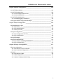
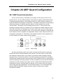
Chapter 1 Introduction of Products
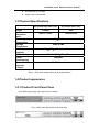
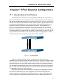
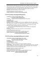
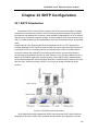
1.1 Brief Introduction
Fig 1-1
DCS-3950-26C switch
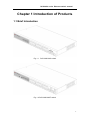
Fig 1-2 DCS-3950-28CT switch
1
DCS-3950 series Ethernet switch manual
Fig 1-3 DCS-3950-28C switch
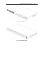
Fig 1-4 DCS-3950-52CT switch
2
DCS-3950 series Ethernet switch manual
Fig 1-5 DCS-3950-52C switch
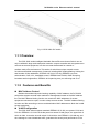
1.1.1 Overview
The DCS-3950 series Intelligent Stackable Secure Ethernet Access Switch can not
only be utilized in large-scale enterprise networks,campus networks and metropolitan area
networks as access equipment, but also can meet the demand for network of
medium-scale office environment. This series of switch has unique network access
functions and flexible management of network, including MAC binding/filtering, limiting the
total number of Mac addresses, IEEE802.1Q VLAN, PVLAN, IEEE802.1x access
authentication, QoS, ACL, bandwidth control, IEEE802.3ad TRUNK, IGMP Snooping,
broadcast storm suppression, IEEE802.1d/w spanning tree, port mirroring and so on.
1.1.2 Features and Benefits
MAC Address Control
Besides the standard dynamic learning capability of MAC address, the DCS-3950
series also supports several other methods of management based on the MAC address
list. The MAC address binding function can restrict the MAC addresses of access
equipment connected to a port, in order to keep access secure. The MAC address filtering
function can filter according to source and destination MAC addresses to block the invalid
access equipment.
VLAN Configuration
The DCS-3950 series supports standard IEEE802.1Q VLAN, port-protect VLAN and
PVLAN. IEEE802.1 Q VLAN can divide ports into several VLAN groups, the upper limit of
which is 4094. It can also do multi-switch VLAN division via IEEE802.1 Q VLAN tag, and
thus manage to control broadcast traffic, guarantee the security and performance of the
3
DCS-3950 series Ethernet switch manual
network at the same time. PVLAN function can divide ports into isolated ports and
community ports, in order to isolate or connect ports as demanded by network
applications.
QoS
DCS-3950 series fully support QoS policy. Users can specify 4 priority queues on
each port. WRR/SP/SWRR scheduling is also supported. DCS-3950 series also supports
the port security. The traffic can be sorted by port, VLAN, DSCP, IP precedence and ACL
table. User can also modify packets’ DSCP and IP precedence values. Users can specify
different bandwidths for voice/data/video to customize different qualities of service.
ACL
DCS-3950 series supports complete ACL policy. ACL is a mechanism realized by
switches to filter IP data. By allowing or denying specific data packets entering/leaving the
network, a switch can control the network access and effectively guarantee the secure
operation of network.
DCS-3950 series supports IP -based, MAC-based and
MAC-IP-based ingress filtering, it can also filter data based on the information of
source/destination IP address, source/destination MAC address, IP protocol type,
TCP/UDP port, IP precedence, time range and ToS, etc..
IEEE802.1x Access Authentication
The DCS-3950 series not only supports port-based IEEE802.1x authentication mode,
but also supports MAC -based authentication mode. It can set the upper limit of access
authentication users per port, realize dynamic secure authentication mode basing on MAC
address, and bind the MAC address of authenticated equipment to a port. Combining
these IEEE802.1x authentication modes with the authentication and cost-counting
products of the Digital China Networks Limited, we can supply a whole set of integrated
IEEE802.1x access authentication and cost-counting resolution to satisfy the need of
access, authentication and cost-counting, ensuring the network’s security and its ability to
operate.
Bandwidth Control (Speed Limit of Port)
The DCS-3950 series can control the upstream/ downstream bandwidth and provide
different access bandwidth for users of different levels. Each port can set its bandwidth
rate as demanded to meet the need of access network to control access bandwidth.
TRUNK
The DCS-3950 series supports IEEE802.3ad standard TRUNK. It can also realize link
redundancy and traffic load balance.
IGMP Snooping
The DCS-3950 series supports multicast applications which are based on IGMP
Snooping mechanism, and as a result, it can realize all kinds of multicast services,
diminish the network traffic and meet the requirement of multicast services like multimedia
playing, remote teaching and entertainment.
Broadcast Storm Suppression
The DCS-3950 series supports broadcast storm suppression, can effectively control
broadcast storm, decrease useless occupancy of bandwidth, and increase the overall
performance of network.
4
DCS-3950 series Ethernet switch manual
Spanning tree
The DCS-3950 series supports IEEE802.1D spanning tree and IEEE802.1w rapid
spanning tree. Spanning tree can effectively avoid loop, and at the same time, create a
redundant backup for the link.
Port Mirroring
The DCS-3950 series supports port mirroring, which can mirror the inbound/outbound
traffic of one or more ports to another port, in order to detect relative information of data.
This function can be used to debug network faults and monitor the network traffic.
DHCP Server, Client
The DCS-3950 series supports DHCP server, which can dynamically allocate IP
addresses for equipments, and bind MAC with IP by designating a specified IP for a
specified MAC.
RADIUS
The DCS-3950 series supports RADIUS (Remote Authentication Dial In User
Service). RADIUS allows users to authenticate identity via IEEE802.1x protocol.
Complete Network Management
The DCS-3950 series can do out-of-band and in-band management via Console,
Telnet, Web and SNMP. Console and Telnet management support standard
CLI( Command Line Interface), which makes the operation easier and faster, and also
provide bilingual instructions in Chinese and English. Web management provides a
remote browsing graphic management interface to make management more direct and
convenient, to enable fast check of working state and to do real-time configuration
management. SNMP management is in accordance with V1, V2C and V3 standard
version, supporting Ether-Like MIB, Bridge MIB and MIB II, as well as standard
management information libraries such as RMON 1/2/3/9 MIB II etc. The full SNMP
network management can be realized via LinkManager, one China network managing
software developed by the Digital China Limited. The DCS-3950 series also supports SSH
protocol to farthest ensure the safety of configuration management. What’s more, the
DCS-3950 series provide an unique function to manage and set the IP of workstations,
enabling the switch to automatically filter invalid remote network management access and
guaranteeing the efficiency, security and coherence of remote network management
access.
1.1.3 Main Features
Applying Store-and-Forward switch mode to ensure block-free transmission.
All of the RJ-45 ports support MDI/MDI-X self-adaptation can be conveniently
cascade connected to other switch using straight-through twisted pair.
Providing Console port.
Allowing users to check the working state and statistic information of ports.
Can be rebooted locally and remotely as well as reset the switch to the default
configuration.
Can update the firmware using TFTP/FTP.
5
DCS-3950 series Ethernet switch manual
Can be fixed in a standard 19-inch frame.
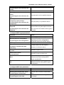
1.2 Technical specifications
Protocols and Standards
Management Standards and Methods
RFC1213 MIB II
RFC1493 Bridge MIB
RFC1643 Ether-Like MIB
Private MIB
Management Protocols and Methods
CLI command line
SNMP V1/V2c/V3 enabled, available through Network management
systems such as LinkManager
Web and Telnet management enable
RFC1757 RMON(1、2、3、9)
MIB
IEEE802.3 10BASE-T Ethernet
IEEE802.3u 100BASE-TX/FX Fast Ethernet
IEEE802.3x Flow control
IEEE802.1x access control
IEEE802.1d/w/s Spanning Tree
IEEE802.1p Class of Service
IEEE802.1q VLAN
IEEE802.3ad Link Aggregation
TFTP/FTP
DHCP
BootP
Telnet
IP/UDP/TCP/ICMP
HTTP
SNMP V1/V2c/V3
CLI command line
SNMP V1/V2C enabled, available through Network management systems
such as LinkManager
Telnet management enabled
RFC1757 RMON(1, 2, 3, 9)
MIB Library
RFC1213 MIB II
RFC1493 Bridge MIB
6
DCS-3950 series Ethernet switch manual
RFC1643 Ether-Like MIB
Digital -China Private MIB
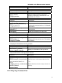
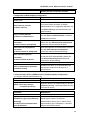
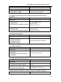
1.3 Physical Specifications
weight
Dimension
(mm)
Operating
Temperature
Storage
Temperature
Relative
humidity
AC Power Input
DCS-3950-26C/28CT/28C
DCS-3950-52CT/52C
2.25KG
3KG
440×171.2×43
440×229×44
0°C~50°C
-40°C~70°C
10%~90%,with no condensate
100~240VAC,50~60Hz
Power
Consumption
Mean
Time
Between
Failures
30W Max
80,000 Hours
Table1-1 DCS-3950 series switch physical specification
1.4 Product appearance
1.4.1 Product Front Panel View
DCS-3950 series switch front panel view as follows:
Fig 1-6 DCS-3950-26C switch front panel view
7
DCS-3950 series Ethernet switch manual
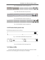
Fig 1-7 DCS-3950-28CT switch front panel view
Fig 1-8 DCS-3950-28C switch front panel view
Fig 1-9 DCS-3950-52CT switch front panel view
Fig 1-10 DCS-3950-52C switch front panel view
1.4.2 Product back panel view
DCS-3950 series back panel view as follows:
Fig 1-11 DCS-3950-26C/28CT/28C back panel view
Fig 1-12 DCS-3950-52CT/52C back panel view
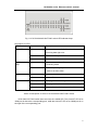
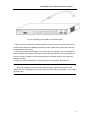
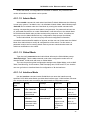
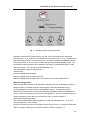
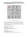
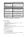
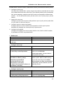
1.4.3 Status LEDs
The LEDs of DCS-3950 series switch include: PWR, DIAG, Link/Act and 1000M.
Please refer to the following graph for meanings of the LED lights:
8
DCS-3950 series Ethernet switch manual
Fig 1-13 DCS-3950-26C/28CT/28C switch LED indicator lamp
Description of LEDs
LED
Sstate
Description
Link/ACT
Blink
The port is successfully linked and is sending
/receiving data right now.
Off
The state of the port is down.
On
Link succeeds
On
The corresponding
connecting mode.
Off
The corresponding G port is in 100M connecting
mode or in down state.
On
Power on
Off
Power off
1000M indicator
lamp
Power
DIAG
Green,blink
G
port
is
in
1000M
The program is initializing.
On
The program has been initialized successfully.
yellow,blink
The initialization of the program has failed.
Table1-2 Description of LEDs in DCS-3950-26C/28CT/28C Switch
DCS-3950-52CT/52C switch does not have the 1000M LED. The Link/ACT LED of its
100M port is above the corresponding port, while the Link/ACT LED of its 1000M port is on
the right of the corresponding port.
9
DCS-3950 series Ethernet switch manual
Chapter 2 Hardware Installation
2.1 Installation Notice
To ensure the proper operation of DCS-3950 series and your physical security, please
read carefully the following installation guide.
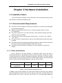
2.1.1 Environmental Requirements
The switch must be installed in a clean area. Otherwise, the switch may be damaged
by electrostatic adherence.
Maintain the temperature within 0 to 50 °C and the humidity within 5% to 95%,
non-condensing.
The switch must be put in a dry and cool place. Leave sufficient spacing around the
switch for good air circulation.
The switch must work in the right range of power input AC power: 100 ~ 240VAC
(50 ~ 60Hz).
The switch must be well grounded in order to avoid ESD damage and physical injury
of people.
The switch should avoid sunlight perpendicular incidence. Keep the switch away from
heat sources and strong electromagnetic interference sources.
The switch must be mounted to a standard 19’’ rack or placed on a clean level
desktop.
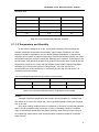
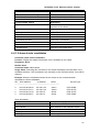
2.1.1.1 Dust and Particles
Dust is harmful to the safe operation of DCS-3950 series. Dust can lead to
electrostatic adherence, especially likely under low relative humidity, causing poor contact
of metal connectors or contacts. Electrostatic adherence will result in not only reduced
product lifespan, but also increased chance of communication failures. The recommended
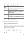
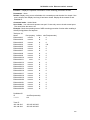
value for dust content and particle diameter in the site is shown below:
Max Diameter (µm)
0.5
1
3
5
Max Density
(particles/m³)
1.4×10⁷
7×10⁵
2.4×10⁵
1.3×10⁵
Table 2-1 Environmental Requirements: Dust
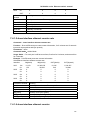
In addition, salt, acid and sulfide in the air are also harmful to the switch. Such harmful
gases will aggravate metal corrosion and the aging of some parts. The site should avoid
harmful gases, such as SO2, H2S, NO2, NH3 and Cl2, etc. The table below details the
10
DCS-3950 series Ethernet switch manual
threshold value.
Gas
Average (mg/m³)
Max (mg/m³)
SO2
0.2
1.5
H2S
0.006
0.03
NO2
0.04
0.15
NH3
0.05
0.15
Cl2
0.01
0.3
Table 2-2 Environmental Requirements: Particles
2.1.1.2 Temperature and Humidity
As the switch is designed to no fan, it’s physical heat-away ,the site should still
maintain a desirable temperature and humidity. High-humidity conditions can cause
electrical resistance degradation or even electric leakage, degradation of mechanical
properties and corrosion of internal components. Extreme low relative humidity may cause
the insulation spacer to contract, making the fastening screw insecure. Furthermore, in dry
environments, static electricity is liable to be produced and cause harm to internal circuits.
Temperature extremes can cause reduced reliability and premature aging of insulation
materials, thus reducing the switch’s working lifespan. In the hot summer, it is
recommended to use air-conditioners to cool down the site. And the cold winter, it is
recommenced to use heaters.
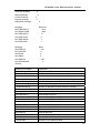
The recommended temperature and humidity is shown below:
Temperature:
Relative humidity
Long term condition
Short term condition
Long term condition
Short term condition
15 ~ 30°C
0 ~ 50°C
40 ~ 65%
10 ~ 95%
Table 2-3 Environmental Requirements: Temperature and Humidity
Caution!
A sample of ambient temperature and humidity should be taken at 1.5m above the
floor and 0.4m in front of the switch rack, with no protective panel covering the front and
rear of the rack.
Short term working conditions refer to a maximum of 48 hours of continued operation
and an annual cumulative total of less than 15 days. Formidable operation conditions
refers to the ambient temperature and relative humidity value that may occur during an
air-conditioning system failure, and normal operation conditions should be recovered
within 5 hours.
11
DCS-3950 series Ethernet switch manual
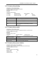
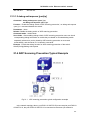
2.1.1.3 Power Supply
DCS-3950 series is designed to use modular switching power supplies. The power
input specification is shown below:
Nominal Input Voltage: AC: 100 ~ 240 VAC,
Frequency: 50-60Hz
Total power consumption: ≤30W
Before powering on the power supply, please check the power input to ensure proper
grounding of the power supply system. The input source for the switch should be reliable
and secure; a voltage adaptor can be used if necessary. The building’s circuit protection
system should include in the circuit a fuse or circuit-breaker of no greater than 240 V, 10 A.
It is recommended to use a UPS for more reliable power supplying
Caution!
Improper power supply system grounding, extreme fluctuation of the input source and
transients (or spikes) can result in larger error rate, or even hardware damage!
2.1.1.4 Preventing Electrostatic Discharge Damage
Static electric discharges can cause damage to internal circuits, even the entire
switch. Follow these guidelines for avoiding ESD damage
Ensure proper earth grounding of the device
Perform regular cleaning to reduce dust
Maintain proper temperature and humidity
Always wear an ESD wrist strap and antistatic uniform when in contact with circuit
boards
2.1.1.5 Anti-interference
All sources of interference, whether from the device/system itself or the outside
environment, will affect operations in various ways, such as capacitive coupling, inductive
coupling, electromagnetic radiation, common impedance (including the grounding system)
and cables/lines (power cables, signal lines, and output lines). The following should be
noted:
Precautions should be taken to prevent power source interference
Provide the system with a dedicated grounding, rather than sharing the grounding
with the electronic equipment or lightning protection devices
Keep away from high power radio transmitters, radar transmitters, and high frequency
strong circuit devices
Provide electromagnetic shielding if necessary
2.1.1.6 Rack Configuration
12
DCS-3950 series Ethernet switch manual
The dimensions of the switch designed to be mounted on a standard 19’’ rack, please
ensure good ventilation for the rack
Every device in the rack will generate heat during operation, therefore vent and fans
must be provided for an enclosed rack, and devices should not be stacked closely.
When mounting devices in an open rack, care should be taken to prevent the rack
frame from obstructing the switch ventilation openings. Be sure to check the
positioning of the switch after installation to avoid the aforementioned.
Caution!
If a standard 19’’ rack is not available, the switch can be placed on a clean level
desktop, leave a clearance of 10mm around the switch for ventilation, and do not place
anything on top of the switch
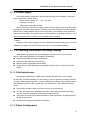
2.1.2 Installation Notice
Read through the installation instruction carefully before operating on the system.
Make sure the installation materials and tools are prepared. And make sure the
installation site is well prepared.
During the installation, users must use the brackets and screws provided in the
accessory kit. Users should use the proper tools to perform the installation. Users
should always wear antistatic uniform and ESD wrist straps. Users should use
standard cables and connecters.
After the installation, users should clean the site. Before powering on the switch,
users should ensure the switch is well grounded. Users should maintain the switch
regularly to extend the lifespan of the switch.
2.1.3 Security Warnings
Do not attempt to conduct the operations which can damage the switch or which can
cause physical injury.
Do not install, move or disclose the switch and its modules when the switch is in
operation.
Do not open the switch shell.
Do not drop metals into the switch. It can cause short-circuit.
Do not touch the power plug and power socket.
Do not place the tinder near the switch.
Do not configure the switch alone in a dangerous situation.
Use standard power sockets which have overload and leakage protection.
Inspect and maintain the site and the switch regularly.
Have the emergence power switch on the site. In case of emergence, switch off the
13
DCS-3950 series Ethernet switch manual
power immediately.
WARNING:
Situations which are dangerous or harmful include but are not limited to the following
items: creepage, over head power lines, broken down of power lines. If any
emergency happens, please firstly cut down the power supply, and then dial the local
emergency number.
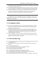
2.2 Installation Preparation
2.2.1 Verify the Packet Contents
The above contents are subject to the received packet contents.
2.2.2 Required Tools and Utilities
The required
utilities
tools
Connecting cable
and
z
Cross screwdrivers
z
Flat-blade screwdriver
z
wire clamp
z
Antistatic uniform
z
ESD wrist strap
z
Antistatic glove
z
Console cable and commutator
z
Standard Twisted-pair
z
RJ-45 pin
Table 2-4 The required tools and utilities
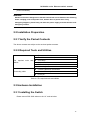
2.3 Hardware Installation
2.3.1 Installing the Switch
Please mount DCS-3950 series on the 19’’ rack as below
14
DCS-3950 series Ethernet switch manual
Fig 2-1
DCS-3950 series Rack-mounting
1. Attach the 2 brackets on the DCS-3950 series with screws provided in the
accessory kit.
2. Put the bracket-mounted switch smoothly into a standard 19’’ rack. Fasten
the DCS-3950 series to the rack with the screws provided. Leave enough
space around the switch for good air circulation.
Caution!
The brackets are used to fix the switch on the rack. They can’t serve as a bearing.
Please place a rack shelf under the switch. Do not place anything on top of the switch. Do
not block the blowholes on the switch to ensure the proper operation of the switch.
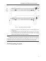
2.3.2 Connecting Console
15
DCS-3950 series Ethernet switch manual
DCS-3950 series provides a DB9 interface serial console port. The connection
procedure is listed below
Fig 2-2 Connecting Console to DCS-3950 series
1.
Please attach the console cable which is contained in the accessory kit to the
Console port of the switch.
2.
Connect the other side of the console cable to a character terminal (PC).
3.
Power on the switch and the character terminal. Configure the switch through the
character terminal.
Caution!
Please use the console cable and the console commutator of the switch. Don’t insert
in error to avoid break.
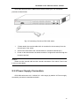
2.3.3 Power Supply Connection
DCS-3950 series uses 100~240VAC,50~60Hz supply by default. AC Power supply
connection procedure is described as below:
16
DCS-3950 series Ethernet switch manual
Fig 2-3 Attaching power cable to DCS-3950 series
1. Insert one end of the power cable provided in the accessory kit into the power source
socket (with overload and leakage protection), and the other end to the power socket in
the back panel of the switch.
2. Check the power status indicator in the front panel of the switch. The corresponding
power indicator should light. DCS-3950 series is self-adjustable for the input voltage. As
soon as the input voltage is in the range printed on the switch surface, the switch can
operate correctly.
3. When the switch is powered on, it executes self-test procedure and startups.
Caution!
The input voltage must be within the required range, otherwise the switch could
malfunction of be damaged. Do not open the switch shell without permission. It can cause
physical injury
17
DCS-3950 series Ethernet switch manual
Chapter 3 Setup Configuration
Setup configuration refers to the initial operation to the switch after the user
purchases the switch. For first-time users of the DCS-3950 series, this chapter provides a
very practical instruction. When using the CLI (command line interface), the user can type
setup under admin mode to enter the Setup configuration interface.
3.1 Setup Configuration
Setup configuration is done via menu selections, in which switch hostname, Vlan1
interface, Telnet service, Web service, and SNMP, can be configured.
3.2 Main Setup Menu
Before entry into the main menu, the following screen will be displayed to prompt the
user to select a preferred interface language. English users should choose ‘0’ to enter the
English interface, while Chinese users can choose ‘1’ to view the interface in Chinese.
Please select language
[0]: English
[1]: Chinese
Selection (0|1)[0]:
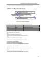
The main Setup configuration menu is listed below:
Configure menu
[0]: Config hostname
[1]: Config interface-Vlan1
[2]: Config telenet-server
[3]: Config web-server
[4]: Config SNMP
[5]: Exit setup configuration without saving
[6]: Exit setup configuration after saving
Selection number:
3.3 Setup Submenu
3.3.1 Configuring switch hostname
Select ‘0’ in the Setup main menu and press Enter, the following screen appears:
Please input the host name [switch]:
Note: the hostname entered should be less than 30 characters. If the user presses
18
DCS-3950 series Ethernet switch manual
Enter without input, the hostname will default to ‘switch’
3.3.2 Configuring Vlan1 Interface
Select ‘1’ in the Setup main menu and press Enter to start configuring the Vlan1
interface
Config Interface-Vlan1
[0]: Config interface-Vlan1 IP address
[1]: Config interface-Vlan1 status
[2]: Exit
Selection number:
Select ‘0’ in the Vlan1 interface configuration menu and press Enter, the following
screen appears
Please input interface-Vlan1 IP address (A.B.C.D):
When the user enters valid IP address for Vlan1 interface and presses Enter, the following
screen will appear:
Please input interface-Vlan1 mask [255.255.255.0]:
Select ‘1’ in the Vlan1 interface configuration menu and press Enter, the following
screen will appear:
Open interface-Vlan1 for remote configuration ? (y/n) [y]:
When the switch is booted for the first time, the Vlan1 interface is disabled by default.
In order to enable the vlan1 interface, ‘y’ or ENTER should be entered.
Select ‘2’ in the Vlan1 interface configuration menu will return to the Setup main
menu.
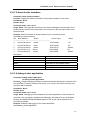
3.3.3 Telnet Server Configuration
Select ‘2’ in the Setup main menu and press Enter to start configuring the Telnet
server, the follow appears:
Configure telnet server
[0]: Add telnet user
[1]: Config telnet server status
[2]: Exit
Selection number:
Select ‘0’ in the Telnet server configuration menu and press Enter, the following
screen appears:
Please input the new telnet user name:
Note: the valid username length is 1 to 16 characters. When the user enters a valid
username and presses Enter, the following screen appears
19
DCS-3950 series Ethernet switch manual
Please input the new telnet user password:
Notice: The valid length for the password should be between 1 and 8 characters. After
user name and password are configured correctly, system configuration shell will be
prompted.
Select ‘1’ in the Telnet server configuration menu and press Enter, the following screen
appears:
Enable switch telnet-server or no? (y/n) [y]:
Type ‘y’ and press Enter, or just press Enter to enable Telnet service, type ‘n’ and
press Enter to disable Telnet service. The Telnet server configuration menu appears.
Select ‘2’ in the Telnet server configuration menu will return to the Setup main menu.
3.3.4 Configuring Web Server
Select ‘3’ in the Setup main menu and press Enter to start configuring the Web server,
the follow appears:
Configure web server
[0]: Add webuser
[1]: Config web server status
[2]: Exit
Selection number:
Select ‘0’ in the Web server configuration menu and press Enter, the following screen
appears:
Please input the new web user name:
Note: the valid username length is 1 to 16 characters. When the user enters a valid
username and presses Enter, the following screen appears
Please input the new web user password:
Note: the valid password length is 1 to 8 characters. After configuring the username
and password, the menu will return to the Web server configuration section
Select ‘1’ in the Web server configuration menu and press Enter, the following screen
appears:
Enable switch web-server or no?(y/n) [y]:
Type ‘y’ and press Enter, or just press Enter to enable Web service, type ‘n’ and press
Enter to disable Web service. The Web server configuration menu appears.
Select ‘2’ in the Telnet server configuration menu will return to the Setup main menu.
20
DCS-3950 series Ethernet switch manual
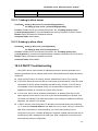
3.3.5 Configuring SNMP
Select ‘4’ in the Setup main menu and press Enter to start configuring SNMP, the
following appears
Configure SNMP
[0]: Config SNMP-server read-write community string
[1]: Config SNMP-server read-only community string
[2]: Config traps-host and community string
[3]: Config SNMP-server status
[4]: Config SNMP traps status
[5]: Add SNMP NMS security IP address
[6]: Exit
Selection number:
Select ‘0’ in SNMP configuration menu and press Enter, the following screen appears:
Please input the read-write access community string[private]:
Note: the valid length for a read-write access community string is 1 to 255 characters; the
default value is ‘private’. When a valid read-write access community string is entered,
pressing Enter returns you to the SNMP configuration menu.
Select ‘1’ in the SNMP configuration menu and press Enter, the following screen will
appear:
Please input the read-only access community string[public]:
Note: the valid length for a read-only access community string is 1 to 255 characters;
the default value is ‘public’. When a valid read-only access community string is entered,
press Enter returns to the SNMP configuration menu.
Select ‘2’ in the SNMP configuration menu and press Enter, the following screen will
appear:
Please input traps-host IP address (A.B.C.D):
When the user enters a valid IP address for Traps host and presses Enter, the
following appears:
Please input traps community string[public]:
Note: the valid length for a traps community string is 1 to 255 characters, the default
value is ‘public’. When a valid traps community string is entered, press Enter returns to the
SNMP configuration menu.
Select ‘3’ in the SNMP configuration menu and press Enter, the following screen will
appear:
21
DCS-3950 series Ethernet switch manual
Enable SNMP-server? (y/n) [y]:
Type ‘y’ and press Enter, or just press Enter to enable SNMP service, type ‘n’ and
press Enter to disable SNMP service. The SNMP configuration menu appears.
Select ‘4’ in the SNMP configuration menu and press Enter, the following screen will
appear:
Enable SNMP-traps ? (y/n) [y]:
Type ‘y’ and press Enter, or just press Enter to enable SNMP Traps, type ‘n’ and press
Enter to disable SNMP traps. The SNMP configuration menu appears.
Select ‘5’ in the SNMP configuration menu and press Enter, the following screen
appears:
Please input the new NMS IP address (A.B.C.D):
When a valid secure IP address (es) for SNMP management workstation is entered,
press Enter to return to the SNMP configuration menu.
Selecting ‘6’ in the SNMP configuration menu will return to the Setup main menu.
3.3.6 Exiting Setup Configuration Mode
Select ‘5’ in the Setup main menu to exit the Setup configuration mode without saving
the configurations made.
Selecting ‘6’ in the Setup main menu exits the Setup configuration mode and saves
the configurations made. This is equivalent to running the Write command. For instance, if
under the Setup configuration mode, the user sets a Telnet user and enables Telnet
service, and selects ‘5’ to exit Setup main menu. User will be able to configure the switch
through Telnet from a terminal.
When exiting the Setup configuration mode, the CLI configuration interface appears.
Configuration commands and syntaxes will be described in detail in later chapters.
22
DCS-3950 series Ethernet switch manual
Chapter 4 Switch Management
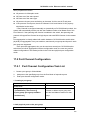
4.1 Management Options
After purchasing the switch, the user needs to configure the switch for network
management. DCS-3950 series provides two management options: in-band management
and out-of-band management.
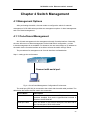
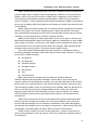
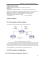
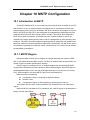
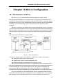
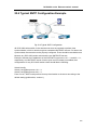
4.1.1 Out-of-band Management
Out-of-band management is the management through Console interface. Generally,
the user will use out-of-band management for the initial switch configuration, or when
in-band management is not available. For instance, the user must assign an IP address to
the switch via the Console interface to be able to access the switch through Telnet.
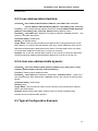
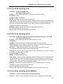
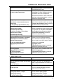
The procedures for management via Console interface are listed below:
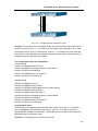
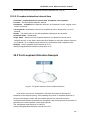
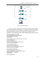
Step 1: setting up the environment:
Connect with serial port
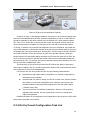
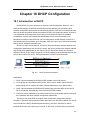
Fig 4-1 Out-of-band Management Configuration Environment
The serial port (RS-232) is connected to the switch with the serial cable provided. The
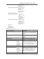
table below lists all the devices used in the connection.
Device Name
Description
PC machine
Has functional keyboard and RS-232, with terminal
emulator installed, such as the HyperTerminal included in
Windows 9x/NT/2000/XP.
Serial port cable
One end attach to the RS-232 serial port, the other end to
the Console port of DCS-3950 series.
DCS-3950
Functional Console port required.
23
DCS-3950 series Ethernet switch manual
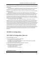
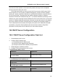
Step 2 Entering HyperTerminal.
Open the HyperTerminal included in Windows after the connection established.
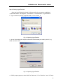
1) Click Start menu - All Programs – Accessories – Communication - HyperTerminal.
2)Type a name for opening HyperTerminal, such as ‘Switch_A’.
Fig 4-2 Opening HyperTerminal
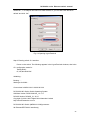
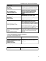
3)In the ‘Connecting with’ drop-list, select the RS-232 serial port used by the PC, e.g.
COM1, and click ‘OK’.
Fig 4-3 Opening HyperTerminal
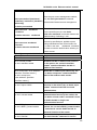
4)COM1 property appears, select ‘9600’ for ‘Baud rate’, ‘8’ for ‘Data bits’, ‘none’ for ‘Parity
24
DCS-3950 series Ethernet switch manual
checksum’, ‘1’ for stop bit and ‘none’ for traffic control; or, you can also click ‘Revert to
default’ and click ‘OK’.
Fig 4-4 Opening HyperTerminal
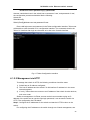
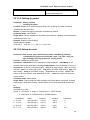
Step 3 Entering switch CLI interface:
Power on the switch. The following appears in the HyperTerminal windows, that is the
CLI configuration mode for
Testing RAM...
67,108,864 RAM OK.
Initializing...
Booting......
Starting at 0x10000...
Current time is MON JAN 01 00:00:00 2001
DCS-3950-28C Series Switch Operating System
SoftWare Version DCRS-5200-28_1.2.17.0
DCNOS Version DCNOS_5.1.35.47
Copyright (C) 2001-2007 Digital China Networks Limited
http://www.dcnetworks.com.cn
DCS-3950-28C Switch (88E6218-133M) processor
28 Ethernet/IEEE 802.3 interface(s)
25
DCS-3950 series Ethernet switch manual
Switch>
The user can now enter commands to manage the switch. For a detailed description for
the commands, please refer to the following chapters.
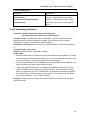
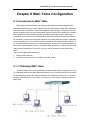
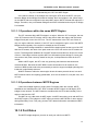
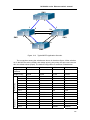
4.1.2 In-band Management
In-band management refers to the management by logging into the switch using Telnet.
In-band management enables the function of managing the switch for some devices
attached to the switch. In the case when in-band management fails due to switch
configuration changes, out-of-band management can be used for configuring and
managing the switch.
4.1.2.1 Management via Telnet
To manage the switch with Telnet, the following conditions should be met:
1) Switch has an IP address configured;
2) The host IP address (Telnet client) and the switch’s VLAN interface IP address is
in the same network segment.
3) If not 2), Telnet client can connect to an IP address of the switch via other devices,
such as a router.
DCS-3950 series are Layer 2 switch that can be configured with several IP addresses.
The following example assumes the shipment status of the switch, where only VLAN1
exists in the system.
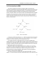
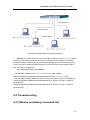
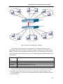
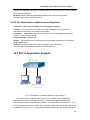
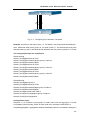
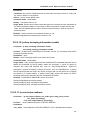
The following describes the steps for a Telnet client to connect to the switch’s VLAN1
interface by Telnet.
26
DCS-3950 series Ethernet switch manual
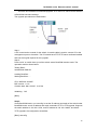
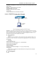
Fig 4-5 Manage the switch by Telnet
Step 1: Configure the IP addresses for the switch
First is the configuration of host IP address, which should be within the same network
segment as the switch VLAN1 interface IP address. Suppose the switch VLAN interface IP
address 10.1.128.251/24, and then a possible host IP address is 10.1.128.25/24. Run
‘ping 10.1.128.251’ from the host and verify the result, check for reasons if ping fails.
The IP address configuration commands for VLAN1 interface DCS-3950 series are
listed below. Before in-band management, the switch must be configured with an IP
address by out-of-band management (i.e. Console mode), The configuration commands
(All switch configuration prompts are assumed to be ‘switch’ hereafter if not otherwise
specified):
Switch>
Switch>en
Switch#config
Switch(Config)#interface vlan 1
Switch(Config-If-Vlan1)#ip address 10.1.128.251 255.255.255.0
Switch(Config-If-Vlan1)#no shutdown
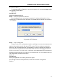
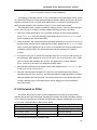
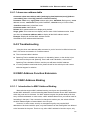
Step 2:
Run Telnet Client program
Fig 4-6 Run telnet client program included in Windows
Run Telnet client program included in Windows with the specified Telnet target
Step 3:
Login to the switch
Login in to the Telnet configuration interface. Valid login name and password is
required, otherwise the switch will reject Telnet access. This is a method to protect the
switch from unauthorized access. If no authorized Telnet user has been configured,
nobody can connect to the Telnet CLI configuration interface. As a result, when Telnet is
enabled for configuring and managing the switch, username and password for authorized
Telnet users must be configured with the following command:
27
DCS-3950 series Ethernet switch manual
telnet-user <user> password {0|7} <password>
Assume a authorized user in the switch has a username of ‘test’, and password of ‘test’,
the configuration procedure should be like the following:
Switch>en
Switch#config
Switch(Config)#telnet-user test password 0 test
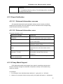
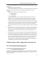
Enter valid login name and password in the Telnet configuration interface, Telnet user
will be able to enter the switch’s CLI configuration interface. The commands used in the
Telnet CLI interface after login are the same as in that in the Console interface.
Fig 4-7 Telnet Configuration Interface
4.1.2.2 Management via HTTP
To manage the switch via HTTP, the following conditions should be meet:
1) Switch has an IP address configured;
2) The host IP address and the switch’s VLAN interface IP address is in the same
network segment.
3) If not 2), Telnet client can connect to an IP address of the switch via other devices,
such as a router.
Similar to management via Telnet, as soon as the host succeeds to ping an IP
address of the switch and to type the right login password, it can access the switch via
HTTP. The configuration list is as below:
Step 1: Configure the IP addresses for the switch and start the HTTP function on the
switch.
For configuring the IP address on the switch through out-of-band management, see
28
DCS-3950 series Ethernet switch manual
the relevant chapter.
To enable the WEB configuration, users should type the CLI command ip http server
in the global mode as below:
Switch>en
Switch#config
Switch(Config)#ip http server
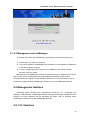
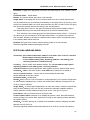
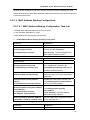
Step 2: Run HTTP protocol on the host.
Open the Web browser on the host and type the IP address of the switch. Or run
directly the HTTP protocol on the Windows. For example, the IP address of the switch is
‘10.1.128.251’.
Fig 4-8 Run HTTP Protocol
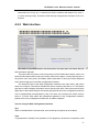
Step 3: Logon to the switch
To logon to the HTTP configuration interface, valid login user name and password are
required; otherwise the switch will reject HTTP access. This is a method to protect the
switch from the unauthorized access. Consequently, in order to configure the switch via
HTTP, username and password for authorized HTTP users must be configured with the
following command in the global mode: web-user <user> password {0|7} <password>
Suppose an authorized user in the switch has a username as ‘test’, and password as ‘test’.
The configuration procedure is as below:
Switch>en
Switch#config
Switch(Config)#web-user admin password 0 digital
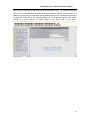
Input the right username and password, and then the main Web configuration
interface.
29
DCS-3950 series Ethernet switch manual
4.1.2.3 Management via LinkManager
To manage the switch with LinkManager, the following conditions should be met:
1) Switch has an IP address configured
2) The host IP address (LinkManager) and the switch’s VLAN interface IP address is
in the same network segment.
3) If not 2), LinkManager can connect to an IP address of the switch via other
devices, such as a router.
Management via LinkManager, the host succeeds to ping an IP address of the switch,
then run the switch, LinkManager network management software will be found by
DCS-3950 series,and operate it with read-write permission ,For more details on how to
configure the switch through LinkManager, please refer to the LinkManager Manual.
4.2 Management Interface
DCS-3950 series provide three management interfaces: CLI ( Command Line
Interface), Web interface, LinkManager network management software。Details about CLI
interface and Web interface will be presented as below. And for anything about
LinkManager, please refer to the LinkManager Manual.
4.2.1 CLI Interface
30
DCS-3950 series Ethernet switch manual
CLI interface is familiar to most users. As aforementioned, both out-of-band
management and Telnet login are all performed through CLI interface to manage the
switch.
CLI Interface is supported by Shell program, which consists of a set of configuration
commands. Those commands are categorized according to their functions in switch
configuration and management. Each category represents a different configuration mode.
The Shell for the switch is described below:
z
Configuration Modes
z
Configuration Syntax
z
Shortcut keys
z
Help function
z
Input verification
z
Fuzzy match support
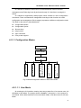
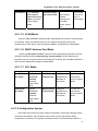
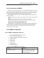
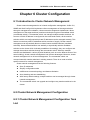
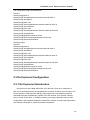
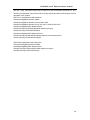
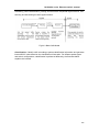
4.2.1.1 Configuration Modes
User Mode
Admin Mode
ACL configuration
mode
Route configuration
mode
DHCP address pool
configuration mode
Vlan Mode
Interface Mode
Global Mode
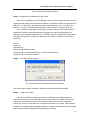
Fig 4-9 Shell Configuration Modes of DCS-3950 series
4.2.1.1.1 User Mode
On entering the CLI interface, entering user entry system first. If as common user, it is
defaulted to User Mode. The prompt shown is ‘Switch>‘, the symbol ‘>‘ is the prompt for
User Mode. When exit command is exit under Admin Mode, it will also return to the User
Mode.
31
DCS-3950 series Ethernet switch manual
Under User Mode, no configuration to the switch is allowed, only clock time and
version information of the switch can be queries.
4.2.1.1.2 Admin Mode
When enable command is used under User Mode,To Admin Mode sees the following:
In user entry system, if as Admin user, it is defaulted to Admin Mode. Admin Mode prompt
‘Switch#’ can be entered under the User Mode by running the enable command and
entering corresponding access levels admin user password, if a password has been set.
Or, when exit command is run under Global Mode, it will also return to the Admin Mode.
DCS-3950 series Switch also provides a shortcut key sequence ‘Ctrl+z’, this allows an
easy way to exit to Admin Mode from any configuration mode (except User Mode).
Under Admin Mode, the user can query the switch configuration information,
connection status and traffic statistics of all ports; and the user can further enter the Global
Mode from Admin Mode to modify all configurations of the switch. For this reason, a
password must be set for entering Admin mode to prevent unauthorized access and
malicious modification to the switch.
4.2.1.1.3 Global Mode
Type the config command under Admin Mode will enter the Global Mode prompt
‘Switch(Config)#’. Use the exit command under other configuration modes such as
Interface Mode, VLAN mode will return to Global Mode.
The user can perform global configuration settings under Global Mode, such as MAC
Table, Port Mirroring, VLAN creation, IGMP Snooping start, GVRP and STP, etc. And the
user can go further to Interface Mode for configuration of all the interfaces.
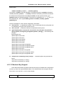
4.2.1.1.4 Interface Mode
Use the interface command under Global Mode can enter the interface mode
specified. DCS-3950 series Switch provides three interface type: VLAN interface, Ethernet
port and port-channel, and accordingly the three interface configuration modes.
Interface
Type
Entry
Prompt
Operates
Exit
VLAN
Interface
Type interface
vlan <Vlan-id>
command under
Global Mode.
Switch(Config-IfVlanx)#
Configure
switch IPs, etc
Use the exit
command to
return to
Global Mode.
Ethernet Port
Type interface
ethernet
<interface-list>
command under
Global Mode.
Switch(Configethernetxx)#
Configure
supported
duplex mode,
speed, etc.
of Ethernet
Port.
Use the exit
command to
return to
Global Mode.
32
DCS-3950 series Ethernet switch manual
port-channel
Type interface
port-channel
<port-channel-nu
mber> command
under Global
Mode.
Switch(Config-ifport-channelx)#
Configure
port-channel
related
settings such
as duplex
mode, speed,
etc.
Use the exit
command to
return to
Global Mode.
4.2.1.1.5 VLAN Mode
Using the vlan <vlan-id> command under Global Mode can enter the corresponding
VLAN Mode. Under VLAN Mode the user can configure all member ports of the
corresponding VLAN. Run the exit command to exit the VLAN Mode to Global Mode
4.2.1.1.6 DHCP Address Pool Mode
Type the ip dhcp pool <name> command under Global Mode will enter the DHCP
Address Pool Mode prompt ‘Switch(Config-<name>-dhcp)#’. DHCP address pool
properties can be configured under DHCP Address Pool Mode. Run the exit command to
exit the DHCP Address Pool Mode to Global Mode.
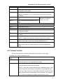
4.2.1.1.7 ACL Mode
ACL type
Entry
Prompt
Operates
Exit
Standard IP
ACL Mode
Type ip
access-list
standard
command
under Global
Mode.
Switch(Config
-Std-Nacl-a)#
Configure
parameters for
Standard IP
ACL Mode
Use the ‘exit’
command to
return to Global
Mode.
Extended IP
ACL Mode
Type ip
access-list
extanded
command
under Global
Mode.
Switch(Config
-Ext-Nacl-b)#
Configure
parameters for
Extended IP
ACL Mode
Use the ‘exit’
command to
return to Global
Mode.
4.2.1.2 Configuration Syntax
DCS-3950 series Switch provides various configuration commands. Although all the
commands are different, they all abide by the syntax for DCS-3950 series Switch
configuration commands. The general commands format of DCS-3950 series Switch is
33
DCS-3950 series Ethernet switch manual
shown below:
cmdtxt <variable> { enum1 | … | enumN } [option]
Conventions: cmdtxt in bold font indicates a command keyword; <variable> indicates a
variable parameter; {enum1 | … | enumN } indicates a mandatory parameter that should
be selected from the parameter set enum1~enumN; and the square bracket ([ ]) in
[option] indicate an optional parameter. There may be combinations of ‘< >‘, ‘{ }’ and ‘[ ]’ in
the command line, such as [<variable>],{enum1 <variable>| enum2}, [option1
[option2]], etc.
Here are examples for some actual configuration commands:
z show version, no parameters required. This is a command with only a keyword and
no parameter, just type in the command to run.
z vlan <vlan-id>, parameter values are required after the keyword.
z
speed-duplex {auto | force10-half | force10-full | force100-half | force100-full |
{{force1g-half | force1g-full} [nonegotiate [master | slave]] } },the followings are
possible:
speed-duplex auto
speed-duplex force10-half
speed-duplex force10-full
speed-duplex force100-half
speed-duplex force100-full
speed-duplex force1g-half
speed-duplex force1g-half nonegotiate
speed-duplex force1g-half nonegotiate master
speed-duplex force1g-half nonegotiate slave
speed-duplex force1g-full
speed-duplex force1g-full nonegotiate
speed-duplex force1g-full nonegotiate master
speed-duplex force1g-full nonegotiate slave
z
snmp-server community {ro|rw} <string>, command options are presented as
below:
snmp-server community ro <string>
snmp-server community rw <string>
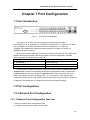
4.2.1.3 Shortcut Key Support
DCS-3950 series switch provides several shortcut keys to facilitate user configuration,
such as up, down, left, right and Blank Space. If the terminal does not recognize Up and
Down keys, ctrl +p and ctrl +n can be used instead.
Key(s)
Function
34
DCS-3950 series Ethernet switch manual
Back Space
Delete a character before the cursor, and the cursor moves back.
Up ‘↑’
Show previous command entered. Up to ten recently entered
commands can be shown.
Down ‘↓’
Show next command entered. When use the Up key to get previously
entered commands, you can use the Down key to return to the next
command
Left ‘←’
The cursor moves one character to the
left.
Right ‘→’
The cursor moves one character to the
right.
Ctrl +p
The same as Up key ‘↑’.
Ctrl +n
The same as Down key ‘↓’.
Ctrl +b
The same as Left key ‘←’.
Ctrl +f
The same as Right key ‘→’.
Ctrl +z
Return to the Admin Mode directly from the other configuration modes
( except User Mode).
Ctrl +c
Break the ongoing command process, such as ping or other command
execution.
Tab
When a string for a command or keyword is entered, the Tab can be
used to complete the command or keyword if there is no conflict.
/
Perform command of previous list,such as perform show command of
admin mode under config mode: Switch(Config)#/show run
//
Perform command of previous list,such as perform show command of
admin mode under port config:Switch(Config-Port-Range)#//show
clock.
You can use the Left and
Right key to modify an
entered command.
4.2.1.4 Help Function
There are two ways in DCS-3950 series Switch for the user to access help
information: the ‘help’ command and the ‘?’.
Access to
Help
Usage and function
Help
Under any command line prompt, type in ‘help’ and press Enter will get
a brief description of the associated help system.
‘?’
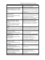
1.Under any command line prompt, enter ‘?’ to get a command list of the
current mode and related brief description.
2.Enter a ‘?’ after the command keyword with a embedded space. If the
position should be a parameter, a description of that parameter type,
scope, etc, will be returned; if the position should be a keyword, then a
set of keywords with brief description will be returned; if the output is
‘<cr>‘, then the command is complete, press Enter to run the
35
DCS-3950 series Ethernet switch manual
command.
3.A ‘?’ immediately following a string. This will display all the commands
that begin with that string.
4.2.1.5 Input Verification
4.2.1.5.1 Returned Information: success
All commands entered through keyboards undergo syntax check by the Shell.
Nothing will be returned if the user entered a correct command under corresponding
modes and the execution is successful.
4.2.1.5.2 Returned Information: error
Returned Information: error
Output error message
Explanation
Unrecognized command or illegal
parameter!
The entered command does not exist, or there
is error in parameter scope, type or format.
Ambiguous command
At least two interpretations is possible basing
on the current input.
Invalid command or parameter
The command is recognized, but no valid
parameter record is found.
This command is not exist in current
mode
The command is recognized, but this
command can not be used under current
mode.
Please configure precursor
command ‘*’ at first !
The command is recognized, but the
prerequisite command has not been
configured.
syntax error : missing '‘' before the
end of command line!
Quotation marks are not used in pairs.
4.2.1.6 Fuzzy Match Support
DCS-3950 series switch shell support fuzzy match in searching command and
keyword. Shell will recognize commands or keywords correctly if the entered string
causes no conflict.
For example:
1. For command ‘show interfaces status ethernet 1’, typing ‘sh in e 1’ will work
2. However, for command ‘show running-config’, the system will report a ‘> Ambiguous
36
DCS-3950 series Ethernet switch manual
command!’ error if only ‘sh r’ is entered, as Shell is unable to tell whether it is ‘show r’
or ‘show running-config’. Therefore, Shell will only recognize the command if ‘sh ru’ is
entered.
4.2.2 Web Interface
The Web configuration interface has three parts: the upper part, the bottom left part
and the bottom right part.
The upper part is a picture of the front panel of a DCS-3950 series switch, which can
show the connection state of each port via the LEDs on the panel. If users click the port on
the picture of the front panel, the statistic traffic information of each port will be displayed
at the bottom right part of the Web configuration interface.
The bottom left part of the Web configuration interface is the main menu, with which
users can configure, control and maintain the switch, monitor ports and so on. The bottom
right part is used to display information and to interact with users. When the users click the
upper part or the bottom left part, the bottom right part will show the configuration interface
of the corresponding menu(submenu), then, the users can configure the switch as they
want to. To know more about the parameters appeared in the configuration interface,
please refer to the configuration introduction in relative chapters.
Tips on using the Web Configuration Interface
Tip 1
IE6.0 or later/800*600 is recommened, and JavaScript is required to be enabled.
Tip 2
To guarantee the validity of the operation of CGI programs, the brower is required to read
37
DCS-3950 series Ethernet switch manual
new stuff from the server every time instead of the system cache. The following steps will
show you how to realize this: Choose the Tools(T)->Internet Options from the menu of a
Website or right click the IE browser on the desktop and choose Properities to enter the
configuration interface. In the ‘Settings’ dialog box of ‘Temporary Internet File’, under
‘Check for newer versions of stored pages’, click ‘Every visit to the page’.
38
DCS-3950 series Ethernet switch manual
Chapter 5 Basic Switch Configuration
5.1 Basic Switch Configuration Command List
Basic switch configuration includes commands for entering and exiting the admin
mode, commands for entering and exiting interface mode, for configuring and displaying
the switch clock, for displaying the version information of the switch system, etc.
Caution!
By default, the host name of a switch and the command line prompt is the same as the
type of the switch. In this chapter, “Switch” is used to represent general command line
prompt.
5.1.1 clock set
Command: clock set <HH:MM:SS> <YYYY/MM/DD>
Function: Configure data and time setting
Parameter: <HH:MM:SS >current time,HH: The number range 0~23, MM and SS:The
number range 0~59;< YYYY.MM.DD >current year/month/day, YYYY:The number range
1970~2100, MM: The number range 1~12, DD: The number range 1~31.
Command mode: Admin Mode
Default: The default date is 2001—Jan-01 0:0:0.
Usage Guide: system clock of the switch will be reset when power is down. The system
clock should be re-initialized through this command after power reset.
Example: Set the system clock to Aug. 1st, 2002, commands should be entered as below:
Switch#clock set 23:0:0 2002.8.1
Relative command: show clock
5.1.2 config
Command: config [terminal]
Function: Convert from admin mode to global mode.
Parameter: [terminal] to configure
Command mode: Admin Mode
Example:
Switch#config
39
DCS-3950 series Ethernet switch manual
5.1.3 exec timeout
Command: exec timeout <minutes >
Function: Configure the overtime of quitting privileged configuration mode.
Parameter: < minute >is time; the unit is minute(The range 0~300)
Command mode: Global Mode
Default: The default time is 5 minutes.
Usage Guide: For security reason, a timer can be set for the privileged user’s login
session through this command. And the timer will be enabled when there are no
operations in the login session. When timeout happens, the privileged session will be
terminated automatically. User name and password should be entered again in order to
re-enable the privilege login session. If the timer is set to 0, it will be disabled.
Example: Set the time out limits to 6 minutes:
Switch(Config)#exec timeout 6
5.1.4 exit
Command: exit
Function: Quit from the current mode quit and return the previous mode. By this
command, users being in global mode will return to admin configuration mode; users
being admin mode will return to user mode.
Command mode: All Modes
Example:
Switch#exit
Switch>
5.1.5 help
Command: help
Function: Output brief description of the command interpreter help system.
Command mode: All Modes
Usage Guide: An instant online help provided by the switch. Help command displays
information about the whole help system, including complete help and partial help. The
user can type in any time to get online help.
Example:
Switch>help
enable
exit
help
show
-- Enable Privileged mode
-- Exit telnet session
-- help
-- Show running system information
40
DCS-3950 series Ethernet switch manual
5.1.6 ip host
Command: ip host <hostname> <ip_addr>
no ip host <hostname>
Function: Set the mapping relationship between the host and IP address; the ‘no ip host’
parameter of this command will delete the mapping.
Parameter: <hostname> is the host name, up to 15 characters are allowed; <ip_addr> is
the corresponding IP address for the host name, takes a dot decimal format.
Command mode: Global Mode
Usage Guide: Maps between hostname and ip address can be set through this command,
for operations such as ‘ping <host>‘.
Example: Set 200.121.1.1 as the ip address of a host named beijing:
Switch(Config)#ip host beijing 200.121.1.1
Relative command: telnet、ping、traceroute
5.1.7 ip http server
Command: ip http server
no ip http server
Function: Enable the Web configuration; the ‘no no ip http server’ command is used to
disable the Web configuration.
Command mode: Global Mode.
Usage Guide: Web interface can be a choice to configure the switch through this
command. Its simple, easy to use and easy to understand. This command has the same
effect as choosing option 2 in the Setup configuration mode.
Example: Enable the web configuration interface:
Switch(Config)#ip http server
Relative Command: web-user.
5.1.8 hostname
Command: hostname <hostname>
Function: Set the prompt in the switch command line interface.
Parameter:<hostname> is the string for the prompt, up to 30 characters are allowed.
Command mode: Global Mode
Default: The default prompt is related to DCS-3950 series switch type.
Usage Guide: Shell prompt can be changed and customized through this command.
Example: Customize the promption as Test:
Switch(Config)#hostname Test
Test(config)#
41
DCS-3950 series Ethernet switch manual
5.1.9 reload
Command: reload
Function: Warm reset the switch.
Command mode: Admin Mode
Usage Guide: The switch can be rebooted through this command without resetting the
power.
5.1.10 set default
Command: set default
Function: Reset the switch to factory settings.
Command mode: Admin Mode
Usage Guide: The switch will be reset to the factory state through this command. All the
configurations will be reset after system reboot.
Notice: the write command should be issued after the above command, in order to save
the results. Switch configurations will be reset to factory mode after system reboot.
Example:
Switch#set default
Are you sure? [Y/N] = y
Switch#write
Switch#reload
5.1.11 setup
Command: setup
Function: Enter the Setup Mode of the switch.
Command mode: Admin Mode
Usage Guide: Configuration such as Ip addressed and web services can be done through
this command in the Setup mode.
5.1.12 language
Command: language {chinese|english}
Function: Set the language for displaying the help information.
Parameter: Chinese for Chinese display; English for English display.
Command mode: Admin Mode
Default: The default setting is English display.
Usage Guide: Language for the system can be customized through this command
according to the requirement. System language will be reset to English by default.
42
DCS-3950 series Ethernet switch manual
5.1.13 web-user
Command:web-user <username> password {0|7} <password>
no web-user <username>
Function:Set a username and its password for a Web client; the ‘no web-user
<username>‘ command is used to delete this Web client.
Parameters:<username>is an authorized username to do Web access, whose length
should be no more than 16 characters; <password> is the access password, no longer
than 8 characters; 0|7 respectively indicate to display the original or the encrypted
password.
Command mode:Global Mode.
Usage Guide: To prevent un-authorized users from accessing the web interface, user
names and passwords can be created for accessing the web interface through this
command.
Example: Create a user name Admin with switch as its password.
Switch(Config)#web-user Admin password 0 switch
Relative Command: ip http server
5.1.14 write
Command: write
Function: Save the currently configured parameters to the Flash memory.
Command mode: Admin Mode
Usage Guide: With this command, valid configurations can be preserved in the flash. And
system can recover its preserved configuration after system reset. This command has the
same effect as copy running-config startup-config
5.1.15 show cpu usage
Command:show cpu usage
Function:Display the CPU usage rate of the switch
Command mode: Admin Mode.
Usage Guide: load of the system can be presented through this command.
Example:
Switch#show cpu usage
Last 5 second CPU IDLE: 99%
Last 30 second CPU IDLE: 99%
Last 5 minute CPU IDLE: 99%
From running CPU IDLE: 99%
43
DCS-3950 series Ethernet switch manual
5.1.16 show tech-support
Command:show tech-support
Function: Collect tech-support information.
Command mode: Admin Mode.
Usage Guide: Information can be get through this command for determining the cause of
any system failure.
Example:
Switch#show tech-support
5.1.17 vendorcontact
Command:vendorcontact <information>
Function:Set vendor contact information in the switch.
Parameters:< information > is vendor contact information letters.
Command mode:Global Mode.
Usage Guide:The vendor contact information in this command can be telephone, fax,
etc.
Example:Set vendor contact 800-810-9119
Switch(Config)# vendorcontact 800-810-9119
5.1.18 vendorlocation
Command:vendorlocation <information>
Function:Set switch location information
Parameters:<information> is switch location information letters.
Command mode:Global Mode.
Usage Guide:Set switch location to China.
Switch(Config)#vendorlocation china
5.1.19 web-language
Command:web-language {chinese| english}
Function:Set web language.
Parameters:chinese: set web language to Chinese.
english: set web language to English.
Command mode:Global Mode.
Usage Guide:reset switch to make effective of web language.
Example:set web language to English:
Switch(Config)#web-language english
44
DCS-3950 series Ethernet switch manual
5.2 Monitor and Debug Command List
When the users configures the switch, they will need to verify whether the
configurations are correct and the switch is operating as expected, and in network failure,
the users will also need to diagnostic the problem. DCS-3950 series switch provides
various debug commands including ping, telnet, show and debug, etc. to help the users to
check system configuration, operating status and locate problem causes.
5.2.1 Ping
Command:ping
[<ip-addr>|<hostname>]
Function: the switch sends ICMP request packet to remote client device and checks the
communications between both sides is fine or not.
Parameter: <ip-addr>is destination host IP address, in dotted decimal notation.
<hostname> is destination host name,
number and letter constitute character
string.Blank is not allowed,the length of character string is from 1 to 30.
Default: send 5 ICMP request packets; the packet size is 56 bytes; timeout is 2 seconds.
Command mode: Admin Mode
Usage Guide: Interactive configuration mode is provided if the ping command is entered
without any parameters. Ping parameters can be set this way.
Example
Ex.1: To use the default options of ping.
Switch#ping 10.1.128.160
Type ^c to abort.
Sending 5 56-byte ICMP Echos to 10.1.128.160, timeout is 2 seconds.
...!!
Success rate is 40 percent (2/5), round-trip min/avg/max = 0/0/0 ms
For the above example, ping will be send from the switch to some device with
10.1.128.160 as its ip address. For the first three ICMP echo packets, the switch considers
the other side to be unreachable because the corresponding ICMP reply packets can not
be retrieved with 2 seconds after the echo packets are sent out. For the following two echo
packets, reply is retrieved correctly, so the success rate is 40%. Here, failure is denoted as
‘.’, while success is denoted as ‘!’.
Ex.2: Launch the ping command with customized parameters.
Switch#ping
Target IP address:10.1.128.160
Repeat count [5]:100
Datagram size in byte [56]:1000
Timeout in milli-seconds [2000]:500
Extended commands [n]:n
Parameters
Notes
protocol [IP]:
Protocol for the ping command.
45
DCS-3950 series Ethernet switch manual
Target IP address:
Ip address of the target device.
Repeat count [5]
Number of ping echo packets to be sent.
Default is 5.
Datagram size in byte [56]
Size of the ping echo packet in bytes.
Default is 56.
Timeout in milli-seconds [2000]:
Timeout for the reply packets in
milliseconds. Default is 2 seconds.
Extended commands [n]:
Whether need to change other option.
5.2.2 Telnet
5.2.2.1 Introduction to Telnet
Telnet is a simple remote terminal protocol for remote login. Using Telnet, the user
can login to a remote host with its IP address of hostname from his own workstation.
Telnet can send the user’s keystrokes to the remote host and send the remote host output
to the user’s screen through TCP connection. This is a transparent service, as to the user,
the keyboard and monitor seems to be connected to the remote host directly.
Telnet employs the Client-Server mode, the local system is the Telnet client and the
remote host is the Telnet server. DCS-3950 series switch can be either the Telnet Server
or the Telnet client.
When DCS-3950 series switch is used as the Telnet server, the user can use the
Telnet client program included in Windows or the other operation systems to login to
DCS-3950 series switch, as described earlier in the In-band management section. As a
Telnet server, DCS-3950 series switch allows up to 5 telnet client TCP connections.
And as Telnet client, using telnet command under Admin Mode allows the user to
login to the other remote hosts. DCS-3950 series switch can only establish TCP
connection to one remote host. If a connection to another remote host is desired, the
current TCP connection must be dropped.
5.2.2.2 Telnet Configuration Task List
1. Configuring Telnet Server
2. Telnet to a remote host from the switch
1. Configuration of Telnet Server
Command
Explanation
Global Mode
telnet-server enable
Enable the Telnet server function in the
46
DCS-3950 series Ethernet switch manual
no telnet-server enable
telnet-user <user-name> password
{0|7} <password>
no telnet-user <user-name>
switch: the ‘no telnet-server enable’
command disables the Telnet function.
Configure the username and password to
login to the switch through Telnet: the no
telnet-user <user-name> command
disables Telnet accredited user.
Configure the secure IP address to login
telnet-server securityip <ip-addr>
no telnet-server securityip <ip-addr>
authentication login {local|radius|local
radius|radius local}
no authentication login
to the switch through Telnet: the ‘no
telnet-server securityip
<ip-addr>‘ command deletes the
authorized Telnet secure address.
Configure validatory mode
long-distance login in
of
Admin Mode
Display debug information for Telnet
Monitor
no monitor
client login to the switch; the ‘no
monitor’ command disables the debug
information.
2. Telnet to a remote host from the switch
Command
Explanation
Admin Mode
telnet [<ip-addr>] [<port>]
Login to a remote host with the Telnet
client included in the switch.
5.2.2.3 Telnet Command List
5.2.2.3.1 authentication login
Command:authentication login {local | radius | local radius | radius local}
no authentication login
Function:Configure the Telnet Server to set the password authentication mode and
privilege of remote access users; the ‘no authentication login’ command is used to reset
it to the default authentication mode.
Default Setting:The default access authentication mode is local.
Command mode:Global Mode.
Usage Guide: When combined authentication is used, authentication method in the front
will be of the highest priorities. And the latter, the lower. If a user is approved by any
authentication method of higher priority, any authentication method of lower priority will be
ignored. To be noticed, when radius is used for authentication, AAA must be enabled, and
a dedicated radius server should be configured.
47
DCS-3950 series Ethernet switch manual
Example: Configure the authentication method for remote access to be radius.
Switch(Config)#authentication login radius
Relative Command:aaa enable,radius-server authentication host
5.2.2.3.2 monitor
Command: monitor
no monitor
Function:Make Telnet clients display debug information, and disable Console clients to
display debug information function. Use the ‘no’ command to disable Telnet client display
debug information function and restore Console client display debug information function.
Command mode: Admin Mode
Usage Guide: By default, any debug information will be output to the Console port of the
swich, but not the remote telnet session. With this command, debug information can be
redirected to the specified remote telnet session, but not the Console port or any other
telnet sessions.
Example: Enable debug information output through telnet sessions.
Switch#monitor
Relative Command:telnet-user
5.2.2.3.3 telnet
Command:telnet [<ip-addr>|<ip-host-name>] [<port>]
Parameter: <ip-addr> is the IP address of the remote host, shown in dotted decimal
notation;<hostname> is the name of the remote host,containing max 30
characters;<port> is the port number,ranging between 0~65535.
Command mode: Admin Mode
Usage Guide: This command is used to set up telnet configuration sessions through one
switch as the telnet client to another. When the switch is used as telnet client, only one
remote session can be setup at the same time. In order to connect to another host, any
existing TCP connections should be disconnected before the new connection is setup. To
disconnect any existing sessions, Please use ‘Ctrl + I’.
If no parameters are appended to the telnet command, interactive configuration mode will
be invoked.
Ex1: To telnet to a remote router named ROUTER with ip address as 20.1.1.1.
Switch#telnet 20.1.1.1 23
Trying 20.1.1.1...
Service port is 23
Connected to 20.1.1.1
login:123
password:***
DCR>
Ex2: Set the host name of a remote router ROUTER with ip address as 20.1.1.1 as aa.
48
DCS-3950 series Ethernet switch manual
Then telnet the remote host through the host name.
Switch#config
Switch(Config)#ip host aa 20.1.1.1
Switch(Config)#exit
Switch#telnet aa 23
Trying 20.1.1.1...
Service port is 23
Connected to 20.1.1.1
login:123
password:***
router>
Relative Command:ip host
5.2.2.3.4 telnet-server enable
Command::telnet-server enable
no telnet-server enable
Function: Enable the Telnet server function in the switch: the ‘no telnet-server enable’
command disables the Telnet function in the switch.
Default: Telnet server function is enabled by default.
Command mode: Global Mode
Usage Guide: This command can only be invoked within the Console port. And remote
telnet session to the switch can be enabled or disabled through this command.
Example: Disable the telnet server for the switch.
Switch(Config)#no telnet-server enable
5.2.2.3.5 telnet-server securityip
Command: telnet-server securityip <ip-addr>
no telnet-server securityip <ip-addr>
Function: Configure the secure IP address of Telnet client allowed to login to the switch;
the ‘no telnet-server securityip <ip-addr>‘ command deletes the authorized Telnet
secure address.
Parameter: <ip-addr> is the secure IP address allowed to access the switch, in dot
decimal format.
Default: no secure IP address is set by default.
Command mode: Global Mode
Usage Guide: IP address of telnet client to the switch is not restricted before secure IP
address is configured. Only the host in the secure IP address list can telnet to the remote
switch. Multiple security ip address can be configure at the same time.
Example: Set 192.168.1.21 as the secure ip address.
Switch(Config)#telnet-server securityip 192.168.1.21
49
DCS-3950 series Ethernet switch manual
5.2.2.3.6 telnet-user
Command:telnet-user <username> password {0|7} <password>
no telnet-user <username>
Function: Configure user names and passwords of Telnet clients. Use the ‘no
telnet-user <username>‘ command to remove the Telnet users.
Parameter: <username>is the Telnet client user name. The maximum length may not
exceed 16 characters; <password>is the login password, the maximum length may not
exceed 8 characters; 0|7 part means as passwords displayed not encrypted or
encrypted
Command mode: Global Mode
Default: The default system does not configure Telnet client user name and password.
Usage Guide: This command is used when the switch is configured as a telnet server.
Authenticated telnet users can be configured through this command. If no authenticated
users are configured, any telnet client can never configure the switch through telnet.
When the switch is configured as a telnet server, maximum of 5 telnet connections can be
maintained by the switch.
Example: Setup a telnet user who named Antony, and the password is switch.
Switch(Config)#telnet-user Antony password 0 switch
5.2.3 SSH
5.2.3.1 Introduction to SSH
SSH (Secure Shell) is a protocol which ensures a secure remote access connection
to network devices. It is based on the reliable TCP/IP protocol. By conducting the
mechanism such as key distribution, authentication and encryption between SSH server
and SSH client, a secure connection is established. The information transferred on this
connection is protected from being intercepted and decrypted. The switch meets the
requirements of SSH2.0. It supports SSH2.0 client software such as SSH Secure Client
and putty. Users can run the above software to manage the switch remotely.
The switch presently supports RSA authentication, 3DES cryptography protocol and
SSH user password authentication etc.
5.2.3.2 SSH Server Configuration Task List
1.
SSH Server Configuration
Command
Explanation
Global Mode
50
DCS-3950 series Ethernet switch manual
ssh-server enable
no ssh-server enable
ssh-user <user-name> password {0|7}
<password>
no ssh-user <user-name>
Enable SSH function on the switch; the
‘no ssh-server enable’ command
disables SSH function.
Configure the username and password of
SSH client software for logging on the
switch; the ‘no ssh-user
<user-name>‘ command deletes the
username.
Configure timeout value for SSH
ssh-server timeout <timeout>
no ssh-server timeout
authentication; the ‘no ssh-server
timeout’ command restores the default
timeout value for SSH authentication.
Configure the number of times for retrying
ssh-server authentication-retires <
authentication-retires>
no ssh-server authentication-retries
SSH authentication; the ‘no ssh-server
authentication-retries’ command
restores the default number of times for
retrying SSH authentication.
ssh-server host-key create rsa
modulus <moduls>
Generate the new RSA host key on the
SSH server.
Admin Mode
Display SSH debug information on the
monitor
no monitor
SSH client side; the ‘no monitor’
command stops displaying SSH debug
information on the SSH client side.
5.2.3.3 SSH Command List
5.2.3.3.1 ssh-server enable
Command: ssh-server enable
no ssh-server enable
Function: Enable SSH function on the switch; the ‘no ssh-server enable’ command
disables SSH function.
Command mode: Global Mode
Default: SSH function is disabled by default.
Usage Guide: SSH users should be configured and SSH service should be enabled
before SSH clients can connect to the switch.
Example: Enable the SSH service of the switch.
Switch(Config)#ssh-server enable
5.2.3.3.2 ssh-user
Command: ssh-user <username> password {0|7} <password>
51
DCS-3950 series Ethernet switch manual
no ssh-user <username>
Function: Configure the username and password of SSH client software for logging on
the switch; the ‘no ssh-user <user-name>‘ command deletes the username.
Parameter: <username> is SSH client username. It can’t exceed 16 characters;
<password> is SSH client password. It can’t exceed 8 characters; 0|7 stand for
unencrypted password and encrypted password.
Command mode: Global Mode
Default: There are no SSH username and password by default.
Usage Guide: Authenticated SSH clients are configured through this command. Any SSH
clients will not be able to connect to the switch with out the authentication. When the
switch configured as SSH server, maximum of 3 users can be configured. And maximum
of 3 concurrent SSH sessions can be setup.
Example: Setup a SSH client named switch, with its password as switch.
Switch(Config)#ssh-user switch password 0 switch
5.2.3.3.3 ssh-server timeout
Command: ssh-server timeout <timeout>
no ssh-server timeout
Function: Configure timeout value for SSH authentication; the ‘no ssh-server timeout’
command restores the default timeout value for SSH authentication.
Parameter: <timeout> is timeout value; valid range is 10 to 600 seconds.
Command mode: Global Mode
Default: SSH authentication timeout is 180 seconds by default.
Usage Guide: Timeout for authenticated SSH client can be set through this command.
Default is 180 seconds.
Example: Set the timeout for SSH authentication to be 240 seconds.
Switch(Config)#ssh-server timeout 240
5.2.3.3.4 ssh-server authentication-retries
Command: ssh-server authentication-retries < authentication-retries >
no ssh-server authentication-retries
Function: Configure the number of times for retrying SSH authentication; the ‘no
ssh-server authentication-retries’ command restores the default number of times for
retrying SSH authentication.
Parameter: < authentication-retries > is the number of times for retrying authentication;
valid range is 1 to 10.
Command mode: Global Mode
Default: The number of times for retrying SSH authentication is 3 by default.
Usage Guide:
Example: Setup retry limits for authentications for SSH clients.
Switch(Config)#ssh-server authentication-retries 5
52
DCS-3950 series Ethernet switch manual
5.2.3.3.5 ssh-server host-key create rsa
Command:ssh-server host-key create rsa [modulus < modulus >]
Function: Generate new RSA host key
Parameter: modulus is the modulus which is used to compute the host key; valid range
is 768 to 2048. The default value is 1024.
Command mode: Global Mode
Default: The system uses the key generated when the ssh-server is started at the first
time.
Usage Guide: This command is used to create new security keys for the host. After the
key is created, SSH clients will have to use the key in order to communicate with the host.
If the configuration for the new key is preserved through the write command, the system
will use the key for host authentications. For encrypting and decrypting of the key is quite
time consuming, as well as some client does not support keys which are of modulus of
2048 bits, it is recommended to use the default modulus of 1024 bits for computation of
the keys for the efficiency and compatibilityreasons.
Example: Create a new key for the host.
Switch(Config)#ssh-server host-key create rsa
5.2.3.3.6 monitor
Command:monitor
no monitor
Function: Display SSH debug information on the SSH client side; at the same time
disable function of debug information in console,the ‘no monitor’ command stops
displaying SSH debug information on the SSH client side,enable function of debug
information in console
Command mode: Admin Mode
Usage Guide: By default, the debug information will be output to the Console port of the
switch but not the SSH login session if the debug information is enabled on the switch.
With this command, debug information can be redirected to the specified SSH login
session, but not the Console port or any other telnet or SSH login session.
Example: Enable debug information for the SSH client.
Switch#monitor
Relative Command: ssh-user
5.2.3.4 SSH Server Configuration Example
Scenario 1:
Requirement: Enable SSH server on the switch, and run SSH2.0 client software such
as secure shell client and putty on the terminal. Log on the switch by using the username
and password from the client.
Configure the IP address, add SSH user and enable SSH service on the switch.
SSH2.0 client can log on the switch by using the username and password to configure the
53
DCS-3950 series Ethernet switch manual
switch.
Switch(Config)#interface vlan 1
Switch(Config-Vlan-1)#ip address 100.100.100.200 255.255.255.0
Switch(Config-Vlan-1)#exit
Switch(Config)#ssh-user test password 0 test
Switch(Config)#ssh-server enable
5.2.3.5 SSH Monitor and Debug Command List
5.2.3.5.1 show ssh-user
Command:show ssh-user
Function:Display all the configured SSH usernames.
Command mode:Admin Mode.
Example:
Switch#show ssh-user
test
Relative Command:ssh-user
5.2.3.5.2 show ssh-server
Command:show ssh-server
Function:Display the state of SSH server (open or closed) and the information of users
who has already logged in.
Command mode:Admin Mode.
Example:
Switch#show ssh-server
ssh-server is enabled
connection version
state
user name
1
2.0
session started
test
Relative Command:ssh-server enable,no ssh-server enable
5.2.3.5.3 debug ssh-server
Command:debug ssh-server
no debug ssh-server
Function:Enable the debug information of SSH server. The ‘no debug ssh-server
‘ command is used to disable the debug information of SSH server.
Default:By default, the debug information is disabled.
Command mode:Admin Mode.
5.2.4 Traceroute
54
DCS-3950 series Ethernet switch manual
Command:traceroute {<ip-addr> | host <hostname> }[hops <hops>] [timeout
<timeout> ]
Function:This command is used to test the gateways passed by packets on their way
from sending equipment to destination equipment, in order to check whether the network
can be reached and to locate the fault of network.
Parameters:<ip-addr>is the IP address of the destination host, in dotted-decimal format;
<hostname>is the host name of the remote host. <hops> is the max number of passed
gateways allowed by Traceroute. <timeout>is the timeout value of packets, in millisecond,
ranging from 100 to 10000.
Default:The max number of passed gateways is set by default as 16, while the timeout
value is 2000 milliseconds.
Command mode:Admin Mode.
Usage Guide: Traceroute is used to locate the failure of the network when the destination
is not reachable.
Relative Command:ip host
5.2.5 Show
show command is used to display information about the system , port and protocol
operation. This part introduces the show command that displays system information,
other show commands will be discussed in other chapters.
5.2.5.1 show arp
Command:show arp
Function: Display ARP Mapping table
Command mode: Admin Mode
Usage Guide: Contents of current ARP mapping can be showed with this command,
including IP addresses, hardware addresses, hardware types, and interface names, etc.
Example:
Switch#show arp
Total arp items is 2, the matched arp items is 2
Address
Hardware Addr
Interface
1.1.1.2
00-03-0F-43-65-73 Vlan1
192.168.1.145
00-03-0F-FE-38-8A Vlan1
Port
Flag
Ethernet0/0/23 Dynamic
Ethernet0/0/23 Dynamic
5.2.5.2 show clock
Command:show clock
Function: Display current system clock
Command mode: Admin Mode
Usage Guide: System clock can be showed through this command. For any inaccuracy,
users can make changes.
55
DCS-3950 series Ethernet switch manual
Example:
Switch#show clock
Current time is TUE AUG 22 11:00:01 2002
Relative Command: clock set
5.2.5.3 show debugging
Command:show debugging
Function: Display the debugging state
Usage Guide: This command is used to show which debug options are enabled.
Command mode: Admin Mode
Example: Show the debug options currently configured.
Switch#show debugging
STP:
Stp input packet debugging is on
Stp output packet debugging is on
Stp basic debugging is on
Relative Command :debug
5.2.5.4 show flash
Command:show flash
Function: Display the document in the flash
Command mode: Admin Mode
Example: Check the size of files in the flash.
Switch#show flash
file name
file length
nos.img
1122380 bytes
startup-config
1061 bytes
running-config
1061 bytes
Switch#
5.2.5.5 show history
Command:show history
Function:Display the recent user input history command
Command mode: Admin Mode
Usage Guide: The system will preserve up to 10 history command that are entered by
users. History command can be recovered by the UP key and DOWN key, or the
equivalent Ctrl+P and Ctrl+N.
Example:
Switch#show history
enable
config
56
DCS-3950 series Ethernet switch manual
interface ethernet 0/0/3
enable
show flash
show ftp
5.2.5.6 show memory
Command:show memory
Function:Display the contents in the memory
Command mode: Admin Mode
Usage Guide: This command is used for debugging purpose. Base memory address and
length can be entered through interactive way. The information given by the system falls in
to three parts, which are the addresses, memory dump in lexical words, and the
corresponding ASCII characters.
Example:
Switch#show memory
start address : 0x2100
number of words[64]:
002100: 0000 0000 0000 0000 0000 0000 0000 0000
002110: 0000 0000 0000 0000 0000 0000 0000 0000
002120: 0000 0000 0000 0000 0000 0000 0000 0000
002130: 0000 0000 0000 0000 0000 0000 0000 0000
002140: 0000 0000 0000 0000 0000 0000 0000 0000
002150: 0000 0000 0000 0000 0000 0000 0000 0000
002160: 0000 0000 0000 0000 0000 0000 0000 0000
002170: 0000 0000 0000 0000 0000 0000 0000 0000
*................*
*................*
*................*
*................*
*................*
*................*
*................*
*................*
5.2.5.7 show rom
Command:show rom
Function:Display enabled document and bulk
Command mode: Admin Mode
Example: To show the information about bootup file.
Switch#sh rom
file name
file length
nos.rom
170992 bytes
5.2.5.8 show running-config
Command: show running-config
Function: Display the current active configuration parameters for the switch.
Default: If the active configuration parameters are the same as the default operating
parameters, nothing will be displayed.
57
DCS-3950 series Ethernet switch manual
Command mode: Admin Mode
Usage Guide: The ‘show running-config’ is used to verify whether the users had entered
the configurations correctly.
Example:
Switch#show running-config
5.2.5.9 show startup-config
Command: show startup-config
Function: Display the switch parameter configurations written into the Flash memory at
the current operation; those are usually also the configuration files used for the next
power-up.
Default: If the configuration parameters read from the Flash are the same as the default
operating parameter, nothing will be displayed.
Command mode: Admin Mode
Usage Guide: There are some differences between the commands show
running-config and show startup-config. Newly configured options can be shown
through the show running-config command, but can not be show through show
startup-config.The result will be the same for the both commands only if the write
command has been issued, and the current configurations have been preserved in the
system flash.
5.2.5.10 show switchport interface
Command: show switchport interface [ethernet <interface-list>]
Function: Show the VLAN port mode, VLAN number and Trunk port messages of the
VLAN port mode on the switch.
Parameter: <interface-list> is the port number or port list, which could be maximum of
0/0/1 port in the switch
Mode: Privileged configuration mode.
Example: To show vlan configurations of interface 0/0/1.
Switch#show switchport interface ethernet 0/0/1
Ethernet0/0/1
Type:Universal
Mac addr num:-1
Mode :Access
Port VID :1
Trunk native Vlan :1
Trunk allowed Vlan : ALL
Parameters
Descriptions
Ethernet0/01
The port name of the Ethernet interface.
Type
The state of the current interface.
Mac addr num
The maximum size of the table of MAC addresses that the
58
DCS-3950 series Ethernet switch manual
current interface is able to maintain.
Mode :Access
Vlan mode for the current interface.
Port VID :1
The vlan id which the current interface belongs to.
Trunk native Vlan :1
The PVID of native VLAN for the trunk.
Trunk allowed Vlan :ALL
VLANs that are allowed to be transferred through trunk.
5.2.5.11 show tcp
Command: show tcp
Function: Display the current TCP connection status established to the switch.
Command mode: Admin Mode
Example:
Switch#show tcp
LocalAddress
LocalPort ForeignAddress
ForeignPort
State
0.0.0.0
23
0.0.0.0
0
LISTEN
0.0.0.0
80
0.0.0.0
0
LISTEN
Parameters
Descriptions
LocalAddress
The local addresses for TCP connections.
LocalPort
The local ports for TCP connections.
ForeignAddress
The foreign addresses for TCP connections.
ForeignPort
The foreign ports for TCP connections.
State
The current state for the TCP connections.
5.2.5.12 show udp
Command: show udp
Function: Display the current UDP connection status established to the switch.
Command mode: Admin Mode
Example:
Switch#show udp
LocalAddress
LocalPort ForeignAddress
ForeignPort
State
0.0.0.0
161
0.0.0.0
0
CLOSED
0.0.0.0
123
0.0.0.0
0
CLOSED
0.0.0.0
1985
0.0.0.0
0
CLOSED
Parameters
Descriptions
LocalAddress
The local addresses for UDP connections.
LocalPort
The local ports for UDP connections.
ForeignAddress
The foreign addressed for UDP connections.
ForeignPort
The foreign ports for UDP conections.
State
The current states for the UDP connections.
59
DCS-3950 series Ethernet switch manual
5.2.5.13 show telnet login
Command: show telnet login
Function: Display Telnet user information that links with the switch
Command mode: Admin Mode.
Usage Guide: This command is used to retrieve information about remote telnet login
sessions.
Example:
Switch#show telnet login
Authenticate login by local.
Login user:
Antony
Switch#
5.2.5.14 show telnet user
Command: show telnet user
Function: Display all Telnet user information that can login the switch via Telnet.
Command mode: Privileged configuration mode
Usage Guide: Display all Telnet user information that can login the switch via Telnet.
Example:
Switch#show telnet user
Antony
Relative Command: telnet-user password
5.2.5.15 show version
Command: show version
Function: Display the switch version.
Command mode: Admin Mode
Usage Guide: Hardware and software features can be displayed through this command.
Example:
Switch#show version
DCS-3950-28CT Device, Jun 19 2006 10:14:42
HardWare version is 1.00
SoftWare version is DCS-3950-28CT_1.0.4.0
DCNOS version is DCNOS_5.1.35.47
BootRom version is DCS-3950-28CT_1.2.3
Copyright (C) 2001-2006 by Digital China Networks Limited.
All rights reserved.
System up time: 0 days, 0 hours, 0 minutes, 27 seconds.
60
DCS-3950 series Ethernet switch manual
5.2.6 Debug
All the protocols DCS-3950 series switch supports have their corresponding debug
commands. The users can use the information from debug commands for troubleshooting.
Debug commands for their corresponding protocols will be introduced in the later
chapters.
5.3 Configure the IP Address of the Switch
In theory, DCS-3950 series switch is a layer 2(Data Link Layer)device, which should
not have an IP address, because IP address is a concept belonged to layer 3(Network
Layer).But, as a device used in network, switch needs a network address to be its
unique identifier, so that the network manager can identify and control it.
The IP address of DCS-3950 series switch is set on the VLAN interface. The VLAN
with an IP address is called management VLAN. All the in-band management of the
switch is done through management VLAN.DCS-3950 series switch only allows one
VLAN interface, so, to change the ID of the management VLAN, the original VLAN
interface should be deleted first, and then create a new VLAN interface.
DCS-3950 series switch provides three IP address configuration methods:
&
Manual
&
BootP
& DHCP
Manual configuration of IP address is assign an IP address manually for the switch.
In BootP/DHCP mode, the switch operates as a BootP/DHCP client, send broadcast
packets of BootPRequest to the BootP/DHCP servers, and the BootP/DHCP servers
assign the address on receiving the request. In addition, DCS-3950 series switch can act
as a DHCP server, and dynamically assign network parameters such as IP addresses,
gateway addresses and DNS server addresses to DHCP clients DHCP Server
configuration is detailed in later chapters.
5.3.1 Switch IP Addresses Configuration Task List
1. Manual configuration
2. BootP configuration
3. DHCP configuration
1. Manual configuration
Command
Explanation
ip address <ip_address> <mask>
no ip address <ip_address> <mask>
Configure IP address of the switch;
the
‘no ip address <ip_address>
<mask>‘ command deletes IP address of
the switch.
61
DCS-3950 series Ethernet switch manual
2. BootP configuration
Command
Explanation
ip bootp-client enable
no ip bootp-client enable
Enable the switch to be a BootP client and
obtain IP address and gateway address
through BootP negotiation; the no ip
bootp-client enable’ command disables
the BootP client function.
3. DHCP
Command
Explanation
ip dhcp-client enable
no ip dhcp-client enable
Enable the switch to be a DHCP client and
obtain IP address and gateway address
through DHCP negotiation; the ‘no ip
dhcp-client enable’ command disables the
DHCP client function.
5.3.2 Switch IP Address Configuration Command List
5.3.2.1 ip address
Command:ip address <ip-address> <mask> [secondary]
no ip address [<ip-address> <mask>] [secondary]
Function:Configure the IP address and corresponding address mask for the switch. If no
is put in front of the command, the related configuration will be removed.
Parameter:<ip address>is the ip address in dotted decimal format; <mask> is the net
mask for the ip address in dotted decimal format [secondary] denotes the secondary ip
address.
Default: no ip address is configured by default.
Command mode: VLAN interface configuration mode.
Usage Guide: At lease one Vlan should be configured before the ip address can be
configured.
Example: Configure ip address for VLAN1 interface as 10.1.128.1/24.
Switch(Config)#interface vlan 1
Switch(Config-If-Vlan1)#ip address 10.1.128.1 255.255.255.0
Switch(Config-If-Vlan1)#no shut
Switch(Config-If-Vlan1)#exit
Switch(Config)#
Relative Commands:ip bootp-client enable、ip dhcp-client enable
5.3.2.2 ip bootp-client enable
Command:ip bootp-client enable
62
DCS-3950 series Ethernet switch manual
no ip bootp-client enable
Function: Configure the switch as a BootP client. The switch is able to get ip addressed
for itself and the gateway through the BootP protocol. If no is put in front of the command,
the BootP protocol will be disabled on the switch.
Default: BootP client is disabled by default.
Command mode: VLAN interface configuration mode.
Usage Guide: There three method to configure the IP address for the switch, including
BootP, manually configuration, and DHCP. These three methods are mutually exclusive.
Only one method can be used at the same time. Note: To obtain IP address via BOOTP, a
DHCP server or a BOOTP server is required in
the network.
Example: BootP protocol to get the IP address.
Switch(Config)#interface vlan 1
Switch(Config-If-Vlan1)#ip bootp-client enable
Switch(Config-If-Vlan1)#no shutdown
Switch(Config-If-Vlan1)#exit
Switch(Config)#
Relative Commands:ip address、ip dhcp-client enable
5.3.2.3 ip dhcp-client enable
Command:ip dhcp-client enable
no ip dhcp-client enable
Function: Configure the switch as a DHCP client, and retrieve IP addresses for itself and
the gateway through the DHCP protocol. If no is put in front of the command, the DHCP
client configuration will be disabled.
Default: The DHCP client configuration is disabled by default.
Comand mode: VLAN interface configuration mode.
Usage Guide: Manual IP configuration, BooP and DHCP configurations are mutually
exclusive. Only one can be active at the same time. To retrieve IP addressed through
DHCP, there must be an available DHCP server in the network.
Example: Configure IP address through DHCP.
Switch(Config)#interface vlan 1
Switch(Config-If-Vlan1)#ip dhcp-client enable
Switch(Config-If-Vlan1)#no shut
Switch(Config-If-Vlan1)#exit
Switch(Config)#
Relative Commands:ip address、ip bootp-client enable
5.4 SNMP Configuration
5.4.1 Introduction to SNMP
63
DCS-3950 series Ethernet switch manual
SNMP (Simple Network Management Protocol) is a standard network management
protocol widely used in computer network management. SNMP is an evolving protocol.
SNMP v1 [RFC1157] is the first version of SNMP which is adapted by vast numbers of
manufacturers for its simplicity and easy implementation; SNMP v2c is an enhanced
version of SNMP v1, which supports layered network management; SNMP v3 strengthens
the security by adding USM (User-based Security Mode) and VACM (View-based Access
Control Model).
SNMP protocol provides a simple way of exchange network management information
between two points in the network. SNMP employs a polling mechanism of message
query, and transmits messages through UDP (a connectionless transport layer protocol).
Therefore it is well supported by the existing computer networks.
SNMP protocol employs a station-agent mode. There are two parts in this structure:
NMS (Network Management Station) and Agent. NMS is the workstation on which SNMP
client program is running. It is the core on the SNMP network management. Agent is the
server software runs on the devices which need to be managed. NMS manages all the
managed objects through Agents. The switch supports Agent function.
The communication between NMS and Agent functions in Client/Server mode by
exchanging standard messages. NMS sends request and the Agent responds. There are
seven types of SNMP message:
z
Get-Request
z
Get-Response
z
Get-Next-Request
z
Get-Bulk-Request
z
Set-Request
z
Trap
z Inform-Request
NMS sends queries to the Agent with Get-Request, Get-Next-Request,
Get-Bulk-Request and Set-Request messages; and the Agent, upon receiving the
requests, replies with Get-Response message. On some special situations, like network
device ports are on Up/Down status or the network topology changes, Agents can send
Trap messages to NMS to inform the abnormal events. Besides, NMS can also be set to
alert to some abnormal events by enabling RMON function. When alert events are
triggered, Agents will send Trap messages or log the event according to the settings.
Inform-Request is mainly used for inter-NMS communication in the layered network
management.
USM ensures the transfer security by well-designed encryption and authentication.
USM encrypts the messages according to the user typed password. This mechanism
ensures that the messages can’t be viewed on transmission. And USM authentication
ensures that the messages can’t be changed on transmission. USM employs DES-CBC
cryptography. And HMAC-MD5 and HMAC-SHA are used for authentication.
VACM is used to classify the users’ access permission. It puts the users with the
same access permission in the same group. Users can’t conduct the operation which is
not authorized.
64
DCS-3950 series Ethernet switch manual
5.4.2 Introduction to MIB
The network management information accessed by NMS is well defined and
organized in a Management Information Base (MIB). MIB is pre-defined information which
can be accessed by network management protocols. It is in layered and structured form.
The pre-defined management information can be obtained from monitored network
devices. ISO ASN.1 defines a tree structure for MID. Each MIB organizes all the available
information with this tree structure. And each node on this tree contains an OID (Object
Identifier) and a brief description about the node. OID is a set of integers divided by
periods. It identifies the node and can be used to locate the node in a MID tree structure,
shown in the figure below:
Fig 5-1
ASN.1 Tree Instance
In this figure, the OID of the object A is 1.2.1.1. NMS can locate this object through this
unique OID and gets the standard variables of the object. MIB defines a set of standard
variables for monitored network devices by following this structure.
If the variable information of Agent MIB needs to be browsed, the MIB browse
software needs to be run on the NMS. MIB in the Agent usually consists of public MIB and
private MIB. The public MIB contains public network management information that can be
accessed by all NMS; private MIB contains specific information which can be viewed and
controlled by the support of the manufacturers
MIB-I [RFC1156] is the first implemented public MIB of SNMP, and is replaced by
MIB-II [RFC1213]. MIB-II expands MIB-I and keeps the OID of MIB tree in MIB-I. MIB-II
contains sub-trees which are called groups. Objects in those groups cover all the
functional domains in network management. NMS obtains the network management
information by visiting the MIB of SNMP Agent.
The switch can operate as a SNMP Agent, and supports both SNMP v1/v2c and
SNMP v3. The switch supports basic MIB-II, RMON public MIB and other public MID such
65
DCS-3950 series Ethernet switch manual
as BRIDGE MIB. Besides, the switch supports self-defined private MIB.
5.4.3 Introduction to RMON
RMON is the most important expansion of the standard SNMP. RMON is a set of MIB
definitions, used to define standard network monitor functions and interfaces, enabling the
communication between SNMP management terminals and remote monitors. RMON
provides a highly efficient method to monitor actions inside the subnets.
MID of RMON consists of 10 groups. The switch supports the most frequently used
group 1, 2, 3 and 9:
Statistics: Maintain basic usage and error statistics for each subnet monitored by the
Agent.
History: Record periodical statistic samples available from Statistics.
Alarm: Allow management console users to set any count or integer for sample
intervals and alert thresholds for RMON Agent records.
Event: A list of all events generated by RMON Agent.
Alarm depends on the implementation of Event. Statistics and History display some
current or history subnet statistics. Alarm and Event provide a method to monitor any
integer data change in the network, and provide some alerts upon abnormal events
(sending Trap or record in logs).
5.4.4 SNMP Configuration
5.4.4.1 SNMP Configuration Task List
1.
Enable or disable SNMP Agent server function
2.
Configure SNMP community string
3.
Configure IP address of SNMP management base
4.
Configure engine ID
5.
Configure user
6.
Configure group
7.
Configure view
8.
Configuring TRAP
9.
Enable/Disable RMON
1. Enable or disable SNMP Agent server function
Command
Explanation
snmp-server enable
no snmp-server enable
Enable the SNMP Agent function on the
switch; the ‘no snmp-server enable’
command disables the SNMP Agent
function on the switch.
66
DCS-3950 series Ethernet switch manual
2. Configure SNMP community string
Command
Explanation
snmp-server community {ro|rw} <string>
no snmp-server community <string>
Configure the community string for the
switch; the ‘no snmp-server community
<string>‘command deletes the configured
community string.
3. Configure IP address of SNMP management base
Command
Explanation
snmp-server securityip <ip-address>
no snmp-server securityip <ip-address>
Configure the secure IPv4/IPv6 address
which is allowed to access the switch on
the NMS; the ‘no snmp-server securityip
<ip-address> ‘command deletes configured
secure address.
snmp-server SecurityIP enable
snmp-server SecurityIP disable
Enable or disable secure IP address check
function on the NMS.
4. Configure engine ID
Command
Explanation
snmp-server engineid < engine-string >
no snmp-server engineid < engine-string >
Configure the local engine ID on the
switch. This command is used for SNMP
v3.
5. Configure user
Command
Explanation
snmp-server user <user-string>
<group-string> [[encrypted] {auth {md5|sha}
<password-string>}]
no snmp-server user <user-string>
<group-string>
Add a user to a SNMP group. This
command is used to configure USM for
SNMP v3.
6. Configure group
Command
Explanation
snmp-server group <group-string>
{NoauthNopriv|AuthNopriv|AuthPriv} [[read
<read-string>] [write <write-string>] [notify
<notify-string>]]
no snmp-server group <group-string>
{NoauthNopriv|AuthNopriv|AuthPriv}
Set the group information on the switch.
This command is used to configure VACM
for SNMP v3.
7. Configure view
Command
Explanation
snmp-server view <view-string>
Configure view on the switch. This
67
DCS-3950 series Ethernet switch manual
<oid-string> {include|exclude}
no snmp-server view <view-string>
command is used for SNMP v3.
8. Configuring TRAP
Command
Explanation
snmp-server enable traps
no snmp-server enable traps
Enable the switch to send Trap message.
This command is used for SNMP v1/v2/v3.
snmp-server host <host-address >
{v1|v2c|{v3
{NoauthNopriv|AuthNopriv|AuthPriv}}}
<user-string>
no snmp-server host <host-address>
{v1|v2c|{v3 {NoauthNopriv|AuthNopriv
|AuthPriv}}} <user-string>
Set the host IPv4/IPv6 address which is
used to receive SNMP Trap information. For
SNMP v1/v2, this command also configures
Trap community string; for SNMP v3, this
command also configures Trap user name
and security level.
9. Enable/Disable RMON
Command
Explanation
rmon enable
no rmon enable
Enable/disable RMON.
5.4.4.2 SNMP Configuration Command List
5.4.4.2.1 snmp-server enable
Command:snmp-server enable
no snmp-server enable
Function: Enable the switch as a SNMP proxy. If no is put in front of this command,
SNMP proxy service will be disabled.
Command mode: Global Mode
Default: SNMP proxy service is disabled by default.
Usage Guide: SNMP proxy service should be enabled through this command before the
switch can be configured through network management software.
Example: Enable SNMP proxy service.
Switch(Config)#snmp-server enable
5.4.4.2.2 snmp-server community
Command:snmp-server community {ro|rw} <string>
no snmp-server community <string>
Function: Configure the community string for the switch. If no is put in front of the
command, this command will be disabled.
Command mode: Global Mode.
Parameters: Community string can be set through <string>. MIB database access
68
DCS-3950 series Ethernet switch manual
permission can be set through ro|rw. ro is for read only while rw for read/write.
Usage Guide: Up to 4 community strings are supported by the switch.
Example:
Setup a community string as private with read/write permission.
Switch(config)#snmp-server community rw private
Setup a community string as public with read only permission.
Switch(config)#snmp-server community ro public
Change the permission of private to read only.
Switch(config)#snmp-server community ro private
Remove the community string named private.
Switch(config)#no snmp-server community private
5.4.4.2.3 snmp-server enable traps
Command:snmp-server enable traps
no snmp-server enable traps
Function: Enable the switch to send the Trap messages. If no is put in front of this
command, the configuration will be disabled.
Command mode: Global Mode.
Default: Trap messages are disabled by default.
Usage Guide: When Trap messages are enabled, Trap messages will be sent when the
interfaces or the system become down/up.
Example:
Enable the trap messages.
Switch(config)#snmp-server enable traps
Disable the trap messages.
Switch(config)#no snmp-server enable trap
5.4.4.2.4 snmp-server engineid
Command: snmp-server engineid <engine-string>
no snmp-server engineid <engine-string>
Function: Configure the engine id for SNMP server. If no is put in front of this command,
the engine id configuration will be disabled
Command mode: Global Mode.
Parameters: <engine string> is the engine id, which is presented in lexical characters with
the length of 10.
Default: Corporation ID + local MAC address is configured by default.
Example: Configure the engine id as A66688000F.
Switch(config)#snmp-server engineid A66688999F
Recover the default engine id configuration.
Switch(config)#no snmp-server engineid A66688999F
69
DCS-3950 series Ethernet switch manual
5.4.4.2.5 snmp-server user
Command:snmp-server user <user-string> <group-string> [[encrypted]
{auth {md5|sha} <password-string>}]
no snmp-server user <user-string> <group-string>
Function: Add a user to an existing group. the ‘no’ form of this command deletes this user
Command mode: Global Mode.
Parameters: <user-string> is the name of the user, which can be of 1 to 32 characters
long. <group-string> is the group name for the user to be added to. If encrypted is
configured, user passwords will be encrypted with DES encryption. If auth is configured,
checksums of snmp packets will be verified. For md5 option, HMAC MD5 algorithm will be
used, while for sha, HMAC SHA will be used. <password-string> is the password for the
user, which is limited to 8 to 32 characters long.
Usage Guide: If encryption and authentication are not configured, the encryption and
authentication are both disabled by default. If encryption is enabled, authentication must
be enabled too. When deleting a user, if the input user name can be matched, the group
name will be ignored. User can be deleted even if the input group name of the user does
not match with the configurations.
Example: Add a user named tester to the group named Group. Encryption should be
enabled and HMAC md5 should be used for authentication.
Switch (Config)#snmp-server user tester DCNGroup encrypted auth md5 hellohello
Delete a user:
Switch (Config)#no snmp-server user tester Group
5.4.4.2.6 snmp-server group
Command: snmp-server group <group-string> {NoauthNopriv|AuthNopriv|AuthPriv}
[[read <read-string>] [write <write-string>] [notify <notify-string>]]
no snmp-server group <group-string>
{NoauthNopriv|AuthNopriv|AuthPriv}
Function: Configure a new group for the switch. If no is put in front of this command, the
specified group will be removed.
Command mode: Global Mode
Parameters: <group-name> is the name of the group, which should be between 1 and 32
characters long. Encryption and Authentication will be disabled if NoauthNopriv is set.
Authentication will be enabled while encryption disabled if AuthNopriv is configured. And
both authentication and encryption will be enabled if AuthPriv is set.
Usage Guide: A default view named v1defaultviewname is configured by the system. It is
recommended that this view is used. If the read view or the write view is not configured,
the corresponding operation will be disabled.
Example:
Create a view named Group, with authentication and encryption enabled, and a readable
view named readview and the write operation disabled.
Switch (Config)#snmp-server group Group AuthPriv read readview
70
DCS-3950 series Ethernet switch manual
Delete a group.
Switch (Config)#no snmp-server group Group AuthPriv
5.4.4.2.7 snmp-server view
Command: snmp-server view <view-string> <oid-string> {include|exclude}
no snmp-server view <view-string>
Function: View configurations can be updated with this command. If no is put in front of
this command, corresponding view configuration will be removed.
Command mode: Global Mode.
Parameter: <view-string> view name, containing 1-32 characters;
<oid-string>is OID number or corresponding node name, containing 1-255 characters.
include|exclude , include/exclude this OID
Usage Guide: The command supports not only the input using the character string of the
variable OID as parameter. But also supports the input using the node name of the
parameter
Example: Create a view, the name is readview, including iso node but not including the
iso.3 node.
Switch (Config)#snmp-server view readview iso include
Switch (Config)#snmp-server view readview iso.3 exclude
Delete the view.
Switch (Config)#no snmp-server view readview
5.4.4.2.8 snmp-server host
Command:snmp-server host <host-address> {v1|v2c|{v3
{NoauthNopriv|AuthNopriv | AuthPriv}}} <user-string>
no snmp-server host <host-address> {v1|v2c|{v3
{NoauthNopriv|AuthNopriv |AuthPriv}}} <user-string>
Function: For v1 and v2c version, the IP address of the SNMP management station
which receives the Trap messages and the Trap community string should be configured.
For v3 version, the IP address of the SNMP server, and the user name and the security
level should be configured. If no is put in front of this command, this command will be
removed.
Command mode: Global Mode
Parameters: <host-addr> is the ip address of the NMS workstation which receives the
Trap messages. V1|v2c|v3 is the version number to be used by the Trap messages.
Noauth|Nopriv|AuthNopriv|AuthPriv is the security level for trap messages of version
v3. <user-string> is the community string for Trap messages of v1/v2c version. For the
version of v3, it is the user name.
Usage Guide: The community string for Trap messages configured by this command is
used as the default community string for RMON events. If no community strings are
configured for the RMON events, community string configured by this command will be
used. Otherwise, community string of RMON will be used for RMON Trap messages.
71
DCS-3950 series Ethernet switch manual
Example:
Configure the IP address of SNMP server to receive the Trap messages.
Switch(config)#snmp-server host 1.1.1.5 v1 trap
Remove the Trap meesage delivery configuration.
Switch(config)#no snmp-server host 1.1.1.5 v1 trap
5.4.4.2.9 snmp-server securityip
Command:snmp-server securityip <ip-address>
no snmp-server securityip <ip-address>
Function: Configure to permit to access security IP address of the switch NMS
administration station; the’no snmp-server securityip <ip-address>‘command
deletes configured security IP address.
Command mode: Global Mode
Parameter: <ip-address> is NMS security IP address, point separated decimal format.
Usage Guide: It is only the consistency between NMS administration station IP address
and security IP address configured by the command, so it send SNMP
package could be processed by switch, the command only applies to SNMPv1
and SNMPv2c.
Example:
Configure security IP address of NMS administration station.
Switch(config)#snmp-server securityip 1.1.1.5
Delete security IP address.
Switch(config)#no snmp-server securityip 1.1.1.5
5.4.4.2.10 snmp-server SecurityIP enable
Command:snmp-server SecurityIP enable
snmp-server SecurityIP disable
Function: Enable or disable secure IP address check function on the NMS.
Command mode: Global Mode
Default: Enable secure IP address check function
Example: Disable secure IP address check function.
Switch(config)#snmp-server securityip disable
5.4.4.2.11 rmon enable
Command:rmon enable
no rmon enable
Function: Enable RMON; the ‘no rmon enable’ command disables RMON.
Command mode: Global Mode
Default: RMON is disabled by default.
Example : Enable RMON
Switch(config)#rmon enable
72
DCS-3950 series Ethernet switch manual
Disable RMON.
Switch(config)#no rmon enable
5.4.5 Typical SNMP Configuration Example
The IP address of the NMS is 1.1.1.5; the IP address of the switch (Agent) is 1.1.1.9
Scenario 1: The NMS network administrative software uses SNMP protocol to obtain data
from the switch.
The configuration on the switch is listed below:
Switch(config)#snmp-server enable
Switch(Config)#snmp-server community rw private
Switch(Config)#snmp-server community ro public
Switch(Config)#snmp-server securityip 1.1.1.5
The NMS can use ‘private’ as the community string to access the switch with read-write
permission, or use ‘public’ as the community string to access the switch with read-only
permission.
Scenario 2: NMS will receive Trap messages from the switch (Note: NMS may have
community string verification for the Trap messages. In this scenario, the NMS uses a
Trap verification community string of ‘trap’).
The configuration on the switch is listed below:
Switch(config)#snmp-server enable
Switch(Config)#snmp-server host 1.1.1.5 v1 trap
Switch(Config)#snmp-server enable traps
Scenario 3: NMS uses SNMP v3 to obtain information from the switch.
The configuration on the switch is listed below:
Switch(config)#snmp-server enable
Switch (Config)#snmp-server user tester Group encrypted auth md5 hello
Switch (Config)#snmp-server group Group AuthPriv read max write max notify max
Switch (Config)#snmp-server view max 1 include
Scenario 4: NMS wants to receive the v3Trap messages sent by the switch.
The configuration on the switch is listed below:
Switch(config)#snmp-server enable
Switch(config)#snmp-server host 10.1.1.2 v3 AuthPriv tester
Switch(config)#snmp-server enable traps
5.4.6 SNMP Troubleshooting
73
DCS-3950 series Ethernet switch manual
5.4.6.1 Monitor and Debug Command List
5.4.6.1.1 show snmp
Command: show snmp
Function: Display all SNMP counter information.
Command mode: Admin Mode
Example :
Switch#show snmp
0 SNMP packets input
0 Bad SNMP version errors
0 Unknown community name
0 Illegal operation for community name supplied
0 Encoding errors
0 Number of requested variables
0 Number of altered variables
0 Get-request PDUs
0 Get-next PDUs
0 Set-request PDUs
0 SNMP packets output
0 Too big errors (Max packet size 1500)
0 No such name errors
0 Bad values errors
0 General errors
0 Get-response PDUs
0 SNMP trap PDUs
Displayed information
Explanation
snmp packets input
Total number of SNMP packet inputs.
bad snmp version errors
Number of version information error packets.
unknown community name
Number of community name error packets.
illegal operation for community
name supplied
Number of permission for community name error
packets.
encoding errors
Number of encoding error packets.
number of requested variablest
Number of variables requested by NMS.
number of altered variables
Number of variables set by NMS.
get-request PDUs
Number of packets received by ‘get’ requests.
get-next PDUs
Number of packets received by ‘getnext’ requests.
74
DCS-3950 series Ethernet switch manual
set-request PDUs
Number of packets received by ‘set’ requests.
snmp packets output
Total number of SNMP packet outputs.
too big errors
Number of ‘Too_ big’ error SNMP packets.
maximum packet size
Maximum length of SNMP packets.
no such name errors
Number of packets requesting for non-existent MIB
objects.
bad values errors
Number of ‘Bad_values’ error SNMP packets.
general errors
Number of ‘General_errors’ error SNMP packets.
response PDUs
Number of response packets sent.
trap PDUs
Number of Trap packets sent.
5.4.6.1.2 show snmp status
Command: show snmp status
Function: Display SNMP configuration information.
Command mode: Admin Mode
Example :
Switch#show snmp status
System Name: DCS-3950-28CT
System Contact: Digital China Networks Limited
System Location: China
Trap disable
RMON enable
Community Information:
Security IP is Enabled
V1/V2c Trap Host Information:
V3 Trap Host Information:
Displayed information
Description
System Name
Switch name
System Contact
Contact mode
System Location
Switch Location
Trap disable
Disable Trap Function
RMON enable
Enable RMON Function
Community Information
Community Information
Security IP is Enabled
Enabled Security IP Function
V1/V2c Trap Host Information
Receive V1/V2c Trap Host Information
75
DCS-3950 series Ethernet switch manual
V3 Trap Host Information
Receive V3 Trap Host Information
5.4.6.1.3 show snmp engineid
Command: show snmp engineid
Function: Display the engine ID commands
Command mode: Admin Mode
Example:
Switch#show snmp engineid
SNMP engineID: 18c3159876
Engine Boots is:1
Displayed Information
Explanation
SNMP engineID
Engine number
Engine Boots
Engine boot counts
5.4.6.1.4 show snmp user
Command: show snmp user
Function: Display the user information commands
Command mode: Admin Mode
Example:
Switch#show snmp user
User name: initialsha
Engine ID: 1234567890
Auth Protocol: MD5
Priv Protocol:DES-CBC
Row status: active
Displayed Information
Explanation
User name
User name
Engine ID
Engine ID
Priv Protocol
Employed encryption algorithm
Auth Protocol
Employed identification algorithm
Row status
User state
5.4.6.1.5 show snmp group
Command: show snmp group
Function: Display the group information commands
Command mode: Admin Mode
Example :
Switch#show snmp group
Group Name: initial
Security Level:noAuthnoPriv
Read View: one
76
DCS-3950 series Ethernet switch manual
Write View: <no writeview specified>
Notify View: one
Displayed Information
Explanation
Group Name
Group name
Security level
Security level
Read View
Read view name
Write View
Write view name
Notify View
Notify view name
<no writeview specified>
No view name specified by the user
5.4.6.1.6 show snmp view
Command: show snmp view
Function: Display the view information commands.
Command mode: Admin Mode
Example:
Switch#show snmp view
View Name: readview
1.
-Included
1.3.
- Excluded
active
active
Displayed Information
Explanation
View Name
View name
1.and1.3.
OID number
Included
The view includes sub trees rooted by
this OID
Excluded
The view does not include sub trees
rooted by this OID
active
State
5.4.6.1.7 show snmp mib
Command: show snmp mib
Function: Display all MIB supported by the switch
Command mode: Admin Mode
5.4.6.1.8 debug snmp packet
Command: debug snmp packet
no debug snmp packet
Function: Enable the SNMP debugging; the ‘no debug snmp packet’ command disables
the debugging function
Command mode: Admin Mode
77
DCS-3950 series Ethernet switch manual
Usage Guide: User can use ‘debug snmp packet’ to enable SNMP debug function and
verify debug information to troubleshoot the problems.
Usage Guide: Users can troubleshoot the problems by use ‘debug snmp packet’ to
enable SNMP debug function and verify debug information.
Example:
Switch#debug snmp packet
5.4.6.2 SNMP Troubleshooting
When users configure the SNMP, the SNMP server may fail to run properly due to
physical connection failure and wrong configuration, etc. Users can troubleshoot the
problems by following the guide below:
z
Good condition of the physical connection.
z
Interface and datalink layer protocol is Up (use the ‘show interface’ command),
and the connection between the switch and host can be verified by ping ( use
‘ping’ command).
z
The switch enabled SNMP Agent server function (use ‘snmp-server’ command)
z
Secure IP for NMS (use ‘snmp-server securityip’ command) and community
string (use ‘snmp-server community’ command) are correctly configured, as any
of them fails, SNMP will not be able to communicate with NMS properly.
z
If Trap function is required, remember to enable Trap (use ‘snmp-server enable
traps’ command). And remember to properly configure the target host IP address
and community string for Trap (use ‘snmp-server host’ command) to ensure Trap
message can be sent to the specified host.
z
If RMON function is required, RMON must be enabled first (use ‘rmon enable’
command).
z
Use ‘show snmp’ command to verify sent and received SNMP messages; Use
‘show snmp status’ command to verify SNMP configuration information; Use
‘debug snmp packet’ to enable SNMP debug function and verify debug
information.
z
If users still can’t solve the SNMP problems, Please contact our technical and
service center.
5.5 Switch Upgrade
DCS-3950 series switch provides two ways for switch upgrade: BootROM upgrade
and the TFTP/FTP upgrade under Shell
5.5.1 BootROM Upgrade
78
DCS-3950 series Ethernet switch manual
There are two methods for BootROM upgrade: TFTP and FTP, which can be selected
at BootROM command settings.
The upgrade procedures are listed below:
Step 1:
A PC is used as the console for the switch. A console cable is used to connect PC to the
management port on the switch. The PC should have FTP/TFTP server software installed
and has the img file required for the upgrade.
Step 2:
Press ‘ctrl+b’ on switch boot up until the switch enters BootROM monitor mode. The
operation result is shown below:
Testing RAM...
0x00200000 RAM OK
Loading BootRom...
Starting BootRom......
CPU: 88E6218 133MHZ
BSP version: 1.2.21
Creation date: Mar 12 2007, 10:27:58
Initializing... OK!
[Boot]:
Step 3:
Under BootROM mode, run ‘setconfig’ to set the IP address and mask of the switch under
BootROM mode, server IP address and mask, and select TFTP or FTP upgrade. Suppose
the switch address is 192.168.1.2/24, and PC address is 192.168.1.66/24, and select
TFTP upgrade, the configuration should like:
[Boot]: setconfig
79
DCS-3950 series Ethernet switch manual
Host IP Address: 10.1.1.1 192.168.1.189
Server IP Address: 10.1.1.2 192.168.1.101
FTP(1) or TFTP(2): 1 2
Network interface configure OK.
[Boot]:
Step 4:
Enable FTP/TFTP server in the PC. For TFTP, run TFTP server program; for FTP, run FTP
server program. Before start downloading upgrade file to the switch, verify the connectivity
between the server and the switch by ping from the server. If ping succeeds, run ‘load’
command in the BootROM mode from the switch; if it fails, perform troubleshooting to find
out the cause. The following is the configuration for the system update image file.
Loading...
entry = 0x10010
size = 0x1077f8
Step 5:
Execute ‘write nos.img’ in BootROM mode. The following saves the system update image
file.
[Boot]: writeimg
Programming...
Program OK.
Step 6:
After successful upgrade, execute ‘run’ command in BootROM mode to return to CLI
configuration interface.
5.5.2 FTP/TFTP Upgrade
5.5.2.1 Introduction to FTP/TFTP
FTP(File Transfer Protocol)/TFTP(Trivial File Transfer Protocol) are both file transfer
protocols that belonging to fourth layer(application layer) of the TCP/IP protocol stack,
used for transferring files between hosts, hosts and switches. Both of them transfer files in
a client-server model. Their differences are listed below.
FTP builds upon TCP to provide reliable connection-oriented data stream transfer
service. However, it does not provide file access authorization and uses simple
authentication mechanism (transfers username and password in plain text for
authentication). When using FTP to transfer files, two connections need to be established
80
DCS-3950 series Ethernet switch manual
between the client and the server: a management connection and a data connection. A
transfer request should be sent by the FTP client to establish management connection on
port 21 in the server, and negotiate a data connection through the management
connection.
There are two types of data connections: active connection and passive connection.
In active connection, the client transmits its address and port number for data
transmission to the server, the management connection maintains until data transfer is
complete. Then, using the address and port number provided by the client, the server
establishes data connection on port 20 (if not engaged) to transfer data; if port 20 is
engaged, the server automatically generates some other port number to establish data
connection.
In passive connection, the client, through management connection, notify the server to
establish a passive connection. The server then creates its own data listening port and
informs the client about the port, and the client establishes data connection to the
specified port.
As data connection is established through the specified address and port, there is a
third party to provide data connection service.
TFTP builds upon UDP, providing unreliable data stream transfer service with no user
authentication or permission-based file access authorization. It ensures correct data
transmission by sending and acknowledging mechanism and retransmission of time-out
packets. The advantage of TFTP over FTP is that it is a simple and low overhead file
transfer service.
DCS-3950 series switch can operate as either FTP/TFTP client or server. When
DCS-3950 series switch operated as a FTP/TFTP client, configuration files or system files
can be downloaded from the remote FTP/TFTP servers (can be hosts or other switches)
without affecting its normal operation. And file list can also be retrieved from the server in
ftp client mode. Of course, DCS-3950 series switch can also upload current configuration
files or system files to the remote FTP/TFTP servers (can be hosts or other switches).
When DCS-3950 series switch operates as a FTP/TFTP server, it can provide file upload
and download service for authorized FTP/TFTP clients, as file list service as FTP server.
Here are some terms frequently used in FTP/TFTP.
ROM: Short for EPROM, erasable read-only memory. EPROM is repalced by FLASH
memory in DCS-3950 series switch.
SDRAM: RAM memory in the switch, used for system software operation and
configuration sequence storage.
FLASH: Flash memory used to save system file and configuration file
System file: including system image file and boot file.
System image file: refers to the compressed file for switch hardware driver and software
support program, usually refer to as IMAGE upgrade file. In DCS-3950 series switch, the
system image file is allowed to save in FLASH only. DCS-3950 series switch mandates
the name of system image file to be uploaded via FTP in Global Mode to be nos.img, other
IMAGE system files will be rejected.
Boot file: refers to the file initializes the switch, also referred to as the ROM upgrade file
(Large size file can be compressed as IMAGE file). In DCS-3950 series switch, the boot
81
DCS-3950 series Ethernet switch manual
file is allowed to save in ROM only. DCS-3950 series switch mandates the name of the
boot file to be boot.rom.
Configuration file: including start up configuration file and running configuration file. The
distinction between start up configuration file and running configuration file can facilitate
the backup and update of the configurations.
Start up configuration file: refers to the configuration sequence used in switch start up.
DCS-3950 series switch start up configuration file stores in FLASH only, corresponding to
the so called configuration save. To prevent illicit file upload and easier configuration,
DCS-3950 series switch mandates the name of start up configuration file to be
startup-config.
Running configuration file: refers to the running configuration sequence use in the
switch. In DCS-3950 series switch, the running configuration files stores in the RAM. In
the current version, the running configuration sequence running-config can be saved from
the RAM to FLASH by write command or copy running-config startup-config command,
so that the running configuration sequence becomes the start up configuration file, which
is called configuration save. To prevent illicit file upload and easier configuration,
DCS-3950 series switch mandates the name of running configuration file to be
running-config.
Factory configuration file: The configuration file shipped with DCS-3950 series switch in
the name of factory-config. Run set default and write, and restart the switch, factory
configuration file will be loaded to overwrite current start up configuration file.
5.5.2.2 FTP/TFTP Configuration
The configurations of DCS-3950 series switch as FTP and TFTP clients are almost
the same, so the configuration procedures for FTP and TFTP are described together in
this manual.
5.5.2.2.1 FTP/TFTP Configuration Task List
1. FTP/TFTP client configuration
(1) Upload/download the configuration file or system file.
For FTP client, server file list can be checked.
2. FTP server configuration
(1)Start FTP server
(2)Configure FTP login username and password
(3)Modify FTP server connection idle time
(4)Shut down FTP server
3. TFTP server configuration
(1) Start TFTP server
(2) Configure TFTP server connection idle time
(3) Configure retransmission times before timeout for packets without
82
DCS-3950 series Ethernet switch manual
acknowledgement
(4) Shut down TFTP server
1. FTP/TFTP configuration
(1)FTP client upload/download file
Command
Explanation
Admin Mode
copy <source-url>
<destination-url> [ascii | binary]
FTP/TFTP client upload/download file
Global Mode
Dir <ftpServerUrl>
For FTP client, server file list can be checked.
FtpServerUrl format looks like: ftp: //user:
password@IP Address
2. FTP server configuration
(1)Start FTP server
Command
Explanation
Global Mode
ftp-server enable
no ftp-server enable
Start FTP server, the ‘no ftp-server enable’
command shuts down FTP server and
prevents FTP user from logging in.
(2)Set username and password for FTP logging in
Command
Explanation
Global Mode
ip ftp-server username
<username> password {0|7}
<password>
no ip ftp-server username
<username>
Set FTP server ‘s username and password
when logging in.
(3)Modify FTP server connection idle time
Command
Explanation
Global Mode
ftp-server timeout <seconds>
no ftp-server timeout
set connection idle time。
3. TFTP server configuration
(1)Start TFTP server
Command
Explanation
Global Mode
tftp-server enable
no tftp-server enable
Start TFTP server, the ‘no ftp-server enable’
command shuts down TFTP server and
prevents TFTP user from logging in.
(2)Modify TFTP server connection idle time
83
DCS-3950 series Ethernet switch manual
Command
Explanation
Global Mode
tftp-server transmission-timeout
<seconds>
Set maximum retransmission time within
timeout interval.
(3)Modify TFTP server connection retransmission time
Command
Explanation
Global Mode
tftp-server
retransmission-number <number>
Set maximum retransmission time within
timeout interval.
5.5.2.2.2 FTP/TFTP Configuration Command List
5.5.2.2.2.1 copy(FTP)
Command: copy <source-url> <destination-url> [ascii | binary]
Function: Download files to the FTP client.
Parameter:<source-url> is the location of the source files or directories to be
copied ;<destination-url> is the destination address to which the files or directories to be
copied;forms of <source-url> and <destination-url> vary depending on different
locations of the files or directories. ascii indicates the ASCII standard will be
adopted;binary indicates that the binary system will be adopted in the file transmission
(default transmission method).When URL represents an FTP address, its form should
be: ftp://<username>:<password>@{<ipaddress>}/<filename>,amongst <username> is
the FTP user name,<password> is the FTP user password,<ipaddress>is the IP address
of the FTP server/client, <filename> is the name of the FTP upload/download file.
Special keywords of the filename:
Keywords
Source or destination addresses
running-config
Running configuration files
startup-config
Startup configuration files
nos.img
System files
nos.rom
System startup files
Command mode: Admin Mode
Usage Guide: This command supports command line hints,namely if the user can enter
commands in following forms: copy <filename> ftp:// or copy ftp:// <filename> and
press Enter,following hints will be provided by the system:
ftp server ip address [x.x.x.x] >
ftp username>
ftp password>
ftp filename>
Requesting for FTP server address, user name, password and file name.
Examples:
(1)Save images in the FLASH to the FTP server of 10.1.1.1,user name is
84
DCS-3950 series Ethernet switch manual
Switch,password is Password:
Switch#copy nos.img ftp://Switch:[email protected]/nos.img
(2)Obtain system file nos.img from the FTP server 10.1.1.1, user name is
Switch,password is Password:
Switch#copy ftp://Switch:[email protected]/nos.img nos.img
(3)Save the running configuration files
Switch#copy running-config startup-config
Relative commands: write
5.5.2.2.2.2 dir <ftp-server-url>
Command: dir <ftp-server>
Function: Browse the file list on the FTP server.
Parameter:The form of < ftp-server-url > is:ftp://<username>:<password>@<ipad
dress>,amongst <username> is the FTP user name,<password> is the FTP user pa
ssword,
<ipaddress> is the IP address of the FTP server.
Command mode: Global Mode
5.5.2.2.2.3 ftp-server enable
Command: ftp-server enable
no ftp-server enable
Function: Start FTP server, the ‘no ftp-server enable’ command shuts down FTP server
and prevents FTP user from logging in.
Default: FTP server is not started by default.
Command mode: Global Mode
Usage Guide: When FTP server function is enabled, the switch can still perform ftp client
functions. FTP server is not started by default.
Example: enable FTP server service.
Switch#config
Switch(Config)# ftp-server enable
Relative commands: ip ftp-server username
5.5.2.2.2.4 ftp-server timeout
Command: ftp-server timeout <seconds>
no ftp-server timeout
Function: Set data connection idle time, If no is put in front of this command, default
values will be recovered.
Parameter: < seconds> is the idle time threshold (in seconds) for FTP connection, the
valid range is 5 to 3600.
85
DCS-3950 series Ethernet switch manual
Default: The system default is 600 seconds.
Command mode: Global mode
Usage Guide: When FTP data connection idle time exceeds this limit, the FTP
management connection will be disconnected.
Example: Modify the idle threshold to 100 seconds.
Switch#config
Switch(Config)#ftp-server timeout 100
5.5.2.2.2.5 ip ftp-server username
Command: ip ftp-server username <username> password {0|7} <password>
no ip ftp-server username <username>
Function: Configure the user name and password for ftp access. If no is put in front of this
command, user name and password will be removed.
Parameters: <user-name> is the user name for FTP access, with its length limited up to
16 characters. For 0|7, 0 is for no encryption of passwords, while 7 for encryption.
<password> is the password for FTP access, with its length limited up to 16 characters.
Default: The default password for the system is [email protected].
username is the current user name, and Switchname is the name of the switch, and
domain is the domain name of the switch.
Command mode: Global Mode
Example: Configure the user name for FTP access to be Switch, and the password to be
digitalchina.
Switch#config
Switch(Config)# ip ftp-server username Switch password 0 digitalchina
5.5.2.2.2.6 copy(TFTP)
Command: copy <source-url> <destination-url> [ascii | binary]
Function: Download files to the TFTP client
Parameter:<source-url> is the location of the source files or directories to be copi
ed; <destination-url> is the destination address to which the files or directories to
be copied;forms of <source-url> and <destination-url> vary depending on different
locations of the files or directories. ascii indicates the ASCII standard will be adop
ted;binary indicates that the binary system will be adopted in the file transmission
(default transmission method).When URL represents an TFTP address, its form s
hould be: tftp://<ipaddress>/<filename>,amongst <ipaddress> is the IP address of th
e TFTP server/client, <filename> is the name of the TFTP upload/download file.
Special keyword of the filename:
Keywords
Source or destination addresses
running-config
Running configuration files
startup-config
Startup configuration files
nos.img
System files
nos.rom
System startup files
Command mode: Admin Mode
86
DCS-3950 series Ethernet switch manual
Usage Guide: This command supports command line hints,namely if the user can enter
commands in following forms: copy <filename> tftp:// or copy tftp:// <filename> and
press Enter,following hints will be provided by the system:
tftp server ip address>
tftp filename>
Requesting for TFTP server address, file name
Example:
(1) Copy the system image in the flash to TFTP server at 10.1.1.1.
Switch#copy nos.img tftp:// 10.1.1.1/ nos.img
(2) Copy the image named nos.img from TFTP server at 10.1.1.1
Switch#copy tftp://10.1.1.1/nos.img nos.img
(3) Save the configuration file to flash.
Switch#copy running-config startup-config
Relative commands:write
5.5.2.2.2.7 tftp-server enable
Command:tftp-server enable
no tftp-server enable
Function: Enable the TFTP server. If no is put in front of this command, TFTP service will
be disabled.
Default: TFTP server is disabled by default.
Command mode: Global Mode
Usage Guide: When TFTP server is enabled, the switch can also be used as a TFTP
client. The TFTP server is disabled by default.
Example: Enable the TFTP service.
Switch#config
Switch(Config)#tftp-server enable
Relative Commands:tftp-server timeout
5.5.2.2.2.8 tftp-server retransmission-number
Command: tftp-server retransmission-number <number>
Function: Configure the retry limits for the TFTP data transmition.
Parameters: <number> is the maximum retry times, which is limited between 1 and 20.
Default: The default retry limit is set to 5.
Command mode: Global Mode.
Example: Change the retry limit to 10.
Switch#config
Switch(Config)#tftp-server retransmission-number 10
5.5.2.2.2.9 tftp-server transmission-timeout
Command: tftp-server transmission-timeout <seconds>
Function: Configure the timeout for TFTP data transmission.
87
DCS-3950 series Ethernet switch manual
Parameters: <seconds> is the timeout value in seconds, which is limited between 5 and
3600 seconds.
Default: The default timeout is set to 600s.
Command mode: Global Mode.
Example: Change the timeout to be 60s.
Switch#config
Switch(Config)#tftp-server transmission-timeout 60
5.5.2.3 FTP/TFTP Configuration Example
Switch
10.1.1.2
computer
10.1.1.1
Fig 5-2 Download nos.img file as FTP/TFTP client
Scenario 1: The switch is used as FTP/TFTP client. The switch connects from one of its
ports to a computer, which is a FTP/TFTP server with an IP address of 10.1.1.1; the switch
acts as a FTP/TFTP client, the IP address of the switch management VLAN is 10.1.1.2.
Download ‘nos.img’ file in the computer to the switch.
FTP Configuration
PC side:
Start the FTP server software on the computer and set the username ‘Switch’, and
the password ‘switch’. Place the ‘nos.img’ file to the appropriate FTP server directory on
the computer.
DCS-3950:
Switch(Config)#inter vlan 1
Switch (Config-If-Vlan1)#ip address 10.1.1.2 255.255.255.0
Switch (Config-If-Vlan1)#no shut
Switch (Config-If-Vlan1)#exit
Switch (Config)#exit
Switch#copy ftp: //Switch:[email protected]/12_30_nos.img nos.img
Switch#reload
With the above commands, the switch will have the ‘nos.img’ file in the computer
downloaded to the FLASH.
TFTP Configuration
PC side:
88
DCS-3950 series Ethernet switch manual
Start TFTP server software on the computer and place the ‘nos.img’ file to the appropriate
TFTP server directory on the computer.
DCS-3950:
Switch (Config)#inter vlan 1
Switch (Config-If-Vlan1)#ip address 10.1.1.2 255.255.255.0
Switch (Config-If-Vlan1)#no shut
Switch (Config-If-Vlan1)#exit
Switch (Config)#exit
Switch#copy tftp: //10.1.1.1/nos.img nos.img
Switch#reload
Scenario 2: The switch is used as FTP server. The switch operates as the FTP server
and connects from one of its ports to a computer, which is a FTP client. Transfer the
‘nos.img’ file in the switch to the computer and save as 12_25_nos.img.
The configuration procedures of the switch is listed below:
Switch (Config)#inter vlan 1
Switch (Config-If-Vlan1)#ip address 10.1.1.2 255.255.255.0
Switch (Config-If-Vlan1)#no shut
Switch (Config-If-Vlan1)#exit
Switch (Config)#ftp-server enable
Switch(Config)# username Switch password 0 Password
PC side:
Login to the switch with any FTP client software, with the username ‘Switch’ and password
‘Password’, use the command ‘get nos.img nos.img’ to download ‘nos.img’ file from the
switch to the computer.
Scenario 3: The DCS-3950 is used as TFTP server. The switch operates as the TFTP
server and connects from one of its ports to a computer, which is a TFTP client. Transfer
the ‘nos.img’ file in the switch to the computer.
The configuration procedures of the switch is listed below:
DCS-3950:
Switch(Config)#inter vlan 1
Switch (Config-If-Vlan1)#ip address 10.1.1.2 255.255.255.0
Switch (Config-If-Vlan1)#no shut
Switch (Config-If-Vlan1)#exit
Switch (Config)#tftp-server enable
PC side:
Login to the DCS-3950 with any TFTP client software, use the ‘tftp’ command to download
‘nos.img’ file from the switch to the computer.
Scenario 4: The DCS-3950 is used as FTP server. The switch operates as the FTP server
and connects from one of its ports to a computer, which is a FTP client. Transfer the
‘nos.img’ file in the switch to the computer. The configuration procedures of the switch is
listed below:
89
DCS-3950 series Ethernet switch manual
DCS-3950:
Switch(Config)#inter vlan 1
Switch(Config-If-Vlan1)#ip address 10.1.1.2 255.255.255.0
Switch(Config-If-Vlan1)#no shut
Switch(Config-If-Vlan1)#exit
Switch(Config)#ftp-server enable
Switch(Config)# ip ftp-server username Switch password 0 Password
PC side:
Start the FTP server software on the PC and set the username ‘Switch’, and the
password ‘Password’,use the IS or DIR command:
C:\>ftp 10.1.1.2
Connected to 10.1.1.2.
220 welcome your using ftp server...
User (10.1.1.2:(none)): Switch
331 User name okay,need password
Password:
230 User logged in,proceed
ftp> dir
200 PORT Command successful
150 ascii type in transfer file
file name file length
nos.img 1195841
nos.rom 557980
startup-config 2611
running-config
226 transfer complete.
ftp: 137 bytes received in 0.08Seconds 1.73Kbytes/sec.
ftp>ls
200 PORT Command successful
150 ascii type in transfer file
file name file length
nos.img 1195841
nos.rom 557980
startup-config 2611
running-config
226 transfer complete.
ftp: 137 bytes received in 0.08Seconds 1.73Kbytes/sec
ftp>
Scenario 5: The DCS-3950 switch acts as FTP client to view file list on the FTP server.
Synchronization conditions: The switch connects to a computer by an Ethernet port, the
computer is a FTP server with an IP address of 10.1.1.1; the switch acts as a FTP client,
and the IP address of the switch management VLAN1 interface is 10.1.1.2.
FTP Configuration
90
DCS-3950 series Ethernet switch manual
PC side:
Start the FTP server software on the PC and set the username ‘Switch’, and the
password ‘Password’.
DCS-3950:
Switch(Config)#inter vlan 1
Switch(Config-If-Vlan1)#ip address 10.1.1.2 255.255.255.0
Switch(Config-If-Vlan1)#no shut
Switch(Config-If-Vlan1)#exit
Switch(Config)#dir ftp://Switch:[email protected]
220 Serv-U FTP-Server v2.5 build 6 for WinSock ready...
331 User name okay, need password.
230 User logged in, proceed.
200 PORT Command successful.
150 Opening ASCII mode data connection for /bin/ls.
recv total = 480
nos.img
nos.rom
parsecommandline.cpp
position.doc
qmdict.zip
shell maintenance statistics.xls
…(some display omitted here)
show.txt
snmp.TXT
226 Transfer complete.
Switch(Config)#
5.5.2.4 FTP/TFTP Troubleshooting
5.5.2.4.1 Debugging Command List
5.5.2.4.1.1 show ftp
Command: show ftp
Function: Show configuration parameters of FTP server.
Command mode: Admin Mode.
Default: This command is disabled by default.
Example:
Switch#sh ftp
timeout
:60
Parameters
Descriptions
91
DCS-3950 series Ethernet switch manual
timeout
Time for the timeout timer.
Retry Times
Number of times to retries to retransmit data packets.
5.5.2.4.1.2 show tftp
Command: show tftp
Function: TShow configuration of TFTP server.
Default: TFTP debug information is disabled by default.
Command mode: Admin Mode
Example:
Switch#sh tftp
timeout
:60
Retry Times :10
Parameters
Description
Timeout
Time out for timer
Retry Times
Retry times.
5.5.2.4.2 FTP Troubleshooting
When upload/download system file with FTP protocol, the connectivity of the link
must be ensured, i.e., use the ‘Ping’ command to verify the connectivity between the FTP
client and server before running the FTP program. If ping fails, you will need to check for
appropriate troubleshooting information to recover the link connectivity.
&
The following is what the message displays when files are successfully transferred.
Otherwise, please verify link connectivity and retry ‘copy’ command again.
220 Serv-U FTP-Server v2.5 build 6 for WinSock ready...
331 User name okay, need password.
230 User logged in, proceed.
200 PORT Command successful.
nos.img file length = 1526021
read file ok
send file
150 Opening ASCII mode data connection for nos.img.
226 Transfer complete.
close ftp client.
&
The following is the message displays when files are successfully received.
Otherwise, please verify link connectivity and retry ‘copy’ command again.
220 Serv-U FTP-Server v2.5 build 6 for WinSock ready...
331 User name okay, need password.
230 User logged in, proceed.
200 PORT Command successful.
recv total = 1526037
************************
92
DCS-3950 series Ethernet switch manual
write ok
150 Opening ASCII mode data connection for nos.img (1526037 bytes).
226 Transfer complete.
&
If the switch is upgrading system file or system start up file through FTP, the switch
must not be restarted until ‘close ftp client’ or ‘226 Transfer complete.’ is displayed,
indicating upgrade is successful, otherwise the switch may be rendered unable to
start. If the system file and system start up file upgrade through FTP fails, please try
to upgrade again or use the BootROM mode to upgrade.
5.5.2.4.3 TFTP Troubleshooting
When upload/download system file with TFTP protocol, the connectivity of the link
must be ensured, i.e., use the ‘Ping’ command to verify the connectivity between the
TFTP client and server before running the TFTP program. If ping fails, you will need to
check for appropriate troubleshooting information to recover the link connectivity.
&
The following is the message displays when files are successfully transferred.
Otherwise, please verify link connectivity and retry ‘copy’ command again.
nos.img file length = 1526021
read file ok
begin to send file,wait...
file transfers complete.
close tftp client.
&
The following is the message displays when files are successfully received.
Otherwise, please verify link connectivity and retry ‘copy’ command again.
begin to receive file,wait...
recv 1526037
************************
write ok
transfer complete
close tftp client.
If the switch is upgrading system file or system start up file through TFTP, the switch
must not be restarted until ‘close tftp client’ is displayed, indicating upgrade is successful,
otherwise the switch may be rendered unable to start. If the system file and system start
up file upgrade through TFTP fails, please try upgrade again or use the BootROM mode to
upgrade
5.6 System Log
5.6.1 Introduction to the System Log
System log takes control of the output of most information and is able to effectively
93
DCS-3950 series Ethernet switch manual
filter the information because of its ability to do fine-grain classification. Its combination
with Debug program provides a powerful support for the network managers and
developers to monitor the operation of network and diagnose the problems of network.
The system log of Digital China switch has the following features:
z Support the system log output in four directions: Console, Telnet terminal and
Dumb terminal(monitor), logbuf, and loghost.
z The log information can be divided into four levels according to different
importance, and thus can be filtered by level.
z The log information can be divided according to different source modules, and
thus can be filtered by module.
5.6.1.1 Log Output Channel
At present, the system log of Digital China switch can be outputted through five
directions( aka log channels ):
z Output log information to local console through Console port.
z Output log information to remote Telnet terminal or Dumb terminal, which helps
remote maintenance.
z Allocate log buffer of proper size inside the switch to record log information.
z Configure loghost. The log system will directly send log information to loghost,
and save it in the form of file in the loghost so the information can be reviewed on
demand.
5.6.1.2 Format and Severity of the Log Information
The log information format is compatible with the 4.3 BSD UNIX syslog protocol, so
we can record and analyze the log by the systlog (system log protect session) on the
UNIX/LINUX, as well as syslog similar applications on PC.
The log information is classified into eight classes by severity or emergency
procedure. One level per value and the higher the emergency level the log information has,
the smaller its value will be. For example, the level of critical is 2, and warning is 4,
debugging is leveled at 7, so the critical is higher than warnings which no doubt is high
than debugging.
Severity
Value
Description
Syslog define
critical
2
Critical conditions
LOG_CRIT
warnings
4
Warning conditions
LOG_WARNING
notifications
5
Normal but significant condition
LOG_NOTICE
debugging
7
Debugging messages
LOG_DEBUG
Right now the switch can generate information of following two levels
z
Up/down switch, topology change, aggregate port state change of the interface
z
are classified warnings
The display level of the output monitored by shell Configure command is
notifications.
94
DCS-3950 series Ethernet switch manual
Attention:By default the system log is disabled. When it is enabled, because of the
classification and output of the information, especially when there is a large amount of
information under processing, the system performance will be affected.
5.6.1.3 The three-level switch of log message
The system log uses three-level switch architecture to control the output of the log
message: global log switch, log output channel state and the module state of channel filter
Items.
z Only when the global switch is on, the log message is written to the log message
queue.
z After the switch boots, the system log task is started. The aim of this task is to
read out every log message from the log message queue, and to send them out
through every output channel. Only when the output channel is in ‘Enable’ state,
the log message can be sent out through it.
When the log message enters the output channel, it will be checked according to the
output channel’s filter items, only when the source module of the log message is marked
as ‘On’ in the filter items, the log message can be actually sent out through the output
channel.
5.6.2 System Log Configuration
5.6.2.1 System Log Configuration Task List
1. Set the global log switch
2. Set the output channel of the console.
3. Set the output channel of the user’s terminal
4. Set the output channel of the log buffer
5. Set the output channel of the log host
6. Display the information of the log channel
7. Set the filter items of the log output channel.
1. Set the global log switch
Command
Description
Privileged configuration mode
logging on
no logging on
Enable the global log function. Prefixing the
command with a ‘no’ will disable this function.
1. 2. Set the output channel of the console
Command
Description
Privileged configuration mode
logging console
no logging console
Open the output channel of the console.
Prefixing the command with a ‘no’ will disable
95
DCS-3950 series Ethernet switch manual
this function.
3. Set the output channel of the user’s terminal
Command
Description
Privileged configuration mode
logging monitor
no logging monitor
Open the output channel of the user’s
terminal. Prefixing the command with a ‘no’
will disable this function.
4. Set the output channel of the log buffer
Command
Description
Privileged configuration mode
logging buffered [<buffersize >]
no logging buffered
Open the output channel of the log buffer.
Prefixing the command with a ‘no’ will disable
this function.
show logging buffered [ <
buffersize > ]
Display detailed information of the channel of
the log buffer
clear logging
Clear the information in the log buffer.
5. Set the output channel of the log host
Command
Description
Privileged configuration mode
logging <ip-addr> [ facility
<local-number> ]
no logging <ip-addr>
Open the output channel of the log host.
Prefixing the command with a ‘no’ will disable
this function.
6. Display the information of the log channel
Command
Description
Privileged configuration mode
show channel [console |
monitor | logbuff | loghost ]
Display the information of the log channel
7. Set the filter items of the log output channel.
Command
Description
Privileged configuration mode
logging source {<modu-name>|
default } channel <channel-name>
[ level <severity> [state { on |
off } ] ]
no logging source { <modu-name>
| default } channel
<channel-name>
Add filter items to the output channel of the
log.
Delete filter items from the output channel of
the log..
5.6.2.2 Sys log Command list
96
DCS-3950 series Ethernet switch manual
5.6.2.2.1 clear logging
Command: clear logging
Function: Log in the log buffers can be cleared through this command.
Command mode: Admin Mode
Usage Guide: This command is used to clear all the information in the log buffer zone.
Example: Clear all the logs in the log buffer.
Switch# clear logging
Relative Commands: show logging buffered
5.6.2.2.2 logging buffered
Command: logging buffered [<buffersize>]
no logging buffered
Function: This command is used to enable the memory buffer as output path for logs. If
no is put in front of the command, this command will be disabled.
Parameters: <buffersize> is the size for the log buffer, in number of lines the buffer can
store. The buffer size is limited between 10 and 1000.
Command mode: Global Mode.
Default: Logs will not be stored in the memory buffer by default. If logging buffer is
enabled, the default size of the buffer is 100 lines.
Usage Guide: This command will take effect only if the global logging system is enabled.
Example: To configure the logging to be stored in memory buffers, and set the size of the
memory buffers to be 50.
Switch(Config)# logging buffered 50
Relative Commands: logging on,show channel logbuff,show logging buffered
5.6.2.2.3 logging console
Command: logging console
no logging console
Function: This command will configure the console port as the output for the logging
informations. If no is put in front of the command, it will be disabled.
Command mode: Admin Mode
Default: Logging information will not be output to the console port by default.
Usage Guide: This command can take effect only if the global logging system is enabled.
Example: Enable the console port as the output for logging information.
Switch#logging console
Relative Commands: logging on,show channel console
5.6.2.2.4 logging host
Command: logging <ip-addr> [facility <local-number>]
97
DCS-3950 series Ethernet switch manual
no logging <ip-addr>
Function: This command is used to enable certern hosts to be output channel for logging
information. If no is put in front of the command, logging host configurations will be
removed.
Parameters: <ip-addr> is the IP address for the host to receive the logs.
<local-number> is the recording equipment of the host with a valid range of local0~
local7.
Command mode: Admin Mode
Default: No log information output to the log host by default. The default recorder of the
log host is the local0.
Usage Guide: Only when the log host is configured by the logging command, this
command can be available.
Example: Send the log information to the log server with an IP address of 100.100.100.5,
and save to the log recording equipment local1
Switch# logging 100.100.100.5 facility local1
Relative Commands: logging on,show channel loghost
5.6.2.2.5 logging monitor
Command: logging monitor
no logging monitor
Function: This command is used to enable user’s monitor as the output of the logging
information. If no is put in front of this command, logging will be disabled.
Command mode: Admin Mode
Default: Logging information output to user monitor will be disabled by default.
Usage Guide: This command will take effect only if the global logging is enabled.
Example: To configure the user monitor as the output for the logging information.
Switch# logging monitor
Relative Commands: logging on,show channel monitor
5.6.2.2.6 logging on
Command: logging on
no logging on
Function: This command is used to enable the global logging information. If no is put in
front of this command, it will be disabled.
Command mode: Global Mode.
Default: Global logging will be disabled by default.
Usage Guide: Logging information can be delivered to hosts, the console port only if the
global logging information is enabled.
Example: Enable the global logging system.
Switch(Config)# logging on
Relative Commands: logging host,logging buffered,logging console,logging
monitor,show logging buffered
98
DCS-3950 series Ethernet switch manual
5.6.2.2.7 logging source
Command: logging source {default|m_shell|sys_event} channel {console|logbuff|
loghost|monitor} [ level {critical|debugging|notifications|warnings}
[state {on|off}]]
no logging source {default|m_shell|sys_event} channel
{console|logbuff| loghost|monitor }
Function: This command is used to add or remove logging source path.
Parameters: m_shell is used to enable shell for logging output path. sys_event is used
to enable logging for important system events, including ports up/down events, topology
changes. default is used to enable logging for all the software modules. channel (console
| logbuff | loghost | monitor) is the output path for logging. console for the console port,
monitor for the user monitor, logbuf for the memory buffer, and loghost for remote
logging host. level (critical | debugging | notifications | warnings) configures the
logging level. state { on | off } is used to enable or disable the logging.
Logging levels are defined as below:
critical
- critical logs
debugging
- logs for debugging purpose.
notifications
- Important information.
warnings
- Warning logs.
Command mode: Admin Mode
Default: Logging is delivered to logbuffer by default, with logging level as debugging.
Usage Guide: This command is used to filter logging information at the modules’ level.
For example, the logging for the Driver module can be configured to output to any
supported output path. For logs with its level higher than warnings can be configured to
output to hosts, while logs of lower levels than notifications can be configured to output to
logbuf.
Notice: There only two modules available for the source at the time when the manual is
written. They are:
One is m_shell for logging for all the configuration commands, the log level is notifications.
And the other is sys_event, which is used to monitor all the system events, including
UP/DOWN, STP topology changes, and the state changes of trank ports. The loglevel is
warnings.
Example: Enable logging for the shell module for logs that are delivered to loghost.l And
enable the logging level to be notifications. Enable logging of the shell module to the
logbuff, with the logging level to be debugging.
Switch(Config)# logging source m_shell channel loghost level notifications state on
Switch(Config)# logging source m_shell channel logbuff level debugging state on
Relative Commands: logging on,logging console,logging monitor,logging host,
logging buffered
99
DCS-3950 series Ethernet switch manual
5.6.3 System Log Configuration Example
When managing VLAN the IPv4 address of the switch is 100.100.100.1, and the IPv4
address of the remote log server is 100.100.100.5. It is required to send the log
information with a severity equal to or higher than warnings to this log server and save in
the log record equipment local1, Output the log information of a module shell if its Severity
Level is warning or critical.
configure:
Switch(Config)#logging on↵
Switch(Config)#logging 100.100.100.5 facility local1↵
Switch(Config)#logging source m_shell channel loghost level debugging state on↵
Switch(Config)#logging source sys_event channel loghost level debugging state on↵
Switch(Config)#logging logbuffed 1000↵
Switch(Config)#logging source m_shell channel logbuff level warning state on↵
5.6.4 System Log troubleshooting
5.6.4.1 Monitor and Debug Command List
5.6.4.1.1 show channel
Command:show channel [console | monitor | logbuff | loghost ]
Function:Display brief information of the log channel.
Parameters: console the output channel of log is console; monitor the output channel of
log is the user’s terminal; logbuff the output channel of log is the log buffer;loghost the
output channel of log is the log host.
Command mode:Privileged configuration mode.
Default Setting:show channel will display the brief information of all the channels
without any parameter.
Usage Guide: This command can be used to view logs from some certain logging path.
Example: View the logs in loghost.
Switch# show channel loghost↵
/********* Loghost Channel ***************/
Channel ID:2, channel name:loghost
State: On
Send messages:0,Dropped messages:0
Loghosts:
IPAddress
100.100.100.5
Facility
local1
100
DCS-3950 series Ethernet switch manual
Filter Items:
Module
State
Servirity
shell
On
debugging
Relative Command:logging on
5.6.4.1.2 show logging buffered
Command:show logging buffered [<buffersize>]
Function:Display detailed information of the channel of the log buffer
Parameters:<buffersize> is the number of the log message to display
Command mode:Privileged configuration mode.
Default Setting:100 log messages will be displayed without any parameter.
Usage Guide: If the actual pices of logging information is less than <buffersize>, the
actual pieces of logging information will be displayed.
Example: Display the most recent 20 items of logs in the log buffer.
Switch# show logging buffered 20
/********* Logbuff Channel ***************/
Channel ID:3, channel name:logbuff
State: On
Allowed max messages:100,Dropped messages:0,Current messages:0
Filter Items:
Module
State
Driver
On
Servirity
debugging
Msgs:
1. IFNET-5-UPDOWN:Line protocol on interface GigabitEthernet0/1/1, changed state to
UP
2. EXEC-5-LOGIN: Console login from Console0
Relative Command:logging on,show channel logbuff
5.6.4.1.3 show logging lastFailureInfo
Command:show logging lastFailureInfo
Function:Display the abnormal information recorded in the flash
Command mode:Privileged configuration mode.
Example:
Switch# show logging lastFailureInfo
Relative Command:erase logging lastFailureInfo
5.6.4.1.4 erase logging lastFailureInfo
Command:erase logging lastFailureInfo
Function:Erase the abnormal information recorded in the flash
101
DCS-3950 series Ethernet switch manual
Command mode:Privileged configuration mode.
Example:
Switch# erase logging lastFailureInfo
Relative Command:show logging lastFailureInfo
5.6.4.2 System Log troubleshooting
Please check the following causes if any problem happens when using the system
log:
Check if the global log switch is on.
Use the show channel command in the privileged mode to check the state of
each channel and the state of the modules in filter items.
5.7 Classified Configuration
5.7.1 Introduction of Classified Configuration
In order to effectively protect the network, the switch allows users to log on as
different identities to configure it, allows different password for those identities, and allows
those identities to use different rights, when configuring the switch. Right now, DCN switch
provides visitor and admin as configuration levels. Their differences are listed as follows:
Identity to Log On
Configuration Rights
visitor
Most of show command and ping, traceroute, clear etc.. config
mode is not allowed on this level
admin
All of the commands.
5.7.2 Configure the Classified Configuration
5.7.2.1 Classified Configuration Task List
1. Command to enable privileged mode.
2. Set the corresponding password for the identity to log on.
1. Command to enable privileged mode
Command
Explanation
Enable [level { visitor | admin }
[<password>]]
To log to the switch in the specified identity
2. Set the corresponding password for the identity to log on.
Command
Explanation
102
DCS-3950 series Ethernet switch manual
enable password level {visitor|admin}
To set the password for logging to the
configuration mode.
5.7.2.2 Classified Configuration Command list
5.7.2.2.1 Enable
Command: Enable [level {visitor|admin} [<password>]]
Function: Specify the security level for a user to access the switch, guest vistor or
administrator.
Parameters: <password> is the corresponding password.
Command mode: Normal user mode
Default: switch is accessed as admin by default.
Usage Guide: If the password is set, but not input when login, password will have to be
entered through interactive interface.
Example: Enable the admin configuration mode with visitor identity, and password is
Password.
Method 1:
SWITCH>enable level visitor SWITCH
SWITCH#
Method 2:
SWITCH >enable level visitor
Password:***
<--------------Input Password
SWITCH#
5.7.2.2.2 Enable password level
Command: Enable password level {visitor|admin}
Function: Enable passwords for configuration login
Command mode: Global Mode.
Default: No password is configured by default.
Usage Guide: With this command, users will be interactively prompted to input current
password, the new password, and the confirmation. Password can be set to empty in
order to disable the passwords.
Example: Set the password of vistor to be Password
switch(config)#enable password level visitor
Current password:
New password:***
<------------- Password
Confirm new password:***
<------------- Password
5.7.2.2.3 No enable password level
Command: no enable password level {visitor|admin} [<enable_password>]
103
DCS-3950 series Ethernet switch manual
Function: Disable the passwords
Command mode: Global Mode.
Parameters: <enable_password> is the password to be removed.
Default: None
Usage Guide: if <enable_password> is not configured, and the password to be
deleted is for the admin user, then interactive dialog will be entered. If the password to be
deleted belongs to visitor, the <enabled_password> option can be obmitted.
Example, Remove the password for the admin user, which is Password.
switch(config)#no enable password level admin
Input password:***
<-------------Input Password here.
5.8 Port Isolation
5.8.1 Introduction of Port Isolation
Port isolation is aimed at meeting the user’s demand showed below:
Fig 5-3 the topologic structure of the switches
The topologic structure of the switches is illustrated in the picture above. The demand
is that, once the configuration port on switch1 is isolated, the e0/0/1 and e0/0/2 on switch1
are not connected, while both of which can be connected to the uplink port e0/0/25. That is
all the downlink ports can not connect to each other, but a downlink port can be connected
to a specified uplink port. The uplink port can be connected to any port.
5.8.2 Port Isolation Configuration
5.8.2.1 Port isolation configuration Task List
104
DCS-3950 series Ethernet switch manual
1. Set the uplink port
Command
Explanation
isolate-port allowed ethernet
<InterfaceList>
no isolate-port allowed [ethernet
<InterfaceList>]
Enable or disable the port isolation
function. A uplink port list is needed to
enable it. This command can be called
more than once to set or cancel uplink
ports.
5.8.2.2 Isolating Interfaces
Command: isolate-port allowed ethernet <InterfaceList>
no isolate-port allowed [ethernet <InterfaceList>]
Function: Enable or disable the isolation of interfaces. Upward interfaces should be
specified when the interface isolation is enabled. This command can be invoked
repeatedly, to enable or disable every upward interface.
Parameters: <InterfaceList> is the list for the upward interfaces, which is separated by ‘-’
or ‘;’.
Command mode: Global Mode.
Default: Interface isolation is disabled by default.
Usage Guide:
1. Interface isolation will be enabled once the upward interfaces are enabled. As a result,
all the interfaces except upward interfaces can not communicate with each other. But
for upward interfaces, it can communicate with other interfaces.
2. When the upward interfaces are disabled, the interface isolation will be disabled. Then
all the interfaces can communicate with each other.
3. Mostly fast ethernet interfaces are configured as downward interfaces. If the fast
ethernet interfaces are configured as upward interfaces, the configuration will take
effect for 8 interfaces as a unit, If ethernet 0/0/1 is configured to be upward interface,
then ethenet 0/0/1~8 will be upward. If ethernet 0/0/1 is configured to be downward
port, then the ethernet 0/0/1~8 will be isolated.
Example: Configure ethernet 0/0/25 and ethernet 0/0/26 as upward, and all the other
ports are isolated.
105
DCS-3950 series Ethernet switch manual
Chapter 6 Cluster Configuration
6.1 Introduction to Cluster Network Management
Cluster network management is an in-band configuration management. Unlike CLI,
SNMP and Web Config which implement a direct management of the target switches
through a management workstation, cluster network management implements a direct
management of the target switches (member switches) through an intermediate switch
(commander switch). A commander switch can manage multiple member switches. As
soon as a Public IP address is configured in the commander switch, all the member
switches which are configured with private IP addresses can be managed remotely. This
feature economizes public IP addresses which are short of supply. Cluster network
management can dynamically discover cluster feature enabled switches (candidate
switches). Network administrators can statically or dynamically add the candidate
switches to the cluster which is already established. Accordingly, they can configure and
manage the member switches through the commander switch. When the member
switches are distributed in various physical locations (such as on the different floors of the
same building), cluster network management has obvious advantages. Moreover, cluster
network management is an in-band management. The commander switch can
communicate with member switches in existing network. There is no need to build a
specific network for network management.
Cluster network management has the following features:
z
Save IP addresses
z
Simplify configuration tasks
z
Indifference to network topology and distance limitation
z
Auto detecting and auto establishing
z
With factory default settings, multiple switches can be managed through cluster
network management
z
The commander switch can upgrade and configure any member switches in the
cluster
6.2 Cluster Network Management Configuration
6.2.1 Cluster Network Management Configuration Task
List
106
DCS-3950 series Ethernet switch manual
1.
Enable or disable cluster function
2.
Create cluster
1) Create or delete cluster
2) Configure private IP address pool for member switches of the cluster
3) Add or remove a member switch
3.
Configure attributes of the cluster in the commander switch
4.
1)
Enable or disable joining the cluster automatically
2)
Set holdtime of heartbeat of the cluster
3)
Set interval of sending heartbeat packets among the switches of the cluster
4)
Clear the list of candidate switches discovered by the commander switch
Configure attributes of the cluster in the candidate switch
1)
5.
Set interval of sending cluster register packet
Remote cluster network management
1)
Remote configuration management
2)
Reboot member switch
3) Remotely upgrade member switch
1. Enable or disable cluster
Command
Explanation
Global Mode
Enable or disable cluster function
in the switch
cluster run
no cluster run
2.Create a cluster
Command
Explanation
Global Mode
cluster commander <cluster-name>
[vlan<vlan-id>]
no cluster commander
Create or delete a cluster
Configure private IP address pool
for member switches of the cluster
cluster ip-pool<commander-ip>
no cluster ip-pool
cluster member {candidate-sn <cand-sn> |
mac-address <mac-add>
[<mem-id>] }[password <pass>]
no cluster member < mem-id >
Add or remove a member switch
3. Configure attributes of the cluster in the commander switch
Command
Explanation
Global Mode
107
DCS-3950 series Ethernet switch manual
cluster auto-add enable
no cluster auto-add enable
Enable or disable adding newly discovered
candidate switch to the cluster
cluster holdtime < second>
no cluster holdtime
Set holdtime of heartbeat of the cluster
cluster heartbeat <interval>
no cluster heartbeat
Set interval of sending heartbeat packets
among the switches of the cluster
clear cluster candidate-table
Clear the list of candidate switches
discovered by the commander switch
4. Configure attributes of the cluster in the candidate switch
Command
Explanation
Global Mode
cluster register timer <timer-value>
no cluster register timer
Set interval of sending cluster register
packet
5. Remote cluster network management
Command
Explanation
Admin Mode
rcommand member <mem-id>
In the commander switch, this command is
used to configure and manage member
switches.
rcommand commander
In the member switch, this command is
used to configure the member switch itself.
cluster reset member<mem-id>
In the commander switch, this command is
used to reset the member switch.
cluster update member <mem-id>
<src-url> <dst-url> [ascii | binary]
In the commander switch, this command is
used to remotely upgrade the member
switch.
6.2.2 Clustering Configuration Command List
6.2.2.1 cluster run
Command: cluster run
no cluster run
Function: Enable the clustering mode. While no is to disable the command.
Parameters: None.
Command mode: Global Mode.
Default: Clustering is enabled by default.
Usage Guide: This command is used to start the clustering service. Clustering
commands can be configured only if clustering is disabled.
Example: Disable the clustering service on the switch.
108
DCS-3950 series Ethernet switch manual
Switch (Config)#no cluster run
6.2.2.2 cluser register timer
Command: cluster register timer <time-value>
no cluster register timer
Function: Set interval of sending cluster register packet, the ‘no cluster register timer’
command restores the default setting.
Parameters:
<timer-value>valid range is 30 to 65535 in seconds,.
Command mode: Global Mode.
Default: Cluster register timer is 60 seconds by default.
Usage Guide: <timer-value> is interval of sending cluster register packet.
Example: Set the interval of sending cluster register packet to 80 seconds.
Switch(Config)#cluster register timer 80
6.2.2.3 cluster ip-pool
Command: cluster ip-pool <commander-ip>
no cluster ip-pool
Function: Configure private IP address pool for member switches of the cluster.
Parameter: <commander-ip> is the IP address of the commander switch in dotted
decimal format. The value of the last byte in IP address is lower than (255-24).
Default: There is no private IP address pool by default.
Command mode: Global Mode.
Usage Guide: Before creating the cluster, users have to set the private IP address pool
in the commander switch. The cluster can’t be created if the private IP address pool is not
set. When candidate switches join the cluster, the commander switch assigns a private IP
address for each member switch. These IP addresses are used to communicate between
the commander switch and the member switches. This command can be only used in a
non-member switch. As soon as the cluster is created, the users can’t modify the IP
address pool. The ‘no cluster ip-pool’ command clears the address pool and there is no
default setting to be restored.
Example: Set the private IP address pool for the member switches to 192.168.1.64
Switch(config)#cluster ip-pool 192.168.1.64
6.2.2.4 cluster commader
Command: cluster commander <cluster-name> [vlan <vlan-id>]
no cluster commander
Function: Enable a commander switch, create a cluster, or modify a cluster’s name; the
‘no cluster commander’ command deletes the cluster.
Parameter: <cluster-name> is the cluster’s name; <vlan-id> is the VLAN of the Layer 3
device which the cluster belongs to. If it is omitted, the cluster belongs to VLAN1.
109
DCS-3950 series Ethernet switch manual
Default: There is no cluster by default.
Command mode: Global Mode
Usage Guide: This command sets the switch as a commander switch and creates a
cluster. Before executing this command, users must configure a private IP address pool. If
users executes this command again, the cluster’s name will be changed and this
information is distributed to the member switches. If users execute this command in a
member switch, an error will be displayed. If users execute this command again with a
new vlan id, the new vlan id is invalid.
Example: Set the switch as a commander switch. The cluster’s name is Switch and the
vlan-id is vlan1
Switch(config)#cluster commander Switch vlan 1
6.2.2.5 cluster member
Command: cluster member {candidate-sn <cand-sn> | mac-address <mac-add>
[<mem-id>]} [password <pass>]
no cluster member <mem-id >
Function: Add a candidate switch to the cluster in the commander switch; the ‘no cluster
member <mem-id >‘command deletes a member switch from the cluster.
Parameter: <mem-id> is the member ID, valid range is 1 to 23; <cand-sn> is the
sequence number of the switch in the candidate switch list, valid range is 0 to 127. Users
can use ‘;’ or ‘-’ to specify multiple numbers or successive numbers; <mac-add> is the
MAC address of the member switch in the format of XX-XX-XX-XX-XX-XX; <pass> is the
privileged password of the member switch.
Default: None
Command mode: Global Mode
Usage Guide: When this command is executed in the commander switch, the switch with
<mac-add> or <cand-sn> will be added to the cluster which the commander switch
belongs to. If this command is executed in a non-commander switch, an error will be
displayed.
Example: In the commander switch, add the candidate switch which has the sequence
number as 17 and password as mypassword to the cluster.
Switch(config)#cluster member candidate-sn 17 mypassword
6.2.2.6 cluser auto-add enable
Command: cluster auto-add enable
no cluster auto-add enable
Function: When this command is executed in the commander switch, the newly
discovered candidate switches will be added to the cluster as a member switch
automatically; the ‘no cluster auto-add enable’ command disables this function.
Parameter: None
Default: This function is disabled by default. That means that the candidate switches are
not automatically added to the cluster.
110
DCS-3950 series Ethernet switch manual
Command mode: Global Mode
Usage Guide: When this command is executed in the commander switch and the
commander switch receives the cluster register packets sent by the new switch, the
commander switch adds the candidate switch to the cluster. If this command is executed
in a non-commander switch, an error will be displayed.
Example: Enable the auto adding function in the commander switch.
Switch(config)#cluster auto-add enable
6.2.2.7 rcommand member
Command: rcommand member <mem-id>
Function: In the commander switch, this command is used to remotely manage the
member switches in the cluster.
Parameter: <mem-id> is the cluster ID of the member switch, valid rang is 1 to 23.
Default: None.
Command mode: Admin Mode.
Usage Guide: Enter the Admin Mode of the member switch and configure the member
switch remotely. Use ‘exit’ to quit the configuration interface of the member switch. If this
command is executed in a non-commander switch, an error will be displayed.
Example: In the commander switch, enter the configuration interface of the member
switch with mem-id 15.
Switch#rcommand member 15
6.2.2.8 rcommand commander
Command: rcommand commander
Function: In the member switch, use this command to manager and configure the
commander switch remotely.
Parameter: None
Default: None.
Command mode: Admin Mode.
Usage Guide: This command is used to configure the commander switch remotely. Users
have to telnet the commander switch by passing the authentication. The command ‘exit’ is
used to quit the configuration interface of the commander switch. If this command is
executed in the commander switch, an error will be displayed.
Example: In the member switch, enter the configuration interface of the commander
switch.
Switch#rcommand commander
6.2.2.9 cluster reset member
Command: cluster reset member <mem-id>
Function: In the commander switch, this command can be used to reset the member
switch.
111
DCS-3950 series Ethernet switch manual
Parameter: <mem-id> is the cluster ID of the member switch, valid rang is 1 to 23. Users
can use ‘-’ or ‘;’ to input many <mem-id>.
Default: None.
Command mode: Admin Mode.
Instructions: In the commander switch, users can use this command to reset a member
switch. If this command is executed in a non-commander switch, an error will be
displayed.
Example: In the commander switch, reset the member switch 16.
Switch#cluster reset member 16
6.2.2.10 cluster update member
Command: cluster update member <mem-id> <src-url> <dst-url> [ascii | binary]
Function: In the commander switch, this command is used to remotely upgrade the
member switch.
Parameter: <mem-id> is the cluster ID of the member switch, valid rang is 1 to 23;
<src-url> is the source path of the file which need to be copied; <dst-url> is the
destination path of the file which need to be copied; ascii means that the file is transmitted
in ASCII format; binary means that the file is transmitted in binary format. When <src-url>
is a FTP address, its format is like: ftp: //<username>:
<password>@<ipaddress>/<filename>. <username> is the FTP user name, <password>
is the FTP password, <ipaddress> is the IP address of the FTP server and <filename> is
the file name. When <src-url> is a TFTP address, its format is like: tftp:
//<ipaddress>/<filename>. <ipaddress> is the IP address of the TFTP server and
<filename> is the file name.
The special keywords of filename:
Keyword
Source address or destination address
startup-config
Startup configuration file
nos.img
System file
Default: None.
Command mode: Admin mode.
Usage Guide: The commander switch sends the remote upgrade command to the
member switch. The member switch is upgraded and reset. If this command is executed in
a non-commander switch, an error will be displayed.
Example: In the commander switch sends the remote upgrade command to the member
switch which has mem-id as 10, src-url as ftp: //SWITCH: [email protected]/nos.img
and dst-url as nos.img.
Switch#cluster update member 10 ftp://Switch:[email protected]/nos.img nos.img
6.2.2.11 cluster holdtime
Command: cluster holdtime <second>
no cluster holdtime
112
DCS-3950 series Ethernet switch manual
Function: In the commander switch, set holdtime of heartbeat of the cluster; the ‘no
cluster holdtime’ command restores the default setting.
Parameter: <second> is the holdtime of heartbeat of the cluster, valid range is 20 to
65535. The holdtime of heartbeat means the maximum valid time of heartbeat packets.
When the heartbeat packets are received again, the holdtime is reset. If no heartbeat
packets are received in the holdtime, the cluster is invalid.
Default: The holdtime of heartbeat is 80 seconds by default.
Command mode: Global Mode.
Instructions: In the commander switch, this command is used to set the holdtime of
heartbeat. And this information is distributed to all the member switches. If this command
is executed in a non-commander switch and the value is less than the current holdtime,
the setting is invalid and an error is displayed.
Example: Set holdtime of heartbeat of the cluster to 100 seconds
Switch(config)#cluster holdtime 100
6.2.2.12 cluster heartbeat
Command: cluster heartbeat <interval>
no cluster heartbeat
Function: In the commander switch, set interval of sending heartbeat packets among the
switches of the cluster; the ‘no cluster heartbeat’ command restores the default setting.
Parameter: <interval> is the interval of heartbeat of the cluster, valid range is 1 to 65535.
Default: The interval of heartbeat is 8 seconds by default.
Command mode: Global Mode.
Usage Guide: In the commander switch, this command is used to set the interval of
heartbeat. And this information is distributed to all the member switches. If this command
is executed in a non-commander switch and the value is more than the current holdtime,
the setting is invalid and an error is displayed.
Example: Set the interval of sending heartbeat packets of the cluster to 10 seconds.
Switch(config)#cluster heartbeat 10
6.2.2.13 clear cluster candidate-table
Command: clear cluster candidate-table
Function: Clear the list of candidate switches discovered by the commander switch.
Parameter: None.
Default: None.
Command mode: Admin Mode.
Instructions: In the commander switch, this command is used to clear the list of
candidate switches discovered by the commander switch. If this command is executed in
a non-commander switch, an error will be displayed.
Example: Clear the list of candidate switches discovered by the commander switch
Switch#clear cluster candidate-table
113
DCS-3950 series Ethernet switch manual
6.3 Cluster configuration Example
Master
网络工作站
Switch 1
Switch 2
Switch 3
Switch n
Switch 4
…...
2000E
Switch 5
Switch 6
Switch 7
Switch 8
Personal
Computer
Personal
Computer
Personal
Computer
Personal
Computer
Personal
Computer
Personal
Computer
Fig 6.1 Example of Cluster configuration:
As above,Numbers of switches connect witch 7 host computers, amongst one Switch
is the command switch and connect with the network station.
Configuration Procedure:
switch1(Others the same)
Switch1(config)#cluster run
Switch1(config)#cluster register timer 90
commander switch
Switch(config)#cluster run
Swich(config)#cluster commander-ip 192.168.1.64
Switch(config)#cluster commander master vlan 16
Switch(config)#cluster auto-add enable
Switch(config)#cluster member mac-address 00-03-0f-23-16-28
1234567
Switch(config)exit
Switch#rcommand member 16
Switch1#config
Switch1(config)#vlan 3
id 16 password
114
DCS-3950 series Ethernet switch manual
6.4 Cluster Administration Troubleshooting
6.4.1 Monitor and Debug Command List
6.4.1.1 show cluster
Command: show cluster
Function: Display the basic information of the member or command switch
Parameter: None
Default: None.
Command mode: Admin Mode
Usage Guide: The system will process this command separately for command switch,
member switch and candidate switch.
Example:
1. Show cluster information on the command switch.
Switch#show cluster
Command switch for cluster CLUSTER
Total number of members: 4
Status: 0 Inactive
Time since last status change: 2 hours, 34 minutes, 25 seconds
Heartbeat interval: 10 seconds
Heartbeat hold-time: 100 seconds
2. Show cluster information on the member switch.
Switch#show cluster
Member switch for cluster CLUSTER
Member Number: 3
Management IP address: 192.168.1.64
Command switch mac address: 00-03-0f-00-28-e6
Heartbeat interval: 10 seconds
Heartbeat hold-time: 100 seconds
Status: Active
3. Show cluster information on the candidate switch.
Switch#show cluster
Candidate switch
Register timer: 60 seconds
Description:
For the command switch
Description
Command switch for cluster <clustername>
Cluster name and role, <clustername> is
the name of the cluster.
Total number of members
Status
Number of members in the cluster.
Status of the cluster’s members, and
115
DCS-3950 series Ethernet switch manual
number of members that are down.
Time since last status change
Time since last status change.
Heartbeat interval
Interval for heartbeat.
Heartbeat hold-time
Hold-time for heartbeat.
For the member switch
Description
Member switch for cluster <clustername>
Cluster name and role, <clustername> is
the name of the cluster
Member number
Management IP address
ID for the member cluster.
Public IP address for the command switch.
Command switch mac address
MAC address for the command switch.
Heartbeat interval
Interval for heartbeat.
Heartbeat hold-time
Hold-time for heartbeat.
For the candidate switch
Description
Candidate switch:
Register timer
Interval for the register timer.
6.4.1.2 show cluster candidates
Command: show cluster candidates
Function: Display the statistic information of the candidates on the switch
Parameters: None.
Default: None.
Command mode: Admin Mode.
Usage Guide: Executing this command on the switch will display the information of the
candidate switches. If this command is not executed on the command switch, error will be
returned.
Example: Show the candidate switches for the cluster on the command switch.
Switch#show cluster candidates
SN
MAC Address
Ip Address
Name
Device Type
---- ------------------ --------------- -------------------- ---------------0
00-03-0f-00-28-e8
192.168.1.54
slave1
DCS-2008E
1
00-03-0f-01-33-21
192.168.1.23
slave2
DCS-2017E
2
00-03-0f-20-14-09
192.168.2.5
slave3
DCS-2017E
3
00-03-0f-00-58-67
192.168.3.3
slave4
DCS-2026E
Show information:
show cluster candidates
Description displayed as lists
SN
Serial number.
MAC Address
MAC address for the candidate switch.
IP Address
IP address for the candidate switch.
Name
Host name for the candidate switch.
Device Type
Device type for the candidate switch.
116
DCS-3950 series Ethernet switch manual
6.4.1.3 show cluster members
Command: show cluster members
Function: Display the statistic information of the joined members on the switch.
Parameters: None.
Default: None.
Command mode: Admin Mode.
Usage Guide: Executing this command on the switch will display the information of the
joined member switches If this command is not executed on the command switch, error
will be returned.
Example: Show information for cluster members on the command switch.
Switch#show cluster members
SN
MAC Address
Name
Device Type
---- ------------------ -------------------- -------------------- ---0
00-03-0f-00-28-e6
master
DCS-2026E
1
00-03-0f-00-28-e8
slave1
DCS-2008E
2
00-03-0f-01-d2-69
slave2
DCS-2017E
3
00-03-0f-25-13-f2
slave3
DCS-2026E
4
00-03-0f-09-a5-c7
slave4
DCS-2008E
Description
show cluster members
Status
UP
UP
DOWN
UP
DOWN
Discription as lists
SN
Serial number for the member.
MAC Address
MAC address for the candidate switch
Name
Host name for the member switch.
Device Type
Device type for the member switch.
Status
Status for the member switch :up or down.
6.4.1.4 debug cluster application
Command: debug cluster application
no debug cluster application
Function:Display debugging message on data transmission between the switches when
the command or member switch joins a cluster. If no is put in front of the command, this
command will be disabled.
Parameters: None.
Default: None.
Command mode: Admin Mode.
Usage Guide: Debugging can be enabled for the switch application if this command is
executed. If this command is enabled, brief debugging information for the configuration
package and SNMP/WEB/RCOMMAND based on the cluster will be displayed if this
command is enabled.
Example: Enable the debugging for the cluster application.
Switch#debug cluster application
117
DCS-3950 series Ethernet switch manual
6.4.1.5 debug cluster packets
Command: debug cluster packets {register|build|heartbeat} {in|out} [detail]
no debug cluster packets {register|build|heartbeat} {in|out} [detail]
Function: Enable the debugging message of cluster admin receiving and sending
packets; the ‘no’ form of this command disables the enabled debugging messages.
Parameter: Register displays a register packet of cluster administration. Build displays
join a cluster or delete packet from the cluster administration. Heartbeat packet for check
if cluster admin members are working properly; in parameter displays the debugging
messages related to the command or member switches receiving packets; out parameter
displays the debugging messages related to the command or member switches sending
packets.
Default: None.
Command mode:Admin Mode.
Usage Guide: Cluster packets debugging will be enabled if this command is executed,
including the keep-alive packets, the registering packets, and construction packets.
Example: Enable debugging for cluster registering packets.
Switch#debug cluster packets register in
6.4.2 Cluster administration troubleshooting
Cluster heart beat count and cluster heart beat keep alive time can be set on the
command switch. The cluster heart beat count should be no less than current cluster
heartbeat keeps alive time, or the configuration will not be available and error will be
reported.
When the private IP address pool is configured for the switch, it must be guaranteed
that the address pool configuration must not conflict with any public IP addresses.
&
VLAN 1 must be contained in the ALLOWED VLAN configuration if switches are
connected through the TRUNCK ports. Or switches in the cluster may be unable
to communicate with each other.
&
It is recommended a higher tier switch of better performance should be used as
the command switch because the load of the command switch is usually quite
high.
& Routing protocols (rip, ospf, bgp) should not be enabled in VLAN 1, if cluster
commander is enabled in VLAN 1 in the command switch. Or the routing would
be looped because the cluster private management subnet would have been
broadcasted to other switches.
118
DCS-3950 series Ethernet switch manual
Chapter 7 Port Configuration
7.1 Port Introduction
Fig 7-1
Ports on DCS-3950-28CT
The ports on DCS-3950 series are showed in the above picture (take
DCS-3950-28CT as an example). DCS-3950-28CT provides 24+2+2 ports, 24 of which
are 10/100Base-TX ethernet interfaces with fixed configuration, 2 of which are
1000Base-TX/1000Base-FX single/multi mode interfaces, the other 2 of which are
1000Base-TX stack interfaces.
On the panel of DCS-3950-28CT, each port is marked with a port ID. The relationship
between these port IDs and the port IDs provided by the DCS-3950-28CT operating
system (software port IDs)is listed as follows:
Physical port ID
Software port ID
24 10/100Base-T
ethernet 0/0/1-24
2 1000Base-TX/1000Base-FX
ethernet 0/0/25-26
2 1000Base-TX
ethernet 0/0/27-28
If users want to configure some ports, they can use the command interface ethernet
<interface-list> to enter corresponding ethernet port configuration mode, the parameter
<interface-list> can be 0/0/1-28. When <interface-list> contain more than one ports,
please use special charactuer including’;’and ‘-’ to connect them. In the ethernet port
configuration mode, the port rate, duplex mode and the traffic control can all be configured,
in response, the performace of corresponding ports will change accordingly.
7.2 Port Configuration
7.2.1 Network Port Configuration
7.2.1.1 Network Port Configuration Task List
1. Enter the network port configuration mode
2. Configure the properties for the network ports
119
DCS-3950 series Ethernet switch manual
(1) Configure combo mode for combo ports
(2) Enable/Disable ports
(3) Configure port names
(4) Configure port cable types
(5) Configure port speed and duplex mode
(6) Configure bandwidth control
(7) Configure traffic control
(8) Enable/Disable port loopback function
(9) Configure Combo port mode
3. Set the packet suppression function
1. Enter the Ethernet port configuration mode
Command
Explanation
Interface Mode
interface ethernet <interface-list>
Enters the network port configuration
mode.
2. Configure the properties for the Ethernet ports
Command
Explanation
Interface Mode
shutdown
no shutdown
Enables/Disables specified ports
name <string>
no name
Names or cancels the name of specified
ports
mdi { auto | across | normal }
no mdi
Sets the cable type for the specified port
speed-duplex {auto | force10-half |
force10-full | force100-half |
force100-full | force100-fx |
{{force1g-half | force1g-full}
[nonegotiate [master | slave]] } }
Sets port speed and duplex mode
bandwidth control <bandwidth>
[transmit]
no bandwidth control
Sets receive/send data bandwidth on
specified ports
flow control
no flow control
Enables/Disables traffic control function for
specified ports
loopback
no loopback
Enables/Disables loopback test function for
specified ports
120
DCS-3950 series Ethernet switch manual
combo-forced-mode {copper-forced
| copper-prefered-auto | sfp-forced |
sfp-prefered-auto }
no combo-forced-mode
Sets combo port mode
3. Set the packet suppression function
Command
Explanation
Port configuration mode
packet-suppression <packets>
{broadcast|brmc|brmcdlf|all}
no packet-suppression
Enable the packet suppresntion function of
the switch, and set the max data traffic
allowed to pass. The ‘no
packet-suppression’ command is used to
cancel the packet suppression function.
7.2.1.2 Network Port Configuration Command List
7.2.1.2.1 Bandwidth
Command: bandwidth control <bandwidth> [transmit]
no bandwidth control
Function: This command enables the bandwidth control for the switch. If no is put in front
of this command, bandwidth control will be disabled.
Parameters: <bandwidth> is the bandwidth to be limited in kbps limited to 62~1000000.
transmit means to limit bandwidth for data transmission while for bandwidth control at the
receiving side, please refer to the command packet suppression.
Command mode: Interface Mode
Default: Bandwidth is disabled by default.
Usage Guide: If bandwidth control is enabled, and restrained banwidth is configured, the
maximum bandwidth for the interface will be limited to the value set by the command, but
not the physical speed for the interface.
Example: Configure the transmitting rate to be 40M bps for interface 1 to 8.
Switch(Config)#interface ethernet 0/0/1-8
Switch(Config-Port-Range)#bandwidth control 40000
7.2.1.2.2 packet-suppression
Command: packet-suppression <kbps> {broadcast|brmc|brmcdlf|all}
no packet-suppression
Function: Set the traffic limit for broadcasts, multicasts and unknown destination unicasts
on all ports in the switch; the ‘no packet-suppression’ command disables this traffic
throttle function on all ports in the switch,
Parameters: <kbps> is the number of bits that is allowed to be delivered, which is limited
to 62~1000000. broadcast is for broadcasted flow. brmc is for broadcasted or
121
DCS-3950 series Ethernet switch manual
multicasted flow. brmcdlf is for boradcasted or multicasted or DLF flow. all is for all types
of flow.
Command mode: Interface Mode
Default: Frame is delivered at line speed by default.
Usage Guide: With this command, bandwidth can be controlled for specific flow types. All
ports in the switch belong to a same broadcast domain if no VLAN has been set. The
switch will send the abovementioned three traffics to all ports in the broadcast domain,
which may result in broadcast storm and so may greatly degrade the switch performance.
Enabling Broadcast Storm Control can better protect the switch from broadcast storm.
Note the difference of this command in 10Gb ports and other ports. If the allowed traffic is
set to 3, this means allow 3,120 packets per second and discard the rest for 10 GB ports.
However, the same setting for non-10Gb ports means to allow 3 broadcast packets per
second and discard the rest.
Example: Llimit the number of broadcasting packet that can be received by the switch to
be 1000kbit per second.
Switch(Config-Port-Range)#packet-suppression 1000 broadcast
7.2.1.2.3 speed-duplex
Command: speed-duplex {auto|force10-half|force10-full|force100-half|force100-full |
force100-fx |{{force1g-half | force1g-full} [nonegotiate [master|slave]] }}
Function: Configure the speed and duplex mode of the port.
Parameters: auto is for auto negotiation. force10-half is for forced speed of 10Mbit/s,
and half duplex mode. force10-full is for forced speed of 10Mbit/s and full duplex mode.
force100-half is for forced speed of 100Mbit/s and half duplex mode. force100-full is for
forced 100Mbit/s. force100-fx is for forced 100Mbit/s fiber mode. force1g-half is for forced
1000Mbit/s and half duplex mode. force1g-full is for forced 1000Mbit/s and full duplex
mode.
Command mode: Interface Mode.
Default: Speed and duplex auto negotiation is enabled by default.
Usage Guide: When configuring the speed and duplex of a port, the speed and duplex
must keep compatible with the remote connection pear. If the remote pear is configured as
auto negotiation, the local pear should be configured the same. If the remote one is
configured in forced mode, the local should be too.
Example: Connect the port 1 of Switch1 with the port 1 of Switch2, and configure them as
forced 100Mbit/s and half duplex mode.
Switch1(Config)#interface ethernet 0/0/1
Switch1(Config-Ethernet1-0/0/1)#speed-duplex force100-half
Switch2(Config)#interface ethernet 0/0/1
Switch2(Config-Ethernet0/0/1)#speed-duplex force100-half
7.2.1.2.4 combo-forced-mode
Command: combo-forced-mode {copper-forced|copper-prefered-auto|sfp-forced|
122
DCS-3950 series Ethernet switch manual
sfp-prefered-auto }
no combo-forced-mode
Function: Set to combo port mode (combo ports only); the ‘no combo-forced-mode’
command restores to default combo mode for combo ports, i.e., fiber ports first.
Parameters: copper-forced forces use of copper cable port; copper-preferred-auto for
copper cable port first; sfp-forced forces use of fiber cable port; sfp-preferred-auto for
fiber cable port first.
Command mode: Interface Mode
Default: The default setting for combo mode of combo ports is fiber cable port first.
Usage Guide: The combo mode of combo ports and the port connection condition
determines the active port of the combo ports. A combo port consists of one fiber port and
a copper cable port. It should be noted that the speed-duplex command applies to the
copper cable port while the negotiation command applies to the fiber cable port, they
should not conflict. For combo ports, only one, a fiber cable port or a copper cable port,
can be active at a time, and only this port can send and receive data normally.
For the determination of the active port in a combo port, see the table below. The
headline row in the table indicates the combo mode of the combo port, while the first
column indicates the connection conditions of the combo port, in which ‘connected’ refers
to a good connection of fiber cable port or copper cable port to the other devices.
Copper
forced
Copper
preferred
SFP forced
SFP
preferred
Fiber connected,
copper not connected
Copper
cable port
Fiber cable
port
Fiber cable
port
Fiber cable
port
Copper connected,
fiber not connected
Copper
cable port
Copper
cable port
Fiber cable
port
Copper
cable port
Both fiber and copper
are connected
Copper
cable port
Copper
cable port
Fiber cable
port
Fiber cable
port
Neither fiber nor
copper are
connected
Copper
cable port
Fiber cable
port
Fiber cable
port
Fiber cable
port
Note:
&
If a combo port connects to another combo port, it is recommended for both parties to
use copper-forced or fiber-forced mode.
&
This command can not use below speed-duplex force100-fx
&
Run ‘show interface’ under Admin Mode to check for the active port of a combo
port .The following result indicates if the active port for a combo port is the fiber cable
port:
……
Hardware is Gigabit-combo, active is fiber(or copper).
……
123
DCS-3950 series Ethernet switch manual
Example: Set ports 0/1/1,0/2/1 to fiber-forced
Switch(Config)#interface ethernet 0/1/1;0/2/1
Switch(Config-Port-Range)#combo-forced-mode sfp-forced
7.2.1.2.5 flow control
Command: flow control
no flow control
Function: Enable the flow control function for the port: the ‘no flow control’ command
disables the flow control function for the port.
Command mode: Interface Mode
Default: Port flow control is disabled by default.
Usage Guide: After the flow control function is enabled, the port will notify the sending
device to slow down the sending speed to prevent packet loss when traffic received
exceeds the capacity of port cache. The switch’s ports support IEEE802.3X flow control;
the ports work in half-duplex mode, supporting back-pressure flow control.
Note: When enable the port flow control function, speed and duplex mode of both ends
should be the same.
Example: Enable the flow control function in ports 1/1-8.
Switch(Config)#interface ethernet 0/0/1-8
Switch(Config-Port-Range)#flow control
7.2.1.2.6 interface ethernet
Command: interface ethernet <interface-list>
Function: Enter Ethernet Interface Mode from Global Mode.
Parameters: <interface-list> stands for port number. Formats and ranges for the port
numbers are described in the ports introduction section of this chapter.
Command mode: Global Mode
Usage Guide: Run the exit command to exit the Ethernet Interface Mode to Global Mode.
Example: Enter the Ethernet Interface Mode for ports 0/0/1, 0/0/4-5, 0/0/8.
Switch(Config)#interface ethernet 0/0/1;0/0/4-5;0/0/8
Switch(Config-Port-Range)#
7.2.1.2.7 loopback
Command: loopback
no loopback
Function: Enable the loopback test function in an Ethernet port; the ‘no loopback’
command disables the loopback test on an Ethernet port.
Default: Loopback test is disabled in Ethernet port by default.
Command mode: Interface Mode
Usage Guide: Loopback test can be used to verify the Ethernet ports are working
124
DCS-3950 series Ethernet switch manual
normally.
Example: Enable loopback test in Ethernet ports 0/0/1 -8.
Switch(Config)#interface ethernet 0/0/1-8
Switch(Config-Port-Range)#loopback
7.2.1.2.8 mdi
Command: mdi {auto|across|normal}
no mdi
Function: Set the cable types supported by the Ethernet port; the ‘no mdi’ command sets
the cable type to auto-identification.
Parameters: auto indicates auto identification of cable types; across indicates crossover
cable support only; normal indicates straight-through cable support only.
Command mode: Interface Mode .
Default: Port cable type is set to auto-identification by default.
Usage Guide: This command is only available for the fixed ports. Fixed ports of the switch
are auto-negotiation and auto-cross ethernet ports. DCS-3950 is able to make
connections automatically according to the cable types and connection types.
Example: Set the cable type support of Ethernet ports 0/0/1-8 to crossover cable only.
Switch(Config)#interface ethernet 0/0/1-8
Switch(Config-Port-Range)#mdi across
7.2.1.2.9 name
Command: name <string>
no name
Function:Set name for specified port; the ‘no name’ command cancels this configuration.
Parameter:<string> is a character string, which should not exceeds 200 characters.
Command mode: Interface Mode .
Default:No port name by default.
Usage Guide:This command is for helping the use manage switches, such as the user
assign names according to the port application, e.g. financial as the name of 1-8 ports
which is used by financial department, engineering as the name of 9-20 ports which
belongs to the engineering department, while the name of 21-24 ports is assigned with
Server, which is because they connected to the server. In this way the port distribution
state will be brought to the table.
Example:Specify the name of 0/0/1-8 port as financial
Switch(Config)#interface ethernet 0/0/1-8
Switch(Config-Port-Range)#name financial
7.2.1.2.10 shutdown
Command: shutdown
no shutdown
125
DCS-3950 series Ethernet switch manual
Function: Shut down the specified Ethernet port; the ‘no shutdown’ command opens the
port.
Command mode: Interface Mode .
Default: Ethernet port is open by default.
Usage Guide: When Ethernet port is shut down, no data frames are sent in the port, and
the port status displayed when the user types the ‘show interface’ command is ‘down’.
Example: Open ports 0/0/1-8.
Switch(Config)#interface ethernet 0/0/1-8
Switch(Config-Port-Range)#no shutdown
7.2.1.2.11 virtual-cable-test
Command: virtual-cable-test
Function: Test the physical connection of ethernet cable. Much information can be
displayed by this command, including well for working well, short for short circuit, open for
open circuit, mismatch for mismatch of impedance, and fail for testing failure. If any
information is abnormal, then locations of the failure will be reported.
Command mode: Port Mode.
Default: Physical connection testing is disabled by default.
Usage Guide: For twisted-pair connections, RJ-45 connectors must be complied with
IEEE 802.3 standards, or the line pair displayed will not be constant with the physical ones.
For fast ethernet ports, only pairs of (1, 2) and (3, 6) will be used. The result will effect for
only these two pairs. If gigabit ethernet is connected to a fast ethernet port, (4, 5) and (7, 8)
will not be effect for the result. The result will vary according to the type of the twisted-pair
lines, the environment temperature, and the working voltage. If the environment
temperature is 20 Celsius degress, and the voltaqe keeps contan, the twisted-pair is
limited to 100m. And +/-2 of error is allowed. To be mentioned, when the interface is to be
tested, all the data connections over the specified interface will be interrupted. And it will
recover to initialized after 5~10 seconds.
Standard EIA/TIA 568A: (1Green/White,2Green). (3Orange/White,6Orange),
(4Blue,5Blue/Write), (7Brown/Write,Brown).
Standard EIA/TIA 568B: (1Orange/White,2Orange), (3Green/White,6Green).
(4Blue,5Blue/Write), (7Brown/Write,Brown).
Example: Test the twisted-pair connection of gigabit ethernet port 0/0/25.
Switch(Config)#interface ethernet 0/0/25
Switch(Config-Ethernet0/0/25)#virtual-cable-test
Interface Ethernet0/0/25:
-------------------------------------------------------------------------Cable pairs
Cable status
Error lenth (meters)
-------------------------------------------------------(1, 2)
open
5
(3, 6)
open
5
(4, 5)
open
5
(7, 8)
short
5
126
DCS-3950 series Ethernet switch manual
7.2.2 VLAN Interface Configuration
7.2.2.1 VLAN Interface Configuration Task List
1.
Enter VLAN Mode
2. Configure the IP address for VLAN interface and enable VLAN interface.
1. Enter VLAN Mode
Command
Explanation
Global Mode
interface vlan <vlan-id>
no interface vlan <vlan-id>
Enters VLAN Interface Mode; the ‘no
interface vlan <vlan-id>‘ command
deletes specified VLAN interface.
2. Configure the IP address for VLAN interface and enables VLAN interface.
Command
Explanation
VLAN Mode
ip address <ip-address> <mask>
[secondary]
no ip address [<ip-address> <mask>]
Configures the VLAN interface IP
address; the ‘no ip address
[<ip-address> <mask>]’ command
deletes the VLAN interface IP address.
VLAN Mode
Shutdown
no shutdown
Enables/Disables VLAN interface
7.2.2.2 Vlan Interface Command List
7.2.2.2.1 interface vlan
Command: interface vlan <vlan-id>
no interface vlan <vlan-id>
Function: Enter VLAN Interface Mode; the ‘no interface vlan <vlan-id>‘ command
deletes existing VLAN interface.
Parameters: <vlan-id> is the VLAN ID for the establish VLAN, the valid range is 1 to
4094.
Command mode: Global Mode.
Usage Guide: None
Example: Enter into the VLAN Interface Mode for VLAN1.
Switch(Config)#interface vlan 1
Switch(Config-If-Vlan1)#
127
DCS-3950 series Ethernet switch manual
7.2.2.2.2 ip address
Command: ip address <ip-address> <mask> [secondary]
no ip address [<ip-address> <mask>] [secondary]
Function: Set the IP address and mask for the switch; the ‘no ip address [<ip-address>
<mask>][secondary]’ command deletes the specified IP address setting.
Parameters: <ip-address> is the IP address in decimal format; <mask> is the subnet
mask in decimal format; [secondary] indicates the IP configured is a secondary IP
address.
Command mode: VLAN Interface Mode
Default: No IP address is configured by default.
Usage Guide: This command configures the IP address for VLAN interface manually. If
the optional parameter secondary is not present, the IP address will be the primary IP of
the VLAN interface, otherwise, the IP address configured will be the secondary IP address
for the VLAN interface. A VLAN interface can have one primary IP address but multiple
secondary IP addresses. Both primary IP address and secondary IP addresses can be
used for SNMP/Web/Telnet management. In addition, DCS-3950 allows IP addresses to
be obtained through BootP/DHCP.
Example: Set the IP address as 192.168.1.10/24.
Switch(Config-If-Vlan1)#ip address 192.168.1.10 255.255.255.0
7.2.2.2.3 shutdown
Command: shutdown
no shutdown
Function: Shut down the specified VLAN Interface; the ‘no shutdown’ command opens
the VLAN interface.
Command mode: VLAN Interface Mode .
Default: VLAN Interface is enabled by default.
Usage Guide: When VLAN interface is shutdown, no data frames will be sent by the
VLAN interface. If the VLAN interface needs to obtain IP address via BootP/DHCP
protocol, it must be enabled.
Example: Enable VLAN1 interface of the switch. Switch (Config-If-Vlan1)#no shutdown
7.2.3 Port Mirroring Configuration
7.2.3.1 Introduction to Port Mirroring
Port mirroring refers to the duplication of data frames sent/received on a port to
another port. The duplicated port is referred to as mirror source port and the duplicating
port is referred to as mirror destination port. A protocol analyzer (such as Sniffer) or
128
DCS-3950 series Ethernet switch manual
RMON monitoring instrument is often attached to the mirror destination port to monitor
and manage the network and diagnostic.
DCS-3950 series switch support one mirror destination port only. The number of
mirror source ports are not limited, one or more may be used. Multiple source ports can be
within the same VLAN or across several VLANs. The destination port and source port(s)
can be located in different VLANs.
7.2.3.2 Port Mirroring Configuration Task List
1.
2.
Specify mirror source port
Specify mirror destination port
1. Specify mirror source port
Command
Explanation
Port mode
monitor session <session> source
interface <interface-list> {rx| tx| both}
no monitor session <session> source
interface <interface-list>
Specify mirror source port, the no
monitor session <session> source
interface <interface-list> command
deletes mirror source port
2. Specify mirror destination port
Command
Explanation
Port mode
monitor session <session> destination
interface <interface-number>
no monitor session <session>
destination interface <interface-number>
Specify mirror destination port;the no
monitor session <session>
destination interface
<interface-number> command
deletes mirror destination port
7.2.3.3 Mirror Port Command List
7.2.3.3.1 monitor session source interface
Command:monitor session <session> source interface <interface-list>
{rx| tx| both}
no monitor session <session> source interface <interface-list>
Function:Specify port of mirror source; the ‘no port monitor interface
<interface-list>‘ command deletes the mirror source port.
Parameter:<session> session is the session number for the mirror source.
<interface-list> is the mirror source port list, in which special characters such as
‘-’、’;’
are available; rx is the flow received from the source port; tx is the flow sent from the
129
DCS-3950 series Ethernet switch manual
source port ;both refers to the flow both into and out from the mirror source
Command mode: Global Mode
Usage Guide:This command is for configuring the source port of the mirror. There is no
limitation on the DCS-3950 to the mirror source port, which can be one port or many ports,
and not only can the bilateral flow be sent out from or received into the mirror source port,
but also the sent and received flows are available on single mirror source port. While
mirroring several ports, their direction can vary but have to be configured by several times.
The speed rate of the mirror source port and the destination port should be the same or
else the packet may be lost. If the keyword [rx | tx | both] is not specified, then both is
chosen by the system by default.
Notice: Session number of source and destination port in pairs should be the same.
Example: Configure the sent flow of the 1/1-4 mirror source port and the receiving flow of
the 1/5 mirror port
Switch(Config)#monitor session 1 source interface ethernet 0/0/1-4 tx
7.2.3.3.2 monitor session destination interface
Command: monitor session <session> destination interface <interface-number>
no monitor session <session> destination interface <interface-number>
Function: None
Parameters: <session> is the session number for the mirror destination, which is limited
between 1 and 100. However, according to the number of stacking, only one session can
be supported in local mode. It can not be determined whether the session is in global
mode or in local mode. For both mode, there will be a unique session number for each
session. <interface-number> is the port number for the mirror destination.
Command mode: Global Mode.
Usage Guide: DCS-3950 only supports one destination mirror port by the time the
document is written. To be mentioned, the destination mirror port should not be the
member of port aggregations. And it is recommended that the throughput of a port should
be no less than the sum total of throughput of individual ports.
Notice: Session numbers for source and destination ports should be the same.
Example: Configure the destination of mirror ports to be 0/0/7.
Switch(Config)#monitor session 1 destination interface ethernet 0/0/7
7.2.3.4 Port Mirroring Example
Please refer to the Port Configuration Example section.
7.2.3.5 Port Mirroring Troubleshooting.
130
DCS-3950 series Ethernet switch manual
7.2.3.5.1 show monitor
Command:show monitor
Function:Display the source and destination port information of the image.
Command mode:Admin Mode
Usage Guide: Information about source and destination port can be displayed by this
command.
Example:
Switch#show monitor
session number : 1
Source ports:
Ethernet0/0/8
Ethernet0/0/9
RX: No
TX: No
Both: Yes
Destination port: Ethernet0/0/24
Display information
Explanation
session number
Session number of the image
Source ports
Source ports of the image
RX
The image in the receiving direction of the port.
TX
The image in the transmitting direction of the port.
Both
The images in both the receiving and transmitting
directions of the port.
Destination port
Destination port of the image
7.2.3.5.2 debug mirror
Command:debug mirror
no debug mirror
Function:Enable the debug information of the mirror, the ‘no debug mirror’ command is
used to disable the debug information of the mirror.
Command mode:Admin Mode
7.2.3.5.3 Device Mirroring Troubleshooting
If problems occur on configuring port mirroring, please check the following first for
causes:
&
Whether the mirror destination port is a member of a trunk group or not, if yes, modify
the trunk group.
&
If the throughput of mirror destination port is smaller than the total throughput of
mirror source port(s), the destination port will not be able to duplicate all source port
traffic; please decrease the number of source ports, duplicate traffic for one direction
131
DCS-3950 series Ethernet switch manual
only or choose a port with greater throughput as the destination port.
7.3 Port Configuration Example
Fig 7-2 Port Configuration Example
Use default VLAN1 since VLAN is not configured on all of the switches.
Switch
Port
Attributes
SW1
0/0/7
10M/full
SW2
0/0/8-9
10M/full,mirror source port
0/0/24
100M/full,mirror destinationport
0/0/10
10M/full
SW3
The configurations are listed below:
SW1:
Switch1(Config)#interface ethernet 0/0/7
Switch1(Config-Ethernet0/0/7)#speed-duplex force10-full
SW2:
Switch2(Config)#interface ethernet 0/0/8-9
l
Switch2(Config-Port-Range)#speed-duplex force10-full
Switch2(Config-Port-Range)#exit
Switch2(Config)#interface ethernet 0/0/24
Switch2(Config-Ethernet0/0/24)#speed-duplex force100-full
Switch2(Config-Ethernet0/0/24)#exit
Switch2(Config)#monitor session 1 source interface ethernet 0/0/8-9
Switch2(Config)#monitor session 1 destination interface ethernet 0/0/24
SW3:
Switch3(Config)#interface ethernet 0/0/10
Switch3(Config-Ethernet0/0/10)#speed-duplex force10-full
132
DCS-3950 series Ethernet switch manual
7.4 Port Troubleshooting
7.4.1 Monitor and Debug Command List
7.4.1.1 clear counters ethernet
Command: clear counters [ethernet <interface-list>]
Function:Clear counters information on Ethernet interface
Parameters:<interface-list>is the port ID of Ethernet
Command mode:Admin Mode
Default: Do not delete the counters information on Ethernet interface
Usage Guide: If interface name is not specified, all the interface statistics will be cleared.
Example: Clear the statistics of ethernet interface 0/0/1.
Switch#clear counters ethernet 0/0/1
7.4.1.2 show interface ethernet
Command:show interface ethernet <interface-list>
Function:Display the information of the ports on the specified switch.
Parameters:<interface-list>is the port ID, the format and value range of the port ID is
explained in the port introduction part of this chapter.
Command mode:Admin Mode
Usage Guide: This command shows the speed and duplex of the specified interface, the
flow control status, and the statistics for prevention of broadcasting storm and packets
information that is being transferred.
Example: Display information about interface 0/0/1.
Switch#show interface ethernet 0/0/1
7.4.1.3 show interface ethernet status
Command:show interface ethernet status
Function:Show important status information for all Ethernet ports.
Parameters:None.
Command mode:Admin Mode
Usage Guide:The information showed at this command including: port number, Link and
Protocol status, speed, Duplex, Vlan, port type, port name. The first line showed is the
meaning for each abbreviations, following lines each line for one port status, and showed
by port sequence.
Example:Show important status information for ports:
Switch#show interface ethernet status
Codes: A-Down - administratively down, a - auto, f - force, G - Gigabit
133
DCS-3950 series Ethernet switch manual
Interface
0/0/1
0/0/2
0/0/3
0/0/4
Link/Protocol
UP/UP
UP/UP
UP/DOWN
A-Down/DOWN
Speed
f-100M
a-100M
auto
auto
Duplex
f-full
a-full
auto
auto
Vlan
1
trunk
1
1
Type
G-TX
G-TX
G-TX
G-TX
Alias Name
information
showed
meaning
Interface
Detail port number, no Ethernet prefix.
Link/Protocol
Port and protocol connect status, UP or DOWN, with ‘/’ in middle.
A-DOWN in link means administratively down.
Speed
Port speed, the format is mode-rate. Mode a means auto mode. At
auto mode, the rate following is auto negotiation rate. If port protocol is
DOWN, then here is auto only. Mode F means force mode, the rate
following is forced set rate.
Duplex
Duplex status, show format is mode-duplex status. Mode A means
auto mode, f means force mode. Duplex status is full or half.
Vlan
When port is access port, this means the Vlan, and when port is trunk
port, this shows trunk.
Type
Hardware type. At present the hardware types are SFP, G-USB, G-TX,
G-Combo, GBIC, XGE GBIC, FE. The bottom of table will show G is
Gigabit. When port type is Combo, and port up without loop, it will
show the active port is copper or fiber after the hardware type.
Alias Name
Port name set by user. If not set, it will show blank. If more than 15
byte, then show only first 15 byte.
7.4.1.4 show interface ethernet counter packet
Command:show interface ethernet counter packet
Function:Show all Ethernet port packet counter information.
Parameters:None.
Command mode:Admin Mode
Usage Guide:This command show input and output L2 uni-cast, multicast, broadcast and
error packet counter. For each port there will be two lines, the first line for input packet,
and second line for output.
Example:Show packet counter information:
Switch#show interface ethernet counter packet
Interface
Unicast(pkts) BroadCast(pkts)
MultiCast(pkts) Err(pkts)
0/0/1
IN
12,345,678
12,345,678,9
12,345,678,9
4,567
OUT
23,456,789
34,567,890
5,678
0
0/0/2
IN
0
0
0
0
OUT
0
0
0
0
0/0/3
IN
0
0
0
0
OUT
0
0
0
0
134
DCS-3950 series Ethernet switch manual
0/0/4
IN
OUT
0
0
0
0
information
showed
meaning
Interface
detail port number, no Ethernet prefix.
IN / OUT
direction
Unicast
Quantity of uicast
BroadCast
Quantity of broadcast
MultiCast
Quantity of multicast
Err
Err
0
0
0
0
7.4.1.5 show interface ethernet counter rate
Command:show interface ethernet counter rate
Function:Show all Ethernet port rate counter information, for 5 minutes and 5 seconds
input and output packet and byte quantity
Parameters:None.
Command mode:Admin Mode
Usage Guide:For each port it will have two lines, first line for 5 minutes, and second line
for 5 seconds.
Example:Print Ethernet ports rate counter information
Switch#show interface ethernet counter rate
Interface
IN(pkts/s)
IN(bytes/s)
OUT(pkts/s)
OUT(bytes/s)
0/0/1
5m
13,473
12,345,678
12,345
1,234,567
5s
135
65,800
245
92,600
0/0/2
5m
0
0
0
0
5s
0
0
0
0
0/0/3
5m
0
0
0
0
5s
0
0
0
0
0/0/4
5m
0
0
0
0
5s
0
0
0
0
information showed
meaning
Interface
Detailed port number, no Ethernet prefix.
5m / 5s
time
IN(pkts/s)
Quantity of IN packets (pkts/s)
IN(bytes/s)
Quantity of IN bytes (pkts/s)
OUT(pkts/s)
Quantity of IN packets (pkts/s)
OUT(bytes/s)
Quantity of IN bytes (pkts/s)
7.4.1.6 show interface ethernet counter
135
DCS-3950 series Ethernet switch manual
Command:show interface ethernet counter
Function:Show all Ethernet port packet and rate counter information.
Parameters:None.
Command mode:Admin Mode
Usage Guide:first show packet counter information, and then rate counter information.
Example:Show Ethernet port counter information.
Switch#show interface ethernet counter
136
DCS-3950 series Ethernet switch manual
Chapter 8 MAC Table Configuration
8.1 Introduction to MAC Table
MAC table is a table identifies the mapping relationship between destination MAC
addresses and switch ports. MAC addresses can be categorized as static MAC addresses
and dynamic MAC addresses. Static MAC addresses are manually configured by the user,
have the highest priority and are permanently effective (will not be overwritten by dynamic
MAC addresses); dynamic MAC address is entries learnt by the switch in data frame
forwarding, and is effective for a limited period. When the switch receives a data frame to
be forwarded, it stores the source MAC address of the data frame and creates a mapping
to the destination port. Then the MAC table is queried for the destination MAC address, if
hit, the data frame is forwarded in the associated port, otherwise, the switch forwards the
data frame to its broadcast domain. If a dynamic MAC address is not learnt from the data
frames to be forwarded for a long time, the entry will be deleted from the switch MAC
table.
There are two MAC table operations:
1. Obtain a MAC address;
2. Forward or filter data frame according to the MAC table.
8.1.1 Obtaining MAC Table
The MAC table can be built up statically and dynamically. Static configuration is to set
up a mapping between the MAC addresses and the ports; dynamic learning is the process
in which the switch learns the mapping between MAC addresses and ports, and updates
the MAC table regularly. In this section, we will focus on the dynamic learning process of
MAC table.
Connect port 5
Connect port 12
137
DCS-3950 series Ethernet switch manual
Fig 8.1 Dynamic Learning of MAC addresses.
The topology of the figure above: 4 PCs connected to DCS-3950 series switch, where
PC1 and PC2 belongs to a same physical segment (same collision domain), the physical
segment connects to port 5 of DCS-3950 series switch; PC3 and PC4 belongs to the
same physical segment that connects to port 12 of DCS-3950 series switch.
The initial MAC table contains no address mapping entries. Take the communication
of PC1 and PC3 as an example, the MAC address learning process is as follow:
1. When PC1 sends message to PC3, the switch receives the source MAC address
00-01-11-11-11-11 from this message, the mapping entry of 00-01-11-11-11-11 and
port 5 is added to the switch MAC table.
2. At the same time, the switch learns the message is destined to 00-01-33-33-33-33, as
the MAC table contains only a mapping entry of MAC address 00-01-11-11-11-11 and
port 5, and no port mapping for 00-01-33-33-33-33 present, the switch broadcast this
message to all the ports in the switch (assuming all ports belong to the default
VLAN1).
3. PC3 and PC4 on port 12 receive the message sent by PC1, but PC4 will not reply, as
the destination MAC address is 00-01-33-33-33-33, only PC3 will reply to PC1. When
port 12 receives the message sent by PC3, a mapping entry for MAC address
00-01-33-33-33-33 and port 12 is added to the MAC table.
4. Now the MAC table has two dynamic entries, MAC address 00-01-11-11-11-11 - port
5 and 00-01-33-33-33-33 -port 12.
5. After the communication between PC1 and PC3, the switch does not receive any
message sent from PC1 and PC3. And the MAC address mapping entries in the MAC
table are deleted after 300 seconds. The 300 seconds here is the default aging time
for MAC address entry in DCS-3950 series switch. Aging time can be modified in
DCS-3950 switch.
8.1.2 Forward or Filter
The switch will forward or filter received data frames according to the MAC table.
Take the above figure as an example, assuming DCN switch have learnt the MAC address
of PC1 and PC3, and the user manually configured the mapping relationship for PC2 and
PC4 to ports. The MAC table of DCN switch will be:
MAC Address
Port number
Entry added by
00-01-11-11-11-11
5
Dynamic learning
00-01-22-22-22-22
5
Static configuration
00-01-33-33-33-33
12
Dynamic learning
00-01-44-44-44-44
12
Static configuration
1. Forward data according to the MAC table
138
DCS-3950 series Ethernet switch manual
If PC1 sends a message to PC3, the switch will forward the data received on port 5
from port 12.
2. Filter data according to the MAC table
If PC1 sends a message to PC2, the switch, on checking the MAC table, will find PC2
and PC1 are in the same physical segment and filter the message (i.e. drop this
message).
Three types of frames can be forwarded by the switch:
z
Broadcast frame
z
Multicast frame
z Unicast frame
The following describes how the switch deals with all the three types of frames:
1.
Broadcast frame: The switch can segregate collision domains but not broadcast
domains. If no VLAN is set, all devices connected to the switch are in the same
broadcast domain. When the switch receives a broadcast frame, it forwards the frame
in all ports. When VLANs are configured in the switch, the MAC table will be adapted
accordingly to add VLAN information. In this case, the switch will not forward the
received broadcast frames in all ports, but forward the frames in all ports in the same
VLAN.
2.
Multicast frame: When IGMP Snooping function is not enabled, multicast frames are
processed in the same way as broadcast frames; when IGMP Snooping is enabled,
the switch will only forward the multicast frames to the ports belonging to the very
multicast group.
3.
Unicast frame: When no VLAN is configured, if the destination MAC addresses are in
the switch MAC table, the switch will directly forward the frames to the associated
ports; when the destination MAC address in a unicast frame is not found in the MAC
table, the switch will broadcast the unicast frame. When VLANs are configured, the
switch will forward unicast frame within the same VLAN. If the destination MAC
address is found in the MAC table but belonging to different VLANs, the switch can
only broadcast the unicast frame in the VLAN it belongs to.
8.2 MAC address table configuration Command List
8.2.1 mac-address-table aging-time
Command:mac-address-table aging-time {<age>| 0}
no mac-address-table aging-time
Function: Set the aging time for address mapping entries in the MAC table dynamically
learnt; the ‘no mac-address-table aging-time’ command restores the aging time to the
default 300 seconds.
139
DCS-3950 series Ethernet switch manual
Parameter: < age> is the aging time in seconds, the valid range is 10 to 100000; 0 for no
aging.
Command mode: Global Mode
Default: The system default aging time is 300 seconds.
Usage Guide: If the aging time for mac address table is too short, switch performance
may be interfered by the unnecessary broadcasting. If the aging time is set too long, some
entries in the address table can not be removed when they are not valid. Hence, the aging
time should be carefully selected according to the actual situation.
If the aging time is set to 0, the aging for address entries will be disabled. And the
mac address learned by the switch will always exist in the MAC address table.
To be mentioned, the actual aging time for MAC address entries will be 1~1.5 times of
the value set by this command for DCS-3950 series switch. If no packets are received
from the MAC address in the table, the address will be aged, and its corresponding entry
in the address table will be removed.
Example: Set aging time for MAC address learning table to be 400 seconds.
Switch(Config)#mac-address-table aging-time 400
8.2.2 mac-address-table
Command:mac-address-table static address <mac-addr> vlan <vlan-id > interface
[Ethernet|port-channel]<interface-name>
no mac-address-table [static |dynamic] [address <mac-addr>] [vlan
<vlan-id>] [interface <interface-name>]
Function: Add or modify static address entries, The ‘no mac-address-table [static
|dynamic] [address <mac-addr>] [vlan <vlan-id>] [interface
<interface-name>‘command deletes the static,dynamic and mac address table entries.
Parameter:static is the static entries; <mac-addr> MAC address to be added or
deleted;<interface-name> name of the port transmitting the MAC data
packet;<vlan-id> is the vlan number.
Command mode:Global Mode
Default:When VLAN or Layer 3 interface is configured and is up, the system will generate
an static address mapping entry of which the inherent MAC address corresponds to the
VLAN or Layer 3 interface.
Usage Guide:In certain special applications or when the switch is unable to dynamically
learn the MAC address, users can use this command to manually establish mapping
relation between the MAC address and port and VLAN. If the type of a port is
port-channel, the port channel must be in the up state.
no mac-address-table command is for deleting all dynamic, static, filter MAC address
entries existing in the switch MAC address list, except for the mapping entries retained in
the system default.
Example:Port 0/0/5 belongs to VLAN200, and establishes address mapping with MAC
address 00-03-0f-f0-00-18.
Switch(Config)#mac-address-table static address 00-03-0f-f0-00-18 vlan 200 interface
140
DCS-3950 series Ethernet switch manual
ethernet 0/0/5
8.2.3 mac-address-table blackhole
Command:mac-address-table blackhole address <mac-addr> vlan <vlan-id >
no mac-address-table blackhole [address <mac-addr>] [vlan <vlan-id>]
Function:Add or modify filtering address entries,the ‘no mac-address-table blackhole
[address <mac-addr>] [vlan <vlan-id>]’ deletes filtering address entries.
Parameter:<mac-addr> MAC address to be added or deleted; <vlan-id> receives
number of the MAC data packet
Command mode:Global Mode
Default:No filtering entries
vlan
Usage Guide: This command configures the address filter to drop packets from certain
MAC address. It is used to filter the dataflow from some certain addresses. Both source
addresses and destination addressed can be filtered. The filter table entries only filters
VLAN and MAC addresses, and there’s no impact on the ports.
Example: For VLAN 200, add the MAC address of 00-03-0f-f0-00-18 into the filter table.
Switch(Config)#mac-address-table blackhole address 00-03-0f-f0-00-18 vlan 200
8.2.4 clear mac-address-table dynamic
Command:clear mac-address-table dynamic [address <hw_addr>] [vlan <vid>]
[interface {[ethernet|port-channel] <Interfacename>}]
Function:Delete dynamic address entries
Parameter:<mac-addr> MAC address to be deleted; <interface-name>
name of the
port transmitting the MAC data packet; <vlan-id> receives vlan number of the MAC data
packet.
Command mode:Admin Mode
Default:None
Usage Guide: This command is used to remove entries in the dynamic MAC address
table in the Admin Mode.
Example: Remove all dynamic MAC address entries in the MAC address table.
Switch# clear mac-address-table dynamic
8.3 Typical Configuration Example
141
DCS-3950 series Ethernet switch manual
Connect port 5
Connect port 11
Connect port 7
Connect port 9
Fig 8-2 MAC address table configuration example
Scenario: Four PCs as shown in the above figure connect to port 5, 7, 9, 11 of switch,
all the four PCs belong to the default VLAN1. As required by the network environment,
dynamic learning is enabled. PC1 holds sensitive data and can not be accessed by any
other PC that is in another physical segment; PC2 and PC3 have static mapping set to
port 7 and port 9, respectively.
The configuration steps are listed below:
1. Set the MAC address 00-01-11-11-11-11 of PC1 as a filter address.
Switch(Config)#mac-address-table blackhole address 00-01-11-11-11-11 vlan 1
2. Set the static mapping relationship for PC2 and PC3 to port 7 and port 9, respectively.
Switch(Config)#mac-address-table static address 00-01-22-22-22-22 vlan 1 interface
ethernet 0/0/7
Switch(Config)#mac-address-table static address 00-01-33-33-33-33 vlan 1 interface
ethernet 0/0/9
8.4 Troubleshooting
8.4.1 Monitor and Debug Command List
142
DCS-3950 series Ethernet switch manual
8.4.1.1 show mac-address-table
Command: show mac-address-table [static|aging-time|blackhole|count] [address
<mac-addr>] [vlan <vlan-id>] [interface <interface-name>]
Parameter: static entry; aging-time address aging time; blackhole filtering entry; count
address counter; <mac-addr> entry’s MAC address; <vlan-id> entry’s VLAN number;
<interface-name> entry’s interface name
Command mode: Admin Mode
Default: MAC address table is not displayed by default.
Usage guide: This command can display various sorts of MAC address entries. Users
can also use show mac-address-table to display all the MAC address entries.
Example: Display all the filter MAC address entries.
Switch#show mac-address-table blackhole
8.4.2 Troubleshooting
Using the show mac-address-table command, a port is found to be failed to learn the
MAC of a device connected to it. Possible reasons:
z The connected cable is broken.
z Spanning Tree is enabled and the port is in ‘discarding’ status; or the device is just
connected to the port and Spanning Tree is still under calculation, wait until the
Spanning Tree calculation finishes, and the port will learn the MAC address.
z If not the problems mentioned above, please check for the switch port and contact
technical support for solution.
8.5 MAC Address Function Extension
8.5.1 MAC Address Binding
8.5.1.1 Introduction to MAC Address Binding
Most switches support MAC address learning, each port can dynamically learn
several MAC addresses, so that forwarding data streams between known MAC addresses
within the ports can be achieved. If a MAC address is aged, the packet destined for that
entry will be broadcasted. In other words, a MAC address learned in a port will be used for
forwarding in that port, if the connection is changed to another port, the switch will learn
the MAC address again to forward data in the new port.
However, in some cases, security or management policy may require MAC
addresses to be bound with the ports, only data stream from the binding MAC are allowed
to be forwarded in the ports. That is to say, after a MAC address is bound to a port, only
143
DCS-3950 series Ethernet switch manual
the data stream destined for that MAC address can flow in from the binding port, data
stream destined for the other MAC addresses that not bound to the port will not be allowed
to pass through the port.
8.5.1.2 MAC Address Binding Configuration
8.5.1.2.1 MAC Address Binding Configuration Task List
1. Enable MAC address binding function for the ports
2. Lock the MAC addresses for a port
3. MAC address binding property configuration
1.
Enable MAC address binding function for the ports
Command
Explanation
Interface Mode
Enable MAC address binding
switchport port-security
no switchport port-security
2.
function;the’ no switchport
port-security command disables the
MAC address binding function
Lock the MAC addresses for a port
Command
Explanation
Interface Mode
Lock the port. After locking the port, no
switchport port-security lock
no switchport port-security lock
switchport port-security convert
switchport port-security timeout
<value>
no switchport port-security timeout
switchport port-security mac-address
<mac-address>
no switchport port-security
mac-address <mac-address>
clear port-security dynamic [address
<mac-addr> | interface <interface-id>]
3.
MAC address can be learnt. ‘no
switchport port-security lock’ resume
the MAC address learning.
Convert dynamic secure MAC addresses
learned by the port to static secure MAC
addresses.
Enable port locking timer function; the
‘no switchport port-security timeout’
restores the default setting.
Add static secure MAC address;
the
‘no switchport port-security
mac-address
<mac-address>‘ command deletes
static secure MAC address.
Clear dynamic MAC addresses learned
by the specified port.
MAC address binding property configuration
Command
Explanation
Interface Mode
144
DCS-3950 series Ethernet switch manual
switchport port-security maximum
<value>
no switchport port-security maximum
<value>
switchport port-security violation
{protect | shutdown}
no switchport port-security violation
Set the maximum number of secure
MAC addresses for a port; the ‘no
switchport port-security maximum
<value>‘ command restores the default
value.
Set the violation mode for the port; the
‘ no switchport port-security violation
‘ command restores the default setting.
8.5.1.2.2 Mac Address Binding configuration Command List
8.5.1.2.2.1 switchport port-security
Command: switchport port-security
no switchport port-security
Function: Enable MAC address binding function. The ‘no switchport-security’
command disables the MAC address binding function for the port and restores the MAC
address learning function for the port.
Command mode: Interface Mode
Default: MAC address binding is not enabled by default.
Usage Guide: The MAC address binding function, Spanning Tree and Port Aggregation
functions are mutually exclusive. Therefore, if MAC binding function for a port is to be
enabled, the Spanning Tree and Port Aggregation functions must be disabled, and the
port enabling MAC address binding must not be a Trunk port.
Example: Enable MAC address binding function for port 1.
Switch(Config)#interface Ethernet 0/0/1
Switch(Config-Ethernet0/0/1)#switchport port-security
8.5.1.2.2.2 switchport port-security convert
Command: switchport port-security convert
Function: Convert dynamic secure MAC addresses learned by the port to static secure
MAC addresses.
Command mode: Interface Mode
Usage Guide: The port dynamic MAC convert command can only be executed after the
secure port is locked. After this command has been executed, dynamic secure MAC
addresses learned by the port will be converted to static secure MAC addresses. The
command does not reserve configuration.
Example: Converting MAC addresses in port 1 to static secure MAC addresses.
Switch(Config)#interface Ethernet 0/0/1
Switch(Config-Ethernet0/0/1)#switchport port-security convert
8.5.1.2.2.3 switchport port-security lock
Command: switchport port-security lock
145
DCS-3950 series Ethernet switch manual
no switchport port-security lock
Function: Lock down the specified port. If a port is locked, the MAC address learning of
the port will be disabled. If no is put in front of this command, MAC address learning will be
restored.
Command mode: Interface Mode.
Default: All interfaces are not locked by default.
Usage Guide: This command is only available when the MAC address binding function of
the port has been enabled. When a port is locked, the dynamic learning of MAC
addresses for the port will be disabled.
Example: Lock port 0/0/1.
Switch(Config)#interface Ethernet 0/0/1
Switch(Config-Ethernet0/0/1)#switchport port-security lock
8.5.1.2.2.4 switchport port-security timeout
Command: switchport port-security timeout <value>
no switchport port-security timeout
Function: Set the timer for port locking; the ‘no switchport port-security timeout’
command restores the default setting.
Parameter: < value> is the timeout value, the valid range is 0 to 300s.
Command mode: Interface Mode
Default: Port locking timer is not enabled by default.
Usage Guide: The port locking timer function is a dynamic MAC address locking function.
MAC address locking and conversion of dynamic MAC entries to secure address entries
will be performed on locking timer timeout. The MAC address binding function must be
enabled prior to running this command.
Example: Set port1 locking timer to 30 seconds.
Switch(Config)#interface Ethernet 0/0/1
Switch(Config-Ethernet0/0/1)# switchport port-security timeout 30
8.5.1.2.2.5 switchport port-security mac-address
Command: switchport port-security mac-address <mac-address>
no switchport port-security mac-address <mac-address>
Function: Add a static secure MAC address; the ‘no port-security mac-address’
command deletes a static secure MAC address.
Command mode: Interface Mode
Parameters: <mac-address> stands for the MAC address to be added/deleted.
Usage Guide: The MAC address binding function must be enabled before static secure
MAC address can be added.
Example: Add MAC 00-03-0F-FE-2E-D3 to port1.
Switch(Config)#interface Ethernet 0/0/1
Switch(Config-Ethernet0/0/1)#switchport port-security mac-address 00-03-0F-FE-2E-D3
146
DCS-3950 series Ethernet switch manual
8.5.1.2.2.6 clear port-security dynamic
Command: clear port-security dynamic [address <mac-addr>|interface
<interface-id>]
Function: Clear the Dynamic MAC addresses of the specified port.
Command mode: Admin Mode
Parameters: <mac-addr> stands MAC address; <interface-id> for specified port
number.
Usage Guide: The secure port must be locked before dynamic MAC clearing operation
can be performed in specified port. If no ports and MAC are specified, then all dynamic
MAC in all locked secure ports will be cleared; if only port but no MAC address is specified,
then all MAC addresses in the specified port will be cleared.
Example: Delete all dynamic MAC in port1.
Switch#clear port-security dynamic interface Ethernet 0/0/1
8.5.1.2.2.7 switchport port-security maximum
Command: switchport port-security maximum <value>
no switchport port-security maximum
Function: Set the maximum number of secure MAC addresses for a port; the ‘no
switchport port-security maximum’ command restores the maximum secure address
number of 1.
Command mode: Interface Mode
Parameters: < value> is the up limit for static secure MAC address, the valid range is 1 to
128.
Default: The default maximum port secure MAC address number is 1.
Usage Guide: The MAC address binding function must be enabled before maximum
secure MAC address number can be set. If secure static MAC address number of the port
is larger than the maximum secure MAC address number set, the setting fails; extra
secure static MAC addresses must be deleted, so that the secure static MAC address
number is no larger than the maximum secure MAC address number for the setting to be
successful.
Example: Set the maximum secure MAC address number for port 1 to 4.
Switch(Config)#interface Ethernet 0/0/1
Switch(Config-Ethernet0/0/1)#switchport port-security maximum 4
8.5.1.2.2.8 switchport port-security violation
Command:switchport port-security violation {protect|shutdown}
no switchport port-security violation
Function:Configure the port violation mode. The ‘no switchport port-security violation’
restores the violation mode to protect mode.
Command mode:Interface Mode
Parameters:protect refers to protect mode; shutdown refers to shutdown mode
Default:The port violation mode is protect by default
Usage Guide:The port violation mode configuration is only available after the MAC
147
DCS-3950 series Ethernet switch manual
address binding function is enabled. when the port secure MAC address exceeds the
security MAC limit, if the violation mode is protect, the port only disable the dynamic MAC
address learning function; while the port will be shut if at shutdown mode. Users can
manually open the port with no shutdown command.
Example:Set the violation mode of port 0/0/1 to shutdown
Switch(Config)#interface Ethernet 0/0/1
Switch(Config-Ethernet0/0/1)#switchport port-security violation shutdown
8.5.1.3 MAC Address Binding Troubleshooting
8.5.1.3.1 MAC Address Binding Monitor and Debug Command
List
8.5.1.3.1.1 show port-security
Command: show port-security
Function: Display the secure MAC addresses of the port.
Command mode: Admin Mode
Default: Configuration of secure ports is not displayed by default.
Usage Guide: This command displays the detailed configuration information for the
secure port.
Example:
Switch#show port-security
Security Port
MaxSecurityAddr
CurrentAddr
Security Action
(count)
(count)
-----------------------------------------------------------------------------------------------Ethernet0/0/3
1
1
Protect
Ethernet0/0/4
10
1
Protect
Ethernet0/0/5
1
0
Protect
-----------------------------------------------------------------------------------------------Total Addresses in System :2
Max Addresses limit in System :128
Items
Notes
Security Port
The VLAN ID for the secure MAC Address
MaxSecurityAddr
Maximum number of security addresses.
CurrentAddr
Current MAC address for the security port.
Security Action
Security action for the port.
Total Addresses in System
Current secure MAC address number in the
system.
Max Addresses limit in System
Maximum secure MAC address limit in the
system.
148
DCS-3950 series Ethernet switch manual
8.5.1.3.1.2 show port-security interface
Command: show port-security interface <interface-id>
Function: Display the secure MAC addresses of the port.
Command mode: Admin Mode
Parameter: <interface-id>stands for the port to be displayed
Default: Configuration of Security Port is not be displayed
Usage Guide: This command displays the detailed configuration information for the
secure port.
Example:
Switch#show port-security interface ethernet 0/0/1
Port Security :Enabled
Port status :Security Up
Violation mode :Protect
Maximum MAC Addresses :1
Total MAC Addresses :1
Configured MAC Addresses :1
Lock Timer is ShutDown
Mac-Learning function is : Opened
Items
Notes
Port Security :
Whether the port security has been enabled.
Port status :
Port security status.
Violation mode :
Violation mode set for the port.
Maximum MAC Addresses :
The maximum number of secure MAC address number
set for the port
Total MAC Addresses :
Current secure MAC address number for the port.
Configured MAC Addresses :
Current secure static MAC address number for the port
Lock Timer
Whether locking timer (timer timeout) is enabled for the
port.
Mac-Learning function
Whether the MAC learning function has been enabled
or not.
8.5.1.3.1.3 show port-security address
Command:show port-security address [interface <interface-id>]
Function: Display the secure MAC addresses of the port.
Command mode: Admin Mode
Parameter: <interface-id> stands for the port to be displayed.
Usage Guide: This command displays the secure port MAC address information, if no
port is specified, secure MAC addresses of all ports are displayed.
Switch#show port-security address interface ethernet 0/0/1
Security Mac Address Table
-----------------------------------------------------------------------------------------------------Vlan
Mac Address
Type
Ports
1
0000.0000.1111
SecureConfigured
Ethernet0/0/3
149
DCS-3950 series Ethernet switch manual
------------------------------------------------------------------------------------------------------Total Addresses :1
Items
Notes
Vlan
The VLAN ID for the secure MAC Address
Mac Address
Secure MAC address
Type
Secure MAC address type
Ports
The port that the secure MAC address belongs to
Total Addresses
Current secure MAC address number in the system.
8.5.1.3.2 MAC Address Binding Troubleshooting
Enabling MAC address binding for ports may fail in some occasions. Here are some
possible causes and solutions:
& If MAC address binding cannot be enabled for a port, make sure the port is not
enabling Spanning tree or port aggregation and is not configured as a Trunk port.
MAC address binding is exclusive to such configurations. If MAC address binding is
to be enabled, the functions mentioned above must be disabled first.
& If a secure address is set as static address and deleted, that secure address will be
unusable even though it exists. For this reason, it is recommended to avoid static
address for ports enabling MAC address
& Users might find that some devices connected to the ports configured with MAC
address binding function can not transmit data. If so, please check whether the MAC
addresses of these devices has been transformed into secure MAC, if not, even the
switch has learnt the MAC addresses of these devices, they can not transmit data,
because only secure MAC can transmit data when the ports has enabled the MAC
address binding function.
150
DCS-3950 series Ethernet switch manual
Chapter 9 VLAN Configuration
9.1 Introduction to VLAN
VLAN (Virtual Local Area Network) is a technology that divides the logical addresses
of devices within the network to separate network segments basing on functions,
applications or management requirements. By this way, virtual workgroups can be formed
regardless of the physical location of the devices. IEEE announced IEEE 802.1Q protocol
to direct the standardized VLAN implementation, and the VLAN function of DCS-3950
series switch is implemented following IEEE 802.1Q.
The key idea of VLAN technology is that a large LAN can be partitioned into many
separate broadcast domains dynamically to meet the demands.
Switch
VLAN1
Switch
Server
VLAN2
Server
Server
IBM PC
IBM PC
VLAN3
Switch
Laser Printer
IBM PC
Desktop PC
Desktop PC
Fig 9-1 A VLAN network defined logically
Each broadcast domain is a VLAN. VLANs have the same properties as the physical
LANs, except VLAN is a logical partition rather than physical one. Therefore, the partition
of VLANs can be performed regardless of physical locations, and the broadcast, multicast
and unicast traffic within a VLAN is separated from the other VLANs.
With the aforementioned features, VLAN technology provides us with the following
convenience:
z
Improving network performance
z
Saving network resources
z
Simplifying Network Management
z
Lowering network cost
151
DCS-3950 series Ethernet switch manual
z Enhancing network security
VLAN and GVRP (GARP VLAN Registration Protocol) defined by 802.1Q are
implemented in DCS-3950 series switch. The chapter will describe the use and
configuration of VLAN and GVRP in details.
9.2 VLAN Configuration
9.2.1 VLAN Configuration Task List
1. Creating or deleting VLAN
2. Specifying or deleting name of VLAN
3. Assigning Switch ports for VLAN
4. Set The Switch Port Type
5. Set Trunk port
6. Set Access port
7. Enable/Disable VLAN ingress rules on ports
8. Configure Private VLAN
9. Set Private VLAN association
1. Creating or deleting VLAN
Command
Explanation
Global Mode
vlan <vlan-id>
no vlan <vlan-id>
Create/delete VLAN or enter VLAN Mode
2. Specifying or deleting name of VLAN
Command
Explanation
Global Mode
name <vlan-name>
no name
Specifying or deleting name of VLAN
3. Assigning Switch ports for VLAN
Command
Explanation
VLAN Mode
switchport interface <interface-list>
no switchport interface
<interface-list>
Assign Switch ports to VLAN
4. Set the Switch Port Type
152
DCS-3950 series Ethernet switch manual
Command
Explanation
Interface Mode
switchport mode {trunk|access}
Set the current port as Trunk or Access
port.
5. Set Trunk port
Command
Explanation
Interface Mode
switchport trunk allowed vlan
{<vlan-list>|all}
no switchport trunk allowed vlan
<vlan-list>
switchport trunk native vlan <vlan-id>
no switchport trunk native vlan
Set/delete VLAN allowed to be crossed
by Trunk. The ‘no’ command restores
the default setting.
Set/delete PVID for Trunk port.
6. Set Access port
Command
Explanation
Interface Mode
switchport access vlan <vlan-id>
no switchport access vlan
Add the current port to specified VLAN
the specified VLANs.
7. Disable/Enable VLAN Ingress Rules
Command
Explanation
Global Mode
switchport ingress-filtering
no switchport ingress-filtering
Disable/Enable VLAN ingress rules
8.Configure Private VLAN
Command
Explanation
VLAN mode
private-vlan
{primary|isolated|community}
no private-vlan
Configure current VLAN to Private VLAN
9. Set Private VLAN association
Command
Explanation
VLAN mode
153
DCS-3950 series Ethernet switch manual
private-vlan association
<secondary-vlan-list>
no private-vlan association
Set/delete Private VLAN association
9.2.2 VLAN Configuration Command List
9.2.2.1 vlan
Command: vlan <vlan-id>
no vlan <vlan-id>
Function: Create VLAN and enter the VLAN configuration mode. In VLAN mode, VLAN
names can be set, and interface belonging to the VLAN can be specified. If no is put in
front of the command, specified VLAN will be removed.
Parameters: <vlan-id> is the VID for the VLAN to be created or removed. It’s limited to
1~4094.
Command mode: Global Mode.
Default: Only VLAN1 is configured by default.
Usage Guide: VLAN1 is the default VLAN in the system which can not be removed. The
maximum number of VLANs that can be configured is 4094.
Example: Create a VLAN with 100 as the vlan-id, and enter the VLAN configuration
mode.
Switch(Config)#vlan 100
Switch(Config-Vlan100)#
9.2.2.2 name
Command: name <vlan-name>
no name
Function: Specify a name for the VLAN. VLAN name is a description string for the VLAN.
If no is put in front of the command, the VLAN name will be removed.
Parameters: <vlan-name> is the name description string for the VLAN.
Command mode: VLAN configuration mode
Default: The name of VLAN will be VLANXXX, in which XXX denotes for the VID.
Usage: It is supported to give the specified VLAN a name string to describe and
memorize the VLAN.
Example: Give VLAN100 name description as TestVlan.
Switch(Config-Vlan100)#name TestVlan
9.2.2.3 switchport access vlan
Command: switchport access vlan <vlan-id>
no switchport access vlan
Function: Add the current access port of the switch to the specified VLAN. If no is put in
154
DCS-3950 series Ethernet switch manual
front of the command, the specified port will be removed from the VLAN.
Parameters: <vlan-id> is for the VLAN ID of the port to be added to the VLAN, which is
limited between 1 and 4094.
Command mode: Port Mode.
Default: All the switch ports belong to VLAN1 by default.
Usage Guide: Only the access port on the switch can be added to the specified VLAN.
And one access port can be added to only one VLAN at the same time.
Example: Add the specified port to VLAN100.
Switch(Config)#interface ethernet 0/0/8
Switch(Config-ethernet0/0/8)#switchport mode access
Switch(Config-ethernet0/0/8)#switchport access vlan 100
Switch(Config-ethernet0/0/8)#exit
9.2.2.4 switchport interface
Command: switchport interface <interface-list>
no switchport interface <interface-list>
Function: Add an ethernet interface to a VLAN. If no is put in front of this command, the
specified ethernet interface will be removed from the VLAN.
Parameters: <interface-list> is the list of interfaces to be added to or removed from the
VLAN which can be separated by ‘;’ or ‘-’. For example, ethernet 0/0/1;2;5 or ethernet
0/0/1-6;8.
Command mode: VLAN configuration mode.
Default: No port will be contained in a newly created VLAN by default.
Usage Guide: Access port of the switch is normal port, which can be added to one and
only one VLAN.
Example: Add ethernet 0/0/1;3;4-7;8 to VLAN100.
Switch(Config-Vlan100)#switchport interface ethernet 0/0/1;3;4-7;8
9.2.2.5 switchport mode
Command: switchport mode {trunk|access}
Function: Configure the port as trunk mode or access mode.
Parameters; trunk enables the port for transmission of packets from multiple VLANs.
access configures the port to be able to belong to only one VLAN.
Command mode: Port Mode.
Default: The port is in access mode by default.
Usage Guide: Ports configured as trunk mode is called trunk ports, while port working in
access mode is called access ports. For trunk ports, packets from multiple VLANs can be
transferred, which can be used to connect the same VLAN from different switches. For
access ports, one and only one VLAN can be configured for the VLAN.
Notice: 802.1X authentication is disabled for trunk ports.
Example: Configure port 5 in trunk mode, and port 8 in access mode.
Switch(Config)#interface ethernet 0/0/5
155
DCS-3950 series Ethernet switch manual
Switch(Config-ethernet0/0/5)#switchport mode trunk
Switch(Config-ethernet0/0/5)#exit
Switch(Config)#interface ethernet 0/0/8
Switch(Config-ethernet0/0/8)#switchport mode access
Switch(Config-ethernet0/0/8)#exit
9.2.2.6 switchport trunk allowed vlan
Command: switchport trunk allowed vlan {<vlan-list>|all}
no switchport trunk allowed vlan
Function: Configure VLAN lists that can go through the trunk port. If no is put in front of
the command, default values will be recovered.
Parameters: <vlan-list> is the list for VLANs of which the packets can go through the
trunk port. <all> configures the trunk port to allow any packets in any VLANs to go
through.
Command mode: Port Mode.
Default: It is configured by default that any VLAN can go through the trunk port.
Usage Guide: Packets from which VLAN can go through the trunk port can be configured
through this command. And for VLANs that are not configured, packets from the VLAN will
be dropped.
Example: Configure port 5 to be in trunk mode. And make packets from VLAN 1, 3, 5,20
can go through the port.
Switch(Config)#interface ethernet 0/0/5
Switch(Config-ethernet0/0/5)#switchport mode trunk
Switch(Config-ethernet0/0/5)#switchport trunk allowed vlan 1;3;5-20
Switch(Config-ethernet0/0/5)#exit
9.2.2.7 switchport trunk native vlan
Command: switchport trunk native vlan <vlan-id>
no switchport trunk native vlan
Function: Configure the PVID for the trunk port. If no is put in front of the command,
default values will be restored.
Parameters: <vlan-id> is the PVID for the trunk port.
Command mode: Port Mode.
Default: The default PVID for a trunk port is 1.
Usage Guide: PVID is defined in the 802.1Q standard. When a untagged frame is
received by the trunk port, The frame will be attached with the tag which is specified as the
native PVID in this command before the frame is forwarded.
Example: Configure the native PVID to be 100 for ethernet 0/0/5.
Switch(Config)#interface ethernet 0/0/5
Switch(Config-ethernet0/0/5)#switchport mode trunk
Switch(Config-ethernet0/0/5)#switchport trunk native vlan 100
Switch(Config-ethernet0/0/5)#exit
156
DCS-3950 series Ethernet switch manual
9.2.2.8 vlan ingress enable
Command: vlan ingress enable
no vlan ingress enable
Function: Enable the ingress rull for the VLAN, If no is put in front of the command,
ingress rull well be disabled.
Command mode: Port Mode.
Default: The ingress rule is disabled by default.
Usage Guide: If the ingress rule for the VLAN is enabled, the switch will check for each
frame for the VLAN membership. If the port from which the frame comes belongs to the
VLAN, the frame will be received and forwarded. Otherwise, it will be dropped.
Example: Enable the ingress rule for the port.
Switch(Config-Ethernet0/0/1)# vlan ingress enable
9.2.2.9 private-vlan
Command: private-vlan {primary|isolated|community}
no private-vlan
Function: Configure the current VLAN as Private VLAN, If no is put in front of this
command, Private VLAN configuration will be removed.
Parameters: primary is to set current VLAN as Primary VLAN, isolated is to set current
VLAN as Isolated VLAN. community is to set current VLAN as Community VLAN.
Command mode: VLAN configuration mode.
Default: Private VLAN configuration is not enabled by default.
Usage Guide: Only VLANs containing empty Ethernet ports can be set to Private VLAN,
and only the Private VLANs configured with associated private relationships can set the
Access Ethernet ports their member ports. Normal VLAN will clear its Ethernet ports when
set to Private VLAN.
It is to be noted Private VLAN messages will not be transmitted by GVRP.
Example: Set VLAN100 as primary, VLAN200 as isolated, and VLAN300 as community.
Switch(Config)#vlan 100
Switch(Config-Vlan100)#private-vlan primary
Switch(Config-Vlan100)#exit
Switch(Config)#vlan 200
Switch(Config-Vlan200)#private-vlan isolated
Switch(Config-Vlan200)#exit
Switch(Config)#vlan 300
Switch(Config-Vlan300)#private-vlan community
Switch(Config-Vlan300)#exit
9.2.2.10 private-vlan association
Command: private-vlan association <secondary-vlan-list>
no private-vlan association
157
DCS-3950 series Ethernet switch manual
Function: Set association of Private VLAN. If no is put in front of the command, Private
VLAN association will be removed.
Parameters: <secondary-vlan-list> is the list of Secondary VLANs which are associated
with the Primary VLAN. There can be two kinds of Secondary VLAN, the Isolated VLAN
and the Community VLAN. And multiple VLANs can be separated by ‘;’
Command mode: VLAN configuration mode.
Default: No association for Private VLAN is defined by default.
Usage Guide: Before setting Private VLAN association, three types of Private VLANs
should have no member ports; the Private VLAN with Private VLAN association can’t be
deleted. When users delete Private VLAN association, all the member ports in the Private
VLANs whose association is deleted are removed from the Private VLANs.
Example: Associate the Isolated VLAN200, and the Community VLAN300 to the Primary
VLAN100.
Switch(Config-Vlan100)#private-vlan association 200;300
9.2.3 Typical VLAN Application
Scenario:
158
DCS-3950 series Ethernet switch manual
VLAN100
VLAN2
Workstation
VLAN200
Workstation
IBM PC
Desktop PC
IBM PC
Desktop PC
Switch A
Trunk Link
Switch B
VLAN200
Desktop PC
VLAN100
IBM
PC
VLAN2
IBM PC
Workstation
Workstation
Desktop PC
Fig 9-2 Typical VLAN Application Topology
The existing LAN is required to be partitioned to 3 VLANs due to security and
application requirements. The three VLANs are VLAN2, VLAN100 and VLAN200. Those
three VLANs are cross two different location A and B. One switch is placed in each site,
and cross-location requirement can be met if VLAN traffic can be transferred between the
two switches.
Configuration
Item
Configuration description
VLAN2
Site A and site B switch port 2 -8.
VLAN100
Site A and site B switch port 9 -15.
VLAN200
Trunk port
Site A and site B switch port 16 -22.
Site A and site B switch port 23.
Connect the Trunk ports of both switches for a Trunk link to convey the cross-switch
VLAN traffic; connect all network devices to the other ports of corresponding VLANs.
In this example, port 1 and port 24 is spared and can be used for management port or
for other purposes.
159
DCS-3950 series Ethernet switch manual
The configuration steps are listed below:
Switch A:
Switch(Config)#vlan 2
Switch(Config-Vlan2)#switchport interface ethernet 0/0/2-8
Switch(Config-Vlan2)#exit
Switch(Config)#vlan 100
Switch(Config-Vlan100)#switchport interface ethernet 0/0/9-15
Switch(Config-Vlan100)#exit
Switch(Config)#vlan 200
Switch(Config-Vlan200)#switchport interface ethernet 0/0/16-22
Switch(Config-Vlan200)#exit
Switch(Config)#interface ethernet 0/0/23
Switch(Config-Ethernet0/0/23)#switchport mode trunk
Switch(Config-Ethernet0/0/23)#exit
Switch(Config)#
Switch B:
Switch(Config)#vlan 2
Switch(Config-Vlan2)#switchport interface ethernet 0/0/2-8
Switch(Config-Vlan2)#exit
Switch(Config)#vlan 100
Switch(Config-Vlan100)#switchport interface ethernet 0/0/9-15
Switch(Config-Vlan100)#exit
Switch(Config)#vlan 200
Switch(Config-Vlan200)#switchport interface ethernet 0/0/16-22
Switch(Config-Vlan200)#exit
Switch(Config)#interface ethernet 0/0/23
Switch(Config-Ethernet0/0/23)#switchport mode trunk
Switch(Config-Ethernet0/0/23)#exit
9.3 Dot1q-tunnel Configuration
9.3.1 Dot1q-tunnel Introduction
Dot1q-tunnel is also called QinQ (802.1Q-in-802.1Q), which is an expansion of
802.1Q. Its dominating idea is encapsulating the customer VLAN tag (CVLAN tag) to the
service provider VLAN tag (SPVLAN tag). Carrying the two VLAN tags the packet is
transmitted through the backbone network of the ISP internet, so to provide a simple
layer-2 tunnel for the users. It is simple and easy to manage, applicable only by static
configuration, and especially adaptive to small office network or small scale metropolitan
area network using layer-3 switch as backbone equipment.
160
DCS-3950 series Ethernet switch manual
Figure 9-3Typical VLAN Application Topology
As shown in Fig 9-3, after being enabled on the user port, dot1q-tunnel assigns each
user a SPVLAN identification (SPVID). Here the identification of user is 3. Same SPVID
should be assigned for the same network user on different PEs. When packet reaches
PE1 from CE1, it carries the VLAN tag 200-300 of the user internal network. Since the
dot1q-tunnel function is enabled, the user port on PE1 will add on the packet another
VLAN tag, of which the ID is the SPVID assigned to the user. Afterwards, the packet will
only be transmitted in VLAN3 when traveling in the ISP internet network while carrying two
VLAN tags (the inner tag is added when entering PE1, and the outer is SPVID), whereas
the VLAN information of the user network is open to the provider network. When the
packet reaches PE2 and before being forwarded to CE2 from the client port on PE2, the
outer VLAN tag is removed, and then the packet CE2 receives is absolutely identical to
the one sent by CE1. For the user, the role the operator network plays between PE1 and
PE2,is to provide a reliable layer-2 link.
The technology of Dot1q-tuunel provides the ISP internet the ability of supporting
many client VLANs by only one VLAN of theirselves. Both the ISP internet and the clients
can configure their own VLAN independently.
It is obvious that, the dot1q-tunnel function has got following characteristics:
z
Applicable through simple static configuration, no complex configuration or
maintenance to be needed.
z
Operators will only have to assign one SPVID for each user, which increases
the number of concurrent supportable users; while the users has got the
ultimate freedom in selecting and managing the VLAN IDs (select within
1~4096 at users’ will).
z
The user network is considerably independent. When the ISP internet is
upgrading their network, the user networks do not have to change their
original configuration.
Detailed description on the application and configuration of dot1q-tunnel of DCS-3950
series will be provided in this section
9.3.2 Dot1q-Tunnel Configuration Task List
161
DCS-3950 series Ethernet switch manual
1.
Configure the dot1q-tunnel function on the ports
2.
Configure the type of protocol (TPID) on the ports
3.
Configure the dot1q-tunnel type of the port.
1. Configure the dot1q-tunnel function on the ports
Command
Explanation
Port mode
dot1q-tunnel enable
no dot1q-tunnel enable
Enter/exit the dot1q-tunnel mode on
the ports.
2. Configure the type of protocol (TPID) of the port
Command
Explanation
Port mode
dot1q-tunnel tpid {8100|9100|9200}
Configure the type of protocol on
the ports.
3. Set the dot1q-tunnel type of the port
Command
Explanation
Interface configuration mode
switchport dot1q-tunnel mode {customer
|uplink}
no switchport dot1q-tunnel
Set the dot1q-tunnel type of the
port
9.3.3 Dot1q-tunnel Command List
9.3.3.1 dot1q-tunnel enable
Command: dot1q-tunnel enable
no dot1q-tunnel enable
Function: Set the access port of the switch to dot1q-tunnel mode; the ‘no dot1q-tunnel
enable’ command restores to default.
Parameter: None.
Commandmode: Global Mode.
Default: Dot1q-tunnel function disabled on the port by default.
Usage Guide: The switch can use dot1q-tunnel function after enable this command.
Example: Enable dot1q-tunnel function
Switch(Config)#dot1q-tunnel enable
9.3.3.2 dot1q-tunnel tpid
Command: dot1q-tunnel tpid {8100|9100|9200}
162
DCS-3950 series Ethernet switch manual
Function: Configure the type (TPID) of the protocol of switch trunk port.
Parameter: None.
Command mode: Global Mode.
Default: TPID on the port is defaulted at 8100.
Usage Guide: This function is to facilitate internetworking with equipments of other
manufacturers. If the equipment connected with the switch trunk port sends data packet
with a TPID of 9100, the port TPID will be set to 9100, Then switch will receive and
process data packets normally.
Example: Configure the TPID for the switch to be 9100
Switch(Config)#dot1q-tunnel tpid 9100
9.3.3.3 switchport dot1q-tunnel
Command: switchport dot1q-tunnel mode {customer|uplink}
no switchport dot1q-tunnel
Function: Configure the working mode for dot1q tunnel for the port.
Parameters: None.
Command mode: Port Mode.
Default: dot1q tunnel is disabled by default.
Usage Guide: This command can be configured in the port mode when the dot1q- tunnel
is enabled in the global mode. The customer mode is used to allow VLANs from
customers, and should be configured in the access ports. While the uplink mode is used to
connect to operator’s network, and should be configured in the trunk port. For packets
without VLAN IDs coming from the customer ports, upper layer tags will be attached. For
packets with VLAN IDs, outer layer VLAN IDs will be attached. VLAN ID is the ID that the
port belongs to. For packets sent out from the ports in uplink mode, TPID will be attached
as the tag. For packets with double tags, the forwarding will be determined by the MAC
address and outer tags.
Example: Configure the port 1 in VLAN 3 to be in customer mode to connect with
customer’s network, then configure the port 25 to be uplink mode to connect with
operator’s network.
Switch(Config)#vlan 3
Switch(Config-Vlan3)#switchport interface ethernet 0/0/1
Switch (Config-Vlan3)#exit
Switch (Config)#dot1q-tunnel enable
Switch (Config)#interface ethernet 0/0/1
Switch (Config-Ethernet0/0/1)#switchport dot1q-tunnel mode customer
Switch (Config-Ethernet0/0/1)# exit
Switch (Config)#interface ethernet 0/0/25
Switch (Config-Ethernet0/0/25)#switchport mode trunk
Switch (Config-Ethernet0/0/25)#switchport dot1q-tunnel mode uplink
Switch (Config-Ethernet0/0/25)#exit
Switch (Config)#
163
DCS-3950 series Ethernet switch manual
9.3.3.4 show dot1q-tunnel
Command: show dot1q-tunnel
Function: Display the information of all the ports at dot1q-tunnel state.
Parameters: None.
Command mode: Admin Mode.
Usage Guide: This command is used for displaying the information of the ports at
dot1q-tunnel state.
Example: Display current dot1q-tunnel state.
Switch#show dot1q-tunnel
Tpid: 9100
Port
Type
-------------------Ethernet0/0/1
Customer
Ethernet0/0/20
Uplink
9.3.4 Typical Applications of the Dot1q-tunnel
Scenario
ISP internet edge switch PE1 and PE2 forward the VLAN200~300 data between CE1
and CE2 of the client network with VLAN3. The port1 of PE1 is connected to CE1,
port10 is connected to public network, the TPID of the connected equipment is 9100; port1
of PE2 is connected to CE2, port10 is connected to public network
Configuration Item
Configuration Explanation
VLAN3
Port1 of PE1 and PE2
dot1q-tunnel
Port1 of PE1 and PE2
tpid
Port10 of PE1
Trunk port
Port10 of PE1 and PE2
Configuration procedure is as follows:
PE1:
DCS-3950 (Config)#vlan 3
DCS-3950 (Config-Vlan3)#switchport interface ethernet 0/0/1
DCS-3950 (Config-Vlan3)#exit
DCS-3950 (Config)#dot1q-tunnel enable
DCS-3950 (Config)#dot1q-tunnel tpid 9100
DCS-3950 (Config)#interface ethernet 0/0/1
DCS-3950 (Config-Ethernet0/0/1)#switchport dot1q-tunnel mode customer
DCS-3950 (Config-Ethernet0/0/1)#exit
DCS-3950 (Config)#interface ethernet 0/0/10
DCS-3950 (Config-Ethernet0/0/10)#switchport mode trunk
DCS-3950 (Config-Ethernet0/0/10)#switchport dot1q-tunnel mode uplink
164
DCS-3950 series Ethernet switch manual
DCS-3950 (Config-Ethernet0/0/10)#exit
DCS-3950 (Config)#
PE2:
DCS-3950 (Config)#vlan 3
DCS-3950 (Config-Vlan3)#switchport interface ethernet 0/0/1
DCS-3950 (Config-Vlan3)#exit
DCS-3950 (Config)#dot1q-tunnel enable
DCS-3950 (Config)#interface ethernet 0/0/1
DCS-3950 (Config-Ethernet0/0/1)#switchport dot1q-tunnel mode customer
DCS-3950 (Config-Ethernet0/0/1)#exit
DCS-3950 (Config)#interface ethernet 0/0/10
DCS-3950 (Config-Ethernet0/0/10)#switchport mode trunk
DCS-3950 (Config-Ethernet0/0/10)#switchport dot1q-tunnel mode uplink
DCS-3950 (Config-Ethernet0/0/10)#exit
DCS-3950 (Config)#
9.3.5 Dot1q-tunnel Troubleshooting
&
This function cannot be used simultaneously with private-vlan(refer to session
9.2.2.9).
&
Customer port mode has to be configured on access ports, while the uplink port mode
has to be configured on trunk ports.
&
It is recommened that using the uplink pord mode on 1000bps ports to reach the
expected transimission rate of uplink ports and guarantee the high-speed operation of
network.
9.4 Protocol VLAN Configuration
9.4.1 Protocol VLAN Introduction
To be simple and clear, Protocol VLAN mirrors packets without tags to VLAN
according to their protocol types, instead of determining their VLAN identity according to
the physical ports of the switches they connect to. After configuring the Protocol VLAN, the
switch will check the packets received on the ports, designating a VLAN membership to
them based on their protocol types and encapsulation types. For example, after
configuring the IPV4 protocol VLAN encapsulated by ehternet II, when receiving a packet
of this kind without a VLAN tag, it will be classified as a member of the VLAN specified by
IP protocol.
Protocol VLAN filter is only applied to the received packets without a VLAN tag. The
packets with VLAN tags received on the same port will not be affected and will keep their
165
DCS-3950 series Ethernet switch manual
original state.
Protocol VLANs do not create new VLAN, but share with port-based VLANs. Once
the packets enter these VLANs, they will be transmitted according to the same rules as
port-based VLANs use.
Classified by network layer protocols, different protocols can belongs to different
VLANs. This is very attractive for those networks hoping to organize users aiming at
specific applications and services. Beside, users can move as they will within the network
while keeping their VLAN membership unchanged. The advantage of this method is that,
the physical location of users can change without reconfiguring the VLAN they belong to.
And it is also very significant for the network managers that the VLAN can be classified by
protocol type. What’s more, this method does not need additional frame tag to identify
VLANs, and thus can decrease the communication traffic of the network.
In DCS-3950 series, 1000bps network ports can support Protocol VLAN fucntion
unconditionally, while the 100bps Ethernet ports have to be set to trunk ports to use the
function.
9.4.2 Protocol VLAN Configuration Task List
1.
2.
Enable Protocol VLAN
Configure the protocol list entries
1. Enable Protocol VLAN
Command
Explanation
Global configuration mode
protocol-vlan enable
no protocol-vlan enable
Enable/disable Protocol VLAN
2. Configure the protocol list entries
Command
Explanation
Global configuration mode
protocol-vlan mode {ethernetii etype
<etype-id>|llc {dsap <dasp-id> ssap
<ssap-id>}|snap etype <etype-id>} vlan
<vlan-id> [priority <priotiry-id>]
no protocol-vlan {mode {ethernetii etype
<etype-id>|llc {dsap <dasp-id> ssap
<ssap-id>}|snap etype <etype-id>}|all}
Add/delete the corresponding
relationship between the protocol and
VLAN, that is the specified protocol
join/quilt the specified VLAN.
9.4.3 Protocol VLAN Command List
9.4.3.1 protocol-vlan enable
166
DCS-3950 series Ethernet switch manual
Command: protocol-vlan enable
no protocol-vlan enable
Function: Enable the protocol VLAN. If no is put in front of the command, the command
will be disabled.
Command mode: Global Mode
Default: Protocol VLAN is disabled by default.
Usage Guide: Protocol VLAN should be enabled before executing the following
commands.
Example: Enable the protocol VLAN. Switch #config
Switch (Config)#protocol-vlan enable
9.4.3.2 protocol-vlan mode
Command: protocol-vlan mode {ethernetii etype <etype-id>|llc {dsap <dasp-id>
ssap <ssap-id>}|snap etype <etype-id>} vlan <vlan-id> [priority
<priority-id>]
no protocol-vlan {mode {ethernetii etype <etype-id>|llc {dsap <dasp-id>
ssap <ssap-id>}|snap etype <etype-id>}|all}
Function: Add the correspondence between the protocol and the VLAN namely specify
the protocol to join specified VLAN. The ‘no’ form of this command deletes all or the
correspondence
Parameters: Mode is the encapsulate type of the configuration which is ethernetii,llc
andsnap;the encapsulate type of the ethernetii is EthernetII;etype-id is the type of the
packet protocol, with a valid range of 1536~65535;llc is LLC encapsulate format;dasp-id is
the access point of the destination service, the valid range is 0~255;aasp-id is the access
point of the source service with a valid range of 0~255;snap is SNAP encapsulate
format;etype-id is the type of the packet protocol, the valid range is 1536~65535;vlan-id is
the ID of VLAN, the valid range is 1~4094;all indicates all the encapsulate protocols.
Command mode: Global Mode
Default: No protocol joined the VLAN by default
Usage Guide: This command is used to add specific protocols into the VLAN. If a packet
of specified protocols without VLAN tags is received by the switch, it will be matched to the
specified VLAN ID, and thus forwarded to that VLAN. The VLAN tag will be the same for
those packets regardless from which port the packets are received. When this command
is set, packets already attached with VLAN tags will not be affected. The ARP protocol is
suggested to be configured if the IP protocol has been configured. Otherwise, some
application may be influenced by the configuration.
Example: Assign the IP protocol data packet encapsulated by the EthernetII to VLAN200,
QoS precedence is 0.
Switch #config
Switch (Config)#protocol-vlan enable
Switch (Config)#protocol-vlan mode ethernetii etype 2048 vlan 200 priority 0
Switch (Config)#protocol-vlan mode ethernetii etype 2054 vlan 200 priority 0
167
DCS-3950 series Ethernet switch manual
9.4.3.3 show protocol-vlan
Command: show portocol-vlan
Function: Display the configuration of Protocol-based VLAN on the switch
Parameter: None
Command mode: Admin Mode
Usage Guide: Display the configuration of the protocol based VLAN for the switch.
Priority is the priority of the ports. When this value equals to ‘ ‘, this value will be
determined by the ports default configuration.
Example: Show the configuration of the current protocol based VLANs.
Switch #show protocol-vlan
Encapsulation
Protocol
VLAN
Priority
-----------------------------EtherII
0x800
200
0
EtherII
0x806
200
0
SNAP
0x800
300
-
9.4.4 Protocol VLAN Troubleshooting
&
Although there is no need, each IP protocol VLAN should contain an ARP protocol
type, If not, the potential ARP failure might cause the diability to communicate
9.5 VLAN Troubleshooting
9.5.1 Monitor and Debug Command List
9.5.1.1 show vlan
Command: show vlan [brief|private-vlan] [id <vlan-id>] [name <vlan-name>]
[summary]
Function: Display detailed information for all VLANs or specified VLAN.
Parameter: brief stands for brief information; summary for VLAN statistics; <vlan-id> for
VLAN ID of the VLAN to display status information, the valid range is 1 to 4094;
<vlan-name> is the VLAN name for the VLAN to display status information, valid length is
1 to 11 characters.
Command mode: Admin Mode
Usage Guide: If <vlan-id> or <vlan-name> is not specified, all information of the VLAN
ports will be shown.
Example: Show status information for VLAN1.
Switch#show vlan id 1
168
DCS-3950 series Ethernet switch manual
VLAN Name
Type
Status Ports
---- ------------ ---------- --------- ---------------------------------------1
default
Static
Active Ethernet0/0/1
Ethernet0/0/2
Ethernet0/0/3
Ethernet0/0/4
Ethernet0/0/5
Ethernet0/0/6
Ethernet0/0/7
Ethernet0/0/8
Ethernet0/0/9
Ethernet0/0/10
Ethernet0/0/11
Ethernet0/0/12
Ethernet0/0/13
Ethernet0/0/14
Ethernet0/0/15
Ethernet0/0/16
Ethernet0/0/17
Ethernet0/0/18
Ethernet0/0/19
Ethernet0/0/20
Ethernet0/0/21
Ethernet0/0/22
Ethernet0/0/23
Ethernet0/0/24
Displayed information
Explanation
VLAN
VLAN number
Name
VLAN name
Type
VLAN type, statically configured or dynamically learned
Status
Active, Status of VLAN
Ports
Access port within a VLAN
169
DCS-3950 series Ethernet switch manual
Chapter 10 MSTP Configuration
10.1 Introduction to MSTP
The MSTP (Multiple STP) is a new spanning-tree protocol which is based on the STP
and the RSTP. It runs on all the bridges of a bridged-LAN. It calculates a common and
internal spanning tree (CIST) for the bridge-LAN which consists of the bridges running the
MSTP, the RSTP and the STP. It also calculates the independent multiple spanning-tree
instances (MSTI) for each MST domain (MSTP domain). The MSTP, which adopts the
RSTP for its rapid convergence of the spanning tree, enables multiple VLANs to be
mapped to the same spanning-tree instance which is independent to other spanning-tree
instances. The MSTP provides multiple forwarding paths for data traffic and enables load
balancing. Moreover, because multiple VLANs share a same MSTI, the MSTP can reduce
the number of spanning-tree instances, which consumes less CPU resources and reduces
the bandwidth consumption.
10.1.1 MSTP Region
Because multiple VLANs can be mapped to a single spanning tree instance, IEEE
802.1s committee raises the MST concept. The MST is used to make the association of a
certain VLAN to a certain spanning tree instance.
A MSTP region is composed of one or multiple bridges with the same MCID (MST
Configuration Identification) and the bridged-LAN (a certain bridge in the MSTP region is
the designated bridge of the LAN, and the bridges attaching to the LAN are not running
STP). All the bridges in the same MSTP region have the same MCID.
MSID consists of 3 attributes:
z
Configuration Name: Composed by digits and letters
z
Revision Level
z Configuration Digest: VLANs mapping to spanning tree instances
The bridges with the same 3 above attributes are considered as in the same MST
region.
When the MSTP calculates CIST in a bridged-LAN, a MSTP region is considered as a
bridge. See the figure below:
170
DCS-3950 series Ethernet switch manual
Fig 10-1 Understanding the CIST and MST Region
In the above network, if the bridges are running the STP other the RSTP, one port
between Bridge M and Bridge B should be blocked. But if the bridges in the yellow range
run the MSTP and are configured in the same MST region, MSTP will treat this region as a
bridge. Therefore, one port between Bridge B and Root is blocked and one port on Bridge
D is blocked.
10.1.1.1 Operations within the same MSTP Region
The IST connects all the MSTP bridges in a region. When the IST converges, the root
of the IST becomes the IST master, which is the switch within the region with the lowest
bridge ID and path cost to the CST root. The IST master also is the CST root if there is
only one region within the network. If the CST root is outside the region, one of the MSTP
bridges at the boundary of the region is scented as the IST master.
When a MSTP bridge initializes, it sends BPDUs claiming itself as the root of the CST
and the IST master, with both of the path costs to the CST root and to the IST master set
to zero. The bridge also initializes all of its MST instances and claims to be the root for all
of them. If the bridge receives superior MST root information (lower bridge ID, lower path
cost, and so forth) than currently stored for the port, it relinquishes its claim as the IST
master.
Within a MST region, the IST is the only spanning-tree instance that sends and
receives BPDUs. Because the MST BPDU carries information for all instances, the
number of BPDUs that need to be processed by a switch to support multiple spanning-tree
instances is significantly reduced.
All MST instances within the same region share the same protocol timers, but each
MST instance has its own topology parameters, such as root switch ID, root path cost, and
so forth.
10.1.1.2 Operations between MSTP Regions
If there are multiple regions or legacy 802.1D bridges within the network, MSTP
establishes and maintains the CST, which includes all MST regions and all legacy STP
bridges in the network. The MST instances combine with the IST at the boundary of the
region to become the CST.
The MSTI is only valid within its MST region. An MSTI has nothing to do with MSTIs in
other MST regions. The bridges in a MST region receive the MST BPDU of other regions
through Boundary Ports. They only process CIST related information and abandon MSTI
information.
10.1.2 Port Roles
The MSTP bridge assigns a port role to each port which runs MSTP.
171
DCS-3950 series Ethernet switch manual
z
CIST port roles: root port, designated port, alternate port and backup port
z On top of those roles, each MSTI port has one new role: master port.
The port roles in the CIST (root port, designated port, alternate port and backup port)
are defined in the same ways as those in the RSTP.
10.1.3 MSTP Load Balance
In a MSTP region, VLANs can be mapped to various instances. That can form various
topologies. Each instance is independent from the others and each distance can has its
own attributes such as bridge priority and port cost etc. Consequently, the VLANs in
different instances have their own paths. The traffic of the VLANs are load-balanced.
10.2 MSTP Configuration
10.2.1 MSTP Configuration Task List
1.
2.
3.
4.
5.
6.
7.
8.
Enable the MSTP and set the running mode
Configure instance parameters
Configure MSTP region parameters
Configure MSTP time parameters
Configure the fast migrate feature for MSTP
Configure the format of port packet
Configure the snooping attribute of authentication key
Configure the FLUSH mode once topology changes
1. Enable MSTP and set the running mode
Command
Notes
Global Mode and Interface Mode
spanning-tree
no spanning-tree
Enable/Disable MSTP
Global Mode
spanning-tree mode {mstp|stp}
no spanning-tree mode
Set MSTP running mode
Interface Mode
spanning-tree mcheck
Force port migration to run under MSTP
2. Configure instance parameters
Command
Notes
Global Mode
spanning-tree mst <instance-id>
priority <bridge-priority>
Set bridge priority for specified instance
172
DCS-3950 series Ethernet switch manual
no spanning-tree mst <instance-id>
priority
Interface Mode
spanning-tree mst <instance-id> cost
<cost>
no spanning-tree mst <instance-id>
cost
Set port path cost for specified instance
spanning-tree mst <instance-id>
port-priority <port-priority>
no spanning-tree mst <instance-id>
port-priority
Set port priority for specified instance
spanning-tree mst <instance-id>
rootguard
no spanning-tree mst <instance-id>
rootguard
Set root guard for specified instance.
Ports whose root guard option has been
set, can not be converted to other types of
root port.
3. Configure MSTP region parameters
Command
Notes
Global Mode
spanning-tree mst configuration
no spanning-tree mst configuration
Enter MSTP region mode. The ‘ no
spanning-tree mst configuration’
command restores the default setting.
MSTP region mode
instance <instance-id> vlan <vlan-list>
no instance <instance-id> [vlan
<vlan-list>]
Create Instance and set mapping
between VLAN and Instance
name <name>
no name
Set MSTP region name
revision-level <level>
no revision-level
Set MSTP region revision level
abort
Quit MSTP region mode and return to
Global mode without saving MSTP
region configuration
exit
Quit MSTP region mode and return to
Global mode with saving MSTP region
configuration
4. Configure MSTP time parameters
Command
Notes
Global Mode
spanning-tree forward-time <time>
no spanning-tree forward-time
Set the value for switch forward delay
time
spanning-tree hello-time <time>
no spanning-tree hello-time
Set the Hello time for sending BPDU
messages
173
DCS-3950 series Ethernet switch manual
spanning-tree maxage <time>
no spanning-tree maxage
Set Aging time for BPDU messages
spanning-tree max-hop <hop-count>
no spanning-tree max-hop
Set Maximum number of hops of BPDU
messages in the MSTP region
5. Configure the fast migrate feature for MSTP
Command
Notes
Global mode
spanning-tree link-type p2p
{auto|force-true|force-false}
no spanning-tree link-type
Set the port link type
spanning-tree portfast default
spanning-tree portfast bpdufilter
spanning-tree portfast bpduguard
no spanning-tree portfast
Set the port to be an boundary port.
Bpdufilter is for dropping BPDU when it is
received, bpduguard for close the port
when receiving the BPDU. And no
parameters means to convert to
non-boundary
6. Configure the format of MSTP
Command
Notes
Interface Mode
spanning-tree format standard
spanning-tree format privacy
spanning-tree format auto
no spanning-tree format
Configure the format of port
spanning-tree packet,standard format is
provided by IEEE,privacy is compatible
with CISCO and auto means the format
is determinted by checking the received
packet
7. Configure the snooping attribute of authentication key for MSTP
Command
Notes
Interface Mode
Set the port to use the authentication
spanning-tree digest-snooping
no spanning-tree digest-snooping
string of partner port. ‘no spanning-tree
digest-snooping’ restores to use the
generated string
8. Configure the FLUSH mode once topology changes for MSTP
Command
Notes
Global Mode
174
DCS-3950 series Ethernet switch manual
spanning-tree tcflush enable
spanning-tree tcflush disable
spanning-tree tcflush protect
no spanning-tree tcflush
Enable: the spanning-tree flush once the
topology changes.
Disable:the spanning tree don’t flush
when the topology changes.
Protect: the spanning-tree flush every ten
seconds
‘no spanning-tree tcflush’ restores to
default setting,enable flush once
thetopology changes
端口配置模式
spanning-tree tcflush enable
spanning-tree tcflush disable
spanning-tree tcflush protect
no spanning-tree tcflush
Configure the port flush mode.
‘no spanning-tree tcflush’ restores to
use the global configured flush mode
10.2.2 MSTP Command List
10.2.2.1 abort
Command: abort
Function: Abort the current MSTP region configuration, quit MSTP region mode and
return to global mode.
Command mode: MSTP region mode
Usage Guide: This command is to quit MSTP region mode without saving the current
configuration. The previous MSTP region configuration is valid. This command is equal
to ‘Ctrl+z’.
Example: Quit MSTP region mode without saving the current configuration
Switch(Config-Mstp-Region)#abort
Switch(Config)#
10.2.2.2 exit
Command: exit
Function: Save current MSTP region configuration, quit MSTP region mode and return to
global mode.
Command mode: MSTP region mode
Usage Guide: This command is to quit MSTP region mode with saving the current
configuration.
Example: Quit MSTP region mode with saving the current configuration.
Switch(Config-Mstp-Region)#exit
Switch(Config)#
175
DCS-3950 series Ethernet switch manual
10.2.2.3 instance vlan
Command: instance <instance-id> vlan <vlan-list>
no instance <instance-id> [vlan <vlan-list>]
Function: In MSTP region mode, create the instance and set the mappings between
VLANs and instances; the command ‘no instance <instance-id> [vlan <vlan-list>]’
removes the specified instance and the specified mappings between the VLANs and
instances.
Parameter: Normally, <instance-id> sets the instance number. The valid range is from 0
to 48; In the command ‘no instance <instance-id> [vlan <vlan-list>]’, <instance-id>
sets the instance number. The valid number is from 1 to 48. <vlan-list> sets
consecutive or non-consecutive VLAN numbers. ‘-’ refers to consecutive numbers, and ‘;’
refers to non-consecutive numbers.
Command mode: MSTP region mode
Default: Before creating any Instances, there is only the instance 0, and VLAN 1~5094 all
belong to the instance 0.
Usage Guide: This command sets the mappings between VLANs and instances. Only if
all the mapping relationships and other attributes are same, the switches are considered
in the same MSTP region. Before setting any instances, all the VLANs belong to the
instance 0. MSTP can support maximum 48 MSTIs (except for CISTs). CIST can be
treated as MSTI 0. All the other instances are considered as instance 1 to 48.
Example: Map VLAN1-10 and VLAN 100-110 to Instance 1.
Switch(Config)#spanning-tree mst configuration
Switch(Config-Mstp-Region)#instance 1 vlan 1-10;100-110
10.2.2.4 name
Command: name <name>
no name
Function: In MSTP region mode, set MSTP region name; The ‘no name’ command
restores the default setting.
Parameter: <name> is the MSTP region name. The length of the name should less than
32 characters.
Command mode: MSTP region mode
Default: Default MSTP region name is the MAC address of this bridge.
Usage Guide: This command is to set MSTP region name. The bridges with same MSTP
region name and same other attributes are considered in the same MSTP region.
Example: Set MSTP region name to mstp-test.
Switch(Config)#spanning-tree mst configuration
Switch(Config-Mstp-Region)#name mstp-test
10.2.2.5 revision-level
Command: revision-level <level>
176
DCS-3950 series Ethernet switch manual
no revision-level
Function: In MSTP region mode, this command is to set revision level for MSTP
configuration; the command ‘no revision-level’ restores the default setting to 0.
Parameter: <level> is revision level. The valid range is from 0 to 65535.
Command mode: MSTP region mode
Default: The default revision level is 0.
Usage Guide: This command is to set revision level for MSTP configuration. The bridges
with same MSTP revision level and same other attributes are considered in the same
MSTP region.
Example: Set revision level to 2000.
Switch(Config)#spanning-tree mst configuration
Switch(Config-Mstp-Region)# revision-level 2000
10.2.2.6 spanning-tree
Command: spanning-tree
no spanning-tree
Function: Enable MSTP in global mode and in interface mode; The command ‘no
spanning-tree’ is to disable MSTP.
Command mode: Global Mode and Interface Mode
Default: MSTP is not enabled by default.
Usage Guide: If the MSTP is enabled in global mode, the MSTP is enabled in all the ports
except for the ports which are set to disable the MSTP explicitly.
Example: Enable the MSTP in global mode, and disable the MSTP in the interface 0/0/2.
Switch(Config)#spanning-tree
Switch(Config)#interface ethernet 0/0/2
Switch(Config-Ethernet0/0/2)#no spanning-tree
10.2.2.7 spanning-tree forward-time
Command: spanning-tree forward-time <time>
no spanning-tree forward-time
Function: Set the switch forward delay time; The command ‘no spanning-tree
forward-time’ restores the default setting.
Parameter: <time> is forward delay time in seconds. The valid range is from 4 to 30.
Command mode: Global Mode
Default: The forward delay time is 15 seconds by default.
Usage Guide: When the network topology changes, the status of the port is changed from
blocking to forwarding. This delay is called the forward delay. The forward delay is co
working with hello time and max age. The parameters should meet the following
conditions. Otherwise, the MSTP may work incorrectly.
2 * (Bridge_Forward_Delay - 1.0 seconds) >= Bridge_Max_Age
Bridge_Max_Age >= 2 * (Bridge_Hello_Time + 1.0 seconds)
Example: In global mode, set MSTP forward delay time to 20 seconds.
177
DCS-3950 series Ethernet switch manual
Switch(Config)#spanning-tree forward-time 20
10.2.2.8 spanning-tree hello-time
Command: spanning-tree hello-time <time>
no spanning-tree hello-time
Function: Set switch Hello time; The command ‘no spanning-tree hello-time’ restores
the default setting.
Parameter: <time> is Hello time in seconds. The valid range is from 1 to 10.
Command mode: Global Mode
Default: Hello Time is 2 seconds by default.
Usage Guide: Hello time is the interval that the switch sends BPDUs. Hello time is
cooperating with forward delay and max age. The parameters should meet the following
conditions. Otherwise, the MSTP may work incorrectly.
2 * (Bridge_Forward_Delay - 1.0 seconds) >= Bridge_Max_Age
Bridge_Max_Age >= 2 * (Bridge_Hello_Time + 1.0 seconds)
Example: Set MSTP hello time to 5 seconds in global mode.
Switch(Config)#spanning-tree hello-time 5
10.2.2.9 spanning-tree link-type p2p
Command: spanning-tree link-type p2p {auto|force-true|force-false}
no spanning-tree link-type
Function: Set the link type of the current port; The command ‘no spanning-tree
link-type’ restores link type to auto-negotiation.
Parameter: auto sets auto-negotiation, force-true forces the link as point-to-point type,
force-false forces the link as non point-to-point type.
Command mode: Interface Mode
Default: The link type is auto by default, The MSTP detects the link type automatically.
Usage Guide: When the port is full-duplex, MSTP sets the port link type as point-to-point;
When the port is half-duplex, MSTP sets the port link type as shared.
Example: Force the port 0/0/7-8 as point-to-point type.
Switch(Config)#interface ethernet 0/0/7-8
Switch(Config-Port-Range)#spanning-tree link-type p2p force-true
10.2.2.10 spanning-tree maxage
Command: spanning-tree maxage <time>
no spanning-tree maxage
Function: Set the max aging time for BPDU; The command ‘no spanning-tree maxage’
restores the default setting.
Parameter: <time> is max aging time in seconds. The valid range is from 6 to 40.
Command mode: Global Mode
Default: The max age is 20 seconds by default.
178
DCS-3950 series Ethernet switch manual
Usage Guide: The lifetime of BPDU is called max age time. The max age is co working
with hello time and forward delay. The parameters should meet the following conditions.
Otherwise, the MSTP may work incorrectly.
2 * (Bridge_Forward_Delay - 1.0 seconds) >= Bridge_Max_Age
Bridge_Max_Age >= 2 * (Bridge_Hello_Time + 1.0 seconds)
Example: In global mode, set max age time to 25 seconds.
Switch(Config)#spanning-tree maxage 25
10.2.2.11 spanning-tree max-hop
Command: spanning-tree max-hop <hop-count>
no spanning-tree max-hop
Function: Set maximum hops of BPDU in the MSTP region; The command ‘no
spanning-tree max-hop’ restores the default setting.
Parameter: <hop-count> sets maximum hops. The valid range is from 1 to 40.
Command mode: Global Mode
Default: The max hop is 20 by default.
Usage Guide: The MSTP uses max-age to count BPDU lifetime. In addition, MSTP also
uses max-hop to count BPDU lifetime. The max-hop is digressive in the network. The
BPDU has the max value when it initiates from MSTI root bridge. Once the BPDU is
received, the value of the max-hop is reduced by 1. When a port receives the BPDU with
max-hop as 0, it drops this BPDU and sets itself as designated port to send the BPDU.
Example: Set max hop to 32.
Switch(Config)#spanning-tree max-hop 32
10.2.2.12 spanning-tree mcheck
Command: spanning-tree mcheck
Function: Force the port to run in the MSTP mode.
Command mode: Interface Mode
Default: The port is in the MSTP mode by default.
Usage Guide: If a network which is attached to the current port is running IEEE 802.1D
STP, the port converts itself to run in STP mode. The command is used to force the port
to run in the MSTP mode. But once the port receives STP messages, it changes to work
in the STP mode again.
This command can only be used when the switch is running in IEEE802.1s MSTP
mode. If the switch is running in IEEE802.1D STP mode, this command is invalid.
Example: Force the port 0/0/2 to run in the MSTP mode.
Switch(Config-Ethernet0/0/2)#spanning-tree mcheck
10.2.2.13 spanning-tree mode
Command: spanning-tree mode {mstp|stp}
no spanning-tree mode
179
DCS-3950 series Ethernet switch manual
Function: Set the spanning-tree mode in the switch; The command ‘no spanning-tree
mode’ restores the default setting.
Parameter: mstp sets the switch in IEEE802.1s MSTP mode; stp sets the switch in
IEEE802.1D STP mode.
Command mode: Global Mode
Default: The switch is in the MSTP mode by default.
Usage Guide: When the switch is in IEEE802.1D STP mode, it only sends standard
IEEE802.1D BPDU and TCN BPDU. It drops any MSTP BPDUs.
Example: Set the switch in the STP mode.
Switch(Config)#spanning-tree mode stp
10.2.2.14 spanning-tree mst configuration
Command: spanning-tree mst configuration
no spanning-tree mst configuration
Function: Enter the MSTP mode. Under the MSTP mode, the MSTP attributes can be set.
The command ‘no spanning-tree mst configuration’ restores the attributes of the MSTP
to their default values.
Command mode: Global Mode
Default: The default values of the attributes of the MSTP region are listed as below:
MSTP Parameters
Default Values
Instance
There is only the instance 0. All the VLANs (1~4094) are
mapped to the instance 0.
Name
MAC address of the bridge
Revision
0
Usage Guide: Whether the switch is in the MSTP region mode or not, users can enter the
MSTP mode, configure the attributes, and save the configuration. When the switch is
running in the MSTP mode, the system will generate the MST configuration identifier
according to the MSTP configuration. Only the switches with the same MST configuration
identifier are considered as in the same MSTP region.
Example: Enter MSTP region mode.
Switch(Config)#spanning-tree mst configuration
Switch(Config-Mstp-Region)#
10.2.2.15 spanning-tree mst cost
Command: spanning-tree mst <instance-id> cost <cost>
no spanning-tree mst <instance-id> cost
Function: Set path cost of the current port in the specified instance; The command ‘no
spanning-tree mst <instance-id> cost’ restores the default setting.
Parameter: <instance-id> sets the instance ID. The valid range is from 0 to 48. <cost>
sets path cost. The valid range is from 1 to 200,000,000.
180
DCS-3950 series Ethernet switch manual
Command mode: Interface Mode
Default: By default, the port cost is relevant to the port bandwidth.
Port Type
Default Path Cost
Suggested Range
10Mbps
2000000
2000000~20000000
100Mbps
200000
200000~2000000
1Gbps
20000
20000~200000
10Gbps
2000
2000~20000
For the aggregation ports, the default costs are as below:
Port Type
Allowed Number Of
Aggregation Ports
Default Port Cost
10Mbps
N
2000000/N
100Mbps
N
200000/N
1Gbps
N
20000/N
10Gbps
N
2000/N
Usage Guide: By setting the port cost, users can control the cost from the current port to
the root bridge in order to control the elections of root port and the designated port of the
instance.
Example: On the port 0/0/2, set the MSTP port cost in the instance 2 to 3000000.
Switch(Config-Ethernet0/0/2)#spanning-tree mst 2 cost 3000000
10.2.2.16 spanning-tree mst port-priority
Command: spanning-tree mst <instance-id> port-priority <port-priority>
no spanning-tree mst <instance-id> port-priority
Function: Set the current port priority for the specified instance; The command ‘no
spanning-tree mst <instance-id> port-priority’ restores the default setting.
Parameter: <instance-id> sets the instance ID. The valid range is from 0 to 48;
<port-priority> sets port priority. The valid range is from 0 to 240. The value should be
the multiples of 16, such as 0, 16, 32…240.
Command mode: Interface Mode
Default: The default port priority is 128.
Usage Guide: By setting the port priority, users can control the port ID of the instance in
order to control the root port and designated port of the instance. The lower the value of
the port priority is, the higher the priority is.
Example: Set the port priority as 32 on the port 0/0/2 for the instance 1.
Switch(Config)#interface ethernet 0/0/2
Switch(Config-Ethernet0/0/2)#spanning-tree mst 1 port-priority 32
10.2.2.17 spanning-tree mst priority
Command: spanning-tree mst <instance-id> priority <bridge-priority>
no spanning-tree mst <instance-id> priority
181
DCS-3950 series Ethernet switch manual
Function: Set the bridge priority for the specified instance; The command ‘no
spanning-tree mst <instance-id> priority’ restores the default setting.
Parameters: <instance-id> sets instance ID. The valid range is from 0 to 48;
<bridge-priority> sets the switch priority. The valid range is from 0 to 61440. The value
should be the multiples of 4096, such as 0, 4096, 8192…61440.
Command mode: Global Mode
Default: The default bridge priority is 32768.
Usage Guide: By setting the bridge priority, users can change the bridge ID for the
specified instance. And the bridge ID can influence the elections of root bridge and
designated port for the specified instance.
Example: Set the priority for Instance 2 to 4096.
Switch(Config)#spanning-tree mst 2 priority 4096
10.2.2.18 spanning-tree mst rootguard
Command: spanning-tree mst <instance-id> rootguard
no spanning-tree mst <instance-id> rootguard
Function: Enable the rootguard function for specified instance, the rootguard function
forbid the port to be MSTP root port. ‘no spanning-tree mst <instance-id> rootguard’
disable the rootguard function.
Parameter:<instance-id>:MSTP instance ID.
Command mode: Interface Mode.
Default: Disable rootguard function.
Usage Guide: The command is used in interface mode ,if the port is configured to be a
rootguand port , it is forbidden to be a MSTP root port. If superior BPDU packet is
received from a rootguard port, MSTP did not recalculate spanning-tree, and just set the
status of the port to be root_inconsistent(blocked).If no superior BPDU packet is received
from a blocked rootguard port, the port status will restore to be forwarding. The rootguard
function can maintain a relative stable spanning-tree topology when a new switch is
added to the network.
Example: Enable rootguard function for port 0/0/2 in instance 0.
Switch(Config)#interface ethernet 0/0/2
Switch(Config-Ethernet-0/0/2)#spanning-tree mst 0 rootguard
10.2.2.19 spanning-tree portfast
Command: spanning-tree portfast
no spanning-tree portfast
Function: Set the current port as boundary port; The command ‘no spanning-tree portfast’
sets the current port as non-boundary port.
Parameters: bpdufilter: Set the boundary port mode as BPDU filter; bpduguard: Set the
boundary port mode as BPDU guard; default: Set the boundary port mode as default.
Command mode: Interface Mode
Default: All the ports are non-boundary ports.
182
DCS-3950 series Ethernet switch manual
Usage Guide: When a port is set to be a boundary port, the port converts its status from
discarding to forwarding without bearing forward delay. Once the boundary port receives
the BPDU, the port becomes a non-boundary port.
Example: Set port 0/0/2 as boundary ports.
Switch(Config)#interface ethernet 0/0/2
Switch(Config-Ethernet-0/0/2)#spanning-tree portfast bpdufilter
Switch(Config-Ethernet-0/0/2)#
10.2.2.20 spanning-tree format
Command: spanning-tree format standard | privacy | auto
no spanning-tree format
Function: Configure the format of the port packet so to be interactive with products of
other companies.
Parameters:
standard:The packet format provided by IEEE
privacy:Privacy packet format, which is compatible with CISCO equipments.
auto:Auto identified packet format, which is determined by checking the format of the
received packets.
Default:Privacy Packet Format
Command mode:Port Mode
Usage Guide:
As the CISCO has adopted the packet format different with the one provided by IEEE,
while many companies also adopted the CISCO format to be CISCO compatible, we have
to provide support to both formats. The standard format is originally the one provided by
IEEE, and the privacy packet format is CISCO compatible. In case we are not sure about
which the packet format is on partner, the AUTO configuration will be preferred so to
identify the format by the packets they sent. The privacy packet format is set by default in
the concern of better compatibility with previous products and the leading companies. Also
the packet format will be privacy format before receiving the partner packet when
configured to AUTO.
When the format is not AUTO and the received packet format from the partner does
not match the configured format, we set the state of the port which receives the
unmatched packet to DISCARDING to prevent both sides consider themselves the root
which leads to circuits.
When the AUTO format is set, and over one equipment which is not compatible with
each other are connected on the port (e.g. a equipment running through a HUB or
Transparent Transmission BPDU is connected with several equipments running MSTP),
the format alter counts will be recorded and the port will be disabled at certain count
threshold. The port can only be re-enabled by the administrator.
Example: Switch(config)#interface ethernet 0/0/2
Switch(Config)#interface ethernet 0/0/2
Switch(Config-Ethernet-0/0/2)#spanning-tree format standard
Switch(Config-Ethernet-0/0/2)#
183
DCS-3950 series Ethernet switch manual
10.2.2.21 spanning-tree digest-snooping
Command: spanning-tree digest-snooping
no spanning-tree digest-snooping
Function: Configure the port to use the authentication string of partner port .the command
‘no spanning-tree digest-snooping’restores to use the port generated authentication
string.
Default: Don’t use the authentication string of partner port .
Command mode: Interface Mode
Usage Guide:
According to MSTP protocol, the region authentication string is generated by MD5
algorithm with public authentication key, intstance ID, VLAN ID. Some manufactory don’t
use the public authentication key, this causes the incompatibility. After the command is
executed the port can use the authentication string of partner port, realize compatibility
with these manufactories equipment.
Notes: Because the authentication string is related to instance ID and VLAN ID, the
command may cause recognizing the equipment that with different instance and VLAN
relation as in the same region. Before the command is executed, make sure that instance
and VLAN relation is accord for all the equipment. If there are more than one equipment
connected , all the connected ports should execute this command.
Example:
Switch(Config)#interface ethernet 0/0/2
Switch(Config-Ethernet-0/0/2)#spanning-tree digest-snooping
Switch(Config-Ethernet-0/0/2)#
10.2.2.22 spanning-tree tcflush (global mode)
Command:spanning-tree tcflush enable
spanning-tree tcflush disable
spanning-tree tcflush protect
no spanning-tree tcflush
Function: Configure the spanning-tree flush mode once the topology changes. ‘no
spanning-tree tcflush’ restores to default setting
Parameter:
Enable:the spanning-tree flush once the topology changes.
Disable:the spanning tree don’t flush when the topology changes.
Protect: the spanning-tree flush every ten seconds
Default: enable。
Command mode:Global Mode。
Usage Guide:
According to MSTP, when topology changes, the port that send change message
clears MAC/ARP table (FLUSH). In fact it is not needed for some network environment to
do FLUSH with every topology change. At the same time ,as a method to avoid network
assault, we allow the network administrator to configure FLUSH mode by the command
184
DCS-3950 series Ethernet switch manual
Note: For the complicated network, especially need to switch from one spanning tree
branch to another rapidly, the disable mode is not recommended.
Example:
Switch(Config)#spanning-tree tcflush disable
Switch(Config)#
10.2.2.23 spanning-tree tcflush (port mode)
Command: spanning-tree tcflush {enable| disable| protect}
no spanning-tree tcflush
Function: Configure the spanning-tree flush mode for port once the topology changes .
‘no spanning-tree tcflush’ restores to default setting
Parameter:
Enable:the spanning-tree flush once the topology changes.
Disable:the spanning tree don’t flush when the topology changes.
Protect: the spanning-tree flush every ten seconds
Default: Global configuration
Command mode: Interface Mode
Usage Guide:
According to MSTP, when topology changes, the port that send change message
clears MAC/ARP table (FLUSH). In fact it is not needed for some network environment to
do FLUSH with every topology change. At the same time ,as a method to avoid network
assault, we allow the network administrator to configure FLUSH mode by the command
Notes: For the complicated network, especially need to switch from one spanning tree
branch to another rapidly, the disable mode is not recommended.
Example:
Switch(Config)#interface ethernet 0/0/2
Switch(Config-Ethernet-0/0/2)#spanning-tree tcflush disable
Switch(Config-Ethernet-0/0/2)#
10.3 MSTP Configuration Example
The following is a typical MSTP application scenario:
185
DCS-3950 series Ethernet switch manual
SW1
1
1
5
SW2
2
2
2x
3
3x
1
6
4
6x
4
5x
7
SW3
7x
SW4
Figure 10-2
Typical MSTP Application Scenario
The connections among the switches are shown in the above figure. All the switches
run in the MSTP mode by default, their bridge priority, port priority and port route cost are
all in the default values (equal). The default configuration for switches is listed below:
SW1
SW2
SW3
SW4
Bridge MAC
Address
…00-00-01
…00-00-02
…00-00-03
…00-00-04
Bridge Priority
32768
32768
32768
32768
Port 1
128
128
128
Port 2
128
128
128
Port 3
128
128
Port 4
128
128
Port 5
128
128
Route Cost
Port Priority
Bridge Name
Port 6
128
128
Port 7
128
128
Port 1
200000
200000
200000
Port 2
200000
200000
200000
Port 3
200000
200000
Port 4
200000
200000
Port 5
200000
200000
Port 6
200000
200000
Port 7
200000
200000
186
DCS-3950 series Ethernet switch manual
By default, the MSTP establishes a tree topology (in blue lines) rooted with SwitchA.
The ports marked with ‘x’ are in the discarding status, and the other ports are in the
forwarding status.
Configurations Steps:
Step 1: Configure port to VLAN mapping:
z
Create VLAN 20, 30, 40, 50 in SW2, SW3 and SW4.
z Set ports 1-7 as trunk ports in SW2, SW3 and SW4.
Step 2: Set SW2, SW3 and SW4 in the same MSTP:
z
Set SW2, SW3 and SW4 to have the same region name as mstp.
z
Map VLAN 20 and VLAN 30 in SW2, SW3 and SW4 to Instance 3; Map VLAN 40
and VLAN 50 in SW2, SW3 and SwitchD to Instance 4.
Step 3: Set SW3 as the root bridge of Instance 3; Set SW4 as the root bridge of Instance 4
z
Set the bridge priority of Instance 3 in SW3 as 0.
z
Set the bridge priority of Instance 4 in SW4 as 0.
The detailed configuration is listed below:
On SW2:
SW2(Config)#vlan 20
SW2(Config-Vlan20)#exit
SW2(Config)#vlan 30
SW2(Config-Vlan30)#exit
SW2(Config)#vlan 40
SW2(Config-Vlan40)#exit
SW2(Config)#vlan 50
SW2(Config-Vlan50)#exit
SW2(Config)#spanning-tree mst configuration
SW2(Config-Mstp-Region)#name mstp
SW2(Config-Mstp-Region)#instance 3 vlan 20;30
SW2(Config-Mstp-Region)#instance 4 vlan 40;50
SW2(Config-Mstp-Region)#exit
SW2(Config)#interface e 0/0/1-7
SW2(Config-Port-Range)#switchport mode trunk
SW2(Config-Port-Range)#exit
SW2(Config)#spanning-tree
On SW3:
SW3(Config)#vlan 20
SW3(Config-Vlan20)#exit
SW3(Config)#vlan 30
SW3(Config-Vlan30)#exit
187
DCS-3950 series Ethernet switch manual
SW3(Config)#vlan 40
SW3(Config-Vlan40)#exit
SW3(Config)#vlan 50
SW3(Config-Vlan50)#exit
SW3(Config)#spanning-tree mst configuration
SW3(Config-Mstp-Region)#name mstp
SW3(Config-Mstp-Region)#instance 3 vlan 20;30
SW3(Config-Mstp-Region)#instance 4 vlan 40;50
SW3(Config-Mstp-Region)#exit
SW3(Config)#interface e 0/0/1-7
SW3(Config-Port-Range)#switchport mode trunk
SW3(Config-Port-Range)#exit
SW3(Config)#spanning-tree
SW3(Config)#spanning-tree mst 3 priority 0
On SW4:
SW4(Config)#vlan 20
SW4(Config-Vlan20)#exit
SW4(Config)#vlan 30
SW4(Config-Vlan30)#exit
SW4(Config)#vlan 40
SW4(Config-Vlan40)#exit
SW4(Config)#vlan 50
SW4(Config-Vlan50)#exit
SW4(Config)#spanning-tree mst configuration
SW4(Config-Mstp-Region)#name mstp
SW4(Config-Mstp-Region)#instance 3 vlan 20;30
SW4(Config-Mstp-Region)#instance 4 vlan 40;50
SW4(Config-Mstp-Region)#exit
SW4(Config)#interface e 0/0/1-7
SW4(Config-Port-Range)#switchport mode trunk
SW4(Config-Port-Range)#exit
SW4(Config)#spanning-tree
SW4(Config)#spanning-tree mst 4 priority 0
After the above configuration, SW1 is the root bridge of the instance 0 of the entire
network. In the MSTP region which SW2, SW3 and SW4 belong to, SW2 is the region root
of the instance 0, SW3 is the region root of the instance 3 and SW4 is the region root of
the instance 4. The traffic of VLAN 20 and VLAN 30 is sent through the topology of the
instance 3. The traffic of VLAN 40 and VLAN 50 is sent through the topology of the
instance 4. And the traffic of other VLANs is sent through the topology of the instance 0.
The port 1 in SW2 is the master port of the instance 3 and the instance 4.
The MSTP calculation generates 3 topologies: the instance 0, the instance 3 and the
instance 4 (marked with blue lines). The ports with the mark ‘x’ are in the status of
188
DCS-3950 series Ethernet switch manual
discarding. The other ports are the status of forwarding. Because the instance 3 and the
instance 4 are only valid in the MSTP region, the following figure only shows the topology
of the MSTP region.
SW1
1
1
SW2
5
2
2
2
3
3x
1x
6
4
6x
4
5x
7
SW3
7x
SW4
Figure 10-3
SW2
5
The Topology Of the Instance 0 after the MSTP Calculation
2
2
3x
3
6
4
6
4x
5x
7
SW3
7x
SW4
189
DCS-3950 series Ethernet switch manual
Figure 10-4 The Topology Of the Instance 3 after the MSTP Calculation
SW2
5x
2
2x
3
3x
6
4
6
4
7x
SW3
7
5
SW4
Figure 10-5
The Topology Of the Instance 4 after the MSTP Calculation
10.4 MSTP Troubleshooting
10.4.1 Monitor and Debug Command List
10.4.1.1 show spanning-tree
Command: show spanning-tree [mst [<instance-id>]] [interface <interface-list>]
[detail]
Function: Display the MSTP Information.
Parameter: <instance-id> sets the instance ID. The valid range is from 0 to 48;
<interface-list> sets interface list; detail sets the detailed spanning-tree information.
Command mode: Admin Mode
Usage Guide: This command can display the MSTP information of the instances in the
current bridge.
Example: Display the information of bridge MSTP as below tables:
Switch#sh spanning-tree
-- MSTP Bridge Config Info -Standard
: IEEE 802.1s
Bridge MAC
: 00:03:0f:01:0e:30
Bridge Times : Max Age 20, Hello Time 2, Forward Delay 15
Force Version: 3
190
DCS-3950 series Ethernet switch manual
########################### Instance 0 ###########################
Self Bridge Id
: 32768 - 00:03:0f:01:0e:30
Root Id
: 16384.00:03:0f:01:0f:52
Ext.RootPathCost : 200000
Region Root Id
: this switch
Int.RootPathCost : 0
Root Port ID
: 128.1
Current port list in Instance 0:
Ethernet0/0/1 Ethernet0/0/2 (Total 2)
PortName
ID
ExtRPC
IntRPC State Role
DsgBridge
DsgPort
-------------- ------- --------- --------- --- ---- ------------------ ------Ethernet0/0/1 128.001
0
0 FWD ROOT 16384.00030f010f52 128.007
Ethernet0/0/2 128.002
0
0 BLK ALTR 16384.00030f010f52 128.011
########################### Instance 3 ###########################
Self Bridge Id
: 0.00:03:0f:01:0e:30
Region Root Id
: this switch
Int.RootPathCost : 0
Root Port ID
:0
Current port list in Instance 3:
Ethernet0/0/1 Ethernet0/0/2 (Total 2)
PortName
ID
IntRPC
State Role
DsgBridge
DsgPort
-------------- ------- --------- --- ---- ------------------ ------Ethernet0/0/1 128.001
0 FWD MSTR
0.00030f010e30 128.001
Ethernet0/0/2 128.002
0 BLK ALTR
0.00030f010e30 128.002
########################### Instance 4 ###########################
Self Bridge Id
: 32768.00:03:0f:01:0e:30
Region Root Id
: this switch
Int.RootPathCost : 0
Root Port ID
:0
Current port list in Instance 4:
Ethernet0/0/1 Ethernet0/0/2 (Total 2)
PortName
ID
IntRPC
State Role
DsgBridge
DsgPort
-------------- ------- --------- --- ---- ------------------ ------Ethernet0/0/1 128.001
0 FWD MSTR 32768.00030f010e30 128.001
Ethernet0/0/2128.002
0 BLK ALTR 32768.00030f010e30 128.002
Displayed Items
Notes
Bridge Information
Standard
STP version
191
DCS-3950 series Ethernet switch manual
Bridge MAC
Bridge MAC address
Bridge Times
Max Age, Hello Time and Forward Delay of the bridge
Force Version
Version of STP
Instance Information
Self Bridge Id
The priority and the MAC address of the current bridge for the
current instance
Root Id
The priority and the MAC address of the root bridge for the
current instance
Ext.RootPathCost
Total cost from the current bridge to the root of the entire
network
Int.RootPathCost
Cost from the current bridge to the region root of the current
instance
Root Port ID
Root port of the current instance on the current bridge
MSTP Port List Of The
Current Instance
PortName
Port name
ID
Port priority and port index
ExtRPC
Port cost to the root of the entire network
IntRPC
Cost from the current port to the region root of the current
instance
State
Port status of the current instance
Role
Port role of the current instance
DsgBridge
Upward designated bridge of the current port in the current
instance
DsgPort
Upward designated port of the current port in the current
instance
10.4.1.2 show spanning-tree mst config
Command: show spanning-tree mst config
Function: Display the configuration of the MSTP in the Admin mode.
Command mode: Admin Mode
Usage Guide: In the Admin mode, this command can show the parameters of the MSTP
configuration such as MSTP name, revision, VLAN and instance mapping.
Example: Display the configuration of the MSTP on the switch.
Switch#show spanning-tree mst config
Name
digitalChina
Revision
0
Instance
Vlans Mapped
---------------------------------00
1-29, 31-39, 41-4094
192
DCS-3950 series Ethernet switch manual
03
30
04
40
----------------------------------
10.4.1.3 show mst-pending
Command: show mst-pending
Function: In the MSTP region mode, display the configuration of the current MSTP
region.
Command mode: MSTP region mode
Usage Guide: In the MSTP region mode, display the configuration of the current MSTP
region such as MSTP name, revision, VLAN and instance mapping.
Note: Before quitting the MSTP region mode, the displayed parameters may not be
effective.
Example: Display the configuration of the current MSTP region.
Switch(Config)#spanning-tree mst configuration
Switch(Config-Mstp-Region)#show mst-pending
Name
digitalChina
Revision
0
Instance
Vlans Mapped
---------------------------------00
1-29, 31-39, 41-4093
03
30
04
40
05
4094
---------------------------------Switch(Config-Mstp-Region)#
10.4.1.4 debug spanning-tree
Command: debug spanning-tree
no debug spanning-tree
Function: Enable the MSTP debugging information; The command ‘no debug
spanning-tree’ disables the MSTP debugging information
Command mode: Admin Mode
Usage Guide: This command is the general switch for all the MSTP debugging. Users
should enable the detailed debugging information, then they can use this command to
display the relevant debugging information. In general, this command is used by skilled
technicians.
Example: Enable to receive the debugging information of BPDU messages on the port
0/0/1
Switch#debug spanning-tree
Switch#debug spanning-tree bpdu rx interface ethernet 0/0/1
193
DCS-3950 series Ethernet switch manual
10.4.2 MSTP Troubleshooting
z
In order to run the MSTP on the switch port, the MSTP has to be enabled
globally. If the MSTP is not enabled globally, it can’t be enabled on the port.
z
The MSTP parameters co work with each other, so the parameters should
meet the following conditions. Otherwise, the MSTP may work incorrectly.
2×(Bridge_Forward_Delay -1.0 seconds) >= Bridge_Max_Age
Bridge_Max_Age >= 2 ×(Bridge_Hello_Time + 1.0 seconds)
z
When users modify the MSTP parameters, they have to be sure about the
changes of the topologies. The global configuration is based on the bridge.
Other configurations are based on the individual instances.
z
The MSTP are mutually exclusive with MAC binding and IEEE 802.1x on the
switch port. If MAC binding or IEEE 802.1x is enabled on the port, the MSTP
can’t apply to this port.
194
DCS-3950 series Ethernet switch manual
Chapter 11 IGMP Snooping
11.1 Introduction to IGMP Snooping
IGMP (Internet Group Management Protocol) is a protocol used in IP multicast. IGMP
is used by multicast enabled network device (such as a router) for host membership query,
and by hosts that are joining a multicast group to inform the router to accept packets of a
certain multicast address. All those operations are done through IGMP message
exchange. The router will use a multicast address (224.0.0.1) that can address to all hosts
to send a IGMP host membership query message. If a host wants to join a multicast group,
it will reply to the multicast address of that a multicast group with a IGMP host
membership reports a message.
IGMP Snooping is also referred to as IGMP listening. The switch prevents multicast
traffic from flooding through IGMP Snooping, multicast traffic is forwarded to ports
associated to multicast devices only. The switch listens to the IGMP messages between
the multicast router and hosts, and maintains multicast group forwarding table based on
the listening result, and can then decide to forward multicast packets according to the
forwarding table.
DCS-3950 series switch provides IGMP Snooping and is able to send a query from
the switch so that the user can use DCS-3950 series switch in IP multicast.
11.2 IGMP Snooping Configuration
11.2.1 IGMP Snooping Configuration Task List
1. Enable IGMP Snooping
2. Configure IGMP Snooping
1. Start IGMP Snooping function
Command
Explanation
Global configuration mode
Ip igmp snooping
No ip igmp snooping
Start IGMP Snooping function; the ‘ No ip
igmp snooping’ command will shut down
the IGMP snooping function globally.
2. Configure IGMP Snooping
Command
Explanation
Global configuration mode
Ip igmp snooping vlan <vlan-id>
No ip igmp snooping vlan <vlan-id>
Start IGMP Snooping function on the
specified vlan.’ No ip igmp snooping vlan
195
DCS-3950 series Ethernet switch manual
<vlan-id> ‘command will disalbe IGMP
function on the sepcified vlan.
Ip igmp snooping vlan < vlan-id > limit
{group <g_limit> | source <s_limit>}
No ip igmp snooping vlan < vlan-id >
limit
Set the max number of the groups IGMP
snooping can join and the max number of
sources each group can have.’ No ip igmp
snooping vlan < vlan-id > limit ‘ will reset it
to default value.
Ip igmp snooping vlan <vlan-id>
l2-general-querier
No ip igmp snooping vlan <vlan-id>
l2-general-querier
Set this vlan to a layer 2 general queirer. It
is recommended that each segment should
configure a layer 2 general queirer.’ No ip
igmp snooping vlan <vlan-id>
l2-general-querier’ command will cancel the
configuration of layer 2 general queirer
Ip igmp snooping vlan <vlan-id>
mrouter-port interface <interface
–name>
No ip igmp snooping vlan <vlan-id>
mrouter-port interface <interface
–name>
Set the static mrouter por.’ No ip igmp
snooping vlan <vlan-id> mrouter-port
interface <interface –name>‘command will
cancel the configuration of mrouter port.
Ip igmp snooping vlan <vlan-id> mrpt <
value >
No ip igmp snooping vlan <vlan-id> mrpt
Set the keep-alive time of the mrouter port,
the’ No ip igmp snooping vlan <vlan-id>
mrpt’ command will reset it to default value
Ip igmp snooping vlan <vlan-id>
query-interval <value>
No ip igmp snooping vlan <vlan-id>
query-interval
Set the query interval, ‘No ip igmp snooping
vlan <vlan-id> query-interval ‘ command will
reset it to default value.
Ip igmp snooping vlan <vlan-id>
immediate-leave
No ip igmp snooping vlan <vlan-id>
immediate-leave
Set the IGMP snooping of specified vlan to
enable the immediate-leave function;’ No ip
igmp snooping vlan <vlan-id>
immediate-leave’command will cancel
immediate-leave configuraiton.
Ip igmp snooping vlan <vlan-id>
query-mrsp <value>
No ip igmp snooping vlan <vlan-id>
query-mrsp
Set the max query response time,’ No ip
igmp snooping vlan <vlan-id> query-mrsp’
command command will reset it to default
value.
Ip igmp snooping vlan <vlan-id>
query-robustness <value>
No ip igmp snooping vlan <vlan-id>
query-robustness
Set the robustness, ‘No ip igmp snooping
vlan <vlan-id> query-robustness’ will reset it
to default value.
Ip igmp snooping vlan <vlan-id>
suppression-query-time <value>
No ip igmp snooping vlan <vlan-id>
suppression-query-time
Set the suppression time of query; ‘No ip
igmp snooping vlan <vlan-id>
suppression-query-time’ will reset it to
default value.
ip igmp snooping vlan <vlan-id>
Set the statci group of the specified port,
196
DCS-3950 series Ethernet switch manual
tatic-group <multicast-IPAddress>
interface {[ethernet|port-channel]
<interfaceName>
No ip igmp snooping vlan <vlan-id>
tatic-group <multicast-IPAddress>
interface {[ethernet|port-channel]
<interfaceName>
the ‘No ip igmp snooping vlan <vlan-id>
tatic-group <multicast-IPAddress> interface
{[ethernet|port-channel] <interfaceName>
command will cancel the configuration.
11.2.2 IGMP Snooping configuration Command List
11.2.2.1 ip igmp snooping
Command: ip igmp snooping
no ip igmp snooping
Function: Enable the IGMP Snooping function: the ‘ no ip igmp snooping’ command
disables this function.
Command mode: Global Mode
Default: IGMP Snooping is disabled by default.
Usage Guide: Use this command to enable IGMP Snooping, that is permission every vlan
config the function of IGMP snooping. the ‘ no ip igmp snooping’ command disables
this function.
Example: Enable IGMP Snooping.
Switch (Config)#ip igmp snooping
11.2.2.2 ip igmp snooping vlan
Command: ip igmp snooping vlan <vlan-id>
no ip igmp snooping vlan <vlan-id>
Function: Enable the IGMP Snooping function for the specified VLAN: the ‘no ip igmp
snooping vlan <vlan-id>‘command disables the IGMP Snooping function for the
specified VLAN.
Parameter: <vlan-id> is the VLAN number.
Command mode: Global Mode
Default: IGMP Snooping is disabled by default.
Usage Guide: To configure IGMP Snooping on specified vlan, the global IGMP Snooping
should be first enabled. Disable IGMP Snooping on specified vlan with the ‘no ip igmp
snooping vlan <vlan-id>‘ command.
Example: Enable IGMP Snooping for VLAN 100 in Global Mode.
Switch (Config)#ip igmp snooping vlan 100
11.2.2.3 ip igmp snooping vlan immediate-leave
197
DCS-3950 series Ethernet switch manual
Command: ip igmp snooping vlan <vlan-id> immediate-leave
no ip igmp snooping vlan <vlan-id> immediate-leave
Function: Enable the IGMP fast leave function for the specified VLAN: the ‘no ip igmp
snooping vlan <vlan-id> immediate-leave’ command disables the IGMP fast leave
function.
Parameter: <vlan-id> is the VLAN number specified, ranging between <1-4094>.
Command mode: Global Mode
Default: This function is disabled by default.
Usage Guide: Enable immediate-leave function of the IGMP Snooping in specified vlan;
the’no’ form of this command disables the immediate-leave function of the IGMP
Snooping.
Example: Enable the IGMP fast leave function for VLAN 100.
Switch (Config)#ip igmp snooping vlan 100 immediate-leave
11.2.2.4 ip igmp snooping vlan l2-general-querier
Command: ip igmp snooping vlan < vlan-id > l2-general-querier
no ip igmp snooping vlan < vlan-id > l2-general-querier
Function: Set this vlan to layer 2 general querier
Parameter: vlan-id: is ID number of the VLAN, ranging between <1-4094>
Command mode: Global Mode
Default: vlan is not as the IGMP Snooping layer 2 general querier
Usage Guide:
It is recommended to configure a layer 2 general querier on a segment. IGMP
Snooping function will be enabled by this command if not enabled on this vlan before
configuring this command, IGMP Snooping function will not be disabled when disabling
the layer 2 general querier function. This command is mainly for sending general queries
regularly to help switches within this segment learn mrouter ports.
Comment: There are three paths igmp snooping learns mrouter
1 Port receives the IGMP query messages
2 Port receives multicast protocol packets, and supports DVMRP, PIM.
3 Static configured port
11.2.2.5 ip igmp snooping vlan limit
Command: ip igmp snooping vlan <vlan-id>
no ip igmp snooping vlan <vlan-id>
Function: Enable the IGMP Snooping function for the specified VLAN: the ‘no ip igmp
snooping vlan <vlan-id>‘command disables the IGMP Snooping function for the
specified VLAN.
Parameters: <vlan-id> is the VLAN number, ranging between <1-4094>; <g_limit> is the
max number of joined group,ranging between<1-65535>;<s_limit> is the max number of
specified VLAN in a group,both include and exclude resource are involved,ranging
between<1-65535>.
198
DCS-3950 series Ethernet switch manual
Command mode: Global Mode
Default: IGMP Snooping is disabled by default.
Usage Guide: When number of joined group reaches the limit, new group requesting for
joining in will be rejected for preventing hostile attacks. To use this command, IGMP
snooping must be enabled on vlan. The ‘no’ form of this command restores the default
other than set to ‘no limit’. For the safety considerations, this command will not be
configured to ‘no limit’. It is recommended to use default value and if layer 3 IGMP is in
operation, please make this configuration in accordance with the IGMP configuration as
possible.
Example:
Switch(config)#ip igmp snooping vlan 2 limit group 300
11.2.2.6 ip igmp snooping vlan mrouter-port interface
Command: ip igmp snooping vlan <vlan-id> mrouter-port interface
(<ehternet>|<ifname>|<port-channel>)
no ip igmp snooping vlan <vlan-id> mrouter-port interface
(<ehternet>|<ifname>|<port-channel>)
Function: Configure static mrouter port of vlan. The ‘no ip igmp snooping vlan
<vlan-id> mrouter-port interface (<ehternet>|<ifname>|<port-channel>)’ command
cancels this configuration
Parameters: vlan-id: ranging between <1-4094>
ehternet: Name of Ethernet port
ifname: Name of interface
port-channel: Port aggregation
Command mode: Global Mode
Default: No static mrouter port on vlan by default.
Usage Guide: When a port is a static mrouter port while also a dynamic mrouter port, it
should be taken as a static mrouter port. Deleting static mrouter port can only be realized
by the ‘no ip igmp snooping vlan <vlan-id> mrouter-port interface
[<ehternet>|<port-channel>]<ifname>‘ command.
Example:
Switch(config)#ip igmp snooping vlan 2 mrouter-port interface ethernet0/0/13
11.2.2.7 ip igmp snooping vlan mrpt
Command: ip igmp snooping vlan <vlan-id> mrpt <value>
no ip igmp snooping vlan <vlan-id> mrpt
Function: Configure this survive time of mrouter port
Parameters: vlan-id: vlan id , ranging between <1-4094>
value: mrouter port survive period, ranging between <1-65535>seconds
Command mode: Global Mode
Default: 255s
Usage Guide: This command validates on dynamic mrouter ports but not on mrouter port.
199
DCS-3950 series Ethernet switch manual
To use this command, IGMP Snooping of this vlan should be enabled previously.
Example: Switch(config)#ip igmp snooping vlan 2 mrpt 100
Switch(config)#ip igmp snooping vlan 2 mrpt 100
11.2.2.8 ip igmp snooping vlan query-interval
Command: ip igmp snooping vlan <vlan-id> query-interval <value>
no ip igmp snooping vlan <vlan-id> query-interval
Function: Configure this query interval
Parameters: vlan-id: vlan id , ranging between <1-4094>
value: query interval, ranging between <1-65535>seconds
Command mode: Global Mode
Default: 125s
Usage Guide: It is recommended to use the default settings. Please keep this configure in
accordance with IGMP configuration as possible.
Example:
Switch(config)#ip igmp snooping vlan 2 query-interval 130
11.2.2.9 ip igmp snooping vlan query-mrsp
Command: ip igmp snooping vlan <vlan-id> query-mrsp <value>
no ip igmp snooping vlan <vlan-id> query-mrsp
Function: Configure the maximum query response period. The ‘no ip igmp snooping
vlan <vlan-id> query-mrsp’ command restores to the default value
Parameters: vlan-id: vlan id , ranging between <1-4094>
value: query interval, ranging between <10-25> seconds
Command mode:Global Mode
Default: 10s
Usage Guide: It is recommended to use the default settings. Please keep this configure in
accordance with IGMP configuration as possible.
Example: Switch(config)#ip igmp snooping vlan 2 query-mrsp 18
11.2.2.10 ip igmp snooping vlan query-robustness
Command: ip igmp snooping vlan <vlan-id> query-robustness <value>
no ip igmp snooping vlan <vlan-id> query-robustness
Function: Configure the query robustness. The ‘no ip igmp snooping vlan <vlan-id>
query-robustness’ command restores to the default value
Parameters: vlan-id: vlan id , ranging between <1-4094>
value: query interval, ranging between <2-10> seconds
Command mode: Global Mode
Default: query interval is 2
Usage Guide: It is recommended to use the default settings. Please keep this configure in
accordance with IGMP configuration as possible.
200
DCS-3950 series Ethernet switch manual
Example: Switch(config)#ip igmp snooping vlan 2 query- robustness 3
11.2.2.11 ip igmp snooping vlan suppression-query-time
Command: ip igmp snooping vlan <vlan-id> suppression-query-time <value>
no ip igmp snooping vlan <vlan-id> suppression-query-time
Function: Configure the suppression query time. The ‘no ip igmp snooping vlan
<vlan-id> suppression-query-time’ command restores to the default value
Parameters: vlan-id: vlan id , ranging between <1-4094>
value: query interval, ranging between<1-65535> seconds
Command mode:Global Mode
Default: 255s
Usage Guide: This command can only be configured on L2 general querier. The
Suppression-query-time refers to the period of suppression state in which the querier
enters when receives query from the layer 3 IGMP in the segments.
Example: Switch(config)#ip igmp snooping vlan 2 suppression-query-time 270
11.2.2.12 ip igmp snooping vlan static-group
Command: ip igmp snooping vlan <vlanid> static-group <multicast-IPAddress>
interface {[ethernet|port-channel] <interfaceName>}
no ip igmp snooping vlan <vlanid> static-group <multicast-IPAddress>
interface {[ethernet|port-channel] <interfaceName>}
Function:Configure static-group on specified port of the vlan. The no form of
thecommand cancels this configuration.
Parameters: <vlan-id> is the id number for the VLAN,with its value limited to 1-4094;
<multicast-ip-addr> is the multicast IP address;<interface-name> is the interface which
is the member of the multicasting group.
Default: No configuration static group by default.
Usage Guide: When a group is a static while also a dynamic group, it should be taken as
a static group. Deleting static group can only be realized by the no form of the command.
Example: Configure a static multicast IP address as 224.1.1.1 for VLAN 100. And add
ethernet 0/0/6 to the group.
Switch(Config)#no ip igmp snooping vlan 100 static- group 224.1.1.1 interface eth0/0/6
11.3 IGMP Snooping Example
Scenario 1:IGMP Snooping function
201
DCS-3950 series Ethernet switch manual
Fig 11-1 Enabling IGMP Snooping function
Example: As shown in the above figure, a VLAN 100 is configured in the switch and
includes ports 1, 2, 6, 10 and 12. Four hosts are connected to port 2, 6, 10, 12 respectively
and the multicast router is connected to port 1. As IGMP Snooping is disabled by default
either in the switch or in the VLANs, If IGMP Snooping should be enabled in VLAN 100,
the IGMP Snooping should be first enabled for the switch in Global Mode and in VLAN
100 and set port 1 of VLAN 100 to be the M-Router port.
The configuration steps are listed below:
switch#config
switch (config)#ip igmp snooping
switch (config)#ip igmp snooping vlan 100
switch (config)#ip igmp snooping vlan 100 mrouter-port interface ethernet 0/0/1
Multicast Configuation:
Assuming that there are two multicast servers: Multicast Server 1and Multicase Server 2.
Multicast Server 1 provides program1 and program 2 while the Multicast Server 2
provides program3. And they use group addresses Group1,Group2 and Group 3
respectively. There are four hosts running multicast application software simultaneously,
the two of which connected to port 2 and 6 order program 1, the one connected to port 10
orders program2 and the other one connected to port 12 orders program 3
IGMP Snooping listening result:
The multicast table built by IGMP Snooping in VLAN 100 indicates ports 1, 2, 6, 10 in
Group1 and ports 1, 12 in Group3.
All the four hosts can receive the program of their choice: ports 2, 6, 10 will not receive the
traffic of program 2,3and port 12 will not receive the traffic of program 1,2.
202
DCS-3950 series Ethernet switch manual
Scenario 2:IGMP L2-general-querier
Fig 11-2
The switches as IGMP Queries
The configuration of Switch2 is the same as the switch in scenario 1, SwitchA takes the
place of Multicast Router in scenario 1. Let’s assume VLAN 60 is configured in SwitchA,
including ports 1, 2, 6, 10 and 12. Port 1 connects to the multicast server, and port 2
connects to Switch2. In order to send Query at regular interval, IGMP query must enabled
in Global mode and in VLAN60.
The configuration steps are listed below:
switchA#config
switchA(config)#ip igmp snooping
switchA(config)#ip igmp snooping vlan 60
switchA(config)#ip igmp snooping vlan 60 l2-general-querier
switchB#config
switchB(config)#ip igmp snooping
switchB(config)#ip igmp snooping vlan 100
switchB(config)#ip igmp snooping vlan 100 mrouter interface ethernet 0/0/1
203
DCS-3950 series Ethernet switch manual
Multicast Configuration
The same as scenario 1.
IGMP Snooping listening result:
Similar to scenario 1.
11.4 IGMP Snooping Troubleshooting
11.4.1 IGMP Snooping Monitor and Debug Command
List
11.4.1.1 debug igmp snooping all/packet/event/timer/mfc
Command:debug igmp snooping all/packet/event/timer/mfc
no debug igmp snooping all/packet/event/timer/mfc
Function:Enable the IGMP Snooping debug switch of the switch; the ‘no debug igmp
snooping all/packet/event/timer/mfc’ command is to disable the debug switch.
Command mode:Admin Mode
Default Setting:By default the IGMP Snooping debug switch of the switch is disabled.
Usage Guide: The command is used for enable the IGMP Snooping debugging switch of
the switch, switch IGMP data packet message can be shown with ‘packet’ parameter,
event message with ‘event’, timer message with ‘time’, down sending hardware entries
message with ‘mfc’, and all debugging messages with ‘all’.
11.4.1.2 show ip igmp snooping
Command:show ip igmp snooping [vlan <vlan-id>]
Parameter: <vlan-id> is vlan number of specify display IGMP Snooping information
Command mode: Admin Mode
Usage Guide: If no vlan number is specified, it will show whether global igmp snooping
switch is on, which vlan is configured with l2-general-querier function, and if a vlan
number is specified, detailed IGMP messages for this vlan will be shown
Example:
1. Display the summary infromation of IGMP Snooping of the switch
Switch(config)#show ip igmp snooping
Global igmp snooping status: Enabled
Igmp snooping is turned on for vlan 1(querier)
Igmp snooping is turned on for vlan 2
Displayed Informaton
Explanation
Global igmp snooping status
Whether the global igmp snooping switch of the switch
204
DCS-3950 series Ethernet switch manual
is enabled.
Igmp snooping is turned on for
vlan 1(querier)
Which vlans of the switch enable igmp snooping
function, and whether they are l2-general-queriers
2. Display the detailed information of IGMP Snooping of vlan1
Switch#show ip igmp snooping vlan 1
Igmp snooping information for vlan 1
Igmp snooping L2 general querier
Igmp snooping query-interval
Igmp snooping max reponse time
Igmp snooping robustness
Igmp snooping mrouter port keep-alive time
Igmp snooping query-suppression time
:Yes(COULD_QUERY)
:125(s)
:10(s)
:2
:255(s)
:255(s)
IGMP Snooping Connect Group Membership
Note:*-All Source, (S)- Include Source, [S]-Exclude Source
Groups
Sources
Ports
238.1.1.1
(192.168.0.1)
Ethernet0/0/8
(192.168.0.2)
Ethernet0/0/8
Exptime
00:04:14
00:04:14
System Level
V2
V2
Igmp snooping vlan 1 mrouter port
Note:’!’-static mrouter port
!Ethernet0/0/2
Displayed Informaton
Explanation
Igmp snooping L2 general
querier
Whether vlan has started l2-general-querier function;
and display the state of the querier: could-query or
suppressed
Igmp snooping query-interval
The query interval of the vlan
Igmp snooping max reponse
time
The max reponse time of the vlan
Igmp snooping robustness
The robustness of the vlan
Igmp snooping mrouter port
keep-alive time
The keep-alive time vlan of the vlan
Igmp snooping
query-suppression time
The query-suppression time of the vlan as a
l2-general-querier
IGMP Snooping Connect Group
Membership
The group membership of the vlan,that is the
corresponding relationship between the port and(S,G).
Igmp snooping vlan 1 mrouter
port
The mrouter port of the vlan, including static and
dynamic.
11.4.1.3 show mac-address-table multicast
205
DCS-3950 series Ethernet switch manual
Command: show mac-address-table multicast
Function: Show the multicast MAC address table messages
Parameter: None
Command mode: Admin Mode
Default: Not showing the multicast MAC address and port mapping by system default
Usage Guide: This command shows multicast MAC address table messages of current
switch
Example: Show the multicast mapping in vlan 100
Vlan Mac Address
Type
Creator
Ports
------ --------------------------- -------- ------------ -----------------------1
01-00-5e-01-01-01
MULTI IGMP
Ethernet0/0/20
11.4.2 IGMP Snooping Troubleshooting
When configuring and using IGMP Snooping function, users might find that the IGMP
Snooping work abnormally, probablely because of the reasons like incorrect physical
connection and configuration. So, the user should ensure the following:
Guarantee that the physical connection is corretct;
Ensure that the IGMP Snooping is enabled in global configuration mode(using ip
igmp snooping);;
Ensure that vlan has configured with IGMP Snooping in global configuration
mode(using ip igmp snooping vlan <vlan-id>);
Ensure that a vlan is configured as a layer 2 general queirer or a static mrouter is
configured in the same segment.
Check the validityof IGMP Snooping information usingcommand’show ip igmp
snooping vlan <vid>‘.
If all the above ways cannot solve the problems of IGMP Snooping, please use debug
commands like’ debug igmp snooping’ , then copy the DEBUG information in
3miniutes and send the information to the technical service center of our company.
206
DCS-3950 series Ethernet switch manual
Chapter 12 Multicast VLAN
Configuration
12.1 Multicast VLAN Introduction
Based on the current multicast program ordering method, when users in different
VLANs order programs, each VLAN will copy a multicast stream within itself. This method
will waste lots of bandwidth. So by configuring multicast VLAN, we add the ports of a
switch to a multicast VLAN, after enabling the IGMP Snooping function, we can make
users in different VLANs share a same multicast VLAN, and limit the transmission of
multicast stream within only one multicast VLAN. Thus, bandwidth will be saved. Since the
multicast VLAN and user VLAN are completely isolated, both the security and the
bandwidth can be guaranteed. After we configure the multicast VLAN, we can ensure that
the multicast information stream can be sent to users without a stop.
12.2 Multicast VLAN Configuration
12.2.1 Multicast VLAN Configuration Task List
1. Start multicast VLAN function
2. Configure IGMP Snooping
1.Start multicast VLAN function
Command
Explanation
VLAN configuration mode
multicast-vlan
no multicast-vlan
Configure a VLAN to start the multicast
VLAN function. The ‘ no multicast-vlan’
command will disable the multicast VLAN
function of the VLAN.
multicast-vlan association <vlan-list>
no multicast-vlan association <vlan-list>
Associate a multicst VLAN to other VLANs.
The ‘ no multicast-vlan association
<vlan-list>‘ command will delete the
associated VLANs of the multicast VLAN.
2. Configure IGMP Snooping
Command
Explanation
Global configuration mode
ip igmp snooping vlan <vlan-id>
no ip igmp snooping vlan <vlan-id>
Start the IGMP Snooping function of the
multicast vlan. ‘no ip igmp snooping vlan
207
DCS-3950 series Ethernet switch manual
<vlan-id>‘ command will disable the IGMP
Snooping function of the multicast vlan.
ip igmp snooping
no ip igmp snooping
Start the IGMP Snooping function. The ‘no
ip igmp snooping‘ command will disable the
IGMP Snooping function globally.
12.2.2 Multicast VLAN Configuration Command List
12.2.2.1 multicast-vlan
Command: multicast-vlan
no multicast-vlan
Function: Enable multicast VLAN function on a VLAN; the ‘no’ form of this command
disables the multicast VLAN function.
Parameter: None
Command mode: VLAN configuration mode
Default: Multicast VLAN function not enabled by default
Usage Guide: The multicast VLAN function can not be enabled on private VLAN. To
disable the multicast VLAN function of the VLAN, configuration of VLANs associated with
the multicast VLAN should be deleted. Note that the default vlan can not be configured
with this command and only one multicast vlan is allowed on a switch
Examples:
Switch(config)#vlan 2
Switch (Config-Vlan2)# multicast vlan
12.2.2.2 multicast-vlan association <vlan-list>
Command: multicast-vlan association <vlan-list>
no multicast-vlan association <vlan-list>
Function: Associate several VLANs with a multicast VLAN; the ‘no’ form of this command
cancels the association relations.
Parameter: <vlan-list> the VLAN ID list associated with multicast VLAN. Each VLAN can
only be associated with one multicast VLAN and the association will only succeed when
every VLAN listed in the VLAN ID table exists.
Command mode: VLAN Mode
Default: The multicast VLAN is not associated with any VLAN by default
Usage Guide: After a VLAN is associated with the multicast VLAN, when there comes the
multicast order in the port of this VLAN, then the multicast data will be sent from the
multicast VLAN to this port, so to reduce the data traffic. The VLAN associated with the
multicast VLAN should not be a Private VLAN. A VLAN can only be associated with
another VLAN after the multicast VLAN is enabled. Only one multicast VLAN can be
enabled on a switch.
Examples:
208
DCS-3950 series Ethernet switch manual
Switch(config)#vlan 2
Switch (Config-Vlan2)#multicast-vlan
Switch (Config-Vlan2)# multicast-vlan association 3, 4
12.3 Multicast VLAN Example
SWITCHB
SWITCHA
Work Station
PC1
PC2
Fig 12-1 The function configuration of multicast VLAN
As showed in the picture above, multicast server connects to a 3-layer switch
switchA via port 0/0/1,and the port 0/0/1 belongs to the vlan10 of the switch. 3-lay switch
switchA connects to 2-layer switch switchB via port . Vlan 20 is a multicast vlan. The vlan
100 of switchB includes port 0/0/15,vlan101 includes port 0/0/20. PC1 and PC2 connect
to port 0/0/15 and respectively. switchB connects to switchA via port . Vlan20 is a
multicast vlan.
By configuring multicast VLAN, we can make PC1 and PC2 to receive multicast data
viamulticast VLAN.
The following configuration is based on the assupmtion that the IP address of
switchA has been configured, and the devices are connected correctly.
The following is the configuration procedure:
SwitchA#config
SwitchA (config)#vlan 10
SwitchA (config-vlan10)#switchport access ethernet 0/0/1
SwitchA (config-vlan10)exit
SwitchA (config)#vlan 20
SwitchA (config-vlan20)#exit
SwitchA (config)#ip igmp snooping
SwitchA (config)#ip igmp snooping vlan 20
SwitchA (config)# interface ethernet 0/0/10
SwitchA (Config-Ethernet0/0/10)switchport mode trunk
SwitchB#config
209
DCS-3950 series Ethernet switch manual
SwitchB (config)#vlan 100
SwitchB (config-vlan100)#switchport access ethernet 0/0/15
SwitchB (config-vlan100)exit
SwitchB#config
SwitchB (config)#vlan 101
SwitchB (config-vlan101)#switchport access ethernet 0/0/20
SwitchB (config-vlan101)exit
SwitchB (config)# interface ethernet 0/0/10
SwitchB (Config-Ethernet0/0/10)#switchport mode trunk
SwitchB (Config-Ethernet0/0/10)#exit
SwitchB (config)#vlan 20
SwitchB (config-vlan20)#multicast-vlan
SwitchB (config-vlan20)#multicast-vlan association 100,101
SwitchB (config-vlan20)#exit
SwitchB (config)#ip igmp snooping
SwitchB (config)#ip igmp snooping vlan 20
210
DCS-3950 series Ethernet switch manual
Chapter 13 DCSCM Configuraion
13.1 DCSCM Introduction
DCSCM(security control multicast)technology includes three respects: multicast
source controllabillity, multicast users controllabillity and the service-priority-oriented
multicast policy.
The DCSCM technology mainly uses the following methods to realize multicast
source controllabillity:
a) On the boundary switch, if configured the source-controlled multicast, only the
muticast data of the specified group sent by specified source can pass.
b) For the RP switch at the PIM-SM core state, REGISTER_STOP will be directly
sent for all the REGISTER information besides than the specified source and
group.Creating list entries is not allowed.(This task is implemented in PIM-SM
module).
The implementation of DCSCM technology is based on the contro lboer the IGMP
report messages from users, so the controlling modules are IGMP snooping module and
IGMP module. The control logic of it includes the following three methods: control
according to the source VLAN+MAC address of the message, control according to the
source IP address of the message, and control according to the port through which the
message enters.IGMP snooping can use all the three methods while the IGMP, since it is
at layer 3, can only control according to the source IP address of the messgae.
The service-priority-oriented mutilcast policy of DCSCM technology adpots the
following methods:For the multicast data within a limited range, the user-specified priority
is set at the access point, making data be transmitted on TRUNK at a higher priority, and
thus ensuring the data to be transmitted through the whole network at the user-specified
priority.
13.2 DCSCM Configuration
13.2.1 DCSCM Configuration Task List
(1) Configuration of source control
(2) Configuration of destination control
(3) Configuration of multicast policy.
1.
Configuration of source control
211
DCS-3950 series Ethernet switch manual
Configuration of source control can be divided into three parts, the first is to enable
the source control globally, the following is the command to do this:
Command
Explantation
Global configuration mode
[no] ip multicast
source-control(necessary)
Enable the source control globally, the ‘[no] ip
multicast source-control’ command will
disable the source control globally. What calls
for attention is that after the global source
control is enabled; all the multicast messages
will be dumped by default. All the souce
control configuration can only be done after it
is enabled globally, and only when all the
configured rules has been disabled, can the
souce control be disabled globally.
The next is the configuration of the rules of source control. It adopts the same method
adopted by ACL, using ACL ID from 5000 to 5099 的 ACL, each rule ID can configure 10
rules at most. What calls for attention is that, these rules has a sequence, the rule
configured earliest is at the front, once it is matched, all the following rules will be
neglected. So the rules that are allowed globally should be configured as the last rule.
The following is the command to do this
Command
Explantation
Global configuration mode
[no] access-list <5000-5099>
{deny|permit} ip {{<source>
<source-wildcard>}|{host-source
<source-host-ip>}|any-source}
{{<destination>
<destination-wildcard>}|{host-de
stination
<destination-host-ip>}|any-destin
ation}
To configure the rules used in source control.
The rule can only take effect on specified port.
Prefixing the command with ‘NO’ will delete
the specified rule.
Attention:Since the configured rules take up the list entries of hardware, too many
rules might cause the configuration to fail because the underlying list entries are full. So
we recommend that users should use rules as simple as possible.The following is the
command to configure.
Command
Explantation
Port configuration mode
[no] ip multicast source-control
access-group <5000-5099>
To configure the rule used in source control to
a port, prefixing the command with ‘NO’ will
cancel the configuration.
2.
Configuration of destination control
Similar to the configuration of source control, it has three steps:
The first step is to globally enable destination control, since the destination control
should prevent the unauthorized users to receive the multicast data, after the global
212
DCS-3950 series Ethernet switch manual
destination control, the switch will not broadcast the multicast data it receives. So, we
should avoid connecting two or more other 3-layer switches to a switch with destination
control enabled within one VLAN.The following is the command to configure:
Command
Explantation
Global configuration mode
[no] ip multicast
destination-control(necessary)
Enable the destination globally. The’ no ip
multicast destination-contro’ command will
disable the destination control globally.Only
after the desination control is enabled
globally, all of the other configurations can
take effect.
The next step is to configure the destination control rules, which is also similar to that
ofsource control except that it uses ACL ID from 6000 to 7999.
Command
Explantation
Global configuration mode
[no] access-list <6000-7999>
{deny|permit} ip {{<source>
<source-wildcard>}|{host-source
<source-host-ip>}|any-source}
{{<destination>
<destination-wildcard>}|{host-des
tination
<destination-host-ip>}|any-destin
ation}
Configure the rule used in destination control.
The rule can only take effect when applied to
specified source IP or VLAN-MAC and port.
Prefixing the command with ‘NO’ can delete
the specified rule.
The last step is to configure the rule to specified source IP, source VLAN MAC or
port.What calls for attention is that, taking the above statement, only after enabling
IGMP-SNOOPING can we use the rules globally, if not, only source IP rules can be used
in IGMP protocol. If we configure source IP,VLAN MAC and specified port rules, the rules
are matched to messages in a sequence as VLAN MAC, sourve IP, specified ports. The
folloing is the command to configure:
Command
Explantation
Port configuration mode
[no] ip multicast
destination-control access-group
<6000-7999>
To configure the rule used in source control to
a port, prefixing the command with ‘NO’ will
cancel the configuration.
Global configuration mode
[no] ip multicast
destination-control <1-4094>
<macaddr> access-group
<6000-7999>
To configure the rule used in source control to
specified VLAN-MAC, prefixing the command
with ‘NO’ will cancel the configuration.
[no] ip multicast
destination-control <source>
<source-wildcard> access-group
<6000-7999>
To configure the rule used in source control to
specified source IP address/MASK, prefixing
the command with ‘NO’ will cancel the
configuration.
213
DCS-3950 series Ethernet switch manual
3. Configuration of mulicast policy
Mulicast policy satisfies the demand of special users by designating priority for
specified multicast data. What calls for attention is that multicast data can only be taken
special care when it is transmitted on TRUNK . The following is the command to configure
(set a priority for the specified multgicast):
Command
Explantation
Global configuration mode
[no] ip multicast policy <source>
<source-wildcard> <destination>
<destination-wildcard> cos
<priority>
Configure the multicast policy, set priority for
source within a special range. The range of
priority is <0-7>.
13.2.2 DCSCM Command List
13.2.2.1 access-list (Multicast Source Control))
Command: access-list <5000-5099> {deny|permit} ip {{<source>
<source-wildcard>}|{host <source-host-ip>}|any} {{<destination>
<destination-wildcard>}|{host-destination
<destination-host-ip>}|any-destination}
no access-list <5000-5099> {deny|permit} ip {{<source>
<source-wildcard>}|{host <source-host-ip>}|any} {{<destination>
<destination-wildcard>}|{host-destination
<destination-host-ip>}|any-destination}
Function: Configure source control multicast access-list; the ‘no access-list
<5000-5099> {deny|permit} ip {{<source> <source-wildcard>}|{host
<source-host-ip>}|any} {{<destination> <destination-wildcard>}|{host-destination
<destination-host-ip>}|any-destination}’ command deletes the access-list.
Parameter: <5000-5099>: source control access-list number.
{deny|permit}: deny or permit.
<source>: multicast source address.<source-wildcard>: multicast
source address wildcard character.
<source-host-ip>: multicast source host address.
<destination>: multicast destination address.
<destination-wildcard>: multicast destination address wildcard character.
<destination-host-ip>: multicast destination host address.
Default: None
Command mode: Global Mode
Usage Guide: ACL of Multicast source control list item is controlled by specifical ACL
number from 5000 to 5099, the command applies to configure this ACL. ACL of Multicast
source control only needs to configure source IP address and destination IP address
controlled (group IP address), the configuration mode is basically the same to other
214
DCS-3950 series Ethernet switch manual
ACLs, and use wildcard character to configure address range, and also specify a host
address or all address. Remarkable, ‘all address’ is 224.0.0.0/4 according to group IP
address, not 0.0.0.0/0 in other access-list.
Example: 0.0.0.255
Switch(Config)#access-list 5000 permit ip 10.1.1.0 0.0.0.255 232.0.0.0 0.0.0.255
13.2.2.2 access-list (Multicast Destination Control)
Command: access-list <6000-7999> {deny|permit} ip {{<source>
<source-wildcard>}|{host <source-host-ip>}|any} {{<destination>
<destination-wildcard>}|{host-destination
<destination-host-ip>}|any-destination}
no access-list <6000-7999> {deny|permit} ip {{<source>
<source-wildcard>}|{host <source-host-ip>}|any} {{<destination>
<destination-wildcard>}|{host-destination
<destination-host-ip>}|any-destination}
Function: Configure destination control multicast access-list, the ‘no access-list
<6000-7999> {deny|permit} ip {{<source> <source-wildcard>}|{host
<source-host-ip>}|any} {{<destination> <destination-wildcard>}|{host-destination
<destination-host-ip>}|any-destination}’ command deletes the access-list.
Parameter: <6000-7999>: destination control access-list number.
{deny|permit}: deny or permit.
<source>: multicast source address.
<source-wildcard>: multicast source address wildcard character..
<source-host-ip>: multicast source host address.
<destination>: multicast destination address.
<destination-wildcard>: multicast destination address wildcard character.
<destination-host-ip>: multicast destination host address
Default: None
Command mode: Global Mode
Usage Guide:
ACL of Multicast destination control list item is controlled by specifical ACL number
from 6000 to 7999, the command applies to configure this ACL. ACL of Multicast
destination control only needs to configure source IP address and destination IP address
controlled (group IP address), the configuration mode is basically the same to other ACLs,
and use wildcard character to configure address range, and also specify a host address or
all address. Remarkable, ‘all address’ is 224.0.0.0/4 according to group IP address, not
0.0.0.0/0 in other access-list.IGMP Snooping V2 only support <*,G> but not support
<S,G>, so.the ACL with the<source> as any source,then the IGMP Snooping V2 can use.
Example<*,G> but can not support <S,G>
Switch(Config)#access-list 6000 permit ip 10.1.1.0 0.0.0.255 232.0.0.0 0.0.0.255
13.2.2.3 ip multicast source-control
215
DCS-3950 series Ethernet switch manual
Command: ip multicast source-control
no ip multicast source-control
Function: Configure to globally enable multicast source control, the ‘no ip multicast
source-control’ command restores global multicast source control disabled.
Parameter: None
Default: Disabled
Command mode: Global Mode
Usage Guide:
The source control access-list applies to interface with only enabling global multicast
source control, and configure to disabled global multicast source control without
configuring source control access-list on every interface. After configuring the command,
multicast data received from every interface does not have matching multicast source
control list item, and then they will be thrown away by switches, namely only multicast
data matching to PERMIT can be received and forwarded.
Example:
Switch(Config)#ip multicast source-control
13.2.2.4 ip multicast source-control access-group
Command: ip multicast source-control access-group <5000-5099>
no ip multicast source-control access-group <5000-5099>
Function: Configure multicast source control access-list used on interface, the ‘no ip
multicast source-control access-group <5000-5099>‘command deletes the configuration.
Parameter: <5000-5099>: Source control access-list number.
Default: None
Command mode: Interface configuration mode
Usage Guide:
The command configures with only enabling global multicast source control. After that,
it will match multicast data message imported from the interface according to configured
access-list, such as matching: permit, the message will be received and forwarded;
otherwise the message will be thrown away.
Example:
Switch(Config)#interface ethernet 0/0/1
Switch(Config-Ethernet0/0/1)#ip multicast source-control access-group 5000
13.2.2.5 ip multicast destination-control access-group
Command: ip multicast destination-control access-group <6000-7999>
no ip multicast destination-control access-group <6000-7999>
Function: Configure multicast destination-control access-list used on interface, the ‘no ip
multicast destination-control access-group <6000-7999>‘command deletes the
configuration.
Parameter: <6000-7999>: destination-control access-list number.
Default: None
216
DCS-3950 series Ethernet switch manual
Command mode: Port Mode
Usage Guide:
The command is only working under global multicast destination-control enabled,
after configuring the command, if IGMP-SPOOPING is enabled, for adding the interface
to multicast group, and match configured access-list, such as matching: permit, the
interface can be added, otherwise do not be added.
Example:
Switch(Config)#interface ethernet 0/0/1
Switch(Config-Ethernet0/0/1)#ip multicast destination-control access-group 6000
13.2.2.6 ip multicast destination-control access-group (vmac)
Command: ip multicast destination-control <1-4094> <macaddr >access-group
<6000-7999>
no ip multicast destination-control <1-4094> <macaddr >access-group
<6000-7999>
Function: Configure multicast destination-control access-list used on specified vlan-mac,
the ‘no ip multicast destination-control <1-4094> <macaddr >access-group
<6000-7999>‘ command deletes this configuration.
Parameter: <1-4094>: VLAN-ID;
<macaddr>: Transmitting source MAC address of IGMP-REPORT, the
format is ‘xx-xx-xx-xx-xx-xx’;
<6000-7999>: Destination-control access-list number.
Default: None
Command mode: Global Mode
Usage Guide: The command is only working under global multicast destination-control
enabled, after configuring the command, if IGMP-SPOOPING is enabled, for adding the
members to multicast group. If configuring multicast destination-control to source MAC
address of transmitted igmp-report, and match configured access-list, such as matching:
permit, the interface can be added, otherwise do not be added.
Example:
Switch(Config)#ip multicast destination-control 1 00-01-03-05-07-09 access-group 6000
13.2.2.7 ip multicast destination-control access-group (sip)
Command: ip multicast destination-control <IPADDRESS/M> access-group
<6000-7999>
no ip multicast destination-control <IPADDRESS/M> access-group
<6000-7999>
Function: Configure multicast destination-control access-list used on specified net
segment, the ‘no ip multicast destination-control <IPADDRESS/M> access-group
<6000-7999>‘ command deletes this configuration.
Parameters: <IPADDRESS/M>: IP address and mask length;;
<6000-7999>: Destination control access-list number.
217
DCS-3950 series Ethernet switch manual
Default: None
Command mode: Global Mode
Usage Guide:
The command is only working under global multicast destination-control enabled,
after configuring the command, if IGMP-SPOOPING or IGMP is enabled, for adding the
members to multicast group. If configuring multicast destination-control on specified net
segment of transmitted igmp-report, and match configured access-list, such as matching
permit, the interface can be added, otherwise do not be added. If relevant group or
source in show ip igmp groups detail has been established before executing the
command, it needs to execute clear ip igmp groups command to clear relevant groups in
Admin mode.
Example:
Switch(Config)#ip multicast destination-control 10.1.1.0 255.255.255.0 access-group
6000
13.2.2.8 ip multicast destination-control
Command: ip multicast destination-control
no ip multicast destination-control
Function: Configure to globally enable multicast destination-control, the ‘no ip multicast
destination-control’ command restores disabled global multicast group control.
Parameter: None
Default: Disabled
Command mode: Global Mode
Usage Guide:
Other destination control configurations can be taken effect with only enabling global
multicast destination control, the destination control access-list applies to interface,
VLAN-MAC and SIP. After configuring the command, igmp snooping and IGMP match,
according to above rules, when they receive IGMP REPORT to try to add interface.
Example:
Switch(Config)#ip multicast destination-control
13.2.2.9 ip multicast policy
Command: ip multicast policy <IPADDRESS/M> <IPADDRESS/M> cos <priority>
no ip multicast policy <IPADDRESS/M> <IPADDRESS/M> cos
Function: Configure multicast policy, the ‘no ip multicast policy <IPADDRESS/M>
<IPADDRESS/M> cos’ command deletes it.
Parameters: <IPADDRESS>: are multicast source address, source adapter identifier,
destination address, and destination adapter identifier separately.
<IPADDRESS/M>: are multicast source address, mask length, destination
address, and mask length separately.
<priority>: specified priority, range from 0 to 7
Default: None
218
DCS-3950 series Ethernet switch manual
Command mode: Global Mode
Usage Guide:
The command configuration modifies to a specified value through the switch
matching priority of specified range multicast data package, and the TOS is specified to
the same value simultaneously. Carefully, the packet transmitted in UNTAG mode does
not modify its priority.
Example:
Switch(Config)#ip multicast policy 10.1.1.0 0.0.0.255 225.1.1.0 0.0.0.255 cos 7
13.3 DCSCM Typical Example
1.
Souce control
To prevent a boundary switch to send multicast data freely, we configure on the
boundary switch that, only the switch connected to port Ethernet0/0/5 is allowed to send
multicast data, and the group of the data has to be 225.1.2.3. But the uplink port
Ethernet0/0/25 can forward multicast data without limitation. The following is the
configuration we can make:
Switch(Config)#access-list 5000 permit ip any host 225.1.2.3
Switch(Config)#access-list 5001 permit ip any any
Switch(Config)#ip multicast source-control
Switch(Config)#interface Ethernet0/0/5
Switch(Config-If-Ethernet0/0/5)#ip multicast source-control access-group 5000
Switch(Config)#interface Ethernet0/0/25
Switch(Config-If-Ethernet0/0/25)#ip multicast source-control access-group 5001
2.
Destination control
We can confiure as follows if we want to prevent the users in 10.0.0.0/8 segment to
join the group 238.0.0.0/8:
Firstly, to enable IGMP snooping in the VLAN it is in(assumed to be VLAN2)
Switch(Config)#ip igmp snooping
Switch(Config)#ip igmp snooping vlan 2
Then, configure the relative detination control ACL, and configure the specified IP to
use the ACL.
Switch(Config)#access-list 6000 deny ip any 238.0.0.0 0.255.255.255
Switch(Config)#access-list 6000 permit ip any any
Switch(Config)#ip multicast destination-control
Switch(Config)#ip multicast destination-control 10.0.0.0 0.255.255.255 access-group
6000
Thus, the users of this segment can only join the groups other than 238.0.0.0/8
3.
Multicast policy
Server 210.1.1.1 is sending important multicast data in the group 239.1.2.3 上, we can
configure as follows on its access switch :
Switch(Config)#ip multicast policy 210.1.1.1 0.0.0.0 239.1.2.3 0.0.0.0 cos 4
Thus when the multicast strem is passing the TRUNK of this switch to other switches,
219
DCS-3950 series Ethernet switch manual
it will be at priority 4(usually it is a high priority, the higher might be protocol data, but if we
set higher priority, when there is too much multicast data, may cause abnormal behavior
of the switch protocol)
13.4 DCSCM Troubleshooting
13.4.1 DCSCM Debug and Monitor Command List
13.4.1.1 show ip multicast source-control access-list
Command: show ip multicast source-control access-list
show ip multicast source-control access-list <5000-5099>
Function: Display the configured source control multicast ACL.
Parameters: <5000-5099>: ACL ID
Default:None.
Command mode:Admin Mode
Example:
Switch#sh ip multicast source-control access-list
access-list 5000 permit ip 10.1.1.0 0.0.0.255 232.0.0.0 0.0.0.255
access-list 5000 deny ip 10.1.1.0 0.0.0.255 233.0.0.0 0.255.255.255
13.4.1.2 show ip multicast destination-control access-list
Command: show ip multicast destination-control access-list
show ip multicast destination-control access-list <6000-7999>
Function: Display the configured destination control multicast ACL,
Parameters: <6000-7999>: ACL ID.
Default:None.
Command mode:Admin Mode
Usage Guide: The command displays destination control multicast access-list of
configuration.
Example:
Switch#sh ip multicast destination-control acc
access-list 6000 deny ip any-source any-destination
access-list 6000 deny ip any-source host-destination 224.1.1.1
access-list 6000 deny ip host-source 2.1.1.1 any-destination
access-list 6001 deny ip host-source 2.1.1.1 225.0.0.0 0.255.255.255
access-list 6002 permit ip host-source 2.1.1.1 225.0.0.0 0.255.255.255
access-list 6003 permit ip 2.1.1.0 0.0.0.255 225.0.0.0 0.255.255.255
220
DCS-3950 series Ethernet switch manual
13.4.1.3 show ip multicast policy
Command: show ip multicast policy
Function: Display the configured multicast policy.
Parameters: None.
Default:None.
Command mode:Admin Mode
Usage Guide: The command displays multicast policy of configuration
Example:
Switch#show ip multicast policy
ip multicast-policy 10.1.1.0 0.0.0.255 225.0.0.0 0.255.255.255 cos 5
13.4.1.4 show ip multicast source-control
Command: show ip multicast source-control [detail]
show ip multicast source-control interface <Interfacename> [detail]
Function: Display the multicst control configuration.
Parameters: detail:whether display detailed information.
<Interfacename>:interface name,like Ethernet 0/0/1or ethernet 0/0/1。
Default:None.
Command mode:Admin Mode
Usage Guide: The command displays multicast source control rules of configuration,
including detail option, and access-list information applied in detail
Example:
Switch#show ip multicast source-control detail
ip multicast source-control is enabled
Interface Ethernet0/0/1 use multicast source control access-list 5000
access-list 5000 permit ip 10.1.1.0 0.0.0.255 232.0.0.0 0.0.0.255
access-list 5000 deny ip 10.1.1.0 0.0.0.255 233.0.0.0 0.255.255.255
13.4.1.5 show ip multicast destination-control
Command: show ip multicast destination-control [detail]
show ip multicast destination-control interface <Interfacename> [detail]
show ip multicast destination-control host-address <ipaddress> [detail]
show ip multicast destination-control <vlan-id> <mac-address> [detail]
Function:Display the multicast destination configuration
Parameters: detail:whether display detailed information.
<Interfacename>:interface name,like Ethernet 0/0/1 or port-channel 1 or
ethernet 0/0/1。
Default:None.
Command mode:Admin Mode
Usage Guide:
The command displays multicast destination control rules of configuration, including
221
DCS-3950 series Ethernet switch manual
detail option, and access-list information applied in detail.
Example:
Switch (Config)#show ip multicast destination-control
ip multicast destination-control is enabled
ip multicast destination-control 11.0.0.0 0.255.255.255 access-group 6003
ip multicast destination-control 1 00-03-05-07-09-11 access-group 6001
multicast destination-control access-group 6000 used on interface Ethernet 0/0/1
13.4.2 DCSCM Troubleshooting
DCSCM module has similar function with ACL, the problems usually relate with
incorrect configuration. Please read the instruction above carefully. If you still cannot pin
down the cause of the problems, please send your configuration and the effect you expect
to the after-sale personnels of Digital China Limited.
222
DCS-3950 series Ethernet switch manual
Chapter 14 802.1x Configuration
14.1 Introduction to 802.1x
IEEE 802.1x is a port-based network access management method, which
authenticates and manages the accessing devices on the physical access level of the
LAN device. The physical access level here is the ports of the switch. If the users’ devices
connected to such ports can be authenticated, access to resources in the LAN is allowed;
otherwise, access will be denied, which is essentially the same as disconnecting
physically.
IEEE 802.1x defines a port-based network access management protocol. It should be
noted that the protocol applies to point-to-point connection between the accessing device
and the access port, where the port can be either a logical port or a physical port. Typically,
one physical port of the switch connects with one terminal device (physical port-based)
only.
The architecture of IEEE 802.1x is shown below:
Fig 14-1
802.1x architecture
As shown in the above figure, the IEEE 802.1x architecture consists of three parts:
Supplicant System (user access devices)
Authenticator System (access management unit)
Authentication Server System (the authenticating server)
EAPOL protocol defined by IEEE 802.1x runs between the user access device (PC)
and access management unit (access switch); and EAP protocol is also used between the
access management unit and authenticating server. EAP packets encapsulate the
authenticating data. The EAP packet is conveyed in the packets of the higher layer
protocols such as RADIUS to pass through complex network to the authenticating server.
The ports provided by the port-based network access management device end are
divided into two virtual port types: managed port and non-managed port. A non-managed
port is always in the connected status for both in and out directions to transfer EAP
223
DCS-3950 series Ethernet switch manual
authenticating packets. A managed port will be in the connected status when authorized to
transfer commutation packets; and is shutdown when not authorized, and cannot transfer
any packets.
In the IEEE 802.1x application environment, DCS-3950 series is used as the access
management unit, and the user connection device is the device with 802.1x client
software. An authenticating server usually resides in the Carrier’s AAA center and usually
is a Radius server.
The difference between user access, MAC-based IEEE 802.1x authentication is
implemented in DCS-3950 series for better security and management. Only authenticated
user access devices connecting to the same physical port can access the network, the
unauthorized devices will not be able to access the network. In this way, even if multiple
terminals are connected via one physical port, DCS-3950 series can still authenticate and
manage each user access device individually.
User-based (IP address+ MAC address+ port) 802.1x authentication function is
implemented on the base of MAC-based 802.1x authentication function, allowing users to
access restricted resources before being authenticated. For user-based access control
mode, there are two modes: standard control and advanced control. User-based standard
control type does not limit the access to restricted resources, all the users of the port can
access restricted resources before being authenticated, and after being authenticated,
users can access all the resources; while the user-based advanced control will limit the
access to restricted resources, only special users of the port can access restricted resorce
before being authenticated, after passing the authentication, they can access all the
resources.
14.2 802.1x Configuration
14.2.1 802.1x Configuration Task List
1. Enable IEEE 802.1x function
2. Access management unit property configuration
1) Configure port authentication status
2) Configure access management method for the port: MAC-based or port-based.
3) Configure expanded 802.1x function
3. User access devices related property configuration (optional)
4. RADIUS server related property configuration
1) Configure RADIUS authentication key.
2) Configure RADIUS Server
3) Configure RADIUS Service parameters.
1. Enable 802.1x function
Command
Explanation
224
DCS-3950 series Ethernet switch manual
Global Mode
aaa enable
no aaa enable
Enables the AAA authentication function in
the switch; the ‘no aaa enable’ command
disables the AAA authentication function.
aaa-accounting enable
no aaa-accounting enable
Enables the accounting function in the
switch; the ‘no aaa-accounting enable’
command disables the accounting
function
aaa-accounting update
{enable|disable}
Enables/disables accounting update
dot1x enable
no dot1x enable
Enables the 802.1x function in the switch
and ports; the ‘no dot1x enable’ command
disables the 802.1x function.
dot1x privateclient enable
no dot1x privateclient enable
Enable the switch to force the client
software adopts Digital China private
802.1x authentication message format; the
‘no dot1x privateclient enable’ command is
used to disable this function, and thus
allow the client software to adopt standard
802.1x authentication message format;
dot1x user free-resource <prefix>
<mask>
no dot1x user free-resource
Set the limited resources can be accessed
by users; the ‘no dot1x user free-resource’
command is used to delete the limited
resources.
2. Access management unit property configuration
1) Configure port authentication status
Command
Explanation
Global Mode
dot1x port-control
{auto|force-authorized|force-unaut
horized|vlanstyle }
no dot1x port-control
2)
Configures 802.1x
authorized
status,the
‘ no dot1x port-control’ restore default
configration
Configure port access management method
Command
Explanation
Global Mode
225
DCS-3950 series Ethernet switch manual
Sets the port access management method;
dot1x port-method {macbased |
portbased | userbased { standard |
advanced}}
the ‘no dot1x port-method’ command
restores MAC-based access management.
no dot1x port-method
dot1x max-user macbased
<number>
no dot1x max-user macbased
dot1x max-user userbased
<number>
no dot1x max-user userbased
Sets the maximum number of access users
for the specified port; the ‘no dot1x
max-user macbased’ command restores the
default setting of allowing 1 user.
Set the max number of the users allowed to
access by specified port, applied to ports
using userbased access control mode; the
‘ no dot1x max-user
userbased ‘ command
is used to reset the default value: allowing 10
users at most.
3) Configure expanded 802.1x function
Command
Explanation
Global Mode
dot1x macfilter enable
no dot1x macfilter enable
Enables the 802.1x address filter function
in the switch; the ‘no dot1x macfilter
enable’ command disables the 802.1x
address filter function.
dot1x accept-mac <mac-address>
[interface <interface-name>]
no dot1x accept-mac
<mac-address> [interface
<interface-name>]
Adds 802.1x address filter table entry, the
‘no dot1x accept-mac’ command deletes
802.1x filter address table entries.
dot1x eapor enable
no dot1x eapor enable
Enables the EAP relay authentication
function in the switch; the ‘no dot1x eapor
enable’ command sets EAP local end
authentication.
dot1x unicast enable
no dot1x unicast enable
Enable the 802.1x single-cast
authentication function of the switch; the
‘no dot1x unicast enable’ command is used
to diable the802.1x single-cast
authentication function.
dot1x BPDU_forward enable
no dot1x BPDU_forward enable
Enable the 802.1x traversal function of the
switch; the ‘no dot1x BPDU_forward enable
‘ command is used to diable the 802.1x
traversal function of the switch.
dot1x freevlan <vlanID>
no dot1x freevlan
Set the 802.1x freevlan of the switch; the’
no dot1x freevlan’ command is used to
226
DCS-3950 series Ethernet switch manual
disable the 802.1x freevlan function.
3. Supplicant related property configuration
Command
Explanation
Global Mode
dot1x max-req <count>
no dot1x max-req
dot1x re-authentication
no dot1x re-authentication
Sets the number of EAP request/MD5 frame
to be sent before the switch re-initials
authentication on no supplicant response, the
‘no dot1x max-req’ command restores the
default setting.
Enables periodical supplicant authentication;
the ‘no dot1x re-authentication’ command
disables this function.
dot1x timeout quiet-period
<seconds>
no dot1x timeout quiet-period
Sets time to keep silent on port authentication
dot1x timeout re-authperiod
<seconds>
no dot1x timeout re-authperiod
Sets the supplicant re-authentication interval;
dot1x timeout tx-period
<seconds>
no dot1x timeout tx-period
failure; the ‘no dot1x timeout quiet-period’
command restores the default value.
the ‘no dot1x timeout re-authperiod’
command restores the default setting.
Sets the interval for the supplicant to
re-transmit EAP request/identity frame; the
‘no dot1x timeout tx-period’ command
restores the default setting.
Admin Mode
dot1x re-authenticate [interface
<interface-name>]
Enables IEEE 802.1x re-authentication (no
wait timeout requires) for all ports or a
specified port.
4. Authentication Server (RADIUS server) related property configuration
1) Configure RADIUS authentication key
Command
Explanation
Global Mode
radius-server key <string>
no radius-server key
Specifies the key for RADIUS server; the ‘no
radius-server key’ command deletes the key
for RADIUS server.
2) Configuring RADIUS Server
Command
Explanation
Global Mode
radius-server authentication host
<IPaddress> [[port {<portNum>}]
[primary]]
no radius-server authentication
host <IPaddress>
Specifies the IP address or IPv6 address and
listening port number for RADIUS
authentication server; the ‘no radius-server
authentication host <IPaddress>‘ command
deletes the RADIUS server
227
DCS-3950 series Ethernet switch manual
radius-server accounting host
<IPaddress> [[port {<portNum>}]
[primary]]
no radius-server accounting host
<IPaddress>
Specifies the IP address or IPv6 address and
listening port number for RADIUS accounting
server; the ‘no radius-server authentication
host <IPaddress>‘ command deletes the
RADIUS server
3) Configure RADIUS Service parameters.
Command
Explanation
Global Mode
radius-server dead-time
<minutes>
no radius-server dead-time
radius-server retransmit <retries>
no radius-server retransmit
radius-server timeout <seconds>
no radius-server timeout
radius-server realtime-accounting
timer <minute>
Configures the restore time when RADIUS
server is down; the ‘no radius-server
dead-time’ command restores the default
setting.
Configures the re-transmission times for
RADIUS; the ‘no radius-server retransmit’
command restores the default setting
Configures the timeout timer for RADIUS
server; the ‘no radius-server timeout’
command restores the default setting.
Set the realtime cost-counting update
interval.
14.2.2 802.1x Configuration Command List
14.2.2.1 aaa enable
Command: aaa enable
no aaa enable
Function: Enable the AAA authentication function in the switch; the ‘no AAA enable’
command disables the AAA authentication function.
Command mode: Global Mode
Parameters: None.
Default: AAA authentication is not enabled by default.
Usage Guide: The AAA authentication for the switch must be enabled first to enable IEEE
802.1x authentication for the switch.
Example: Enable AAA function for the switch.
Switch(Config)#aaa enable
14.2.2.2 aaa-accounting enable
Command: aaa-accounting enable
no aaa-accounting enable
Function: Enable the AAA accounting function in the switch: the ‘no aaa-accounting
enable’ command disables the AAA accounting function.
228
DCS-3950 series Ethernet switch manual
Command mode: Global Mode
Default: AAA accounting is not enabled by default.
Usage Guide:
When accounting is enabled in the switch, accounting will be performed according to
the traffic or online time for port the authenticated user is using. The switch will send an
‘accounting started’ message to the RADIUS accounting server on starting the
accounting, and an accounting packet for the online user to the RADIUS accounting
server every five seconds, and an ‘accounting stopped’ message is sent to the RADIUS
accounting server on accounting end. Note: The switch send the ‘user offline’ message
to the RADIUS accounting server only when accounting is enabled, the ‘user offline’
message will not be sent to the RADIUS authentication server.
Example: Enabling AAA accounting for the switch.
Switch(Config)#aaa-accounting enable
14.2.2.3 aaa-accounting update enable
Command: aaa-accounting update {enable|disable}
no aaa-accounting update {enable|disable}
Function: Enable or disable update for AAA accounting.
Command mode: Global Mode.
Default: AAA accounting is enabled by default.
Usage Guide: If the AAA accounting is enabled, the switch will send out accounting
messages peroidically to the accounting server for every online users.
Example: Disable periodic the AAA account.
Switch(Config)#aaa-accounting update disable
14.2.2.4 dot1x accept-mac
Command: dot1x accept-mac <mac-address> [interface <interface-name>]
no dot1x accept-mac <mac-address> [interface <interface-name>]
Function: Add a MAC address entry to the dot1x address filter table. If a port is specified,
the entry added applies to the specified port only. If no port is specified, the entry added
applies to all the ports. The ‘no dot1x accept-mac <mac-address> [interface
<interface-name>]’ command deletes the entry from dot1x address filter table.
Parameters: <mac-address> stands for MAC address; <interface-name> for interface
name and port number.
Command mode: Global Mode
Default: None.
Usage Guide:
The dot1x address filter function is implemented according to the MAC address filter
table, dot1x address filter table is manually added or deleted by the user. When a port is
specified in adding a dot1x address filter table entry, that entry applies to the port only;
when no port is specified, the entry applies to all ports in the switch. When dot1x address
filter function is enabled, the switch will filter the authentication user by the MAC address.
229
DCS-3950 series Ethernet switch manual
Only the authentication request initialed by the users in the dot1x address filter table will
be accepted, the rest will be rejected.
Example: Add MAC address 00-01-34-34-2e-0a to the filter table of Ethernet 0/0/5.
Switch(Config)#dot1x accept-mac 00-01-34-34-2e-0a interface ethernet 0/0/5
14.2.2.5 dot1x bpdu-forward enable
Command: dot1x bpdu-forward enable
no dot1x bpdu-forward enable
Function: Enable the forwarding of 802.1x authentication on the switch. If no is put in
front of this command, the forwarding will be disabled.
Command mode: Global Mode.
Default: 802.1x authentication forwarding on the switch is disabled by default.
Function: If
Example: Enable forwarding of 802.1x authentication messages.
Switch(Config)#dot1x bpdu-forward enable
14.2.2.6 dot1x eapor enable
Command: dot1x eapor enable
no dot1x eapor enable
Function: Enable the EAP relay authentication function in the switch; the ‘no dot1x
eapor enable’ command sets EAP local end authentication.
Command mode: Global Mode
Default: EAP relay authentication is used by default.
Usage Guide:
The switch and RADIUS may be connected via Ethernet or PPP. If an Ethernet
connection exists between the switch and RADIUS server, the switch needs to
authenticate the user by EAP relay (EAPoR authentication); if the switch connects to the
RADIUS server by PPP, the switch will use EAP local end authentication (CHAP
authentication). The switch should use different authentication methods according to the
connection between the switch and the authentication server.
Example: Set EAP local end authentication for the switch.
Switch(Config)#no dot1x eapor enable
14.2.2.7 dot1x enable
Command: dot1x enable
no dot1x enable
Function: Enable the 802.1x function in the switch and ports: the ‘no dot1x enable’
command disables the 802.1x function.
Command mode: Global Mode and Interface Mode.
Default: 802.1x function is not enabled in global mode by default; if 802.1x is enabled
under Global Mode, 802.1x will not be enabled for the ports by default.
230
DCS-3950 series Ethernet switch manual
Usage Guide:
The 802.1x authentication for the switch must be enabled first to enable 802.1x
authentication for the respective ports. If Spanning Tree or MAC binding is enabled on
the port, or the port is a Trunk port or member of port aggregation group, 802.1x function
cannot be enabled for that port unless such conditions are removed.
Example: Enable the 802.1x function of the switch and enable 802.1x for port 0/0/12.
Switch(Config)#dot1x enable
Switch(Config)#interface Ethernet 0/0/12
Switch(Config-Ethernet0/0/12)#dot1x enable
14.2.2.8 dot1x guest-vlan
Command:dot1x guest-vlan <vlanid>
no dot1x guest-vlan
Function:Set the guest-vlan of the specified port; the ‘no dot1x guest-vlan’ command is
used to delete the guest-vlan.
Parameters:<vlanid> the specified Vlan id, ranging from 1 to 4095。
Command mode:Interface Mode.
Default:There is no 802.1x guest-vlan function on the port.
User Guide:The access device will add the port into Guest VLAN if there is no supplicant
getting authenticated successfully in a certain stretch of time because of lacking
exclusive authentication supplicant system or the version of the supplicant system being
too low. In Guest VLAN, users can get 802.1x supplicant system software, update
supplicant system or update some other applications(such as anti-virus software, the
patches of operating system). When a user of a port within Guest VLAN starts an
authentication, the port will remain in Guest VLAN in the case of a failed authentication. If
the authentication finishes successfully, there are two possible results:
z The authentication server assigns an Auto VLAN, causing the port to leave Guest
VLAN to join the assigned Auto VLAN. After the user gets offline, the port will be
allocated back into the specified Guest Vlan.
z The authentication server assigns an Auto VLAN, then the port leaves Guest VLAn
and joins the specified VLAN. When the user becomes offline, the port will be
allocated to the specified GuestVlan again.
Attention:
z There can be different Guest VLAN set on different ports, while only one Guest VLAN
is allowed on one port.
z Only when the access control mode is portbased, the Guest VLAN can take effect. If
the access control mode of the port is macbased or userbased, the Guest VLAN can
be successfully set without taking effect.
Example:Set Guest-Vlan of port Ethernet1/3 as Vlan 10.
Switch(Config-Ethernet0/0/3)#dot1xguest-vlan 10
14.2.2.9 dot1x macfilter enable
231
DCS-3950 series Ethernet switch manual
Command: dot1x macfilter enable
no dot1x macfilter enable
Function: Enables the dot1x address filter function in the switch; the ‘no dot1x macfilter
enable’ command disables the dot1x address filter function.
Command mode: Global Mode
Default: dot1x address filter is disabled by default.
Usage Guide: When dot1x address filter function is enabled, the switch will filter the
authentication user by the MAC address. Only the authentication request initialed by the
users in the dot1x address filter table will be accepted.
Example: Enable dot1x address filter function for the switch.
Switch(Config)#dot1x macfilter enable
14.2.2.10 dot1x max-req
Command: dot1x max-req <count>
no dot1x max-req
Function: Set the number of EAP request/MD5 frame to be sent before the switch
re-initials authentication on no supplicant response; the ‘no dot1x max-req’ command
restores the default setting.
Parameters: < count> is the times to re-transfer EAP request/ MD5 frames, the valid
range is 1 to 10.
Command mode: Global Mode
Default: The default maximum for retransmission is 2.
Usage Guide: The default value is recommended in setting the EAP request/ MD5
retransmission times.
Example: Change the maximum retransmission times for EAP request/ MD5 frames to
5 times.
Switch(Config)#dot1x max-req 5
14.2.2.11 dot1x max-user macbased
Command: dot1x max-user macbased <number>
no dot1x max-user macbased
Function: Set the maximum users allowed to connect to the port; the ‘no dot1x
max-user’ command restores the default setting.
Parameters: < number> is the maximum users allowed, the valid range is 1 to 254.
Command mode: Port configuration mode.
Default: The default maximum user allowed is 1.
Usage Guide: This command is available for ports using MAC-based access
management, if MAC address authenticated exceeds the number of allowed user,
additional users will not be able to access the network.
Example: Set port 0/0/3 to allow 5 users.
Switch(Config-Ethernet0/0/3)#dot1x max-user macbased 5
232
DCS-3950 series Ethernet switch manual
14.2.2.12 dot1x max-user userbased
Command: dot1x max-user userbased <number>
no dot1x max-user userbased
Function:Set the upper limit of the number of users allowed to access the specified port
when using user-based access control mode; the ‘no dot1x max-user userbased’
command is used to reset the default value.
Parameters:<number> the maximum number of users allowed to access the network,
ranging from 1 to 1~256.
Command mode:Interface Mode.
Default:The maximum number of users allowed to access each port is 10 by default.
User Guide:This command can only take effect when the port adopts user-based access
control mode. If the number of authenticated users exceeds the upper limit of the number
of users allowed to access the network, those extra users can not access the network.
Example:Set port 1/3 to allow 5 users.
Switch(Config-Ethernet0/0/3)#dot1x max-user userbased 5
14.2.2.13 dot1x port-control
Command: dot1x port-control {auto|force-authorized|force-unauthorized }
no dot1x port-control
Function: Set the 802.1x authentication status; the ‘no dot1x port-control’ command
restores the default setting.
Parameters: auto enable 802.1x authentication, the port authorization status is
determined by the authentication information between the switch and the supplicant;
force-authorized sets port to authorized status, unauthenticated data is allowed to pass
through the port; force-unauthorized will set the port to non-authorized mode, the switch
will not provide authentication for the supplicant and prohibit data from passing through
the port.
Command mode: Port configuration Mode
Default: When 802.1x is enabled for the port, auto is set by default.
Usage Guide: If the port needs to provide 802.1x authentication for the user, the port
authentication mode should be set to auto.
Example: Set port1/1 to require 802.1x authentication mode.
Switch(Config)#interface e 0/0/1
Switch(Config-Ethernet0/0/1)#dot1x port-control auto
14.2.2.14 dot1x port-method
Command: dot1x port-method {macbased | portbased}
no dot1x port-method
Function: Set the access management method for the specified port; the ‘no dot1x
port-method’ command restores the default access management method.
Parameters: macbased sets the MAC-based access management method; portbased
233
DCS-3950 series Ethernet switch manual
sets port-based access management.
Command mode: Interface Mode
Default: None.
Usage Guide:
For MAC-based access management, Multi-user is allowed to authenticate.For
port-based access management only one user is allowed to authenticate.For both
MAC-based and port-based access management, None of the network resource is
available for unauthorized user.
For user-based standard access management, the special network resource is
available for unauthorized user, all the network resource is available for authorized user.
For user-based acvanced access management, the special network resource is available
only for special unauthorized user, all the network resource is available for authorized
user.
Webbased access management is used mostly in L3 switch.The global configuration
of WEB authentication agent and HTTP redirection address is needed before setting the
port to Webbased access management. Webbased access management is conflicted with
the command of ‘ip dhcp snooping binding user-control’.
Notes: For user-based standard access management, 802.1x must be configed first.
Example: Setting port-based access management for port 0/0/4.
Switch(Config-Ethernet0/0/4)#dot1x port-method userbased standard
14.2.2.15 dot1x privateclient enable
Command: dot1x privateclient enable
no dot1x privateclient enable
Function: Enable private 802.1x messages for 802.1x client for DCS-3950 series
switches. If no is put in front of the command, the private messages will be disabled.
Command mode: Global Mode.
Default: Private 802.1x messages for clients are disabled by default.
Usage Guide: To implement DCN network solution, the private 802.1x messages are a
must. Or many DCN network feature can not be configured. For more detail, please refer
to the DCN DCBI overall network solution. If the switch is configured to use private 802.1x
messages for authentication, the standard 802.1x will not be able to connect to the switch.
Example:Enable the private 802.1x messages for the switch.
Switch(Config)#dot1x privateclient enable
14.2.2.16 dot1x re-authenticate
Command: dot1x re-authenticate [interface <interface-name>]
Function: Enable real-time 802.1x re-authentication (no wait timeout requires) for all
ports or a specified port.
Parameters: <interface-nam> stands for port number, omitting the parameter for all
ports.
Command mode: Admin Mode
234
DCS-3950 series Ethernet switch manual
Usage Guide: This command is an Admin Mode command. It makes the switch to
re-authenticate the client at once without waiting for re-authentication timer timeout. This
command is no longer valid after authentication.
Example: Enable real-time re-authentication on port 0/0/8.
Switch#dot1x re-authenticate interface ether 0/0/8
14.2.2.17 dot1x re-authentication
Command: dot1x re-authentication
no dot1x re-authentication
Function: Enable periodical supplicant authentication; the ‘no dot1x re-authentication’
command disables this function.
Command mode: Global Mode
Default: Periodical re-authentication is disabled by default.
Usage Guide: When periodical re-authentication for supplicant is enabled, the switch will
re-authenticate the supplicant at regular interval. This function is not recommended for
common use.
Example: Enable the periodical re-authentication for authenticated users.
Switch(Config)#dot1x re-authentication
14.2.2.18 dot1x timeout quiet-period
Command: dot1x timeout quiet-period <seconds>
no dot1x timeout quiet-period
Function: Set time to keep silent on supplicant authentication failure; the ‘no dot1x
timeout quiet-period’ command restores the default value.
Parameters: <seconds> is the silent time for the port in seconds, the valid range is 1 to
65535.
Command mode: Global Mode
Default: The default value is 10 seconds.
Usage Guide: Default value is recommended.
Example: Set the silent time to 120 seconds.
Switch(Config)#dot1x timeout quiet-period 120
14.2.2.19 dot1x timeout re-authperiod
Command: dot1x timeout re-authperiod <seconds>
no dot1x timeout re-authperiod
Function: Set the supplicant re-authentication interval; the ‘no dot1x timeout
re-authperiod’ command restores the default setting.
Parameters: <seconds> is the interval for re-authentication, in seconds, the valid range
is 1 to 65535.
Command mode: Global Mode
Default: The default value is 3600 seconds.
235
DCS-3950 series Ethernet switch manual
Usage Guide: dot1x re-authentication must be enabled first before supplicant
re-authentication interval can be modified. If authentication is not enabled for the switch,
the supplicant re-authentication interval set will not take effect.
Example: Set the re-authentication time to 1200 seconds.
Switch(Config)#dot1x timeout re-authperiod 1200
14.2.2.20 dot1x timeout tx-period
Command: dot1x timeout tx-period <seconds>
no dot1x timeout tx-period
Function: Set the interval for the supplicant to re-transmit EAP request/identity frame; the
‘no dot1x timeout tx-period’ command restores the default setting.
Parameters: <seconds> is the interval for re-transmission of EAP request frames, in
seconds; the valid range is 1 to 65535.
Command mode: Global Mode
Default: The default value is 30 seconds.
Usage Guide: Default value is recommended.
Example: Set the EAP request frame re-transmission interval to 1200 seconds.
Switch(Config)#dot1x timeout tx-period 1200
14.2.2.21 dot1x unicast enable
Command: dot1x unicast enable
no dot1x unicast enable
Function: Enable unicast for 802.1x authentications.
Command mode: Global Mode.
Default: The unicast for 802.1x is not enabled by default.
Usage Guide: Before configuring 802.1x authentication for any ports, 802.1x should be
enabled globally, then the 802.1x unicasting should be enabled too.
Example: Enable 802.1x configuration and 802.1x unicast configuration, then enable
802.1x authentication for ethernet port 0/0/1.
Switch(Config)#dot1x enable
Switch(Config)# dot1x unicast enable
Switch(Config)#interface Ethernet 0/0/1
Switch(Config-Ethernet0/0/1)#dot1x enable
14.2.2.22 dot1x user free-resource
Command: dot1x user free-resource <prefix> <mask>
no dot1x user free-resource
Function: Set free access network resource for unauthorized dot1x user. The ‘no dot1x
user free-resource’ command close the resource.
Parameters:
<prefix> is the resource IP network address in dotted decimal notation.
236
DCS-3950 series Ethernet switch manual
<mask>is the subnet mask in dotted decimal notation.
Command mode: Globle Mode.
Default: no free resource set.
Usage guide: The command is used only for dot1x port-methods user-based access
management. For dot1x port-methods userbased access management, the unauthorized
user can access the free-resource set by the command. For dot1x port-methods
port-based and MAC-based access management, none of resource is accessible for
unauthorized user.
notes: can set only one resource IP network address.
Example: Set the resource network address to be1.1.1.0 , subnet mask to be
255.255.255.0.
Switch(Config)#dot1x user free-resource 1.1.1.0 255.255.255.0
14.2.2.23 radius-server accounting host
Command: radius-server accounting host <ip-address> [port <port-number>]
[primary]
no radius-server accounting host <ip-address>
Function: Specify the IP address and listening port number for RADIUS accounting
server; the ‘no radius-server authentication host <IPaddress>‘ command deletes the
RADIUS accounting server
Parameters: <ip-address> stands for the server IP address; <port-number> for server
listening port number from 0 to 65535; primary for primary server. Multiple RADIUS
sever can be configured and would be available. RADIUS server will be searched by the
configured order if primary is not configured, otherwise, the specified RADIUS server will
be used first.
Command mode: Global Mode
Default: No RADIUS accounting server is configured by default.
Usage Guide: This command is used to specify the IP address and port number of the
specified RADIUS server for switch accounting, multiple command instances can be
configured. The <port-number> parameter is used to specify accounting port number,
which must be the same as the specified accounting port in the RADIUS server; the
default port number is 1813. If this port number is set to 0, accounting port number will be
generated at random and can result in invalid configuration. This command can be used
repeatedly to configure multiple RADIUS servers communicating with the switch, the
switch will send accounting packets to all the configured accounting servers, and all the
accounting servers can be backup servers for each other. If primary is specified, then
the specified RADIUS server will be the primary server.
Example: Set the RADIUS accounting server of IP address to 100.100.100.60 as the
primary server, with the accounting port number as 3000.
Switch(Config)#radius-server accounting host 100.100.100.60 port 3000 primary
14.2.2.24 radius-server authentication host
237
DCS-3950 series Ethernet switch manual
Command: radius-server authentication host <ip-address > [port <port-number>]
[primary]
no radius-server authentication host ip-address >
Function: Specify the IP address and listening port number for the RADIUS server; the
‘no radius-server authentication host <IPaddress>‘ command deletes the RADIUS
authentication server
Parameters: <ip-address > stands for the server IP address; <port-number> for
listening port number, from 0 to 65535, where 0 stands for non-authentication server
usage; primary for primary server.
Command mode: Global Mode
Default: No RADIUS authentication server is configured by default.
Default: No RADIUS authentication server is configured by default.
Usage Guide: This command is used to specify the IP address and port number of the
specified RADIUS server for switch authentication, multiple command instances can be
configured. The port parameter is used to specify authentication port number, which
must be the same as the specified authentication port in the RADIUS server, the default
port number is 1812. If this port number is set to 0, the specified server is regard as
non-authenticating. This command can be used repeatedly to configure multiple RADIUS
servers communicating with the switch, the configured order is used as the priority for the
switch authentication server. If primary is specified, then the specified RADIUS server
will be the primary server.
Example: Set the RADIUS authentication server address as 200.1.1.1.
Switch(Config)#radius-server authentication host 200.1.1.1
14.2.2.25 radius-server dead-time
Command: radius-server dead-time <minutes>
no radius-server dead-time
Function: Configure the restore time when RADIUS server is down; the ‘no
radius-server dead-time’ command restores the default setting.
Parameters: < minute > is the down -restore time for RADIUS server in minutes, the valid
range is 1 to 255.
Command mode: Global Mode
Default: The default value is 5 minutes.
Usage Guide: This command specifies the time to wait for the RADIUS server to recover
from inaccessible to accessible. When the switch acknowledges a server to be
inaccessible, it marks that server as having invalid status, after the interval specified by
this command; the system resets the status for that server to valid.
Example: Set the down-restore time for RADIUS server to 3 minutes.
Switch(Config)#radius-server dead-time 3
14.2.2.26 radius-server key
Command: radius-server key <string>
238
DCS-3950 series Ethernet switch manual
no radius-server key
Function: Specify the key for the RADIUS server (authentication and accounting); the ‘no
radius-server key’ command deletes the key for RADIUS server.
Parameters: <string> is a key string for RADIUS server, up to 16 characters are allowed.
Command mode: Global Mode
Usage Guide: The key is used in the encrypted communication between the switch and
the specified RADIUS server. The key set must be the same as the RADIUS server set,
otherwise, proper RADIUS authentication and accounting will not perform properly.
Example: Set the RADIUS authentication key to be ‘test’.
Switch(Config)# radius-server key test
14.2.2.27 radius-server retransmit
Command: radius-server retransmit <retries>
no radius-server retransmit
Function: Configure the re-transmission times for RADIUS authentication packets; the
‘no radius-server retransmit’ command restores the default setting
Parameters: <retries> is a retransmission times for RADIUS server, the valid range is 0 t
o 100.
Command mode: Global Mode
Default: The default value is 3 times.
Usage Guide: This command specifies the retransmission time for a packet without a
RADIUS server response after the switch sends the packet to the RADIUS server. If
authentication information is missing from the authentication server, AAA authentication
request will need to be re-transmitted to the authentication server. If AAA request
retransmission count reaches the retransmission time threshold without the server
responding, the server will be considered to as not working, the switch sets the server as
invalid.
Example: Set the RADIUS authentication packet retransmission time to five times.
Switch(Config)# radius-server retransmit 5
14.2.2.28 radius-server timeout
Command: radius-server timeout <seconds>
no radius-server timeout
Function: Configure the timeout timer for RADIUS server; the ‘no radius-server timeout’
command restores the default setting.
Parameters: <seconds> is the timer value (second) for RADIUS server timeout, the valid
range is 1 to 1000.
Command mode: Global Mode
Default: The default value is 3 seconds.
Usage Guide: This command specifies the interval for the switch to wait RADIUS server
response. The switch waits for corresponding response packets after sending RADIUS
Server request packets. If RADIUS server response is not received in the specified
239
DCS-3950 series Ethernet switch manual
waiting time, the switch resends the request packet or sets the server as invalid according
to the current conditions.
Example: Set the RADIUS authentication timeout timer value to 30 seconds.
Switch(Config)# radius-server timeout 30
14.2.2.29 radius-server realtime-accounting timer
Command:radius-server realtime-accounting timer <minute>
Function:Set the interval of sending accounting messages. the no operation of
this command will reset to the default configuration.
Parameters:<seconds> is the interval of sending accounting update messages, in
seconds, ranging from 60 to 3600.
Command mode:Global Mode.
Default:The default interval of sending accounting update messages is 300 seconds.
Usage Guide: None.
Example: Configure to send accounting messages every 10 minutes.
Switch(Config)# radius-server realtime-accounting timer 10
14.3 802.1x Application Example
10.1.1.2
10.1.1.1
Radius Server
10.1.1.3
Fig 14-2 IEEE802.1x Configure Topology of the example
The computer is connected to the port 0/0/2 of the switch, and the IEEE802.1
authentication function is enabled on the port, which adopts MAC-address-based
authentication as the access method by default. The IP address of the switch is 10.1.1.2,
and all the ports other than port 0/0/2 are connected to RADIUS authentication server, the
IP address of which is 10.1.1.3. By default the authentication and cost-counting ports are
240
DCS-3950 series Ethernet switch manual
port 1812 and port 1813. The Digital China IEEE802.1x authentication client software is
installed on the computer to implement IEEE802.1x authentication。
The following is the procedure of configuration:
Switch(Config)#interface vlan 1↵
Switch(Config-if-vlan1)#ip address 10.1.1.2 255.255.255.0↵
Switch(Config-if-vlan1)#exit↵
Switch(Config)#radius-server authentication host 10.1.1.3↵
Switch(Config)#radius-server accounting host 10.1.1.3↵
Switch(Config)#radius-server key test↵
Switch(Config)#aaa enable↵
Switch(Config)#aaa-accounting enable↵
Switch(Config)#dot1x enable↵
Switch(Config)#interface ethernet 0/0/2↵
Switch(Config-Ethernet0/0/2)#dot1x enable↵
Switch(Config-Ethernet0/0/2)#dot1x port-method macbased↵
Switch(Config-Ethernet0/0/2)#dot1x port-control auto↵
Switch(Config-Ethernet0/0/2)#exit
14.4 802.1x Troubleshooting
14.4.1 802.1x Monitor and debug Command List
14.4.1.1 show aaa config
Command: show aaa config
Function: Display the configured commands for the switch as a RADIUS client.
Command mode: Admin Mode
Usage Guide: Displays whether AAA authentication, accounting are enabled and
information for key, authentication and accounting server specified.
Example:
Switch#show aaa config(For Boolean value, 1 stands for TRUE and 0 for FALSE)
----------------- AAA config data -----------------Is Aaa Enabled = 1
Is Account Enabled= 1
MD5 Server Key = aa
authentication server sum = 2
authentication server[0].Host IP = 30.1.1.30
.Udp Port = 1812
.Is Primary = 1
241
DCS-3950 series Ethernet switch manual
.Is Server Dead = 0
.Socket No = 0
authentication server[1].Host IP = 192.168.1.218
.Udp Port = 1812
.Is Primary = 0
.Is Server Dead = 0
.Socket No = 0
accounting server sum = 2
accounting server[0].Host IP = 30.1.1.30
.Udp Port = 1813
.Is Primary = 1
.Is Server Dead = 0
.Socket No = 0
accounting server[1].Host IP = 192.168.1.218
.Udp Port = 1813
.Is Primary = 0
.Is Server Dead = 0
.Socket No = 0
Time Out = 3
Retransmit = 3
Dead Time = 5
Account Time Interval = 0
Displayed information
Description
Is Aaa Enabled
Indicates whether AAA authentication is
enabled or not. 1 for enable and 0 for
disable.
Is Account Enabled
Indicates whether AAA accounting is
enabled or not. 1 for enable and 0 for
disable.
MD5 Server Key
Displays the key for RADIUS server.
authentication server sum
The number of authentication servers.
authentication server[X].Host IP
.Udp Port
.Is Primary
.Is Server Dead
.Socket No
Displays the authentication server
number and corresponding IP address,
UDP port number, Primary server or not,
down or not, and socket number.
accounting server sum
The number of accounting servers.
accounting server[X].Host IP
.Udp Port
.Is Primary
.Is Server Dead
.Socket No
Displays the accounting server number
and corresponding IP address, UDP
port number, Primary server or not,
down or not, and socket number.
Time Out
Displays the timeout value for RADIUS
242
DCS-3950 series Ethernet switch manual
server.
Retransmit
Displays the retransmission times for
RADIUS server authentication packets.
Dead Time
Displays the down-restoration time for
RADIUS server.
Account Time Interval
Displays accounting time interval.
14.4.1.2 show aaa authenticated-user
Command: show aaa authenticated-user
Function: Display the authenticated users online.
Command mode: Admin Mode
Usage Guide: Usually the administrator is concerned only with the online user information,
the other information displayed is used for troubleshooting by technical support.
Example:
Switch#show aaa authenticated-user
------------------------- authenticated users ------------------------------UserName Retry RadID Port EapID ChapID OnTime
UserIP
----------------------------------------------------------------------------bb
0
255
38 1
0
22
192.168.5.118
MAC
00-0b-cd-47-6f-30
--------------- total: 1 ---------------
14.4.1.3 show aaa authenticating-user
Command: show aaa authenticating-user
Function: Display the authenticating users.
Command mode: Admin Mode
Usage Guide: Usually the administrator concerns only information about the
authenticating user , the other information displays is used for troubleshooting by the
technical support.
Example:
Switch#show aaa authenticating-user
------------------------- authenticating users ------------------------------User-name
Retry-time Radius-ID
Port Eap-ID Chap-ID Mem-Addr State
----------------------------------------------------------------------------bb
0
4
2
1
0
16652824
ACCOUNT_STARTING
--------------- total: 1 ---------------
14.4.1.4 show radius count
Command: show radius {authencated-user|authencating-user} count
Function: Display the statistics for users of RADIUS authentication.
243
DCS-3950 series Ethernet switch manual
Parameters: authencated-user displays the authenticated users online;
authencating-user displays the authenticating users.
Command mode: Admin Mode
Usage Guide: The statistics for RADIUS authentication users can be displayed with the
‘show radius count’ command.
Example:
1. Display the statistics for RADIUS authenticated users.
Switch #show radius authencated-user count
The authencated online user num is: 1
2. Display the statistics for RADIUS authenticating users and others.
Switch#show radius authencating-user count
The authencating user num is: 1
14.4.1.5 show dot1x
Command: show dot1x [interface <interface-list>]
Function: Display dot1x parameter related information, if parameter information is added,
corresponding dot1x status for corresponding port is displayed.
Parameters: <interface-list> is the port list. If no parameter is specified, information for
all ports is displayed.
Command mode: Admin Mode
Usage Guide: Enabling dot1x debug information allows the check of dot1x protocol
negotiation process and is helpful in troubleshooting.
Example:
1. Display information about dot1x global parameter for the switch.
Switch#show dot1x
Global 802.1X Parameters
free resource
:unknown
reauth-enabled
:yes
reauth-period
:3600
quiet-period
:10
tx-period
:30
max-req
:2
authenticator mode
:active
Mac Filter Disable
MacAccessList :
dot1x-EAPoR Enable
dot1x-privateclient Enable
dot1x-unicast Disable
802.1X is enabled on ethernet Ethernet0/0/8
Authentication Method:User based advanced
Max User Number:10
244
DCS-3950 series Ethernet switch manual
Notify DCBI is 0
Displayed information
Explanation
Global 802.1x Parameters
Global 802.1x parameter information
free-resource
Free resource
reauth-enabled
Whether re-authentication is enabled or not
reauth-period
Re-authentication interval
quiet-period
Silent interval
tx-period
EAP retransmission interval
max-req
EAP packet retransmission interval
authenticator mode
Switch authentication mode
Mac Filter
Enables dot1x address filter or not
MacAccessList :
Dot1x address filter table
dot1x-EAPoR
Authentication method used by the switch (EAP relay,
EAP local end)
dot1x-privateclient
Whether enable private client
dot1x-unicast
Whether enable unicast
802.1x is enabled on ethernet
0/0/8
Indicates whether dot1x is enabled for the port
Authentication Method:
Port authentication method (MAC-based, port-based)
Status
Port authentication status
Port-control
Port authorization status
Supplicant
Authenticator MAC address
Max User Number
Max user number of the port
Notify DCBI
Whether has successfully notificated DCBI server or
not.
14.4.1.6 debug aaa error
Command:debug aaa error
no debug aaa error
Function:Enable the debug error information of aaa; the ‘n no debug aaa error’
command is used to disable the debug error information of aaa.
Command mode:Admin Mode
Parameters:None
Usage Guide: None.
Example: Enable debugging for aaa error events.
Switch#debug aaa error
14.4.1.7 debug aaa packet
Command: debug aaa packet {send|receive|all} interface {[ethernet]
<InterfaceName>}
245
DCS-3950 series Ethernet switch manual
no debug aaa packet {send|receive|all} interface {[ethernet]
<InterfaceName>}
Function:Enable the information on receiving/sending packets of aaa; the ‘no debug aaa
packet {send|receive|all} interface {[ethernet] <InterfaceName>}’ command is used to
disable the information on receiving/sending packets of aaa.
Command mode:Admin Mode
Parameters:send represents sending packets; receiverepresents receiving packets;all
represents receiving and sending packets;<InterfaceName> is the name of interface.
Usage Guide: None.
Example: Enable debugging aaa packets for ethernet interface 0/0/1.
Switch#debug aaa packet receive interface ethernet 0/0/1
14.4.1.8 debug aaa detail
Command:debug dot1x detail {pkt-send|pkt-receive|internal|userbased|all}
interface {[ethernet] <InterfaceName>}
no debug dot1x detail {pkt-send|pkt-receive|internal|userbased|all}
interface {[ethernet] <InterfaceName>}
Function:Enable the detail debug information of dot1x;the ‘ no debug dot1x detail
{connection | event | attribute interface {[ethernet] <InterfaceName>}}’ command is tgo
disable the detail debug information of dot1x.
Command mode:Admin Mode
Parameters:pkt-send represents the detail of sending packets;pkt-receive represen the
details of receiving packets;internal represents internal details;userbased represents
the user-based information;all represents all the detailed informations;
<InterfaceName> is the name of interface.
Usage Guide: None.
Example: Enable detail debugging for AAA.
Switch#debug aaa detail connection
14.4.1.9 debug dot1x error
Command:debug dot1x error
no debug dot1x error
Function:Enable the information on debug error of dot1x;the ‘no debug dot1x error
‘ disable the information on debug error of dot1x.
Parameters:None
Usage Guide: None.
Example: Enable debugging for dot1x error events.
Switch#debug dot1x error
14.4.1.10 debug dot1x packet
Command:debug dot1x packet {send|receive|all} interface {[ethernet]
246
DCS-3950 series Ethernet switch manual
<InterfaceName>}
no debug dot1x packet {send|receive|all} interface {[ethernet]
<InterfaceName>}
Function:Enable the information on receiving/sending packets of dot1x; the ‘ no debug
dot1x packet {send|receive|all} interface {[ethernet] <InterfaceName>} ‘ command is to
disable the information on receiving/sending packets of dot1x.
Command mode:Admin Mode
Parameters:Send represents sending packets; receiverepresents receiving packets;all
represents receiving and sending packets;<InterfaceName> is the name of interface.
Usage Guide: None.
Example: Enable debugging for dot1x packets for ethernet interface 0/.0.1.
Switch#debug dot1x packet receive interface ethernet 0/0/1
14.4.1.11 debug dot1x detail
Command:debug dot1x detail {pkt-send|pkt-receive|internal|userbased|all}
interface {[ethernet] <InterfaceName>}
no debug dot1x detail {pkt-send|pkt-receive|internal|userbased|all}
interface {[ethernet] <InterfaceName>}
Function:Enable the detail debug information of dot1x;the ‘ no debug dot1x detail
{connection | event | attribute interface {[ethernet] <InterfaceName>}}’ command is tgo
disable the detail debug information of dot1x.
Command mode:Admin Mode
Parameters:pkt-send represents the detail of sending packets;pkt-receive represen the
details of receiving packets;internal represents internal details;userbased represents
the user-based information;all represents all the detailed informations;
<InterfaceName> is the name of interface.
Usage Guide: None.
Example: Enable detail debugging for dot1x packets.
Switch#debug dot1x detail pkt-receive interface 0/0/1
14.4.1.12 debug dot1x fsm
Command:debug dot1x fsm {asm|aksm|ratsm|basm|all} interface {[ethernet]
<InterfaceName>}
no debug dot1x fsm {asm|aksm|ratsm|basm|all} interface {[ethernet]
<InterfaceName>}
Function:Enable the limited state machine debug information of dot1x; the ‘no debug
dot1x fsm {asm|aksm|ratsm|basm|all} interface {[ethernet] <InterfaceName>} ‘ command
is to disable the limited state machine debug information of dot1x
Command mode:Admin Mode
Parameters:asm represents the authenticator state machine information;aksm
represents the authenticator key transmission state machine state;ratsm represents
reauthentication timer state machine information;basm represents background
247
DCS-3950 series Ethernet switch manual
authentication state machine information;all represents all the state machine information;
<InterfaceName> is the name of interface.
Usage Guide: None.
Example: Enable debugging for dot1x state machines.
Switch#debug dot1x fsm asm interface 0/0/1
14.4.2 802.1x Troubleshooting
It is possible that 802.1x be congfigured on ports and 802.1x authentication be setted
to auto,but switch cann’t be to authenticated state after the user runs 802.1x supplicant
software. Here are some possible causes and solutions:
z If 802.1x cannot be enabled for a port, make sure the port is not executing Spanning
tree, or MAC binding, or configured as a Trunk port or for port aggregation. To enable
the 802.1x authentication, the above functions must be disabled.
z If the switch is configured properly but still cannot pass through authentication,
connectivity between the switch and RADIUS server, the switch and 802.1x client
should be verified, and the port and VLAN configuration for the switch should be
checked, too.
z Check the event log in the RADIUS server for possible causes. In the event log, not
only unsuccessful logins are recorded, but prompts for the causes of unsuccessful
login. If the event log indicates wrong authenticator password, radius-server key
parameter shall be modified; if the event log indicates no such authenticator, the
authenticator needs to be added to the RADIUS server; if the event log indicates no
such login user, the user login ID and password may be wrong and should be verified
and input again.
z If the access mode of a port is userbased advanced and static user is configured on
RADIUS server but is not issued to the switch, first check whether the RADIUS server
is configured correctly using the command’ip user helper addres’, and then check
whether the RADIUS server configured static user on the port, last check the issueing
of static user using the command’ show dot1x interface’
248
DCS-3950 series Ethernet switch manual
Chapter 15 ACL Configuration
15.1 Introduction to ACL
ACL (Access Control List) is an IP packet filtering mechanism employed in switches,
providing network traffic control by granting or denying access through the switches,
effectively safeguarding the security of networks. The user can lay down a set of rules
according to some information specific to packets, each rule describes the action for a
packet with certain information matched: ‘permit’ or ‘deny’. The user can apply such rules
to the incoming or outgoing direction of switch ports, so that data streams in the specific
direction of specified ports must comply with the ACL rules assigned.
15.2 Access-list
Access-list is a sequential collection of conditions that corresponds to a specific rule.
Each rule consists of filter information and the action when the rule is matched.
Information included in a rule is the effective combination of conditions such as source IP,
destination IP, IP protocol number and TCP port. Access-lists can be categorized by the
following criteria:
Filter information based criterion: IP access-list (layer 3 or higher information),
MAC access-list (layer 2 information), and MAC-IP access-list (layer 2 or layer 3
or higher).
z Configuration complexity based criterion: standard and extended, the extended
mode allows more specific filtering of information.
z Nomenclature based criterion: numbered and named
Description of an ACL should cover the above three aspects.
z
15.2.1 Access-group
When a set of access-lists are created, they can be applied to traffic of any direction
on all ports. Access-group is the description to the binding of an access-list to the
specified direction on a specific port. When an access-group is created, all packets from in
the specified direction through the port will be compared to the access-list rule to decide
whether to permit or deny access.
15.2.2 Access-list Action and Global Default Action
There are two access-list actions and default actions: ‘permit’ or ‘deny’
249
DCS-3950 series Ethernet switch manual
The following rules apply:
z
An access-list can consist of several rules. Filtering of packets compares packet
conditions to the rules, from the first rule to the first matched rule; the rest of the rules
will not be processed.
z
Global default action applies only to IP packets in the incoming direction on the ports.
For non- incoming IP packets and all outgoing packets, the default forward action is
‘permit’.
z
Global default action applies only when packet flirter is enabled on a port and no ACL
is bound to that port, or no binding ACL matches.
z
When an access-list is bound to the outgoing direction of a port, the action in the rule
can only be ‘deny’.
15.3 ACL Configuration
15.3.1 ACL Configuration Task List
1. Configuring access-list
(1)
Configuring a numbered standard IP access-list
(2)
Configuring a numbered extended IP access-list
(3)
Configuring a standard IP access-list based on nomenclature
(4)
a)
Create a standard IP access-list based on nomenclature
b)
Specify multiple ‘permit’ or ‘deny’ rule entries.
c)
Exit ACL Configuration Mode
Configuring an extended IP access-list based on nomenclature.
a)
Create an extensive IP access-list based on nomenclature
b)
Specify multiple ‘permit’ or ‘deny’ rule entries.
c)
Exit ACL Configuration Mode
(5)
Configuring a numbered standard MAC access-list
(6)
Configuring a numbered extended MAC access-list
(7)
Configuring a standard MAC access-list based on nomenclature
a)
Create a standard IP access-list based on nomenclature
b)
Specify multiple ‘permit’ or ‘deny’ rule entries.
c)
Exit ACL Configuration Mode
(8)
Configuring a numbered extended MAC-IP access-list
(9)
Configuring a standard MAC-IP access-list based on nomenclature
a)
Create a standard MAC-IP access-list based on nomenclature
b)
Specify multiple ‘permit’ or ‘deny’ rule entries.
250
DCS-3950 series Ethernet switch manual
c)
Exit MAC-IP Configuration Mode
2. Configuring the packet filtering function
(1)
Enable global packet filtering function
(2)
Configure default action.
3. Configuring time range function
(1)
Create the name of the time range
(2)
Configure periodic time range
(3)
Configure absolute time range
4. Bind access-list to a specific direction of the specified port.
1. Configuring access-list
(1)Configuring a numbered standard IP access-list
Command
Explanation
Global Mode
access-list <num> {deny | permit}
{{<sIpAddr> <sMask>} | any-source |
{host-source <sIpAddr>}}
no access-list <num>
Creates a numbered standard IP
access-list, if the access-list already
exists, then a rule will add to the current
access-list; the ‘no access-list
<num>‘ command deletes a numbered
standard IP access-list.
(2)Configuring a numbered extensive IP access-list
Command
Explanation
Global Mode
access-list <num> {deny | permit}
icmp {{<sIpAddr> <sMask>} |
any-source | {host-source <sIpAddr>}}
{{<dIpAddr> <dMask>} |
any-destination | {host-destination
<dIpAddr>}} [<icmp-type>
[<icmp-code>]] [precedence <prec>]
[tos
<tos>][time-range<time-range-name>]
Creates a numbered ICMP extended IP
access rule; if the numbered extended
access-list of specified number does not
exist, then an access-list will be created
using this number.
access-list <num> {deny | permit}
igmp {{<sIpAddr> <sMask>} |
any-source | {host-source <sIpAddr>}}
{{<dIpAddr> <dMask>} |
any-destination | {host-destination
<dIpAddr>}} [<igmp-type>]
[precedence <prec>] [tos
<tos>][time-range<time-range-name>]
Creates a numbered IGMP extended IP
access rule; if the numbered extended
access-list of specified number does not
exist, then an access-list will be created
using this number.
251
DCS-3950 series Ethernet switch manual
access-list <num> {deny | permit} tcp
{{<sIpAddr> <sMask>} | any-source |
{host-source <sIpAddr>}} [s-port
<sPort>] {{<dIpAddr> <dMask>} |
any-destination | {host-destination
<dIpAddr>}} [d-port <dPort>]
[ack+fin+psh+rst+urg+syn]
[precedence <prec>] [tos
<tos>][time-range<time-range-name>]
Creates a numbered TCP extended IP
access rule; if the numbered extended
access-list of specified number does not
exist, then an access-list will be created
using this number.
access-list <num> {deny | permit} udp
{{<sIpAddr> <sMask>} | any-source |
{host-source <sIpAddr>}} [s-port
<sPort>] {{<dIpAddr> <dMask>} |
any-destination | {host-destination
<dIpAddr>}} [d-port <dPort>]
[precedence <prec>] [tos
<tos>][time-range<time-range-name>]
Creates a numbered UDP extended IP
access rule; if the numbered extended
access-list of specified number does not
exist, then an access-list will be created
using this number.
access-list <num> {deny | permit}
{eigrp | gre | igrp | ipinip | ip | <int>}
{{<sIpAddr> <sMask>} | any-source |
{host-source <sIpAddr>}} {{<dIpAddr>
<dMask>} | any-destination |
{host-destination <dIpAddr>}}
[precedence <prec>] [tos
<tos>][time-range<time-range-name>]
Creates a numbered IP extended IP
access rule for other specific IP protocol
or all IP protocols; if the numbered
extended access-list of specified
number does not exist, then an
access-list will be created using this
number.
no access-list <num>
Deletes a numbered extensive IP
access-list
(3)Configuring a standard IP access-list basing on nomenclature
a. Create a name-based standard IP access-list
Command
Explanation
Global Mode
Creates a standard IP access-list based
ip access-list standard <name>
no ip access-list standard <name>
on nomenclature; the ‘no ip access-list
standard <name> ‘ command delete the
name-based standard IP access-list
b. Specify multiple ‘permit’ or ‘deny’ rules
Command
Explanation
Standard IP ACL Mode
[no] {deny | permit} {{<sIpAddr>
<sMask >} | any-source | {host-source
<sIpAddr>}}
Creates a standard name-based IP
access rule; the ‘no’ form command
deletes the name-based standard IP
access rule
c. Exit name-based standard IP ACL configuration mode
252
DCS-3950 series Ethernet switch manual
Command
Explanation
Standard IP ACL Mode
Exits name-based standard IP ACL
configuration mode
Exit
(4)Configuring an name-based extended IP access-list
a.
Create an extended IP access-list basing on nomenclature
Command
Explanation
Global Mode
Creates an extended IP access-list
ip access-list extended <name>
no ip access-list extended <name>
basing on nomenclature; the ‘no ip
access-list extended <name>
‘ command deletes the name-based
extended IP access-list
b. Specify multiple ‘permit’ or ‘deny’ rules
Command
Explanation
Extended IP ACL Mode
[no] {deny | permit} icmp {{<sIpAddr>
<sMask>} | any-source | {host-source
<sIpAddr>}} {{<dIpAddr> <dMask>} |
any-destination | {host-destination
<dIpAddr>}} [<icmp-type>
[<icmp-code>]] [precedence <prec>]
[tos
<tos>][time-range<time-range-name>]
[no] {deny | permit} igmp {{<sIpAddr>
<sMask>} | any-source | {host-source
<sIpAddr>}} {{<dIpAddr> <dMask>} |
any-destination | {host-destination
<dIpAddr>}} [<igmp-type>]
[precedence <prec>] [tos
<tos>][time-range<time-range-name>]
[no] {deny | permit} tcp {{<sIpAddr>
<sMask>} | any-source | {host-source
<sIpAddr>}} [s-port <sPort>]
{{<dIpAddr> <dMask>} |
any-destination | {host-destination
<dIpAddr>}} [d-port <dPort>]
[ack+fin+psh+rst+urg+syn]
[precedence <prec>] [tos
<tos>][time-range<time-range-name>]
Creates an extended name-based ICMP
IP access rule; the ‘no’ form command
deletes this name-based extended IP
access rule
Creates an extended name-based IGMP
IP access rule; the ‘no’ form command
deletes this name-based extended IP
access rule
Creates an extended name-based TCP
IP access rule; the ‘no’ form command
deletes this name-based extended IP
access rule
253
DCS-3950 series Ethernet switch manual
[no] {deny | permit} udp {{<sIpAddr>
<sMask>} | any-source | {host-source
<sIpAddr>}} [sPort <s-port>]
{{<dIpAddr> <dMask>} |
any-destination | {host-destination
<dIpAddr>}} [d-port <dPort>]
[precedence <prec>] [tos
<tos>][time-range<time-range-name>]
[no] {deny | permit} {eigrp | gre | igrp |
ipinip | ip | <int>} {{<sIpAddr>
<sMask>} | any-source | {host-source
<sIpAddr>}} {{<dIpAddr> <dMask>} |
any-destination | {host-destination
<dIpAddr>}} [precedence <prec>] [tos
<tos>][time-range<time-range-name>]
c.
Creates an extended name-based UDP
IP access rule; the ‘no’ form command
deletes this name-based extended IP
access rule
Creates an extended name-based IP
access rule for other IP protocols; the
‘no’ form command deletes this
name-based extended IP access rule
Exit extended IP ACL configuration mode
Command
Explanation
Extended IP ACL Mode
Exit
Exits extended name-based IP ACL
configuration mode
(5) Configuring a numbered standard MAC access-list
Command
Explanation
Global Mode
access-list <num> {deny|permit}
{any-source-mac|{host-source-mac
<host_smac>}|{<smac><smac-mask>}
}
no access-list <num>
Creates a numbered standard MAC
access-list, if the access-list already
exists, then a rule will add to the current
access-list; the ‘no access-list
<num>‘ command deletes a numbered
standard MAC access-list.
(6) Creates a numbered MAC extended access-list
Command
Explanation
Global Mode
254
DCS-3950 series Ethernet switch manual
access-list <num> {deny|permit}
{any-source-mac|
{host-source-mac<host_smac>}|{<sm
ac><smac-mask>}}{any-destination-m
ac|{host-destination-mac
<host_dmac>}|{<dmac><dmac-mask>}
}[{untagged-eth2|tagged-eth2|untagge
d-802.3|tagged-802.3} [<offset1>
<length1> <value1> [<offset2>
<length2> <value2> [<offset3>
<length3> <value3> [<offset4>
<length4> <value4>]]]]]
no access-list <num>
Creates a numbered MAC extended
access-list, if the access-list already
exists, then a rule will add to the current
access-list; the ‘no access-list
<num>‘ command deletes a numbered
MAC extended access-list.
(7) Configuring a extended MAC access-list based on nomenclature
a. Create a extended MAC access-list based on nomenclature
Command
Explanation
Global Mode
Creates an extended name-based MAC
mac-access-list extended <name>
no mac-access-list extended <name>
access list; the ‘no’ form command
deletes this name-based extended MAC
access list
b. Specify multiple ‘permit’ or ‘deny’ rule entries
Command
Explanation
Extended name-based MAC access rule
Mode
[no]{deny|permit}{any-source-mac|{ho
st-source-mac
<host_smac>}|{<smac><smac-mask>}
}
{any-destination-mac|{host-destinatio
n-mac <host_dmac>} |{<dmac>
<dmac-mask>}} [cos <cos-val>
[<cos-bitmask>]] [vlanId <vid-value>
[<vid-mask>]] [ethertype <protocol>
[<protocol-mask>]]
[no]{deny|permit}{any-source-mac|{ho
st-source-mac<host_smac>}|{<smac>
<smac-mask>}}{any-destination-mac|{
host-destination-mac<host_dmac>}|{<
dmac><dmac-mask>}} [untagged-eth2
[ethertype <protocol>
[protocol-mask]]]
Creates an extended name-based MAC
access rule matching MAC frame; the
‘no’ form command deletes this
name-based extended MAC access rule
Creates an extended name-based MAC
access rule matching untagged ethernet
2 frame; the ‘no’ form command deletes
this name-based extended MAC access
rule
255
DCS-3950 series Ethernet switch manual
[no]{deny|permit}{any-source-mac|{ho
st-source-mac
<host_smac>}|{<smac><smac-mask>}
}
{any-destination-mac|{host-destinatio
n-mac
<host_dmac>}|{<dmac><dmac-mask>}
} [untagged-802.3]
[no]{deny|permit}{any-source-mac|{ho
st-source-mac<host_smac>}|{<smac>
<smac-mask>}}{any-destination-mac|{
host-destination-mac<host_dmac>}|{<
dmac><dmac-mask>}}[tagged-eth2
[cos <cos-val> [<cos-bitmask>]]
[vlanId <vid-value> [<vid-mask>]]
[ethertype<protocol>
[<protocol-mask>]]]
[no]{deny|permit}{any-source-mac|{ho
st-source-mac
<host_smac>}|{<smac><smac-mask>}
}
{any-destination-mac|{host-destinatio
n-mac<host_dmac>}|{<dmac><dmacmask>}} [tagged-802.3 [cos <cos-val>
[<cos-bitmask>]] [vlanId <vid-value>
[<vid-mask>]]]
c. Exit ACL Configuration Mode
Command
Creates an MAC access rule matching
802.3 frame; the ‘no’ form command
deletes this MAC access rule
Creates an MAC access rule matching
tagged ethernet 2 frame; the ‘no’ form
command deletes this MAC access rule
Creates an MAC access rule matching
tagged 802.3 frame;the ‘no’ form
command deletes this MAC access rule
Explanation
Extended name-based MAC access
configure Mode
Exit
Quit the extended name-based MAC
access configure mode
(8)Configuring a numbered extended MAC-IP access-list
Command
Explanation
Global mode
256
DCS-3950 series Ethernet switch manual
access-list<num>{deny|permit}{any-s
ource-mac|
{host-source-mac<host_smac>}|{<sm
ac><smac-mask>}}
{any-destination-mac|{host-destinatio
n-mac
<host_dmac>}|{<dmac><dmac-mask>}
}icmp
{{<source><source-wildcard>}|any-so
urce|
{host-source<source-host-ip>}}
{{<destination><destination-wildcard>
}|any-destination|
{host-destination<destination-host-ip>
}}[<icmp-type> [<icmp-code>]]
[precedence <precedence>] [tos
<tos>][time-range<time-range-name>]
Creates a numbered mac-icmp extended
mac-ip access rule; if the numbered
extended access-list of specified number
does not exist, then an access-list will be
created using this number.
access-list<num>{deny|permit}{any-s
ource-mac|
{host-source-mac<host_smac>}|{<sm
ac><smac-mask>}}
{any-destination-mac|{host-destinatio
n-mac
<host_dmac>}|{<dmac><dmac-mask>}
}igmp
{{<source><source-wildcard>}|any-so
urce|
{host-source<source-host-ip>}}
{{<destination><destination-wildcard>
}|any-destination|
{host-destination<destination-host-ip>
}}
[<igmp-type>] [precedence
<precedence>] [tos
<tos>][time-range<time-range-name>]
Creates a numbered mac-igmp extended
mac-ip access rule; if the numbered
extended access-list of specified number
does not exist, then an access-list will be
created using this number.
257
DCS-3950 series Ethernet switch manual
access-list<num>{deny|permit}{any-s
ource-mac|
{host-source-mac<host_smac>}|{<sm
ac><smac-mask>}}{any-destination-m
ac|{host-destination-mac
<host_dmac>}|{<dmac><dmac-mask>}
}tcp
{{<source><source-wildcard>}|any-so
urce|
{host-source<source-host-ip>}}[s-port
<port1>]
{{<destination><destination-wildcard>
}|any-destination| {host-destination
<destination-host-ip>}} [d-port
<port3>] [ack+fin+psh+rst+urg+syn]
[precedence <precedence>] [tos
<tos>][time-range<time-range-name>]
Creates a numbered extended mac-tcp
access rule for other specific mac-tcp
protocol or all mac-tcp protocols; if the
numbered extended access-list of
specified number
access-list<num>{deny|permit}{any-s
ource-mac|
{host-source-mac<host_smac>}|{<sm
ac><smac-mask>}}{any-destination-m
ac|{host-destination-mac
<host_dmac>}|{<dmac><dmac-mask>}
}udp
{{<source><source-wildcard>}|any-so
urce|
{host-source<source-host-ip>}}[s-port
<port1>]
{{<destination><destination-wildcard>
}|any-destination|
{host-destination<destination-host-ip>
}} [d-port <port3>] [precedence
<precedence>] [tos
<tos>][time-range<time-range-name>]
Creates a numbered extended mac-ip
access rule for other specific mac-ip
protocol or all mac-ip protocols; if the
numbered extended access-list of
specified number does not exist, then an
access-list will be created using this
number.
258
DCS-3950 series Ethernet switch manual
access-list<num>{deny|permit}{any-s
ource-mac|
{host-source-mac<host_smac>}|{<sm
ac><smac-mask>}}
{any-destination-mac|{host-destinatio
n-mac
<host_dmac>}|{<dmac><dmac-mask>}
}
{eigrp|gre|igrp|ip|ipinip|ospf|{<protoco
l-num>}}
{{<source><source-wildcard>}|any-so
urce|
{host-source<source-host-ip>}}
{{<destination><destination-wildcard>
}|any-destination|
{host-destination<destination-host-ip>
}}
[precedence <precedence>]
[tos
<tos>][time-range<time-range-name>]
Creates a numbered extended mac-ip
access rule for other specific mac-ip
protocol or all mac-ip protocols; if the
numbered extended access-list of
specified number does not exist, then an
access-list will be created using this
number.
no access-list <num>
Deletes this nunbered extended MAC-IP
access rule
9)Configuring a extended MAC-IP access-list based on nomenclature
a) Create a extended MAC-IP access-list based on nomenclature
Command
Explanation
Global Mode
mac-ip-access-list extended <name>
no mac-ip-access-list extended
<name>
Creates an extended name-based
MAC-IP access rule; the ‘no’ form
command deletes this name-based
extended MAC-IP access rule
b) Specify multiple ‘permit’ or ‘deny’ rule entries
Command
Explanation
Extended name-based MAC-IP access
Mode
259
DCS-3950 series Ethernet switch manual
[no] {deny|permit}
{any-source-mac|{host-source-mac
<host_smac>}|{<smac><smac-mask>}
}
{any-destination-mac|{host-destinatio
n-mac
<host_dmac>}|{<dmac><dmac-mask>}
}icmp
{{<source><source-wildcard>}|any-so
urce|
{host-source<source-host-ip>}}
{{<destination><destination-wildcard>
}|any-destination| {host-destination
<destination-host-ip>}} [<icmp-type>
[<icmp-code>]] [precedence
<precedence>] [tos
<tos>][time-range<time-range-name>]
[no]{deny|permit}{any-source-mac|{ho
st-source-mac
<host_smac>}|{<smac><smac-mask>}
}
{any-destination-mac|{host-destinatio
n-mac
<host_dmac>}|{<dmac><dmac-mask>}
}igmp
{{<source><source-wildcard>}|any-so
urce|
{host-source<source-host-ip>}}
{{<destination><destination-wildcard>
}|any-destination| {host-destination
<destination-host-ip>}} [<igmp-type>]
[precedence <precedence>] [tos
<tos>][time-range<time-range-name>]
Creates an extended name-based
MAC-ICMP access rule; the ‘no’ form
command deletes this name-based
extended MAC-ICMP access rule
Creates an extended name-based
MAC-IGMP access rule; the ‘no’ form
command deletes this name-based
extended MAC-IGMP access rule
260
DCS-3950 series Ethernet switch manual
[no]{deny|permit}{any-source-mac|{ho
st-source-mac
<host_smac>}|{<smac><smac-mask>}
}
{any-destination-mac|{host-destinatio
n-mac
<host_dmac>}|{<dmac><dmac-mask>}
}tcp
{{<source><source-wildcard>}|any-so
urce|
{host-source<source-host-ip>}}[s-port
<port1>]
{{<destination><destination-wildcard>
}|any-destination| {host-destination
<destination-host-ip>}} [d-port
<port3>] [ack+fin+psh+rst+urg+syn]
[precedence <precedence>] [tos
<tos>][time-range<time-range-name>]
[no]{deny|permit}{any-source-mac|{ho
st-source-mac
<host_smac>}|{<smac><smac-mask>}
}
{any-destination-mac|{host-destinatio
n-mac
<host_dmac>}|{<dmac><dmac-mask>}
}udp
{{<source><source-wildcard>}|any-so
urce|
{host-source<source-host-ip>}}[s-port
<port1>]
{{<destination><destination-wildcard>
}|any-destination| {host-destination
<destination-host-ip>}} [d-port
<port3>] [precedence <precedence>]
[tos
<tos>][time-range<time-range-name>]
Creates an extended name-based
MAC-TCP access rule; the ‘no’ form
command deletes this name-based
extended MAC-TCP access rule
Creates an extended name-based
MAC-UDP access rule; the ‘no’ form
command deletes this name-based
extended MAC-UDP access rule
261
DCS-3950 series Ethernet switch manual
[no]{deny|permit}{any-source-mac|{ho
st-source-mac
<host_smac>}|{<smac><smac-mask>}
}
{any-destination-mac|{host-destinatio
n-mac
<host_dmac>}|{<dmac><dmac-mask>}
}
{eigrp|gre|igrp|ip|ipinip|ospf|{<protoco
l-num>}}
{{<source><source-wildcard>}|any-so
urce|
{host-source<source-host-ip>}}
{{<destination><destination-wildcard>
}|any-destination|
{host-destination<destination-host-ip>
}}
[precedence <precedence>]
[tos
<tos>][time-range<time-range-name>]
c) Exit MAC-IP Configuration Mode
Command
Creates an extended name-based
mac-ip access rule for the other IP
protocol; the ‘no’ form command deletes
this name-based mac-ip extended
access rule
Explanation
Extended name-based MAC-IP access
Mode
Exit
Quit extended name-based MAC-IP
access mode
2. Configuring packet filtering function
(1)Enable global packet filtering function
Command
Explanation
Global Mode
Firewall enable
Enables global packet filtering function
Firewall disable
disables global packet filtering function
(2)Configure default action
Command
Explanation
Global Mode
Firewall default permit
Sets default action to ‘permit’
Firewall default deny
Sets default action to ‘deny’
3. Configuring time range function
(1)Create the name of the time range
Command
Explanation
262
DCS-3950 series Ethernet switch manual
Global Mode
time-range <time_range_name>
Create a time range named
time_range_name
no time-range <time_range_name>
Stop the time range function named
time_range_name
(2)Configure periodic time range
Command
Explanation
Time range Mode
absolute-periodic{Monday|Tuesday|W
ednesday|Thursday|Friday|Saturday|S
unday}<start_time>to
{Monday|Tuesday|Wednesday|Thursd
ay|Friday|Saturday|Sunday}
<end_time>
periodic{{Monday+Tuesday+Wednesd
ay+Thursday+Friday+Saturday+Sunda
y}| daily| weekdays | weekend}
<start_time> to <end_time>
[no]absolute-periodic{Monday|Tuesda
y|Wednesday|Thursday|Friday|Saturd
ay|Sunday}<start_time>to{Monday|Tu
esday|Wednesday|Thursday|Friday|Sa
turday| Sunday} <end_time>
Configure the time range for the request
of the week,and every week will run by
the time range
stop the function of the time range in the
week
[no]periodic{{Monday+Tuesday+Wedn
esday+Thursday+Friday+Saturday+Su
nday}|daily|weekdays| weekend}
<start_time> to <end_time>
(3)Configure absolute time range
Command
Explanation
Global Mode
Absolute
start<start_time><start_data>[end<en
d_time> <end_data>]
Configure absolute time range
[no]absolute
start<start_time><start_data>[end<en
d_time><end_data>]
stop the function of the time range
4. Bind access-list to a specific direction of the specified port
Command
Explanation
Physical Interface Mode, VLAN interface
Mode
263
DCS-3950 series Ethernet switch manual
{ip|mac|mac-ip} access-group
<acl-name> {in|out}
no {ip|mac|mac-ip} access-group
<acl-name> {in|out}
Applies an access-list to the specified
direction on the port; the ‘no
{ip|mac|mac-ip} access-group
<acl-name> {in|out}’ command deletes
the access-list bound to the port.
5. Clear the filtering information of the specificed port
Command
Notes
Admin Mode
clear access-group statistic
[ethernet<interface-name>]
Clear statistics of the specified interface.
15.3.2 ACLCommand List
15.3.2.1 access-list(ip extended)
Command: access-list <num> {deny|permit} icmp {{<sIpAddr>
<sMask>}|any-source| {host-source <sIpAddr>}} {{<dIpAddr>
<dMask>}|any-destination| {host-destination <dIpAddr>}}
[<icmp-type> [<icmp-code>]] [precedence <prec>] [tos <tos>]
[time-range <time-range-name>]
access-list <num> {deny|permit} igmp {{<sIpAddr>
<sMask>}|any-source| {host-source <sIpAddr>}} {{<dIpAddr>
<dMask>}|any-destination| {host-destination <dIpAddr>}}
[<igmp-type>] [precedence <prec>] [tos <tos>] [time-range
<time-range-name>]
access-list <num> {deny|permit} tcp {{<sIpAddr>
<sMask>}|any-source| {host-source <sIpAddr>}} [s-port <sPort>]
{{<dIpAddr> <dMask>}|any-destination| {host-destination <dIpAddr>}}
[d-port <dPort>] [ack+ fin+ psh+ rst+ urg+ syn] [precedence <prec>]
[tos <tos>] [time-range <time-range-name>]
access-list <num> {deny|permit} udp {{<sIpAddr>
<sMask>}|any-source| {host-source <sIpAddr>}} [s-port <sPort>]
{{<dIpAddr> <dMask>}|any-destination| {host-destination <dIpAddr>}}
[d-port <dPort>] [precedence <prec>] [tos <tos>] [time-range
<time-range-name>]
access-list <num> {deny|permit} {eigrp|gre|igrp|ipinip|ip|<int>}
{{<sIpAddr> <sMask>}|any-source|{host-source <sIpAddr>}}
{{<dIpAddr> <dMask>}| any-destination|{host-destination <dIpAddr>}}
[precedence <prec>] [tos <tos>] [time-range <time-range-name>]
no access-list <num>
Functions: Create a numeric expansion IP access rule to match specific IP protocol or all
IP protocol; if access-list of this coded numeric expansion does not exist, thus to create
264
DCS-3950 series Ethernet switch manual
such a access-list.
Parameters: <num> is the No. of access-list, 100-199; <protocol> is the No. of
upper-layer protocol of ip, 0-255; <sIpAddr> is the source IP address, the format is
dotted decimal notation; <sMask > is the reverse mask of source IP, the format is dotted
decimal notation; <dIpAddr> is the destination IP address, the format is dotted decimal
notation; <dMask> is the reverse mask of destination IP, the format is dotted decimal
notation, attentive position o, ignored position 1; <igmp-type>, the type of igmp, 0-15;
<icmp-type>, the type of icmp, 0-255 ; <icmp-code>, protocol No. of icmp, 0-255;
<prec>, IP priority, 0-7; <tos>, to value, 0-15; <sPort>, source port No., 0-65535;
<dPort>, destination port No. 0-65535;
<time-range-name>, name of time-range.
Command Mode: Global mode
Default: No access-lists configured.
Usage Guide: When the user assign specific <num> for the first time, ACL of the serial
number is created, then the lists are added into this ACL.
Example: Create the numeric extended access-list whose serial No. is 110. deny icmp
packet to pass, and permit udp packet with destination address 192. 168. 0. 1 and
destination port 32 to pass.
Switch(Config)#access-list 110 deny icmp any-source any-destination
Switch(Config)#access-list 110 permit udp any-source host-destination 192.168.0.1 d-port
32
15.3.2.2 access-list(ip standard)
Command: access-list <num> {deny | permit} {{<sIpAddr> <sMask >} | any| {host
<sIpAddr>}}
no access-list <num>
Functions: Create a numeric standard IP access-list. If this access-list exists, then add a
rule list; the ‘no access-list <num>‘ operation of this command is to delete a numeric
standard IP access-list.
Parameters: <num> is the No. of access-list, 100-199; <sIpAddr> is the source IP
address, the format is dotted decimal notation; <sMask > is the reverse mask of source IP,
the format is dotted decimal notation;
Command mode: Global Mode
Default: No access-lists configured.
Usage Guide: When the user assign specific <num> for the first time, ACL of the serial
number is created, then the lists are added into this ACL.
Example: Create a numeric standard IP access-list whose serial No. is 20, and permit
data packets with source address of 10.1.1.0/24 to pass, and deny other packets with
source address of 10.1.1.0/16.
Switch(Config)#access-list 20 permit 10.1.1.0 0.0.0.255
Switch(Config)#access-list 20 deny 10.1.1.0 0.0.255.255
15.3.2.3 firewall
265
DCS-3950 series Ethernet switch manual
Command: firewall { enable | disable}
Functions: Enable or disable firewall
Parameters: enable means to enable of firewall; disable means to disable firewall.
Default: It is no use if default is firewall
Command mode: Global Mode
Usage Guide: Whether enabling or disabling firewall, access rules can be configured. But
only when the firewall is enabled, the rules can be used in specific orientations of specific
ports. When disabling the firewall, all ACL tied to ports will be deleted.
Example: Enable firewall
Switch(Config)#firewall enable
15.3.2.4 firewall default
Command: firewall default {permit | deny}
Functions: Configure default actions of firewall
Parameters: permit means to permit data packets to pass; deny means to deny data
packets to pass
Command mode: Global Mode
Default: Default action is permit.
Usage Guide: This command only influences IP packets from the port entrance, and all
packets can pass the switch in other situations.
Example: Configure firewall default action as permitting packets to pass.
Switch(Config)#firewall default permit
15.3.2.5 ip access extended
Command: ip access extended <name>
no ip access extended <name>
Function: Create and name a IP access list. If no is put in front of the command, the
access list will be removed together with all the entries in the list.
Parameters: <name> is the name of the access list. The <name> should be a string of
1~16 characters, and should not be a numeric string
Command mode: Global Mode.
Default: No extended access list is defined by default.
Usage Guide: When this command is called for the first time, an empty access list will be
created.
Example: Create an extended IP access list, and name it as tcpFlow.
Switch(Config)#ip access-list extended tcpFlow
15.3.2.6 ip access standard
Command: ip access standard <name>
no ip access standard <name>
Function: Create a name-based standard IP access list; the ‘no ip access-list
266
DCS-3950 series Ethernet switch manual
standard<name>‘command deletes the name-based standard IPv6 access list (including
all entries).
Parameters: <name> is the name for access list, the character string length is from 1 to
16, And the string should contain at least one non-numeric character..
Command mode: Global Mode
Default: No access list is configured by default
Usage Guide: When this command is called for the first time, an empty access list will be
created.
Example: Create a standard IP access list, and name it as tcpFlow.
Switch(Config)#ip access-list standard ipFlow
15.3.2.7 {ip|mac|mac-ip} access-group
Command :{ip|mac|mac-ip} access-group <name> {in|out}[traffic-statistic]
no {ip|mac|mac-ip} access-group <name> {in|out}
Function: Apply an access-list on some direction of port, and determine if ACL rule is
added statistic counter or not by options; the ‘no {ip|mac|mac-ip} access-group
command deletes access-list binding on the port.
Parameters: <name> is the name for access list, the character string length is from 1 to
16
Command mode: Physical Interface Mode.
Default: The exit and entry of port are not bound ACL.
Usage Guide: One interface can be bound with one outbound ACL and one inbound ACL.
When an ACL is bound to an outbound interface, only deny rule can be configured.
Currently ACL can only be bound to inbound interfaces, but can not be bound to outbound
interfaces.
Standard ACLs, extended ACLs, and named ACLs can be bound to physical ports of
the Layer 3 switches, and can not be bbound to Layer 3 ports or the trunk ports.
When binding ACLs to a port, it is limited that:
1. One MAC-IP ACL, or one IP-ACL, or MAC-ACL can be bound to each inbound port.
2. One MAC-IP ACL, or one IP-ACL, or MAC-ACL can be bound to each outbound port.
3. When inbound and outbound ACLs are both configured, and packets are matched by
both of the ACLs, the priority of outbound ACL will be higher than the inbound one. In
the same ACL, the earlier the entry is configued, the higher its priority will be.
4. Only the deny operation can be binded to the outbound ports.
When matching TCP or UDP port numbers, only one fixed port number can be used.
Operators like not equal, bigger than, less than, or between are not allowed.
For packets uses software forwarding, and packets sent out by the switch itself, the
outbound ACL does not effect.
Example: Configure a inbound access list named aaa to the port.
Switch(Config-Ethernet0/0/1)#ip access-group aaa in
15.3.2.8 permit|deny(ip extended)
267
DCS-3950 series Ethernet switch manual
Command: [no] {deny | permit} icmp {{<sIpAddr> <sMask>} | any | {host <sIpAddr>}}
{{<dIpAddr> <dMask>} | any-destination | {host-destination <dIpAddr>}}
[<icmp-type> [<icmp-code>]] [precedence <prec>] [tos
<tos>][time-range<time-range-name>]
[no] {deny | permit} igmp {{<sIpAddr> <sMask>} | any | {host <sIpAddr>}}
{{<dIpAddr> <dMask>} | any-destination | {host-destination <dIpAddr>}}
[<igmp-type>] [precedence <prec>] [tos
<tos>][time-range<time-range-name>]
[no] {deny | permit} tcp {{<sIpAddr> <sMask>} | any | {host <sIpAddr>}}
[s-port <sPort>] {{<dIpAddr> <dMask>} | any-destination |
{host-destination <dIpAddr>}} [d-port <dPort>]
[ack+fin+psh+rst+urg+syn] [precedence <prec>] [tos
<tos>][time-range<time-range-name>]
[no] {deny | permit} udp {{<sIpAddr> <sMask>} | any | {host <sIpAddr>}}
[s-port <sPort>] {{<dIpAddr> <dMask>} | any-destination |
{host-destination <dIpAddr>}} [d-port <dPort>] [precedence <prec>] [tos
<tos>][time-range<time-range-name>]
[no] {deny | permit} {eigrp | gre | igrp | ipinip | ip | <int>} {{<sIpAddr>
<sMask>} | any | {host <sIpAddr>}} {{<dIpAddr> <dMask>} |
any-destination | {host-destination <dIpAddr>}} [precedence <prec>]
[tos <tos>][time-range<time-range-name>]
Functions: Create a name expansion IP access rule to match specific IP protocol or all IP
protocol;
Parameters: <sIpAddr> is the source IP address, the format is dotted decimal notation;
<sMask > is the reverse mask of source IP, the format is dotted decimal notation;
<dIpAddr> is the destination IP address, the format is dotted decimal notation; <dMask>
is the reverse mask of destination IP, the format is dotted decimal notation, attentive
position o, ignored position 1; <igmp-type>, the type of igmp, 0-15; <icmp-type>, the
type of icmp, 0-255 ; <icmp-code>, protocol No. of icmp, 0-255; <prec>, IP priority, 0-7;
<tos>, to value, 0-15; <sPort>, source port No., 0-65535; <dPort>, destination port No.
0-65535; <time-range-name>, time range name
Command mode: Name expansion IP access-list configuration mode
Default: No access-list configured
Usage Guide: None.
Example: Configure the switch to allow packets from the network of 10.1.1.0/24 to be
forwarded, and deny any packets coming from the network of 10.1.1.0/16.
Switch(Config)# ip access-list standard ipFlow
Switch(Config-Std-Nacl-ipFlow)# permit 10.1.1.0 0.0.0.255
Switch(Config-Std-Nacl-ipFlow)# deny 10.1.1.0 0.0.255.255
15.3.2.9 access-list(mac standard)
Command: access-list <num> {deny|permit} {any-source-mac | {host-source-mac
<host_smac> } | {<smac> <smac-mask>} }
268
DCS-3950 series Ethernet switch manual
no access-list <num>
Functions: Define a standard numeric MAC ACL rule, ‘no access-list <num>’ command
deletes a standard numeric MAC ACL access-list rule
Parameters: <num> is the access-list No. which is a decimal’s No. from 700-799; deny if
rules are matching, deny access; permit if rules are matching, permit access;
<host_smac>, <sumac> source MAC address; <sumac-mask> mask (reverse mask) of
source MAC address
Command mode: Global Mode
Default:No access-list configured
Usage Guide: When user assign specific <num> for the first time, ACL of the serial
number is created, then the lists are added into this ACL.
Example: Configure the switch to allow packets from 00-00-xx-xx-00-01 to be forwarded,
and deny any packets coming from 00-00-00-xx-00-ab.
Switch(Config)# access-list 700 permit 00-00-00-00-00-01 00-00-FF-FF-00-00
Switch(Config)# access-list 700 deny 00-00-00-00-00-ab 00-00-00-FF-00-00
15.3.2.10 access-list(mac extended)
Command: access-list<access-list-number>{deny|permit}{any-source-mac
|{ host-source-mac
<host_smac>}|{<smac><smac-mask>}}{any-destination-mac |
{host-destination-mac<host_dmac>}|{<dmac><dmac-mask>}}{unta
gged-eth2|tagged-eth2| untagged-802.3 |tagged-802.3}[<offset1>
<length1> <value1> [<offset2> <length2> <value2> [<offset3>
<length3> <value3> [<offset4> <length4> <value4>]]]]]
no access-list <access-list-number>
Functions: Define a standard numeric MAC ACL rule, ‘no access-list <num>’ command
deletes a standard numeric MAC ACL access-list rule
Parameters:
<num> is the access-list No. which is a decimal’s No. from 1100-1199;
deny if rules arematching, deny access; permit if rules are matching, permit access;
<any-source-mac> for any source address; <any-destination-mac> for any destination
address; <host_smac>,<sumac> source MAC address; <sumac-mask> mask (reverse
mask) of source MACaddress; <host_dmac> , <dmac> destination MAC address;
<dmac-mask> mask(reverse mask) of destination MAC address; untagged-eth2 format
of untagged ethernetII packet; tagged-eth2 format of tagged ethernet II packet;
untagged-802-3 format of untagged ethernet 802.3 packet; tagged-802-3 format of
tagged ethernet 802.3 packet;Offset(x) the offset from the packet head, the range is
(12-79), the windows must start from the back of source MAC, and the windows cannot
superpose each other, and that is to say: Offset(x+1) must be longer than Offset(x)+len
(x); Length(x) length is 1-4 ,and Offset(x)+Length(x) should not be longer than 80
(currently should not be longer than 64); Value(x) hex expression, Value range:
when Length(x) =1, it is 0-ff ,when Length(x) =2, it is 0-ffff , when Length(x) =3, it is0-ffffff,
when Length(x) =4, it is0-ffffffff ;
269
DCS-3950 series Ethernet switch manual
For Offset(x), different types of data frames are with different value ranges:
for untagged-eth2 type frame: <12~51>
for untagged-802.2 type frame: <12~55>
for untagged-eth2 type frame: <12~59>
for untagged-eth2 type frame: <12~63>
Command mode: Global Mode
Default:No access-list configured
Usage Guide: When the user assign specific <num> for the first time, ACL of the serial
number is created, then the lists are added into this ACL.
Example: Permit tagged-eth2 with any source MAC addresses and any destination MAC
addresses, the fifth byte is 0x08,and the sixteenth bytes is 0x0 can pass.
Switch(Config)#access-list 1100 permit any-source-mac any-destination-mac tagged-eth2
15.3.2.11 mac access extended
Command: Mac-access-list extended <name>
no mac-access-list extended <name>
Functions: Define a name-manner MAC ACL or enter access-list configuration mode,no
mac-access-list extended <name>’ command deletes this ACL.
Parameters: <name> name of access-list excluding blank or quotation mark, and it must
start with letter, and the length cannot exceed 16 (remark: sensitivity on capital or small
letter.)
Command mode: Global Mode
Default: No access-lists configured
Usage Guide: After assigning this command for the first time, only an empty name
access-list is created and no list item included.
Example: Create a extended mac based access list, and name it as MAC ACL.
Switch(Config)# mac-access-list extended mac_acl
Switch(Config-Mac-Ext-Nacl-mac_acl)#
15.3.2.12 permit | deny(mac extended)
Command:
[no]{deny|permit}
{any-source-mac|{host-source-mac<host_smac>}|{<smac><smac-mask>}}
{any-destination-mac|{host-destination-mac<host_dmac>}|{<dmac><dmac-mask>}}
[cos <cos-val> [<cos-bitmask>]] [vlanId <vid-value> [<vid-mask>]] [ethertype
<protocol> [<protocol-mask>]]
[no]{deny|permit}
{any-source-mac|{host-source-mac<host_smac>}|{<smac><smac-mask>}}
{any-destination-mac|{host-destination-mac<host_dmac>}|{<dmac><dmac-mask>}}
[untagged-eth2 [ethertype <protocol> [protocol-mask]]]
[no]{deny|permit}
{any-source-mac|{host-source-mac<host_smac>}|{<smac><smac-mask>}}
270
DCS-3950 series Ethernet switch manual
{any-destination-mac|{host-destination-mac<host_dmac>}|{<dmac><dmac-mask>}}
[untagged-802-3]
[no]{deny|permit}
{any-source-mac|{host-source-mac<host_smac>}|{<smac><smac-mask>}}
{any-destination-mac|{host-destination-mac<host_dmac>}|{<dmac><dmac-mask>}}
[tagged-eth2 [cos <cos-val> [<cos-bitmask>]] [vlanId <vid-value> [<vid-mask>]]
[ethertype<protocol> [<protocol-mask>]]]
[no]{deny|permit}
{any-source-mac|{host-source-mac<host_smac>}|{<smac><smac-mask>}}
{any-destination-mac|{host-destination-mac<host_dmac>}|{<dmac><dmac-mask>}}
[tagged-802-3 [cos <cos-val> [<cos-bitmask>]] [vlanId <vid-value> [<vid-mask>]]]
Functions: Define an expansion name MAC ACL rule, and ‘no’ for this command deletes
this expansion name IP access rule.
Parameters: any-source-mac: any source of MAC address; any-destination-mac: any
destination of MAC address; host_smac , smac: source MAC address; smac-mask:
mask (reverse mask) of source MAC address ; host_dmac , dmas destination MAC
address; dmac-mask mask (reverse mask) of destination MAC address; untagged-eth2
format of untagged ethernet II packet; tagged-eth2 format of tagged ethernet II packet;
untagged-802-3 format of untagged ethernet 802.3 packet; tagged-802-3 format of
tagged ethernet 802.3 packet; cos-val: cos value, 0-7; cos-bitmask: cos mask,
0-7reverse mask and mask bit is consecutive; vid-value: vlan No, 1-4094;
vid-bitmask :vlan mask, 0-4095, reverse mask and mask bit is consecutive; protocol:
specific Ethernet protocol No., 1536-65535; protocol-bitmask: protocol mask, 0-65535,
reverse mask and mask bit is consecutive.
Notice: mask bit is consecutive means the effective bit must be consecutively effective
from the first bit on the left, no ineffective bit can be added through. For example: the
reverse mask format of one byte is: 00001111b; mask format is 11110000; and this is not
permitted: 00010011.
Command mode: Name expansion MAC access-list configuration mode
Default: No access-list configured
Usage Guide: None.
Example: Configure the switch to deny any packets destinated to 00-00-aa-bb-cc-xx with
ethernet frame tag as ethernet II and ethernet protocol number as 2048.
Switch(Config-Mac-Ext-Nacl-me)#deny any-source-mac 00-00-aa-bb-cc-01 00-00-00-00
-00-ff tagged-eth2 ethertype 2048
15.3.2.13 access-list(mac-ip extended)
Command:
[no]
{deny|permit}{any-source-mac|{host-source-mac<host_smac>}|{<smac><smac-ma
sk>}}
{any-destination-mac|{host-destination-mac<host_dmac>}|{<dmac><dmac-mask>}}
icmp{{<source><source-wildcard>}|any|{host<source-host-ip>}}
271
DCS-3950 series Ethernet switch manual
{{<destination><destination-wildcard>}|any-destination|{host-destination
<destination-host-ip>}} [<icmp-type> [<icmp-code>]] [precedence <precedence>]
[tos <tos>][time-range<time-range-name>]
[no]{deny|permit}
{any-source-mac|{host-source-mac<host_smac>}|{<smac><smac-mask>}}
{any-destination-mac|{host-destination-mac<host_dmac>}|{<dmac><dmac-mask>}}
igmp{{<source><source-wildcard>}|any| {host<source-host-ip>}}
{{<destination><destination-wildcard>}|any-destination|{host-destination
<destination-host-ip>}} [<igmp-type>] [precedence <precedence>] [tos
<tos>][time-range<time-range-name>]
[no]{deny|permit}{any-source-mac|{host-source-mac<host_smac>}|
{<smac><smac-mask>}}{any-destination-mac|{host-destination-mac<host_dmac>}|
{<dmac><dmac-mask>}}tcp{{<source><source-wildcard>}|any|
{host<source-host-ip>}}[s-port<port1>]{{<destination>
<destination-wildcard>}|any-destination| {host-destination <destination-host-ip>}}
[d-port <port3>] [ack+fin+psh+rst+urg+syn] [precedence <precedence>] [tos
<tos>][time-range<time-range-name>]
[no]{deny|permit}{any-source-mac|{host-source-mac<host_smac>}|{<smac>
<smac-mask>}}{any-destination-mac|{host-destination-mac<host_dmac>}|
{<dmac><dmac-mask>}}udp{{<source><source-wildcard>}|any|
{host<source-host-ip>}}[s-port<port1>]{{<destination>
<destination-wildcard>}|any-destination| {host-destination <destination-host-ip>}}
[d-port <port3>] [precedence <precedence>] [tos
<tos>][time-range<time-range-name>]
[no]{deny|permit}{any-source-mac|{host-source-mac<host_smac>}|{<smac>
<smac-mask>}}{any-destination-mac|{host-destination-mac<host_dmac>}|
{<dmac><dmac-mask>}}{eigrp|gre|igrp|ip|ipinip|ospf|{<protocol-num>}}
{{<source><source-wildcard>}|any|{host<source-host-ip>}}
{{<destination><destination-wildcard>}|any-destination|{host-destination
<destination-host-ip>}} [precedence <precedence>] [tos
<tos>][time-range<time-range-name>]
Functions: Define an expansion name MAC-IP ACL rule, ‘No’ form deletes one
expansion numeric MAC-IP ACL access-list rule.
Parameters: num access-list serial No. this is a decimal’s No. from 3100-3199.; deny if
rules are matching, deny to access; permit if rules are matching, permit to access;
any-source-mac: any source MAC address; any-destination-mac: any destination MAC
address; host_smac , smac: source MAC address; smac-mask: mask (reverse mask) of
source MAC address ; host_dmac , dmas destination MAC address; dmac-mask mask
(reverse mask) of destination MAC address; protocol No. of name or IP protocol. It can be
a key word: eigrp, gre, icmp, igmp, igrp, ip, ipinip, ospf, tcp, or udp, or an integer from
0-255 of list No. of IP address. Use key word ‘ip’ to match all Internet protocols (including
ICMP, TCP, and UDP) list; source-host-ip, source No. of source network or source host
of packet delivery. Numbers of 32-bit binary system with dotted decimal notation
expression; host-source: means the address is the IP address of source host, otherwise
272
DCS-3950 series Ethernet switch manual
the IP address of network; source-wildcard: reverse of source IP. Numbers of 32-bit binary
system expressed by decimal’s numbers with four-point separated, reverse mask;
destination-host-ip, destination No. of destination network or host to which packets are
delivered. Numbers of 32-bit binary system with dotted decimal notation expression;
host-source: means the address is the destination host address, otherwise the network IP
address; destination-wildcard: mask of destination. Numbers of 32-bit binary system
expressed by decimal’s numbers with four-point separated, reverse mask; s-port(optional):
means the need to match TCP/UDP source port; port1(optional): value of TCP/UDP
source interface No., Interface No. is an integer from 0-65535; d-port(optional): means
need to match TCP/UDP destination interface; port3(optional): valueof TCP/UDP
destination interface No., Interface No. is an integer from 0-65535; [ack] [fin] [psh] [rst] [urg]
[syn], (optional) only for TCP protocol, multi-choices of tag positions are available, and
when TCP data reports the configuration of corresponding position, then initialization of
TCP data report is enabled to form a match when in connection; precedence (optional)
packets can be filtered by priority which is a number from 0-7; tos (optional) packets can
be filtered by service type which ia number from 0-15; icmp-type (optional) ICMP packets
can be filtered by packet type which is a number from 0-255; icmp-code (optional) ICMP
packets can be filtered by packet code which is a number from 0-255; igmp-type
(optional) ICMP packets can be filtered by IGMP packet name or packet type which is a
number from 0-255; <time-range-name>, name of time range
Command mode: Global Mode
Default: No access-list configured
Usage Guide: When the user assign specific <num> for the first time, ACL of the serial
number is created, then the lists are added into this ACL.
Examples: Permit the passage of TCP packet with source MAC 00-12-34-45-XX-XX, any
destination MAC address, source IP address 100.1.1.0 0.255.255.255, and source port
100 and destination interface 40000.
Switch(Config)# access-list 3199 permit 00-12-34-45-67-00 00-00-00-00-FF-FF
any-destination-mac tcp 100.1.1.0 0.255.255.255 s-port 100 any-destination d-port 40000
15.3.2.14 mac-ip access extended
Command: Mac-ip-access-list extended <name>
no mac-ip-access-list extended <name>
Functions: Define a name-manner MAC-IP ACL or enter access-list configuration mode,
‘no mac-ip-access-list extended <name>’ command deletes this ACL.
Parameters:<name> :name of access-list excluding blank or quotation mark, and it must
start with letter, and the length cannot exceed 16 (remark: sensitivity on capital or small
letter.)
Command mode: Global Mode
Default: No named MAC-IP access-list
Usage Guide: When this command is called, an empty access list will be created.
Example: Create a MAC-IP based ACL, and name it as MAC IP ACL
Switch(Config)# mac-ip-access-list extended macip_acl
273
DCS-3950 series Ethernet switch manual
Switch(Config-MacIp-Ext-Nacl-macip_acl)#
15.3.2.15 permit | deny(mac-ip extended)
Command:[no]
{deny|permit}{any-source-mac|{host-source-mac<host_smac>}|{<smac><smac-ma
sk>}}
{any-destination-mac|{host-destination-mac<host_dmac>}|{<dmac><dmac-mask>}}
icmp{{<source><source-wildcard>}|any|{host<source-host-ip>}}
{{<destination><destination-wildcard>}|any-destination|{host-destination
<destination-host-ip>}} [<icmp-type> [<icmp-code>]] [precedence <precedence>]
[tos <tos>][time-range<time-range-name>]
[no]{deny|permit}
{any-source-mac|{host-source-mac<host_smac>}|{<smac><smac-mask>}}
{any-destination-mac|{host-destination-mac<host_dmac>}|{<dmac><dmac-mask>}}
igmp{{<source><source-wildcard>}|any| {host<source-host-ip>}}
{{<destination><destination-wildcard>}|any-destination|{host-destination
<destination-host-ip>}} [<igmp-type>] [precedence <precedence>] [tos
<tos>][time-range<time-range-name>]
[no]{deny|permit}{any-source-mac|{host-source-mac<host_smac>}|
{<smac><smac-mask>}}{any-destination-mac|{host-destination-mac<host_dmac>}|
{<dmac><dmac-mask>}}tcp{{<source><source-wildcard>}|any|
{host<source-host-ip>}}[s-port<port1>]{{<destination>
<destination-wildcard>}|any-destination| {host-destination <destination-host-ip>}}
[d-port <port3>] [ack+fin+psh+rst+urg+syn] [precedence <precedence>] [tos
<tos>][time-range<time-range-name>]
[no]{deny|permit}{any-source-mac|{host-source-mac<host_smac>}|{<smac>
<smac-mask>}}{any-destination-mac|{host-destination-mac<host_dmac>}|
{<dmac><dmac-mask>}}udp{{<source><source-wildcard>}|any|
{host<source-host-ip>}}[s-port<port1>]{{<destination>
<destination-wildcard>}|any-destination| {host-destination <destination-host-ip>}}
[d-port <port3>] [precedence <precedence>] [tos
<tos>][time-range<time-range-name>]
[no]{deny|permit}{any-source-mac|{host-source-mac<host_smac>}|{<smac>
<smac-mask>}}{any-destination-mac|{host-destination-mac<host_dmac>}|
{<dmac><dmac-mask>}}{eigrp|gre|igrp|ip|ipinip|ospf|{<protocol-num>}}
{{<source><source-wildcard>}|any|{host<source-host-ip>}}
{{<destination><destination-wildcard>}|any-destination|{host-destination
<destination-host-ip>}} [precedence <precedence>] [tos
<tos>][time-range<time-range-name>]
Functions: Define an expansion name MAC-IP ACL rule, ‘No’ form deletes one
expansion numeric MAC-IP ACL access-list rule.
Parameters: num access-list serial No. this is a decimal’s No. from 3100-3199.; deny: if
rules are matching, deny to access; permit: if rules are matching, permit to access;
274
DCS-3950 series Ethernet switch manual
any-source-mac: any source MAC address; any-destination-mac: any destination MAC
address; host_smac , smac: source MAC address; smac-mask: mask (reverse mask) of
source MAC address ; host_dmac , dmas destination MAC address; dmac-mask mask
(reverse mask) of destination MAC address; protocol No. of name or IP protocol. It can
be a key word: eigrp, gre, icmp, igmp, igrp, ip, ipinip, ospf, tcp, or udp, or an integer from
0-255 of list No. of IP address. Use key word ‘ip’ to match all Internet protocols (including
ICMP, TCP, AND UDP) list; source-host-ip, source No. of source network or source host
of packet delivery. Numbers of 32-bit binary system with dotted decimal notation
expression; host: means the address is the IP address of source host, otherwise the IP
address of network; source-wildcard: reverse of source IP. Numbers of 32-bit binary
system expressed by decimal’s numbers with four-point separated, reverse mask;
destination-host-ip, destination No. of destination network or host to which packets are
delivered. Numbers of 32-bit binary system with dotted decimal notation expression;
host-source: means the address is the destination host address, otherwise the network IP
address; destination-wildcard: mask of destination. I Numbers of 32-bit binary system
expressed by decimal’s numbers with four-point separated, reverse mask; s-port(optional):
means the need to match TCP/UDP source port; port1(optional): value of TCP/UDP
source interface No., Interface No. is an integer from 0-65535; d-port(optional): means
need to match TCP/UDP destination interface; port3(optional): value of TCP/UDP
destination interface No., Interface No. is an integer from 0-65535; [ack] [fin] [psh] [rst] [urg]
[syn], (optional) only for TCP protocol, multi-choices of tag positions are available, and
when TCP data reports the configuration of corresponding position, then initialization of
TCP data report is enabled to form a match when in connection; precedence (optional)
packets can be filtered by priority which is a number from 0-7; tos (optional) packets can
be filtered by service type which ia number from 0-15; icmp-type (optional) ICMP packets
can be filtered by packet type which is a number from 0-255; icmp-code (optional) ICMP
packets can be filtered by packet code which is a number from 0-255; igmp-type
(optional) ICMP packets can be filtered by IGMP packet name or packet type which is a
number from 0-255; <time-range-name>, name of time range
Command mode: Name expansion MAC-IP access-list configuration mode
Default: No access-list configured
Usage Guide: None.
Example: Deny the passage of UDP packets with any source MAC address and
destination MAC address, any source IP address and destination IP address, and source
port 100 and destination port 40000.
Switch(Config-Mac-Ext-Nacl-mie)#deny any-source-mac any-destination-mac udp
any-source s-port 100 any-destination d-port 40000
15.3.2.16 time-range
Command: [no] time-range <time_range_name>
Functions: Create the name of time-range as time range name, enter the time-range
mode at the same time.
Parameters:time_range_name,time range name must start with letter, and the length
275
DCS-3950 series Ethernet switch manual
cannot exceed 16-character long.
Command mode: Global Mode
Default: No time-range configuration
Usage Guide: None.
Example: Create a time-range named dc timer.
Switch(Config)#timer-range dc_timer
15.3.2.17 absolute-periodic/periodic
Command:
[no] absolute-periodic{Monday|Tuesday|Wednesday|Thursday|Friday|Saturday|
Sunday}<start_time>to{Monday|Tuesday|Wednesday|Thursday|Friday|Saturday|
Sunday} <end_time>
[no]periodic{{Monday+Tuesday+Wednesday+Thursday+Friday+Saturday+Sunday}|
daily| weekdays | weekend} <start_time> to <end_time>
Functions: Define the time-range of different commands within one week, and every
week to circulate subject to this time.
Parameters:
Friday
(Friday)
Monday
(Monday)
Saturday (Saturday)
Sunday
(Sunday)
Thursday (Thursday)
Tuesday
(Tuesday)
Wednesday (Wednesday)
daily
(Every day of the week)
weekdays (Monday thru Friday)
weekend
(Saturday thru Sunday)
start_time
start time ,HH:MM:SS (hour: minute: second)
end_time
end time,HH:MM:SS (hour: minute: second)
Remark: time-range polling is one minute per time, so the time error shall be <= one
minute.
Command mode: Time-range Mode
Default: No time-range configuration
Usage Guide: Periodic time and date. The definition of period is specific time period of
Monday to Saturday and Sunday every week.
day1 hh:mm:ss To day2 hh:mm:ss or
{[day1+day2+day3+day4+day5+day6+day7]|weekend|weekdays|daily} hh:mm:ss To
hh:mm:ss
Example: Make configurations effective within the period from9:15:30 to 12:30:00 during
Tuesday to Saturday.
Switch(Config)#time-range dc_timer
Switch(Config-Time-Range)#absolute-periodic tuesday 9:15:30 to saturday 12:30:00
Make configurations effective within the period from 14:30:00 to 16:45:00 on Monday,
276
DCS-3950 series Ethernet switch manual
Wednesday, Friday and Sunday.
Switch(Config-Time-Range)#periodic monday wednesday friday sunday 14:30:00 to
16:45:00
15.3.2.18 absolute start
Command: [no]absolute start <start_time> <start_data> [end <end_time>
<end_data>]
Functions: Define an absolute time-range, this time-range operates subject to the clock
of this equipment.
Parameters:
start_time : start time, HH:MM:SS (hour: minute: second)
end_time :
end time, HH:MM:SS (hour: minute: second)
start_data : start data, the format is, YYYY.MM.DD(year.month.day)
end_data : end data, the format is, YYYY.MM.DD(year.month.day)
Remark: time-range is one minute per time, so the time error shall be <= one minute.
Command mode: Time-range Mode
Default: No time-range configuration
Usage Guide: Absolute time and date, assign specific year, month, day, hour, minute of
the start, shall not configure multiple absolute time and date, when in repeated
configuration, the latter configuration covers the absolute time and date of the former
configuration.
Example: Make configurations effective from 6:00:00 to 13:30:00 from Oct. 1, 2004 to Jan.
26, 2005.
Switch(Config)#Time-range dcn_timer
Switch(Config-Time-Range)#absolute start 6:00:00 2004.10.1 end 13:30:00 2005.1.26
15.4 ACL Example
Scenario 1:
The user has the following configuration requirement: port 1/10 of the switch connects to
10.0.0.0/24 segment, ftp is not desired for the user.
Configuration description:
Create a proper ACL
Configuring packet filtering function
Bind the ACL to the port
The configuration steps are listed below:
Switch(Config)#access-list 110 deny tcp 10.0.0.0 0.0.0.255 any-destination d-port 21
Switch(Config)#firewall enable
Switch(Config)#firewall default permit
Switch(Config)#interface ethernet 0/0/10
Switch(Config-Ethernet0/0/10)#ip access-group 110 in
277
DCS-3950 series Ethernet switch manual
Switch(Config-Ethernet0/0/10)#exit
Switch(Config)#exit
Configuration result:
Switch#show firewall
Firewall is enabled.
Firewall default rule is to permit any packet.
Switch#show access-lists
access-list 110(used 1 time(s))
access-list 110 deny tcp 10.0.0.0 0.0.0.255 any-destination d-port 21
Switch#show access-group interface ethernet 0/0/10
interface name:Ethernet0/0/10
the ingress acl use in firewall is 110.
Scenario 2:
The user has the following configuration requirement: port 1/10 of the switch connects to
00-12-11-23-XX-XX segment, 802.3 is not desired for the user.
Configuration description:
a)Create a proper ACL
b)Configuring packet filtering function
c)Bind the ACL to the port
The configuration steps are listed below:
Switch(Config)#access-list 1100 deny 00-12-11-23-00-00 00-00-00-00-ff-ff
any-destination-mac untagged-802.3
Switch(Config)#access-list 1100 deny 00-12-11-23-00-00 00-00-00-00-ff-ff
any-destination-mac tagged-802.3
Switch(Config)#firewall enable
Switch(Config)#firewall default permit
Switch(Config)#interface ethernet 0/0/10
Switch(Config-Ethernet0/0/10)#ip access-group 1100 in
Switch(Config-Ethernet0/0/10)#exit
Switch(Config)#exit
Configuration result:
Switch#show firewall
Firewall is enabled.
Firewall default rule is to permit any packet.
Switch #show access-lists
access-list 1100(used 1 time(s))
access-list 1100 deny 00-12-11-23-00-00 00-00-00-00-FF-FF any-destination-mac
untagged-802.3
access-list 1100 deny 00-12-11-23-00-00 00-00-00-00-FF-FF any-destination-mac
tagged-802.3
278
DCS-3950 series Ethernet switch manual
Switch #show access-group
interface name:Ethernet0/0/10
MAC Ingress access-list used is 1100.
Scenario 3:
The user has the following configuration requirement: port 1/10 of the switch connects to
00-12-11-23-XX-XX segment, IP is 10.0.0.0/24 segment , ftp is not desired for the user.
Configuration description:
a)Create a proper ACL
b)Configuring packet filtering function
c)Bind the ACL to the port
The configuration steps are listed below:
Switch(Config)#access-list 3110 deny 00-12-11-23-00-00 00-00-00-00-FF-FF
any-destination-mac tcp 10.0.0.0 0.0.0.255 any-destination d-port 21
Switch(Config)#firewall enable
Switch(Config)#firewall default permit
Switch(Config)#interface ethernet 0/0/10
Switch(Config-Ethernet0/0/10)#mac-ip access-group 3110 in
Switch(Config-Ethernet0/0/10)#exit
Switch(Config)#exit
Configuration result:
Switch#show firewall
Firewall is enabled.
Firewall default rule is to permit any packet.
Switch#show access-lists
access-list 3110(used 1 time(s))
access-list 3110 deny 00-12-11-23-00-00 00-00-00-00-FF-FF any-destination-mac tcp
10.0.0.0 0.0.0.255 any-destination d-port 21
Switch #show access-group
interface name:Ethernet0/0/10
MAC-IP Ingress access-list used is 3110.
15.5 ACL Troubleshooting
15.5.1 Monitor and Debug Command List
15.5.1.1 show access-lists
279
DCS-3950 series Ethernet switch manual
Command: show access-lists [<num>|<acl-name>]
Functions: Reveal ACL of configuration
Parameters: <acl-name>, specific ACL name character string; <num>, specific ACL No.
Default: None
Command mode:Admin Mode
Usage Guide: When not assigning names of ACL, all ACL will be revealed, used x time
(s)indicates the times of ACL to be used.
Example:
Switch#show access-lists
access-list 10(used 0 time(s))
access-list 10 deny any-source
access-list 100(used 1 time(s))
access-list 100 deny ip any-source any-destination
access-list 100 deny tcp any-source any-destination
access-list 1100(used 0 time(s))
access-list 1100 permit any-source-mac any-destination-mac tagged-eth2 14 2 0800
access-list 3100(used 0 time(s))
access-list 3100 deny any-source-mac any-destination-mac udp any-source s-port 100
any-destination d-port 40000
Displayed information
Explanation
access-list 10(used 0 time(s))
Number ACL10, 0 time to be used
access-list 10 deny any-source
Deny any IP packets to pass
access-list 100(used 1 time(s))
Nnumber ACL10, 1 time to be used
access-list 100 deny ip any-source
any-destination
Deny IP packet of any source IP address
and destination address to pass
access-list 100 deny tcp any-source
any-destination
Deny TCP packet of any source IP address
and destination address to pass
access-list 1100 permit any-source-mac
any-destination-mac tagged-eth2 14 2
0800
Permit tagged-eth2 with any source MAC
addresses and any destination MAC
addresses and the packets whose 15th and
16th byte is respectively 0x08 , 0x0 to pass
access-list 3100 permit any-source-mac
any-destination-mac udp any-source
s-port 100 any-destination d-port 40000
Deny the passage of UDP packets with
any source MAC address and destination
MAC address, any source IP address and
destination IP address, and source port
100 and destination interface 40000
15.5.1.2 show access-group
Command: show access-group [interface [Ethernet] <name>]
280
DCS-3950 series Ethernet switch manual
Functions: Reveal tying situation of ACL on port
Parameters: <name>,Interface name
Default: None
Command Mode: Admin mode
Usage Guide: When not assigning interface names, all ACL tied to port will be revealed
Example:
Switch#show access-group
interface name:Ethernet0/0/2
IP Ingress access-list used is 111.
interface name:Ethernet0/0/1
IP Ingress access-list used is 10.
Displayed information
Explanation
interface name:Ethernet0/0/2
Tying situation on port Ethernet0/0/2
IP Ingress access-list used is 111
No. 111 numeric expansion ACL tied to
entrance of port Ethernet0/0/2
interface name:Ethernet0/0/1
Tying situation on port Ethernet0/0/1
IP Ingress access-list used is 10
No. 10 standard expansion ACL tied to
entrance of port Ethernet0/0/1
15.5.1.3 show firewall
Command: show firewall
Functions: Reveal configuration information of packet filtering functions
Parameters: None
Default: None
Command mode:Admin Mode
Usage Guide:
Examples:
Switch#show firewall
Firewall is enabled.
Firewall default rule is to permit any packet.
Displayed information
Explanation
fire wall is enable
Packet filtering function enabled
the default action of firewall is permit
Default packet filtering function is permit
15.5.1.4 show time-range
Command: show time-range<word>
Functions: Reveal configuration information of time range functions
Parameters: word assign name of time-range needed to be revealed
Default: None
Usage Guide: When not assigning time-range names, all time-range will be revealed.
Example:
281
DCS-3950 series Ethernet switch manual
Switch#show time-range
time-range timer1 (inactive)
absolute-periodic Saturday 0:0:0 to Sunday 23:59:59
time-range timer2 (active)
absolute-periodic Monday 0:0:0 to Friday 23:59:59
15.5.2 ACL Troubleshooting
&
&
&
&
&
&
&
&
&
&
&
The check of list entris in ACL is a top-down behavior, once one entry is mached, the
check will be finished immediately;
Only when there is no ACL binded or no ACL entry mached on the special direction of
the port, the default rules will be used;
Each port ingress can bind one MAC-IP ACL or one IP ACL or one MAC ACL;
Each port egress can bind one MAC-IP ACL or one IP ACL or one MAC ACL
When two sets of ACL are binded to the ingress and egress simultaneously, the
priority of the egress rules is higher than that of ingress rules; in the same set of ACL,
the earlier the rule is configurated, the higher its priority is;
When one ACL is binded to egress direction of the port, it can only include deny list
entries;
Only the interfaces on the MASTER switch can support the binding of ACL;
The number of ACL that can be binded successfully is dependent on the content of
binded ACL and the limitation of hardware resource;
If there are some rules including the same filtering information but conflicting behavior
in the access-list, it can not be binded to the port, and will cause an error prompt. For
example: configure permit tcp any-source any-destination and deny tcp any-source
any-destination at the same time.
Viruses such as ‘worm.blaster’ can be blocked by configuring ACL to block specific
ICMP packets or specific TCP or UDP port packet.
ACL can only be bound to inbound interfaces, and can not be bound to outbound
interfaces currently.
282
DCS-3950 series Ethernet switch manual
Chapter 16 AM Configuration
16.1 AM Introduction
AM(access management) compares the information of the received data message
( source IP address or source IP + source MAC ) with the configured hardware address
pool, if founds a match, forwards the message, if not, dumps it.
16.2 AM pool
AM pool is an address list, each entry of this address list corresponds with a user.
Each entry contains address information and its corresponding port. There two kinds of
address information:
IP address(ip-pool), specifies the user’s source IP address information of the port.
MAC-IP address (mac-ip pool),specifies the user’s source MAC address and source
IP address information of the port.
The default AM action is to deny. When the AM is enabled, the AM module will deny
all the IP messages( only allows the source addresses of the members of the IP pool),
when AM is disabled, it will delete all the address pools.
16.3 AM Configuration
16.3.1 AM Configuration Task List
1.
2.
3.
4.
Enable AM
Configure IP address on an interface
Configure MAC-IP address on an interface
Delete all the address pools
1. Enable AM
Command
Explanation
Global configuration mode
am enable
no am enable
Enable the AM access management
function to configure address pools. The
‘no am enable’ command will disable AM
and delete all the address pools.
2. Configure IP address on an interface
283
DCS-3950 series Ethernet switch manual
Command
Explanation
Physical interface configuration mode
am port
no am port
am ip-pool <start_ip_address>
[<num>]
no am ip-pool <start_ip_address>
[<num>]
Enable or disable the AM function of a
physical interface.
Configure IP address on a physical
interface. The ‘no am ip-pool
<start_ip_address> [<num>] ‘ command will
delete all the configured IP addresses on
the interface.
3. Configure MAC-IP address on an interface
Command
Explanation
Physical interface configuration mode
am mac-ip-pool<mac_address>
<ip_address>
no am mac-ip-pool <mac_address><
ip_address>
4.
Configure MAC-IP address on a physical
interface. The ‘no am mac-ip-pool
<mac_address>< ip_address>‘ command
will delete all the configured MAC-IP
addresses on the interface.
Delete all the address pools
Command
Explanation
Global configuration mode
no am all {ip-pool|mac-ip-pool}
Delete all the MAC-IP pools or IP pools
configured by the users.
16.3.2 AM Command List
16.3.2.1 am enable
Command:
am enable
no am enable
Function: Enable the access management. If am enable is configured, the AM module
will deny any packets to be delivered. If no is put in front of this command, this command
will be disabled, and IP address pool and MAC address pool will be removed.
Parameters: None.
Command mode: Global Mode.
Default: AM configuration is disabled by default.
Usage Guide: If AM is enabled, the switch will deny any packets to be delivered. IP
addresses or MAC-IP address mappings should be configured before any packets can be
delivered. When the AM configuration is removed, all the IP addresses and MAC-IP
address mappings configured by the users will be removed either.
Example: Enable AM configuration.
Switch(Config)#am enable
284
DCS-3950 series Ethernet switch manual
16.3.2.2 am port
Command: am port
no am port
Function: Enable the AM function for the physical ports.
Parameters: None.
Command mode: Port Mode.
Default: The AM function is enabled by default.
Usage Guide: Users can disable the AM function for physical ports. This command is
usually used on uplink ports.
Example: Disable the AM function for ethernet 0/0/1.
Switch(Config)#am enable
Switch(Config)#interface Ethernet 0/0/1
Switch(Config-Ethernet0/0/1)#am port
16.3.2.3 am ip-pool
Command: am ip-pool <start_ip_address> [<num>]
no am ip-pool <start_ip_address> [<num>]
Function: Create a pool of IP addresses. If no is put in front of this command,the address
pool will be removed.
Parameters: <start_ip_address> is the start address of the address pool. <num> is the
number of address to be created in the pool with <start_ip_address> as the beginning,the
default is 1.
Command mode: Port Mode.
Default: The IP pool is empty by default.
Usage Guide: Users can allow packets with source addresses defined in the adderss
pool to be delivered by configuring this command.
Example: Configure AM on ethernet interface 0/0/4 to all packets with source addresses
between 192.1.1.2 and 192.1.1.10 to be delivered.
Switch(Config)#am enable
Switch(Config)#interface Ethernet 0/0/4
Switch(Config-Ethernet0/0/4)#am port
Switch(Config-Ethernet0/0/4)#ip pool 192.1.1.2 9
16.3.2.4 am mac-ip-pool
Command: am mac-ip-pool <mac_address> <ip_address>
no am mac-ip-pool <mac_address> <ip_address>
Function: Create or remove a MAC-IP address mapping pool.
Parameters: <mac_address> is the source MAC address in the format of
HH-HH-HH-HH-HH-HH.<ip_address> is the source IP address, which is represented in
dotted decimals.
Command mode: Port Mode.
285
DCS-3950 series Ethernet switch manual
Default: The MAC-IP pool is empty by default.
Usage Guide: This command is used to configure MAC-IP address mapping pool. Only if
the packets with source address that comply with the rule can be forwarded.
Example: Enable AM on ethernet interface 0/0/4 to allow packets from 192.1.1.2 with mac
address as 00-01-10-22-33-10 to be delivered..
Switch(Config)#am enable
Switch(Config)#interface Ethernet 0/0/4
Switch(Config-Ethernet0/0/4)#am port
Switch(Config-Ethernet0/0/4)#mac-ip pool 00-01-10-22-33-10 192.1.1.2
16.3.2.5 no am all
Command: no am all {ip-pool|mac-ip-pool}
Function: Remove all user configured in the MAC-IP mapping pool or the IP pool.
Parameters: ip-pool is the IP address pool. mac-ip-pool is the mac-ip mapping address
pool. all is the IP and MAC address pool.
Command mode: Global Mode.
Default: None. None is configued by default.
Usage Guide: This command can be used to clear the IP addresses or the IP-MAC
mappings in the address pool,
Example:
Switch(Config)#no am all mac-ip-pool
16.4 AM Example
Scenario 1
The configuration demand of the user is that the port 10 of the switch connects to the
10.1.1.0/8 segment, the administrator hopes that 8 IP addresses from 10.1.1.1 to 10.1.1.8
8 can be allowed to access Internet.
Change Configuration:
Enable AM function;
Configure IP pool;
The following is the configuration procedure:
Switch(Config)#am enable
Switch(Config)#interface ethernet 0/0/1
Switch(Config-Ethernet0/0/1)#am port
Switch(Config-Ethernet0/0/1)#am ip-pool 10.1.1.1 8
Switch(Config-Ethernet0/0/1)#exit
Switch(Config)#exit
Configuration result:
Switch#show am
286
DCS-3950 series Ethernet switch manual
Global AM is enabled
Interface Ethernet0/0/1 am is enable
Interface Ethernet0/0/1
am ip-pool 10.1.1.1 8 USER_CONFIG
Scenario 2
The configuration demand of the user is that the port 10 of the switch connects to the
10.1.1.0/8 segment, the administrator hopes the binding relationships between users and
MAC+IP are user1(100.1.1.1,00-00-00-00-01-12),user2(100.1.1.2,00-00-00-00-00-13).
Change Configuration:
Enable AM function;
Configure MAC-IP pool;
The following is the configuration procedure:
Switch(Config)#am enable
Switch(Config)#interface ethernet 0/0/10
Switch(Config-Ethernet0/0/10)#am port
Switch(Config-Ethernet0/0/10)#am mac-ip-pool 00-00-00-00-01-12 100.1.1.1
Switch(Config-Ethernet0/0/10)#am mac-ip-pool 00-00-00-00-00-13 100.1.1.2
Switch(Config-Ethernet0/0/10)#exit
Switch(Config)#exit
Configuration result:
Switch#show am
Global AM is enabled
Interface Ethernet0/0/10 am is enable
Interface Ethernet0/0/10
am mac-ip-pool 00-00-00-00-00-13 100.1.1.2 USER_CONFIG
am mac-ip-pool 00-00-00-00-01-12 100.1.1.1 USER_CONFIG
16.5 AM Troubleshooting
16.5.1 AM Debug and Monitor Command List
16.5.1.1 show am
Command:show am [interface <interfaceName>]
Function:Display the address entries configured on the current switch.
Parameters:interfaceName : name of the physical interface
Command mode:Global Mode
Default:None
Usage Guide: If the interface is not specified, all access list will be displayed.
Example:
287
DCS-3950 series Ethernet switch manual
Switch#show am
Global AM is enabled
Interface Ethernet0/0/10
am mac-ip-pool 00-00-00-00-00-13 100.1.1.2 USER_CONFIG
am mac-ip-pool 00-00-00-00-01-12 100.1.1.1 USER_CONFIG
Interface Ethernet0/0/1
am ip-pool 10.1.1.1 8
USER_CONFIG
Displayed information
Explanation
Global AM is enabled
AM is enabled
am mac-ip-pool 00-00-00-00-00-13
100.1.1.2 USER_CONFIG
Only the users whose source MAC=
00-00-00-00-00-13 and source IP=100.1.1.2 can
pass, this is configured by users.
am mac-ip-pool 00-00-00-00-01-12
100.1.1.1 USER_CONFIG
Only the users whose source MAC=
00-00-00-00-01-12 and source IP=100.1.1.1can
pass, this is configured by users.
am ip-pool 10.1.1.1
USER_CONFIG
Only the users whose source IP=10.1.1.1~
10.1.1.8 can pass, this is configured by users.
8
16.5.2 AM Troubleshooting
&
&
Since there is only limited hardware resources for AM, each port can configure 507
entries at most.
The AM resource requires that the IP addresses and MAC addresses configured by
users cannot conflict, that is the different users on the same switch cannot have the
same IP or MAC configuration.
288
DCS-3950 series Ethernet switch manual
Chapter 17 Port Channel Configuration
17.1 Introduction to Port Channel
To understand Port Channel, Port Group should be introduced first. Port Group is a
group of physical ports in the configuration level; only physical ports in the Port Group can
take part in link aggregation and become a member port of a Port Channel. Logically, Port
Group is not a port but a port sequence. Under certain conditions, physical ports in a Port
Group perform port aggregation to form a Port Channel that has all the properties of a
logical port, therefore it becomes an independent logical port. Port aggregation is a
process of logical abstraction to abstract a set of ports (port sequence) with the same
properties to a logical port. Port Channel is a collection of physical ports and used logically
as one physical port. Port Channel can be used as a normal port by the user, and can not
only add network’s bandwidth, but also provide link backup. Port aggregation is usually
used when the switch is connected to routers, PCs or other switches.
Fig 17-1
Port aggregation
As shown in the above figure, Switch1 is aggregated to a Port Channel, the
bandwidth of this Port Channel is the total of all the four ports. If traffic from SwitchA needs
to be transferred to SwitchB through the Port Channel, traffic allocation calculation will be
performed based on the source MAC address and the lowest bit of target MAC address.
The calculation result will decide which port to convey the traffic. If a port in Port Channel
fails, the other ports will undertake traffic of that port through a traffic allocation algorithm.
This algorithm is carried out by the hardware.
DCS-3950 series switch offers 2 methods for configuring port aggregation: manual
Port Channel creation and LACP (Link Aggregation Control Protocol) dynamic Port
Channel creation. Port aggregation can only be performed on ports in full-duplex mode.
For Port Chansnel to work properly, member ports of the Port Channel must have the
289
DCS-3950 series Ethernet switch manual
same properties as follows:
z All ports are in full-duplex mode.
z All Ports are of the same speed.
z All Ports are of the same type
z All ports are Access ports and belong to the same VLAN or are all Trunk ports.
z If the ports are Trunk ports, then their ‘Allowed VLAN’ and ‘Native VLAN’ property
should also be the same.
If Port Channel is configured manually or dynamically on DCS-3950 series switch, the
system will automatically set the port with the smallest number to be Master Port of the
Port Channel. If the spanning tree function is enabled in the switch, the spanning tree
protocol will regard Port Channel as a logical port and send BPDU frames via the master
port.
Port aggregation is closely related with switch hardware. DCS-3950 series switch allow
physical port aggregation of any two switches, maximum 8 port groups and 8 ports in each
port group are supported.
Once ports are aggregated, they can be used as a normal port. DCS-3950 series
switch have a built-in aggregation interface configuration mode, the user can perform
related configuration in this mode just like in the VLAN and physical port configuration
mode.
17.2 Port Channel Configuration
17.2.1 Port Channel Configuration Task List
1. Create a port group in Global Mode.
2. Add ports to the specified group from the Port Mode of respective ports.
3. Enter port-channel configuration mode.
1. Creating a port group
Command
Explanation
Global Mode
port-group <port-group-number>
[load-balance { dst-src-mac }]
no port-group <port-group-number>
[ load-balance]
Creates or deletes a port group and
sets the load balance method for that
group.
2. Add physical ports to the port group
Command
Explanation
290
DCS-3950 series Ethernet switch manual
Interface Mode
port-group <port-group-number> mode
{active|passive|on}
no port-group <port-group-number>
Adds ports to the port group and sets
their mode.
3. Enter port-channel configuration mode.
Command
Explanation
Global Mode
interface port-channel
<port-channel-number>
Enters port-channel configuration
mode.
17.2.2 Port ChannelConfiguration Command List
17.2.2.1 port-group
Command: port-group <port-group-number> [load-balance {dst-src-mac}]
no port-group <port-group-number> [load-balance]
Function: Create a port group and sets the load balance method for that group. If no
method is specified, the default load balance method is used. The ‘no port-group
<port-group-number> [load-balance]’ command deletes that group or restores the
default load balance setting. Enter ‘load-balance’ for restoring default load balance,
otherwise, the group will be deleted.
Parameters: <port-group-number> is the group number of a port channel from 1 to 8, if
the group number is already exist, an error message will be given. dst-src-mac performs
load balancing according to source and destination MAC;
If a port group has formed a port-channel, the load balance setting cannot be modified,
please set the load balance mode before port-channel.
Default: Switch ports do not belong to a port channel by default; LACP not enabled by
default.
Command mode: Global Mode
Example: Create a new port group with the default load balancing method.
Switch(Config)#port-group 1
To remove a port group.
Switch(Config)#no port-group 1
17.2.2.2 port-group mode
Command: port-group <port-group-number> mode {active|passive|on}
no port-group <port-group-number>
Function: Add a physical port to port channel, the ‘no port-group
<port-group-number>‘ removes specified port from the port channel.
291
DCS-3950 series Ethernet switch manual
Parameters: <port-group-number> is the group number of port channel, from 1 to 8;
active enables LACP on the port and sets it in Active mode; passive enables LACP on
the port and sets it in Passive mode; on forces the port to join a port channel without
enabling LACP.
Command mode: Interface Mode
Default: Switch ports do not belong to a port channel by default; LACP not enabled by
default.
Usage Guide: If the specified port group does not exist, a group will be created first to add
the ports. All ports in a port group must be added in the same mode, i.e., all ports use the
mode used by the first port added. Adding a port in ‘on’ mode is a ‘forced’ action, which
means the local end switch port aggregation does not rely on the information of the other
end, port aggregation will succeed as long as there are 2 or more ports in the group and
all ports have consistent VLAN information. Adding a port in ‘active’ or ‘passive’ mode
enables LACP. Ports of at least one end must be added in ‘active’ mode, if all the ports are
in passive mode, they can not form a group.
Example: In the port mode for ethernet 0/0/1, configure the port to be added to port group
1 in active mode.
Switch(Config-Ethernet0/0/1)#port-group 1 mode active
17.2.2.3 interface port-channel
Command: interface port-channel <port-channel-number>
Function: Enter the port channel configuration mode
Command mode: Global Mode
Default:None
Usage Guide: On entering aggregated port mode, configuration to GVRP or spanning
tree modules will apply to aggregated ports; if the aggregated port does not exist (i.e.,
ports have not been aggregated), an error message will be displayed and configuration
will be saved and will be restored until the ports are aggregated. Note such restoration will
be performed only once, if an aggregated group is ungrouped and aggregated again, the
initial user configuration will not be restored. If it is configuration for modules, such as
shutdown or speed configuration, then the configuration to current port will apply to all
member ports in the corresponding port group.
Example: Enter configuration mode for port-channel 1.
Switch(Config)#interface port-channel 1
Switch(Config-If-Port-Channel1)#
17.3 Port Channel Example
Scenario 1: Configuring Port Channel in LACP.
292
DCS-3950 series Ethernet switch manual
Fig 17-2
Configuring Port Channel in LACP
Example: The switches in the description below are all DCS-3950 series switch and as
shown in the figure, ports 1, 2, 3 of Switch1 are access ports that belong to vlan1. Add
those three ports to group1 in active mode. Ports 6, 7, 8 of Switch2 are trunk ports that
also belong to vlan1,and allow all. Add these three ports to group2 in passive mode. All
the ports should be connected with cables
The configuration steps are listed below:
Switch1#config
Switch1 (Config)#interface eth 0/0/1-3
Switch1 (Config-Port-Range)#port-group 1 mode active
Switch1 (Config-Port-Range)#exit
Switch1 (Config)#interface port-channel 1
Switch1 (Config-If-Port-Channel1)#
Switch2#config
Switch2 (Config)#port-group 2
Switch2 (Config)#interface eth 0/0/6
Switch2 (Config-Ethernet0/0/6)#port-group 2 mode passive
Switch2 (Config-Ethernet0/0/6)#exit
Switch2 (Config)# interface eth 0/0/8-9
Switch2 (Config-Port-Range)#port-group 2 mode passive
Switch2 (Config-Port-Range)#exit
Switch2 (Config)#interface port-channel 2
Switch2 (Config-If-Port-Channel2)#
Configuration result:
Shell prompts ports aggregated successfully after a while, now ports 1, 2, 3of Switch 1
form an aggregated port named ‘Port-Channel1’, ports 6, 7, 8 of Switch 2 forms an
aggregated port named ‘Port-Channel2’; configurations can be made in their respective
aggregated port configuration mode.
Scenario 2: Configuring Port Channel in ON mode.
293
DCS-3950 series Ethernet switch manual
Fig 17-3
Configuring Port Channel in ON mode
Example: As shown in the figure, ports 1, 2, 3 of Switch1 are access ports that belong to
vlan1. Add those three port to group1 in ‘on’ mode. Ports 6, 7, 8 of Switch2 are trunk ports
that also belong to vlan1, and allow all,and add the these four ports to group2 in ‘on’ mode
The configuration steps are listed below:
Switch1#config
Switch1 (Config)#interface eth 0/0/1
Switch1 (Config-Ethernet0/0/1)# port-group 1 mode on
Switch1 (Config-Ethernet0/0/1)#exit
Switch1 (Config)#interface eth 0/0/2
Switch1 (Config-Ethernet0/0/2)# port-group 1 mode on
Switch1 (Config-Ethernet0/0/2)#exit
Switch1 (Config)#interface eth 0/0/3
Switch1 (Config-Ethernet0/0/3)# port-group 1 mode on
Switch1 (Config-Ethernet0/0/3)#exit
Switch2#config
Switch2 (Config)#port-group 2
Switch2 (Config)#interface eth 0/0/6
Switch2 (Config-Ethernet0/0/6)#port-group 2 mode on
Switch2 (Config-Ethernet0/0/6)#exit
Switch2 (Config)# interface eth 0/0/8-9
Switch2 (Config-Port-Range)#port-group 2 mode on
Switch2 (Config-Port-Range)#exit
Configuration result:
Add ports 1, 2, 3 of Switch 1 to port-group 1 in order, and we can see a group in ‘on’ mode
is completely joined forcedly, switch in other ends won’t exchange LACP BPDU to
complete aggregation. Aggregation finishes immediately when the command to add port 2
294
DCS-3950 series Ethernet switch manual
to port-group 1 is entered, port 1 and port 2 aggregate to be port-channel 1, when port 3
joins port-group 1, port-channel 1 of port 1 and 2 are ungrouped and re-aggregate with
port 3 to form port-channel 1. (It should be noted that whenever a new port joins in an
aggregated port group, the group will be ungrouped first and re-aggregated to form a new
group.) Now all four ports in both SwitchA and SwitchB are aggregated in ‘on’ mode and
become an aggregated port respectively.
17.4 Port Channel Troubleshooting
17.4.1 Debug and Monitor Command List
17.4.1.1 show port-group
Command: show port-group [<port-group-number>] {brief | detail | load-balance |
port | port-channel}
Parameters: <port-group-number> is the group number of port channel to be displayed,
from 1 to 16; ‘brief’ displays summary information; ‘detail’ displays detailed information;
‘load-balance’ displays load balance information; ‘port’ displays member port
information; ‘port-channel’ displays port aggregation information.
Command mode: Admin Mode
Usage Guide: If ‘port-group-number’ is not specified, then information for all port groups
will be displayed.
Example: Add port 0/0/1 and 0/0//2 to port-group 1.
1. Display summary information for port-group 1.
Switch#show port-group 1 brief
Port-group number : 1
Number of ports in group : 2
Maxports = 8
Number of port-channels : 0
Max port-channels : 1
Displayed information
Explanation
Number of ports in group
Port number in the port group
Maxports
Maximum number of ports allowed in a group
Number of port-channels
Whether aggregated to port channel or not
Max port-channels
Maximum port channel number can be formed by port
group.
2. Display detailed information for port-group 1
Switch# show port-group 1 detail
Sorted by the ports in the group 1:
-------------------------------------------port Ethernet0/0/1 :
both of the port and the agg attributes are not equal
295
DCS-3950 series Ethernet switch manual
the general information of the port are as follows:
portnumber: 1
actor_port_agg_id:0 partner_oper_sys:0x000000000000
partner_oper_key: 0x0001 actor_oper_port_key: 0x0101
mode of the port: ACTIVE lacp_aware: enable
begin: FALSE
port_enabled: FALSE
lacp_ena: FALSE
ready_n: TRUE
the attributes of the port are as follows:
mac_type: ETH_TYPE speed_type: ETH_SPEED_10M
duplex_type: FULL port_type: ACCESS
the machine state and port state of the port are as the follow
mux_state: DETCH
rcvm_state: P_DIS
prm_state: NO_PER
actor_oper_port_state : L_A___F_
partner_oper_port_state: _TA___F_
port Ethernet0/0/2 :
both of the port and the agg attributes are not equal
the general information of the port are as follows:
portnumber: 2
actor_port_agg_id:0 partner_oper_sys:0x000000000000
partner_oper_key: 0x0002 actor_oper_port_key: 0x0102
mode of the port: ACTIVE lacp_aware: enable
begin: FALSE
port_enabled: FALSE
lacp_ena: TRUE
ready_n: TRUE
the attributes of the port are as follows:
mac_type: ETH_TYPE speed_type: ETH_SPEED_100M
duplex_type: FULL port_type: ACCESS
the machine state and port state of the port are as the follow
mux_state: DETCH
rcvm_state: P_DIS
prm_state: NO_PER
actor_oper_port_state : L_A___F_
partner_oper_port_state: _TA___F_
Displayed information
Explanation
portnumber
Port number
actor_port_agg_id
The channel number to add the port to. If the port cannot be
added to the channel due to inconsistent parameters
between the port and the channel, 0 will be displayed.
partner_oper_sys
System ID of the other end.
partner_oper_key
Operational key of the other end.
actor_oper_port_key
Local end operational key
mode of the port
The mode in which port is added to the group
mac_type
Port type: standard Ethernet port and fiber-optical distributed
data interface
296
DCS-3950 series Ethernet switch manual
speed_type
Port speed type: 10Mbps, 100Mbps
duplex_type
Port duplex mode: full-duplex and half-duplex
port_type
Port VLAN property: access port or trunk port
mux_state
Status of port binding status machine
rcvm_state
Status of port receiving status machine
prm_state
Status of port sending status machine
3. Display load balance information for port-group 1.
Switch# show port-group 1 load-balance
The loadbalance of the group 1 based on src MAC address.
4. Display member port information for port-group 1.
Switch# show port-group 1 port
Sorted by the ports in the group 1 :
-------------------------------------------the portnum is 1
port Ethernet0/0/1 related information:
Actor part
port number
port priority
aggregator id
port key
port state
LACP activety
LACP timeout
Aggregation
Synchronization
Collecting
Distributing
Defaulted
Expired
Administrative
1
0x8000
0
0x0100
Operational
0x0101
.
1
.
1
.
.
.
1
.
.
.
.
1
.
1
.
Partner part
system
system priority
key
port number
port priority
port state
LACP activety
Administrative
Operational
000000-000000
000000-000000
0x8000
0x8000
0x0001
0x0001
1
1
0x8000
0x8000
.
.
297
DCS-3950 series Ethernet switch manual
LACP timeout
Aggregation
Synchronization
Collecting
Distributing
Defaulted
Expired
1
1
.
.
.
1
1
.
.
.
1
.
Selected
1
.
Unselected
Displayed information
Explanation
portnumber
Port number
port priority
Port Priority
system
System ID
system priority
System Priority
LACP activety
Whether port is added to the group in ‘active’ mode, 1 for yes.
LACP timeout
Port timeout mode, 1 for short timeout.
Aggregation
Whether aggregation is possible for the port, 0 for
independent port that does not allow aggregation.
Synchronization
Whether port is synchronized with the partner end.
Collecting
Whether status of port bound status machine is ‘collecting’ or
not.
Distributing
Whether status of port bound status machine is ‘distributing’
or not.
Defaulted
Whether the local port is using default partner end parameter.
Expired
Whether status of port receiving status machine is ‘expire’ or
not.
Selected
Whether the port is selected or not..
5.Display port-channel information for port-group1
Switch# show port-group 1 port-channel
Port channels in the group 1:
----------------------------------------------------------Port-Channel: port-channel1
Number of port : 2
Standby port : NULL
Port in the port-channel :
Index
Port
Mode
-----------------------------------------------------1
Ethernet0/0/1
active
2
Ethernet0/0/2
active
298
DCS-3950 series Ethernet switch manual
Displayed information
Explanation
Port channels in the
group
If port-channel does not exist, the above information will not
be displayed.
Number of port
Port number in the port-channel.
Standby port
Port that is in ‘standby’ status, which means the port is
qualified to join the channel but cannot join the channel due to
the maximum port limit, thus the port status is ‘standby’
instead of ‘selected’.
17.4.1.2 debug lacp
Command: debug lacp
no debug lacp
Function: Enable the LACP debug function: ‘no debug lacp’ command disables this
debug function.
Command mode: Admin Mode
Default: LACP debug information is disabled by default.
Usage Guide: Use this command to enable LACP debugging so that LACP packet
processing information can be displayed.
Example: Enable LACP debugSwitch#debug lacp
17.4.2 Port Channel Channel Troubleshooting
If problems occur when configuring port aggregation, please first check the following for
causes.
z Ensure all ports in a port group have the same properties, i.e., whether they are in
full-duplex mode, forced to the same speed, and have the same VLAN properties, etc.
If inconsistency occurs, make corrections.
z Some commands cannot be used on a port in port-channel, such as arp, bandwidth, ip,
ip-forward, etc.
z When port-channel is forced, as the aggregation is triggered manually, the port group
will stay unaggregated if aggregation fails due to inconsistent VLAN information. Ports
must be added to or removed from the group to trigger another aggregation, if VLAN
information inconsistency persists, the aggregation will fail again. The aggregation will
only succeed when VLAN information is consistent and aggregation is triggered due to
port addition or removal.
z Verify that port group is configured in the partner end, and in the same configuration. If
the local end is set in manual aggregation or LACP, the same should be done in the
partner end; otherwise port aggregation will not work properly. Another thing to be
noted is that if both ends are configured with LACP, then at least one of them should
299
DCS-3950 series Ethernet switch manual
be in ACTIVE mode, otherwise LACP packet won’t be initiated.
z LACP cannot be used on ports with Security and IEEE 802.1x enabled.
z Once the port-channel created, all the configuration of the ports can only be applied to
port-channel ports
z LACP should be mutually exclusive to Security and 802.1X ports, if a port has been
configured with the two protocols above, the LACP is not allowed to be enabled.
z If anti-arpscan is enabled on the switch, the port should be configured as anti-arpscan
trust supertrust port before it is configured as port channel. Otherwise, the switch may
be stopped because of sending out too many ARP packets, and the port channel
setup will fail.
300
DCS-3950 series Ethernet switch manual
Chapter 18 DHCP Configuration
18.1 Introduction to DHCP
DHCP [RFC2131] is the acronym for Dynamic Host Configuration Protocol. It is a
protocol that assigns IP address dynamically from the address pool as well as other
network configuration parameters such as default gateway, DNS server, and default route
and host image file position within the network. DHCP is the enhanced version of BootP. It
is a mainstream technology that can not only provide boot information for diskless
workstations, but can also release the administrators from manual recording of IP
allocation and reduce user effort and cost on configuration. Anther benefit of DHCP is it
can partially ease the pressure on IP demands, when the user of an IP leaves the network
that IP can be assigned to another user.
DHCP is a client-server protocol, the DHCP client requests the network address and
configuration parameters from the DHCP server; the server provides the network address
and configuration parameters for the clients; if DHCP server and clients are located in
different subnets, DHCP relay is required for DHCP packets to be transferred between the
DHCP client and DHCP server. The implementation of DHCP is shown below:
Fig 18-1
DHCP protocol interaction
Explanation:
1. DHCP client broadcasts DHCPDISCOVER packets in the local subnet.
2. On receiving the DHCPDISCOVER packet, DHCP server sends a DHCPOFFER
packet along with IP address and other network parameters to the DHCP client.
3. DHCP client broadcast DHCPREQUEST packet with the information for the DHCP
server it selected after selecting from the DHCPOFFER packets.
4. The DHCP server selected by the client sends a DHCPACK packet and the client gets
an IP address and other network configuration parameters.
The above four steps finish a Dynamic host configuration assignment process.
However, if the DHCP server and the DHCP client are not in the same network, the server
will not receive the DHCP broadcast packets sent by the client, therefore no DHCP
packets will be sent to the client by the server. In this case, a DHCP relay is required to
301
DCS-3950 series Ethernet switch manual
forward such DHCP packets so that the DHCP packets exchange can be completed
between the DHCP client and server.
DCS-3950 series switch can act as both a DHCP server and a DHCP relay. DHCP
server supports not only dynamic IP address assignment, but also manual IP address
binding (i.e. specify a specific IP address to a specified MAC address or specified device
ID over a long period. The differences and relations between dynamic IP address
allocation and manual IP address binding are: 1) IP address obtained dynamically can be
different every time; manually bound IP address will be the same all the time. 2) The lease
period of IP address obtained dynamically is the same as the lease period of the address
pool, and is limited; the lease of manually bound IP address is theoretically endless. 3)
The IP addresses bound manually have higher priority than the IP addresses allocated
dynamically. 4) Dynamic DHCP address pool can inherit the network configuration
parameters of the dynamic DHCP address pool of the related segment.
18.2 DHCP Server Configuration
18.2.1 DHCP Sever Configuration Task List
1.
Enable/Disable DHCP server
2.
Configure DHCP Address pool
(1) Create/Delete DHCP Address pool
(2) Configure DHCP address pool parameters
(3) Configure manual DHCP address pool parameters
3.
4.
Enable logging for address conflicts
Configure count of ping packets and out time
1. Enable/Disable DHCP server
Command
Explanation
Global Mode
service dhcp
no service dhcp
Enables DHCP server
2.Configure DHCP Address pool
(1) Create/Delete DHCP Address pool
Command
Explanation
Global Mode
ip dhcp pool <name>
no ip dhcp pool <name>
Configures DHCP Address pool
(2)Configure DHCP address pool parameters
Command
Explanation
DHCP Address Pool Mode
302
DCS-3950 series Ethernet switch manual
network-address <network-number>
[mask | prefix-length]
no network-address
Configures the address scope that can be
allocated to the address pool
default-router
[address1[address2[…address8]]]
no default-router
Configures default gateway for DHCP
clients
dns-server
[address1[address2[…address8]]]
no dns-server
Configures DNS server for DHCP clients
domain-name <domain>
no domain-name
netbios-name-server
[address1[address2[…address8]]]
no netbios-name-server
netbios-node-type
{b-node|h-node|m-node|p-node|<typ
e-number>}
Configures Domain name for DHCP
clients; the ‘no domain-name’ command
deletes the domain name.
Configures the address for WINS server
Configures node type for DHCP clients
no netbios-node-type
bootfile <filename>
no bootfile
Configures the file to be imported for
DHCP clients on boot up
next-server
[address1[address2[…address8]]]
no next-server
[address1[address2[…address8]]]
Configures the address of the server
hosting file for importing
option <code> {ascii <string> | hex
<hex> | ipaddress <ipaddress>}
no option <code>
Configures the network parameter
specified by the option code
lease { days [hours][minutes] |
infinite }
no lease
Configures the lease period allocated to
addresses in the address pool
Global Mode
ip dhcp excluded-address
<low-address> [<high-address>]
no ip dhcp excluded-address
<low-address> [<high-address>]
Excludes the addresses in the address
pool that are not for dynamic allocation.
(3) Configure manual DHCP address pool parameters
Command
Explanation
DHCP Address Pool Mode
hardware-address
<hardware-address> [{Ethernet |
IEEE802|<type-number>}]
no hardware-address
Specifies the hardware address when
assigning address manually
303
DCS-3950 series Ethernet switch manual
host <address> [<mask> |
<prefix-length> ]
no host
Specifies the IP address to be assigned to
the specified client when binding address
manually
client-identifier <unique-identifier>
no client-identifier
Specifies the unique ID of the user when
binding address manually
client-name <name>
no client-name
Configures a client name when binding
address manually
3.Enable logging for address conflicts
Command
Explanation
Global Mode
ip dhcp conflict logging
no ip dhcp conflict logging
Enables logging for DHCP address to
detect address conflicts
Admin Mode
clear ip dhcp conflict <address | all>
Deletes a single address conflict record or
all conflict records
4. Configure count of ping packets and out time
Command
Explanation
Global Mode
ip dhcp ping packets <count>
no ip dhcp ping packets
Configure count of ping packets to be be
assigned in DHCP Address pool
ip dhcp ping timeout <milliseconds>
no ip dhcp ping timeout
Configure timeout time after set ping
packets to receive responses
18.2.2 DHCP Server Configuration Command List
18.2.2.1 bootfile
Command: bootfile <filename>
no bootfile
Function: Set the file name for DHCP client to import on boot up; the ‘no bootfile
‘command deletes this setting.
Parameters: <filename> is the name of the file to be imported, up to 255 characters are
allowed.
Command mode: DHCP Address Pool Mode
Usage Guide: Specify the name of the file to be imported for the client. This is usually
used for diskless workstations that need to download a configuration file from the server
on boot up. This command is together with the ‘next sever’.
Example: The path and filename for the file to be imported is ‘c:\temp\nos.img’ .
Switch(dhcp-1-config)#bootfile c:\temp\nos.img
Related command: next-server
304
DCS-3950 series Ethernet switch manual
18.2.2.2 client-identifier
Command: client-identifier <unique-identifier>
no client-identifier
Function: Specify the unique ID of the user when binding an address manually; the ‘no
client-identifier’ command deletes the identifier.
Parameters: <unique-identifier> is the user identifier, in dotted Hex format.
Command mode: DHCP Address Pool Mode
Usage Guide: This command is used with ‘host’ when binding an address manually. If
the requesting client identifier matches the specified identifier, DHCP server assigns the
IP address defined in ‘host’ command to the client.
Example: Specify the IP address 10.1.128.160 to be bound to user with the unique id
of 00-10-5a-60-af-12 in manual address binding.
Switch(dhcp-1-config)#client-identifier 00-10-5a-60-af-12
Switch(dhcp-1-config)#host 10.1.128.160 24
Related Commands:host
18.2.2.3 client-name
Command: client-name <name>
no client-name
Function: Specify the username when binding addresses manually; the ‘no client-name’
command deletes the username.
Parameters: <name> is the name of the user, up to 255 characters are allowed.
Command mode: DHCP Address Pool Mode
Usage Guide: Configure a username for the manual binding device, domain should not
be included when configuring username.
Example: Give the user, with unique id of 00-10-5a-60-af-12, a username of ‘network’.
Switch(dhcp-1-config)#client-name network
18.2.2.4 default-router
Command: default-router <address1>[<address2>[…<address8>]]
no default-router
Function: Configure default gateway(s) for DHCP clients; the ‘no default-router’
command deletes the default gateway.
Parameters: address1…address8 are IP addresses, in decimal format.
Default: No default gateway is configured for DHCP clients by default.
Command mode: DHCP Address Pool Mode
Usage Guide: The IP address of default gateway(s) should be in the same subnet as the
DHCP client IP, the switch supports up to 8 gateway addresses. The gateway address
assigned first has the highest priority, and therefore address1 has the highest priority, and
address2 has the second, and so on.
Example: Configure the default gateway for DHCP clients to be 10.1.128.2 and
305
DCS-3950 series Ethernet switch manual
10.1.128.100.
Switch(dhcp-1-config)#default-router 10.1.128.2 10.1.128.100
18.2.2.5 dns-server
Command: dns-server <address1>[<address2>[…<address8>]]
no dns-server
Function: Configure DNS servers for DHCP clients; the ‘no dns-server’ command
deletes the default gateway.
Parameters: address1…address8 are IP addresses, in decimal format.
Default: No DNS server is configured for DHCP clients by default.
Command mode: DHCP Address Pool Mode
Usage Guide: Up to 8 DNS server addresses can be configured. The DNS server
address assigned first has the highest priority, Therefore address 1 has the highest
priority, and address 2 has the second, and so on.
Example: Set 10.1.128.3 as the DNS server address for DHCP clients.
Switch(dhcp-1-config)#dns-server 10.1.128.3
18.2.2.6 domain-name
Command: domain-name <domain>
no domain-name
Function: Configure the Domain name for DHCP clients; the ‘no domain-name’
command deletes the domain name.
Parameters: <domain> is the domain name, up to 255 characters are allowed.
Command mode: DHCP Address Pool Mode
Usage Guide: Specifies a domain name for the client.
Example: Specify ‘digitalchina.com.cn’ as the DHCP clients’ domain name.
Switch(dhcp-1-config)#domain-name digitalchina.com.cn
18.2.2.7 hardware-address
Command: hardware-address<hardware-address> [{Ethernet|
IEEE802|<type-number>}]
no hardware-address
Function: Specify the hardware address of the user when binding address manually; the
‘no hardware-address’ command deletes the setting.
Parameters: <hardware-address> is the hardware address in Hex; Ethernet | IEEE802
is the Ethernet protocol type, <type-number> should be the RFC number defined for
protocol types, from 1 to 255, e.g., 0 for Ethernet and 6 for IEEE 802.
Default: The default protocol type is Ethernet,
Command mode: DHCP Address Pool Mode
Usage Guide: This command is used with the ‘host’ when binding address manually. If
the requesting client hardware address matches the specified hardware address, the
306
DCS-3950 series Ethernet switch manual
DHCP server assigns the IP address defined in ‘host’ command to the client.
Example: Specify IP address 10.1.128.160 to be bound to the user with hardware
address 00-00-e2-3a-26-04 in manual address binding.
Switch(dhcp-1-config)#hardware-address 00-00-e2-3a-26-04
Switch(dhcp-1-config)#host 10.1.128.160 24
Related Command:host
18.2.2.8 host
Command: host <address> [<mask> | <prefix-length> ]
no host
Function: Specify the IP address to be assigned to the user when binding addresses
manually; the ‘no host’ command deletes the IP address.
Parameters: <address> is the IP address in decimal format; <mask> is the subnet mask
in decimal format; <prefix-length> means mask is indicated by prefix. For example, mask
255.255.255.0 in prefix is ‘24’, and mask 255.255.255.252 in prefix is ‘30’.
Command mode: DHCP Address Pool Mode
Usage Guide: If no mask or prefix is configured when configuring the IP address, and no
information in the IP address pool indicates anything about the mask, the system will
assign a mask automatically according to the IP address class.
This command is used with ‘hardware-address’ command or ‘client-identifier’ command
when binding addresses manually. If the identifier or hardware address of the requesting
client matches the specified identifier or hardware address, the DHCP server assigns the
IP address defined in ‘host’ command to the client.
Example: Specify IP address 10.1.128.160 to be bound to user with hardware
address 00-10-5a-60-af-12 in manual address binding.
Switch(dhcp-1-config)#hardware-address 00-10-5a-60-af-12
Switch(dhcp-1-config)#host 10.1.128.160 24
Related command:hardware-address、client-identifier
18.2.2.9 ip dhcp conflict logging
Command: ip dhcp conflict logging
no ip dhcp conflict logging
Function: Enable logging for address conflicts detected by the DHCP server; the ‘no ip
dhcp conflict logging’ command disables the logging.
Default: Logging for address conflict is enabled by default.
Command mode: Global Mode
Usage Guide: When logging is enabled, once the address conflict is detected by the
DHCP server, the conflicting address will be logged. Addresses present in the log for
conflicts will not be assigned dynamically by the DHCP server until the conflicting records
are deleted.
Example: Disable logging for DHCP server.
Switch(Config)#no ip dhcp conflict logging
307
DCS-3950 series Ethernet switch manual
Related commands:clear ip dhcp conflict
18.2.2.10 ip dhcp excluded-address
Command: ip dhcp excluded-address <low-address>[<high-address>]
no ip dhcp excluded-address <low-address> [<high-address>]
Function: Specify addresses excluding from dynamic assignment; the ‘no ip dhcp
excluded-address <low-address> [<high-address>]’ command cancels the setting.
Parameters: <low-address> is the starting IP address, [<high-address>] is the ending
IP address.
Default: Only individual address is excluded by default.
Command mode: Global Mode
Usage Guide: This command can be used to exclude one or several consecutive
addresses in the pool from being assigned dynamically so that those addresses can be
used by the administrator for other purposes.
Example: Reserve addresses from 10.1.128.1 to 10.1.128.10 from dynamic
assignment.
Switch(Config)#ip dhcp excluded-address 10.1.128.1 10.1.128.10
18.2.2.11 ip dhcp pool
Command: ip dhcp pool <name>
no ip dhcp pool <name>
Function: Configure a DHCP address pool and enter the pool mode; the ‘no ip dhcp
pool <name>‘ command deletes the specified address pool.
Parameters: <name> is the address pool name, up to 255 characters are allowed.
Command mode: Global Mode
Usage Guide: This command is used to configure a DHCP address pool under Global
Mode and enter the DHCP address configuration mode.
Example: Define an address pool named ‘1’.
Switch(Config)#ip dhcp pool 1
Switch(dhcp-1-config)#
18.2.2.12 ip dhcp ping packets
Command:ip dhcp ping packets <count>
no ip dhcp ping packets
Function: Specify the number of ping packets the DHCP Server sends to a pool address
before assigning the address to a requesting client. If no is put in front of the command,
settings will be removed.
Parameters: <count> is the number of ping packets to be sent. Its value is limited
between 0 and 10.
Default: The default is two packets.
Command mode: Global Mode.
308
DCS-3950 series Ethernet switch manual
Usage Guide: To configure the number of ping packets to be sent. The default is two
packets.
Example: Configure number of ping packets to be 5.
Switch(Config)#ip dhcp ping packets 5
Releated Commands: ip dhcp ping timeout
18.2.2.13 ip dhcp ping timeout
Command: ip dhcp ping timeout <milliseconds>
no ip dhcp ping timeout
Function: Specify the amount of time the DHCP Server must wait before timing out a ping
packet. If no is put in front of the command, settings will be removed.Parameters:
<milliseconds> is the time out value, in milliseconds, with limitation between 100 and
10000.
Default: The default is 500 milliseconds.
Command mode: Global Mode.
Usage Guide: This command is used to configure the time out for ping packets. If the
DHCP server can not get ping echos with in the specified time, it will consider the address
as unused, and will assign this IP address to a new client. If ping echos can be received,
the IP address will be recorded in the conflict logs.
Defaut: Modify the time out to be 1 second.
Switch(Config)#ip dhcp ping timeout 1000
Related Commands: ip dhcp ping packets
18.2.2.14 loghost dhcp
Command: loghost dhcp <ip-address> <port>
no loghost dhcp
Function: Enable DHCP logging and specify the IP address and port number for the
DHCP logging host; the ‘no loghost dhcp’ command disables the DHCP logging function.
Parameters: <ip-address> is the DHCP log host IP address in decimal format. <port> is
the port number, valid values range from 0 -65535.
Default: DHCP logging is disabled by default.
Command mode: Global Mode
Usage Guide: If this command is configured on the switch, log can be generated Use this
command to enable LACP debugging so that LACP packet processing information can be
displayed.
Example: Enable LACP debug
Switch(Config)#loghost dhcp 192.168.1.101 45
18.2.2.15 lease
Command: lease (infinite | <0-365>days (<0-23>hours (<0-59>minutes|)|))
no lease
309
DCS-3950 series Ethernet switch manual
Function: Set the lease time for addresses in the address pool; the ‘no lease’ command
restores the default setting.
Parameters: <days> is number of days from 0 to 365; <hours> is number of hours from 0
to 23; <minutes> is number of minutes from 0 to 59; infinite means perpetual use.
Default: The default lease duration is 1 day.
Command mode: DHCP Address Pool Mode
Usage Guide: DHCP is the protocol to assign network addresses dynamically instead of
permanently, hence the introduction of ease duration. Lease settings should be decided
based on network conditions: too long lease duration offsets the flexibility of DHCP, while
too short duration results in increased network traffic and overhead.
Example: Set the lease of DHCP pool ‘1’ to 3 days 12 hours and 30 minutes.
Switch(dhcp-1-config)#lease 3 12 30
18.2.2.16 netbios-name-server
Command: netbios-name-server <address1>[<address2>[…<address8>]]
no netbios-name-server
Function: Configure WINS servers’ address; the ‘no netbios-name-server’ command
deletes the WINS server.
Parameters: address1…address8 are IP addresses, in decimal format.
Default: No WINS server is configured by default.
Command mode: DHCP Address Pool Mode
Usage Guide: This command is used to specify WINS server for the client, up to 8 WINS
server addresses can be configured. The WINS server address assigned first has the
highest priority. Therefore, address 1 has the highest priority, and address 2 the second,
and so on.
18.2.2.17 netbios-node-type
Command: netbios-node-type {b-node|h-node|m-node|p-node|<type-number>}
no netbios-node-type
Function: Set the node type for the specified port; the ‘no netbios-node-type’ command
cancels the setting.
Parameters: b-node stands for broadcasting node, h-node for hybrid node that
broadcasts after point-to-point communication; m-node for hybrid node to communicate in
point-to-point after broadcast; p-node for point-to-point node; <type-number> is the node
type in Hex from 0 to FF.
Default: No client node type is specified by default.
Command mode: DHCP Address Pool Mode
Usage Guide: If client node type is to be specified, it is recommended to set the client
node type to h-node that broadcasts after point-to-point communication.
Example: Set the node type for client of pool 1 to broadcasting node.
Switch(dhcp-1-config)#netbios-node-type b-node
310
DCS-3950 series Ethernet switch manual
18.2.2.18 network-address
Command: network-address <network-number> [<mask> | <prefix-length>]
no network-address
Function: Set the scope for assignment for addresses in the pool; the ‘no
network-address’ command cancels the setting.
Parameters: <network-number> is the network number; <mask> is the subnet mask in
the decimal format; <prefix-length> stands for mask in prefix form. For example, mask
255.255.255.0 in prefix is ‘24’, and mask 255.255.255.252 in prefix is ‘30’. Note: When
using DHCP server, the pool mask should be longer or equal to that of layer 3 interface IP
address in the corresponding segment.
Default: If no mask is specified, default mask will be assigned according to the address
class.
Command mode: DHCP Address Pool Mode
Usage Guide: This command sets the scope of addresses that can be used for dynamic
assignment by the DHCP server; one address pool can only have one corresponding
segment. This command is exclusive with the manual address binding command
‘hardware address’ and ‘host’.
Example: Configure the assignable address in pool 1 to be 10.1.128.0/24.
Switch(dhcp-1-config)#network-address 10.1.128.0 24
Related Commands: ip dhcp excluded-address
18.2.2.19 next-server
Command: next-server <address1>[<address2>[…<address8>]]
no next-server
Function: Set the server address for storing the client import file; the ‘no next-server’
command cancels the setting.
Parameters: address1…address8 are IP addresses, in the decimal format.
Command mode: DHCP Address Pool Mode
Usage Guide: To specify the server address where the import file is stored for the client.
For thin client workstation, the workstation has to download the configuration file form the
server.
Example: Specify the server address to be 10.1.128.4.
Switch(dhcp-config)#next-server 10.1.128.4
Related Commands: bootfile
18.2.2.20 option
Command: option <code> {ascii <string> | hex <hex> | ipaddress <ipaddress>}
no option <code>
Function: Set the network parameter specified by the option code; the ‘no option
<code>‘ command cancels the setting for option.
Parameters: <code> is the code for network parameters; <string> is the ASCII string up
311
DCS-3950 series Ethernet switch manual
to 255 characters; <hex> is a value in Hex that is no greater than 510 and must be of even
length; <ipaddress> is the IP address in decimal format, up to 63 IP addresses can be
configured.
Command mode: DHCP Address Pool Mode
Usage Guide: The switch provides common commands for network parameter
configuration as well as various commands useful in network configuration to meet
different user needs. The definition of option code is described in detail in RFC2123.
Example: Set the WWW server address as 10.1.128.240. Switch(dhcp-1-config)#option
72 ip 10.1.128.240
18.2.2.21 service dhcp
Command: service dhcp
no service dhcp
Function: Enable DHCP server; the ‘no service dhcp’ command disables the DHCP
service.
Default: DHCP service is disabled by default.
Command mode: Global Mode
Usage Guide: Both DHCP server and DHCP relay are included in the DHCP service.
When DHCP services are enabled, both DHCP server and DHCP relay are enabled.
Example: Enable DHCP server.
Switch(Config)#service dhcp
18.2.3 DHCP Server Configuration Example
Scenario :
To save configuration efforts of network administrators and users, a company is using
DCS-3950 series switch as a DHCP server. The Admin VLAN IP address is 10.16.1.2/24.
The local area network for the company is divided into network A and B according to the
office locations. The network configurations for location A and B are shown below.
PoolA(network 10.16.1.0)
PoolB(network 10.16.2.0)
Device
IpAddress
Device
IpAddress
Default Gateway
10.16.1.200
10.16.1.201
Default Gateway
10.16.2.200
10.16.2.201
DNSServer
10.16.1.202
DNSServer
10.16.2.202
WinsServer
10.16.1.209
WWWServer
10.16.2.209
WinsNode Type
H-node
Lease
3Days
Lease
1Day
In location A, a machine with MAC address 00-03-22-23-dc-ab is assigned with a fixed IP
address of 10.16.1.210 and named as ‘management’.
Switch(Config)#interface vlan 1
Switch(Config-If-Vlan1)#ip address 10.16.1.2 255.255.255.0
Switch(Config--If-Vlan1)#exit
312
DCS-3950 series Ethernet switch manual
Switch(Config)#ip dhcp pool A
Switch(dhcp-A-config)#network-address 10.16.1.0 24
Switch(dhcp-A-config)#lease 3
Switch(dhcp-A-config)#default-route 10.16.1.200 10.16.1.201
Switch(dhcp-A-config)#dns-server 10.16.1.202
Switch(dhcp-A-config)#netbios-name-server 10.16.1.209
Switch(dhcp-A-config)#netbios-node-type H-node
Switch(dhcp-A-config)#exit
Switch(Config)#ip dhcp excluded-address 10.16.1.200 10.16.1.210
Switch(Config)#ip dhcp pool B
Switch(dhcp-B-config)#network-address 10.16.2.0 24
Switch(dhcp-B-config)#lease 1
Switch(dhcp-B-config)#default-route 10.16.2.200 10.16.2.201
Switch(dhcp-B-config)#dns-server 10.16.2.202
Switch(dhcp-B-config)#option 72 ip 10.16.2.209
Switch(dhcp-config)#exit
Switch(Config)#ip dhcp excluded-address 10.16.2.200 10.16.2.210
Switch(Config)#ip dhcp pool A1
Switch(dhcp-A1config)#host 10.16.1.210
Switch(dhcp-A1-config)#hardware-address 0003.2223.dcab
Switch(dhcp-A1-config)# client-name management
Switch(dhcp-A1-config)#exit
Usage Guide: When a DHCP/BootP client is connected to a VLAN1 port of the switch, the
client can only get its address from 10.16.1.0/24 instead of 10.16.2.0/24. This is because
the broadcast packet from the client will be requesting the IP address in the same
segment of the VLAN interface after VLAN interface forwarding, and the VLAN interface IP
address is 10.16.1.2/24, therefore the IP address assigned to the client will belong to
10.16.1.0/24.
If the DHCP/BootP client wants to have an address in 10.16.2.0/24, the gateway
forwarding broadcast packets of the client must belong to 10.16.2.0/24. The connectivity
between the client gateway and the switch must be ensured for the client to get an IP
address from the 10.16.2.0/24 address pool.
18.3 DHCP Troubleshooting
18.3.1 Monitor and Debug Command List
18.3.1.1 clear ip dhcp binding
Command:clear ip dhcp binding {<address> | all }
Function: Delete the specified IP address-hardware address binding record or all IP
address-hardware address binding records.
313
DCS-3950 series Ethernet switch manual
Parameters: <address> is the IP address that has a binding record in decimal format. all
refers to all IP addresses that have a binding record.
Command mode: Admin Mode
Usage Guide: ‘show ip dhcp binding’ command can be used to view binding
information for IP addresses and corresponding DHCP client hardware addresses. If the
DHCP server is informed that a DHCP client is not using the assigned IP address for some
reason before the lease period expires, the DHCP server would not remove the binding
information automatically. The system administrator can use this command to delete that
IP address-client hardware address binding manually, if ‘all’ is specified, then all auto
binding records will be deleted, thus all addresses in the DHCP address pool wil be
reallocated.
Example: Remove all IP-hardware address binding records.
Switch#clear ip dhcp binding all
Relative Command:show ip dhcp binding
18.3.1.2 clear ip dhcp conflict
Command:clear ip dhcp conflict {<address> | all }
Function: Delete an address present in the address conflict log.
Parameters: <address> is the IP address that has a conflict record; all stands for all
addresses that have conflict records.
Command mode: Admin Mode
Usage Guide: ‘show ip dhcp conflict’ command can be used to check which IP
addresses are conflicting for use. The ‘clear ip dhcp conflict’ command can be used to
delete the conflict record for an address. If ‘all’ is specified, then all conflict records in the
log will be removed. When records are removed from the log, the addresses are available
for allocation by the DHCP server.
Example: The network administrator finds 10.1.128.160 that has a conflict record in the
log and is no longer used by anyone, so he deletes the record from the address conflict
log.
Switch#clear ip dhcp conflict 10.1.128.160
Relative Command:ip dhcp conflict logging,show ip dhcp conflict
18.3.1.3 clear ip dhcp server statistics
Command:clear ip dhcp server statistics
Function: Delete the statistics for DHCP server, clears the DHCP server count.
Command mode: Admin Mode
Usage Guide:DHCP server counter statistics can be displayed with this command, and
the statistics in summary. The counters can be reset with this command.
Example: Reset the counters of the DHCP server.
Switch#clear ip dhcp server statistics
Relative Command:show ip dhcp server statistics
314
DCS-3950 series Ethernet switch manual
18.3.1.4 show ip dhcp binding
Command:show ip dhcp binding
Function: Display IP-MAC binding information.
Command mode: Admin Mode
Example:
Switch#sh ip dhcp binding
IP address
Hardware adress
10.1.1.233
00-00-E2-3A-26-04
10.1.1.254
00-00-E2-3A-5C-D3
Lease expiration
Infinite
60
Type
Manual
Automatic
Displayed information
Explanation
IP address
IP address assigned to a DHCP client
Hardware address
MAC address of a DHCP client
Lease expiration
Valid time for the DHCP client to hold the IP address
Type
Type of assignment: manual binding or dynamic
assignment.
18.3.1.5 show ip dhcp conflict
Command:show ip dhcp conflict
Function: Display log information for addresses that have a conflict record.
Command mode: Admin Mode
Example:
Switch#sh ip dhcp conflict
IP Address
Detection method
Detection Time
10.1.1.1
Ping
FRI JAN 02 00:07:01 2002
Displayed information
Explanation
IP Address
Conflicting IP address
Detection method
Method in which the conflict is detected.
Detection Time
Time when the conflict is detected.
18.3.1.6 show ip dhcp server statistics
Command: show ip dhcp server statistics
Function: Display statistics of all DHCP packets for a DHCP server.
Command mode: Admin Mode
Example:
Switch#sh ip dhcp server statistics
Memory usage
389
Address pools
3
Database agents
0
315
DCS-3950 series Ethernet switch manual
Automatic bindings
Manual bindings
Conflict bindings
Expiried bindings
Malformed message
2
0
0
0
0
Message
BOOTREQUEST
DHCPDISCOVER
DHCPREQUEST
DHCPDECLINE
DHCPRELEASE
DHCPINFORM
Recieved
3814
1899
6
0
1
1
Message
BOOTREPLY
DHCPOFFER
DHCPACK
DHCPNAK
DHCPRELAY
DHCPFORWARD
Switch#
Send
1911
6
6
0
1907
0
Displayed information
Explanation
Memory usage
using rate of EMS memory
Address pools
Number of DHCP address pools configured.
Database agents
Number of database agents.
Automatic bindings
Number of addresses assigned automatically
Manual bindings
Number of addresses bound manually
Conflict bindings
Number of conflicting addresses
Expiried bindings
Number of addresses whose leases are expired
Malformed message
Number of error messages.
Message
Recieved
BOOTREQUEST
Statistics for DHCP packets received
Total packets received
DHCPDISCOVER
Number of DHCPDISCOVER packets
DHCPREQUEST
Number of DHCPREQUEST packets
DHCPDECLINE
Number of DHCPDECLINE packets
DHCPRELEASE
Number of DHCPRELEASE packets
DHCPINFORM
Number of DHCPINFORM packets
Message
Send
BOOTREPLY
Statistics for DHCP packets sent
Total packets sent
DHCPOFFER
Number of DHCPOFFER packets
DHCPACK
Number of DHCPACK packets
DHCPNAK
Number of DHCPNAK packets
316
DCS-3950 series Ethernet switch manual
DHCPRELAY
Number of DHCPRELAY packets
DHCPFORWARD
Number of DHCPFORWARD packets
18.3.1.7 debug ip dhcp server
Command:debug ip dhcp server { events|linkage|packets }
no debug ip dhcp server { events|linkage|packets }
Function: Enable DHCP server debug information: the ‘no debug ip dhcp server
{ events|linkage|packets }’ command disables the debug information for DHCP server.
Default: Debug information is disabled by default.
Command mode: Admin Mode
18.3.1.8 debug ip dhcp client
Command:debug ip dhcp cliet { events|packets }
no debug ip dhcp cliet { events|packets }
Function: Enable DHCP server debug information: the ‘no debug ip dhcp cliet
{ events|packets } ‘command command disables the debug information for DHCP server.
Default: Debug information is disabled by default.
Command mode: Admin Mode
18.3.2 DHCP Troubleshooting
If the DHCP clients cannot obtain IP addresses and other network parameters, the
following procedures can be followed when DHCP client hardware and cables have been
verified ok.
z Verify the DHCP server is running, start the related DHCP server if not running.
z If the DHCP clients and servers are not in the same physical network, verify the router
responsible for DHCP packet forwarding has DHCP relay function. If DHCP relay is
not available for the intermediate router, it is recommended to replace the router or
upgrade its software to one that has a DHCP relay function.
z In such case, DHCP server should be examined for an address pool that is in the
same segment of the switch VLAN, such a pool should be added if not present, and
(This does not indicate DCS-3950 series switch cannot assign IP address for different
segments, see solution 2 for details.)
z In DHCP service, pools for dynamic IP allocation and manual binding are conflicting,
i.e., if command ‘network-address’ and ‘host’ are run for a pool, only one of them will
take effect; furthermore, in manual binding, only one IP-MAC binding can be
configured in one pool. If multiple bindings are required, multiple manual pools can be
created and IP-MAC bindings set for each pool. New configuration in the same pool
overwrites the previous configuration.
317
DCS-3950 series Ethernet switch manual
Chapter 19 DHCP Snooping
Configuration
19.1 DHCP Snooping Introduction
DHCP Snooping can effectively block attacks from fake DHCP servers.
Defense against Fake DHCP Server:once the switch intercepts the DHCP server reply
packets from un-trusted ports(including DHCPOFFER, DHCPACK, and DHCPNAK), it
will alarm the users and respond according to the situation(shutdown the port or send
BlackHole)
。
Defense against DHCP over load attacks:To avoid too many DHCP messages
attacking CPU, users should limit the speed of DHCP to receive packets on trusted and
un-trusted ports.
Record the binding data of DHCP:DHCP SNOOPING will record the binding data of
DHCP SERVER while forwarding DHCP messages, it can also upload the binding data to
the specified server to backup it. The binding data is mainly used to configure the
dynamic users of dot1x userbased ports. Please refer to the chapter named ‘dot1x
configuration’ to find more about the usage of dot1x userbased mode.
Add binding ARP: DHCP SNOOPING can add static binding ARP according to the
binding data after capturing binding data, thus to avoid ARP cheating.
Add trusted users:DHCP SNOOPING can add trusted user list entries according to the
parameters in binding data after capturing binding data; thus these users can access all
resources without DOT1X authentication.
Automatic Recovery:A while after the switch shut down the port or sent blockhole, it
should automatically recover the communication of the port or source MAC and send
information to Log Server via syslog
LOGF Function:When the switch discovers abnormal received packets or automatically
recovers, it should send syslog information to Log Server
19.2 DHCP Snooping Configuration
19.2.1 DHCP Snooping Configuration Task List
1.
2.
3.
4.
5.
Enable DHCP Snooping
Enable the binding function of DHCP Snooping
Enable ARP binding for DHCP snooping.
Configure helper server address
Configure trusted ports
318
DCS-3950 series Ethernet switch manual
6.
7.
8.
9.
10.
11.
12.
Enable dot1x binding for DHCP snooping.
Enable user binding for DHCP snooping.
Add static binding entries
Configure defense action
Enable DHCP Snooping option 82 function
Enable debugging.
Set log record
1. Enable DHCP Snooping
Command
Explanation
Global configuration mode
Ip dhcp snooping enable
no Ip dhcp snooping enable
Enable or disable dhcp snooping
function
2. Enable the binding function of DHCP Snooping
Command
Explanation
Global configuration mode
Ip dhcp snooping binding enable
no Ip dhcp snooping binding enable
Enable or disable the binding function
of dhcp snooping
3. Configure address for the helper server.
Commands
Explanation
Global Mode
ip user helper-address A.B.C.D [port
<udpport>] source <ipAddr> [secondary]
no Ip user helper-address [secondary]
Configure/Remove the address for
help server.
4. Enable ARP binding for DHCP Snooping.
Commands:
Explanation
Global Mode
Ip dhcp snooping binding arp
no Ip dhcp snooping binding arp
Enable/Disable ARP binding for
DHCP Snooping.
5. Set trusted ports
Command
Explanation
Port configuration mode
Ip dhcp snooping trust
no Ip dhcp snooping trust
Set or delete the dhcp snooping trust
attributes of the port.
6 Enable DOT1X binding for DHCP Snooping.
319
DCS-3950 series Ethernet switch manual
Commands
Explanation
Port Mode.
Ip dhcp snooping binding dot1x
no Ip dhcp snooping binding dot1x
Enable/Disable the dot1x binding for
DHCP snooping.
7. Enable user binding for DHCP snooping.
Command
Explanation
Port Mode
Ip dhcp snooping binding user-control
no Ip dhcp snooping binding user-control
Enable/Disable user binding for
DHCP snooping.
8. Add static binding entries.
Command
Explanation
Global Mode
Ip dhcp snooping binding user <mac>
address <ipAddr> <mask> vlan <vid>
interface [ethernet] <ifname>
no Ip dhcp snooping binding user <mac>
interface [ethernet] <ifname>
Add/Remove static binding for DHCP
snooping.
9. Configure defense action
Command
Explanation
Port configuration mode
ip dhcp snooping action
{shutdown|blackhole} [recovery
<second>]
no ip dhcp snooping action
Set or delete the automatic defense
action of the port.
10 Enable DHCP Snooping option 82 function
Command
Explanation
Global Mode
ip dhcp snooping information enable
no ip dhcp snooping information enable
Enable or
option82.
close
dhcp
snooping
11. Enable the debug switch
Command
Explanation
Admin Mode
320
DCS-3950 series Ethernet switch manual
Debug ip dhcp snooping packet
Debug ip dhcp snooping event
Debug ip dhcp snooping update
Debug ip dhcp snooping binding
Please refer to the system debugging
chapter.
12. Set log record
Command
Explanation
Admin Mode
Login on
logging source {default|
m_shell|sys_event|anti_attack} channel
{ console | logbuff | loghost | monitor }
[ level { critical | debugging | notifications |
warnings } [state { on | off } ] ]
Please refer to the chapter on
system log
19.2.2 DHCP Snooping Command List
19.2.2.1 ip dhcp snooping
Command:ip dhcp snooping enable
no ip dhcp snooping enable
Function: Enable the DHCP Snooping function.
Parameters:None.
Command mode:Globe Mode.
Default Settings:DHCP Snooping is disabled by default.
Usage Guide: When this function is enabled, it will monitor all the DHCP Server
packets of non-trusted ports.
Example:Enable the DHCP Snooping function.
Switch(Config)#ip dhcp snooping enable
19.2.2.2 ip dhcp snooping binding
Command:debug ip dhcp snooping binding
no debug ip dhcp snooping binding
Function:This command is use to enable the DHCP SNOOPING debug switch to debug
the state of binding data of DHCP SNOOPING.
Command mode:Admin Mode.
Default : DHCP snooping binding disabled by default
Usage Guide:This command is mainly used to debug the state of DHCP SNOOPING
task when it adds ARP list entries, dot1x users and trusted user list entries according to
binding data.
Example: Enable binding for DHCP snooping.
321
DCS-3950 series Ethernet switch manual
Switch(Config)#ip dhcp snooping binding enable
Related Commands: ip dhcp snooping enable
19.2.2.3 ip dhcp snooping binding user
Command:ip dhcp snooping binding user <mac> address <ipAddr> <mask> vlan
<vid> interface [Ethernet] <ifname>
no Ip dhcp snooping binding user <mac> interface [Ethernet] <ifname>
Function: Configure the information of static binding users
Parameters:
mac:The MAC address of the static binding user, which is the only index of the binding
user.
ipAddr、mask:The IP address and mask of the static binding user;
vid:The VLAN ID which the static binding user belongs to;
ifname:The access interface of static binding user
Command mode:Globe Mode.
Default:DHCP Snooping has no static binding list entry by default.
Usage Guide: The static binding users is deal in the same way as the dynamic binding
users captured by DHCP SNOOPING; the follwoing actions are all allowed: notifying
DOT1X to be a controlled user of DOT1X, adding a trusted user list entry directly, adding a
bingding ARP list entry. The static binding uses will never be aged, and have a priority
higher than dynamic binding users. Only after the DHCP SNOOPING binding function is
enabled, the static binding users can be enabled.
Example:Configure static binding users
Switch(Config)#ip dhcp snooping binding user 00-03-0f-12-34-56 address 192.168.1.16
255.255.255.0 vlan 1 interface Ethernet0/0/16
Related Commands: ip dhcp snooping binding enable
19.2.2.4 ip dhcp snooping binding arp
Command:ip dhcp snooping binding arp
no ip dhcp snooping binding arp
Function: Enable the DHCP Snooping binding ARP funciton.
Parameters:None
Command mode:Globe Mode
Default: DHCP Snooping binding ARP funciton is disabled by default.
Usage Guide: When this function is enbaled, DHCP SNOOPING will add binding ARP
list entries according to binding information. Only after the binding function is enabled can
the binding ARP function be enabled. Binding ARP list entries are static entries without
configuration of reservation, and will be added to the NEIGHBOUR list directly. The
priority of binding ARP list entries is lower than the static ARP list entries set by
administrator and can be overwritten by static ARP list entries. However, if the static ARP
list entries has been removed, binding ARP list entries can not be recovered until DHCP
SNOOPING recapture the biding inforamtion. Adding binding ARP list entries is used to
322
DCS-3950 series Ethernet switch manual
prevent these lists entried from being attacked by ARP cheating. At the same time, these
static list entries need no reauthenticaiton, which can prenvent the switch from the failing
to reauthenticate ARP when it is being attacked by ARP scanning. Only after the DHCP
SNOOPING binding function is enabled, the binding ARP function can be set.
Example: Enable ARP binding for DHCP snooping.
Switch(Config)#ip dhcp snooping binding arp
Related Commands: ip dhcp snooping binding enable
19.2.2.5 ip dhcp snooping binding dot1x
Command:ip dhcp snooping binding dot1x
no ip dhcp snooping binding dot1x
Function: Enable the DHCP Snooping binding DOT1X funciton.
Parameters:None
Command mode:Port Mode
Default:By default, the binding DOT1X funciton is disabled on all ports. Usage Guide:
When this function is enabled, DHCP SNOOPING will notify the DOT1X module about the
captured bindng information as a DOT1X controlled user. This command is mutually
exclusive to’ip dhcp snooping binding user-contro’command.
Only after the DHCP SNOOPING binding function is enabled, the binding ARP
function can be set.
Example:Enable the binding DOT1X funciton on port ethernet0/0/1
Switch(Config)#interface ethernet 0/0/1
Switch(Config- Ethernet 0/0/1)# ip dhcp snooping binding dot1x
Related Commands: ip dhcp snooping binding enable
ip dhcp snooping binding user-control
19.2.2.6 ip dhcp snooping binding user-control
Command:ip dhcp snooping binding user-control
no ip dhcp snooping binding user-control
Function: Enable the binding user function
Parameters:None
Command mode:Port Mode
Default:By default, the binding user funciton is disabled on all ports.
Usage Guide: When this function is enabled, DHCP SNOOPING will treat the captured
binding information as trusted users allowed to access all resources. This command is
mutually exclusive with ip dhcp snooping binding dot1x.
Example: Enable user binding for ethernet 0/0/1
Switch(Config)#interface ethernet 0/0/1
Switch(Config- Ethernet 0/0/1)# ip dhcp snooping binding user-control
Releated Commands: ip dhcp snooping binding enable
ip dhcp snooping binding dot1x
323
DCS-3950 series Ethernet switch manual
19.2.2.7 ip dhcp snooping trust
Command:ip dhcp snooping trust
no ip dhcp snooping trust
Function: Set or delete the DHCP Snooping trust attributes of a port.
Parameters:None
Command mode:Port Mode
Default:By default, all ports are non-trusted ports
Usage Guide:Only when DHCP Snooping is globally enabled, can this command be set.
When a port turns into a trusted port from a non-trusted port, the original defense action of
the port will be automatically deleted; all the security history records will be cleared
(except the information in system log).
Example:Set port ethernet 0/0/1 as a DHCP Snooping trusted port
Switch(Config)#interface ethernet 0/0/1
Switch(Config- Ethernet 0/0/1)#ip dhcp snooping trust
19.2.2.8 ip dhcp snooping action
Command:ip dhcp snooping action {shutdown|blackhole} [recovery <second>]
no ip dhcp snooping action
Function: Set or delete the automatic defense action of a port.
Parameters:
shutdown: When the port detects a fake DHCP Server, it will be shutdown.
blackhole:When the port detects a fake DHCP Server, the vid and source MAC of the
fake packet will be used to block the traffic from this MAC.
Recovery : Users can set to recover after the automatic defense action being
executed.(no shut ports or delete correponding blackhole)
Second:Users can set how long after the execution of defense action to recover. The unit
is second, and valid range is 10-3600.
Command mode:Port Mode
Default:No default defense action.
Usage Guide:Only when DHCP Snooping is globally enabled, can this command be set.
Trusted port will not detect fake DHCP Server, so, will never trigger the corresponding
defense action. When a port turns into a trusted port from a non-trusted port, the original
defense action of the port will be automatically deleted.
Example:Set the DHCP Snooping defense action of port ethernet0/0/1 as setting
blackhole, and the recovery time is 30 seconds.
Switch(Config)#interface ethernet 0/0/1
Switch(Config- Ethernet 0/0/1)#ip dhcp snooping action blackhole recovery 30
19.2.2.9 ip dhcp snooping action MaxNum
Command:ip dhcp snooping action {<maxNum>|default}
Function: Set the number of defense action that can be simultaneously taken effect.
324
DCS-3950 series Ethernet switch manual
Parameters:
<maxNum>: the number of defense action on each port, the range of which is 1-200, and
the value of which is 10 by default
default:recover to the default value.
Command mode:Globe Mode.
Default:The default value is 10.
Usage Guide:Set the max number of defense actions to avoid the resource exhaustion of
the switch caused by attacks. If the number of alarm information is larger than the set
value, then the earliest defense action will be recovered forcibly in order to send new
defense actions.
Example:Set the number of port defense actions as 100.
Switch(Config)#ip dhcp snooping action maxnum 100
19.2.2.10 ip dhcp snooping information enable
Command:ip dhcp snooping information enable
no ip dhcp snooping information enable
Function:Enable DHCP SNOOPING OPTION 82 function. No command close DHCP
Snooping Option82 function.
Parameters:None
Default:DHCP Snooping default close Option 82 function.
Command mode:Globe Mode.
Usage Guide:Only set this command DHCP SNOOPING, the standard option 82 can be
added and forwarded by DHCP packet. Option 82 sub-option 1 (circuit ID option) is
standard vlan name add physical port, such as ‘Vlan1+Ethernet0/0/12’. Option 82
sub-option 2 (remote ID option) is switch CPU MAC, such as ‘00030f023301’. If getting
DHCP request packet with option 82, DHCP Snooping will use self option 82 to replace
the option 82 in request packet. If getting DHCP reply packet with option 82, DHCP
Snooping will drop the option 82 and then forward DHCP packet.
Example:Enable DHCP SNOOPING option 82 function.
Switch(Config)#ip dhcp snooping enable
Switch(Config)# ip dhcp snooping binding enable
Switch(Config)# ip dhcp snooping information enable
19.2.2.11 ip user helper-address
Command: ip user helper-address <svr_addr> [port <udp_port>] source
<src_addr> [secondary]
no ip user helper-address [secondary]
Function: Set the address and port of HELPER SERVER
Parameters:
<svr_addr>:the IP address of HELPER SERVER 的IP in dotted-decimal notation.
325
DCS-3950 series Ethernet switch manual
udp_port:the UDP port of HELPER SERVER, the range of which is1-65535, and its
default value is 9119.
src_addr:the local management IP address of the switch, in dotted-decimal notation
sencondary:whether it is a secondary SERVER address.
Command mode:Globe Mode.
Default:There is no HELPER SERVER address by default.
Usage Guide:DHCP SNOOPING will send the monitored binding information to HELPER
SERVER to save it. If the switch starts abnormally, it can recover the binding data from
HELPER SERVER. The HELPER SERVER function usually is integrated into DCBI
package. The DHCP SNOOPING and HELPER SERVER use the UDP protocol to
communicate, and guarantee the arrival of retransmitted data. HELPER SERVER
configuration can also be used to sent DOT1X user data from the server, the detail
of usage is described in the chapter of ‘dot1x configuration’.
Two HELPER SERVER addresses are allowed, DHCP SNOOPING will try to connect to
PRIMARY SERVER in the first place. Only when the PRIMARY SERVER is unreachable,
will the switch c HELPER SERVER connects to SECONDARY SERVER.
Please pay attention:source address is the effective management IP address of
the switch, if the management IP address of the switch changes, this configuration
should be updated in time.
Example : Set the local management IP address as 100.1.1.1, primary HELPER
SERVER address as 100.1.1.100 and the port as default value.
Switch(Config)#interface vlan 1
Switch(Config- If-Vlan1)#ip address 100.1.1.1 255.255.255.0
Switch(Config-If-Vlan1)exit
Switch(Config)#ip user helper-address 100.1.1.100 source 100.1.1.1
19.2.3 DHCP Snooping Typical Applications
Fig19-1 DHCP Snooping Typical Applications
As showed in the above picture, Mac-AA device is the normal user,connected to the
326
DCS-3950 series Ethernet switch manual
un-trusted port 0/0/1 of the DCN switch. It acts as DHCP Client, and its IP is 1.1.1.5;DHCP
Server and GateWay connect to the trusted ports 0/0/11 and 0/0/12 of the DCN switch;
malicious user Mac-BB connects to the un-trusted port 0/0/10, trying to fake a DHCP
Server(by sending DHCPACK). Configuring DHCP Snooping on the switch will effectively
discover and block such network attacks.
The followings are the configuration sequence
switch#
switch#config
switch(Config)#ip dhcp snooping
switch(Config)#interface ethernet 0/0/11
switch(Config-Ethernet0/0/11)#ip dhcp snooping trust
switch(Config-Ethernet0/0/11)#exit
switch(Config)#interface ethernet 0/0/12
switch(Config-Ethernet0/0/12)#ip dhcp snooping trust
switch(Config-Ethernet0/0/12)#exit
switch(Config)#interface ethernet 0/0/1-10
switch(Config-Port-Range)#ip dhcp snooping action shutdown
switch(Config-Port-Range)#
19.3 DHCP Snooping Troubleshooting
19.3.1 Monitor and Debug Command List
19.3.1.1 show ip dhcp snooping
Command:show ip dhcp snooping [interface [ethernet] <interfaceName>]
Function: Display the configuration information of the current dhcp snooping or display
the defense action log of the specified port.
Parameters: <interfaceName>:The name of the specified port
Command mode:Admin Mode
Default:None
Usage Guide: If there is no specific port, then display the current configuration
information of dhcp snooping, otherwise, display the records of defense actions of the
specific port.
Example:Switch#show ip dhcp snooping
DHCP Snooping is enabled
DHCP Snooping binding arp: disabled
DHCP Snooping maxnum of action info:10
DHCP Snooping limit rate: 100(pps), switch ID: 0003.0F12.3456
DHCP Snooping droped packets: 0, discarded packets: 0
DHCP Snooping alarm count: 0, binding count: 0,
327
DCS-3950 series Ethernet switch manual
expired binding: 0, request binding: 0
interface
trust
action
recovery
alarm num
--------------- --------- --------- ---------- --------- ---------Ethernet0/0/1
trust
none
0second
0
Ethernet0/0/2
untrust
none
0second
0
Ethernet0/0/3
untrust
none
0second
0
Ethernet0/0/4
untrust
none
0second
0
Ethernet0/0/5
untrust
none
0second
2
Ethernet0/06
untrust
none
0second
0
Ethernet0/07
untrust
none
0second
0
Ethernet0/08
untrust
none
0second
0
Ethernet0/09
untrust
none
0second
0
Ethernet0/010
untrust
none
0second
0
Ethernet0/011
untrust
none
0second
0
Ethernet0/012
untrust
none
0second
0
Ethernet0/013
untrust
none
0second
0
Ethernet0/014
untrust
none
0second
0
Ethernet0/015
untrust
none
0second
0
Ethernet0/016
untrust
none
0second
0
Ethernet0/017
untrust
none
0second
0
Ethernet0/018
untrust
none
0second
0
Ethernet0/019
untrust
none
0second
0
Ethernet0/020
untrust
none
0second
0
Ethernet0/021
untrust
none
0second
0
Ethernet0/022
untrust
none
0second
0
Ethernet0/023
untrust
none
0second
0
Ethernet0/024
untrust
none
0second
0
bind num
0
0
0
1
0
0
0
1
0
0
0
0
0
0
0
0
0
0
0
0
0
0
0
0
Displayed information
Explanation
DHCP Snooping is enable
DHCP Snooping is globally enabled or disabled
DHCP Snooping binding arp
Whether the ARP binding function is enabled
DHCP Snooping maxnum of
action info
The number limitation of port defense actions
DHCP Snooping limit rate
The rate limitation of receiving packets
switch ID
The switch ID is used to identify the switch, usually
using the CPU MAC address.
DHCP Snooping droped
packets
The number of dropped messages when the received
DHCP messages exceeds the rate limit.
discarded packets
The number of discarded packets caused by the
communication failure within the system. If the CPU
of the switch is too busy to schedule the DHCP
SNOOPING task and thus can not handle the
received DHCP messages, such situation might
happen.
328
DCS-3950 series Ethernet switch manual
DHCP Snooping alarm count:
The number of alarm information.
interface
Name of the port
trust
Trust attributes of the port
action
Automatic defense action of the port
recovery
The recovery interval of the automatic defense action
of the port
alarm num
The history log number of the automatic defense
action of the port
bind num
The number of port specific binding
information.
Switch#show ip dhcp snooping interface Ethernet0/0/1
interface Ethernet0/0/1 user config:
trust attribute: untrust
action: none
binding dot1x: disabled
binding user: disabled
recovery interval:0(s)
Alarm info: 0
Binding info: 0
Expired Binding: 0
Request Binding: 0
Displayed information
Explanation
interface
Name of the port
trust attribute
Trust attributes of the port
action
Automatic defense action of the port
recovery interval
The recovery interval of the automatic defense action
of the port
maxnum of alarm info
The max number of the automatic defense action that
can be recorded of the port
binding dot1x
Whether the binding dot1x function is enabled on the
port
binding user
Whether the binding user function is enabled on the
port.
Alarm info
The number of alarm information.
Binding info
The number of binding information.
Expired Binding
The expired binding information
19.3.1.2 logging source
329
DCS-3950 series Ethernet switch manual
Command: logging source {default| m_shell|sys_event|anti_attack} channel
{ console | logbuff | loghost | monitor } [ level { critical | debugging | notifications |
warnings } [state { on | off } ] ]
Function: The details about this command are covered in the chapter on system log; the
data source of this command anti_attack records information about all kinds of
denfense to network attacks, including the automatic defense action log of dhcp
snooping.
Parameters:Please refer to System Logs chapter for detail.
Command mode:Global configuration mode
Default:Not covered
Usage Guide: Please refer to System Logs chapter for detail.
Example: Enable logging of network attacking in the system log buffer.
Switch(Config)#logging source anti_attack channel logbuff
19.3.1.3 show logging last FailureInfo
Command:show logging lastFailureInfo
Function:This command is used to display the system abnormal information recorded in
the flash. The defense action of DHCP Snooping is also recorded in the flash as system
abnormal information, and can be checked via this command.
Command mode:Admin Mode
Example: Display log information.
Switch# show logging lastFailureInfo
19.3.2 DHCP SnoopingTroubleshooting
If there are problems when using DHCP Snooping, please check the following
possible reasons:
Check whether the global DHCP Snooping switch is enabled;
If the port does not response to invalid DHCP Server packets, please check
whether the port has been set as an un-trusted port of dhcp snooping.
19.3.2.1 debug ip dhcp snooping packet
Command:debug ip dhcp snooping packet
no debug ip dhcp snooping packet
Function:This command is used to enable the DHCP SNOOPING debug switch to debug
the procedure of message processing.
Command mode:Admin Mode
Usage Guide: the information that DHCP SNOOPING is receiving messages from a
specific port.
330
DCS-3950 series Ethernet switch manual
19.3.2.2 debug ip dhcp snooping event
Command:debug ip dhcp snooping event
no debug ip dhcp snooping event
Function:This command is used to enable the DHCP SNOOPING debug switch to debug
the state of DHCP SNOOPING tasks.
Command mode:Admin Mode
Usage Guide: This command enables displaying debugging information of DHCP
packets for DHCP snooping.
19.3.2.3 debug ip dhcp snooping update
Command: debug ip dhcp snooping update
no debug ip dhcp snooping update
Function: This command is used to enable debugging information for DHCP snooping.
Debugging information of messages between DHCP snooping and help server will be
displayed.
Command mode: Admin Mode.
Usage Guide: This command enables debugging of messages transmitted between
DHCP snooping and helper server.
19.3.2.4 debug ip dhcp snooping binding
Command: debug ip dhcp snooping binding
no debug ip dhcp snooping binding
Function: None
Command mode: Admin Mode.
Usage Guide: This command is used to enable debugging information for arp binding,
dot1x binding, and user binding for DHCP snooping.
331
DCS-3950 series Ethernet switch manual
Chapter 20 ARP Guard Configuration
20.1 ARP Guard introduction
There is serious security vulnerability in the design of ARP protocol, which is any
network device, can send ARP messages to advertise the mapping relationship between
IP address and MAC address. This provides a chance for ARP cheating. Attackers can
send ARP REQUEST messages or ARP REPLY messages to advertise a wrong mapping
relationship between IP address and MAC address, causing problems in network
communication. The danger of ARP cheating has two forms: 1. PC4 sends an ARP
message to advertise that the IP address of PC2 is mapped to the MAC address of PC4,
which will cause all the IP messages to PC2 will be sent to PC4, thus PC4 will be able to
monitor and capture the messages to PC2; 2. PC4 sends ARP messages to advertise that
the IP address of PC2 is mapped to an illegal MAC address, which will prevent PC2 from
receiving the messages to it. Particularly, if the attacker pretends to be the gateway and
do ARP cheating, the whole network will be collapsed.
Fig 20-1 ARP GUARD
We utilize the filtering entries of the switch to protect the ARP entries of important
network devices from being imitated by other devices. The basic theory of doing this is
that utilizing the filtering entries of the switch to check all the ARP messages entering
through the port, if the source address of the ARP message is protected, the messages
will be directly dropped and will not be forwarded. ARP GUARD function is usually used to
protect the gateway from being attacked. If all the accessed PCs in the network should be
protected from ARP cheating, then a large number of ARP GUARD address should be
configured on the port, which will take up a big part of FFP entries in the chip, and as a
result, might affect other applications. So this will be improper. It is recommended that
adopting FREE RESOURCE related accessing scheme. Please refer to relative
documents for details.
332
DCS-3950 series Ethernet switch manual
20.2 ARP Guard Configuration
20.2.1 ARP GuardConfiguration Task List
1) Configure the protected IP address
Command
Notes
Port Mode
arp-guard ip <addr>
no arp-guard ip <addr>
Configure/Remove the ARP Guard
address.
20.2.2 ARP Guard Command List
20.2.2.1 arp-guard ip
Command:arp-guard ip <addr>
no arp-guard ip <addr>
Function:Add a ARP GUARD address.
Parameters:<addr> is the protected IP address, in dotted decimal notation.
Command mode:Port configuration mode.
Default:There is no ARP GUARD address by default.
Usage Guide:After configuring the ARP GUARD address, the ARP messages received
from the ports configured ARP GUARD will be filtered. If the source IP addresses of the
ARP messagse match the ARP GUARD address configured on this port, these messages
will be judged as ARP cheating messages, which will be directly dropped instead of
sending to the CPU of the switch or forwarding. 16 ARP GUARD addresses can be
configured on each port.
Example:Configure the ARP GUARD address on port Ethernet0/0/1 as 100.1.1.1.
Switch(Config)#interface ethernet0/0/1
Switch(Config- Ethernet 0/0/1)# arp-guard ip 100.1.1.1
333
DCS-3950 series Ethernet switch manual
Chapter 21 ARP Scanning Prevention
21.1 Introduction
ARP scanning is a common method of network attack. In order to detect all the active
hosts in a network segment, the attack source will broadcast lots of ARP messages in the
segment, which will take up a large part of the bandwidth of the network. It might even do
large-traffic-attack in the network via fake ARP messages to collapse of the network by
exhausting the bandwidth. Usually ARP scanning is just a preface of other more
dangerous attack methods, such as automatic virus infection or the ensuing port scanning,
ulnerability scanning aiming at stealing information, distorted message attack, and DOS
attack, etc.
Since ARP scanning threatens the security and stability of the network with great
danger, so it is very significant to prevent it. ES4700BD series switch provides a complete
resolution to prevent ARP scanning: if there is any host or port with ARP scanning eatures
is found in the segment, the switch will cut off the attack source to ensure the security of
the network.
There are two methods to prevent ARP scanning: port-based and IP-based. The
port-based ARP scanning will count the number to ARP messages received from a port in
a certain time range, if the number is larger than a preset threshold, this port will be ‘down’.
The IP-based ARP scanning will count the number to ARP messages received from an IP
in the segment in a certain time range, if the number is larger than a preset threshold, any
traffic from this IP will be blocked, while the port related with this IP will not be ‘down’.
These two methods can be enabled simultaneously. After a port or an IP is disabled,
users can recover its state via automatic recovery function.
To improve the effect of the switch, users can configure trusted ports and IP, the ARP
messages from which will not be checked by the switch. Thus the load of the switch can
be effectively decreased.
21.2 Scanning Prevention Configuration
21.2.1 Scanning Prevention Configuration Task List
1. Enable the ARP Scanning Prevention function.
2. Configure the threshold of the port-based and IP-based ARP Scanning Prevention
3. Configure trusted ports
4. Configure trusted IP
5. Configure automatic recovery time
6. Display relative information of debug information and ARP scanning
1) Enable the ARP Scanning Prevention function.
334
DCS-3950 series Ethernet switch manual
Command
Notes
Global Mode
anti-arpscan enable
no anti-arpscan enable
Enable or disable the ARP Scanning
Prevention function globally
2) Configure the threshold of the port-based and IP-based ARP Scanning
Prevention
Command
Notes
Global Mode
anti-arpscan port-based threshold <t
hreshold-value>
no anti-arpscan port-based threshol
d
Set the threshold of the
port-based ARP
Scanning Prevention
anti-arpscan ip-based threshold
<threshold-value>
no anti-arpscan ip-based threshold
Disable the setting of the threshold of the
port-based ARP
Scanning Prevention
3) Configure trusted ports
Command
Notes
Port Mode
anti-arpscan trust
<port|supertrust-port>
no anti-arpscan trust
<port|supertrust-port>
Set the trust attributes of the ports
4) Configure trusted IP
Command
Notes
Global Mode
anti-arpscan trust ip <ip-address
[<netmask>]>
no anti-arpscan trust ip <ip-address
[<netmask>]>
Set attributes of trusted IP.
5) Configure automatic recovery time
Command
Notes
Global Mode
anti-arpscan recovery enable
no anti-arpscan recovery enable
Enable or disable the automatic recovery
function
anti-arpscan recovery time <seconds>
no anti-arpscan recovery time
Set automatic recovery time
6) Display relative information of debug information and ARP scanning
Command
Notes
335
DCS-3950 series Ethernet switch manual
Global Mode
anti-arpscan log enable
no anti-arpscan log enable
Enable or disable the log function of ARP
scanning prevention
anti-arpscan trap enable
no anti-arpscan trap enable
Enable or disable the SNMP Trap
function of ARP scanning prevention
show anti-arpscan [trust
<ip|port|supertrust-port> | prohibited
<ip|port>]
Display the state of operation and
configuration of ARP scanning
prevention
debug anti-arpscan <port|ip>
no debug anti-arpscan <port|ip>
Enable or disable the debug switch of
ARP scanning prevention
21.2.2 ARP Scanning Prevention Command List
21.2.2.1 anti-arpscan enable
Command:anti-arpscan enable
no anti-arpscan enable
Function:Globally enable ARP scanning prevention function; ‘no anti-arpscan enable’
command globally disables ARP scanning prevention function.
Parameters:None.
Default:Disable ARP scanning prevention function.
Command mode:Global Mode
User Guide:None
Example:Enable the ARP scanning prevention function of the switch
Switch(Config)#anti-arpscan enable
21.2.2.2 anti-arpscan port-based threshold <threshold-value>
Command:anti-arpscan port-based threshold <threshold-value>
no anti-arpscan port-based threshold
Function:Set the threshold of received messages of the port-based ARP scanning
prevention. If the rate of received ARP messages exceeds the threshold, the port will be
closed. The unit is packet/second. The ‘no anti-arpscan port-based threshold’ command
will reset the default value, 5 packets per second.
Parameters:rate threshold, ranging from 2 to 200.
Default:5 packets per second
Command mode:Global Mode
User Guide:The threshold of port-based ARP scanning prevention should be larger than
the threshold of IP-based ARP scanning prevention, or, the IP-based ARP scanning
prevention will fail.
Example : Set the threshold of port-based ARP scanning prevention as10
packets/second.
Switch(Config)#anti-arpscan port-based threshold 20
336
DCS-3950 series Ethernet switch manual
21.2.2.3 anti-arpscan ip-based threshold <threshold-value>
Command:anti-arpscan ip-based threshold <threshold-value>
no anti-arpscan ip-based threshold
Function:Set the threshold of received messages of the IP-based ARP scanning
prevention. If the rate of received ARP messages exceeds the threshold, the IP
messages from this IP will be blocked. The unit is packet/second. The ‘no anti-arpscan
ip-based threshold’ command will reset the default value, 3 packets per second.
Parameters:rate threshold, ranging from 2 to 200.
Default:3 packets per second
Command mode:Global Mode
User Guide:the threshold of port-based ARP scanning prevention should be larger than
the threshold of IP-based ARP scanning prevention, or, the IP-based ARP scanning
prevention will fail.
Example:Set the threshold of IP-based ARP scanning prevention as 6 packets per
second.
Switch(Config)#anti-arpscan port-based threshold 6
21.2.2.4 anti-arpscan trust <port|supertrust-port>
Command:anti-arpscan trust <port | supertrust-port>
no anti-arpscan trust <port | supertrust-port>
Function:Configure a port as a trusted port or a super trusted port;’ no anti-arpscan trust
<port | supertrust-port>‘command will reset the port as an untrusted port.
Parameters:None.
Default:By default all the ports are non- trustful.
Command mode:Port Mode.
User Guide:If a port is configured as a trusted port, then the ARP scanning prevention
function will not deal with this port, even if the rate of received ARP messages exceeds
the set threshold, this port will not be closed, but the non- trustful IP of this port will still be
checked. If a port is set as a super non- trustful port, then neither the port nor the IP of
the port will be dealt with. If the port is already closed by ARP scanning prevention, it will
be opened right after being set as a trusted port.
Example:Set port ethernet 1/5 of the switch as a trusted port
Switch(Config)#interface ethernet 0/0/5
Switch(Config-if-ethernet 0/0/5)# anti-arpscan trust port
21.2.2.5 anti-arpscan trust ip <ip-address> [<netmask>]
Command:anti-arpscan trust ip <ip-address [<netmask>]>
no anti-arpscan trust ip <ip-address [<netmask>]>
Function : Configure trusted IP;’ no anti-arpscan trust ip
<ip-address[<netmask>]>‘command reset the IP to non-trustful IP.
Parameters:Net mask of the IP
337
DCS-3950 series Ethernet switch manual
Default:By default all the IP are non-trustful. Default mask is 255.255.255.255
Command mode:Global Mode
User Guide:If a port is configured as a trusted port, then the ARP scanning prevention
function will not deal with this port, even if the rate of received ARP messages exceeds
the set threshold, this port will not be closed. If the port is already closed by ARP
scanning prevention, its traffic will be recovered right immediately.
Example:Set 192.168.1. 0/24 as trusted IP
Switch(Config)#anti-arpscan trust ip 192.168.1.100 255.255.255.0
21.2.2.6 anti-arpscan recovery enable
Command:anti-arpscan recovery enable
no anti-arpscan recovery enable
Function:Enable the automatic recovery function, ‘no anti-arpscan recovery enable’
command will disable the function.
Parameters:None
Default:Enable the automatic recovery function
Command mode:Global Mode
User Guide:If the users want the normal state to be recovered after a while the port is
closed or the IP is disabled, they can configure this function.
Example:Enable the automatic recovery function of the switch.
Switch(Config)#anti-arpscan recovery enable
21.2.2.7 anti-arpscan recovery time <seconds>
Command:anti-arpscan recovery time <seconds>
no anti-arpscan recovery time
Function:Configure automatic recovery time; ‘no anti-arpscan recovery time’ command
resets the automatic recovery time to default value.
Parameters:automatic recovery time, in second ranging from 5 to 86400
Default:300 seconds
Command mode:Global Mode
User Guide: Automatic recovery function should be enabled first.
Example:Set the automatic recovery time as 3600 seconds
Switch(Config)#anti-arpscan recovery time 3600
21.2.2.8 anti-arpscan log enable
Command:anti-arpscan log enable
no anti-arpscan log enable
Function:Enable ARP scanning prevention log function;’ no anti-arpscan log enable’
command will disable this function.
Parameters:None.
Default:Enable ARP scanning prevention log function
338
DCS-3950 series Ethernet switch manual
Command mode:Global Mode
User Guide: After enabling ARP scanning prevention log function, users can check the
detailed information of ports being closed or automatically recovered by ARP scanning
prevention or IP being disabled and recovered by ARP scanning prevention. The level of
the log is ‘Warning’.
Example:Enable ARP scanning prevention log function of the switch
Switch(Config)#anti-arpscan log enable
21.2.2.9 anti-arpscan trap enable
Command:anti-arpscan trap enable
no anti-arpscan trap enable
Function:Enable ARP scanning prevention SNMP Trap function;’ no anti-arpscan trap
enable’ command disable ARP scanning prevention SNMP Trap function.
Parameters:None.
Default:Disable ARP scanning prevention SNMP Trap function
Command mode:Global Mode
User Guide: After enabling ARP scanning prevention SNMP Trap function, users will
receive Trap message whenever a port is closed or recovered by ARP scanning
prevention, and whenever IP t is closed or recovered by ARP scanning prevention
Example:Enable ARP scanning prevention SNMP Trap function of the switch
Switch(Config)#anti-arpscan trap enable
21.3 ARP Scanning Prevention Troubleshooting
ARP scanning prevention is disabled by default. After enabling ARP scanning
prevention, users can enable the debug switch, ‘debug anti-arpscan’, to view debug
information.
If the state of a port is showed as not closed when using ‘show anti-arpscan’, It
means that the port is not closed by the ARP scanning prevention function. If the port is
closed by other modules, users can check it with ‘show interface’.
The max number of IP that can be disabled by IP-based ARP scanning prevention is
128. If the limit is exceeded, users will see a prompt.
21.3.1 ARP Scanning Prevention Debug Command List
21.3.1.1 show anti-arpscan [trust <ip|port|supertrust-port> |
prohibited <ip|port>]
Command:show anti-arpscan [trust <ip | port | supertrust-port> |prohibited <ip |
port>]
339
DCS-3950 series Ethernet switch manual
Function:Display the operation information of ARP scanning prevention function
Parameters:None.
Default: Display every port to tell whether it is a trusted port and whether it is closed. If the
port is closed, then display how long it has been closed. Display all the trusted IP and
disabled IP.
Command mode:Admin Mode
User Guide:Use ‘show anti-arpscan trust port’ if users only want to check trusted ports.
The reset follow the same rule.
Example:Check the operating state of ARP scanning prevention function after enabling it.
Switch(Config)#show anti-arpscan
Total port: 36
Name
Port-property beShut shutTime(seconds)
Ethernet0/0/1
untrust
N
0
Ethernet0/0/2
untrust
N
0
Ethernet0/0/3
untrust
N
0
Ethernet0/0/4
untrust
Y
132
Ethernet0/0/5
untrust
N
0
Ethernet0/0/6
untrust
N
0
Ethernet0/0/7
untrust
N
0
Ethernet0/0/8
untrust
N
0
Ethernet0/0/9
untrust
N
0
Ethernet0/0/10
untrust
N
0
Ethernet0/0/11
trust
N
0
Ethernet0/0/12
untrust
N
0
Ethernet0/0/13
untrust
N
0
Ethernet0/0/14
untrust
N
0
Ethernet0/0/15
untrust
N
0
Ethernet0/0/16
untrust
N
0
Ethernet0/0/17
untrust
N
0
Ethernet0/0/18
untrust
N
0
Ethernet0/0/19
untrust
N
0
Ethernet0/0/20
untrust
N
0
Ethernet0/0/21
untrust
N
0
Ethernet0/0/22
untrust
N
0
Ethernet0/0/23
untrust
N
0
Ethernet0/0/24
untrust
N
0
Prohibited IP:
IP
1.1.1.2
shutTime(seconds)
132
Trust IP:
192.168.99.5
192.168.99.6
255.255.255.255
255.255.255.255
340
DCS-3950 series Ethernet switch manual
192.168.99.7
255.255.0.0
21.3.1.2 debug anti-arpscan [port|ip]
Command:debug anti-arpscan <port | ip>
no debug anti-arpscan <port | ip>
Function:Enable the debug switch of ARP scanning prevention;’ no debug anti-arpscan
<port | ip>‘ command disables the switch.
Parameters:None.
Default: Disable the debug switch of ARP scanning prevention
Command mode:Admin Mode
User Guide:After enabling debug switch of ARP scanning prevention users can check
corresponding debug information or enable the port-based or IP-based debug switch
separately whenever a port is closed by ARP scanning prevention or recovered
automatically, and whenever IP t is closed or recovered .
Example:Enable the debug function for ARP scanning prevention of the switch.
Switch(Config)#debug anti-arpscan
21.4 ARP Scanning Prevention Typical Example
Fig 21-1
ARP scanning prevention typical configuration example
In the network topology above, port E0/0/1 of SWITCH B is connected to port E0/0/19
of SWITCH A, the port E0/0/2 of SWITCH A is connected to file server (IP address is
341
DCS-3950 series Ethernet switch manual
192.168.1.100), and all the other ports of SWITCH A are connected to common PC. The
following configuration can prevent ARP scanning effectively without affecting the normal
operation of the system.
SWITCH A configuration task sequence:
SwitchA(config)#anti-arpscan enable
SwitchA(config)#anti-arpscan recovery time 3600
SwitchA(config)#anti-arpscan trust ip 192.168.1.100 255.255.255.0
SwitchA(config)#interface ethernet 0/0/2
SwitchA (Config-If-Ethernet0/0/2)#anti-arpscan trust port
SwitchA (Config-If-Ethernet0/0/2)#exit
SwitchA(config)#interface ethernet 0/0/19
SwitchA (Config-If-Ethernet0/0/19)#anti-arpscan trust supertrust-port
Switch A(Config-If-Ethernet0/0/19)#exit
SWITCHB configuration task sequence:
Switch B(Config)#anti-arpscan enable
SwitchB(config)#interface ethernet 0/0/1
SwitchB (Config-If-Ethernet0/0/1)#anti-arpscan trust port
SwitchB (Config-If-Ethernet0/0/1)exit
342
DCS-3950 series Ethernet switch manual
Chapter 22 Port Loopback Detection
22.1 Introduction to Port Loopback Detection
With the development of switches, more and more users begin to access the network
through Ethernet switches. In enterprise network, users access the network through
layer-2 switches, which means urgent demands for both internet and the internal layer 2
Interworking. When layer 2 Interworking is required, the messages will be forwarded
through MAC addressing the accuracy of which is the key to a correct Interworking
between users. In layer 2 switching, the messages are forwarded through MAC
addressing. Layer 2 devices learn MAC addresses via learning source MAC address, that
is, when the port receives a message from an unknown source MAC address, it will add
this MAC to the receive port, so that the following messages with a destination of this MAC
can be forwarded directly, which also means learn the MAC address once and for all to
forward messages.
When a new source MAC is already learnt by the layer 2 device, only with a different
source port, the original source port will be modified to the new one, which means to
correspond the original MAC address with the new port. As a result, if there is any
loopback existing in the link, all MAC addresses within the whole layer 2 network will be
corresponded with the port where the loopback appears (usually the MAC address will be
frequently shifted from one port to another ), causing the layer 2 network collapsed. That
is why it is a necessity to check port loopbacks in the network. When a loopback is
detected, the detecting device should send alarms to the network management system,
ensuring the network manager is able to discover, locate and solve the problem in the
network and protect users from a long-lasting disconnected network.
Since detecting loopbacks can make dynamic judgment of the existence of loopbacks
in the link and tell whether it has gone, the devices supporting port control (such as port
isolation and port MAC address learning control) can maintain that automatically, which
will not only reduce the burden of network managers but also response time, minimizing
the effect caused loopbacks to the network.
22.2 Port Loopback Detection Configuration
22.2.1 Port Loopback Detection Configuration Task
List
1.Configure the time interval of loopback detection
2.Enable the function of port loopback detection
3.Configure the control method of port loopback detection
343
DCS-3950 series Ethernet switch manual
4.Display and debug the relevant information of port loopback detection
1) Configure the time interval of loopback detection
Commands
Notes
Global Mode
loopback-detection interval-time
<loopback> <no-loopback>
Configure the time interval of loopback
detection
2) Enable the function of port loopback detection
Commands
Notes
Port Mode
loopback-detection specified-vlan <vl
an-list>
no loopback-detection specified-vlan
<vlan-list>
Enable and disable the function of port
loopback detection
3) Configure the control method of port loopback detection
Commands
Notes
Port Mode
loopback-detection control {shutdown
|block|learning|trap}
no loopback-detection control
Enable and disable the function of port
loopback detection control
4) Display and debug the relevant information of port loopback detection
Commands
Notes
Admin Mode
debug loopback-detection
no debug loopback-detection
Enable the debug information of the
function module of port loopback
detection. The no operation of this
command will disable the debug
information.
show loopback-detection [interface
<interface-list>]
Display the state and result of the
loopback detection of all ports, if no
parameter is provided; otherwise, display
the state and result of the corresponding
ports.
22.2.2 Port Loopback Detection Command List
22.2.2.1 loopback-detection control
Command:loopback-detection control {shutdown |block| learning | trap}
344
DCS-3950 series Ethernet switch manual
no loopback-detection control
Function:Enable the function of loopback detection control on a port, the no operation of
this command will disable the function.
Parameters:shutdown set the control method as shutdown, which means to close down
the port if a port loopback is found.
block set the control method as block, which means to block a port by allowing bpdu
messages only if a port loopback is found.
learning disable the control method of learning MAC addresses on the port, drop
received messages and delete the MAC address of the port.
trap Only allow trap messages to be sent from the port.
Default:Disable the function of loopback diction control.
Command mode:Port Mode.
Usage Guide:If there is any loopback, the control operation will be cancelled after a
certain period of time after enabling it on the port, usually 2 seconds before sending the
next detection message. So, the detection interval should be as long as possible when
the function of loopback detection control is enabled on a port to avoid a repeated control
operation on the port. If the control method is block, the corresponding relationship
between instance and vlan id should be set manually by users.
Example:Enable the function of loopback detection control under ethernet 0/0/2 mode.
Switch(Config)#interface ethernet 0/0/2
Switch(Config-Ethernet0/0/2)#loopback-detection control shutdown
Switch(Config-Ethernet0/0/2)#loopback-detection control
22.2.2.2 loopback-detection specified-vlan
Command:loopback-detection specified-vlan <vlan-list>
no loopback-detection specified-vlan [<vlan-list>]
Function:Enable the function of loopback detection on the port and specify the VLAN to
be checked; the no operation of this command will disable the function of detecting
loopbacks through this port or the specified VLAN.
Parameters:<vlan-list> the list of VLANs allowed passing through the port. Given the
situation of a trunk port, the specified vlans can be checked. So this command is used to
set the vlan list to be checked.
Default:Disable the function of detecting the loopbacks through the port.
Command mode:Interface Mode.
Usage Guide:If a port can be a TRUNK port of multiple Vlans, the detection of loopbacks
can be implemented on the basis of port+Vlan, which means the objects of the detection
can be the specified Vlans on a port. If the port is an ACCESS port, only one Vlan on the
port is allowed to be checked despite the fact that multiple Vlans can be configured. This
function is not supported under Port-channel.
Example:Enable the function of loopback detection under ethernet 0/0/2 mode.
Switch(Config)#interface ethernet 0/0/2
Switch(Config-Ethernet0/0/2)#switchport mode trunk
Switch(Config-Ethernet0/0/2)#switchport trunk allowed vlan all
345
DCS-3950 series Ethernet switch manual
Switch(Config-Ethernet0/0/2)#loopback-detection specified-vlan 1;3;5-20
22.2.2.3 loopback-detection interval-time
Command:loopback-detection interval-time <loopback> <no-loopback>
Function:Set the loopback detection interval.
Parameters:<loopback > the detection interval if any loopback is found, ranging from 5
to 300, in seconds.
<no-loopback > the detection interval if no loopback is found, ranging from 1 to 30, in
seconds.
Default:The default value is 30s with loopbacks existing and 10s otherwise.
Command mode:Global Mode.
Usage Guide:When there is no loopback detection, the detection interval can be
relatively shorter, for too short a time would be a disaster for the whole network if there is
any loopback. So, a relatively longer interval is recommended when loopbacks exist.
Example:Set the loopback diction interval as 35,15.
Switch(Config)#loopback-detection interval-time 35 15
22.3 Port Loopback Detection Example
Fig 22-1 A Typical Example of Port Loopback Detection
As is shown in the above configuration, the switch will detect the existence of
loopbacks in the network topology. After enabling the function of loopback detection on
the port connecting the switch with the outside network, the switch will notify the
connected network about the existence of a loopback, and control the port on the switch to
guarantee the normal operation of the whole network.
The configuration task sequence of SWITCH:
Switch(config)#loopback-detection interval-time 35 15
346
DCS-3950 series Ethernet switch manual
Switch (config)#interface ethernet 0/0/1
Switch (Config-If-Ethernet0/0/1)#loopback-detection special-vlan 1-3
Switch (Config-If-Ethernet0/0/1)#loopback-detection control block
22.4 Port Loopback Detection Troubleshooting
22.4.1 Port Loopback Debugging Command List
22.4.1.1 show loopback-detection
Command:show loopback-detection [interface <interface-list>]
Function:Display the state of loopback detection on all ports if no parameter is provided,
or the state and result of the specified ports according to the parameters.
Parameters:<interface-list> the list of ports to be displayed, supporting punctuations like
‘;’ ‘-’; for example: ethernet 1/1;2;5 or ethernet 1/1-6;8.
Command mode:Admin Mode.
Usage Guide:Display the state and result of loopback detection on ports with this
command.
Example:Display the state of loopback detection on port 4.
Switch(Config)# show loopback-detection interface Ethernet 1/4
loopback detection config and state information in the switch!
Ethernet 1/4
Port loopback detection: No
Port control mode: block
Is port controlled: No!
Switch(Config)#
22.4.1.2 debug loopback-detection
Command:debug loopback-detection
Function:After enabling the loopback detection debug on a port, BEBUG information will
be generated when sending, receiving messages and changing states.
Parameters:None.
Command mode:Admin Mode.
Default:Disabled by default..
Usage Guide:Display the message sending, receiving and state changes with this
command.
Example:
Switch#debug loopback-detection
%Jan 01 03:29:18 2006 Send loopback detection packet:dev Ethernet0/0/10, vlan id 1
%Jan 01 03:29:18 2006 Send loopback detection packet:dev Ethernet0/0/10, vlan id 2
347
DCS-3950 series Ethernet switch manual
22.4.2 Port Loopback Dection Troubleshooting
The function of port loopback detection is disabled by default and should only be
enabled if required, or it might affect the performance of the system because that the
loopback detection messages are broadcast messages.
With normal configuration, after enabling the function of port loopback detection, the
‘debug loopback detection’ command can be used to check the detailed information of
loopback detection and the validity of the detection result, if there is an obvious loopback
in the connected network.
348
DCS-3950 series Ethernet switch manual
Chapter 23 SNTP Configuration
23.1 SNTP Introduction
The Network Time Protocol (NTP) is widely used for clock synchronization for global
computers connected to the Internet. NTP can assess packet sending/receiving delay in
the network, and estimate the computer’s clock deviation independently, so as to achieve
high accuracy in network computer clocking. In most positions, NTP can provide accuracy
from 1 to 50ms according to the characteristics of the synchronization source and network
route.
Simple Network Time Protocol (SNTP) is the simplified version of NTP, removing the
complex algorithm of NTP. SNTP is used for hosts who do not require full NTP functions, it
is a subset of NTP. It is common practice to synchronize the clocks of several hosts in
local area network with other NTP hosts through the Internet, and use those hosts to
provide time synchronization service for other clients in LAN. The figure below (Fig 23-1)
depicts a NTP/SNTP application network topology, where SNTP mainly works between
second level servers and various terminals since such scenarios do not require very high
time accuracy, and the accuracy of SNTP (1 to 50 ms) is usually sufficient for those
services.
Fig 23-1 NTP/SNTP work environment
DCS-3950 series switch implements SNTPv4 and supports SNTP client unicast as
described in RFC2030; SNTP client multicast and unicast are not supported, nor is the
349
DCS-3950 series Ethernet switch manual
SNTP server function.
23.2 SNTP Configuration
23.2.1 SNTP Configuration Task List
1. Configuration of the time server address.
2. Configuration of the SNTP poll interval..
3. Configuration of the time zone.
1. Configuration of the time server address
Commands
Notes
Global Mode
sntp server <server_address> [version
<version_no>]
no sntp server <server_address>
To configure or remove SNTP/NTP
server address configuration and
version.
2. Configuration of the SNTP poll interval
Commands
Notes
Global Mode
sntp polltime <interval>
no sntp polltime
To configure the interval of polling
messages sent by the SNTP client.
3. Configuration of the time zone.
Commands
Notes
Global Mode
sntp timezone <name> {add|subtract}
<time_difference>
no sntp timezone
To configure the time zone for the client
and differences with UTC.
23.2.2 SNTP Command List
23.2.2.1 sntp server
Command:sntp server <server_address> [version <version_no>]
no sntp server <server_address>
Function: Configure the addresses and the version of the SNTP/NTP server; the ‘no’ form
of this command cancels the configured SNTP/NTP server addresses.
350
DCS-3950 series Ethernet switch manual
Parameter:<server_address> is the IPv4 unicast address of the SNTP/NTP server,
<version_no> is the version No. of the SNTP on current server,ranging between 1-4 and
defaulted at 1.
Default: No sntp/ntp configured by default.
Command mode: Global Mode
Example: Configure the address of a SNTP/NTP server.
Switch(Config)#sntp server 10.1.1.1 version 4
23.2.2.2 sntp polltime
Command:sntp polltime <interval>
no sntp polltime
Function: Set the interval for SNTP clients to send requests to NTP/SNTP; the ‘no sntp
polltime’ command cancels the polltime sets and restores the default setting.Resume
default value seconds
Parameters: < interval> is the interval value from 16 to 16284
Default: The default polltime is 64 seconds.
Command mode: Global Mode
Example: Set the client to send request to the server every 128 seconds.
Switch#config
Switch(Config)#sntp polltime 128
23.2.2.3 sntp timezone
Command: sntp timezone <name> {add | subtract} <time_difference>
no sntp timezone
Function: Set the time difference between the time zone in which the SNTP client resides
and UTC. The ‘no sntp timezone’ command cancels the time zone set and restores the
default setting.
Parameter: <name> is the time zone name, up to 16 characters are allowed; <add>
means the time zone equals UTC time plus <time_difference>; <subtract> means the
time zone equals UTC time minus <time_difference>; <time_difference> is the time
difference, from 1 to 12.
Default: The default time difference setting is ‘add 8’.
Command mode: Global Mode
Example: Set the customer timezone to be Beijing (UTC+8)
Switch#config
Switch(Config)#sntp timezone beijing add 8
23.3 SNTP Troubleshooting
23.3.1 SNTP Debugging Command List
351
DCS-3950 series Ethernet switch manual
23.3.1.1 show sntp
Command:show sntp
Function:Display the current configuration of SNTP client and the server state.
Parameters:None
Command mode:Admin Mode.
Example: Display current SNTP configuration.
Switch#show sntp
server address
version
last receive
2.1.0.2
1
never
Displayed Information
Explanation
server address
IP address of SNTP server;
version
The version of SNTP protocol;
last receive
The IP address of the last received SNTP server.
23.3.1.2 debug sntp
Command: debug sntp {adjust | packet | select }
no debug sntp {adjust | packet | select}
Function: Displays or disables SNTP debug information.
Parameters: adjust stands for SNTP clock adjustment information; packet for SNTP
packets, select for SNTP clock selection.
Command mode: Admin Mode
Example: Display debugging information for SNTP packet.
Switch#debug sntp packet
352
DCS-3950 series Ethernet switch manual
23.4 Typical SNTP Configuration Example
SW1
SW2
SWn
Fig 23-2 Typical SNTP Configuration
All DCS-3950 series switch in the autonomous zone are required to perform time
synchronization, which is done through two redundant SNTP/NTP servers. For time to be
synchronized, the network must be properly configured. There should be reachable route
between any DCS-3950 series switch and the two SNTP/NTP servers.
Example: Assume the IP addresses of the SNTP/NTP servers are 10.1.1.1 and 20.1.1.1,
respectively, and SNTP/NTP server function (such as NTP master) is enabled, then
configurations for any DCS-3950 series switch should like the following:
Switch #config
Switch (config)#sntp server 10.1.1.1
Switch (config)#sntp server 20.1.1.1
From now on, SNTP would perform time synchronization to the server according to the
default setting (polltime 64s, version 1).
353
DCS-3950 series Ethernet switch manual
Chapter 24 QoS Configuration
24.1 Introduction to QoS
QoS (Quality of Service) is a set of capabilities that allow you to create differentiated
services for network traffic, thereby providing better service for selected network traffic.
QoS is a guarantee for service quality of consistent and predictable data transfer service
to fulfill program requirements. QoS cannot generate extra bandwidth but provides more
effective bandwidth management according to the application requirement and network
management policy.
24.1.1 QoS Terms
CoS: Class of Service, the classification information carried by Layer 2 802.1Q frames,
taking 3 bits of the Tag field in frame header, is called user priority level in the range of 0 to
7.
Fig 24-1 CoS priority
ToS: Type of Service, a one-byte field carried in Layer 3 IPv4 packet header to symbolize
the service type of IP packets. Among ToS field can be IP Precedence value or DSCP
value.
Fig 24-2 ToS priority
IP Precedence:IP priority.Classification information carried in Layer 3 IP packet header,
occupying 3 bits, in the range of 0 to 7.
DSCP:Differentiated Services Code Point, classification information carried in Layer 3 IP
packet header, occupying 6 bits, in the range of 0 to 63, and is downward compatible with
IP Precedence.
354
DCS-3950 series Ethernet switch manual
Classification: The entry action of QoS, classifying packet traffic according to the
classification information carried in the packet and ACLs.
Policing: Ingress action of QoS that lays down the policing policy and manages the
classified packets.
Remark: Ingress action of QoS, perform allowing, degrading or discarding operations to
packets according to the policing policies.
Queuing: Egress QoS action. Put the packets to appropriate egress queues according to
the packet CoS value.
Scheduling: QoS egress action. Configure the weight for eight egress queues WRR
(Weighted Round Robin).
In Profile: Traffic within the QoS policing policy range (bandwidth or burst value) is called
‘In Profile’.
Out of Profile: Traffic out the QoS policing policy range (bandwidth or burst value) is
called ‘Out of Profile’.
24.1.2 QoS Implementation
To implement switch software QoS, a general, mature reference model should be
given. QoS can not create new bandwidth, but can maximize the adjustment and
configuration for the current bandwidth resource. Fully implemented QoS can achieve
complete management over the network traffic. The following is as accurate as possible a
description of QoS.
The data transfer specifications of IP cover only addresses and services of source
and destination, and ensure correct packet transmission using OSI layer 4 or above
protocols such as TCP. However, rather than provide a mechanism for providing and
protecting packet transmission bandwidth, IP provide bandwidth service by the best effort.
This is acceptable for services like Mail and FTP, but for increasing multimedia business
data and e-business data transmission, this best effort method cannot satisfy the
bandwidth and low-lag requirement.
Based on differentiated service, QoS specifies a priority for each packet at the ingress.
The classification information is carried in Layer 3 IP packet header or Layer 2 802.1Q
frame header. QoS provides same service to packets of the same priority, while offers
different operations for packets of different priority. QoS-enabled switch or router can
provide different bandwidth according to the packet classification information, and can
remark on the classification information according to the policing policies configured, and
may discard some low priority packets in case of bandwidth shortage.
If devices of each hop in a network support differentiated service, an end-to-end QoS
solution can be created. QoS configuration is flexible, the complexity or simplicity depends
on the network topology and devices and analysis to incoming/outgoing traffic.
24.1.3 Basic QoS Model
The basic QoS consists of five parts: Classification, Policing, Remark, Queuing and
355
DCS-3950 series Ethernet switch manual
Scheduling, where classification, policing and remark are sequential ingress actions, and
Queuing and Scheduling are QoS egress actions.
Fig 24-3 Basic QoS Model
Classification: Classify traffic according to packet classification information and generate
internal DSCP value based on the classification information. For different packet types
and switch configurations, classification is performed differently; the flowchart below
explains this in detail
356
DCS-3950 series Ethernet switch manual
Fig 24-4 Classification process
Policing and remark: Each packet in classified ingress traffic is assigned an internal
DSCP value and can be policed and remarked.
Policing can be performed based on DSCP value to configure different policies that
allocate bandwidth to classified traffic. If the traffic exceeds the bandwidth set in the policy
(out of profile), the out of profile traffic can be allowed, discarded or remarked. Remarking
uses a new DSCP value of lower priority to replace the original higher level DSCP value in
the packet; this is also called ‘marking down’. The following flowchart describes the
operations during policing and remarking
357
DCS-3950 series Ethernet switch manual
Fig 24-5 Policing and Remarking process
Queuing and scheduling: Packets at the egress will re-map the internal DSCP value to
CoS value, the queuing operation assigns packets to appropriate queues of priority
according to the CoS value; while the scheduling operation performs packet forwarding
according to the prioritized queue weight. The following flowchart describes the operations
during queuing and scheduling.
358
DCS-3950 series Ethernet switch manual
Fig 24-6 Queuing and Scheduling process
24.2 QoS Configuration
24.2.1 QoS Configuration Task List
1. Enable QoS
QoS can be enabled or disabled in Global Mode. QoS must be enabled first in Global
Mode to configure the other QoS commands.
2. Configure class map.
Set up a classification rule according to ACL, VLAN ID, IP Precedence or DSCP to classify
359
DCS-3950 series Ethernet switch manual
the data stream. Different classes of data streams will be processed with different policies.
3. Configure a policy map.
After data steam classification, a policy map can be created to associate with the class
map created earlier and enter class mode. Then different policies (such as bandwidth
limit, priority degrading, assigning new DSCP value) can be applied to different data
streams. You can also define a policy set that can be use in a policy map by several
classes.
4. Apply QoS to the ports
Configure the trust mode for ports or bind policies to ports. A policy will only take effect
on a port when it is bound to that port.
5. Configure queue out method and weight
Configure queue out to PQ or WRR, set the proportion of the 8 egress queues
bandwidth and mapping from internal priority to egress queue.
6. Configure QoS mapping
Configure the mapping from CoS to DSCP, DSCP to CoS, DSCP to DSCP mutation,
IP precedence to DSCP, and policed DSCP.
1.Enable QoS
Command
Explanation
Global Mode
mls qos
no mls qos
Enable/disable QoS function.
2.Configure class map.
Command
Explanation
Global Mode
class-map <class-map-name>
no class-map <class-map-name>
Create a class map and enter class map
match {access-group
<acl-index-or-name> | ip dscp
<dscp-list>| ip precedence
<ip-precedence-list>| vlan
<vlan-list>|cos <cos-list>}
no match {access-group | ip dscp | ip
precedence | vlan |cos}
Set matching criterion (classify data
stream by ACL, DSCP, VLAN or priority,
mode; the ‘no class-map
<class-map-name>‘ command deletes
the specified class map.
etc) for the class map; the ‘no match
{access-group | ip dscp | ip precedence
| vlan |cos}’ command deletes specified
matching criterion.
3.Configure a policy map.
Command
Explanation
Global Mode
policy-map <policy-map-name>
no policy-map <policy-map-name>
Create a policy map and enter policy map
mode; the ‘no policy-map
360
DCS-3950 series Ethernet switch manual
<policy-map-name>‘ command deletes
the specified policy map.
class <class-map-name>
no class <class-map-name>
After a policy map is created, it can be
associated to a class. Different policy or
new DSCP value can be applied to
different data streams in class mode; the
‘no class <class-map-name>‘ command
deletes the specified class.
set {ip dscp <new-dscp> | ip
precedence <new-precedence>|cos
<new-cos>}
no set {ip dscp| ip precedence |cos}
Assign a new DSCP and IP precedence
value for the classified traffic; the ‘no set
{ip dscp| ip precedence |cos}’ command
cancels the newly assigned value.
police <rate-bps> <burst-byte>
[exceed-action {drop |
policed-dscp-transmit}]
no police <rate-bps> <burst-byte>
[exceed-action {drop |
policed-dscp-transmit}]
Configure a policy to classify traffic, data
stream exceeding the limit will be dropped
mls qos aggregate-policer
<aggregate-policer-name> <rate-bps>
<burst-byte> exceed-action {drop
|policed-dscp-transmit}
no mls qos aggregate-policer
<aggregate-policer-name>
Define a policy set, perform different
actions to out-of-profile data streams,
such as discard or degrade. This policy
can be used in one policy map by several
police aggregate
<aggregate-policer-name>
no police aggregate
<aggregate-policer-name>
or degraded; the ‘no police <rate-kbps>
<burst-kbyte> [exceed-action {drop |
policed-dscp-transmit}]’ command
deletes the specified policy.
classes; the ‘no mls qos
aggregate-policer
<aggregate-policer-name>‘ command
deletes the specified policy set.
Apply a policy set to classified traffic; the
‘no police aggregate
<aggregate-policer-name>‘ command
deletes the specified policy set.
4.Apply QoS to ports
Command
Explanation
Interface Mode
mls qos trust [cos | dscp | port priority
<priority>]
no mls qos trust
Configure port trust; the ‘no mls qos
trust’ command disables the current trust
status of the port.
mls qos cos {<default-cos> }
no mls qos cos
Configure the default CoS value of the
service-policy {input
<policy-map-name> | output
<policy-map-name>}
no service-policy {input
Apply a policy map to the specified port;
port; the ‘no mls qos cos’ command
restores the default setting.
the ‘no service-policy {input
<policy-map-name> | output
<policy-map-name>}’ command deletes
361
DCS-3950 series Ethernet switch manual
<policy-map-name> | output
<policy-map-name>}
the specified policy map applied to the
port. Egress policy map is not supported
yet.
mls qos dscp-mutation
no mls qos dscp-mutation
Apply DSCP mutation mapping to the port;
the ‘no mls qos dscp-mutation
command restores the DSCP mutation
mapping default.
5. Configure queue out method and weight
Command
Explanation
Interface Mode
wrr-queue bandwidth <weight1 weight2
weight3 weight4>
no wrr-queue bandwidth
Set the WRR weight for specified egress
priority-queue out
no priority-queue out
Configure queue out method to pq
wrr-queue cos-map <queue-id>
<cos1 ... cos8>
no wrr-queue cos-map [<queue-id>]
Set CoS value mapping to specified
queue; the ‘no wrr-queue bandwidth’
command restores the default setting.
method; the ‘no priority-queue out’
command restores the default WRR
queue out method.
egress queue; the ‘no wrr-queue
cos-map[<queue-id>]’ command
restores the default setting.
6.Configure QoS mapping
Command
Explanation
Global Mode
mls qos map {cos-dscp
<dscp1...dscp8> | dscp-cos <dscp-list>
to <cos> | dscp-mutation
<in-dscp> to <out-dscp> | policed-dscp
<dscp-list> to <mark-down-dscp>}
no mls qos map {cos-dscp | dscp-cos |
dscp-mutation | policed-dscp}
Set CoS to DSCP mapping, DSCP to CoS
mapping, DSCP to DSCP mutation
mapping, IP precedence to DSCP and
policed DSCP mapping; the ‘no’command
restores the default mapping.
24.2.2 QoS Command List
24.2.2.1 mls qos
Command: mls qos
no mls qos
Function: Enable QoS in Global Mode; the ‘no mls qos’ command disables the global
QoS.
362
DCS-3950 series Ethernet switch manual
Command mode: Global Mode
Default: QoS is disabled by default.
Usage Guide: QoS provides 8 queues to handle traffics of 8 priorities. This function
cannot be used with the traffic control function.
Example: Enable and then disabling the QoS function.
Switch(config)#mls qos
Switch(config)#no mls qos
24.2.2.2 class-map
Command: class-map <class-map-name>
no class-map <class-map-name>
Function: Create a class map and enters class map mode; the ‘no class-map
<class-map-name>‘ command deletes the specified class map.
Parameters: <class-map-name> is the class map name.
Default: No class map is configured by default.
Command mode: Global Mode
Usage Guide: N/A
Example: Create and then deleting a class map named ‘c1’.
Switch(config)#class-map c1
Switch(config)#no class-map c1
24.2.2.3 match
Command: match {access-group <acl-index-or-name> | ip dscp <dscp-list>| ip
precedence <ip-precedence-list>|vlan <vlan-list>|cos<cost-list>}
no match {access-group | ip dscp | ip precedence | vlan |cos }
Function: Configure the match standard of the class map; the ‘no’ form of this command
deletes the specified match standard..
Parameter: access-group <acl-index-or-name> match specified ACL,the parameters
are the number or name of the ACL;ip dscp <dscp-list> match specified DSCP value,
the parameter is a list of DSCP consisting of maximum 8 DSCP values;ip precedence
<ip-precedence-list> match specified IP Precedence, the parameter is a IP Precedence
list consisting of maximum 8 IP Precedence values with a valid range of 0~7; vlan
vlan-list> match specified VLAN ID, the parameter is a VLAN ID list consisting of
maximum 8 VLAN IDs. <cost-list> match specified cos value, the parameter is a COS
list consisting of maximum 8 Cos.
Default: No match standard by default
Command mode: Class-map Mode
Usage Guide: Only one match standard can be configured in a class map. When
configuring match the ACL, only the permit rule is available in the ACL except for PBR.
Example: Create a class-map named c1, and configure the class rule of this class-map to
match packets with IP Precedence of 0.1.
Switch(config)#class-map c1
363
DCS-3950 series Ethernet switch manual
Switch(config-ClassMap)#match ip precedence 0 1
Switch(config-ClassMap)#exit
24.2.2.4 policy-map
Command: policy-map <policy-map-name>
no policy-map <policy-map-name>
Function: Create a policy map and enters the policy map mode; the ‘no policy-map
<policy-map-name>‘ command deletes the specified policy map.
Parameters: < policy-map-name> is the policy map name.
Default: No policy map is configured by default.
Command mode: Global Mode
Usage Guide: QoS classification matching and marking operations can be done in the
policy map configuration mode.
Example: Create and deleting a policy map named ‘p1’.
Switch(config)#policy-map p1
Switch(config)#no policy-map p1
24.2.2.5 class
Command: class <class-map-name>
no class <class-map-name>
Function: Associate a class to a policy map and enters the policy class map mode; the
‘no class <class-map-name>‘ command deletes the specified class.
Parameters: < class-map-name> is the class map name used by the class.
Default: No policy class is configured by default.
Command mode: Policy map configuration Mode
Usage Guide: Before setting up a policy class, a policy map should be created and the
policy map mode entered. In the policy map mode, classification and policy configuration
can be performed on packet traffic classified by class map.
Example: Enter a policy class mode.
Switch(config)#policy-map p1
Switch(config-PolicyMap)#class c1
Switch(config--Policy-Class)#exit
24.2.2.6 set
Command: set {ip dscp <new-dscp> | ip precedence
<new-precedence>|<new-flowlabel|cos<new cos>>}
no set {ip dscp | ip precedence|cos<new cos>}
Function: Assign a new DSCP, IP Precedence, IPv6 DSCP or IPv6 FL for the classified
traffic; the ‘no’ form of this command delete assigning the new values
Parameter: <new-dscp> new DSCP value;<new-precedence> new IP Precedence;
<new cos>} new COS value
364
DCS-3950 series Ethernet switch manual
Default: Not assigning by default
Command mode: Policy Class-map Mode
Usage Guide: Only the classified traffic which matches the matching standard will be
assigned with the new values.
Example: Set the IP Precedence of the packets matching the c1 class rule to 3.
Switch(config)#policy-map p1
Switch(config-PolicyMap)#class c1
Switch(config--Policy-Class)#set ip precedence 3
Switch(config--Policy-Class)#exit
Switch(config-PolicyMap)#exit
24.2.2.7 police
Command: police <rate-bps> <burst-byte> [exceed-action
{drop|policed-dscp-transmit}]
no police <rate-bps> <burst-byte> [exceed-action
{drop|policed-dscp-transmit}]
Function: Configure a policy to a classified traffic; the ‘no police <rate-kbps>
<burst-kbyte> [exceed-action {drop | policed-dscp-transmit}]’ command deletes the
specified policy.
Parameters: <rate-kbps> is the average baud rate (kb/s) of classified traffic, ranging
from 1 to 10,000,000; <burst-kbyte> is the burst baud rate (kbyte) of classified traffic,
ranging from 1 to 1000,000; exceed-action drop means drop packets when specified
speed is exceeded; exceed-action policed-dscp-transmit specifies to mark down
packet DSCP value according to policed-dscp mapping when specified speed is
exceeded.
Default: There is no policy by default.
Command mode: Policy class map configuration Mode
Usage Guide: The ranges of <rate-kbps> and <burst-kbyte> are quite large, if the
setting exceeds the actual speed of the port, the policy map applying this policy will not
bind to switch ports.
Example: Set the bandwidth for packets that matching c1 class rule to 20 Mbps, with
a burst value of 2 MB, all packets exceed this bandwidth setting will be dropped.
Switch(config)#policy-map p1
Switch(config-PolicyMap)#class c1
Switch(config--Policy-Class)#police 20000000 20000 exceed-action drop
Switch(config--Policy-Class)#exit
Switch(config-PolicyMap)#exit
24.2.2.8 mls qos aggregate-policer
Command: mls qos aggregate-policer <aggregate-policer-name> <rate-kbps>
<burst-kbyte> exceed-action {drop |policed-dscp-transmit}
no mls qos aggregate-policer <aggregate-policer-name>
365
DCS-3950 series Ethernet switch manual
Function: Define a policy set that can be used in one policy map by several classes; the
‘no mls qos aggregate-policer <aggregate-policer-name>‘ command deletes the
specified policy set.
Parameters: <aggregate-policer-name> is the name of the policy set; <rate-kbps> is
the average baud rate (in kb/s) of classified traffic, range from 1 to 10,000,000;
<burst-kbyte> is the burst value (in kb/s) for classified traffic, range from 1 to 1,000,000;
exceed-action drop means drop packets when specified speed is exceeded;
exceed-action policed-dscp-transmit specifies to mark down packet DSCP value
according to policed-dscp mapping when specified speed is exceeded.
Default: No policy set is configured by default.
Command mode: Global Mode
Usage Guide: If a policy set is using by a policy map, it cannot be deleted unless the
reference to the policy set is cleared in the appropriate policy map with ‘no policer
aggregate <aggregate-policer-name>‘ command. The delete should be performed in
Global Mode with ‘no mls qos gregate-policer<aggregate-policer-name>‘ command.
Example: Set a policy set named ‘agg1’, the policy set defines the bandwidth for packets
of up to 20 Mbps, with a burst value of 2 MB. All packets exceeding this bandwidth
setting will be dropped.
Switch(config)#mls qos aggregate-policer agg1 20000000 20000 exceed-action drop
24.2.2.9 police aggregate
Command: police aggregate <aggregate-policer-name>
no police aggregate <aggregate-policer-name>
Function: Apply a policy set to classified traffic; the ‘no police aggregate
<aggregate-policer-name>‘ command deletes the specified policy set.
Parameters: <aggregate-policer-name> is the policy set name.
Default: No policy set is configured by default.
Command mode: Policy class map configuration Mode
Usage Guide: The same policy set can be referred to by different policy class maps.
Example: Apply a policy set ‘agg1’ to packets satisfying c1 class rule.
Switch(config)#policy-map p1
Switch(config-PolicyMap)#class c1
Switch(config--Policy-Class)#police aggregate agg1
Switch(config--Policy-Class)#exit
Switch(config-PolicyMap)#exit
24.2.2.10 mls qos trust
Command : mls qos trust {cos|dscp|port priority <priority>}
no mls qos trust
Function: Configure port trust; the ‘no mls qos trust’ command disables the current trust
status of the port.
Parameters: cos configures the port to trust CoS value; dscp configures the port to
366
DCS-3950 series Ethernet switch manual
trust DSCP value; port priority <cos> assigns a priority to the physical port, cos is the
priority to be assigned.
Default: No trust.
Command mode: Interface Mode
Example: Configure Ethernet port 0/0/1 to trust CoS value, i.e., classifying the packets
awitch(ccording to CoS value, DSCP value should not be changed.
Sconfig)#interface ethernet 0/0/1
Switch(Config-Ethernet0/0/1)#mls qos trust cos
24.2.2.11 mls qos cos
Command: mls qos cos {<default-cos> }
no mls qos cos
Function: Configure the default CoS value of the port; the ‘no mls qos cos’ command
restores the default setting.
Parameters: < default-cos> is the default CoS value for the port, the valid range is 0 to 7.
Default: The default CoS value is 0.
Command mode: Interface Mode
Usage Guide: none
Example: Set the default CoS value of Ethernet port 1/1 to 5, i.e., packets coming in
through this port will be assigned a default CoS value of 5 if no CoS value present.
Switch(config)#interface ethernet 0/0/1
Switch(Config-Ethernet0/0/1)#mls qos cos 5
24.2.2.12 service-policy
Command: service-policy {input <policy-map-name>|output <policy-map-name>}
no service-policy {input <policy-map-name>|output
<policy-map-name>}
Function: Apply a policy map to the specified port; the ‘no service-policy input
<policy-map-name>‘ command deletes the specified policy map applied to the port.
Parameters: input <policy-map-name> applies the specified policy map to the ingress
of switch port.
Default: No policy map is bound to ports by default.
Command mode: Interface Mode
Usage Guide: Configuring port trust status and applying policy map on the port are two
conflicting operations; the later configuration will override the earlier configuration. Only
one policy map can be applied to each direction of each port. Egress policy map is not
supported yet.
Example: Bind policy p1 to ingress Ethernet port 0/0/1
Switch(config)#interface ethernet 0/0/1
Switch(Config-Ethernet0/0/1)# service-policy input p1
24.2.2.13 mls qos dscp-mutation
367
DCS-3950 series Ethernet switch manual
Command: mls qos dscp-mutation <dscp-mutation-name>
no mls qos dscp-mutation <dscp-mutation-name>
Function: Apply DSCP mutation mapping to the port; the ‘no mls qos dscp-mutation
<dscp-mutation-name>‘ command restores the DSCP mutation mapping default.
Parameters: <dscp-mutation-name> is the name of DSCP mutation mapping.
Default: There is no policy by default.
Command mode: Interface Mode
Usage Guide: For configuration of DSCP mutation mapping on the port to take effect, the
trust status of that port must be ‘trust DSCP’. Applying DSCP mutation mapping allows
DSCP values specified directly to be converted into new DSCP values without class and
policy process. DSCP mutation mapping is effective to the local port only. The ‘trust
DSCP’ refers to the DSCP value before DSCP mutation in this case.
Example: Configure Ethernet port 1/1 to trust DSCP, using DSCP mutation mapping of
mu1.
Switch(config)#interface ethernet 0/0/1
Switch(Config-Ethernet0/0/1)#mls qos trust dscp
Switch(Config-Ethernet0/0/1)#mls qos dscp-mutation
24.2.2.14 wrr-queue bandwidth
Command: wrr-queue bandwidth <weight1 weight2 weight3 weight4>
no wrr-queue bandwidth
Function: Set the WRR weight for specified egress queue; the ‘no wrr-queue
bandwidth’ command restores the default setting.
Parameters: <weight1 weight2 weight3 weight4 weight5 weight6 weight7 weight8>
are WRR weights, ranging from 0 to 15.
Default: The default values of weight1 to weight8 are 1 through 8.
Command mode: Interface Mode
Usage Guide: The absolute value of WRR is meaningless. WRR allocates bandwidth by
using eight weight values. If a weight is 0, then the queue has the highest priority; when
the weights of multiple queues are set to 0, then the queue of higher order has the higher
priority.
Example: Set the bandwidth weight proportion of the eight queue out to be
1:1:2:2:4:4:8:8.
Switch(Config)#wrr-queue bandwidth 1 2 4 8
24.2.2.15 priority-queue out
Command: priority-queue out
no priority-queue out
Function: Configure the working mode of the queue as prioritized queue mode or WRR
mode.
Parameters: None.
Defautl: Non-priority-queue mode.
368
DCS-3950 series Ethernet switch manual
Command mode: Global Mode.
Usage Guide: When this command is configured, packets will not be forwarded through
the WRR algorithm, but be forworded queue by queue.
Example: Configure enable the prioritized queue.
Switch(config)#priority-queue out
24.2.2.16 wrr-queue cos-map
Command: wrr-queue cos-map <queue-id> <cos1 ... cos8>
no wrr-queue cos-map
Function: Set the CoS value mapping to the specified queue out; the ‘no wrr-queue
cos-map’ command restores the default setting.
Parameters: <queue-id> is the ID of queue out, ranging from 1 to 8; <cos1 ... cos8> are
CoS values mapping to the queue out, ranging from 0 -7, up to 8 values are supported.
Default: Default CoS-to-Egress-Queue Map when QoS is Enabled
CoS Value
01234567
Queue Selected
12345678
Command mode: Global Mode
Usage Guide: none
Example: Map packets with CoS value 2 and 3 to egress queue 1.
Switch(config)#wrr-queue cos-map 1 2 3
24.2.2.17 mls qos map
Command: mls qos map {cos-dscp <dscp1...dscp8> | dscp-cos <dscp-list> to
<cos> | dscp-mutation <dscp-mutation-name> <in-dscp> to <out-dscp>
|ip-prec-dscp <dscp1...dscp8> | policed-dscp <dscp-list> to
<mark-down-dscp>}
no mls qos map {cos-dscp | dscp-cos | dscp-mutation
<dscp-mutation-name> | ip-prec-dscp | policed-dscp}
Function: Set class of service (CoS)-to-Differentiated Services Code Point (DSCP)
mapping, DSCP to CoS mapping, DSCP to DSCP mutation mapping, IP precedence
to DSCP and policed DSCP mapping; the ‘no mls qos map {cos-dscp | dscp-cos |
dscp-mutation <dscp-mutation-name> | ip-prec-dscp | policed-dscp}’ command
restores the default mapping.
Parameters: cos-dscp <dscp1...dscp8> defines the mapping from CoS value to DSCP,
<dscp1...dscp8> are the 8 DSCP value corresponding to the 0 to 7 CoS value, each
DSCP value is delimited with space, ranging from 0 to 63;
dscp-cos <dscp-list> to <cos> defines the mapping from DSCP to CoS value,
<dscp-list> is a list of DSCP value consisting of up to 8 DSCP values,
<cos> are the CoS values corresponding to the DSCP values in the list;
dscp-mutation <dscp-mutation-name> <in-dscp> to <out-dscp> defines the
mapping from DSCP to DSCP mutation, <dscp-mutation-name> is the name for
mutation mapping, <in-dscp> stand for incoming DSCP values, up to 8 values are
369
DCS-3950 series Ethernet switch manual
supported, each DSCP value is delimited with space, ranging from 0 to 63, <out-dscp>
is the sole outgoing DSCP value, the 8 values defined in incoming DSCP will be
converted to outgoing DSCP values;
ip-prec-dscp <dscp1...dscp8> defines the conversion from IP precedence to DSCP
value, <dscp1...dscp8> are 8 DSCP values corresponding to IP precedence 0 to 7,
each DSCP value is delimited with space, ranging from 0 to 63; policed-dscp
<dscp-list> to <mark-down-dscp> defines DSCP mark down mapping, where
<dscp-list> is a list of DSCP values containing up to 8 DSCP values,
<mark-down-dscp> are DSCP value after mark down.
Default: Default mapping values are:
Default CoS-to-DSCP Map
CoS Value
01234567
DSCP Value
0 8 16 24 32 40 48 56
Default DSCP-to-CoS Map
DSCP Value
0–7 8–15 16–23 24–31 32–39 40–47 48–55 56–63
CoS Value
01234567
Default IP-Precedence-to-DSCP Map
IP Precedence Value
01234567
DSCP Value
0 8 16 24 32 40 48 56
dscp-mutation and policed-dscp are not configured by default
Command mode: Global Mode
Usage Guide: In police command, classified packet traffic can be set to mark down if
exceed specified average speed or burst value, policed-dscp <dscp-list> to
<mark-down-dscp> can mark down the DSCP values of those packets to new DSCP 284
values.
Example: Set the CoS-to-DSCP mapping value to the default 0 8 16 24 32 40 48 56 to 0
1 2 3 4 5 6 7.
Switch(config)#mls qos map cos-dscp 0 1 2 3 4 5 6 7
24.3 QoS Example
Scenario 1:
Enable QoS function, change the queue out weight of port ethernet 0/0/1to 1: 2: 4: 8,
and set the port in trust QoS mode without changing DSCP value, and set the default QoS
value of the port to 5.
The configuration steps are listed below:
Switch#config
Switch(config)#mls qos
Switch(config)#wrr-queue bandwidth 1 2 4 8
Switch(config)#interface ethernet 0/0/1
Switch(config-Ethernet0/0/1)#mls qos trust cos
Switch(config-Ethernet0/0/1)#mls qos cos 5
370
DCS-3950 series Ethernet switch manual
Configuration result:
When QoS enabled in Global Mode, the egress queue bandwidth proportion of port
ethernet 0/0/1 is 1: 2: 4: 8. When packets have CoS value coming in through port ethernet
0/0/1, it will be map to the queue out according to the CoS value, CoS value 0 to 7
correspond to queue out 1, 1, 2, 2, 3,3,4, 4, respectively. If the incoming packet has no
CoS value, it is default to 5 and will be put in queue 6. All passing packets would not have
their DSCP values changed.
Scenario 2:
In port ethernet 1/2, set the bandwidth for packets from segment 192.168.1.0 to 10 Mb/s,
with a burst value of 4 MB, all packets exceed this bandwidth setting will be dropped.
The configuration steps are listed below:
Switch#config
Switch(config)#access-list 1 permit 192.168.1.0 0.0.0.255
Switch(config)#mls qos
Switch(config)#class-map c1
Switch(config-ClassMap)#match access-group 1
Switch(config-ClassMap)# exit
Switch(config)#policy-map p1
Switch(config-PolicyMap)#class c1
Switch(config--Policy-Class)#police 10000000 4000 exceed-action drop
Switch(config--Policy-Class)#exit
Switch(config-PolicyMap)#exit
Switch(config)#interface ethernet 0/0/2
Switch(Config-Ethernet0/0/2)#service-policy input p1
Configuration result:
An ACL name 1 is set to matching segment 192.168.1.0. Enable QoS globally, create a
class map named c1, matching ACL1 in class map; create another policy map named p1
and refer to c1 in p1, set appropriate policies to limit bandwidth and burst value. Apply this
policy map on port ethernet 0/0/2. After the above settings done, bandwidth for packets
from segment 192.168.1.0 through port ethernet 0/0/2 is set to 10 Mb/s, with a burst value
of 4 MB, all packets exceed this bandwidth setting in that segment will be dropped.
Scenario 3
371
DCS-3950 series Ethernet switch manual
Fig 24-7 Typical QoS topology
As shown in the figure, inside the block is a QoS domain, SwitchA classifies different
traffics and assigns different IP precedences. For example, set IP precedence for packets
from segment 192.168.1.0 to 5 on port ethernet 1/1. The port connecting to switch2 is a
trunk port. In SwitchB, set port ethernet 1/1 that connecting to swtich1 to trust IP
precedence. Thus inside the QoS domain, packets of different priorities will go to different
queues and get different bandwidth.
The configuration steps are listed below:
QoS configuration in Switch1:
Switch#config
Switch(config)#access-list 1 permit 192.168.1.0 0.0.0.255
Switch(config)#mls qos
Switch(config)#class-map c1
Switch(config-ClassMap)#match access-group 1
Switch(config-ClassMap)# exit
Switch(config)#policy-map p1
Switch(config-PolicyMap)#class c1
Switch(config--Policy-Class)#set ip precedence 5
Switch(config--Policy-Class)#exit
Switch(config-PolicyMap)#exit
Switch(config)#interface ethernet 0/0/1
Switch(Config-Ethernet0/0/1)#service-policy input p1
QoS configuration in Switch2:
Switch#config
Switch(config)#mls qos
372
DCS-3950 series Ethernet switch manual
Switch(config)#interface ethernet 0/0/1
Switch(config-Ethernet0/0/1)#mls qos trust cos
24.4 QoS Troubleshooting
24.4.1 QoS Monitor and Debug Command List
24.4.1.1 show mls-qos
Command: show mls-qos
Function: Display global configuration information for QoS.
Parameters: N/A.
Default: N/A
Command mode: Admin Mode
Displayed information
Explanation
Qos is enabled
QoS is enabled.
24.4.1.2 show mls qos aggregate-policer
Command: show mls qos aggregate-policer [<aggregate-policer-name>]
Function: Display policy set configuration information for QoS.
Parameters: <aggregate-policer-name> is the policy set name.
Default: N/A.
Command mode: Admin Mode
Displayed information
Explanation
aggregate-policer policer1 80000 80
exceed-action drop
Configuration for this policy set.
Not used by any policy map
Time that the policy set is being referred to
24.4.1.3 show mls qos interface
Command: show mls qos interface [<interface-id>] [buffers | policers | queueing |
statistics]
Function: Display QoS configuration information on a port.
Parameters: <interface-id> is the port ID; buffers is the queue buffer setting on the port;
policers is the policy setting on the port; queuing is the queue setting for the port;
statistics is the number of packets allowed to pass for in-profile and out-of-profile traffic
according to the policy bound to the port.
Default: N/A.
373
DCS-3950 series Ethernet switch manual
Command mode: Admin Mode
Displayed information
Explanation
Ethernet1/2
Port name
default cos:0
Default CoS value of the port.
DSCP Mutation Map: Default DSCP
Mutation Map
Port DSCP map name
Attached policy-map for Ingress: p1
Policy name bound to port.
Displayed information
Explanation
Ethernet0/0/2
Port name
buffer size of 4 queue:256 256 256 256
Available buffer number for all 4 queues
out on the port, this is a fixed setting that
cannot be changed.
Displayed information
Explanation
Cos-queue map:
Cos
0 1
2
Queue 1
1
2
CoS value to queue mapping.
3
2
Queue and weight type:
q1
q2
q3
q4
1
2
4
8
4
3
5
3
6
4
7
4
Queue to weight mapping.
QType
WFQ
Displayed information
Explanation
Ethernet1/2
Port name
Attached policy-map for Ingress: p1
Policy map bound to the port.
Displayed information
Explanation
Ethernet1/2
Port name
ClassMap
Name of the Class map
Classified
Total data packets match this class map.
In-profile
Total in-profile data packets match this
class map.
out-profile
Total out-profile data packets match this
class map.
24.4.1.4 show mls qos maps
Command:show mls qos maps [cos-dscp | dscp-cos | dscp-mutation |
policed-dscp]
Function: Display mapping configuration information for QoS.
Parameter: cos-dscp CoS for CoS-DSCP; dscp-cos DSCP for DSCP-CoS,
374
DCS-3950 series Ethernet switch manual
dscp-mutation for DSCP-DSCP mutation, policed-dscp is DSCP mark down mapping
Default: N/A.
Command mode: Admin Mode
24.4.1.5 show class-map
Command: show class-map [<class-map-name>]
Function: Display class map of QoS.
Parameter: < class-map-name> is the class map name.
Default: N/A.
Command mode: Admin Mode
Usage Guide: Display all configured class-map or specified class-map information.
Example:
Switch # show class-map
Class map name:c1
Match acl name:1
Displayed information
Explanation
Class map name:c1
Name of the Class map
Match acl name:1
Classifying rule for the class map.
24.4.1.6 show policy-map
Command: show policy-map [<policy-map-name>]
Function: Display policy map of QoS.
Parameter: < policy-map-name> is the policy map name.
Default: None.
Command mode: Admin Mode
Displayed information
Explanation
Policy Map p1
name of policy map
Class map name:c1
Name of the class map referred to
police 16000000 8000 exceed-action
drop
Policy implemented
24.4.2 QoS Troubleshooting
&
QoS is disabled on switch ports by default, 4 sending queues are set by default,
queue1 forwards normal packages, other queues are used for some important control
375
DCS-3950 series Ethernet switch manual
packets (such as BPDU). Choose an array according to the Cos value when QoS is
shut down
&
When QoS is enabled in Global Mode,. QoS is enabled on all ports with 4 traffic
queues. The default CoS value of the port is 0; port is in not Trusted state by default;
the default queue weight values are 1, 2, 4, 8 in order, all QoS Map is using the
default value.
&
CoS value 7 maps to queue 4 that has the highest priority and usually reserved for
certain protocol packets. It is not recommended for the user to change the mapping
between CoS 7 to Queue 4, or set the default port CoS value to 7.
&
Policy map can only be bound to ingress direction, egress is not supported yet.
&
If the policy is too complex to be configured due to hardware resource limit, error
massages will be provided.
376
DCS-3950 series Ethernet switch manual
Chapter 25 Layer 3 Configuration
DCS-3950 series switch only supports layer 2 forwarding function. But, we can
configure a layer3 control port. On the interface of this port we can configure IP addresses
used in communication of various IP-based control protocols.
25.1 Layer 3 Interface
25.1.1 Introduction to Layer 3 Interface
Layer3 interface can be created on DCS-3950 series. Layer3 interface is not physical
interface but a virtual interface. Layer3 interface is built on VLAN. Layer3 interface can
contain one or more layer2 interface of the same VLAN, or no layer2 interfaces. At least
one of Layer2 interfaces contained in Layer3 interface should be in UP state for Layer3
interface in the UP state, otherwise, Layer3 interface will be in the DOWN state. All layer3
interface in the switch use the same MAC address, this address is selected from the
reserved MAC address on creating Layer3 interface. Layer3 interface is the base for
layer3 protocols. The switch can use the IP address set in layer3 interface to
communicate with the other devices via IP. The switch can forward IP packets between
different Layer3 interfaces.
25.1.2 Layer3 interface configuration
25.1.2.1 Layer3 Interface Configuration Task Sequence
1. Create Layer3 Interface
2. Set the default gateway address of the switch
1. Create Layer3 Interface
Command
Explanation
Global Mode
Create a VLAN interface (VLAN interface is
interface vlan <vlan-id>
no interface vlan <vlan-id>
Global
a Layer3 interface); the ‘no interface vlan
<vlan-id>‘ command deletes the VLAN
interface (Layer3 interface) created in the
switch.
Mode
ip route 0.0.0.0 0.0.0.0 <gateway>
no ip route 0.0.0.0 0.0.0.0 <gateway>
Set the default gateway address of the
switch; prefixing this command with ‘no’ will
377
DCS-3950 series Ethernet switch manual
delete the default gateway address.
25.1.2.2 Layer 3 Interface Command List
25.1.2.2.1 interface vlan
Command: interface vlan <vlan-id>
no interface vlan <vlan-id>
Function: Create a VLAN interface (a Layer 3 interface); the ‘no interface vlan
<vlan-id>‘ command deletes the Layer 3 interface specified.
Parameters: <vlan-id> is the VLAN ID of the established VLAN.
Default: No Layer 3 interface is configured upon switch shipment.
Command mode: Global Mode
Usage Guide: When creating a VLAN interface (Layer 3 interface), VLANs should be
configured first, for details, see the VLAN chapters. When VLAN interface (Layer 3
interface) is created with this command, the VLAN interface (Layer 3 interface)
configuration mode will be entered. After the creation of the VLAN interface (Layer 3
interface), interface vlan command can still be used to enter Layer 3 interface mode.
Example: Create a VLAN interface (layer 3 interface).
Switch (Config)#interface vlan 1
25.1.2.2.2 ip route
Command: ip route 0.0.0.0 0.0.0.0 <gateway>
no ip route 0.0.0.0 0.0.0.0 <gateway>
Function: To configure the default route for the switch. If no is put in front of the command,
If no is put in front of the command, the default route will be removed.
Parameters: <gateway> is the gateway for the default route, which is presented in dotted
decimal.
Command mode: Global Mode
Default: Default route is not configured by default.
Usage Guide: For Layer 3 interfaces, the gateway for the default route must be in the
same subnet with the Layer 3 interface of the switch. For Layer 2 interfaces, only the
gateway for 0/0 can be configured.
Example: For a Layer 3 interface with 2.2.2.2 as its IP address, and 255.255.255.0 as its
net mask, to configure the 2.2.2.1 as the gateway’s IP address for the default route.
Switch(Config)#ip route 0.0.0.0 0.0.0.0 2.2.2.1
25.1.2.3 Layer 3 Interface debugging Command list
378
DCS-3950 series Ethernet switch manual
25.1.2.3.1 show ip traffic
Command: show ip traffic
Function: Display statistics for IP packets.
Command mode: Admin Mode
Usage Guide: Display statistics for IP and ICMP packets received/sent.
Example:
Switch #show ip traffic
IP statistics:
Rcvd: 896 total, 0 local destination
0 header errors, 0 address errors
0 unknown protocol, 0 discards
Frags: 0 reassembled, 0 timeouts
0 fragment rcvd, 0 fragment dropped
0 fragmented, 0 couldn't fragment, 0 fragment sent
Sent: 1277 generated, 0 forwarded
0 dropped, 0 no route
ICMP statistics:
Rcvd: 0 total 0 errors 0 time exceeded
0 redirects, 0 unreachable, 0 echo, 0 echo replies
0 mask requests, 0 mask replies, 0 quench
0 parameter, 0 timestamp, 0 timestamp replies
Sent: 0 total 0 errors 0 time exceeded
0 redirects, 0 unreachable, 0 echo, 0 echo replies
0 mask requests, 0 mask replies, 0 quench
0 parameter, 0 timestamp, 0 timestamp replies
TCP statistics:
TcpActiveOpens
2, TcpAttemptFails
0
TcpCurrEstab
1, TcpEstabResets
0
TcpInErrs
0, TcpInSegs
896
TcpMaxConn
0, TcpOutRsts
18
TcpOutSegs
1277, TcpPassiveOpens
0
TcpRetransSegs
262, TcpRtoAlgorithm
0
TcpRtoMax
0, TcpRtoMin
0
UDP statics:
UdpInDatagrams
0, UdpInErrors
0
UdpNoPorts
0, UdpOutDatagrams
0
Displayed information
Notes
IP statistics:
IP packet statistics.
Rcvd:
Statistics of total packets received, number
of packets reached local destination,
number of packets have header errors,
number of erroneous addresses, number of
packets of unknown protocols, number of
290 total, 44 local destination
0 header errors, 0 address errors
0 unknown protocol, 0 discards
379
DCS-3950 series Ethernet switch manual
packets dropped.
Frags: 0 reassembled, 0 timeouts
0 fragment rcvd, 0 fragment
dropped
0 fragmented, 0 couldn't
fragment, 0 fragment sent
Fragmentation statistics: number of packets
reassembled, timeouts, fragments
received, fragments discarded, packets that
cannot be fragmented, number of
fragments sent, etc.
Sent:
Statistics for total packets sent, including
number of local packets, forwarded
packets, dropped packets and packets
without route.
0 generated, 0 forwarded
0 dropped, 0 no route
ICMP statistics:
ICMP packet statistics.
Rcvd:
0 total 0 errors 0 time exceeded
0 redirects, 0 unreachable, 0
echo, 0 echo replies
0 mask requests, 0 mask replies,
0 quench
0 parameter, 0 timestamp, 0
timestamp replies
Statistics of total ICMP packets received
and classified information.
Sent:
0 total 0 errors 0 time exceeded
0 redirects, 0 unreachable, 0
echo, 0 echo replies
0 mask requests, 0 mask replies,
0 quench
0 parameter, 0 timestamp, 0
timestamp replies
Statistics of total ICMP packets sent and
classified information.
TCP statistics:
TCP packet statistics.
TcpActiveOpens
TcpAttemptFails
TcpCurrEstab
TcpEstabResets
TcpInErrs
896
TcpMaxConn
TcpOutRsts
TcpOutSegs
TcpPassiveOpens
TcpRetransSegs
TcpRtoAlgorithm
TcpRtoMax
0
2,
0
1,
0
0, TcpInSegs
0,
18
1277,
0
262,
0
0, TcpRtoMin
UDP statics:
UdpInDatagrams
0
UdpNoPorts
Number of active TCP connections,
number of attempt fails of TCP
connections, number of TCP RST
messages that have been sent, number of
error packets received, etc.
UDP packet statistics.
0, UdpInErrors
0,
Number of UDP packets received, number
of error packets being received, number of
UDP packets of destination port
380
DCS-3950 series Ethernet switch manual
UdpOutDatagrams
0
unreachable being received, number of
UDP packets being sent.
25.1.2.3.2 debug ip packet
Command: debug ip packet
no debug ip packet
Function: Enable the IP packet debug function: the ‘no debug IP packet’ command
disables this debug function.
Default: IP packet debugging information is disabled by default.
Command mode: Admin Mode
Usage Guide: Display statistics for IP packets received/sent, including source/destination
address and bytes, etc.
Example: Enable IP packet debug.
Switch #debug ip packet
IP PACKET: rcvd, src 1.1.1.1, dst 1.1.1.2, size 100
25.1.2.3.3 show ip route
Command: show ip route [dest <destination>] [mask <destMask>] [nextHop
<nextHopValue>] [protocol {connected | static | rip| ospf | ospf_ase |
bgp | dvmrp}][<vlan-id>] [preference <pref>] [count]
Function: Display the routing table.
Parameters: <destination> is the destination network address;<destMask> is the
network mask for the destination network;<nextHopValue> is the IP address of next hop;
connected is for directly connected routing;static is for static routing;rip is for routing
with RIP;ospf is for routing with OSPF;ospf_ase is for OSPF-ASE routing;bgp is for
BGP routing;dvmrp is for DVMRP routing;<vlan-id> the ID of VLAN;<pref> is the
priority of the route with its value defined as <0-255>;count is a counter for listing the
routing entries。
Command mode: Admin Mode
Usage Guide: This command is used to display the routing table in the kernel, including
routing types, destination network, network mask, the next hop address and interfaces,
etc.
Example:
Switch#show ip route
Codes: C - connected, S - static, R - RIP derived, O - OSPF derived
A - OSPF ASE, B - BGP derived, D - DVMRP derived
C
C
S
R
Destination
2.2.2.0
4.4.4.0
6.6.6.0
7.7.7.0
Mask
255.255.255.0
255.255.255.0
255.255.255.0
255.255.255.0
Nexthop
0.0.0.0
0.0.0.0
9.9.9.9
8.8.8.8
Interface
vlan2
vlan4
vlan9
vlan8
Preference
0
0
1
120
381
DCS-3950 series Ethernet switch manual
Displayed Information
Notes
C - connected
Directly connected routing.
S – static
Static routing, which is manually configured.
R - RIP derived
RIP routing, which is learned by Lay 3 switches through RIP
protocol.
O - OSPF derived
OSPF routing, which is learned by Lay 3 switches, through the
OSPF protocol.
A- OSPF ASE
OSPF-ASE routing.
B- BGP derived
BGP routing
D - DVMRP derived
DVMRP routing
Destination
Destination network
Mask
Destination network mask.
Nexthop
IP address of next hop.
Interface
The interface of Layer 3 switches for forwarding the packets to
next hop.
Preference
Priority of the routing entry. If packets can reach the
destination network through more than one route, the route
with the highest priority will be chosen.
25.2 ARP
25.2.1 Introduction to ARP
ARP (Address Resolution Protocol) is mainly used in IP address to Ethernet MAC
address resolution. DCS-3950 series supports static configuration.
25.2.2 ARP Configuration
25.2.2.1 ARP Configuration Task List
1. Configure static ARP
1. Configure static ARP
Command
Explanation
arp <ip_address> <mac_address>
no arp <ip_address>
Configure a static ARP entry;
the ‘no arp
<ip_address>‘ command deletes a static
ARP entry.
382
DCS-3950 series Ethernet switch manual
25.2.2.2 ARP Forwarding Command List
25.2.2.2.1 arp
Command: arp <ip_address> <mac_address> {[ethernet] <portName>}
no arp <ip_address>
Function: Configure a static ARP entry; the ‘no arp <ip_address>‘ command deletes a
static ARP entry.
Parameters: <ip_address> is the IP address; <mac_address> is the MAC address;
ethernet stands for Ethernet port; <portName> for the name of layer2 port.
Default: No static ARP entry is set by default.
Command mode: Interface Mode
Usage Guide: Static ARP entries can be configured in the switch.
Example: Configure static ARP for interface VLAN1.
switch(Config-If-Vlan1) #arp 1.1.1.1 00-03-0f-f0-12-34 ethernet 0/0/1
25.2.3 ARP Forwarding Troubleshooting
25.2.3.1 Monitor and Debug Command List
25.2.3.1.1 show arp
Command:show arp [<ip-addr>][<vlan-id>][<hw-addr>][type
{static|dynamic}][count]
Function: Display the ARP table.
Parameter: <ip-addr> is a specified IP address; <vlan-id> stands for the entry for the
identifier of specified VLAN; <hw-addr> for entry of specified MAC address;
‘static’ for static ARP entry; ‘dynamic’ for dynamic ARP entry; ‘count’ displays
number of ARP entries.
Command mode: Admin Mode
Usage Guide: Display the content of current ARP table such as IP address, MAC address,
hardware type, interface name, etc.
Example:
Switch#sh arp
Total arp items is 1, the matched arp items is 1
Address
Hardware Addr
Interface
2.2.2.66
00-10-00-00-00-C5 Vlan1
Port
Ethernet0/0/13
Flag
Dynamic
Displayed Information
Explanation
Addrss
IP address of Arp entries: 2.2.2.66
Hardware Address
MAC address of Arp entries:
383
DCS-3950 series Ethernet switch manual
00-10-00-00-00-C5
Interface
Layer3 interface corresponding to the ARP
entry.
Port
Physical (Layer2) interface corresponding
to the ARP entry.
Flag
Describes whether ARP entry is dynamic or
static.
25.2.3.1.2 debug arp
Command: debug arp
no debug arp
Function: Enable the ARP debug function: the ‘no debug arp’ command disables this
debug function.
Default: ARP debug is disabled by default.
Command mode: Admin Mode
Usage Guide: Display contents for ARP packets received/sent, including type, source
and destination address, etc.
Example: Enable ARP debugging
Switch #debug arp
ARP:rcvd, type 1, src 1.1.1.1 1234.1234.1234, dst 1.1.1.2 5678.5678.5678
25.2.3.2 ARP Troubleshooting
If ping from the switch to directly connected network devices fails, the following can
be used to check the possible cause and solution.
z
Check whether the corresponding ARP has been learned by the switch.
z
If ARP is not learned, then enabled ARP debug information and view
sending/receiving condition of ARP packets.
384