1
SICOM6496
Industrial Ethernet Switch
Software Operation Manual
KYLAND Technology Co., Ltd.
Preface
SICOM6496 industrial Ethernet switches, a series of high performance routing switches developed
by KYLAND, are used as core devices in campus network and enterprise network, or convergence
layer devices in IP MAN (Metropolitan Area Network).
We compile this manual for your better understanding, use and routine maintenance of SICOM6496.
Please read this manual carefully before using and configuring switches in order to avoid damages
on switch or impact normal use. Thanks for choosing KYLAND. We believe that our products and
services can make you satisfied.
This manual mainly includes the following contents:
Chapter 1 Setup configuration;
Chapter 2 Switch management
Chapter 3 Switch basic configuration
Chapter 4 Interface configuration
Chapter 5 MAC address table configuration
Chapter 6 VLAN configuration
Chapter 7 IGMP Snooping configuration
Chapter 8 ACL configuration
Chapter 9 Port Channel configuration
Chapter 10 DHCP configuration
Chapter 11 QoS configuration
Chapter 12 L3 forwarding configuration
Chapter 13 Routing protocol configuration
Chapter 14 Multicast protocol configuration
Chapter 15 MSTP configuration
Chapter 16 VRRP configuration
Chapter 17 DT-Ring protocols
2
Contents
Preface........................................................................................................................................................................ 2
Chapter 1 Setup Configuration ......................................................................................................................... 10
1.1 Setup Configuration ................................................................................................................................... 10
1.2 Setup Main Menu ........................................................................................................................................ 10
1.3 Setup Sub-menu .......................................................................................................................................... 10
1.3.1 Host Name Configuration ............................................................................................................. 10
1.3.2 Vlan 1 Interface Configuration ................................................................................................... 11
1.3.3 Telnet Server Configuration ........................................................................................................ 11
1.3.4 SNMP Configuration ....................................................................................................................... 12
1.3.5 Exit from Setup Configuration Mode ......................................................................................... 13
Chapter 2 Switch Management ........................................................................................................................ 14
2.1 Management Methods ............................................................................................................................... 14
2.1.1 Out-of-band Management............................................................................................................... 14
2.1.2 In-band Management....................................................................................................................... 18
2.2 Management Interface ............................................................................................................................. 20
2.2.1 CLI Interface ....................................................................................................................................... 20
2.2.2 WEB Interface .................................................................................................................................. 25
Chapter 3 Switch Basic Configuration ........................................................................................................... 28
3.1 Basic Configuration Commands............................................................................................................. 28
3.1.1 Clock set .............................................................................................................................................. 28
3.1.2 config ................................................................................................................................................... 28
3.1.3 enable .................................................................................................................................................. 28
3.1.4 enable password .............................................................................................................................. 28
3.1.5 exec timeout ...................................................................................................................................... 29
3.1.6 exit ........................................................................................................................................................ 29
3.1.7 help ....................................................................................................................................................... 30
3.1.8 ip host .................................................................................................................................................. 30
3.1.9 hostname ............................................................................................................................................ 30
3.1.10 reload ................................................................................................................................................... 30
3.1.11 set default........................................................................................................................................... 31
3.1.12 setup..................................................................................................................................................... 31
3.1.13 language .............................................................................................................................................. 31
3.1.14 write ..................................................................................................................................................... 31
3.2 Maintenance and Debugging Commands ........................................................................................... 32
3.2.1 ping....................................................................................................................................................... 32
3.2.2 Telnet ................................................................................................................................................... 33
3.2.3 traceoute............................................................................................................................................. 36
3.2.4 show ..................................................................................................................................................... 36
3.2.5 Debug................................................................................................................................................... 41
3.3 Switch IP address Configuration ............................................................................................................ 41
3.3.1 Task sequence of switch IP address configuration ................................................................41
3.3.2 Switch IP Address Configuration Commands .........................................................................42
3
3.4 SNMP configuration ................................................................................................................................... 43
3.4.1 SNMP introduction ............................................................................................................................ 43
3.4.2 MIB introduction................................................................................................................................ 43
3.4.3 RMON introduction ........................................................................................................................... 44
3.4.4 SNMP Configuration ......................................................................................................................... 44
3.4.5 SNMP Typical Configuration Example ........................................................................................ 47
3.4.6 SNMP Troubleshooting Help .......................................................................................................... 48
3.5 Switch Update............................................................................................................................................... 50
3.5.1 BootROM Mode ................................................................................................................................... 50
3.5.2 FTP/TFTP update .............................................................................................................................. 53
3.6 LLDP configuration .................................................................................................................................... 63
3.6.1 LLDP protocol introduction ......................................................................................................... 63
3.6.2 LLDP configuration ......................................................................................................................... 64
3.6.3 LLDP configuration example ....................................................................................................... 65
3.6.4 LLDP troubleshooting help ........................................................................................................... 66
3.7 WEB Management ...................................................................................................................................... 67
3.7.1 Switch Basic Configuration ............................................................................................................ 67
3.7.2 SNMP Configuration ......................................................................................................................... 68
3.7.3 Switch Update ..................................................................................................................................... 71
3.7.4 Maintenance and Debugging Commands..................................................................................73
3.7.5 WEB Server User Configuration ................................................................................................... 75
3.7.6 Telnet Server Configuration .......................................................................................................... 76
3.7.7 Switch Maintenance ......................................................................................................................... 77
3.7.8 LLDP Configuration .......................................................................................................................... 77
Chapter 4 Interface Configuration.................................................................................................................. 79
4.1 Interface Introduction............................................................................................................................... 79
4.2 Interface Configuration ............................................................................................................................ 79
4.2.1 Ethernet Interface Configuration ................................................................................................ 79
4.2.2 VLAN interface configuration ....................................................................................................... 84
4.2.3 Network management interface configuration ......................................................................85
4.2.4 port mirroring configuration........................................................................................................ 88
4.3 port configuration example ..................................................................................................................... 89
4.4 port troubleshooting help ........................................................................................................................ 90
4.4.1 monitoring and debugging command ........................................................................................ 90
4.4.2 port troubleshooting help............................................................................................................... 91
4.5 WEB management ...................................................................................................................................... 91
4.5.1 Ethernet interface configuration ................................................................................................ 91
4.5.2 Layer 3 interface configuration ................................................................................................... 93
4.5.3 port mirroring configuration........................................................................................................ 94
4.5.4 Port Debug and Maintenance ....................................................................................................... 95
Chapter 5 MAC Address Table Configuration ............................................................................................... 97
5.1 MAC address table introduction .............................................................................................................. 97
5.1.1 MAC address table obtaining......................................................................................................... 97
5.1.2 forwarding and filtering ............................................................................................................... 98
4
5.2 MAC address table configuration............................................................................................................ 98
5.2.1 mac-address-table aging-time ....................................................................................................... 98
5.2.2 mac-address-table ............................................................................................................................ 99
5.3 typical configuration example ................................................................................................................ 99
5.4 troubleshooting help ............................................................................................................................... 100
5.4.1 monitoring and debugging commands ................................................................................... 100
5.4.2 troubleshooting help...................................................................................................................... 101
Chapter 6 VLAN Configuration ...................................................................................................................... 102
6.1 VLAN Introduction ................................................................................................................................... 102
6.2 VLAN configuration................................................................................................................................. 102
6.2.1 task sequence of VLAN configuration ...................................................................................... 102
6.2.2 VLAN configuration mode ............................................................................................................ 104
6.2.3 VLAN typical application .............................................................................................................. 106
6.3 GVRP Configuration ................................................................................................................................ 108
6.3.1 task sequence of GVRP configuration...................................................................................... 108
6.3.2 GVRP command introduction ..................................................................................................... 109
6.3.3 GVRP typical application .............................................................................................................. 110
6.4 VLAN troubleshooting help ................................................................................................................... 112
6.4.1 monitoring and debugging information ................................................................................ 112
6.4.2 VLAN troubleshooting help.......................................................................................................... 114
6.5 WEB Management ................................................................................................................................... 114
6.5.1 VLAN configuration ....................................................................................................................... 114
6.5.2 GVRP Configuration ....................................................................................................................... 118
6.5.3 VLAN Debug and Maintenance .................................................................................................. 119
Chapter 7 IGMP Snooping Configuration................................................................................................... 121
7.1 IGMP Snooping Introduction ............................................................................................................... 121
7.2 IGMP Snooping Configuration ............................................................................................................. 121
7.2.1 Task Sequence of IGMP Snooping Configuration ................................................................ 121
7.2.2 IGMP Snooping Configuration Command .............................................................................. 122
7.3 IGMP Snooping Example........................................................................................................................ 124
7.4 IGMP Snooping troubleshooting help ............................................................................................... 127
7.4.1monitoring and debugging commands .................................................................................... 127
7.4.2 IGMP Snooping Troubleshooting help ..................................................................................... 129
7.5 WEB Management ................................................................................................................................... 129
7.5.1 Enab IGMP snooping function ................................................................................................... 130
7.5.2 IGMP Snooping Configuration ................................................................................................... 130
7.5.2 IGMP Snooping static multicast configuration ..................................................................... 131
7.5.4 Show IGMP Snooping Information........................................................................................... 131
Chapter 8 ACL Configuration ......................................................................................................................... 132
8.1 ACL introduction....................................................................................................................................... 132
8.1.1 Access-list.......................................................................................................................................... 132
8.1.2 Access –group .................................................................................................................................. 132
8.1.3 Access-list action and global default action........................................................................... 132
8.2 ACL Configuration .................................................................................................................................... 132
5
8.2.1 Task sequence of ACL configuration........................................................................................ 132
8.2.2 ACL Configuraiton Commands ................................................................................................... 136
8.3 ACL example ............................................................................................................................................... 139
8.4 ACL troubleshooting help ...................................................................................................................... 140
8.4.1 ACLmonitoring and debugging commands............................................................................ 140
8.4.2 ACL troubleshooting help ............................................................................................................. 141
8.5 WEB Management ................................................................................................................................... 141
8.5.1 Add Standard Numeric ACL .......................................................................................................... 142
8.5.2 Delete Numeric ACL ....................................................................................................................... 142
8.5.3 Numeric Extended ACL Configuration..................................................................................... 142
8.5.4 Standard ACL Name Configuration and Delete Name ACL ................................................ 143
8.5.5 Extended ACL name Configuration ........................................................................................... 143
8.5.6 Fierwall Configuration ................................................................................................................. 144
8.5.7 ACL Port Binding ............................................................................................................................ 144
Chapter 9 Port Channel Configuration ....................................................................................................... 146
9.1 Port Channel introduction .................................................................................................................... 146
9.2 Port Channel Configuration ................................................................................................................. 147
9.2.1 Task sequence of port channel configuration...................................................................... 147
9.2.2 Port Channel configuration mode ............................................................................................ 147
9.3 Port Channel Example ............................................................................................................................ 148
9.4 Port Channel troubleshooting help .................................................................................................... 150
9.4.1 Monitoring and debugging command ..................................................................................... 151
9.4.2 Port Channel troubleshooting help .......................................................................................... 154
9.5 WEB Management ................................................................................................................................... 154
9.5.1 LACP port group configuration ................................................................................................. 154
9.5.2 LACP port configuration .............................................................................................................. 155
Chapter 10 DHCP Configuration ................................................................................................................... 157
10.1 DHCP Introduction ................................................................................................................................ 157
10.2 DHCP server configuration ................................................................................................................ 158
10.2.1 Task sequence of DHCP server configuration ................................................................... 158
10.2.2 DHCP server configuration commands ................................................................................ 159
10.3 DHCP relay configuration ................................................................................................................... 165
10.3.1 Task sequence of DHCP relay configuration....................................................................... 166
10.3.2 DHCP relay configuration commands ................................................................................... 166
10.4 DHCP configuration example ............................................................................................................ 167
10.5 DHCP troubleshooting help ................................................................................................................ 170
10.5.1 Monitoring and debugging commands ................................................................................. 170
10.5.2 DHCP troubleshooting help ...................................................................................................... 173
10.6 WEB Management ................................................................................................................................. 173
10.6.1 DHCP server configuration ...................................................................................................... 173
10.6.2 DHCP relay configuration.......................................................................................................... 179
10.6.3 DHCP debugging ........................................................................................................................... 180
Chapter 11 QoS Configuration....................................................................................................................... 182
11.1 QoS Introduction .................................................................................................................................... 182
6
11.2 QoS configuration ................................................................................................................................. 182
11.2.1 Task sequence of QOS configuration .................................................................................... 182
11.2.2 QoS configuration mode ............................................................................................................ 184
11.3 QoS example ............................................................................................................................................ 191
11.4 QoS troubleshooting help.................................................................................................................... 193
11.4.1 QoS debugging and monitoring commands ........................................................................ 193
11.4.2 QoS troubleshooting help .......................................................................................................... 197
11.5 WEB Management ................................................................................................................................. 197
11.5.1 Enable QoS ...................................................................................................................................... 197
11.5.2 Calss-map Cofiguration .............................................................................................................. 197
11.5.3 Policy map configuration .......................................................................................................... 199
11.5.4 Apply QoS to port ......................................................................................................................... 201
11.5.5. Egress-queue configuration.................................................................................................... 203
11.5.6 QoS mapping configuration ..................................................................................................... 205
Chapter 12 L3 forwrding configuration .................................................................................................... 209
12.1 layer 3 interface ..................................................................................................................................... 209
12.1.1 layer 3 interface introduction.................................................................................................. 209
12.1.2 Layer3 interface configuration ............................................................................................... 209
12.2 IP forwarding ......................................................................................................................................... 209
12.2.1 IP forwarding introduction ...................................................................................................... 209
12.2.2 IP routing aggregation configuration ................................................................................... 209
12.2.3 IP forwarding troubleshooting help ...................................................................................... 210
12.3 ARP ............................................................................................................................................................. 211
12.3.1 ARP introduction .......................................................................................................................... 212
12.3.2 ARP configuration ....................................................................................................................... 212
12.3.3 ARP forwarding troubleshooting ........................................................................................... 213
12.4 WEB management................................................................................................................................. 214
12.4.1 Layer 3 interface configuration .............................................................................................. 214
12.4.2 IP route aggregation configuration ....................................................................................... 214
12.4.3 ARP configuration ....................................................................................................................... 215
Chapter 13 routing protocol configuration .............................................................................................. 217
13.1 routing table ............................................................................................................................................ 217
13.2 static routing ........................................................................................................................................... 217
13.2.1 static routing configuration...................................................................................................... 217
13.2.2 configuration example ............................................................................................................... 219
13.2.3 troubleshooting help ................................................................................................................... 220
13.3 RIP .............................................................................................................................................................. 220
13.3.1 RIP introduction ........................................................................................................................... 220
13.3.2 RIP Configuration ........................................................................................................................ 220
13.3.3 RIP typical example ..................................................................................................................... 233
13.3.4 RIP troubleshooting help........................................................................................................... 234
13.4 OSPF ........................................................................................................................................................... 236
13.4.1 OSPF configuration ..................................................................................................................... 236
13.4.2 OSPF Typical example ................................................................................................................ 247
7
13.4.3 OSPF troubleshooting help ....................................................................................................... 250
13.5 WEB management................................................................................................................................. 257
13.5.1 Static Route Configuration ........................................................................................................ 258
13.5.2 RIP ..................................................................................................................................................... 258
13.5.3 OSPF ................................................................................................................................................. 262
13.5.4 show IP route ................................................................................................................................ 268
Chapter 14 Multicast protocol configuration........................................................................................... 269
14.1 Multicast protocol ................................................................................................................................. 269
14.2 common mulitcast configuration .................................................................................................... 269
14.2.1 multicast configuration command ........................................................................................ 269
14.3 PIM-DM ..................................................................................................................................................... 269
14.3.1 PIM-DM configuration................................................................................................................ 269
14.3.2 PIM-DM typical example ............................................................................................................ 271
14.3.3 PIM-DM troubleshooting help.................................................................................................. 271
14.4 PIM-SM ...................................................................................................................................................... 274
14.4.1 PIM-SM configuration................................................................................................................. 274
14.4.2 PIM-SM typical example ............................................................................................................. 278
14.4.3 PIM-SM troubleshooting help................................................................................................... 280
14.5 DVMRP ...................................................................................................................................................... 284
14.5.1 DVMRP configuraiton................................................................................................................. 284
14.6 IGMP........................................................................................................................................................... 286
14.6.1 IGMP configuration ..................................................................................................................... 286
14.6.2 IGMP typical example ................................................................................................................. 290
14.6.3 IGMP troubleshooting help ....................................................................................................... 290
14.7 WEB management................................................................................................................................. 292
14.7.1 Multicast Common Configuration .......................................................................................... 292
14.7.2 PIM-DM Configuration ............................................................................................................... 293
14.7.3 PIM-SM configuration................................................................................................................. 293
14.7.4 DVMRP configuration ................................................................................................................. 295
14.7.5 IGMP Configuration..................................................................................................................... 297
14.7.6 Inspect and Debug multicast ................................................................................................... 298
Chapter 15 MSTP Configuration ................................................................................................................... 300
15.1 MSTP .......................................................................................................................................................... 300
15.2 MSTP configuration .............................................................................................................................. 300
15.2.1 task sequence of MSTP configuration................................................................................... 300
15.2.2 MSTP configuration command introduction ...................................................................... 301
15.3 MSTP Example ........................................................................................................................................ 308
15.4 MSTP troubleshooting help ................................................................................................................ 312
15.4.1 monitoring and debugging commands................................................................................. 312
15.4.2 MSTP troubleshooting help ...................................................................................................... 315
15.5 WEB management................................................................................................................................. 315
15.5.1 Enable MSTP .................................................................................................................................. 315
15.5.2 Enable port MSTP......................................................................................................................... 316
15.5.3Set MSTP Region ........................................................................................................................... 316
8
15.5.4 Set instance .................................................................................................................................... 316
15.5.5 Set MSTP Time .............................................................................................................................. 317
15.5.6 Set MSTP Fast Transfer .............................................................................................................. 317
15.5.7 MSTP information ....................................................................................................................... 317
Chapter 16 VRRP Configuration ................................................................................................................... 319
16.1 VRRP .......................................................................................................................................................... 319
16.2 VRRP configuration .............................................................................................................................. 319
16.2.1 VRRP configuration tasks ......................................................................................................... 319
16.2.2 VRRP configuration commands .............................................................................................. 319
16.3 VRRP example......................................................................................................................................... 322
16.4 VRRP troubleshooting help ................................................................................................................ 323
16.4.1 monitoring and debugging commands................................................................................. 323
16.4.2 VRRP troubleshooting help....................................................................................................... 324
16.5 WEB Management ................................................................................................................................. 324
16.5.1 create/delete VRRP instance .................................................................................................... 324
16.5.2 VRRP Initialization ...................................................................................................................... 324
16.5.3 Set Preempt Mode........................................................................................................................ 325
16.5.4 Set advertisement interval and Circuit Failover ............................................................... 325
16.5.5 VRRP Authentication .................................................................................................................. 326
16.5.6 VRRP Information ....................................................................................................................... 326
Chapter 17 Configure DT-Ring Protocols ................................................................................................... 327
17.1 DT-Ring protocols introduction ........................................................................................................ 327
17.2 DT-Ring introduction ............................................................................................................................ 327
17.3 Configure DT-Ring ................................................................................................................................. 327
17.3.1 DT-Ring configuration tasks ..................................................................................................... 327
17.3.2 DT-Ring Configuration Commands ........................................................................................ 328
17.4 DT-Ring+ introduction ......................................................................................................................... 329
17.5 DT-Ring+ configuration....................................................................................................................... 330
17.5.1 DT-Ring configuration tasks ..................................................................................................... 330
17.5.2 DT-Ring configuration commands ......................................................................................... 330
17.6 DT-VLAN protocol introduction ........................................................................................................ 331
17.7 DT-VLAN Configuration ....................................................................................................................... 331
17.7.1 DT-VLAN configuration tasks ................................................................................................... 331
17.7.2 DT-VLAN configuration commands........................................................................................ 332
17.8 WEB Management ................................................................................................................................. 333
17.8.1 DT-Ring Mode ................................................................................................................................ 333
17.8.2 DT-Ring configuration ................................................................................................................ 333
17.8.3 View and modify DT-Ring configuration ............................................................................. 334
9
Chapter 1 Setup Configuration
Setup configuration means user’s first configuration to the switch after purchase. For users who use
SICOM6496 for the first time, Setup configuration is a good instruction. When user use CLI
configuration interface, they can enter Setup configuration interface by typing the command “setup”
in privilege user mode.
1.1 Setup Configuration
Setup is configured in menu form. In Setup configuration mode, it is able to configure switch host
name, Vlan1 interface, Telnet service, SNMP, etc.
1.2 Setup Main Menu
Before entering main menu, you will be prompted to select language. “1” for Chinese and “0” for
English.
Please select language:
[0]:English
[1]:中文
Selection(0|1)[0]:
Prompts in Setup English main menu:
Configure menu
[0]:Config hostname
[1]:Config interface-Vlan1
[2]:Config telnet-server
[3]:Config SNMP
[4]:Exit setup configuration without saving
[5]:Exit setup configuration after saving
Selection number:
1.3 Setup Sub-menu
1.3.1
Host Name Configuration
Select “0” in the Setup main menu, press “Enter”, followed by below prompt:
Please input the host name[KYLAND]:
10
Note: The length of host name should be less than 30 characters. If user directly hit the Enter key and
no name is given, the host name will be set to default “KYLAND”.
1.3.2
Vlan 1 Interface Configuration
Select “1” in Setup main menu, hit the Enter key, followed by below prompt, then start to configure
interface of Vlan1
Config Interface-Vlan1
[0]: Config interface-Vlan1 IP address
[1]: Config interface-Vlan1 status
1.
[2]: Exit
Selection number:
If select “0” in Vlan1 interface configuration menu and press the Enter key, the prompt is as
follows:
Please input interface-Vlan1 IP address (A.B.C.D):
Enter a valid IP address of Vlan1 interface, press the Enter key, the prompt is as follows:
Please input interface-Vlan1 mask [255.255.255.0]:
The default mask of Vlan1 interface is 255.255.255.0. User can configure IP address and mask
2
3
according to the actual network environment. After configuration, return to Vlan1 interface
configuration menu.
If select “1” in Vlan1 interface configuration menu, press the Enter key, followed by below
prompt:
Open interface-Vlan1 for remote configuration ? (y/n) [y]:
In first boot, system Vlan1 interface (CPU port) is closed; use this command to open switch Vlan1
interface. Hit the Enter key to open Vlan1 interface
If select “2” in Vlan1 interface configuration menu, return to the Setup main menu
1.3.3
Telnet Server Configuration
Select “2” in the Setup main menu, press Enter, followed by below prompt, then start to configure
Telnet server.
Configure Telnet server
[0]: Add Telnet user
[1]: Config Telnet server status
[2]: Exit
Selection number:
1. If select “0” in Telnet sever configuration menu, press the Enter key, followed by below prompt:
Please input the new telnet user name :
Note: The length of user name must be in the range of 1~16 characters. Input valid username, hit the
Enter key. The prompt is as follows:
Please input the new telnet user password :
Note: The length of password must be in the range of 1~8 characters. After configuration of user
11
name and password, return to Telnet configuration menu.
2. If select “1” in Telnet server configuration menu, press Enter, followed by below prompt:
Enable switch telnet-server or no?(y/n) [y]:
If startup Telnet service is required, please type “y” or press Enter directly. If startupTelnet service
is not needed, please type “n”, press Enter and return to Telnet server configuration menu.
3. If select “2” in Telnet server configuration menu, return to the Setup main menu.
1.3.4
SNMP Configuration
Select “3” in the Setup main menu, press the Enter key, followed by below prompt, then start SNMP
configuration.
Configure SNMP
[0]: Config SNMP-server read-write community string
[1]: Config SNMP-server read-only community string
[2]: Config traps-host and community string
[3]: Config SNMP-server status
[4]: Config SNMP traps status
[5]: Add SNMP NMS security IP address
[6]: Exit
Selection number:
1. If select “0” in SNMP configuration menu, press the Enter key. The prompt is as follows:
Please input the read-write access community string[private]:
Note: The length of read-write access community string must be in the range of 1~255 characters.
The default is “private”. Enter a valid string, hit the Enter key to return to SNMP configuration menu.
2. If select “1” in SNMP configuration menu, press Enter, followed by below prompt:
Please input the read-only access community string[public]:
Note: The length of read-only access community string must be in the range of 1~255 characters.
The default is “public”. Enter a valid string, hit the Enter key to return to SNMP configuration menu.
3. If select “2” in SNMP configuration menu, press the Enter key, followed by below prompt:
Please input traps-host IP address(A.B.C.D):
Input a valid IP address of the host receiving Traps, press the Enter key. The prompt is as follows:
Please input traps community string[public]:
Note: The length of traps community string must be in the range of 1~255 characters. the default is
“public”. Enter a valid string, press the Enter key to return to SNMP configuration menu.
12
4. If select “3” in SNMP configuration menu, press the Enter key, followed below prompt:
Enable SNMP-server? (y/n) [y]:
If SNMP service is needed, please enter “y” or press Enter directly; if SNMP service is not required,
please type “n”, press Enter to return to SNMP configuration menu.
5. If select “4” in SNMP configuration menu, press the Enter key, followed by below prompt:
Enable SNMP-traps ? (y/n) [y]:
If user wants switches to send messages to Traps, please type “y“or press Enter directly. If not,
please type “n“, press Enter and return to SNMP configuration menu.
6. If select 5 in SNMP configuration mode, press the Enter key, followed by below prompt :
Please input the new NMS IP address(A.B.C.D):
Enter a valid and secure IP address of SNMP mangement station, press the Enter key to return to
SNMP configuration menu.
7. If select 6 in SNMP configuration menu, return to Setup main menu
1.3.5
Exit from Setup Configuration Mode
Select “4” in the Setup main menu, user will exit from Setup configuration mode, but all
configurations made in Setup configuration mode won’t be saved.
Select “5” in the Setup main menu, user will exit from Setup configuration mode and all
configurations made in Setup configuration mode will be saved, which is equivalent to Write
command. E.g. in Setup configuration mode, user sets Telnet user, enable Telnet service, select “5” to
exit from Setup main menu, then user can use terminal to configure and manage switches by Telnet
service.
After exiting from Setup configuration mode, enter CLI configuation interface. CLI configuration
commands ans gramars will be introduced in detail in following chapters.
13
Chapter 2 Switch Management
2.1 Management Methods
After buying swithes, users need to configure them to achieve network management. SICOM6496
provides two ways of management : out-of –band management and in-band management.
2.1.1 Out-of-band Management
Out-of-band management is the management through CONSOLE interface. Generally, when switches
are first configured or switches do not support in-band management, user will adopt out-of-band
management. E.g. if user wishes to access switch through Telnet, switch IP address must be set at
first through CONSOLE interface.
The steps of CONSOLE interface management are as follows.
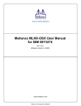
2.1.1.1 Build up Environments
connected through
serial line
Figure 2-1 configuration environment of SICOM6496 out-of-band management
As shown in Figure 2-1, use serial line to connect PC serial port (RS-232) with the switch.
Device instructions:
Device Name
Description
Serial line
One end of serial line connects with PC RS232 serial port, the
other end links with CONSOLE interface of SICOM6496
PC
SICOM6496
It has good Keyboard and RS232 serial port, and installs
terminal
emulation
program,
such
as
Windows
9x/NT/2000/XP’s hyper terminal, etc
It has a good CONSOLE interface
2.1.1.2 Enter Hyper Terminal
After successful connection, open Windows system hyper terminal. Here is an example of opening
Windows XP hyper terminal:
1. Click hyper terminal
14
Figure 2-2 Open hyper terminal (1)
2. Type the name of hyper terminal, such as SICOM6496
Figure 2-3: open hyper terminal (2)
3. Select RS232 serial port (COM port) in “used when connection”, such as choosing COM1 when
use serial port 1. Click “apply”
15
Figure 2-4: open hyper terminal (3)
On the COM1 Properties window, there are the following: set baud rate to 9600 bit/s , 8 data bit, no
parity, 1 stop bit, no flow control; or directly click the button of “restore defaults”, then click “Apply”
Figure 2-5: Open hyper terminal (4)
4. The configuration interface of hyper terminal is presented:
16
Figure 2-6: open hyper terminal (5)
2.1.1.3 Enter Switch CLI interface
Trun switch power on. The following prompt will be presented in hyper terminal configuration
interface to enter CLI configuration mode of SICOM6496.
KYLAND
Copyright (c) 2004 by KYLAND
All rights reserved.
Testing RAM...
67,108,864 RAM OK.
Loading system...
Starting system...
KYLAND Series Switch Operating System, Version RW-0.0.38
Copyright (C) 2001-2004 KYLAND
http://www.kyland.com.cn
SICOM6496 Switch
KYLAND>
17
Then, user can type related commands to do management. The command details are introduced in
following chapters.
2.1.2 In-band Management
In-band management is to log on switch through Telnet program, or to configure and manage
switch through KYLAND’s network management software Kyvision. In-band management make
some devices connected with switch has switch management functions. When in-band management
does not work caused by changes in switch configuration, it is able to use out-of-band management
to operate configuration and management.
2.1.2.1 Switch Management through Telnet
The requirements for Telnet management:
1. Switch has been configured IP address.
2. The IP addresses of PC serving as Telnet user and the IP address of switch VLAN interface
connected with PC should be in a same segment.
3. If not satisfying item 2, Telnet user can use router or other devices to reach a switch IP address.
SICOM6496 is a layer 3 switch which can set multi IP addresses. For more details, please refer to
chapter 4.3. Here is an example: only VLAN1 exist in the system when switch leaves the factory
The steps of Telnet user Telnet to switch VLAN1 interface
connected with
network line
Figure 2-7: switch management through Telnet
Step 1: Configure switch IP address
Firstly, configure PC IP address which must be in a same segment with the IP address of switch
VLAN1 interface connected with PC, such as the IP address of switch VLAN1 interface is
10.1.128.251, so the PC IP address can be set to 10.1.128.252. Operate “ping 10.1.128.251”
command in the PC to check whether they can communicate. If not, please find out the reason.
A brief introduction of the commands of configuring SICOM6496 VLAN1 interface IP address. Before
in-band management, configure switch IP address through CONSOLE Interface (out-of-band
management), and the configuration commands are as follows: (all command prompts are “Switch”
in switch configuration unless noted otherwise)
Switch>
Switch>en
18
Switch#config
Switch(Config)#interface vlan 1
Switch(Config-If-Vlan1)#ip address 10.1.128.251 255.255.255.0
Switch(Config-If-Vlan1)#no shut
Step 2: run Telnet user program
Run Windlows Telnet user program and specify the destination address of Telnet.
Figure 2-8: run Windows Telnet user program
Step 3: log on switch
Typing the correct login name and password to log on Telnet configuration interface, otherwise the
access of this Telnet user will be denied. This measure is to protect switches against illegal operation
of unprivilege user. If switches do not set authorized Telnet users, no user can enter switch CLI
configuration interface, so when it is allowed to configure and manage switches through Telnet, use
Telnet-user <user> password {0|7} <password> command in global configuration mode through
Console interface to set Telnet privilege users and password for switch. For example, the privilege
user name is test, and the password is plain test; the configuration mode is as follows:
Switch>en
Switch#config
Switch(Config)#Telnet-user test password 0 test
Typing correct login name and password in Telnet configuration interface, Telnet user can
successfully enter switch CLI configuration interface. After login through Telnet, the used commands
are the same as those used after login by CONSOLE interface
19
Figure 2-9: Telnet configuration interface
2.1.2.2 Switch Management through Kyvision
The requirements of switch management through Kyvision:
1. Switch has configured IP address.
2. The IP addresses of PC serving as Telnet user and the IP address of switch VLAN interface
connected with PC should be in a same segment.
3. If not satisfying item 2, Telnet user can use router or other devices to reach a switch IP address.
The PC installing Kyvision network management software must be able to connect with switch IP
address through ping command, so when running Kyvision, Kyvision can find SICOM6496 and
perform read and write operation to it. About how to manage switch through Kyvision, please refer
to Kyvision user manual.
2.2 Management Interface
SICOM6496 provides 3 types of management interfaces: CLI (Command Line Interface), web
management interface and Kyvision network management software. We will introduce CLI interface
in detail. About Kyvision, please go through Kyvision user manual.
2.2.1 CLI Interface
User are familiar with CLI interface. Aforementioned out-of-band management and Telnet login both
use CLI interface to configure switch.
CLI interface, provided by Shell program, is composed of series configuration commands. Shell
classifies these commands by their different functions on switch configuration. Different kinds of
commands correspond to different configuration modes. The following article provides a detailed
explanation of switch Shell features.
Configuration mode
20
Configuration grammar
Shortcut key
Help function
A check made on input data
Support incomplete match
2.2.1.1 Configuration Mode Introduction
Figure 2-10 Shell configuration mode of SICOM6496
2.2.1.1.1 General User Configuration Mode
When users enter CLI interface, the first configuration mode they met is General User Configuration
Mode with the prompt of “Switch>”. “>” is always a prompt for general user configuration mode.
When users use exit command in privilege user configuration mode to escape, they will return to
general user configuration mode.
Usera are unable to configure switch in general user configuration mode in which users can only
inquire switch clock and version information.
2.2.1.1.2 Privilege User Configuration Mode
In general user configuration mode, use enable command, input the privilege user password if it has
been set to enter privilege user configuration mode “Switch#”. When users use exit command to exit
from global configuration mode, they will also return to privilege user configuration mode. Moreover,
SICOM6496 provides shortcut “Ctrl+z” to let switch in any configuration mode (except general user
configuration mode) return to privilege user configuration mode.
In privilege user configuration mode, user is able to inquire switch configuration information,
connection state of each port, statistics on received and transmitted data, etc. Besides, after entering
privilege user configuration mode, users may enter global configuration mode to revise all switch
configurations, so privilege user password must be set to avoid illegal use and malicious destroy of
switch configuration from non-privilege user, leading to the loss.
21
2.2.1.1.3 Global Configuration Mode
In privilege user configuration mode, use config comamand to enter global configuration mode
“Switch(Config)#”. When in other configuration modes, such as interface configuration mode, VLAN
configuration mode, users can use exit command to get back to global configuration mode.
In global configuration mode, users can make global configuration to switch, such as configuring MAC
address table, port mirroring, creating VLAN, starting up IGMP Snooping, GVRP, STP, etc. Furthermore,
user is able to configure each port by commands in global configuration mode.
2.2.1.1.3.1 Interface Configuration Mode
In global configuration mode, use command interface to enter interface configuration mode.
SICOM6496 operation system provides 3 types of ports: 1. VLAN interface; 2. Ethernet port; 3.
port-channel, so there are also three types of interface configuration modes.
Port type
Type of access
prompt
VLAN
interface
In global
configuration mode,
type Command:
interface vlan
<Vlan-id>。
Switch(Config-If-
Ethernet port
In global
configuration mode,
type Command:
interface ethernet
<interface-list>。
Switch(Configethernetxx)#
port-channel
In global
configuration mode,
type command
interface
port-channel
<port-channel-numb
er>。
Switch(Config-ifport-channelx)#
Vlanx)#
Functions
Configure
switch IP, etc
Configure
Ethernet
ports’duplex
mode,
speed,etc
Configure
port-channel’s
dulexmode,
speed,etc.
Type of exit
Use command
exit to return to
global
configuration
mode
Use command
exit to return to
global
configuration
mode
Use command
exit to return to
global
configuration
mode
2.2.1.1.3.2 VLAN Configuration Mode
In global configuration mode, use command vlan <vlan-id> to enter VLAN configuration mode. In
VLAN configuration mode, user can configure the members of ports in the VLAN. Operate exit
command to return to global configuration mode.
2.2.1.1.3.3 DHCP Address Pool Configuration Mode
In global configuration mode, use ip dhcp pool <name> command to enter DHCP address pool
configuration mode “Switch(Config-<name>-dhcp)#”. In this mode, user can configure the
properties of DHCP address pool. Operate “exit” command to return to global configuration mode.
22
2.2.1.1.3.4 Routing Configuration Mode
Routing
Protocol
Access
Method
Prompt
Functions
RIP
Routing
Protocol
In global
configuration
mode, input
command
router rip
Switch(Config-Router-Rip)#
Configure
RIP protocol
parameters
OSPF
Routing
Protocol
In global
configuration
mode, input
command
router ospf
Switch(Config-Router-Ospf)#
Configure
OSPF
protocol
parameters
2.2.1.1.3.5 Access List Configuration Mode
Type of access list
Access method
Prompt
Exit Method
Operate
command
“exit” to
return to
global
configuration
mode
Operate
command
“exit” to
return to
global
configuration
mode
Functions
Standard IP Access
List
configuration mode
In global
configuration
mode, enter
command ip
access-list
standard
Switch(Config-Std-Nac
l-a)#
Configure
standard
access list
parameters
Extended IP Access
List configuration
mode
In global
configuration
mode, enter
command ip
access-list
extended
Switch(Config-Ext-Nac
l-b)#
Configure
extended
access list
parameters
2.2.1.2 Grammar Configuration
Exit
Method
Operate
command
“exit” to
return to
global
configurati
on mode
Operate
command
“exit” to
return to
global
configurati
on mode
SICOM6496 provides various configuration commands for users. Although the types of these
configuration commands are different, they all follow SICOM6496 configuration command grammars.
The general command formats offered by switch are as follows:
cmdtxt <va riable> { enum1 | … | enumN } [option]
Grammar explanation: cmdtxt means key word of command; <va riable> means that the parameter
23
is a variable; {enum1 | … | enumN } means that the parameter must be chosen from the group of
enum1~enumN; in [option], “[ ]” means that this parameter is optional. Symbols “< >”, “{ }”, “[ ]” are
used together in lots of commands, such as [<variable>],{enum1 <variable>| enum2},[option1
[option2]], etc
Next is specific ananalysis on some kinds of configuration command grammars:
show version: no parameter; it only has keywords; just type the command directly
vlan<vlan-id>: after typing key words, corresponding parameters are also needed
duplex {auto|full|half}: for this kind of command, user may input “duplex half” or “duplex full”
or “duplex auto”
snmp-server community {ro|rw} <string>: with following situations
snmp-server community ro <string>
snmp-server community rw <string>
2.2.1.3 Support Shortcuts
For user easy configuration, SICOM6496 provides shortcuts, such arrow keys (up, down, left, right),
Backspace, etc. If hyper terminal can’t identify up and down keys, user can use ctrl+p and ctrl+n to
replace them.
.
Key
BackSpace
“↑”
“↓”
“←”
“→”
Ctr+p
Ctr+n
Ctr+b
Ctr+f
Ctr+z
Ctr+c
Tab
Function
Delete the preceding character and the cursor move forward
Display previous commands with max 10 commands
display next command. When cursor is in one of the previous
commands, use “ ↓”to m ove cursor to itsnext command
move cursor left one character
move cursor right one charatcer
it is equivalent to “ ↑”
it is equivalent to “ ↓”
it is equivalent to “ ←”
it is equivalent to “ →”
in other configuration modes (except general user configuration
mode), use this to directly return to privilege user configuration
mode
interrupt the process of switch ping command or other running
commands
when the input string can show command and keyword without
collision, press Tab key to complete the command or keyword.
2.2.1.4 Help Function
SICOM6496 offers two methods for users to get help information: one is “help” command, and the
other is “?”.
Help
“?”
Help
Usage and functions
In any command mode, enter “help” command to get a brief introduction
of help system
1. In any command mode, input “?” to obtain all commands in this mode
24
and their brief introductions
2. Type ”Space+?” after command keywords. If it is a parameter in the
position of “?”, system will output the descriptions of parameter type,
range, etc. if it is a key word in this pisition, it will list a set of this
keyword and their brief introductions. If it is “<cr>”, it means that this
command is completed, so just type “Enter”.
3. Directly input “?” after a string, it will list all commands with the same
beginning of this string.
2.2.1.5 A Check Made on Input Data
2.2.1.5.1 the returned information if succeed
All commands input through keyboard will accept Shell grammar checking. If user correctly enter
the command and it is operated successfully, no information is presented.
2.2.1.5.2 the returned information if fail
Error information
Unrecognized
parameter!
command
Ambiguous command
or
illegal
Invalid command or parameter
This command is not exist in current
mode
Please configurate precursor command
"*" at frist !
syntax error : missing '"' before the end
of command line!
2.2.1.6 Support Incomplete Match
Reason
The command does not exist or something
wrong in parameter’s range, type and format
There are at least two different explanations on
your input
Command analysis is successful, but there is no
effective parameter record
The command can be analyzed, but it can’t be
configured in current mode
The current input can be correctly analyzed,
but its preceding command has not been
configured.
Quotation marks are used in the command, but
one of marks is missing
SICOM6496 Shell supports imcompletely matched searching commands and key words. When input
commands and keywords without collision, Shell will correctly analyze them. For example:
1. For privilege users, configuring “show interface ethernet 1/1” command, they just need to input
“sh in e 1/1”
2. For privilege users, configuring “show running-config” command, if they only input “sh r”, system
will inform “> Ambigous command!” because Shell couldn’t ensure that “show r” command is
“show rom” or “show running-config”, so users must input “sh ru” to get correct analaysis.
2.2.2
WEB Interface
SICOM6496 provides HTTP web management function. User can configure switch and detect switch
working status through WEB interface.
25
Perform following operations to achieve switch management through WEB interface.
1. Configure valid IP address, mask, default gateway for switch as chapter 5.3
2. Configure management user and user password
3. Connect switch through WEB browser, input user name, password, then you can manage the
switch through WEB interface
2.2.2.1 WEB Command Introduction
2.2.2.1.1 ip http-server
Command: ip http-server
no ip http-server
Function: enable switch WEB management function; no command is to disable switch WEB
management function
Default: WEB management is enabled.
Command mode: global configuration mode
User guide: this command can only be used in CONSOLE. Administrator can use this command to
permit or deny login to switch though Web browser
Example: disable switch WEB function
SWITCH(Config)#no ip http-server
2.2.2.1.2 ip address
Command: ip address <ip-address> <mask> [secondary]
no ip address [<ip-address> <mask>] [secondary]
Function: set the IP address and mask of switch designated VLAN interface; no command is to delete
this IP address configuration.
Parameter: <ip-address> is a IP address with dot-decimal format; <mask> is a subnet mask with
dot-decimal format; [secondary] means that the IP address is a secondary IP address.
Default: switch doesn’t have IP address when leaving factory.
Command mode: VLAN interface configuration mode
User guide: If user wants to configureIP address for a switch, please create a VLAN interface at first.
Example: set IP address of VLAN1 interface to 192.168.0.2.
SWITCH(Config)#interface vlan 1
SWITCH(Config-If-Vlan1)#ip address 192.168.0.2 255.255.255.0
SWITCH(Config-If-Vlan1)#exit
SWITCH(Config)#
Relative Command: ip bootp-client enable, ip dhcp-client enable
2.2.2.1.3 web-user
Command: web-user <username> password {0|7} <password>
no web-user <username>
Function: set the user name and password for user login through WEB browser; no command is to
delete this user
Parameter: <username> is the user name for login through WEB browser with max 16 characters;
<password> is a login password with max 8 characters; 0|7respectively indicate an unencrypted
26
passwrrd and a encrypted password.
Command mode: global configuration mode
Default: there are not username and password for login through Web browser
User guide: use this command to set authorized WEB user. If don’t set authorized WEB user, no user
can configure switch through WEB browser.
Example: set a user with the name “admin” and password “123”
SWITCH(Config)#web-user admin password 0 123
2.2.2.2 WEB Homepage
After entering user name, password and they pass authentication, you will see below WEB
management homepage. Click links in main menu to view and configure management sublinks.
Figure 2-11 WEB management homepage
27
Chapter 3 Switch Basic Configuration
3.1 Basic Configuration Commands
The basic configuration of switch contains the commands to access and exit from privilege user mode,
to access and exit from interface configuration mode, to set and display switch clock, to display switch
system version information, etc.
3.1.1 Clock set
Command: clock set <HH:MM:SS> <YYYY.MM.DD>
Function: set system date and time
Parameter: <HH:MM:SS > is current time. HH is in the range of 0~23; MM and SS are in the range
of 0~59. < YYYY.MM.DD > is current date, including year, month and day. YYYY is in the range of
1970~2100; MM is in the range of 1~12; DD is in the range of 1~31.
Command mode: privilege user configuration mode
Default: system date and time is Jan. 1, 2001, 0: 0: 0
User guide: switch can’t keep measuring time when power off, so current date and time must be set
at first when switch will be used in an environment which has strict requirements on accurate time.
Example: setting the date and time of switch to Aug. 1, 2002, 23:0:0
SWITCH#clock set 23:0:0 2002.8.1
Related Command: show clock
3.1.2 config
Command: config [terminal]
Function: from privilege user configuration mode to global configuration mode
Parameter: [terminal] means making terminal configuration
Command mode: privilege user configuration mode
Example: SWITCH#config
3.1.3 enable
Command: enable
Function: use enable command to enter privilege user configuration mode from general user
configuration mode
Command mode: general user configuration mode
User guide: In order to avoid non-privilege user’s illegal access, user security authentication is
required when entering privilege user configuration mode from general user configuration mode.
The authentication is that users need to type correct privilege user password. After that, users enter
privilege user configuration mode. If continuously input incorrect password 3 times, general user
configuration mode remains unchanged. Use command “enable password” in global configuration
mode to set privilege user password.
Example:
SWITCH>enable
password: ***** (admin)
SWITCH#
Related Command: enable password
3.1.4
enable password
Command: enable password
Function: change the password of accessing privilege user configuration mode from general user
28
configuration
mode.
Type
this
command
and
press
“Enter”
directly,
then
<Current
password> ,<New password> parameters are displayed, which need to be configured
Parameter:
<Current password> is the original password with max 16 characters; <New
password> is a new password with max 16 characters; <Confirm new password> is to confirm the
new password which should be the exact same as new password, otherwise, password need to be
reconfigured.
Command mode: global configuration mode
Default: privilege user password is empty. When users configure the password for the first time, just
press “Enter” when system give you a message to enter origimal password.
User guide: privilege user password configuration is to avoid non-privilege user’s illegal access. We
recommend that setting privilege user password when network administrator make first
configuration for switch. Moreover, if administrator will keep away from the terminal screen for a
long time, please operate “exit” command to exit from privilege user configuration mode.
Example: set privilege user password to admin
SWITCH(Config)#enable password
Current password:
New password:*****
(in the first configuration, no password, press “Enter” directly)
(set new password to admin)
Confirm new password:***** (confirm new password admin)
SWITCH(Config)#
Related Command: enable
3.1.5 exec timeout
Command: exec timeout <minutes >
Function: set the timeout to exit form privilege user configuration mode
Parameter: < minute > is a time value with the unit of minute and in the range of 0~300.
Command mode: global configuration mode
Default: 5 minutes
User guide: in order to ensure the security of switch and avoid illegal user’s malicious operation,
system start to measure time when privilege user finish their configuration, and when the time reach
the setting timeout, system will automatically exit from privilege user configuration mode. If user
wants to enter privilege user configuration mode again, please re-enter privilege user password. If
exec timeout is set to 0, it means that system won’t exit from privilege user configuration mode,
Example: set the timeout of switch exiting from privilege user configuration mode to 6 minutes
SWITCH(Config)#exec timeout 6
3.1.6
exit
Command: exit
Function: exit from current mode and return to previous mode, such as use this command to exit
from global configuration mode and return to privilege user configuration mode, use this command to
exit from privilege user configuration mode and return to general user configuration mode, etc.
Command mode: all configuration modes
29
Example:
SWITCH#exit
SWITCH>
3.1.7
help
Command: help
Function: output a brief introduction of command help system
Command mode: all configuration modes
User guide: switch provides online help at any moment and place. “help” command is to indicate the
information about whole help system including full help, partial help. User can type “?” to obtain
online help at any moment and place.
Example;
SWITCH>help
enable
exit
help
show
-- Enable Privileged mode
-- Exit Telnet session
-- help
-- Show running system information
3.1.8 ip host
Command: ip host <hostname> <ip_addr>
no ip host <hostname>
Function: set host-to-IP address mapping relationship; no command is to delete this mapping relation.
Parameter: <hostname> is a hostname with max 15 characters. <ip_addr> is the corresponding IP
address of hostname with dot-decimal format.
Command mode: global configuration mode
User guide: setting a corresponding relation of host and IP address, which can be used in commands,
such as “ping <host>”
Example: set IP address of a host with the name of beijing to 200.121.1.1
SWITCH(Config)#ip host beijing 200.121.1.1
Related Command: Telnet, ping, traceroute
3.1.9 hostname
Command: hostname <hostname>
Function: set the prompt in switch CLI interface
Parameter: <hostname> is a string of prompt with max 30 characters
Command mode: global configuration mode
Default: the prompt is “KYLAND”.
User guide: use this command to set switch CLI prompt according to actual conditions.
Example: setting prompt to Test
SWITCH(Config)#hostname Test
Test(Config)#
3.1.10 reload
30
Command: reload
Function: hot-start switch
Command mode: privilege user configuration mode
User guide: user can use this command to restart when power doesn’t cut off
3.1.11 set default
Command: set default
Function: restore switch factory defaults
Command mode: privilege user configuration mode
User guide: restore switch factory settings. all configurations user made to switch are deleted and
after restarting the switch, the prompt appeared is the same as the one when switch was powered
on for the first time.
Note: after configuring this command, user must operate write command. After saving configuration,
restart the switch, then it restore to factory defaults.
Example:
SWITCH#set default
Are you sure? [Y/N] = y
SWITCH#write
SWITCH#reload
3.1.12 setup
Command: setup
Function: enter switch Setup configuration mode
Command mode: privilege user configuration mode
User guide: SICOM6496 provides Setup configuration mode. User can configure IP address, etc in
Setup configuration mode.
3.1.13 language
Command: language {chinese|english}
Function: set the language of help information
Parameter: Chinese and English
Command mode: privilege user configuration mode
Default: English
User guide: SICOM6496 displays help information in 2 languages. User can choose according to their
own requirements. Help information is in English after system is restarted,
3.1.14 write
Command: write
Function: save all running configuration parameters to Flash Memory
Command mode: privilege user configuration mode
User guide: when finish a set of configurations and they accomplish their intended results, save the
current configuration to Flash, so that system can automatically restore all factory settings when
switch is powered off or shut down carelessly. This command is equivalent to copy running-config
31
startup-config command.
Related commands: copy running-config startup-config
3.2 Maintenance and Debugging Commands
When users configure switch, they want to check if all configuration are right and if switch run well,
or they need fault diagnosis when network meets problems, SICOM6496 provides various debugging
commands, such as ping, Telnet, show, debug, etc. to help user check system configuration, operation
status, and discover the cause of the trouble.
3.2.1 ping
Command: ping
[<ip-addr>]
Function: switches send ICMP request packets to remote devices to check if aisles between switch
and remote devices are unobstructed.
Parameter: <ip-addr> is the IP address of the Ping destination host with dot-decimal format
Default: send 5 ICMP request packets with the size of 56 byrtes and the timeout of 2 seconds
Command mode: privilege user configuration mode
User guide: input “ping” command, press “Enter” directly, and system provides a interactive
configuration mode for users who can define ping parameters by themselves.
Example:
Example 1: use the defaults of ping program
SWITCH#ping 10.1.128.160
Type ^c to abort.
Sending 5 56-byte ICMP Echos to 10.1.128.160, timeout is 2 seconds.
...!!
Success rate is 40 percent (2/5), round-trip min/avg/max = 0/0/0 ms
In above example, switch sends ping command to a device with IP address of 10.1.128.160. If the
switch doesn’t receive corresponding ICMP response packets of the first three ICMP request packets
in the default timeout of 2 seconds, it means that ping fails, but the last two packet get responses with
the successful rate of 40%. Switch uses “.” to indicate ping failure and link disconnection; use “!” to
say ping success and link connection.
Example 2: use the methods provided by ping program to modify ping parameters
SWITCH#ping
protocol [IP]:
Target IP address:10.1.128.160
Repeat count [5]:100
Datagram size in byte [56]:1000
Timeout in milli-seconds [2000]:500
Extended commands [n]:n
Information
Explanation
32
protocol [IP]:
Select Ping for IP protocol
Datagram size in byte [56]
The size of ICMP packet with the default of
56byte
Target IP address:
Repeat count [5]
Timeout in milli-seconds [2000]:
Extended commands [n]:
3.2.2
The IP address of the destination device
The number of the sending packets; the
default is 5
The timeout with the unit of millisecond
and the default is 2 seconds
Telnet
3.2.2.1 Telnet Introduction
Telnet remote login is a simple remote terminal protocol. By Telnet, user can log on a remote host
with IP address or host name through TCP connection. Telnet can send user’s keystrokes to remote
host and meanwhile return the output of remote host to user’s screen through TCP connection. This
service is transparent because user feel that keyboard and screen are directly connected with
remote host.
Telnet adopts user-server mode. The local system is Telnet user and remote host is Telnet server.
SICOM6496 can serve as Telnet server and Telnet user.
When SICOM6496 works as Telnet server, user can Telnet SICOM6496 through Telnet user software
of Windows or other operation system. As we introduced in-band management in previous chapter,
SICOM6496, working as Telnet server, can establish TCP connection with max 5 Telnet users at the
same time.
When SICOM6496 serves as a Telnet user, use Telnet command in switch privilege user configuration
mode to log on other remote host. SCIOM6496, serving as Telnet user, can establish TCP connection
with only one remote host. If switch wants to connect with other remote host, pleae disconnect
current TCP connection at first.
3.2.2.2 Task Sequence of Telnet
1. Telnet server configuration
2. Switch Telnet remote host
1. Telnet server configuration
Command
Global configuration mode
Telnet-server enable
no Telnet-server enable
Telnet-user <user-name> password {0|7}
<password>
no Telnet-user <user-name>
Telnet-server securityip <ip-addr>
Explanation
Enable Telnet server function; no
command is to disable Telnet server
function
Configure the user name and password
to Telnet switch; no command is to
delete authorized Telnet user
Configure secure IP address for Telnet
33
no Telnet-server securityip <ip-addr>
Privilege mode
monitor
no monitor
2. Switch Telnet remote host
Privilege mode
switch; no command is to delete
authorized Telnet secure addresses
Let switch Telnet user display debugging
information; no command is to close this
function.
Command
Telnet [<ip-addr>] [<port>]
Explanation
Use switch Telnet users to log on
remote host
3.2.2.3 Telenet Command Introduction
3.2.2.3.1 monitor
Command: monitor
no monitor
Function: enable Telnet user to show debugging information and close the function of showing
debugging information at Console interface; no command is to disable Telnet user to show debugging
information and resume the function of showing debugging information at Console interface.
Command mode: privilege user configuration mode
User guide: Generally when Telnet user access switch, if open Debug information, it won’t be
displayed in Telnet interface, but displayed in hyper terminal connected with Console interface. Use
this command to make debugging information displayed in designated Telnet terminal interface, but
not in Console or other Telnet terminal interface.
Example: enable Telnet user to show debugging information
SWITCH#monitor
Related Command: Telnet-user
3.2.2.3.2 Telnet
Command: Telnet [<ip-addr>] [<port>]
Function: log on a remote host with IP address of <ip-addr> in the form of Telnet
Parameter: <ip-addr> is the IP address of remote host with dot-decimal format. <port> is the port
number in the range of 0~65535.
Command mode: privilege user configuration mode
User guide: when switch works as Telnet user, user can use this command to login to remote host to
make configuration. When switch serves as Telnet user, it can establish TCP connection with only one
remote host. If it wants to connect with other remote host, please cut off the current TCP connection
at first. Shortcut “CTRL+ |” canbe used to achieve disconnection.
Directly enter keyword Telnet without other parameter, then user will enter Telnet configuration
mode.
34
Example: switch Telnet the remote router KYLNAD with IP address of 20.1.1.1.
SWITCH#Telnet 20.1.1.1 23
Trying 20.1.1.1...
Service port is 23
Connected to 20.1.1.1
login:123
password:***
KYLAND>
3.2.2.3.3 Telnet-server enable
Command: Telnet-server enable
no Telnet-server enable
Function: enable Telnet server function of switch; no command is to disable Telnet server function of
switch
Default:enable Telnet server function
Command mode: global configuration mode
User guide: this command can be used only at CONSOLE. Administrator use this command to permit
or deny Telnet users to log on switch.
Example: disable switch Telnet server function
SWITCH(Config)#no Telnet-server enable
3.2.2.3.4 Telnet server security ip
Command: Telnet-server securityip <ip-addr>
no Telnet-server securityip <ip-addr>
Function: when switch works as Telnet server, use this command to configure a secure ip address of
Telnet user which is allowed to login; no command is to delete the secure IP address of designated
Telnet user
Parameter: <ip-addr> is a secure IP address with dot-decimal format which is permitted to access
switch
Default: no secure IP address
Command mode: global configuration mode
User guide: Before setting secure IP addresses, there is a limit to the IP address of switch Telnet user.
After the secure IP address configuration, only the host with a secure ip address can Telnet switch to
make configuration. Switch allows to configure multiple secure IP addresses.
Example: setting 192.168.1.21 to a secure IP address
SWITCH(Config)#Telnet-server securityip 192.168.1.21
3.2.2.3.5 Telnet –user
Command: Telnet-user <username> password {0|7} <password>
no Telnet-user <username>
Function: set the user name and password of Telnet user; no command is to delete this Telnet user.
Parameter: <username> is the name of a Telnet user with max 16 characters; <password> is the
35
password with max 8 characters.; 0|7 respectively indicated a unencrypted password and a
encrypted password.
Command mode: global configuration mode
Default: no setting username and password for Telnet user
User guide: this command is used when switch serves as Telnet server. use this command to set
authorized Telnet user. If doesn’t set authorized Telnet user, no Telnet user can configure switch
through Telnet. When switch works as Telnet server, it can establish TCP connection with max 5
Telnet users at the same time.
Example: set a Telnet user with the name of Antony and password of switch
SWITCH(Config)#Telnet-user Antony password 0 switch
3.2.3
traceoute
Command: traceroute {<ip-addr> | host <hostname> }[hops <hops>] [timeout <timeout> ]
Function: this command is userd to test the number of gateways which the data packages has passed
through from the source device to the destination device and check if the network is unobstructed
and locate network failures.
Parameter: <ip-addr> is the IP address of destination host with dot-decimal format. <hostname> is
the name of remote host. <hops> means the max number of gateways which Traceroute has passed
through. <timeout> is a timeout of packets with the unit of millisecond and in the range of
100~10000.
Default: the max number of gateways is 16 with timeout of 2000ms
Command mode: privilege user configuration mode
User guide: Traceroute is generally used to locate the faults when aisles to destination network are
not unobstructed.
Related Command: ip host
3.2.4
show
show command is to show switch system information, port information, protocol operation status,
etc.. This chapter introduces the show command to show system information. Other show commands
will be introduced in other chapters.
3.2.4.1 show colock
Command: show clock
Function: show system current clock
Command mode: privilege user configuration mode
User guide: user can check system date and time by this command. If system time is wrong, user can
adjust it in time.
Example:
SWITCH#show clock
Current time is TUE AUG 22 11:00:01 2002
Related Command: clock set
36
3.2.4.2 show debugging
Command: show debugging
Function: show the state of debugging switch
User guide: if user want to check which debugging switches are ON, use can operate show
debugging command
Command mode: privilege user configuration mode
Example: check which debugging switches are ON at present
SWITCH#show debugging
STP:
Stp input packet debugging is on
Stp output packet debugging is on
Stp basic debugging is on
SWITCH#
Related Command: debug
3.2.4.3 show flash
Command: show flash
Function: show the files which are saved in flash and their size
Command mode: privilege user configuration mode
Example: check the files in flash and their size
SWITCH#show flash
boot.rom
boot.conf
nos.img
startup-config
3.2.4.4 show history
329,828 1900-01-01 00:00:00 --SH
94 1900-01-01 00:00:00 --SH
2,449,496 1980-01-01 00:01:06 ---2,064 1980-01-01 00:30:12 ----
Command: show history
Function: show the history commands recently entered
Command mode: privilege user configuration mode
User guide: system can save max 10 recently entered commands. User can use up and down cursors
or their equivalent shortcuts (ctrl+p and ctrl+n) to access history commands.
Example:
SWITCH#show history
enable
config
interface ethernet 1/3
enable
show flash
show ftp
3.2.4.5 show memory
Command: show memory
Function: show the contents in designated memory area
37
Command mode: privilege user configuration mode
User guide: this command is for switch debugging. Command is in a interactive way to prompt user
to input the memory address and output words of displayed information which include 3 parts:
address, hexadecimal information and characters.
Example:
SWITCH#show memory
start address : 0x2100
number of words[64]:
002100:
002110:
002120:
002130:
002140:
002150:
002160:
002170:
0000 0000 0000 0000
0000 0000 0000 0000
0000 0000 0000 0000
0000 0000 0000 0000
0000 0000 0000 0000
0000 0000 0000 0000
0000 0000 0000 0000
0000 0000 0000 0000
3.2.4.6 show running-config
0000 0000 0000 0000
0000 0000 0000 0000
0000 0000 0000 0000
0000 0000 0000 0000
0000 0000 0000 0000
0000 0000 0000 0000
0000 0000 0000 0000
0000 0000 0000 0000
*................*
*................*
*................*
*................*
*................*
*................*
*................*
*................*
Command: show running-config
Function: showing the efficient switch parameter configuration in current operating status
Default: for the configuration parameters which are taking effect, if they are the same as the default
parameters, they won’t be displayed.
Command mode: privilege user configuration mode
User guide: when finishing a set of configuration, user need to verify if configurations are correct, by
operating show running-config command to check currently efficient parameters.
Example:
SWITCH#show running-config
3.2.4.7 show startup-config
Command: show startup-config
Function: show switch parameter configurations which are written in Flash Memory in current
operation state. These configurations generally are the configuration files for switch startup the next
time.
Default: If the configuration parameters read from Flash are the same as default parameters, they are
not displayed.
Command mode: privilege user configuration mode
User guide: the difference between show running-config and show startup-config is that when
user finish a set of configurations, users can see the increase of configuration through show
running-config, but they can’t see any configuration through show startup-config. But if user use
write command to save the efficient configurations to Flash Memory, the displayed results are the
same through show running-config and show startup-config
38
3.2.4.8 show switchport interface
Command: show switchport interface [ethernet <interface-list>]
Function: show switch ports’ VLAN port mode, VLAN number and Trunk port information
Parameter: <interface-list> is port number or port list.
Command mode: privilege user configuration mode
Example: show VLAN information of port ethernet 1/1
SWITCH#show switchport interface ethernet 1/1
Ethernet1/1
Type :Universal
Mac addr num :-1
Mode :Access
Port VID :1
Trunk allowed Vlan :ALL
Ethernet1/1
Type
Contents
Mac addr num
Mode :Access
Port VID :1
Trunk allowed Vlan :ALL
3.2.4.9 show tcp
Description
Corresponding Ethernet port number
Current port type
The number of MAC addresses which current
port can learn
VLAN mode of current port
VLAN number of current port
ALL VLANs whichTrunk allow
Command: show tcp
Function: show the current sate of TCP connection established with switch
Command mode: privilege user configuration mode
Example:
Switch#show tcp
LocalAddress
LocalPort ForeignAddress
0.0.0.0
23 0.0.0.0
0
0.0.0.0
80 0.0.0.0
0
content
ForeignPort
LISTEN
LISTEN
State
description
LocalAddress
Local address in tcp connection
ForeignPort
The port number of the other end in tcp connection
LocalPort
ForeignAddress
State
3.2.4.10 show udp
Local port number in tcp connection
The address of the other end in tcp connection
The current state of tcp connection
Command: show udp
Function: show the current state of UDP connection established with switch
39
Command mode: privilege user configuration mode
Example:
SWITCH#show udp
LocalAddress
LocalPort ForeignAddress
0.0.0.0
161
0.0.0.0
0.0.0.0
123
0.0.0.0
0.0.0.0
1985
0.0.0.0
LocalAddress
LocalPort
contents
ForeignAddress
ForeignPort
State
ForeignPort
0
0
0
State
CLOSED
CLOSED
CLOSED
description
Local address in UDP connection
Local port number in UDP connection
The address of the other end in UDP
connection
The port number of the other end in UDP
connection
The current state of UDP connection
3.2.4.11 show Telnet login
Command: show Telnet login
Function: show Telnet user information in switch established Telnet connection
User guide: this command is used to check the information of remote user which login to system
Example:
SWITCH#show telnet login
Antony
SWITCH#
3.2.4.12 show Telnet user
Command: show Telnet user
Function: show the information of Telnet user which has been authorized to visit switch through
Telnet
User guide: this command is used to check the information of all authorized Telnet users
Example:
SWITCH#show telnet user
Antony
Related Command: Telnet-user password
3.2.4.13 show version
Command: show version
Function: show the information of switch version
Command mode: privilege user configuration mode
User guide: use this command to check switch version information, including hardware version and
software version information
Example:
SICOM6496 Device, Sep 8 2004 08:59:51
40
HardWare version is 2.0, SoftWare version is RW-1.2.6.0, BootRom version is 1.2.7
Copyright (C) 2001-2002 by KYLAND.
All rights reserved.
3.2.5
Debug
Each protocol which switch supports has corresponding debug command. User can use debug
command to diagnose network failures. In later chapters, debug commands will be introduced one by
one in their corresponding parotocol.
3.3 Switch IP address Configuration
All SICOM6496 Ethernet ports are default as layer 2 (Data Link Layer) ports, performing layer 2
forwarding. VLAN interface represents the layer 3 interface function of a VLAN, and it can configure
IP address which is also switch IP address. All configuration commands related to VLAN interface can
be set in VLAN interface mode.
SICOM6496 provides 3 methods of IP address configuration.
Manual configuration
Bootp
DHCP
Manual configuration is that user specifies a IP address for switch
BootP/DHCP is that switch serves as BootP/DHCP client and send BootPRequest broadcast packets
to BootP/DHCP server to apply an address. When BootP/DHCP server get the requests, it will
distribute address to switch. Besides, SICOM6496 also supports DHCP server function which can
dynamicly distribute network parameters to DHCP client, suh as IP address, gateway address and
DNS server address, etc
3.3.1 Task sequence of switch IP address configuration
1. manual configuration
2. BootP
3. DHCP
1. manual configuration
Command
ip
address
<ip_address>
[secondary]
no ip address <ip_address>
[secondary]
2. BootP
command
ip bootp-client enable
no ip bootp-client enable
3. DHCP
<mask>
<mask>
Expalanation
Configure the IP address of switch VLAN
interface; no command is to delete the IP
address of switch VLAN interface
explanation
Enable switch BootP Client. Obtain IP
address and gateway address through BootP
negotiation; no command is to disable
BootP Client function
41
command
ip dhcp-client enable
no ip dhcp-client enable
3.3.2
explanation
Enable switch DHCP Client. Obtain IP
address and gateway address through DHCP
negotiation; no command is to disable
DHCP Client function
Switch IP Address Configuration Commands
3.3.2.1 ip address
Command: ip address <ip-address> <mask> [secondary]
no ip address [<ip-address> <mask>] [secondary]
Function: set IP address and mask of switch designated VLAN interface; no command is to delete the
IP address configuration
Parameter: <ip-address> is the IP address with dot-decimal format. <mask> is the subnet mask
with dot-decimal format. [secondary] means the IP address is a secondary IP address.
Default: switch doesn’t have IP address
Command mode: VLAN interface configuration mode
User guide: if user wants to configure switch IP address, please create a VLAN interface at first.
Example: set the IP address of VLAN interface to 10.1.128.1/24.
SWITCH(Config)#interface vlan 1
SWITCH(Config-If-Vlan1)#ip address 10.1.128.1 255.255.255.0
SWITCH(Config-If-Vlan1)#exit
SWITCH(Config)#
Related Command: ip bootp-client enable, ip dhcp-client enable
3.3.2.2 ip bootp-client enable
Command: ip bootp-client enable
no ip bootp-client enable
Function: set switch to be BootP Client. Obtain IP address and gateway address through BootP
negotiation; no command is to disable BootP Client function and release IP address and gateway
address obtained by BootP
Default: disable BootP Client function
Command mode: VLAN interface configuration mode
User guide: obtaining IP address through BootP and through manual configuration or DHCP are
mutually exclusive. Opening two IP address obtaining methods at the same time are not allowed.
Example: obtain IP address through BootP
SWITCH(Config)#interface vlan 1
SWITCH(Config-If-Vlan1)#ip bootp-client enable
SWITCH(Config-If-Vlan1)#exit
SWITCH(Config)#
Related Command: ip address, ip dhcp-client enable
3.3.2.3 ip dhcp-client enable
Command: ip dhcp-client enable
no ip dhcp-client enable
42
Function: set switch to be DHCP Client. Obtain IP address and gateway address through DHCP
negotiation; no command is to disable DHCP Client function and release IP address and gateway
address obtained by DHCP
Default: disable DHCP Client function
Command mode: VLAN interface configuration mode
User guide: obtaining IP address through DHCP and through manual configuration or BootP are
mutually exclusive. Opening two IP address obtaining methods at the same time are not allowed.
Example: obtain IP address through DHCP
SWITCH(Config)#interface vlan 1
SWITCH(Config-If-Vlan1)#ip dhcp-client enable
SWITCH(Config-If-Vlan1)#exit
SWITCH(Config)#
Related: ip address, ip bootp-client enable
3.4 SNMP configuration
3.4.1 SNMP introduction
SNMP (Simple Network Management Protocol) is a standard protocol for internet management,
which are widely used in computer network management. SNMP increasingly develop. SNMP
v1[RFC1157] is the first version of SNMP. SNMPv1 is simple and easy to implement, so it receives
wide acceptation. With the development of function and security performance, SNMP developedto
version 2 SNMPv2 which are based on SNMPv1. So we will pay more emphasis on SNMPv1. In this
paper, SNMP denotes SNMPv1 if it isn’t specified,
SNMP protocol provides a direst method of exchanging management information between two points
in a network. SNMP adopts polling as information query method, so it can be well supported by
current computer network.
SNMP protocol adopts management station/ Agent mode, so SNMP contains two parts: NMS (network
Management Station) , it operate SNMP-supported network management software client program
station and it takes core effect; Agent is a server software which operate in the managed network
devices and directly manage the managed objects. NMS use communication method to manage the
managed objects through Agent.
SNMP’s NMS and Agent adopt client/server mode to intercommunicate through standard messages.
NMS send requests; Agent give response. SNMP has 5 types of messages
Get-Request
Get-Response
Get-Next-Request
Set-Request
Trap
3.4.2 MIB introduction
A management information base (MIB) is a virtual database used for managing the entities in a
communications network. The database is hierarchical (tree-structured) and entries are addressed
43
through object identifiers. SICOM6496 can work as SNMP agent, support SNMPv1/v2c, support
basic MIB-II, RMON, common MIB and supports BRIDGE MIB, etc
3.4.3 RMON introduction
The Remote Network MONitoring (RMON) MIB was to support monitoring and protocol analysis of
LANs.
The RMON MIB consists of ten groups. SICOM6496 support the most often used group 1, 2, 3 and 9
Statistics: real-time LAN statistics e.g. utilization, collisions, CRC errors
History: history of selected statistics
Alarm: definitions for RMON SNMP traps to be sent when statistics exceed defined thresholds
Event: send alerts (SNMP traps) for the Alarm group
Token Ring: extensions specific to Token Ring
3.4.4 SNMP Configuration
3.4.4.1 Task Sequence of SNMP configuration
1. enable or disable SNMP Agent server function
2. configure SNMP community string
3. configure secure IP address of SNMP management station
4. configure TRAP
5. enable or disable RMON
1. enable or disable SNMP Agent server function
Command
snmp-server enable
no snmp-server enable
2. Configure SNMP community string
Command
snmp-server community {ro|rw} <string>
no snmp-server community <string>
explanation
enable switch to be SNMP Agent server;
no command is to disable SNMP agent
server function
explanation
Set switch community string; no
command is to delete the community
string configuration
3. Configure secure IP address of SNMP management station
Command
explanation
snmp-server securityip <ip-address>
no snmp-server securityip <ip-address>
4. configure TRAP
command
snmp-server enable traps
Set a secure IP address of switch NMS
which is allowed to access switch; no
command is to delete the configured
secure IP address
explanation
device is allowed to send Trap message;
44
no snmp-server enable traps
snmp-server
host
<host-addr>
<community-string>
no snmp-server host <host-addr>
5. enable or disable RMON
Command
rmon enable
no rmon enable
3.4.4.2 SNMP Configuration Commands
no command is to forbid sending Trap
message
Set the IP address and Trap community
string of NMS which receives SNMP Trap
message; no command is to delete the IP
address of designated NMS which receives
Trap message
explanation
Enable or disable RMON
3.4.4.2.1 rmon
Command: rmon enable
no rmon enable
Function: enable switch RMON function; no command is to disable RMON function
Command mode: global configuration mode
Default: disable RMON
Example:
enable RMON function
Switch(Config)#rmon enable
Disable RMON function
Switch(Config)#no rmon enable
3.4.4.2.2 snmp-server community
Command: snmp-server community {ro|rw} <string>
no snmp-server community <string>
Function: set switch community string; no command is to delete the community string configuration
Command mode: global configuration mode
Parameter: <string> is a community string. ro|rw is to specify the method to access MIB, ro means
read only; rw means read and write.
User guide: switch supports max 4 community strings.
Example:
Add read and write community string “private”
Switch(Config)#snmp-server community rw private
Add read only community string “public”
Switch(Config)#snmp-server community ro public
Change the community string “private” from read and write to read only
Switch(Config)#snmp-server community ro private
Delete community string “private”
Switch(Config)#no snmp-server community private
45
3.4.4.2.3 snmp-server enable
Command: snmp-server enable
no snmp-server enable
Function: enable SNMP agent server functions in switch; no command is to disable SNMP agent
server function
Command mode: global configuration mode
Default: disable SNMP agent server function
User guide: if switch wants to manage configuration through network management software, pleae
use this command to enable switch SNMP agent server function at first.
Example: enable switch SNMP agent server function
Switch(Config)#snmp-server enable
3.4.4.2.4 snmp-server enable traps
Command: snmp-server enable traps
no snmp-server enable traps
Function: allow device to send Trap message; no command is to forbid sending Trap message
Command mode: global configuration mode
Default: forbid sending Trap messages
User guide: when device is allowed to send Trap message, device will send Trap message to
management station which can receive Trap message if device port is DOWN/UP or system is
DOWN/UP.
Example:
Allow sending Trap message
Switch(Config)#snmp-server enable traps
Forbid sending Trap message is forbidden
Switch(Config)#no snmp-server enable trap
3.4.4.2.5 snmp-server host
Command: snmp-server host <host-addr> <community-string>
no snmp-server host <host-addr>
Function: set the IP address and Trap community string of NMS which receives SNMP Trap message;
no command is to delete the IP address of designated NMS which receive Trap message
Command mode: global configuration mode
Parameter:
<host-addr> is the IP address of NMS which receives Trap messages.
<community-string> is the community string used in sending Trap messages.
User guide: this command is to set the community string of sending Trap to the default value of
RMON event community string. If RMON events don’t set community string, use the community string
set by this command when sending RMON Trap. If RMON events have set community string, send
RMON Trap with RMON community string.
Example:
Set a IP address of receiving Trap
46
Switch(Config)#snmp-server host 1.1.1.5 dcstrap
Delete a IP address of receiving trap
Switch(Config)#no snmp-server host 1.1.1.5
3.4.4.2.6 snmp-server securityip
Command: snmp-server securityip <ip-address>
no snmp-server securityip <ip-address>
Function: set a secure IP address of NMS which is allowed to access switch; no command is to delete
secure IP address configuration
Command mode: global configuration mode
Parameter: <ip-address> is a secure IP address of NMS with dot-decimal format
User guide: only when the IP address of NMS accords is the same with the secure IP address set by
this command, SNMP packets sent by NMS will be processed by switch.
Example:
Set the secure IP address of NMS
Switch(Config)#snmp-server securityip 1.1.1.5
Delete the secure IP address
Switch(Config)#no snmp-server securityip 1.1.1.5
3.4.5 SNMP Typical Configuration Example
Figure 3-2: SNMP configuration example
IP address of NMS is 1.1.1.5; IP address of switch (Agent) is 1.1.1.9.
Example 1: network management software of NMS use SNMP protocol to obtain switch data.
The switch configuration is as follows:
Switch(Config)#snmp-server enable
Switch(Config)#snmp-server community rw private
Switch(Config)#snmp-server community ro public
Switch(Config)#snmp-server securityip 1.1.1.5
In this way, NMS can use private as community string to perform read and write access of switch,
and also can use public as community string to make read only access of switch
47
Example 2: NMS receives switch Trap messages (note: NMS might has set authentication to Trap
community string, so we suppose that Trap authentication community string of NMS is dcstrap).
The switch configuration is as follows:
Switch(Config)#snmp-server host 1.1.1.5 dcstrap
Switch(Config)#snmp-server enable traps
3.4.6 SNMP Troubleshooting Help
3.4.6.1 monitoring and debugging command
3.4.6.1.1 show snmp
Command: show snmp
Function: show all SNMP counter informations
Command mode: privilege user configuration mode
Example:
Switch#show snmp
0 SNMP packets input
0 Bad SNMP version errors
0 Unknown community name
0 Illegal operation for community name supplied
0 Encoding errors
0 Number of requested variables
0 Number of altered variables
0 Get-request PDUs
0 Get-next PDUs
0 Set-request PDUs
0 SNMP packets output
0 Too big errors (Max packet size 1500)
0 No such name errors
0 Bad values errors
0 General errors
0 Get-response PDUs
0 SNMP trap PDUs
snmp packets input
content
The total number of input SNMP
packets
bad snmp version errors
unknown community name
illegal operation
supplied
encoding errors
for
explanation
community
number of requested variablest
The number of packets with error
version information
name
The number of packets with error
community name
the number of packets with illegal
operation for community name
the number of SNMP packets with
encoding errors
the number of variables which NMS
48
number of altered variables
get-request PDUs
get-next PDUs
requests
the number of variables which NMS set
the number of packets receiving get
requestes
the number of packets receiving getnext
requestes
set-request PDUs
snmp packets output
too big errors
maximum packet size
no such name errors
bad values errors
general errors
the number of packets receiving set
requestes
the number of output SNMP packets
the number of SNMP packets with
too_big errors
the max size of SNMP packets
the number of packets sending request
to nonexistent MIB
the number of SNMP packets with
bad_values errors
the number of SNMP packets with
general_values errors
response PDUs
number of sending response packets
trap PDUs
number of trap packets
3.4.6.1.2 show snmp status
Command: show snmp status
Function: show SNMP configuration information
Command mode: privilege user configuration mode
Example:
Switch#show snmp status↵
System Name :
System Contact :
System Location :
Trap enable
RMON enable
Community Information:
Trap manager Information:
Security IP Information:
System Name
System Contact
content
System Location
Trap enable
RMON enable
Community Information
Trap manager Information
system name
description
system contact information
system location
enable or disable SNMP Trap function
enable or disable SNMP RMON
the information of community string
the information of Trap host
49
Security IP Information
Security IP information
3.4.6.1.3 debug snmp packet
Command: debug snmp packet
no debug snmp packet
Function: turn on SNMP debugging switch; no command is to turn off debugging switch
Command mode: privilege user configuration
User guide: when user meets problems in using SNMP, user can turn on SNMP debugging switch to
discover the cause
Example:
Switch#debug snmp packet
3.4.6.2 SNMP Troubleshooting Help
In SNMP configuration and application, incorrect physical connection, mis-configuration, etc
problems might lead to SNMP abnormal working, so user should pay attention to the following points:
1. firstl, to ensure that all physical connections are right
2. second, to make sure that interaces and link protocols are UP (use show interface command),
and enaure switch and host can communicate through Ping command (use ping command)
3. then, to confirm that SNMP Agent server function (use snmp-server enable command) is
enabled
4. next, to ensure that security IP (use snmp-server securityip command) and community string
(use snmp-server community command) are configured correctly for NMS, because if there is a
little bit wrong, SNMP can’t communicate with NMS
5. if user needs Trap function, Trap function must be enabled (use snmp-server enable traps
command) at first to ensure that Trap can be sent to designated host. Please be noted to
correctly set the IP and community string of Trap destination host (use snmp-server host
command)
6. if RMON function is required, please enable RMON first. (use rmon enable command)
7. In SNMP operation process, if user still has questions, they can use show snmp command to
chek the statistical information of SNMP receiveing and transmtting packets; use show snmp
status command to view SNMP configuration information; use debug snmp packet command to
turn on SNMP degugging switch and check debugging information.
3.5 Switch Update
SICOM6496 switch can be updated in two modes: TFTP update and FTP update in BootROM mode
and in Shell mode
3.5.1 BootROM Mode
There are two update methods in BootROM mode: TFTP and FTP which can be selected by the
command in BootROM mode.
50
CONSOLE line
connection
Network line
connection
Figure 3-3 typical topology of switch update in BootROM mode
Update steps:
Step 1:
As shown in the figure, a PC serves as switch console. And connect a Ethernet port in console with
Ethernet port in switch. FTP/TFTP server software is installed in the PC and img files for update is
also in PC.
Step 2:
In switch startup process, press “ctrl+p” until switch enter BootROM monitoring mode. The displayed
information is as follows:
KYLAND
Copyright (c) 2003 by KYLAND
All rights reserved.
Testing RAM...
67,108,864 RAM OK.
Loading BootROM...
Starting BootRom...
AT49BV160
CPU: PowerPC MPC8245MH266, Revision 12
Version: 1.1.4
Creation date: Jul 17 2003, 14:01:12
51
Attached TCP/IP interface to sc0.
[Boot]:
[Boot]:
[Boot]:
Step 3:
In BootROM mode, execute setconfig command, set the local IP address and mask, set the IP address
and mask of server, select TFTP/FTP update method. If set the IP address of local machine to
192.168.1.2/24, the PC address is 192.168.1.66/24, select TFTP update method. The configuration is
as follows:
[Boot]: config net
Host IP Address: 10.1.1.1 192.168.1.2
Server IP Address: 10.1.1.2 192.168.1.66
FTP(1) or TFTP(2): 1 2
Network interface configure OK.
[Boot]:
Step 4:
Open FTP/TFTP server in PC. If it is TFTP server, operate TFTP server program. If it is FTP server,
operate FTP server program. Before downloading update version to switch, please check the
connection state of server and switch. Use ping command at server, and ping succeed, operate load
command in switch BootROM mode. If ping fails, please find out the reason. The configuration of
updating system image files is as follows:
[Boot]: get nos.img
Loading...
entry = 0x10010
size = 0x1077f8
Step 5:
In BootROM mode, operate write nos.img command. Save updated system image files as follows:
[Boot]: write nos.img
Programming...
Program OK.
[Boot]:
Step 6:
After update successfully, operate run command in BootROM mode to return to CLI configuration
interface.
[Boot]:run (or reboot)
Other commands in BOOTROM mode:
1. DIR command
52
To show files which saved in FLASH
[Boot]: dir
boot.rom
327,440 1900-01-01 00:00:00 --SH
boot.conf
83 1900-01-01 00:00:00 --SH
nos.img
2,431,631 1980-01-01 00:21:34 ---startup-config
2,922 1980-01-01 00:09:14 ---temp.img
2,431,631 1980-01-01 00:00:32 ---2. CONFIG RUN command
To set IMG files operating in system startup and configuration files operating in configuration
recovery.
[Boot]: config run
Boot File: [nos.img] nos1.img
Config File: [boot.conf]
3.5.2 FTP/TFTP update
3.5.2.1 FTP/TFTP introduction
FTP (File Transfer Protocol)/TFTP (Trivial File Transfer Protocol) both are file transferring protocols.
They belong to application layer protocol, often used to transfer files between hosts, between host and
switches. They both use client-server mode to transfer file. SICOM6496 supports FTP/TFTP client
and server functions. When SICOM6496 works as FTP/TTP client, it can download configuration files
or system files from remote FTP/TFTP server (host or switch) and upload current SICOM6496
configuration files or system files to remote FTP/TFTP server. When SICOM6496 serves as
FTP/TFTP server, it can offer download and upload services to authorized FTP/TFTP client
3.5.2.2 FTP/TFTP Configuration
When SICOM6496 works as FTP client or TFTP client, their configuration are similar, we put them
together to illustrate in this chapter.
3.5.2.2.1 Task sequence of FTP/TFTP configuration
1. FTP/TFTP Client Configuration
1) upload/download configuration file or system file
2) FTP client check file list on server
2. FTP server configuration
1) enable FTP server
2) configure FTP login name and password
3) modify the idle timeout of FTP Server connection
4)disable FTP server
3. TFTP server configuration
1) enable TFTP server
2)configure the idle timeout of TFTP server connection
3)configure retransmitting times if no receiving response messages in the timeout
4)disable TFTP Server
1. FTP/TFTP client configuration
1) Upload/download files to/from FTP/TFTP client
command
Privilege user configuration mode
explanation
53
copy <source-url>
[ascii | binary]
<destination-url>
2) FTP client check file list on server t
Global configuration configuration
FTP client Check file list on server;
FtpServerUrl
is
the
format
of
ftp://user:password@IP Address
dir <ftpServerUrl>
2. FTP server configuration
1) Enable FTP server
Command
Updload/download files to/from FTP/TFTP
client
explanation
Global configuration mode
ftp-server enable
no ftp-server enable
Enable FTP server; no command is to disable
FTP server and forbid FTP user login
2) Configure FTP login name and password
Command
explanation
Global configuration mode
ip ftp username <username>
no ip ftp username <username>
ip
ftp
password
<password>
[type{0|7}]
Configure FTP login name; no command is to
delete the configuration of user name and
password
Configure FTP login password
3) Modify the idle timeout of FTP server connection
Command
Global configuration mode
ftp-server timeout <seconds>
no ftp-server timeout
3. TFTP server configuration
1) Enable TFTP server
Command
Global configuration mode
tftp-server enable
no tftp-server enable
explanation
Set the connection timeout; no command is to
restore default configuration
explanation
Enable TFTP server; no command is to disable
TFTP server and forbid TFTP user login.
2) Modify the idle timeout of TFTP server connection
command
Global configuration mode
tftp-server
<seconds>
transmission-timeout
explanation
Set timeout
3) Modify the retransmitting times of TFTP server connection
command
Global configuration mode
explanation
54
tftp-server
retransmission-number
number >
<
Set the max number of retransmitting times in
timeout
3.5.2.2.2 FTP/TFTP configuration command
copy (FTP)
Command: copy <source-url> <destination-url> [ascii | binary]
Function: upload/download files to/from FTP client
Parameter: <source-url> is the souce address of the file or catalogue; <destination-url> is the
destination address of files or catalogue. <source-url> and <destination-url> change according to the
address of files and catalogue; ascii means that files are transmitted with ASCII standard; binary
means that files are transmitted with a binary standard (default transmission). When URL is FTP
address, its format is ftp://<username>:<password>@<ipaddress>/<filename>, <username> is FTP
username, <password> is FTP user password, <ipaddress> is IP address of FTP server/client,
<filename> is the name of uploaded and downloaded file.
Special keywords in filename
keyword
Source address or destination address
nos.img
System files
running-config
startup-config
nos.rom
Operate configuration files
Start up configuration files
System startup files
Command mode: privilege user configuration mode
User guide: this command supports command line prompts. If user can input a command copy
<filename> ftp:// or copy ftp:// <filename>, then press “Enter” directly, system will display the ftp
server ip address [x.x.x.x] >
ftp username>
ftp password>
ftp filename>
It require to input FTP server address, username, password and filename.
Example:
1. save images in Flash to FTP server 10.1.1.1. the login name of FTP server is Switch, and
password is KYLAND:
SWITCH#copy nos.img ftp://Switch:[email protected]/nos.img
2. get system file nos.img from FTP server 10.1.1.1, username: Switch, password: KYLAND
SWITCH#copy ftp://Switch:[email protected]/nos.img nos.img
3. save operation configuration files
SWITCH#copy running-config startup-config
Related Command: write
dir
Command: dir <ftp-server-url>
Function: check the file list on FTP server
Parameter: the format of < ftp-server-url > is ftp://<username>:<password>@<ipaddress>,
55
<username> is FTP username, <password> is FTP password, <ipaddress> is the IP address of FTP
server.
Command mode: global configuration mode
Example: check the file list of FTP server 10.1.1.1, username and password both are KYLAND.
SWITCH#config
SWITCH(Config)#dir ftp:// KYLAND:[email protected]
ftp-server enable
Command: ftp-server enable
no ftp-server enable
Function: enable FTP server; no command is to disable FTP server and forbid FTP user login.
Default: disable FTP server
Command mode: global configuration mode
User guide: after enable FTP server, switch still has FTP client function. By default, disable FTP server.
Example: enable FTP server function
SWITCH#config
SWITCH(Config)# ftp-server enable
Related Command: ip ftp password, ip ftp username
ftp-server timeout
Command: ftp-server timeout <seconds>
no ftp-server timeout
Function: set the idle timeout of data connection; no command is to restore default configuration
Parameter: <seconds> is the idle timeout of FTP connection with the unit of second and in a range of
5~4294967295
Default: 600s
Command mode: global configuration mode
User guide: when the timeout exceed this range, FTP control is disconnected.
Example: change the timeout to 100s
SWITCH#config
SWITCH(Config)#ftp-server timeout 100
ip ftp password
Command: ip ftp password {0|7} <password>
Function: configure FTP login password
Parameter: 0|7 respectively indicates unencrypted password and encrypted password, <password>
is a password for FTP connection with max 100 characters
Default: password is [email protected], username is current username, Switchname is
the name of switvh, domain is switch domain name.
Command mode: global configuration mode
Related Command: ip ftp username
ip ftp username
Command: ip ftp username <username>
56
no ip ftp username <username>
Function: configure FTP login name; no command is to delete username and password configuration
Parameter: <username> is username for FTP connection with max 100 characters
Default: anonymous FTP connection
Command mode: global configuration mode
Example: configure username to KYLAND and password to KYLAND
SWITCH#config
SWITCH(Config)#ip ftp username KYLAND
SWITCH(Config)#ip ftp password 0 KYLAND
Related Command: ip ftp password
copy (TFTP)
Command: copy <source-url> <destination-url> [ascii | binary]
Function: upload/download files to/from TFTP client
Parameter: <source-url> is the source address of files or catalogue; <destination-url> is the
destination address of files or catalogue. <source-url> and <destination-url> change according to the
address of files and catalogue. ascii means files are transmitted with ASCII standard. binary means
files are transmitted with a binary standard (default transmission). When URL is TFTP address, its
format is tftp://<ipaddress>/<filename>, <ipaddress> is IP address of TFTP server/client, <filename>
is the name of uploaded or downloaded file.
Special keywords of filename
keyword
Source address or destination address
running-config
startup-config
nos.img
nos.rom
Operate configuration file
Start up configuration files
System files
System startup files
Command mode: privilege user configuration mode
User guide: this command supports command line prompts. If user input a command copy
<filename> tftp:// or copy tftp:// <filename>, then press “Enter” directly, system will display the
prompts as follows:
tftp server ip address>
tftp filename>
It require to input TFTP server address, username.
Example:
1. save images in FLASH to TFTP server 10.1.1.1.
SWITCH#copy nos.img tftp:// 10.1.1.1/ nos.img
2. get system file nos.img from TFTP server 10.1.1.1
SWITCH#copy tftp://10.1.1.1/nos.img nos.img
3. save operation configuration files
SWITCH#copy running-config startup-config
Related Command: write
tftp-server enable
Command: tftp-server enable
57
no tftp-server enable
Function: enable TFTP server; no command is to disable TFTP server and forbid TFTP user login.
Default: disable TFTP server
Command mode: global configuration mode
User guide: after enable TFTP server, switch still has TFTP client function. By default, disable TFTP
server.
Example: enable TFTP server function
SWITCH#config
SWITCH(Config)#tftp-server enable
Related Command: tftp-server timeout
tftp-server retransmission-number
Command: tftp-server retransmission-number <number>
Function: set the number of TFTP server retransmission times
Parameter: <number> is the number of retransmission times in a range of 1~20
Default: 5 times
Command mode: global configuration mode
Example: change the number of retransmission times to 10
SWITCH#config
SWITCH(Config)#tftp-server retransmission-number 10
tftp-server transmission-timeout
Command: tftp-server transmission-timeout <seconds>
Function: set the transmission timeout of tftp server
Parameter: <seconds> is timeout in a range of 5~3600s
Default: 600s
Command mode: global configuration mode
Example: change the timeout to 60s
SWITCH#config
SWITCH(Config)#tftp-server transmission-timeout 60
3.5.2.3 FTP/TFTP configuration example
Figure 3-4: download nos.img files as FTP/TFTP client
58
Example 1: switch serve as FTP/TFTP client. It use a port to connect with computer which works as
FTP/TFTP server with IP address of 10.1.1.1. Switch works as FTP/TFTP server to manage VLAN
with IP address of 10.1.1.2. Download switch’s nos.img files to computer
FTP configuration
Computer configuration:
Start up FTP Server software in computer, and set username to Switch” and password “KYLAND”. Put
the file “12_30_nos.img” in the FTP server catalogue of computer
The steps of switch configuration:
SWITCH(Config)#inter vlan 1
SWITCH(Config-If-Vlan1)#ip address 10.1.1.2 255.255.255.0
SWITCH(Config-If-Vlan1)#no shut
SWITCH(Config-If-Vlan1)#exit
SWITCH(Config)#exit
SWITCH#copy ftp://Switch:[email protected]/12_30_nos.img nos.img
SWITCH#reload
After finishing above command operations, switch can download file“nos.img” in computer to switch
FLASH.
TFTP configuration
Computer configuration:
Start up TFTP server software in computer, and put the file “nos.img” in computer TFTP server
catalogue
Switch configuration steps are as follows:
SWITCH(Config)#inter vlan 1
SWITCH(Config-If-Vlan1)#ip address 10.1.1.2 255.255.255.0
SWITCH(Config-If-Vlan1)#no shut
SWITCH(Config-If-Vlan1)#exit
SWITCH(Config)#exit
SWITCH#copy tftp://10.1.1.1/12_30_nos.img nos.img
SWITCH#reload
Example 2: switch serves as FTP server. Use a port in switch to connect with computer. Switch work
as FTP server and computer is FTP client. Transmit file “nos.img” from switch to computer and save
it with the name 12_25_nos.img.
Switch configuration steps:
SWITCH(Config)#inter vlan 1
SWITCH(Config-If-Vlan1)#ip address 10.1.1.2 255.255.255.0
SWITCH(Config-If-Vlan1)#no shut
SWITCH(Config-If-Vlan1)#exit
SWITCH(Config)#ftp-server enable
SWITCH(Config)#ip ftp username Switch
SWITCH(Config)#ip ftp password 0 KYLAND
Computer configuration:
59
Login to switch through FTP client software with username “Switch” and password “KYLAND”.
Download file “nos.img” from switch to computer by the command “get nos.img 12_30_nos.img”.
Example 3:switch serves as TFTP server. User a port in switch to connect with computer. Switch
work as TFTP server and computer is TFTP client. Transmit file ”nos.img” from switch to computer.
Switch configuration steps:
SWITCH(Config)#inter vlan 1
SWITCH(Config-If-Vlan1)#ip address 10.1.1.2 255.255.255.0
SWITCH(Config-If-Vlan1)#no shut
SWITCH(Config-If-Vlan1)#exit
SWITCH(Config)#tftp-server enable
Computer configuration:
Login to switch through TFTP client software. Download file “nos.img” from switch to computer by
the command “tftp”.
Example 4: switch serve as FTP/TFTP client. Use a port in switch to connect with computer.
Computer work as FTP/TFTP server with IP address of 10.1.1.1 which records multiple users
configuration files. Switch is FTP/TFTP client. Switch manage VLAN with IP address 10.1.1.2.
Download user configuration files from computer to switch and save it in switch FLASH.
FTP configuration
Computer configuration:
Start up FTP Server software in computer, and set username to Switch” and password to “KYLAND”.
Put the file “Profile1”,”Profile2”, “Profile3” in the FTP server catalogue of computer
The steps of switch configuration:
SWITCH(Config)#inter vlan 1
SWITCH(Config-If-Vlan1)#ip address 10.1.1.2 255.255.255.0
SWITCH(Config-If-Vlan1)#no shut
SWITCH(Config-If-Vlan1)#exit
SWITCH(Config)#exit
SWITCH#copy ftp://Switch:[email protected]/Profile1 Profile1
SWITCH#copy ftp://Switch:[email protected]/Profile2 Profile2
SWITCH#copy ftp://Switch:[email protected]/Profile3 Profile3
After finishing above command operation, switch can download user configuration files from
computer to its FLASH.
TFTP configuration
Computer configuration:
Start up TFTP server software in computer, and put the file “Profile1”, “Profile2”, “Profile3” in
computer TFTP server catalogue
SWITCH(Config)#inter vlan 1
SWITCH(Config-If-Vlan1)#ip address 10.1.1.2 255.255.255.0
60
SWITCH(Config-If-Vlan1)#no shut
SWITCH(Config-If-Vlan1)#exit
SWITCH(Config)#exit
SWITCH#copy tftp://10.1.1.1/ Profile1 Profile1
SWITCH#copy tftp://10.1.1.1/ Profile2 Profile2
SWITCH#copy tftp://10.1.1.1/ Profile3 Profile3
Example 5: SICOM6496 serves as FTP client to check file list in FTP server
Use an Ethernet port in switch to connect PC. PC work as FTP server with IP address 10.1.1.1. switch
work as FTP client. IP address of switch VLAN1 interface is 10.1.1.2.
PC:
FTP configuration
Start up FTP server software in PC, set the username “Switch” and password “KYLAND”.
SICOM6496:
SWITCH(Config)#inter vlan 1
SWITCH(Config-If-Vlan1)#ip address 10.1.1.2 255.255.255.0
SWITCH(Config-If-Vlan1)#no shut
SWITCH(Config-If-Vlan1)#exit
SWITCH(Config)#dir ftp://Switch:[email protected]
220 Serv-U FTP-Server v2.5 build 6 for WinSock ready...
331 User name okay, need password.
230 User logged in, proceed.
200 PORT Command successful.
150 Opening ASCII mode data connection for /bin/ls.
recv total = 480
nos.img
nos.rom
parsecommandline.cpp
position.doc
qmdict.zip
shell 维护统计.xls
…(省略部分显示)
show.txt
snmp.TXT
226 Transfer complete.
SWITCH(Config)#
3.5.2.4 FTP/TFTP troubleshooting help
3.5.2.4.1 monitoring and debugging command
3.5.2.4.1.1 show ftp
Command: show ftp
Function: show the setting situation of FTP server parameter
61
Command mode: no to show
Example:
SWITCH#sh ftp
Timeout :600
content
Timeout
3.5.2.4.1.2 show tftp
description
timeout
Command: show tftp
Function: show the setting situation of TFTP server parameters
Default: no to show
Command mode: privilege user configuration mode
Example:
SWITCH#sh tftp
timeout
:60
Retry Times :10
content
Timeout
Retry Times
3.5.2.4.2 FTP troubleshooting help
explanantion
timeout
A number of retransmission times
When upload/download system files by using FTP protocol, please ensure all links are available. It
means before using FTP, use ping command to check if the links from FTP client to server is
available. If ping fails, please find out the reason and make them well connected
1. Below are the correct information when sending packets. When error occurs in the information,
please check if links are available and re-operate copy command.
220 Serv-U FTP-Server v2.5 build 6 for WinSock ready...
331 User name okay, need password.
230 User logged in, proceed.
200 PORT Command successful.
nos.img file length = 1526021
read file ok
send file
150 Opening ASCII mode data connection for nos.img.
226 Transfer complete.
close ftp client.
2. Below is the correct information when receiving packets. If error occurs, please check if links are
available and re-operate copy command.
220 Serv-U FTP-Server v2.5 build 6 for WinSock ready...
331 User name okay, need password.
230 User logged in, proceed.
200 PORT Command successful.
recv total = 1526037
************************
62
write ok
150 Opening ASCII mode data connection for nos.img (1526037 bytes).
226 Transfer complete.
3. If user use FTP to update system files or system startup files, please wait until system display the
prompts of successful update “close ftp client.” or”226 Transfer complete”, now the switch can be
restarted. Otherwise, switch can not be restarted. If system files and system startup files are
updated unsuccessfully, please update again or enter BootROM mode to update.
3.5.2.4.3 TFTP troubleshooting help
When use TFTP protocol to upload or download system files, please ensure all links are available that
means use Ping command to check if the links from TFTP client to server are available. If Ping fails,,
please find out the reason and make them available.
1. Below are the correct information when sending packets. When error occurs in the information,
please check if links are available and re-operate copy command.
nos.img file length = 1526021
read file ok
begin to send file,wait...
file transfers complete.
close tftp client.
2. Below is the correct information when receiving packets. If error occurs, please check if links are
available and re-operate copy command.
begin to receive file,wait...
recv 1526037
************************
write ok
transfer complete
close tftp client.
If user use TFTP to update system files or system startup files, please wait until system display the
prompts of successful update “close tftp client.” now the switch can be restarted. Otherwise, switch
can not be restarted. If system files and system startup files are updated unsuccessfully, please update
again or enter BootROM mode to update.
3.6 LLDP configuration
3.6.1
LLDP protocol introduction
LLDP (Link Layer Discovery Protocol) is a new protocol defined in 802.1ab. it can make its
neighboring device send its status information to other devices and each port in all devices store the
information defined itself. If is required, they can send their updated information to its
directly-connected devices which will store the new information in standard SNMP MIBs. Netowork
63
management system is able to inquire the connection situation of layer 2 from MIB. LLDP is unable to
configure or control network elements and flow, and it is only report configuration as layer 2.
Kyland devices require to specify chassis ID on LLDP configuration, so as to EMS system and other
network management software can identify the devices. Meanwhile, our devices support LLDP
management address domain which is used to inform IP addresses to MIB nodes when multi IP
address exist in switch. It offer convenience to related network management software.
3.6.2
LLDP configuration
3.6.2.1 Task sequence of LLDP configuration
1. Enable or disable LLDP function
2. Configure LLDP chassis ID
3. Enable or disable LLDP address management function (optional)
1. Enable or disable LLDP function
Command
explanation
2. Configure LLDP chassis ID
Command
explanation
lldp
no lldp
lldp chassis-id <ip-address>
no lldp chassis-id
Enable switch LLDP function;
command is to disable LLDP function
no
Set LLDP chassis ID; no command is to
delete LLDP chassis ID.
3. Enable or disable LLDP address management function (optional)
Command
explanation
lldp tlv management-address
no lldp tlv management-address
3.6.2.2 LLDP configuration commands
Enable LLDP address management
function; no command is to delete LLDP
address management function
3.6.2.2.1 lldp
Command: lldp
no lldp
Function: enable switch LLDP function; no command is to disable LLDP function
Command mode: global configuration mode
Default: disable LLDP
Example:
enable LLDP function
Switch(Config)#lldp
Disable LLDP function
Switch(Config)#no lldp
3.6.2.2.2 lldp chassis-id
Command: lldp chassis-id <ip-address>
no lldp chassis-id
64
Function: set LLDP chassis ID; no command is to delete LLDP chassis ID
Command mode: global configuration mode
Parameter: global configuration mode
Parameter: <ip-address> is a IP address of a interface which can be accessed by device network
management software
Example:
Configure LLDP chassis ID:
Switch(Config)#lldp chassis-id 192.168.1.1
Delete LLDP chassis ID:
Switch(Config)#no lldp chassis-id
3.6.2.2.3 lldp tlv management-address
Command: lldp tlv management-address
no lldp tlv management-address
Function: enable LLDP address management function; no command is to delete LLDP address
management function
Command mode: global configuration mode
Default: disable LLDP address management function
Example:
enable LLDP address management function:
Switch(Config)#lldp tlv management-address
Disable LLDP address management function:
Switch(Config)#no lldp tlv management-address
3.6.3
LLDP configuration example
1.1.1.9
1.1.1.5
Figure 3-5: LLDP configuration example
Two switch are directly connected. The IP address of top switch is 1.1.1.9; the IP address of bottom
switch is 1.1.1.5
Step 1: enable LLDP in top switch
Switch configuration:
Switch(Config)#lldp
Switch(Config)#lldp chassis-id 1.1.1.9
65
Step 2: enable LLDP in bottom switch
Switch configuration:
Switch(Config)#lldp
Switch(Config)#lldp chassis-id 1.1.1.5
In this way, two switch become neighbor that means it save link information of the device in other
end.
3.6.4
LLDP troubleshooting help
3.6.4.1 monitoring and debugging command
3.6.4.1.1 show lldp
Function: show lldp neighbor information
Command mode: privilege user configuration mode
Example:
Switch#show lldp
Local port:
Remote port:
Neighbor Chassis ID:
Local port:
Remote port:
Neighbor Chassis ID:
content
Local port
Remote port
Neighbor Chassis ID
Ethernet1/4
14
192.168.86.180
Ethernet2/2
1/2
1.1.1.9
explanation
The port in local device, which is
connected with the other end device
The port in the other end device, which
is connected with local device
The identifier of the other end device
3.6.4.1.2 debug lldp error
Command: debug lldp error
no debug lldp error
Function: turn on LLDP debugging switch; no command is to turn off this debugging switch
Command mode: privilege user configuration mode
User guide: when user meets problems in using LLDP, please turn on LLDP debugging switch and find
out the reason
Example: Switch# debug lldp error
3.6.4.1.3 debug lldp tx
Command: debug lldp tx
no debug lldp tx
Function: turn on LLDP error debugging switch for packet tranmission; no command is to turn off
this debugging switch
User guide: when user meets problem in using LLDP, please turn on LLDP debugging switch to find
out the reason.
Example: Switch# debug lldp tx
66
3.6.4.1.4 debug lldp rx
Command: debug lldp rx
no debug lldp rx
Function: turn on LLDP debugging switch for packet receiving; no command is to turn off this
debugging switch
Command mode: privilege user configuration mode
User guide: when user meets problem in using LLDP, please turn on LLDP debugging switch to find
out the reason.
Example: Switch# debug lldp rx
3.6.4.1.5 debug lldp all
Command: debug lldp all
no debug lldp all
Function: turn on all LLDP debugging switches; no command is to turn off all LLDP debugging
switchwes
Command mode: privilege user configuration mode
User guide: when user meets problems in using LLDP, turn on LLDP debugging switch to find out the
reason
Example: Switch# debug lldp all
3.6.4.2 LLDP Troubleshooting Help
In LLDP configuration and application, incorrect physical connection, mis-configuration, etc
problems might lead to LLDP abnormal working, so user should pay attention to the following points:
Ensure correct physical connection
Configure LLDP chassis id correctly to ensure no collision in chassis-id configuration between
devices and network management software can ping this IP address successfully.
3.7 WEB Management
Click Device Basic Configuration to expand the submenu of basic configuration list which can make
basic configuration to switch including the commands of entering or exiting from privilege user mode,
commands of entering and exiting from interface configuration mode, setting or showing switch clock,
showing switch system version, etc
3.7.1 Switch Basic Configuration
Click Device Basic Configuration→Switch Basic Configuration to open the submenu of switch basic
configuration to set switch clock, switch CLI prompt (hostname), host-to-IP address mapping, etc.
Clock configuration-setting system date and time which is equivalent to CLI command in chapter
3.1.1
Set HH:MM:SS to 23:0:0 and YY:MM:DD to 2002.8.1, click “Apply” to finish switch time configuration
Figure 3-6: Clock Configuration
Basic configuration- setting switch CLI prompt (hostname) which is equivalent to CLI command
67
in chapter 3.1.9
Set host name to Test, click “Apply” to complete configuration
Figure 3-7 hostname configuration
Basic configuration-setting mapping hostname and IP address which is equivalent to CLI
command in chapter 3.1.8
Set the host name to London and IP address to 200.121.1.1, click “Add” to complete configuration
Figure 3-8: setting mapping relation of host and IP address
Set Exec Timeout- setting the timeout of exiting from privilege user configuration mode which is
equivalent to CLI command in chapter 3.1.5
Setting the timeout to 6, click “Apply”,
Figure 3-9: set exec timeout
3.7.2 SNMP Configuration
Click Device Advanced Configuration→SNMP configuration to expand the submenu of switch SNMP
configuration.
3.7.2.1 Enable SNMP Agent server function
Click Device Advanced Configuration→SNMP configuration→Enable SNMP Agent to enable SNMP
agent server function
Enable SNMP Agent; enable or disable the function of switch serving as SNMP agent server,
which is equivalent to CLI command in chapter 3.4.4.2.3
Select “Open”, click “Apply” to complete configuration
68
Figure 3-10 Enable SNMP Agent
3.7.2.2 SNMP Manager Configuration
Click Device Advanced Configuration→SNMP configuration→SNMP Manager Configuration to set
switch community string, which is equivalent to CLI command in chapter 3.4.4.2.2
Community string
Access priority-specify the mode of MIB access, read only or read and write
Status: valid or invalid
Setting the community string to Public: select “read only” in access priority, select “valid” in status;
click “Apply” to finish configuration
Figure 3-11 SNMP manager configuration
3.7.2.3 TRAP Manager Configuration
Click Device Advanced Configuration→SNMP configuration→TRAP Manager Configuration to set the
the IP address of NMS which is SNMP Trap receiver and Trap community string, which is equivalent
to CLI command in chapter 3.4.4.2.5
Trap receiver (0.0.0.0)-the IP address of NMS which is Trap receiver
Community string-used in sending Trap message
Status configuration: valid or invalid
Setting Trap receiver to 41.1.1.10, set “kervin” in community string, and valid in status, click “Apply”
to complete configuration.
69
Figure 3-12 Trap manager configuration
3.7.2.4 Set IP address of SNMP Manager
Click Device Advanced Configuration→SNMP configuration→Set IP address of SNMP Manager to set
the IP address of SNMP Trap receiver and Trap community string, which is equivalent to CLI
command in chapter 3.4.4.2.6
Security IP address (0.0.0.0)-NMS security IP address
Status: valid and invalid
setting security IP address to 41.1.1.100, select valid in status, click “Apply” to finish configuration
Figure 3-13 SNMP manager IP address configuration
3.7.2.5 SNMP Statistics
Click Device Advanced Configuration→SNMP configuration→SNMP Statistics to show all SNMP
counter informations, which is equivalent to CLI command in chapter 3.4.6.1.1
70
Figure 3-14: SNMP statistics
3.7.2.6 RMON and TRAP configuration
Click Device Advanced Configuration→SNMP configuration→RMON and TRAP Configuration to set
switch RMON function
RMON status-enable or disable switch RMON function which is equivalent to CLI command in
chapter 3.4.4.2.1
Trap status—allow device to send Trap message which is equivalent to CLI command in
chapter3.4.4.2.4
Select Open in RMON status, select “Open” in Trap status, click “Apply” to complete this configuration
Figure 3-15 RMON and TRAP configuration
3.7.3 Switch Update
Click Device Basic Configuration→Switch Update to open the submenu of switch update which
contains following parts:
TFTP update, include
TFTP client service-TFTP client configuration
TFTP server service-TFTP server configuration
FTP update, include
FTP client service-FTP client configuration
FTP server service-FTP server configuration
3.7.3.1 TFTP Client Configuration
71
Click Device Basic Configuration→Switch Update→TFTP Service→TFTP Client Service to enter
configuration page, which is equivalent to CLI command in chapter3.5.2.2.9
Transmission type-“ascii” means packet transmission with ASCII standard, “binary” means packet
transmission with binary standard.
If user want to get system file “nosD.img” from TFTP server “192.168.134.134”. please input as
follows, click “download”
Figure 3-16 TFTP client configuration
3.7.3.2 TFTP Server Configuration
Click Device Basic Configuration→Switch Update→TFTP Service→TFTP Server Service to enter
configuration page, which is equivalent to CLI command in chapter3.2.2.2.2
Explanations:
Server Status-- open or close, which is equivalent to CLI command in chapter 5.5.2.2.10
TFTP Timeout-- It is equivalent to CLI command in chapter 5.5.2.2.12
TFTP Retransmit Times--. It is equivalent to CLI command in chapter 5.5.2.2.11.
To enable TFTP server, please select “open” in server status, click “Apply”.
Figure 3-17 TFTP server configuration
3.7.3.3 FTP Client Configuration
Click Device Basic Configuration→Switch Update→FTP Service→FTP Client Service to enter
configuration page, which is equivalent to CLI command in chapter3.5.2.2.3
Transmission type--“ascii” means packet transmission with ASCII standard, “binary” means packet
transmission with binary standard.
72
Figure 3-18 FTP client configuration
3.7.3.4 FTP Server Configuration
Click Device Basic Configuration→Switch Update→FTP Service→FTP Server Service to enter
configuration page
Explanations:
FTP server status-- open or close, which is equivalent to CLI command in chapter 3.5.2.2.5
FTP timeout-- It is equivalent to CLI command in chapter 3.5.2.2.6
User name—it is equivalent to CLI command 3.5.2.2.8
Password—it is equivalent to CLI command 3.5.2.2.7
Status-- showing password state, plain text or encryption, which is equivalent to CLI command
3.5.2.2.7
Delete—it is equivalent to CLI command 3.5.2.2.8
Add—it is equivalent to CLI command 3.5.2.2.8
Figure 3-17 FTP server configuration
3.7.4 Maintenance and Debugging Commands
Click Device Basic Configuration→Basic Configuration Debug to open the submenu, which is
73
equivalent to CLI command in chapter 3.2.4.1. It contains:
Show Clock—which is equivalent to CLI command in chapter 3.2.4.1
Show Flash—which is equivalent to CLI command in chapter 3.2.4.3
Show Running-config—show efficient switch parameter configurations in current operation status,
which is equivalent to CLI command in chapter 3.2.4.6
Show Switchport Interface--- show port VLAN properties, which is equivalent to CLI command in
chapter 3.2.4.8
Show TCP—show current established TCP connection with switch, which is equivalent to CLI
command in chapter 3.2.4.9
Show UDP-- show current established UDP connection with switch, which is equivalent to CLI
command in chapter 3.2.4.10
Show Telnet Login—show all authorized Telnet clients which can access switch by Telnet,which is
equivalent to CLI command in chapter 3.2.4.12
3.7.4.1 Debugging Commands
Click Device Basic Configuration→Basic Configuration Debug→Ping and Traceroute to enter
configuration page, including ping and traceroute which are respectively equivalent to CLI commands
in chapter 3.2.1 and 3.2.3
Explanations of Ping:
IP Address-destination IP address
Hostname
Explanations of Traceroute:
IP address-- destination IP address
Hostname
Hops-- max number of gateways which are passed through
Timeout-data packet timeout
3.7.4.2 Show Switchport Interface
Click Device Basic Configuration→Basic Configuration Debug→Show Switchport Interface to enter
configuration page, which is equivalent to CLI command in chapter 3.2.4.8
Explanations:
74
Port-port list
Select port 1/1, click “Apply” to show its VLAN properties.
Figure 3-21: show port VLAN properties
3.7.4.3 Others
Click configuration link in the menu to show corresponding information, no need to input or select,
such as Show Clock
ShowFlash
Figure 3-22: show clock
Figure 3-23: show flash
3.7.5 WEB Server User Configuration
75
Click Device Basic Configuration→Web Server User Configuration to configure Web user
information.
Username-specify Web user’s name
Password-set user password
Status (encryption or plain text)-set the password is in plain text or is encrypted.
Figure 3-24 WEB username and password configuration
3.7.6 Telnet Server Configuration
Click Device Basic Configuration→Telnet Server Configuration→Telnet Server User Configuration to
enable Telnet service and configure user information, which is equivalent to CLI command in chapter
3.2.2.3.3 and 3.2.2.3.5.
Telnet server status-- open or close, which is equivalent to CLI command 3.2.2.3.3
User Name-- specify Telnet user’s name
Password-- set user password
Status (encryption or plain text)-set password is in plain text or is encrypted.
Figure 3-25 Telnet server configuration
Click Device Basic Configuration→Telnet Server Configuration→Telnet Security IP to set security IP
of Telnet service, which is equivalent to CLI command in chapter 3.2.2.3.4
Security IP Address-- specifify security IP address
76
Figure 3-26 Telnet server security IP
3.7.7 Switch Maintenance
Click Switch Maintenance→Save Current Running-Config to enter the configuration page, click
“Apply”, which is equivalent to CLI command in chapter 3.1.14
Figure 3-27 reboot
Click Switch Maintenance→Reboot with the Default Configuration to clear the current configuration
and reboot the switch; after the reboot, switch goes with default configuration; which is equivalent to
CLI command in chapter 3.1.11
3.7.8 LLDP Configuration
Click Device Advanced Configuration→LLDP Configuration→LLDP Configuration to open the
configuration page.
LLDP Configuration-- enable or disable LLDP protocol, which is equivalent to CLI command in
chapter 3.6.2.2.1
Chassis-id Setting—it is equivalent to CLI command in chapter 3.6.2.2.2
TLV Management Address—enable/disable, which is equivalent to CLI command in chapter 3.6.2.2.3
Figure 3-28 LLDP configuration
Click Device Advanced Configuration→LLDP Configuration→Show LLDP to check LLDP information,
77
which is equivalent to CLI command in chapter 3.6.4.1.1
Figure 3-29 LLDP information
78
Chapter 4 Interface Configuration
4.1 Interface Introduction
In SCIOM6496 modules, interface numbers are marked on their panel. In order to distinguish
interfaces on different panel, interface number (in the software sense) provided by SICOM6496
operation system is ethernet X/Y.
If user wants to configure a interface, they can user command interface ethernet <interface-list>
to enter interface configuration mode. Parameter <interface-list> is one or more interfaces, when
<interface-list> contains multiple interfaces, they can be connected with “,” and “-“, etc special
characters. “,” is to connect discontinuous interface numbers, “-“ is to connect continuous interface
numbers. In interface configuration mode, port speed, duplex mode, flow control, etc can be
configures and their corresponding physical interfaces will also change.
4.2 Interface Configuration
4.2.1 Ethernet Interface Configuration
4.2.1.1 Task Sequence of Ethernet interface Configuration
1. Enter Ethernet interface configuration mode
2. Configure the properties of Ethernet interface
1) enable or disable interface
2) configure interface name
3) configure the type of interface cable
4) configure interface speed
5) configure interfacet duplex mode
6) configure bandwidth control
7) configure flow control
8) enable or disable port loopback function
9) configure switch broadcast storm control function
1. Enter Ethernet interface configuration mode
Command
Interface configuration mode
interface ethernet <interface-list>
2. Configure the properties of Ethernet interface
Command
Interface configuration mode
shutdown
no shutdown
name <string>
no name
mdi { auto | across | normal }
no mdi
Explanation
Enter
Ethernet
configuration mode
interface
Explanation
Open or close designated interface
Set or cancel the name of designated
interface
Set the cable type of designated interface.
Gigabit ports in SICOM6496 do not support
this command
79
speed {auto|
force1000}
force10|
force100|
duplex {auto| full| half}
bandwidth control <bandwidth> [both
| receive | transmit]
no bandwidth control
flow control
no flow control
loopback
no loopback
Rate-suppression {dlf | broadcast |
multicast} <packets>
Set the speed of designated interface. Fiber
ports in SICOM6496 do not support this
command
Setting duplex mode of designated interface.
Fiber ports in SICOM6496 do not support
this command
Setting or cancel bandwidth which are
occupied by designated ports on transmitting
and receiving data
Enable or disable flow control function of
designated interface
Enable or disable loopback test function of
designated interface
Enable switch broadcast storm (multicast,
un-known unicast) control function and set
the number of broadcast packets which are
allowed to pass through per second; no
command is to delete broadcast storm
(multicast, un-known unicast) control
function
4.2.1.2 Ethernet interface configuration mode
4.2.1.2.1 bandwidth
Command: bandwidth control <bandwidth> [both | receive | transmit]
no bandwidth control
Function: enable interface bandwidth control function; no command is to disable interface bandwidth
control function
Parameter: <bandwidth> is to limit bandwidth. The unit is Mbps in a range of 1-10000M; both
means bandwidth control in all port transmission and receiving; receive means port bandwidth
control in port receiving data; transmit means bandwidth control in port transmitting data.
Command mode: interface configuration mode
Default: disable bandwidth control function
User guide: If port enable bandwidth control function and its bandwidth is specified. the max
bandwidth is limited, it isn’t 10/100/1000M. If no specify the keyword of [both | receive |
transmit], the default is both.
Note: the max bandwidth of port can’t exceed the greatest possible port speed. For example: a
10/100M Ethernet port can’t be set the max bandwidth to 101M (or more than 101M), but when a
10/100/1000M port works on 100M, its max bandwidth can be set to 101M (or more than 101M) in
flow control.
Example: set the max bandwidth of port with the number 1-8 in slot 3 module to 40M
SWITCH(Config)#interface ethernet 3/1-8
SWITCH (Config-Port-Range)#bandwidth control 40 both
4.2.1.2.2 duplex
Command: duplex {auto| full| half }
Function: set the duplex mode for designated interface
80
Parameter: auto means duplex mode is auto-negotiation; full is forced to full duplex, half is forced to
half-duplex
Command mode: interface configuration mode
Default: auto-negotiation
User guide: according to IEEE802.3 protocol, auto-negotiation of port speed and duplex are uinified.
When port duplex mode is set to be auto-negotiation, the port speed will be automatically set to be
auto-negotiation. When port duplex mode change from auto-negotiation to forced full duplex or half
duplex, port speed will also change to forced mode and the forced speed will be the port speed before
the command operation. Please be noted that the duplex mode of fiber ports in SICOM6496 modules
can’t be configured by user, which only adopts auto-negotiation mode. And the port which speed has
been forced to 1000M can’t be configured to half duplex.
We recommend user to set port speed and duplex mode to auto-negotiation, so as to prevent the
connection problems caused by protocols. If ports have to be set to forced speed/duplex, please
ensure the speed/duplex at two sides are the same, and both are forced speed/duplex.
Example: set the ports with number 1/1-8 to forced full duplex mode
SWITCH (Config)#interface ethernet1/1-8
SWITCH (Config-Port-Range)#duplex full
4.2.1.2.3 flow control
Command: flow control
no flow control
Function: enable flow control function for designated port; no command is to disable port flow control
function
Command mode: interface configuration mode
Default: flow control function is disabled.
User guide: after opening port flow control function, if the port flow exceed the port buffering
capacity, port will inform the device which transfer flows through calculation or protocol to reduce
the sending speed to avoid packet loss. Switch port supports back pressure-based 802.3X flow control.
When port works in half duplex mode, back pressure flow control is supported. When back pressure
control reach serious HOL, switch will automatically control HOL (drop the packets which caused
HOL in COS queue) to avoid a sharp decrease in network performance.
Note: unless user need a network with low speed, poor performance and minor packet loss,
otherwise it is recommended to disable port flow control function. The flow control doesn’t work in
different modules of SICOM6496. Before opening port flow control, please ensure port speed and
duplex mode are same in two ends.
Example: enable flow control function in port 1/1-8
SWITCH (Config)#interface ethernet 1/1-8
SWITCH (Config-Port-Range)#flow control
4.2.1.2.4 interface ethernet
Command: interface ethernet <interface-list>
Function: enter ethernet interface configuration mode from global configuration mode
Parameter: <interface-list> is port number.
Command mode: global configuration mode
User guide: use exit command to exit from Ethernet interface configuration mode and return to
global configuration mode
81
Example: enter Ethernet port 1/1; 2/4-5; 3/8
SWITCH (Config)#interface ethernet 1/1;2/4-5;3/8
SWITCH (Config-Port-Range)#
4.2.1.2.5 loopback
Command: loopback
no loopback
Function: set ethernet port to do loopback test; no command is to cancel Ethernet port loopback test
Command mode: interface configuration mode
Default: do not execute loopback test
User guide: use loopback test to test if Ethernet ports are working normally. After setting loopback,
port will suppose a connection with itself, so the flow sent from this port will be received by itself.
Example: setting port 1/1-8 to do loopback test
SWITCH (Config)#interface ethernet 1/1-8
SWITCH (Config-Port-Range)#loopback
4.2.1.2.6 mdi
Command: mdi { auto | across | normal }
no mdi
Function: set cable types of port; no command is to set the type to automatic recognition. Gigabit
ports in SICOM6496 modules do not support this command. Their cable types are automatic
recognition
Parameter: auto means auto-recognition in cable types, across means port supports cross cable.
normal means port support straight through cable.
Command mode: interface configuration mode
Default: auto-recognition
User guide: auto-recognition is recommended to user. Generally, switch and PC are connected
through straight through cables. Cross over cables are used between switches.
Example: set Ethernet port 3/5-8 only support straight through cables
SWITCH (Config)#interface ethernet 3/5-8
SWITCH (Config-Port-Range)#mdi normal
4.2.1.2.7 name
Command: name <string>
no name
Function: set name fordesignated port; no command is to delete this configuration
Parameter: <string> is a string with max 200 characters
Command mode: interface configuration mode
Default: no name
User guide: this command is helpful for user to manage switch. User can set a name according the
port using situation, such as port 1/1-2 are used by financial department, so they are defined with a
name financial; 2/9 is for engineering department, so you can use engineering to define them. 3/12
port are to connect server, so they are defined to Servers. After these settings, all using status are
clear to users.
Example: set port 1/12 with a name of financial
SWITCH (Config)#interface ethernet 1/1-2
SWITCH (Config-Port-Range)#name financial
82
4.2.1.2.8 rate-suppression
Command: rate-supppression {dlf | broadcast | multicast} <packets>
no rate-suppression {dlf | broadcast | multicast}
Function: set flow of broadcast, multicast and unknown address unicast in all ports; no command is
disable broadcast, multicast, address-unknown unicast flow control function, that means broadcast,
multicast and address unknown unicast flow pass through ports with wire speed
Parameter: dft means address unknown unicast flow control, multicast means multicast flow control,
broadcast means broadcast flow control. <packets> is a number of packets which are allowed to pass
through ports per seconds, except 10G ports. For 10G ports, the number of packets which go through
ports per second multiply 1040 with a range of 1~262143.
Command mode: interface configuration mode
Default: no limit, it allowed broadcast, multicast and address unknown unicast flow going through
with wire speed
User guide: without setting VLAN, all ports in switch are in a same broadcast domain. For the above
three types of flow, they are transmitted to all ports in switch, which might cause broadcast storm.
Broadcast storm extremely affect switch performance. Enable broadcast storm control function to
protect switch against broadcast storm effect at the lowest level. Please be noted that the meaning of
this command for 10G ports and other ports are different. When set the broadcast flow in 10G to 3, it
means when the number of broadcast packets received per second is more than 3120, the part of out
of 3120 will be dropped. For other ports, the same setting means when the number of broadcast
packets received per second is more than 3, the part of out of 3 will be dropped.
Example: set the max number of broadcast data packets received per second is 3 in ports 8-10
(Gigabit) in switch slot 2.
SWITCH (Config)#interface ethernet 2/8-10
SWITCH (Config-Port-Range)#rate-suppression broadcast 3
4.2.1.2.9 shutdown
Command: shutdown
no shutdown
Function: shutdown designated Ethernet ports; no command is to open the port
Command mode: interface configuration mode
default : port is in open
User guide : when ethernet ports are shutdown, ethernet ports won’t transmit data frames and if user
input show interface command, the port state is down.
Example: open port with number 1/1-8
SWITCH (Config)#interface ethernet1/1-8
SWITCH (Config-Port-Range)#no shutdown
4.2.1.2.10 speed
Command: speed {auto| force10| force100| force1000}
Function: set speed for designated port
Parameter: auto is auto-negotiation speed; force10 means forced 10Mbit/s speed; force100 means
forced 100Mbit/s speed; force1000 means forced 1000Mbit/s speed.
Command mode: interface configuration mode
Default: auto-negotiation speed
User guide: according to IEEE802.3 protocol, the auto-negotiation of port speed and duplex mode are
83
unified. When port speed is set to be auto-negotiation, duplex mode of port will be automatically set
to be auto-negotiation. When port seed mode change from auto-negotiation to forced, the duplex
mode of port will also change to forced full duplex mode. Please be aware that the speed of fiber ports
in modules of SICOM6496 can’t be set by users, they adopt auto-negotiation mode. If port is forced
with 1000M speed, the duplex mode will changed to forced full-duplex.
It is recommend that the port speed mode and duplex mode are set to be auto-negotiation, in this
way to avoid the problems in connection caused by protocols. If forced speed/duplex are required by
user, please ensure the speed/duplex at two sides are the same, both are forced speed/duplex.
Example: copper port 2/5-8 are set to be forced 100Mbit/s.
SWITCH (Config)#interface ethernet 2/5-8
SWITCH (Config-Port-Range)#speed force100
4.2.2 VLAN interface configuration
4.2.2.1 Task Sequence of VLAN interface configuration
1. Enter VLAN interface configuration mode
2. Configure IP address of VLAN interface and enable VLAN interface
1. Enter VLAN interface configuration mode
Command
Global configuration mode
interface vlan <vlan-id>
no interface vlan <vlan-id>
explanation
Enter VLAN interface configuration
mode or delete existing VLAN
interfaces
2. Configure IP address of VLAN interface and enable VLAN interface
Command
VLAN interface configuration mode
ip address <ip-address> <mask> [secondary]
no ip address [<ip-address> <mask>]
VLAN interface configuration mode
shutdown
no shutdown
explanation
Configure IP address of VLAN
interface
Enable or disable VLAN interface
4.2.2.2 VLAN interface configuration commands
4.2.2.2.1 interface vlan
Command: interface vlan <vlan-id>
no interface vlan <vlan-id>
Function: enter VLAN interface configuration mode; no command is to delete existing VLAN interface
Parameter: <vlan-id> is VLAN ID for existing VLAN with a range of 1~4094
Command mode: global configuration mode
User guide: before setting a VLAN interface, please ensure it is existing. Use exit command to exit
from VLAN interface configuration mode and return to global configuration mode
Example: enter VLAN1 interface configuration mode
SWITCH (Config)#interface vlan 1
SWITCH (Config-If-Vlan1)#
4.2.2.2.2 ip address
84
Command: ip address <ip-address> <mask> [secondary]
no ip address [<ip-address> <mask>] [secondary]
Function: set switch IP address and mask; no command is to delete IP address configuration
Parameter: <ip-address> is IP address with dot-decimal format. <mask> is subnet mask with
dot-decimal format. [secondary] means IP address is secondary IP address
Command mode: VLAN interface configuraitonmode
Default: no IP address configuration
User guide: this command is to manually configure IP address of VLAN interface. If no configure
optional parameter secondary, it means thia IP address is maste IP address of VLAN interface. If set
parameter secondary, it means the IP address is a secondary IP address of of VLAN interface. A VLAN
interface only has a master IP address, but several secondary IP addresses. Master IP address and
secondary IP addresses can be managed by SNMP/WEB/Telnet. Besides, SICOM6496 also provides
BOOTP/DHCP mode to obtain IP address.
Example: set the IP address of VLAN1 interface to 192.168.1.10/24
SWITCH (Config-If-Vlan1)#ip address 192.168.1.10 255.255.255.0
4.2.2.2.3 shutdown
Command: shutdown
no shutdown
Function: disable designated VLAN interface in switch; no command is to open VLAN interface
Command mode: VLAN interface configuration mode
Default: disable VLAN interface
User guide: when close VLAN interface, it won’t transmit data frames. If switch VLAN interface obtain
IP address through BOOTP/DHCP protocol. VLAN interface must be enabled.
Example: enable switch VLAN1 interface
SWITCH (Config-If-Vlan1)#no shutdown
4.2.3 Network management interface configuration
4.2.3.1 Task sequence of network interface configure
1. enter network management interface configuration mode
2. configure the propertities of network management interface
1) enable or disable interface
2) configure port speed
3) configure port duplex mode
4) enable or disable port loopback function
5) configure port IP address
1. Enter network management interface configuration mode
Command
explanation
Global configuration mode
interface ethernet <num>
2. Configure the properties of ethernet interface
Command
Enter network management
interface configuration mode
explanation
85
Network
management
configuration mode
shutdown
no shutdown
interface
speed {auto| force10| force100| }
duplex {auto| full| half}
loopback
no loopback
ip address <ip-address> <mask>
no ip address [<ip-address> <mask>]
Enable or disable designated ports
Setting speed of deignated port
Setting duplex mode of designated port
Enable or disable loopback test functionin
designated port
Configure port
configuration
IP
address
or
delete
4.2.3.2 network management interface configuration commands
4.2.3.2.1 duplex
Command: duplex {auto| full| half }
Function: set duplex mode of network management interface
Parameter: auto is auto-negotiation duplex mode; full is forced full duplex mode, half is forced half
duplex mode.
Command mode: network management interface configuration mode
Default: auto-negotiation duplex mode
User guide: according to IEEE802.3 protocol, the auto-negitiation of port speed and duplex mode are
unified. When port duplex mode is set to be auto-negotiation, port speed will be automatically set to
be auto-negotiation. When port duplex mode change from auto-negotiation to forced full/half duplex,
the port speed will change to forced mode. Now the forced speed is the port speed before operating
command.
It is recommend that the port speed and duplex mode are set to be auto-negotiation, in this way to
avoid the problems in connection caused by protocols. If forced speed/duplex are required by user,
please ensure the speed/duplex are the same in two side which are connected, both are forced
speed/duplex.
Example: setting network management interface to forced full duplex mode
SWITCH (Config)#interface ethernet 0
SWITCH (Config-Ethernet0)#duplex full
4.2.3.2.2 interface ethernet
Command: interface ethernet <interface-list>
Function: enter network management interface configuration mode from global configuration mode
Parameter: <interface-list> is port number “0”
Command mode: global configuration mode
User guide: use exit command to exit from network management interface configuration mode to
global configuration mode
Example: enter network management interface
SWITCH (Config)#interface ethernet 0
SWITCH (Config-Ethernet0)#
4.2.3.2.3 ip address
Command: ip address <ip-address> <mask>
no ip address [<ip-address> <mask>]
Function: set switch IP address and mask; no command is to delete IP address configuration
86
Parameter: <ip-address> is IP address with dot-decimal format. <mask> is subnet mask with
dot-decimal format.
Command mode: network management interface configuration mode
Default: no IP address configuration
User guide: use this command to set IP address of network management interface
Example: set the IP address of network management to 192.168.1.10/24.
SWITCH (Config-Ethernet0)#ip address 192.168.1.10 255.255.255.0
4.2.3.2.4 loopback
Command: loopback
no loopback
Function: set network management interface to do loopback test; no command is to cancel network
management interface loopback test
Command mode: network management interface configuration mode
Default: do not execute loopback test on network management interface
User guide: use loopback test to test if network management interface is working normally. After
setting loopback, port will suppose a connection with itself, so the flow sent from this port will be
received by itself.
Example: setting network management interface to do loopback test
SWITCH (Config)#interface ethernet 0
SWITCH (Config-Ethernet0)#loopback
4.2.3.2.5 shutdown
Command: shutdown
no shutdown
Function: close network management interface; no command is to open port
Command mode: network management interface configuration mode
Default: network management interface is open
User guide: when shutdown network management interface, it won’t transmit data frames and if user
input show interface command, the port state is down
Example:open network management interface
SWITCH (Config)#interface ethernet 0
SWITCH (Config-Ethernet0)#no shutdown
4.2.3.2.6 speed
Command: speed {auto| force10| force100}
Function: setting port speed
Parameter: auto is auto-negotiatin speed; force10 means forced 10Mbit/s speed; force100 means
forced 100Mbit/s speed
Command mode: network management interface configuration mode
Default: auto-negotiation speed
User guide: according to IEEE802.3 protocol, the auto-negotiation of port speed and duplex mode are
unified. When port speed is set to be auto-negotiation, duplex mode of port will be automatically set
to be auto-negotiation. When port seed mode change from auto-negotiation to forced, the duplex
mode of port will change to forced full duplex mode.
It is recommend that the port speed mode and duplex mode are set to be auto-negotiation, in this
way to avoid the problems in connection caused by protocols. If forced speed/duplex are required by
87
user, please ensure the speed/duplex are the same in two side which are connected, both are forced
speed/duplex.
Example: setting network management interface speed to forced 100Mbit/s.
SWITCH (Config)#interface ethernet 0
SWITCH (Config-Ethernet0)#speed force100
4.2.4 port mirroring configuration
4.2.4.1 port mirroring introduction
Port mirroring function means switch copy the transmitting and receiving data frames in a port
(called mirror source port) to another port (called mirror destination port). Generally, connect a
protocol analyzer (such as Sniffer) or RMON monitor with mirror destination port to monitor or
manage network and diagnose network faults.
SICOM6496 only support one mirror destination port, but no limit on mirror source port, one or
more than one. They can be in a same VLAN or not in a same VLAN. Destination port and source port
can be in different VLAN.
4.2.4.2 task sequence o port mirroring configuration
1. designate mirror source port
2. designate mirror destination port
1. Designate mirror source port
command
Global configuration mode
monitor session <session> source interface
<interface-list> {rx| tx| both}
no monitor session <session> source interface
<interface-list>
2. designate mirror destination port
Command
Global configuration mode
monitor session <session> destination interface
<interface-number> [tag {all | preserve }]
no monitor session <session> destination interface
<interface-number>
explanation
Designate mirror source port;
no command is to delete
mirror source port
解释
designate mirror destination
port; no command is to delete
mirror destination port
4.2.4.3 port mirroring configuration
4.2.4.3.1 monitor session source interface
Command: monitor session <session> source interface <interface-list> {rx| tx| both}
no monitor session <session> source interface <interface-list>
Function:designate mirror source port; no command is to delete mirror source port
Parameter: <session> is mirror session value, only supporting “1” at present; <interface-list> is
mirror source port list, supporting “-“ “,” etc special characters; rx means the flow which mirror
source port receive; tx is the flow which mirror source port transmit; both means in and out flow of
mirror source port
Command mode: global configuration mode
User guide: this command is to set mirror source port. SICOM6496 has no limit in source port,
88
supporting one or more than one ports. it not only can mirror port in and out flow, but also singly
mirror in or out flow of mirror source port. If no specify [rx|tx|both] keywords, both is at default.
When mirror multiple ports. the directions of source ports can be different, but they need to be set
separately.
Example: setting the out flow of mirror source port 1/1-4 and in flow of mirror source port 3/5
SWITCH (Config)#monitor session 1 source interface ethernet 1/1-4 tx
SWITCH (Config)#monitor session 1 source interface ethernet 3/5 rx
4.2.4.3.2 monitor session destination interface
Command: monitor session <session> destination interface <interface-number> [tag {all |
preserve }]
no monitor session <session> destination interface <interface-number>
Function: specify mirror destination port; no command is to delete mirror destination port
Parameter: <session> is mirror session value, only supporting “1” at present; <interface-number>
is mirror destination port; tag is to set vlan tag of mirroring packets which are transmitted from
mirror source port; all means all mirroring packets have vlan tag; preserve means if mirrored
packets have vlan tag when they entering switch, the mirroring packets also have vlan tag; if mirrored
packets do not have vlan tag when entering switch, the mirroring packets do not have vlan tag, either.
Default: if no specify tag mode, the default tag mode is preserve.
Command mode: global configuration mode
User guide: SICOM6496 only support one mirror destination port. Please be noted that the port
served as mirror destination port can’t be a member of Port Trunking group and the port throughput
should be equal or more than the sum of throughputs of its mirror source ports
Example: set port 4/7 to be mirror destination port
SWITCH (Config)#monitor session 1 destination interface ethernet 4/7
4.2.4.4 port mirroring example
Please refer to port configuration example
4.2.4.5 port mirroring troubleshooting help
4.2.4.5.1 show monitor
Command : show monitor
Function: show mirror source and destination ports information
Command mode: privilege user configuration mode
User guide: use this command to show existing mirror source and destination ports
Example: SWITCH#show monitor
4.2.4.5.2 port mirroring troubleshooting help
When problems occurs in port mirroring function configuration, please check if it is caused by
following reasons
Mirror destination port is a member of Port Trunking Group. If yes, please modify port trunking
group
The throughput of mirror destination port is less than the sum of throughput of mirror source
ports, and destination port can’t totally copy the flow of source port. Please reduce the number of
source ports or reduce to copy one-way flow, or select another port with greater throughput to
be destination port
4.3 port configuration example
Because no setting VLAN on switch, user default VLAN1
89
Switch
SW1
SW2
SW3
Port
Attribute
3/9
100M/full, mirror source port
2/7
1/8
4/12
3/10
Ingress bandwidth limit, 150M
Mirror source port
1000M/full, mirror destination port
100M/full
Configuration is as follows:
SW1:
Switch1(Config)#interface ethernet 2/7
Switch1(Config-Ethernet2/7)#bandwidth control 150 both
SW2:
Switch2(Config)#interface ethernet 3/9
Switch2(Config-Port-Range)#speed force100
Switch2(Config-Port-Range)#duplex full
Switch2(Config-Port-Range)#exit
Switch2(Config)#interface ethernet 4/12
Switch2(Config-Ethernet1/2)#speed force1000
Switch2(Config-Ethernet1/2)#duplex full
Switch2(Config-Ethernet1/2)#exit
Switch2(Config)#monitor session 1 source interface ethernet 1/8;3/9
Switch2(Config)#monitor session 1 destination interface ethernet 4/12
SW3:
Switch3(Config)#interface ethernet 3/10
Switch3(Config-Ethernet3/10)#speed force100
Switch3(Config-Ethernet3/10)#duplex full
4.4 port troubleshooting help
4.4.1 monitoring and debugging command
4.4.1.1 clear counters ethernet
Command: clear counters [ethernet <interface-list>]
Function: clear statistics of Ethernet port
Parameter: <interface-list> is Ethernet port number
Command mode: privilege user configuration mode
Default: do not clear statistics information of Ethernet port
User guide: if no specify port, delete all port statistics information
Example: clear statistics of ethernet port 1/1
SWITCH#clear counters ethernet 1/1
4.4.1.2 show interface ethernet
Command: show interface ethernet <interface-list>
Function: show specified port information
Parameter: <interface-list> is port number
Command mode: privilege user configuration mode
User guide: use this command to show information of port speed, duplex mode, flow control state,
broadcast storm control state, data packet statistics, etc.
Example: show port 4/1 information
90
SWITCH#show interface ethernet 4/1
4.4.2 port troubleshooting help
User often meet following troubles in port configuration and their solutions are as below:
When two fiber ports are connected, if one side is set to be auto-negotiation, the other side is set
to be forced speed/duplex, so these two fiber ports won’t link up, which depends on IEEE802.3
protocol
Avoid following configuration
Enable a port flow control and set multicast control at the same time
Set a port broadcast, multicast or address unknown unicast control, and ser bandwidth
control in a same port
They might cause the port flow less than expected value.
4.5 WEB management
Click Device Basic Configuration→Port Configuration to open the submenu of port configuration
User can manage switch port, such as setting port speed, duplex, etc.
4.5.1 Ethernet interface configuration
Click device basic configuration→port configuration→Ethernet Port Configuration to open the
submenu of ethernet port configuration. User can configure ethernet port duplex, speed, bandwith
control, etc.
4.5.1.1 Physical Port Configuration
Click device basic configuration→port configuration→Ethernet Port Configuration→Physical Port
Configuration to configure following information:
Port-s- designated port for configuration
Cable types (Mdi)- set the cable types of ethernet port, auto means auto negotiation in cable
types, across means only across over cables are supported, normal means port only support
straight through cables, which is equivalent to CLI command in chapter 4.2.1.2.6
Admin Status-- shutdown or no shutdown port, which is equivalent to CLI command in chapter
4.2.1.2.9
Speed/Mode- setting ethernet port speed/duplex mode, including auto-negotiation, 10M/Half、
10M/Full、100M/Half、100M/Full、1000M/Half、1000M/Full, which is equivalent to CLI
command in chapter 4.2.1.2.2
Port Flow Control Status-- setting port flow control. Invalid flow control, disable/enable flow
control, which is equivalent to CLI command in chapter 4.2.1.2.3
Loopback-- setting Ethernet port to do loopback test, which is equivalent to CLI command in
chapter 4.2.1.2.5
Select port Ethernet3/1, set normal in cable type, no shutdown in management state, auto in
speed/mode, invalid in flow control, no loopback in loopback, click “Apply” to complete the
configuration in port 3/1
91
Figure 4-1 port configuraiton
4.5.1.2 Bandwidth Control
Click device basic configuration→port configuration→Ethernet Port Configuration→Bnadwidth
Control to control port bandwidth, which is equivalent to CLI command in chapter 4.2.1.2.1
Port-- specify port for configuration
Bandwidth control level-- port bandwidth control with the unit of Mbps and in a rang e of
1-1000M
Control type- Ingress and Egress means bandwidth control in port transmitting and receiving
data; ingress means bandwidth control in switch receiving data; Egress means bandwidth
control in switch transmitting data
92
Figure 4-2 bandwidth control
4.5.2 Layer 3 interface configuration
Click Device Advanced Configuration→L3 Interface Configuration to open the submenu. Use can
configure layer 3 port IP address, mask, etc
4.5.2.1 layer 3 port IP address configuration
Click Device Advanced Configuration→L3 Interface Configuration→Allocate IP address for L3 port to
configure layer 3 port IP address, which is equivalent to CLI command in chapter 4.2.2.2.2.
Port-- layer 3 port name
Port IP Address-- layer 3 port IP address
Port Network Mask-- layer 3 port IP address mask
Port Status- layer 3 port state
Select port VLAN1, input IP address 2.2.2.20, port mask 255.255.255.0, select no shutdown in port
state, click “Add” to complete configuration
93
Figure 4-3 Layer 3 port IP address configuration
4.5.2.2 Layer 3 port IP address mode configuration
Click Device Advanced Configuration→L3 Interface Configuration→L3 Port IP Address Mode
Configuration to configure layer 3 port IP address obtaining mode.
Port-- layer 3 port name
IP mode-specify IP address means user need to manually configure layer 3 port IP address;
bootp-client is to obtain IP address and gateway address thorough BootP negotiation mode,
which is equivalent to CLI command in chapter 4.3.2.2; dhcp-client is to obtain IP address and
gateway address through DHCP negotiation mode, which is equivalent to CLI command in
chapter 4.3.2.2
Select layer 3 port VLAN1, select” specify IP address” in address obtaining mode, click “Apply” to
complete configuration
Figure 4-4 layer 3 port automatically obtaining IP address
4.5.3 port mirroring configuration
Click Device Basic Configuration→Port Configuration→Port Mirroring Configuration to open the
submenu of port mirroring configuration. User can operate port mirroring configuration.
4.5.3.1 Mirror configuration
Click Device Basic Configuration→Port Configuration→Port Mirroring Configuration→Mirror
configuration to configure port mirroring function, including mirror source port and mirror
destination port configuration
Mirror source port configuration, which is equivalent to CLI command in chapter 4.2.3.3.1
Session- - mirror session value
Mirror Direction-- rx means mirroring port receiving data; tx is to mirror port transmitting data;
both means mirroring port receiving and transmitting data
Source port- mirror source port list
Select session 1, select Ethernet2/1 in mirror source port, rx in mirror direction, click ‘Apply” to
finish configuration
Mirror destination port configuration, which is equivalent to CLI command in chapter4.2.3.3.2
Session-- mirroring session value
Destination port-- mirror destination port
Tag-- set vlan tag of mirroring packets which are transmitted from mirror destination port; all
means all mirroring packets have vlan tag; preserve means if mirrored packets have vlan tag
when they entering switch, the mirroring packets also have vlan tag; if mirrored packets do not
have vlan tag when entering switch, the mirroring packets do not have vlan tag, either.
Select session 1, select Ethernet2/2 in destination port, preserve in tag, click “Apply” to complete
configuration
94
Figure 4-5 port mirroring configuration
4.5.4 Port Debug and Maintenance
Click Device Basic Configuration→Port Configuration→Port Debug and Maintenance to open the
submenu. User can get port information.
4.5.4.1 Show port information
Click Device Basic Configuration→Port Configuration→Port Debug and Maintenance→Show port
information to check statistics of port receiving and transmitting data packets, which is equivalent to
CLI command in chapter 4.4.1.2
Select port Etherent1/1, click “Refresh” to view data packet statistics of Ethernet1/1
95
Figure 4-6: port information
96
Chapter 5 MAC Address Table Configuration
5.1 MAC address table introduction
MAC address table is a table to identify the mapping relationships of destination MAC address and
switch port. MAC address is divided to static MAC address and dynamic MAC address. Static MAC
address is set by user and has highest priority ( can’t be covered by dynamic MAC address) and is
always valid. Dynamic MAC address is learned by switch in transmitting data frames and it is valid in
limited time. When switch receive a data frame which is need to be transmitted, it learn source MAC
address of the data frame to establish mapping relationship with receiving port, then inquire MAC
address table according to destination MAC address. If find the correct address, switch will transmit
the data frame from corresponding port, otherwise, switch will broadcast the data frame in its
broadcast domain. If dynamic MAC address couldn’t be learned from data frames for a long time,
switch will delete it from MAC address table.
MAC address table operation can be divided to two parts:
1. MAC address obtaining
2. Forwarding or filtering according to MAC address table
5.1.1 MAC address table obtaining
MAC address table obtaining can be divided into static configuration and dynamic learning. Static
configuration means user manually establish mapping relationship of MAC address and port;
dynamic learning means switch dynamically find out the mapping relations of MAC address and port
and update MAC address table regularly. Next we attach importance to dynamic learning of MAC
address table.
Figure 5-1: MAC address table dynamic learning
In above topology, 4 PCs are connected with SICOM6496. PC1 and PC2 are in a same physical
segment (means in a same collision domain). This physical segment is connected with SICOM6496
port1/5. PC3 and PC4 are in a same physical segment which is connected with SICOM6496 port
1/12.
97
In initial state, MAC address table do not learn any address mapping relationships. For example, PC1
and PC3 communicate with each other, the learning process of MAC address table is as follows:
1. When PC1 transmit information to PC3, switch receive the information source MAC address of
00-01-11-11-11-11 in port 1/5, the mapping relationships of MAC address 00-01-11-11-11-11
and port 1/5 will be added into switch MAC address table
2. Meanwhile, switch will find out the information destination MAC address (00-01-33-33-33-33),
and the switch only have the mapping relationship of MAC address 00-01-11-11-11-11 and port
1/5, no have the corresponding port mapping of 00-01-33-33-33-33, so switch have to
broadcast the information to all ports (suppose that switch all ports are in default VLAN)
3. PC3 and PC 4 in port 1/12 both receive the information from PC1, but PC4 is unable to respond
to PC1 because its destination MAC address is 00-01-33-33-33-33; only PC3 will give response to
PC1. Now port 1/12 receive the information sent from PC3, so the mapping relationship of MAC
address 00-01-33-33-33-33 and port 1/12 will added in switch MAC address table
4. Now the mapping items in MAC address tables are: MAC address 00-01-11-11-11-11corresponds
to port 1/5 and MAC address 00-01-33-33-33-33 corresponds to port 1/12.
5. After a period of communication between PC1 and PC3, switch do not receive information from
PC1 and PC3, switch will delete the MAC address mapping relationships in MAC address table after
300 seconds which is the defaulted MAC address table aging time of SICOM6496. SICOM6496
supports aging time modification.
5.1.2 forwarding and filtering
when switch decides to forward or filter receiving data frames according to MAC address table. Take
Figure 5-1 as example, suppose that SICOM6496 MAC address table dynamically learned the MAC
addresses of PC1 and PC3, and manually configure mapping relationship of PC2 and PC4 with port.
MAC address table of SICOM6496 is as follows
MAC address
Port number
Obtaining mode
00-01-33-33-33-33
1/12
dynamic
00-01-11-11-11-11
00-01-22-22-22-22
00-01-44-44-44-44
1/5
1/5
1/12
dynamic
static
static
1. forwarding situation according to MAC address table
If PC1 send information to PC3, switch forward data received in port 1/5 to port 1/12 according to
MAC address table
2. Filtering situation according to MAC address table
If PC1 send information to PC2, switch find that PC2 and PC1 are in a same physical segment
according to MAC address table, switch will filter the information, do not send the data frames.
Switch can forward three types of frames
Broadcast frames
Multicast frames
Unicast frames
5.2 MAC address table configuration
5.2.1 mac-address-table aging-time
Command: mac-address-table aging-time {<age>| 0}
no mac-address-table aging-time
98
Function: setting the aging time for dynamic-learned address mapping relationships in MAC address
table; no command is to restore the default aging time of 300 seconds
Parameter: <age> is aging time with the unit of second and a range of 10~100000. 0 means no
aging.
Command mode: global configuration mode
Default: 300 seconds
User guide: if the aging time is set to short, unnecessary broadcast will be increased in switch to
affect switch performance. If the aging time is too long, it make unused mapping items keep in MAC
address table, so user should set e reasonable aging time according to actual situation.
When the aging time is “0”, dynamic-learned address won’t be filtered, and always reserved in MAC
address tables.
Example: set the aging time to 400 seconds
SWITCH(Config)#mac-address-table aging-time 400
5.2.2 mac-address-table
Command: mac-address-table {static|blackhole} address <mac-addr> vlan <vlan-id > interface
<interface-name>
no mac-address-table [static|blackhole|dynamic] [address <mac-addr>] [vlan <vlan-id>]
[interface <interface-name>]
Function: add or modify static address items and filtering address items; no command is to delete
static address items and filtering address items.
Parameters: static is static table items and blackhole means filtering table items. The purpose of
filtering address items configuration is to drop designated MAC address frames to filter the unnessary
flow, including filtering source address and destination address. dynamic is dynamic address table
items; <mac-addr> means add or delete MAC address; <interface-name> is the name of port which
forward MAC data packets; <vlan-id> is VLAN number
Command mode: global configuration mode
Default: after VLAN interface configuration and this VLAN interface is UP, system will create a static
address mapping item of MAC address and VLAN number
User guide: for some special use or switch can’t dynamically learn MAC address, user can use this
command to manually establish mapping relationship of MAC address, port and VLAN.
Command no mac-address-table is to delete all dynamic, static and filtering MAC address mapping
items in MAC address table, except the items reserved at default.
Example: establishing address mapping of port 1/1 belonging to VLAN200 to MAC address
00-03-0f-f0-00-18
SWITCH(Config)#mac-address-table static address 00-03-0f-f0-00-18 vlan 200 interface ethernet 1/1
5.3 typical configuration example
99
Figure 5-2 typical example of MAC address table
Example: as above figure, 4 PCs are respectively connected with port 1/5, 1/7, 1/11 in SICOM6496.
These 4 PCs all belongs to defaulted VLAN1. According to the actual network requirements, dynamic
learning function is enabled; PC1 preserve confidential materials and other PCs which are not in a
same physical segment with PC1 are unable to access PC1. PC2 and PC3 respectively establish static
mapping relationship with port 7 and port 9.
The configuration steps are as follows:
1, set the MAC address 00-01-11-11-11-11 of PC1 to be a filtering address
SWITCH(Config)#mac-address-table blackhole address 00-01-11-11-11-11 vlan 1 interface ethernet
1/1
1. PC2 and PC3 respectively establish static mapping relationship with port 7 and port 9
SWITCH(Config)#mac-address-table static address 00-01-22-22-22-22 vlan 1 interface ethernet 1/7
SWITCH(Config)#mac-address-table static address 00-01-33-33-33-33 vlan 1 interface ethernet 1/9
5.4 troubleshooting help
5.4.1 monitoring and debugging commands
5.4.1.1 show mac-address-table
Command: show mac-address-table [static|aging-time|blackhole] [address <mac-addr>] [vlan
<vlan-id>] [interface <interface-name>]
Function: show current contents in switch MAC address table
Parameter: static is static table items, aging-time is address aging time, blackhole means filtering
table items. <mac-addr> is to show MAC address included in items. <vlan-id> is to show VLAN
number which are included in shown address items. <interface-name> is the port name which are
included in the shown address items
Command mode: privilege user configuration mode
Default: no to show the contents of MAC address table
User guide: use this command to display MAC address items in category and use show
mac-address-table command to display all MAC address items existing in switch.
Example: show present filtering address items in MAC address table
SWITCH#show mac-address-table blackhole
100
5.4.2 troubleshooting help
when we input command, if a port do not learn the MAC of devices which are connected with this
port, the reasons might be:
ethernet cables are broken, please change new one
switch enable Spanning Tree and let port in discarding state. Or port just connect with device,
Spanning Tree are still in calculation, wait until Spanning Tree calculation finished, port can start
learning MAC address.
If no caused by above reasons, please check if port is broken, or ask for technical sypport
101
Chapter 6 VLAN Configuration
6.1 VLAN Introduction
VLAN is virtual local area network. According to different requirements on functions, application, or
management, it can logically divide the devices in LAN to different network segments to from
different virtual working groups without the need of considering actual physical locations of devices.
IEEE released IEEE802.1Q to specify standard VLAN’s application solutions, so VLAN function of
SICOM6496 also complies with IEEE802.1Q standard.
The technical feature of VLAN is that it can dynamically divide a big VLAN to many different
broadcast domain according to requirements.
Figure 6-1: logically-defined VLAN network
Each broadcast domain is a VLAN. VLAN and physical LAN have same attributes, the only difference is
that VLAN is a logical division, so the division of VLAN do not depend on physical locations, and
broadcast, multicast and unicast flow in each VLAN is isolated to other VLAN.
Based on above features of VLAN, VLAN technology bring the convenience to us as follows:
Improve network performance
Save network resources
Simplify network management
Reduce network costs
Increase network security
SICOM6496 supports VLAN defined by IEEE802.1Q and GVRP (GARP VLAN Registration Protocol), so
this chapter will give you details in application and configuration of SICOM6496 VLAN and GVRP
6.2 VLAN configuration
6.2.1 task sequence of VLAN configuration
1. Create or delete VLAN
2. Specify or delete VLAN name
3. Distribute ports for VLAN
4. Configure switch port types
5. Set Trunk port
6. Set Access port
102
7. Enable or disable port VLAN entrance rules
1. Create or delete VLAN
Command
Global configuration mode
vlan <vlan-id>
no vlan <vlan-id>
2. Specify or delete VLAN name
Command
VLAN configuration mode
name <vlan-name>
no name
3. Distribute ports for VLAN
explanation
Create/delete VLAN or enter VLAN mode
explanation
Configure/delete VLAN name
Command
解释
VLAN configuration mode
switchport interface <interface-list>
no switchport interface <interface-list>
4. Set switch port types
Command
Interface configuration mode
switchport mode {trunk|access}
5. Set Trunk port
Distribute ports for VLAN
explanation
Set present port to be Trunk or Access port
Command
Interface configuration mode
switchport trunk allowed vlan {<vlan-list>|all}
no switchport trunk allowed vlan <vlan-list>
switchport trunk native vlan <vlan-id>
no switchport trunk native vlan
6. Set Access port
Command
Interface configuration mode
switchport access vlan <vlan-id>
no switchport access vlan
7. Enable or disable VLAN entry rules
Command
Global configuration mode
vlan ingress enable
no vlan ingress enable
explanation
Set/delete VLAN which is allowed
to pass through Trunk port
Set/delete PVID of Trunk port
explanation
Add/delete present port to specified
VLAN
explanation
Enable or disable VLAN entry rules
103
6.2.2 VLAN configuration mode
6.2.2.1 vlan
Command: vlan <vlan-id>
no vlan <vlan-id>
Function: create VLAN and enter VLAN configuration mode. In VLAN mode, user can configure VLAN
name and distribute ports for VLAN; no command is to delete specified VLAN
Parameter: <vlan-id> is to create/delete VID of VLAN in a range of 1~4094
Command mode: global configuration mode
Default: there is only VLAN1
User guide: VLAN1 is default VLAN. User can not configure or delete VLAN1. Switch support max
4094 VLANs. Please be noted that dynamic VLAN learned by GVRP can’t be deleted by this command
Example: create VLAN100 and enter VLAN100 configuration mode
SWITCH (Config)#vlan 100
SWITCH (Config-Vlan100)#
6.2.2.2 name
Command: name <vlan-name>
no name
Function: name specified VLAN. The name of VLAN is a descriptive string; no command is to delete
VLAN name
Parameter: <vlan-name> is a sting of VLAN name
Command mode: VLAN configuration mode
Default: the name of default VLAN is vlanXXX. XXX is VID
User guide: switch provides the function of giving name to different specified VLANs, which is helpful
for user to remember VLAN for easy management.
Example: VLAN100 named as TestVlan
SWITCH (Config-Vlan100)#name TestVlan
6.2.2.3 switchport access vlan
Command: switchport access vlan <vlan-id>
no switchport access vlan
Function: add present Accress port into specified VLAN; no command is to delete present port from
VLAN
Parameter: <vlan-id> is vlan VID of the port which will be added into VLAN in a range of 1~4094
Command mode: interface configuration mode
Default: by default, app ports belong to VLAN1
User guide: only the ports which are in Access mode can be added to specified VLAN and Access ports
should be added in a same VLAN
Example: add a Access port to VLAN100
SWITCH (Config)#interface ethernet 1/8
SWITCH (Config-ethernet1/8)#switchport mode access
SWITCH (Config-ethernet1/8)#switchport access vlan 100
SWITCH (Config-ethernet1/8)#exit
6.2.2.4 switchport interface
Command: switchport interface <interface-list>
no switchport interface <interface-list>
104
Function: this command is used to distribute ethernet ports for VLAN; no command is to delete a port
or a group of ports from specified VLAN
Parameter: <interface-list> is a list of ports which are going to be added or deleted, supporting “,” or
“-“, such as ethernet 1/1;2;5 or ethernet 1/1-6;8
Command mode: VLAN configuration mode
Default: new created VLAN do not contain any port
User guide: Access port is normal port which can be added to any VLAN, but only one VLAN.
Example: distribute ethernet port 1, 3, 4-7, 8 to VLAN100
SWITCH (Config-Vlan100)#switchport interface ethernet 1/1;3;4-7;8
6.2.2.5 switchport mode
Command: switchport mode {trunk|access}
Function: setting access mode or trunk mode for switch port
Parameter: trunk means port allow the flow of many VLANs; access means port only belongs to one
VLAN.
Command mode: interface configuration mode
Default: access mode
User guide: the port working in trunk mode is called Trunk port. Trunk port allows flows of many
VLANs. by the connection of Trunk port, same VLANs in different switches can communicate with
each other. The port working in access mode is called Access port. Access ports can be distributed to
a same VLAN.
Example: set port 5 working in trunk mode, and port 8 working in access mode
SWITCH (Config)#interface ethernet 1/5
SWITCH (Config-ethernet1/5)#switchport mode trunk
SWITCH (Config-ethernet1/5)#exit
SWITCH (Config)#interface ethernet 1/8
SWITCH (Config-ethernet1/8)#switchport mode access
SWITCH (Config-ethernet1/8)#exit
6.2.2.6 switchport trunk allowed vlan
Command: switchport trunk allowed vlan {<vlan-list>|all}
no switchport trunk allowed vlan
Function: setting trunk port allowed to pass through VLAN; no command is to restore the default
situation
Parameter: <vlan-list> is a list of VLANs which are allowed to pass through this Trunk port; all
means all VLAN flows are allowed to pass though this Trunk port
Command mode: interface configuration mode
Default: All VlANs are allowed to pass through Trunk port
User guide: user use this command to set which VLAN flow can pass though Trunk port. Those flow
without VLAN will be forbidden
Example: setting the flow of VLAN1, 3, 5-20 allowed to pass through Trunk port
SWITCH (Config)#interface ethernet 1/5
SWITCH (Config-ethernet1/5)#switchport mode trunk
SWITCH (Config-ethernet1/5)#switchport trunk allowed vlan 1;3;5-20
SWITCH (Config-ethernet1/5)#exit
6.2.2.7 switchport trunk native vlan
105
Command; switchport trunk native vlan <vlan-id>
no switchport trunk native vlan
Function: set PVID of Trunk por; no command is to restore defaulted configuration
Parameter: <vlan-id> is PVID of Trunk port
Command mode: interface configuration mode
Default: the default PVID of Trunk port is 1
User guide: PVID is defined in IEEE802.1Q. The function of Trunk port PVID is that when a untagged
frame enter Trunk port, the port will mark a native PVID tag mark on the untagged frame, which is
used for VLAN forwarding
Example: set the native vlan of Trunk port to be 100
SWITCH (Config)#interface ethernet 1/5
SWITCH (Config-ethernet1/5)#switchport mode trunk
SWITCH (Config-ethernet1/5)#switchport trunk native vlan 100
SWITCH (Config-ethernet1/5)#exit
6.2.2.8 vlan ingress disable
Command: vlan ingress disable
no vlan ingress disable
Function: disable VLAN entry rules of port; no command is to enable entry rules
Command mode: interface configuration mode
Default: enable VLAN entry rules
User guide: when enable port VLAN entry rules, system will check if the source port is a member of
VLAN when the system receiving data. If yes, system will receive data and forward them to
destination port, otherwise, it will abandon the data.
Example: disable port VLAN entry rules
6.2.3 VLAN typical application
Example:
106
Figure 6-2: the topology of VLAN typical application
Based on the requirements of LAN security and application, the whole LAN need to be divided to 3
VLANs: VLAN2, VLAN100 and VLAN200, and these three VLANs cross two districts A and B. Now
respectively put one switch in district A and B, so if VLAN flow can be transmitted in switches, so it
can meet the district requirements.
Configuration
items
VLAN2
VLAN100
VLAN200
Trunk port
Configuration explanation
Port 2~4 in switches in A and B
Port 5~7 in switches in A and B
Port 8~10 in switch in A and B
Port 11 in switches in A and B
Trunk port in two switches are connected to form Trunk Link, which is responsible for the VLAN flow
of crossed switches. Connect various network devices with VLAN ports in switches, so they all belong
to corresponding VLANs
In this example: port 1 and port 12 are unused which can be used as management ports or other
applications
The configuration steps are as follows:
A switch:
SWITCH (Config)#vlan 2
SWITCH (Config-Vlan2)#switchport interface ethernet 1/2-4
SWITCH (Config-Vlan2)#exit
SWITCH (Config)#vlan 100
SWITCH (Config-Vlan100)#switchport interface ethernet 1/5-7
SWITCH (Config-Vlan100)#exit
107
SWITCH (Config)#vlan 200
SWITCH (Config-Vlan200)#switchport interface ethernet 1/8-10
SWITCH (Config-Vlan200)#exit
SWITCH (Config)#interface ethernet 1/11
SWITCH (Config-Ethernet1/11)#switchport mode trunk
SWITCH (Config-Ethernet1/11)#exit
SWITCH (Config)#
B switch:
SWITCH (Config)#vlan 2
SWITCH (Config-Vlan2)#switchport interface ethernet 1/2-4
SWITCH (Config-Vlan2)#exit
SWITCH (Config)#vlan 100
SWITCH (Config-Vlan100)#switchport interface ethernet 1/5-7
SWITCH (Config-Vlan100)#exit
SWITCH (Config)#vlan 200
SWITCH (Config-Vlan200)#switchport interface ethernet 1/8-10
SWITCH (Config-Vlan200)#exit
SWITCH (Config)#interface ethernet 1/11
SWITCH (Config-Ethernet1/11)#switchport mode trunk
SWITCH (Config-Ethernet1/11)#exit
6.3 GVRP Configuration
GARP is a short for Generic Attribute Registration protocol. GARP can dynamically distribute and
broadcast the information of registering certain attribute between switch members in switching
network. The attribute could be VLAN information, multicast MAC address or other information.
Actually, GARP protocol is able to carry various attributes which need to be broadcasted by switch,
and on the basis of GARP, it define various GARP applications which are called GARP application
entities. GVRP is one of them.
GVRP is an abbreviation of GARP VLAN Registration Protocol. GVRP is an application based on GARP
working mechanism. It is responsible for the maintenance of switch VLAN dynamic registration
information, and broadcasting these registration information to other switches. A switch which
supports GVRP can accept VLAN dynamic registration information from other switches, and update
local VLAN registration information according to these information from other switches, meanwhile,
switch can broadcast local VLAN registration information to other switches. VLAN registration
information broadcasted by GVRP contains local static information by manual configuration, and
dynamic information learned from other switches. In this way, VLAN information of GVRP-supported
switches are unified through the broadcast of VLAN registration information.
6.3.1 task sequence of GVRP configuration
1. configure GARP timer parameters
2. enable GVRP function
4) Configure GARP timer parameters
Command
Interface configuration mode
explanation
108
garp timer join <timer-value>
no garp timer join
garp timer leave <timer-value>
no garp timer leave
garp timer hold <timer-value>
no garp timer hold
Global configuration mode
garp timer leave all <timer-value>
no garp timer leave all
5) Enable GVRP function
Command
Interface configuration mode
gvrp
no gvrp
Global configuration mode
gvrp
no gvrp
Configure hold, join and leave timers of GARP
Configure leave all timer of GARP
explanation
Enable GVRP function at present port
Enable switch GVRP function
6.3.2 GVRP command introduction
6.3.2.1 garp timer join
Command: garp timer join <timer-value>
no garp timer join
Function: configure GARP join timer values; no command is to restore to timer default value.
Parameter: <timer-value> is join timer value in a range of 100~327650ms
Command mode: interface configuration mode
Default: the default value of join timer is 200ms
User guide: When join timer has timed out, GARP application entity will transmit join information to
other GARP application entities. After receiving join information, other GARP application entities will
register this information.
Example: set GARP join timer of port 10 to 1000ms
SWITCH (Config-Ethernet1/10)#garp timer join 1000
6.3.2.2 garp timer leave
Command: garp timer leave <timer-value>
no garp timer leave
Function: configure GARP leave timer values; no command is to restore to timer default value.
Parameter: <timer-value> is leave timer value in a range of 100~327650ms
Command mode: interface configuration mode
Default: the default value of leave timer is 600ms
User guide: when GARP application entity wish to delete certain registration information, it will
transmit leave information. The GARP application entity which receive the leave information will
enable leave timer, and if it do not receive join information before timeout of leave timer, it will delete
this registration information. Moreover, the leave timer value must be double the join timer value,
otherwise, error occurs.
109
Example: set GARP leave timer of port 1/10 to 3000ms
SWITCH (Config-Ethernet1/10)#garp timer leave 3000
6.3.2.3 garp timer hold
Command: garp timer hold <timer-value>
no garp timer hold
Function: configure GARP hold timer values; no command is to restore to timer default value.
Parameter: <timer-value> is GARP hold timer value in a range of 100~327650ms
Command mode: interface configuration mode
Default: the default value of hold timer is 100ms
User guide: when GARP application entity receive join information, it won’t transmit join information
to others immediately, but enable hold timer. When hold timer has timed out, it will send all join
information received within hold time in a GVRP frame, which is to effectively reduce protocol
information flow.
6.3.2.4 garp timer leaveall
Command: garp timer leaveall <timer-value>
no garp timer leaveall
Function: configure GARP leaveall timer values; no command is to restore to timer default value.
Parameter: <timer-value> is GARP leaveall timer value in a range of 100~327650ms
Command mode: global configuration mode
Default: the default value of leaveall timer is 10000ms
User guide: after enable GARP application entity, enable leaveall timer at the same time. When leavell
timer has timed out, GARP application entity will transmit leaveall information to others, then other
entities will delete all attributes information of this entity, and meanwhile leaveall timer will be
returned to zero and start a new cycle.
Example: set the switch GARP leaveall timer value to 50000ms
SWITCH (Config)#garp timer leaveall 50000
6.3.2.5 gvrp
Command: gvrp
no gvrp
Function: enable GVRP function of switch or present port; no command is to disable global or port
GVRP function
Command mode: interface configuration mode and global configuration mode
Default: GVRP function is disabled
User guide: after global GVRP function is enabled, port GVRP function is able to be enabled. If global
GVRP function is disabled, port GVRP configuration becomes invalid. Please be noted that only Trunk
port supports GVRP function
Example: enable global and Trunk port10’s GVRP function
SWITCH (Config)#gvrp
SWITCH (Config)#interface ethernet 1/10
SWITCH (Config-Ethernet1/10)#gvrp
SWITCH (Config)#exit
6.3.3 GVRP typical application
Example:
110
PC
Switch A
Switch B
Switch C
PC
Figure 6-3: GVRP typical application topology
In order to achieve VLAN information dynamic registration and update between switches, GVRP
protocol need to be configured in switch. Configure GVRP in switch A, B and C to make switch B learn
dynamic VLAN100. In this way, two working stations which are respectively connected to VLAN100
of switch A and C can communicate with each other through switch B which do not configure static
VLAN100.
Configuration
items
Configuration explanation
VLAN100
Port 2-6 in switch A and C
Trunk port
Global GVRP
Port GVRP
Port 11 in switch A and C, port 10 and 11 in switch B
Switch A, B and C
Port 11 in switch A and C, port 11 in switch B
Two working stations are respectively connected to VLAN100 ports in switch A and B; port 11 in
switch A connect with port 10 in switch B; 11 port in switch B connect with port 11 in switch C.
Configuration steps are as follows:
Switch A:
SWITCH (Config)#gvrp
SWITCH (Config)#vlan 100
SWITCH (Config-Vlan100)#switchport interface ethernet 1/2-6
SWITCH (Config-Vlan100)#exit
SWITCH (Config)#interface Ethernet 1/11
SWITCH (Config-Ethernet1/11)#switchport mode trunk
SWITCH (Config-Ethernet1/11)#gvrp
111
SWITCH (Config-Ethernet1/11)#exit
Switch B:
SWITCH (Config)#gvrp
SWITCH (Config)#interface ethernet 1/10
SWITCH (Config-Ethernet1/10)#switchport mode trunk
SWITCH (Config-Ethernet1/10)#gvrp
SWITCH (Config-Ethernet1/10)#exit
SWITCH (Config)#interface ethernet 1/11
SWITCH (Config-Ethernet1/11)#switchport mode trunk
SWITCH (Config-Ethernet1/11)#gvrp
SWITCH (Config-Ethernet1/11)#exit
Switch C:
SWITCH (Config)#gvrp
SWITCH (Config)#vlan 100
SWITCH (Config-Vlan100)#switchport interface ethernet 1/2-6
SWITCH (Config-Vlan100)#exit
SWITCH (Config)#interface ethernet 1/11
SWITCH (Config-Ethernet1/11)#switchport mode trunk
SWITCH (Config-Ethernet1/11)#gvrp
SWITCH (Config-Ethernet1/11)#exit
6.4 VLAN troubleshooting help
6.4.1 monitoring and debugging information
6.4.1.1 show vlan
Command: show vlan [brief| summary] [id <vlan-id>] [name <vlan-name>]
Function: show detail status information of all VLAN or specified VLAN
Parameter: brief means brief information; <summary> show VLAN statistic information; <vlan-id>
is VLAN ID of VLAN which is specified to show its status information in a range of 1~4094;
<vlan-name> is the name of VLAN which is specified to show its status information with a length of
1~11.
Command mode: privilege user configuration mode
User guide: if <vlan-id> or<vlan-name> is not indicated, it means showing all VLAN status
information
Example: showing current VLAN status information; showing current VLAN statistic information.
SWITCH#show vlan
VLAN Name
Type
Status
Ports
---- ------------ ---------- --------- ---------------------------------------1
default
Static
Active
Ethernet1/1 Ethernet1/2
Ethernet1/3 Ethernet1/4
Ethernet1/9 Ethernet1/10
Ethernet1/11 Ethernet1/12
2
VLAN0002
Static
Active
Ethernet1/5 Ethernet1/6
Ethernet1/7 Ethernet1/8
112
VLAN
-------1
2
Type
-------ENET
ENET
MTU
-------1500
1500
SWITCH#sh vlan summary
Existing Vlans:
1
2
Number of Existing Vlans is:2
Showing contents
VLAN
explanation
Status
VLAN status: active
Name
Type (first one)
Ports
Type (second one)
MTU
VLAN number
VLAN name
VLAN attribute (static configuration or dynamic
learning)
Access port in VLAN
Type of VLAN interface: ethernet
Maximum transmission unit is 1500 bytes
6.4.1.2 show garp
Command: show garp [<interface-name>]
Function: show GARP global and port information
Parameter: <interface-name> is the name of Trunk port which is specified to show
Command mode: privilege user configuration mode
User guide: none
Example: show global GARP information
SWITCH#show garp
6.4.1.3 show gvrp
Command: show gvrp [<interface-name>]
Function: show GVRP global and port information
Parameter: <interface-name> is the name of Trunk port which is specified to show
Command mode: privilege user configuration mode
User guide: none
Example: show global GVRP information
SWITCH#show gvrp
---------------- Gvrp Infomation -----------------Gvrp status : enable
Gvrp Timers(milliseconds)
LeaveAll
: 10000
6.4.1.4 debug gvrp
Command: debug gvrp
no debug gvrp
Function: turn on switch gvrp debugging switch; no command is to turn off debugging switch
Command mode: privilege user configuration mode
113
Default: turn off switch gvrp debugging switch
User guide: this command is used to turn on gvrp debugging switch to show information of switch
processing gvrp data packets
Example: turn on gvrp debugging switch
SWITCH#debug gvrp
6.4.2 VLAN troubleshooting help
The configuration of Trunk port GARP calculators at two sides of Trunk links must be the same,
otherwise GVRP can’t work normally.
SICOM6496 GVRP function and RSTP can’t be enabled at the same time. If enable GVRP function,
please disable port RSTP function first.
6.5 WEB Management
Click Device basic configuration→VLAN configuration to manage switch VLAN configuration
6.5.1 VLAN configuration
Click device basic configuration→VLAN configuration→VLAN configuration to open the submenu
and user can manage switch VLAN tables
6.5.1.1 Create or Remove VLAN
Click Device Basic Configuration→VLAN Configuration→VLAN Configuration→Create/Remove
VLAN to add or delete VLAN in switch
6.5.1.1.1 VID allocation
Click Device Basic Configuration→VLAN Configuration→VLAN Configuration→Create/Remove
VLAN→VID Allocation to create or delete VLAN, which is equivalent to CLI command in chapter
6.2.2.1
VID- specified VLAN ID
Set VID to 100, click “Add” to create a new VLAN100.
Figure 6-4 switch VLAN ID management
6.5.1.1.2 VID Attribution Configuration
Click Device Basic Configuration→VLAN configuration→VLAN configuration→Create/Remove
VLAN→VID Attribution Configuration to set VLAN attributes
VLAN ID-- specified VLAN ID
VLAN name- configure VLAN name which is equivalent to CLI command in chapter 6.2.2.2
VLAN type
114
Figure 6-5: switch VLAN name modification
6.5.1.2 Allocates port for VLAN
Click Device Basic Configuration→VLAN Configuration→VLAN Configuration→Allocate Ports for
VLAN to configure port VLAN
6.5.1.2.1 Allocate ports for VLAN
Click Device Basic Configuration→VLAN Configuration→VLAN Configuration→Allocate Ports for
VLAN→Allocate Ports for VLAN to allocate Ethernet ports for VLAN, which is equivalent to CLI
command in chapter 6.2.2.4
Select 1 in VLAN ID and Ethernet3/1 in Ethernet port, click “Apply” to add port Ethernet3/1 to
VLAN1.
Figure 6-5: port distribution for VLAN
6.5.1.3 Port Type Configuration
Click Device Basic Configuration→VLAN Configuration→VLAN Configuration→Port Type
Configuration. User can do port type configuration.
6.5.1.3.1 Set port mode (Trunk/Access)
Click Device Basic Configuration→VLAN Configuration→VLAN Configuration→Port Type
Configuration→Set Port Mode (Trunk/Access) to set switch port mode
Port- - specified port
Type-- access mode, trunk mode, which is equivalent to CLI command in chapter 6.2.2.5
Select Ethernet1/1 in port, and select Trunk in mode, select Enable Vlan Ingress rules, click “Apply” to
finish configuration
115
Figure 6-7 Port type distribution
6.5.1.4 Trunk port configuration
Click Device Basic Configuration→VLAN Configuration→VLAN Configuration→Trunk Port
configuration.User can configure TRUNK port
6.5.1.4.1 Trunk port VLAN configuration
Click Device Basic Configuration→VLAN Configuration→VLAN Configuration→Trunk Port
configuration→VLAN Setting for Trunk Port
trunk native vlan-- setting port native vlan, which is equivalent to CLI command in chapter
6.2.2.7
trunk port-- port list
Trunk allow VLAN list
116
Figure 6-8 Trunk port VLAN configuration
6.5.1.5 Enable or Disable VLAN Ingress Rule
Click Device Basic Configuration→VLAN Configuration→VLAN Configuration→Enable/Disable VLAN
Ingress Rule.User can configure VLAN filtering function
6.5.1.5.1 Enable or Disable VLAN Ingress Rule
Click Device Basic Configuration→VLAN Configuration→VLAN Configuration→Enable/Disable VLAN
Ingress Rule→Enable/Disable VLAN Ingress Rule to enable or disable VLAN ingress rules
It is equivalent to CLI command in chapter 6.2.2.8
Select port Ethernet1/1, click “close” to close VLAN ingress rules of port 1/1; select “open” to open
VLAN ingress rules
117
Figure 6-9 enable or disable VLAN entry rules
6.5.2 GVRP Configuration
Click Device Basic Configuration→VLAN configuration→GVRP Configuration to configure and
manage GVRP function
6.5.2.1 Enable global GVRP
Click Device Basic Configuration→VLAN configuration→GVRP Configuration→Enable Global GVRP
to enable or disable global GVRP function, which is equivalent to CLI command in chapter 6.3.2.5
Select “Enable GVRP” , click “Apply” to complete configuration
Figure 6-10 enable global GVRP
6.5.2.2 Enable port GVRP
Click Device Basic Configuration→VLAN configuration→GVRP Configuration→Enable Port GVRP to
enable or disable port GVRP function, which is equivalent to CLI command in chapter 6.3.2.5
Select port “Ethernet3/1” and select “enable GVRP”, click “Apply” to enable GVRP function of port 3/1.
Please be noted that only Trunk port can set GVRP function.
118
Figure 6-11 enable port GVRP
6.5.2.3 GVRP configuration
Click Device Basic Configuration→VLAN configuration→GVRP Configuration→GVRP configuration
to configure switch GVRP parameters
Port-- specified port
Join timer (100~327650ms)-- configure GVRP join timer value, which is equivalent to CLI
command in chapter6.3.2.1
Leave timer (100~327650ms)-- configure GVRP leave timer value, which is equivalent to CLI
command in chapter6.3.2.2
Hold timer (100~327650ms)-- configure GVRP hold timer value, which is equivalent to CLI
command in chapter6.3.2.3
Leaveall timer (100~327650ms)-- configure GVRP leaver timer value, which is equivalent to CLI
command in chapter6.3.2.4
Select port “Ethernet3/1”, set the values: 200 in Join timer, 600 in Leave timer, 100 in Hold timer,
10000 in leaveall timer, click “Apply” to complete configuration
Figure 6-12 GVRP configuration
6.5.3 VLAN Debug and Maintenance
Click Device Basic Configuration→VLAN configuration→VLAN Debug and Maintenance to show
VLAN related configuration information
6.5.3.1 show VLAN
Click Device Basic Configuration→VLAN configuration→VLAN Debug and Maintenance→Show
VLAN i, which is equivalent to CLI command in chapter 6.4.1.1
119
Figure 6-13 show VLAN
6.5.3.2 Show GARP
Click Device Basic Configuration→VLAN configuration→VLAN Debug and Maintenance→Show
GARP, which is equivalent to CLI command in chapter 6.4.1.2
Figure 6-14 show GARP information
6.5.3.3 Show GVRP
Click Device Basic Configuration→VLAN configuration→VLAN Debug and Maintenance→Show
GVRP, which is equivalent to CLI command in chapter 6.4.1.3
Figure 6-15 show GVRP information
120
Chapter 7 IGMP Snooping Configuration
7.1 IGMP Snooping Introduction
IGMP is a short for Internet Group Management Protocol for IP multicast. Network devices which
support multicast (e.g. router) use IGMP to operate host membership query and hosts which want to
join a multicast group use IGMP to inform router to receive data packets from the multicast address.
These are accomplished by IGMP message switching. First, router use a group address (e.g. 224.0.0.1)
which is able to address all hosts to send a message of IGMP host membership query. If a host wish to
join a multicast group, it will use the group address of the multicast group to reply a message of IGMP
host membership report.
IGMP Snooping is to limit multicast overflow, only forward multicast flow to the ports which are
connected with multicast devices. Switch snoops IGMP messages between multicast router and hosts ,
maintain multicast forwarding table according to snooping results, and decide the forwarding of
multicast packets according to multicast forwarding table.
SICOM6496 supports IGMP Snooping function, and provides sending Query function, so user can use
SICOM6496 to achieve IP multicast.
7.2 IGMP Snooping Configuration
7.2.1 Task Sequence of IGMP Snooping Configuration
1. Enable IGMP Snooping function
2. Configure IGMP Snooping
3. Send IGMP Query
1. Enable IGMP Snooping function
Command
Global configuration mode
ip igmp snooping
no ip igmp snooping
2. Configure IGMP Snooping
command
Global configuration mode
ip igmp snooping vlan <vlan-id>
no ip igmp snooping vlan <vlan-id>
3. Configure IGMP to send Query
Command
Global configuration mode
ip igmp snooping vlan <vlan-id> query
no ip igmp snooping vlan <vlan-id> query
ip igmp snooping vlan <vlan-id> query
robustness <robustness-variable>
no ip igmp snooping vlan <vlan-id> query
robustness
ip igmp snooping vlan <vlan-id> query
interval <interval-value>
no ip igmp snooping vlan <vlan-id> query
explanation
Enable IGMP Snooping function
explanation
Enable IGMP Snooping
specified VLAN
function
of
explanation
Enable IGMP Snooping Query function of
specified VLAN
Setting robust parameters of IGMP
Snooping Query function in specified
VLAN
Setting sending interval of IGMP
Snooping Query function in specified
VLAN
121
interval
ip igmp snooping vlan <vlan-id> query
max-response-time <time-value>
no ip igmp snooping vlan <vlan-id> query
max-response-time
Setting max response time of IGMP
Snooping Query function in specified
VLAN
7.2.2 IGMP Snooping Configuration Command
7.2.2.1 ip igmp snooping
Command: ip igmp snooping
no ip igmp snooping
Function: enable switch IGMP Snooping function; no command is to disable IGMP Snooping
Command mode: global configuration mode
Default: disable IGMP Snooping
User guide: enable switch IGMP Snooping function to make witch monitor multicast flow in network
and decide which ports can receive multicast flow.
Example: enable IGMP Snooping in global mode
SWITCH (Config)#ip igmp snooping
7.2.2.2 ip igmp snooping vlan
Command: ip igmp snooping vlan <vlan-id>
no ip igmp snooping vlan <vlan-id>
Function: enable ICMP Snooping function in specified VLAN; no command is to disable IGMP
Snooping function in specified VLAN
Parameter: <vlan-id> is VLAN number
Command mode: global configuration mode
Default: disable IGMP Snooping
User guide: switch IGMP Snooping function is enabled before enable IGMP Snooping function of
specified VLAN. This command and command ip igmp snooping vlan <vlan-id> query are mutually
exclusive, that means only one of functions (Snooping or Query) is supported in a VLAN.
Example: enable IGMP Snooping function of VLAN100 in global configuration mode
SWITCH (Config)#ip igmp snooping vlan 100
7.2.2.3 ip igmp snooping vlan mrouter
Command: ip igmp snooping vlan <vlan-id> mrouter interface <interface –name>
no ip igmp snooping vlan <vlan-id> mrouter
Function: configure static multicast router port in specified VLAN. This command is to delete
multicast router port
Parameter: <vlan-id> is specified VLAN number; <interface –name> is specified multicast router
port number
Command mode: global configuration mode
Default: there is not M-Router port
User guide: at present, switch do not support static multicast router port configuration function, but
support dynamic multicast router port learning function
7.2.2.4 ip igmp snooping vlan static
Command: ip igmp snooping vlan <vlan-id> static <multicast-addr> interface <interface
–name>
no ip igmp snooping vlan <vlan-id> static <multicast-addr>
122
Function: setting IGMP Snooping static multicast group member; no command is to delete the
function.
Parameter: <vlan-id> specifies VLAN number; <multicast-addr> is multicast group address;
<interface-name> is multicast group member port
Command mode: global configuration mode
Default: there is not static multicast group
User guide: if static multicast address exists in the group, and it is a dynamic address, so the static
address will cover dynamic address.
Example: create a static multicast address 224.1.1.1in VLAN100 and add port 1/6 to this group
SWITCH (Config)#ip igmp snooping vlan 100 static 224.1.1.1 interface eth 1/6
Delete static multicast address 224.1.1.1 from VLAN100
SWITCH (Config)#no ip igmp snooping vlan 100 static 224.1.1.1
7.2.2.5 ip igmp snooping vlan query
Command: ip igmp snooping vlan <vlan-id> query
no ip igmp snooping vlan <vlan-id> query
Function: enable IGMP Query function of specified VLAN; no command is to disable Query function
Parameter: <vlan-id> is specified VLAN number
Command mode: global configuration mode
Default: disable IGMP Query function
User guide: the premises of enabling IGMP Query function in specified VLAN are that there is
corresponding VLAN in switch and switch IGMP Snooping is enabled. Please be noted that this
command and command ip igmp snooping vlan <vlan-id> are mutually exclusive, that means, only
one of functions (Snooping or Query) is supported in a VLAN.
Example: enable IGMP Query function in VLAN100
SWITCH (Config)#ip igmp snooping vlan 100 query
7.2.2.6 ip igmp snooping vlan query robustness
Command: ip igmp snooping vlan <vlan-id> query robustness <robustness-variable>
no ip igmp snooping vlan <vlan-id> query robustness
Function: set robust parameters of IGMP Query function in specified VLAN; no command is to
restore default value
Parameter: <vlan-id> is specified VLAN number; <robustness-variable> is robust parameter in a
range of 2~10.
Command mode: global configuration mode
Default: default value of robust parameter is 2
User guide: if the bigger the parameter is, the worse the network environment is. The less, the better.
User can set a proper robust parameter according to actual network.
Example: set the robust parameter of VLAN100 IGMP Query to 3
SWITCH (Config)#ip igmp snooping vlan 100 query robustness 3
7.2.2.7 ip igmp snooping vlan query interval
Command: ip igmp snooping vlan <vlan-id> query interval <interval-value>
no ip igmp snooping vlan <vlan-id> query interval
Function: set the interval of sending IGMP Query in specified VLAN; no command is to restore
default value
Parameter: <vlan-id> is specified VLAN number; <interval-value> is the interval of sending Query
123
in a range of 1~65535
Command mode: global configuration mode
Default: the default interval of sending Query is 125s
Example: set the interval of sending IGMP Query in VLAN100 to 60s
SWITCH (Config)#ip igmp snooping vlan 100 query interval 60
7.2.2.8 ip igmp snooping vlan query max-response-time
Command: ip igmp snooping vlan <vlan-id> query max-response-time <time-value>
no ip igmp snooping vlan <vlan-id> query max-response-time
Function: set the max response time of IGMP Query in specified VLAN; no command is to restore
default value
Parameter: <vlan-id> is specified VLAN number, <time-value> is specified max Query response time
in a range of 10~25.
Command mode: global configuration mode
Default: the max Query response time is 10s
Example: configure the IGMP max Query response time to 12s in VLAN100
SWITCH (Config)#ip igmp snooping vlan 100 query max-response-time 12
7.2.2.9 ip igmp snooping dlf-drop
Command: ip igmp snooping dlf-drop
no ip igmp snooping dlf-drop
Function: set up dropping unknown multicast messages; no command is to restore default value, that
means doing broadcast
Parameter: none
Command mode: global configuration mode
Default: broadcast received unknown multicast messages
Example: configure switch to drop received unknown multicast messages
SWITCH (Config)# ip igmp snooping dlf-drop
7.2.2.10 ip igmp snooping vlan address
Command: ip igmp snooping vlan <vlan-id> address < A.B.C.D >
no ip igmp snooping vlan <vlan-id> address
Function: set the IP address of VLAN which is specified by IGMP Snooping. If query function is
enabled, this address will be the IP address of querier; no command is to restore default values
Parameter: <vlan-id> is specified VLAN number; < A.B.C.D > is specified IP address
Command mode: global configuration mode
Default: the default IP address is 192.168.0.2.
Example: set VLAN100 IP address to 192.168.100.100.
SWITCH (Config)# ip igmp snooping vlan 100 address 192.168.100.100
7.3 IGMP Snooping Example
Example 1: IGMP Snooping function
124
Multicast Router
Mrouter Port
IGMP Snooping
Switch
Group 1
Group 1 Group 1 Group 2
Figure 7-1: enable switch IGMP Snooping function
As shown in above figure, switch VLAN100 contains port 1, 2, 6, 10, 12. 4 PCs respectively connected
with port 2, 6, 10, 12. Multicast router is connected with port 1. It is supposed that we need to enable
IGMP Snooping in VLAN100. But at default, switch global IGMP Snooping function and VLAN IGMP
Snooping function are unable to be enabled, so now we need to enable global IGMP Snooping function
and IGMP Snooping in VLAN100.
Configuration steps are as follows:
SWITCH#config
SWITCH (config)#ip igmp snooping
SWITCH (config)#ip igmp snooping vlan 100
Multicast configruaiton:
We suppose that server provides two programs which respectively use group addresses of Group1
and Group2. 4 PCs operate multicast application software at the same time. 3 PCs which respectively
connected with port 2, 6 and 10 play program 1, PC connected with port 12 plays program 2.
The results of IGMP Snooping:
Multicast table created in VLAN100 IGMP Snooping that port 1, 2 and 6 are in Group1; port 1, 12 are
in Group2
4 PCs can normally receive the program they are interested in; port 2,6 and 10 won’t receive the flow
of program 2; port 12 won’t receive the flow of program 1.
Example 2:
125
Multicast Server
IGMP Snooping
Query
Switch A
Mrouter Port
IGMP Snooping
Switch B
Group 1
Group 1 Group 1
Group 2
Figure 7-2: switch working as IGMP Querier
Set port 1, 2, 6, 10 ,12 in Switch B VLAN100. 4 PCs respectively connect with port 2, 6, 10 ,12; port 1
is connected with SwitchA. SwitchA serve as multicast router, set port 1,2 in VLAN100. Port I
connect with multicast server, port 2 connect with SwitchB. In order to transmit Query regularly,
SwitchA need to enable global IGMP Snooping function, and enable IGMP Snooping Query in
VLAN100 at the same time. In SwitchB, global IGMP Snooping need to be enabled and meanwhile
enable IGMP Snooping in VLAN100.
Configuration steps are as follows:
SwitchA#config
SwitchA(config)#ip igmp snooping
SwitchA(config)#ip igmp snooping vlan 100 query
SwitchB#config
SwitchB(config)#ip igmp snooping
SwitchB(config)#ip igmp snooping vlan 100
Multicast configuration:
We suppose that multicast server provides two programs which respectively use group addresses of
Group1 and Group2. 4 PCs operate multicast application software at the same time. 3 PCs which
respectively connected with SwitchB port 2, 6 and 10 play program 1, PC connected with SwitchB
126
port 12 plays program 2.
The results of IGMP Snooping:
Multicast table created in SwitchB VLAN100 IGMP Snooping that port 1, 2, 6 and 10 are in Group1;
port 1, 12 are in Group2
4 PCs can normally receive the program they are interested in; SwitchB port 2, 6 and 10 won’t
receive the flow of program 2; port 12 won’t receive the flow of program 1.
7.4 IGMP Snooping troubleshooting help
7.4.1monitoring and debugging commands
7.4.1.1 show ip igmp snooping
Command: show ip igmp snooping [v lan <vlan-id>]
Parameter: <vlan-id> is the VLAN number of IGMP Snooping information which is specified to show
Command mode: privilege user configuration mode
User guide: if do not specify VLAN number, show all VLANs’ IGMP Snooping and Query brief
information; if specify VLAN number, show the specified VLAN’s IGMP Snooping and Query detail
information
Example:
1. Show switch IGMP Snooping and Query brief information
SWITCH#show ip igmp snooping
igmp snooping status
:Enabled
IGMP information for VLAN 1:
igmp snooping vlan status
igmp snooping vlan query
--------------------------------
:Disabled
:Disabled
igmp snooping vlan status
igmp snooping vlan query
--------------------------------
:Enabled
:Disabled
igmp snooping vlan status
igmp snooping vlan query
--------------------------------
:Disabled
:Disabled
IGMP information for VLAN 2:
IGMP information for VLAN 3:
IGMP information for VLAN 4:
igmp snooping vlan status
igmp snooping vlan query
--------------------------------
:Disabled
:Disabled
IGMP information for VLAN 511:
127
igmp snooping vlan status
igmp snooping vlan query
--------------------------------
:Disabled
:Disabled
igmp snooping vlan status
igmp snooping vlan query
--------------------------------
:Disabled
:Disabled
IGMP information for VLAN 5:
Showing contents
igmp snooping status
igmp snooping vlan status
igmp snooping vlan query
explanation
if switch enable IGMP Snooping function
All VLAN IGMP
(enable/disable)
Snooping
status
in
switch
All VLAN query status in switch (enable/disable)
2. Show IGMP Snooping and query detail information of VLAN1
SWITCH#show ip igmp snooping vlan 1
IGMP information for VLAN 1:
IGMP snooping status
:Enabled
IGMP snooping vlan status
:Disabled
IGMP snooping vlan query status
:Enabled
IGMP snooping vlan static address
:192.168.0.2 (default)
IGMP snooping vlan is querier
:YES
IGMP snooping vlan querier address
:192.168.0.2(self)
IGMP snooping vlan mrouter port
:NULL
IGMP snooping vlan robustness
:2
IGMP snooping vlan query interval
:125
IGMP snooping vlan query max response time :10
IGMP snooping vlan query TX
:2
IGMP snooping vlan query RX
:0
IGMP snooping multicast information
:
MAC address
Member port list
-----------------------------------------------------------------------------01-00-5E-7F-FF-FA
Ethernet3/5
-----------------------------------------------------------------------------Total multicast entries: 1
Sort by port:
Port
State
Type
Group Address
Life
----------------------------------------------------------------------------------------------------------------Ethernet3/5 MEMBERS_PRESENT Snoop_Group_Addr
239.255.255.250
206
Total multicast groups on Ethernet3/5: 1
128
Showing contents
explanation
igmp snooping vlan query
the vlan query status (enable/disable)
igmp snooping status
igmp snooping vlan status
igmp snooping vlan static address
igmp snooping vlan is querier
igmp snooping
address
vlan
querier
igmp snooping vlan mrouter
port
igmp snooping vlan query TX
igmp snooping vlan query SX
igmp snooping multicast mac
igmp snooping multicast port
if switch enable IGMP Snooping function
The vlan igmp snooping status (enable/disable)
The vlan ip address
If this vlan serve as querier
IP address used to send Query to this VLAN
The port number of this VLAN mrouter (if any)
The number of query packets sent by this vlan
The number of query packets received by this vlan
Multicast addresses learned by vlan igmp snooping
forwarding table
The member port name of each multicast MAC
address in vlan igmp snooing forwarding table
7.4.1.2 show mac-address-table multicast
Command: show mac-address-table multicast [vlan <vlan-id>]
Function: show multicast MAC address table information
Parameter: <vlan-id> is VLAN ID of shown items
Command mode: privilege user configuration mode
Default; do not show the mapping of multicast MAC address and port
User guide: this command is used to show current switch multicast MAC address table information
Example: show multicast mapping in VLAN100
SWITCH#show mac-address-table multicast vlan 100
Vlan Mac Address
Type
Ports
---- --------------------------- ------- ------------------------------------100 01-00-5e-01-01-01
MULTI Ethernet1/2
7.4.1.3 debug igmp snooping
Command: debug ip igmp snooping
no debug ip igmp snooping
Function: turn on switch IGMP Snooping debugging switch; no command is to turn off debugging
switch
Command mode: privilege user configuration
Default: turn off IGMP Snooping debugging switch
User guide: use to turn on IGMP Snooping debugging switch which can show the information of IGMP
data packets which will be processed by switch
Example: turn on IGMP Snooping debugging switch
SWITCH#debug ip igmp snooping
7.4.2 IGMP Snooping Troubleshooting help
Switch IGMP Snooping and IGMP Query functions are mutually exclusive. If enable Query
function, Snooping function can’t be used. So user must confirm which function you need on
configuration
7.5 WEB Management
129
7.5.1 Enab IGMP snooping function
Click Device Advanced Configuration→Multicast Protocol Configuration→IGMP Snooping
Configuration→Enable IG M P Snooping. Select “Open” and click “Apply”, which is equivalent to CLI
command in chapter 7.2.2.1
Figure 7-3 enable IGMP snooping
7.5.2 IGMP Snooping Configuration
Click Device Advanced Configuration→Multicast Protocol Configuration→IGMP Snooping
Configuration→IGMP Snooping Configuration
Explanations:
VLAN ID-- configure snooping vlan ID
Snooping status- - enable or disable, it is equivalent to CLI command in chapter 7.2.2.2
Select VLan in VLAN ID, select “close” in snooping status, set other necessary parameters, click
“Apply” to complete Snooping configuration
Explanations:
VLAN ID-- configure query vlan ID
Query status- - Open or Close. It is equivalent to CLI command in chapter 7.2.2.6
Robustness-- It is equivalent to CLI command in chapter 7.2.2.7
Query interval--It is equivalent to CLI command in chapter 7.2.2.8
Max Response-- max response time. It is equivalent to CLI command in chapter 7.2.2.9
Select Vlan in VLAN ID list, select Open in Query status, set other necessary parameters, click “Apply”
to complete query configuration
Figure 7-4 IGMP Snooping Configuration
130
7.5.2 IGMP Snooping static multicast configuration
Click Device Advanced Configuration→Multicast Protocol Configuration→IGMP
Configuration→IGMP Snooping Static Multicast Configuration to open configuration page
Explanations:
VLAN ID- - configured VLAN ID
Operation type- - add or delete static multicast members
Multicast Group Member Port-- select multicast group member port
Multicast Address-- configure multicast address
It is equivalent to CLI command in chapter 7.2.2.4
Snooping
Adding static multicast address: select vlan in VLAN ID, select add in operation type, select the port
which will become multicast group member, input multicast address, click “Apply”
Figure 7-5: configure IGMP Snooping static multicast
7.5.4 Show IGMP Snooping Information
Click Device Advanced Configuration→Multicast Protocol Configuration→IGMP Snooping
Configuration→Show IGMP Snooping Information. Select a VLAN in VLAN ID, it can show this
VLAN’s IGMP Snooping information. It is equivalent to CLI command in chapter 7.4.1.1
Figure 7-6 IGMP Snooping information
131
Chapter 8 ACL Configuration
8.1 ACL introduction
ACL (Access Control List) is a data packet filtering mechanism achieved by switch. By allowing or
refusing data packets to enter network, switch is able to control network access to guarantee network
secure operation. User can make rules based on specified information in message. Each rule
describes the proper actions to different data packets: permit or deny. These riles can be applied in
entrances and exits of particular switch ports, in this way, data flow with a certain direction in these
particular ports must obey ACL rules to enter or exit from switch.
8.1.1 Access-list
Access-list is a set of statements. Each statement correspond to a particular rule. Each rule contains
filtering information and proper action matching rule. Rule contains the information of effective
portfolios of source IP, destination IP, IP protocol number, tcp port, etc. according to different
standard, access-list contains following categories:
According to filtering information, including ip access-list (above layer 3 information), mac
access-list (layer 2 information), mac-ip access-list (above layer 2 information). Switch currently
only support ip access-list.
According to complex degree of configuration: standard and extended. Extended mode can specify
to filter information more carefully.
According to naming mode: numeric and named
To describe a piece of ACL from above three aspects
8.1.2 Access –group
After user made a group of access-list according to actual requirements, user can respectively apply
them in different directions of different ports. access-group is a description of binding relationship
between a specific access-list and a specific direction of a specific port. After making a access-group,
all data packets which flow through this direction in this port will try to match specified access-list
rule to decide the switching action is permit or deny.
8.1.3 Access-list action and global default action
Access-list action and default action are divides into two types: permit and deny. Detail is as follows:
There are many rules in a access-list, data packet filter start from the first rule until it match a
rule, then stop to match other rules.
Global default action only work to IP packets in port ingress. For non-IP packets and data packets
in port egress, the default forwarding action is permit.
When a access-list is bound in a port egress, its rule ‘s action must be deny.
8.2 ACL Configuration
8.2.1 Task sequence of ACL configuration
1. configure access-list
1) configure standard numeric IP access-list
2) configure numeric extended IP access-list
3)configure named standard IP access-list
a) create a named standard IP access-list
b) specify several permit or deny rule
c) exit from access-list configuration mode
4) configure named extended IP access-list
132
a) create a named extended IP access-list
b) specify several permit or deny rule
c) exit from access-list configuration mode
2 configure packet filter function
1) Enable global packet filter function
2) Configure default action
3 bind access-list in specific direction of specific port
1. Configure access-list
1) Configure standard numeric IP access-list
Command
Global configuration mode
access-list <num> {deny | permit}
{{<sIpAddr> <sMask>} | any-source |
{host-source <sIpAddr>}}
no access-list <num>
2) Configure numeric extended IP access-list
Command
explanation
Create a standard numeric IP access-list. If
this access-list exist, add a rule; no
command is to delete a standard numeric IP
access-list
Global configuration mode
access-list <num> {deny | permit} icmp {{<sIpAddr>
<sMask>} | any-source | {host-source <sIpAddr>}}
{{<dIpAddr>
<dMask>}
|
any-destination
|
{host-destination
<dIpAddr>}}
[<icmp-type>
[<icmp-code>]] [precedence <prec>] [tos <tos>]
access-list <num> {deny | permit} igmp {{<sIpAddr>
<sMask>} | any-source | {host-source <sIpAddr>}}
{{<dIpAddr>
<dMask>}
|
any-destination
|
{host-destination
<dIpAddr>}}
[<igmp-type>]
[precedence <prec>] [tos <tos>]
access-list <num> {deny | permit} tcp {{<sIpAddr>
<sMask>} | any-source | {host-source <sIpAddr>}}
[sPort
<sPort>]
{{<dIpAddr>
<dMask>}
|
any-destination | {host-destination <dIpAddr>}}
[dPort <dPort>] [ack | fin | psh | rst | syn | urg]
[precedence <prec>] [tos <tos>]
access-list <num> {deny | permit} udp {{<sIpAddr>
<sMask>} | any-source | {host-source <sIpAddr>}}
[sPort
<sPort>]
{{<dIpAddr>
<dMask>}
|
any-destination | {host-destination <dIpAddr>}}
[dPort <dPort>] [precedence <prec>] [tos <tos>]
explanation
Create a icmp numeric
extended IP access rule. If this
numeric extended access-list
do not exist, create this
access-list.
Create a igmp numeric
extended IP access rule. If this
numeric extended access-list
do not exist, create this
access-list.
Create
a
tcp
numeric
extended IP access rule. If this
numeric extended access-list
do not exist, create this
access-list.
Create a udp numeric
extended IP access rule. If this
numeric extended access-list
do not exist, create this
access-list.
133
access-list <num> {deny | permit} {eigrp | gre | igrp |
ipinip | ip | <int>} {{<sIpAddr> <sMask>} |
any-source | {host-source <sIpAddr>}} {{<dIpAddr>
<dMask>} | any-destination | {host-destination
<dIpAddr>}} [precedence <prec>] [tos <tos>]
Delete a numeric extended IP
access-list
no access-list <num>
3) Configure named standard IP access-list
Command
explanation
Global configuration mode
ip access standard <name>
no ip access standard <name>
b) specify permit or deny rules
Command
Named standard
configuration mode
IP
access-list
[no] {deny | permit} {{<sIpAddr>
<sMask >}
| any-source
|
{host-source <sIpAddr>}}
Create a numeric extended IP
access rule which match
specified IP protocol or all IP
protocols. If this numeric
extended access-list do not
exist, create this access-list.
Create a named standard IP access-list; no
command is to delete this named standard IP
access list
explanation
Create a named standard IP access rule; no
command is to delete this named standard IP
access rule
c) exit from named standard IP access-list configuration mode
Command
Named standard
configuration mode
IP
access-list
Exit
explanation
Exit from named standard IP access-list
configuration mode
4) Configure named extended IP access-list
a) Create a named extended IP access-list
Command
Global configuration mode
ip access extended <name>
no ip access extended <name>
b) Specify permit or deny rules
Command
explanation
Create a named extended IP access-list; no
command is to delete this named extended IP
access-list
Named extended IP access-list configuration mode
[no] {deny | permit} icmp {{<sIpAddr> <sMask>} |
any-source
|
{host-source
<sIpAddr>}}
{{<dIpAddr> <dMask>} | any-destination |
{host-destination <dIpAddr>}} [<icmp-type>
[<icmp-code>]] [precedence <prec>] [tos <tos>]
explanation
Create a icmp named extended IP
access rule; no command is to
delete this named extended IP
access rule
134
[no] {deny | permit} igmp {{<sIpAddr> <sMask>}
| any-source | {host-source <sIpAddr>}}
{{<dIpAddr> <dMask>} | any-destination |
{host-destination <dIpAddr>}} [<igmp-type>]
[precedence <prec>] [tos <tos>]
[no] {deny | permit} tcp {{<sIpAddr> <sMask>} |
any-source | {host-source <sIpAddr>}} [sPort
<sPort>] {{<dIpAddr> <dMask>} | any-destination
| {host-destination <dIpAddr>}} [dPort <dPort>]
[ack | fin | psh | rst | syn | urg] [precedence
<prec>] [tos <tos>]
[no] {deny | permit} udp {{<sIpAddr> <sMask>} |
any-source | {host-source <sIpAddr>}} [sPort
<sPort>] {{<dIpAddr> <dMask>} | any-destination
| {host-destination <dIpAddr>}} [dPort <dPort>]
[precedence <prec>] [tos <tos>]
[no] {deny | permit} {eigrp | gre | igrp | ipinip | ip
| <int>} {{<sIpAddr> <sMask>} | any-source |
{host-source <sIpAddr>}} {{<dIpAddr> <dMask>}
| any-destination | {host-destination <dIpAddr>}}
[precedence <prec>] [tos <tos>]
Create a igmp named extended IP
access rule; no command is to
delete this named extended IP
access rule
Create a tcp named extended IP
access rule; no command is to
delete this named extended IP
access rule
Create a udp named extended IP
access rule; no command is to
delete this named extended IP
access rule
Create a named extended IP
access rule of other IP protocols;
no command is to delete this
named extended IP access rule
c) Exit from named extended IP access-list configuration mode
Command
Named extended
configuration mode
IP
access-list
Exit
2. Configure packet filter function
1) Enable global packet filter function
explanation
Exsit from named extended IP access-list
configuration mode
Command
explanantion
firewall disable
disable global packet filter function
Global configuration mode
firewall enable
2) Configure default action
Command
Global configuration mdoe
firewall default permit
firewall default deny
Enable global packet filter function
explanantion
Set default action to permit
Set default action to deny
3. Bind accesslist to specific direction in specific port
Command
Physical interface configuration mode
ip access-group <name> {in|out }
no ip access-group <name>
{in|out}
explanation
access-list。Use a access-list in a port’s in/out
direction; no command is to delete binding
access-list in the port
135
8.2.2 ACL Configuraiton Commands
8.2.2.1 access-list(extended)
Command: access-list <num> {deny | permit} icmp {{<sIpAddr> <sMask>} | any-source |
{host-source <sIpAddr>}} {{<dIpAddr> <dMask>} | any-destination | {host-destination
<dIpAddr>}} [<icmp-type> [<icmp-code>]] [precedence <prec>] [tos <tos>]
access-list <num> {deny | permit} igmp {{<sIpAddr> <sMask>} | any-source |
{host-source <sIpAddr>}} {{<dIpAddr> <dMask>} | any-destination | {host-destination
<dIpAddr>}} [<igmp-type>] [precedence <prec>] [tos <tos>]
access-list <num> {deny | permit} tcp {{<sIpAddr> <sMask>} | any-source | {host-source
<sIpAddr>}} [sPort <sPort>] {{<dIpAddr> <dMask>} | any-destination | {host-destination
<dIpAddr>}} [dPort <dPort>] [ack | fin | psh | rst | syn | urg] [precedence <prec>] [tos <tos>]
access-list <num> {deny | permit} udp {{<sIpAddr> <sMask>} | any-source | {host-source
<sIpAddr>}} [sPort <sPort>] {{<dIpAddr> <dMask>} | any-destination | {host-destination
<dIpAddr>}} [dPort <dPort>] [precedence <prec>] [tos <tos>]
access-list <num> {deny | permit} {eigrp | gre | igrp | ipinip | ip | <int>} {{<sIpAddr>
<sMask>} | any-source | {host-source <sIpAddr>}} {{<dIpAddr> <dMask>} | any-destination |
{host-destination <dIpAddr>}} [precedence <prec>] [tos <tos>]
no access-list <num>
Function: create a numeric extended IP accress rule which match a specific IP protocol and all IP
protocols. If this numeric extended access-list does not exist, create this access-list; no command is to
delete this numeric extended IP access-list
Parameter: <num> is access-list number, 100-199; <sIpAddr> is souce IP address with a bot-decimal
fomat; <sMask > is souce IP reverse mask with a dot-decimal format; <dIpAddr> is destination IP
address with dot-decimal format; <dMask> is destination IP reverse mask with dot-decimal format,
concerned position is 0 and ignored position is 1; <igmp-type> is the type of igmp, <icmp-type> is
the type of icmp, <icmp-code> is icmp protocol number; <prec> is IP priority from 0-7; <tos> is tos
value from 0-15; <sPort> is souce port number in a range of 0-65535; <dPort> is destination port
number in a range of 0-65535
Command mode: global configuration mode
Default: no access-list
User guide: when user designates specific <num> for the first time, create a ACL of this number, then
add table item in this ACL.
Example: create a numeric extended access-list with number 100. Deny icmp message and permit
udp packets which destination address is 192.168.0.1 and destination port is 32
Switch(Config)#access-list 110 deny icmp any-source any-destination
Switch(Config)#access-list 110 permit udp any-source host-destination 192.168.0.1 dPort 32
8.2.2.2 access-list(standard)
Command: access-list <num> {deny | permit} {{<sIpAddr> <sMask >} | any-source | {host-source
<sIpAddr>}}
no access-list <num>
Function: create a numeric standard IP access-list. If this access-list exists, please add a rule; no
command is to delete a standard numeric IP access-list
Parameter: <num> is a access-list number in a range of 1-99; <sIpAddr> is source IP address with
dot-decimal format; <sMask > is source IP reverse mask with dot-decimal format.
136
Command model global configuration mode
Default: no access-list
User guide: when user specify specific <num> for the first time, create a ACL of this number, then
add table item in this ACL.
Example: create a standard numeric access-list with number 20; permit data packets with source
address 10.1.1.0/24; deny data packets with source address 10.1.1.0/16
Switch(Config)#access-list 20 permit 10.1.1.0 0.0.0.255
Switch(Config)#access-list 20 deny 10.1.1.0 0.0.255.255
8.2.2.3 firewall
Command: firewall { enable | disable}
Function: enable firewall or disable firewall
Parameter: enable means firewall works, disable means firewall doesn’t work
Default: firewall doesn’t work
Command mode: global configuration mode
User guide: we can set access rules when firewall is enabled or disabled. But oany when firewall is
under working, these rules can be applied in specific’s in/out direction. If firewall doesn’t work, all
ACL bound in port will be deleted.
Example: enable firewall
Switch(Config)#firewall enable
8.2.2.4 firewall default
Command: firewall default {permit | deny}
Function: set firewall default action
Parameter: permit means packets are allowed to flow though; deny means datapackets are refused
Command mode: global configuration mode
Default: default action is permit
User guide: this command only influence IP packcets in port ingress. Packets are permited in other
situations
Example: set firewall default action to deny
Switch(Config)#firewall default deny
8.2.2.5 ip access extended
Command: ip access extended <name>
no ip access extended <name>
Function: create a naned extended IP access-list; no command is to delete this named extended IP
access-list (including all table items)
Parameter: <name> is access-list name. the string length is 1-8 characters. All numbers are not
allowed.
Command mode: global configuration mode
Default: no access-list
User guide: after using this command for the first time, a empty named access-list is created, which
do not contain rules (biaoxiang)
Example: create a named extended IP access-list with the name tcpFlow
Switch(Config)#ip access-list extended tcpFlow
8.2.2.6 ip access standard
Command: ip access standard <name>
137
no ip access standard <name>
Function: create a named standard IP access-list; no command is to delete this named standard IP
access-list (including all table items)
Parameter: <name> is access-list name. the string length is 1-8 characters
Command mode: global configuration mode
Default: no access-list
User guide: after using this command for the first time, a empty named access-list is created, which
do not contain table items
Example: create a named standard IP access-list with the name ipFlow
Switch(Config)#ip access-list standard ipFlow
8.2.2.7 ip access-group
Command: ip access-group <name> { in|out }
no ip access-group <name> { in|out }
Function: use a access-list in port ingress; no command is to delete the access-list which is bound in
ports
Parameter: <name> is named access-list name. the string length is 1-8 characters
Command mode: physical interface configuration mode
Default: no binding ACL
User guide: only one ingress rule can be bound on a port. Access-list can not be used in out direction
at present.
Example: bind a access-list with name aaa in port in direction
Switch(Config-Ethernet1/1)#ip access-group aaa in
8.2.2.8 permit | deny(extended)
Command: [no] {deny | permit} icmp {{<sIpAddr> <sMask>} | any-source | {host-source
<sIpAddr>}} {{<dIpAddr> <dMask>} | any-destination | {host-destination <dIpAddr>}}
[<icmp-type> [<icmp-code>]] [precedence <prec>] [tos <tos>]
[no] {deny | permit} igmp {{<sIpAddr> <sMask>} | any-source | {host-source <sIpAddr>}}
{{<dIpAddr> <dMask>} | any-destination | {host-destination <dIpAddr>}} [<igmp-type>]
[precedence <prec>] [tos <tos>]
[no] {deny | permit} tcp {{<sIpAddr> <sMask>} | any-source | {host-source <sIpAddr>}}
[sPort <sPort>] {{<dIpAddr> <dMask>} | any-destination | {host-destination <dIpAddr>}} [dPort
<dPort>] [ack | fin | psh | rst | syn | urg] [precedence <prec>] [tos <tos>]
[no] {deny | permit} udp {{<sIpAddr> <sMask>} | any-source | {host-source <sIpAddr>}}
[sPort <sPort>] {{<dIpAddr> <dMask>} | any-destination | {host-destination <dIpAddr>}} [dPort
<dPort>] [precedence <prec>] [tos <tos>]
[no] {deny | permit} {eigrp | gre | igrp | ipinip | ip | <int>} {{<sIpAddr> <sMask>} |
any-source | {host-source <sIpAddr>}} {{<dIpAddr> <dMask>} | any-destination |
{host-destination <dIpAddr>}} [precedence <prec>] [tos <tos>]
Function: create or delete a named extended IP access rule which match specific IP protocol or all
protocols
Parameter: <sIpAddr> is source IP address with dot-decimal format; <sMask> is source IP reverse
mask with dot-decimal format; <dIpAddr> is destination IP address with dot-decimal format, <dMask>
is destination IP reverse mask with dot-decimal format, concerned posision is 0 and ignored position
is 1; <igmp-type> is the type of igmp in a range of 0-225; <icmp-type> is the type of icmp in a range
138
of 0-255, <icmp-code> is icmp protocol number in a range of 0-255; <prec> is IP priority from 0-7;
<tos> is tos value; <sPort> is souce port number in a range of 0-65535; <dPort> is destination port
number in a range of 0-65535
Command mode: named extended IP access-list configuration mode
Default: no access-list
Example: create a extended access list with name udpFlow. Deny igmp message and permit udp
packets whish destination address is 192.168.0.1 and destination port is 32
Switch(Config)#ip access-list extended udpFlow
Switch(Config-Ext-Nacl-udpFlow)#access-list 110 deny igmp any-source any-destination
Switch(Config-Ext-Nacl-udpFlow)#access-list 110 permit udp any-source host-destination
192.168.0.1 dPort 32
8.2.2.9 permit | deny(standard)
Command: {deny | permit} {{<sIpAddr> <sMask>} | any-source | {host-source <sIpAddr>}}
no {deny | permit} {{<sIpAddr> <sMask>} | any-source | {host-source <sIpAddr>}}
Function: create a named standard IP access rule; no command is to delete thois named standard IP
access rule
Parameter: <sIpAddr> is souce IP address with doc-decimal format; <sMask> is source IP reverse
mask with dot-decimal format.
Command mode: named standard IP access-list configuration mode
Default: no access list
Example: permit datapackets with source address 10.1.1.0/24 , deny data packets with source address
10.1.1.0/16
Switch(Config)# ip access-list standard ipFlow
Switch(Config-Std-Nacl-ipFlow)# permit 10.1.1.0 0.0.0.255
Switch(Config-Std-Nacl-ipFlow)# deny 10.1.1.0 0.0.255.255
8.3 ACL example
Example 1:
User’s configuration requirements: port 10 in switch connect with network segment and administaor
don’t want user to use ftp.
Configuration explanantion:
1. Create corresponding ACL
2. Configure packet fiter function
3. Bind ACL to port
Configuraiton steps:
Switch(Config)#access-list 110 deny tcp 10.0.0.0 0.0.0.255 any-destination d-port 21
Switch(Config)#firewall enable
Switch(Config)#firewall default permit
Switch(Config)#interface ethernet 1/10
Switch(Config-Ethernet1/10)#ip access-group 110 in
Switch(Config-Ethernet1/10)#ex
Switch(Config)#ex
Configuration results:
Switch#show firewall
139
Firewall Status: Enable.
Firewall Default Rule: Permit.
Switch#show access-lists
access-list 110(used 1 time(s))
access-list 110 deny tcp 10.0.0.0 0.0.0.255 any-destination d-port 21
Switch#show access-group interface ethernet 1/10
interface name:Ethernet1/10
the ingress acl use in firewall is 110.
8.4 ACL troubleshooting help
8.4.1 ACLmonitoring and debugging commands
8.4.1.1 show access-lists
Command: show access-lists [<num>|<acl-name>]
Function: show configured access control list
Parameter: <acl-name> is the named string of specific access control list; <num> is specific access
control list number
Default: none
Command mode: authorized mode
User guide: if no specify the name of access control list, all access control lists will be shown. Show
the number of times this ACL has been quoted.
Example:
Switch#show access-lists
access-list 10(used 0 time(s))
access-list 10 deny any-source
access-list 100(used 1 time(s))
access-list 100 deny ip any-source any-destination
access-list 100 deny tcp any-source any-destination
Showing contents
explanation
access-list 100(used 1 time(s))
Number ACL100 has been quoted 1 time
access-list 10(used 1 time(s))
access-list 10 deny any-source
access-list 100 deny ip any-source
any-destination
access-list 100 deny tcp any-source
any-destination
number ACL10 has no been quoted
deny all IP data packets
deny IP packets with any source IP address and
destination IP address
deny TCP packets with any source IP address
and destination IP address
8.4.1.2 show access-group
Command: show access-group [interface [Ethernet] <name>]
Function: show ACL binding situation on port
Parameter: <name> is port name
Default: none
Command mode: authorized mode
User guide: if no specify port name, show ACL bound in all ports
Example:
140
Switch#show access-group
interface name:Ethernet1/2
the ingress acl use in firewall is 111.
interface name:Ethernet1/1
the ingress acl use in firewall is 10.
Showing contens
Explanation
interface name:Ethernet1/1
Binding situation in port Ethernet1/1
interface name:Ethernet1/2
the ingress acl use in firewall is
111.
the ingress acl use in firewall is 10.
Binding situation in port Ethernet1/2
Port Ethernet1/2 ingress bind a numeric extended
ACL with number 111
Port Ethernet1/1 ingress bind a numeric standard
ACL with number 10
8.4.1.3 show firewall
Command: show firewall
Function: show configuration information of packet filter function
Parameter: none
Default: none
Command mode: authorized mode
User guide: none
Example:
Switch#show firewall
Firewall Status: Enable.
Firewall Default Rule: Permit.
Showing contents
Firewall Status: Enable.
Firewall Default Rule: Permit.
explanation
Enable packet filter function
Packet filter default action is permit
8.4.2 ACL troubleshooting help
Checking table items in ACL from up to dowm. If one match, ACL checking stops
If ACL is not bound or ACL items do not match in port specific direction, use default fules
Firewall default command only take effect to IP data packets in all port ingress, doesn’t work to
other types of packets
One port bind one ingress ACL
The number of ACL which can be bound successfully in port depends on the contents of ACL
which has been bound and the hardware resource limit. If configuration fails due to the limit of
hardware resource, related information will be shown to uers.
If access-list contain rules which are same in filter information , but contradictory in action, this
access-list can’t be bound to port and error tips will appear, such as configure permit tcp
any-source any-destination and deny tcp any-source any-destination at the same time
It is able to configure ACL to deny some ICMP message to avoid virus attacks
8.5 WEB Management
Click Device Advanced Configuration→ACL configuration to open the submenu of ACL configuration.
It contains following parts:
Numeric ACL Configuration—configure numeric ACL, including standard and extended types
ACL Name Configuration—configure ACL name, including standard and extended types
141
Filter Configuration—configure global strartup, default action and binding ACL to port
8.5.1 Add Standard Numeric ACL
Click Device Advanced Configuration→ACL configuration→Numeric ACL Configuration→A dd
Standard Numeric ACL to enter configuration page, which is equivalent to CLI command in chapter
8.2.2.2
Exaplanations:
ACL number (1-99)
Rule-- permit or deny
Soruce Address Type-- specified IP address or any address
Source IP Address
Reverse Network Mask
Adding a standard numeric ACL: input ACL number, specify other values, click “Add Rule”
Figure 8-1: add standard numeric ACL rule
8.5.2 Delete Numeric ACL
Click Device Advanced Configuration→ACL configuration→Numeric ACL Configuration→Delete
Numeric ACL to enter configuration page, which is equivalent to CLI command in chapter 8.2.2.1 and
no command in 8.2.2.2.
Explanations:
ACL number (1-99)
Delete a numeric ACL: enter the ACL number, click “Remove”
Figure 8-2 Delete numeric ACL
8.5.3 Numeric Extended ACL Configuration
It can configure the following types of numeric extended ACL
Add ICMP numeric extended ACL
Add IGMP numeric extended ACL
Add TCP numeric extended ACL
Add UDP numeric extended ACL
142
Add numeric extended ACLfor other protocols
Click button to enter corresponding configruaiton page, which is equivalent to CLI command in
chapter 8.2.2.1
In Add Numeric Extended ACL for Other Protocols, user can select IP, EIGRP, IPINIP or Input protocol
manually in Matched Protocol. When select input protocol manually, it is able to input protocol
number at its right side.
8.5.4 Standard ACL Name Configuration and Delete Name ACL
Click Device Advanced Configuration→ACL configuration→ACL Name Configuration→Standard ACL
Name Configuration to enter configuration page. Configuration method is the same as standard
numeric ACL configuration, and the only difference is to input ACL name, no number, which is
equivalent to CLI command in chapter 8.2.2.6
Exaplanations:
ACL name
Rule-- permit or demy
Soruce Address Type-- specified IP address or any address
Source IP Address
Reverse Network Mask
Operation type-- add or delete
Adding a standard ACL name: Eenter ACL name, specify other values, select “Add” and click “Apply”
Figure 8-3 standard ACL name
Note: if select delete in Figure 8-3, it only delete one named ACL. If you want to completely delete, click
Device Advanced Configuration→ACL Configuration→ACL Name Configuration→Delete Name ACL
Figure 8-4 delete named ACL
8.5.5 Extended ACL name Configuration
Click Device Advanced Configuration→ACL configuration→ACL Name Configuration to open the
submenu. It include following configuration types:
143
IP extended ACL configuration
ICMP extended ACL name configuration
IGMP extended ACL name configuration
TCP extended ACL name configuration
UDP extended ACL name configuration
Other protocol extended ACLname configuration
Click button to enter corresponding configruaiton page. The method is the same as numeric
extended ACL configuration, the only difference is to input ACL name, not number, which is
equivalent to CLI command in chapter 8.2.2.5
8.5.6 Fierwall Configuration
Click Device Advanced Configuration→ACL configuration→Filter Configuration→Firewall
Configuration to enter configuration page.
Explanations:
Packet fitering-- open or close, which is equivalent to CLI command in chapter 8.2.2.3
Firewall default action-- accept means data packets are allowed to flow through, refuse means data
packets are refused to flow through, which is equivalent to CLI command in chapter 8.2.2.4
Enable firewall: Select open, and accept, click “Apply”
Figure 8-5: switch firewall configuration
8.5.7 ACL Port Binding
Click Device Advanced Configuration→ACL configuration→Filter Configuration→ACL Port Binding
to enter configuration page, which is equivalent to CLI command in chapte 8.2.2.7
Exaplanations:
Port-- it is going to be bound
ACL name
ACL application direction—ingress or egress
Operation type-add or delete
ACL binding: selec the port, input ACL name, select ingress in direction, and add in operation type,
click “Apply”
144
Figure 8-6 ACL port binding
145
Chapter 9 Port Channel Configuration
9.1 Port Channel introduction
Before introducing Port Channel, introduce the concept of Port Group first. Port Group is a physical
port group at configuration layer. Physical ports which are configured to Port Group are able to
attend link aggregation and become member ports in Port Channel. In logic, Port Group is not a port,
but a port sequence. Physical ports in Port Group meet certain condition, they perform port
aggregation to form a Port Channel and this port channel has the attributes of logical ports, so it
become a real independent logical port. Port aggregation which is an abstact process in logic abstract
a goup of port sequence which have same attributes to a logic port. Port Channel is an aggregation of
physical ports, so it can be used as a physical port logically. For users, Port Channel can be look as one
port to increase network bandwidth, and provice link backup function. Port aggregation function is
often used when switch connect with router, host or other switches.
S1
S2
Figure 9-1: port aggregation
As figure above, port 1-4 in switch S1 are aggregated to a Port Channel which bandwidth is the sum
of the bandwidth of 4 ports. if there is flow which is going to be tranmited form S1 through port
channel to S2, port channel in S1 operate flow distribution calculation according to the low-order bit
of source MAC address and destination MAC address of flow, then decide which member of Port
Channel to take responsibility for the flow according to the calculation results. When a port
connection fails in Port Channel, its flow which the port is responsible for will be distributed to other
well-connected ports according to flow distribution calculation again. Flow distribution calculation
depends on switch hardware.
SICOM6496 provides two kinds of methods to configure port aggregation: manual generation of Port
Channel, LACP (Link Aggregation Control Protocol) dynamic generation of Port Channel. Only ports
with full duplex mode can operate port aggregation.
In order to let Port Channel work normally, member ports of Port Channel must have following
attributes:
Ports work at full duplex mode
Ports work with same speed
Ports must be Access ports and belong to a same VLAN or are Trunk ports
If ports are Trunk ports, their Allowed VLAn and Native VLAN attributes shouble be the same.
When SIOCM6496 manually configure Por Channel or dynamically generates Port Channel in LACP
mode, system will automatically select the port with minimum number in Port Channel to be Master
146
port of Port Channel. If switch enable Spanning Tree function, Spanning tree treat Port Channel as a
logical port and transmit BPDU frames from the master port.
Besides, the performance of port aggregation function has close relations with switch hareware.
SICOM6496 series industrial Ethernet switch supports any two physical ports’ aggregation. The max
group member is 8, and it supports max 8 groups.
If ports are aggregated successfully, it can work as a normal port. SICOM6496 supports port channel
configuration mode, which is the same as vlan and physical interface configuration mode, user can
make related configuration to aggregation ports in port channel configuration mode.
9.2 Port Channel Configuration
9.2.1 Task sequence of port channel configuration
1. create s port group in global mode
2. respectively add these ports to specified groups in port mode
3. enter port channel configuration mode
1. Create a port group
Command
Global configuration mode
port-group <port-group-number> [load-balance { src-mac
| dst-mac | dst-src-mac | src-ip| dst-ip|dst-src-ip}]
no port-group <port-group-number 斜体> [ load-balance]
2. Add physical ports into port group
Command
Interface configuaito mode
port-group
<port-group-number>
{active|passive|on}
no port-group <port-group-number>
3. Enter port-channel configuration mode
Command
Global configuration mode
interface port-channel <port-channel-number>
mode
explanation
Create or delete a port
group and set flow sharing
mode
explanation
Add port into port group
and set mode
explanation
Enter port-channel
configuration mode
9.2.2 Port Channel configuration mode
9.2.2.1 port-group
Command: port-group <port-group-number> [load-balance { src-mac|dst-mac | dst-src-mac |
src-ip| dst-ip|dst-src-ip}]
no port-group <port-group-number 斜体> [load-balance]
Function: create a port group and set flow sharing mode of this group. If no specify flow sharing
mode, it is defult flow sharing mode; no command is to delete this group and restore defult flow
sharing mode. Please input Load-balance to restore default flow sharing, otherwise, this group is
deleted.
Parameter: <port-group-number> is a goup number of Port Channel in a range of 1~8. If this group
number existm, system will infrom you error messge; dst-mac means flow sharing according to
147
destination MAC, src-mac means flow sharing according to source MAC address; dst-src-mac means
flow sharing according to destination MAC and source MAC; dst-ip means flow sharing accoding to
destination IP address; src-ip means flow sharing according to source IP address; dst-src-ip means
flow sharing according to destination Ip and source IP. If modify flow sharing mode, but port groups
has formed a Port Channel, this modification will take effect until next port aggregation.
Default: at default, switch ports do not belong to Port Channel and LACP protocol is disabled.
Command mode: switch global configuration mode
Example: create a port group and adopt defult flow sharing mode
SWITCH (Config)#port-group 1
Delete a port group
SWITCH (Config)#no port-group 1
9.2.2.2 port-group mode
Command: port-group <port-group-number> mode {active|passive|on}
no port-group <port-group-number>
Function: add physical port to Port Channel; no command is to delete port from Port Channel
Parameter: <port-group-number> is a group number of Port Chnnel in a range of 1~8; active(0)
is to enable port LACP protocol and set Active mode; passive(1)is to enable port LACP protocol and
set Passive mode; on(2)is to add port into Port Channel and disable LACP protocol
Command mode: interface configuration mode
Default: switch ports do no belong to Port Channel and disable LACP protocol
User guide: if this port does not exist, it will be created first. In a port group, the port modes should
be the same in the group. It is subject to the first port which is added to the group. Adding the group
with on mode is forced that means port aggregation in this side do not depends on the information at
the other side. If there are 2 or more than 2 ports in the group and their vlan information are the
same, so the ports in this group can be aggregated successfully.
Ports add into group with active or passive mode by operating lacp protocol, but at two sides, there
must be ports at one side which are added into the group with active mode. If both are passive at two
sides, ports can not be aggregated.
Example: add this port into port-group 1 with active mode in Ethernet1/1 interface mode
SWITCH (Config-Ethernet1/1)#port-group 1 mode active
9.2.2.3 interface port-channel
Command: interface port-channel <port-group-number>
Function: enter port-channel onfiguration mode
Command mode: global configuration mode
Default: none
User guide: use exit command to exit from port-channel configuration mode and return to global
configuration mode. When port is added in to port channel, the port channel will be automatically
created; when there isn’t port in port port channel, the channwl will be deleted.
Example: enter port-cahnnel configuration mode
SWITCH (Config)#interface port-channel 1
SWITCH (Config-If-Port-Channel1)#
9.3 Port Channel Example
Example 1: configure port channel in LACP mode
148
S1
S2
Figure 9-2 configure port channel in LACP mode
In the following explanation, use Switch to stand for SICOM6496
As above figure, port 1, 2, 3 in Switch 1 are access ports and all belong to valn1, add these three ports
to group 1 with active mode, port 6, 8, 9 in Switch 2 are trunk ports and are allow all, add these three
ports into group 2 with passive mode, connect aforementioned portd with network cables ( 4 cables
in Figure 9-2)
Configuration steps:
Switch1#config
Switch1 (Config)#interface eth 1/1-3
Switch1 (Config-Port-Range)#port-group 1 mode active
Switch1 (Config-Port-Range)#exit
Switch1 (Config)#interface port-channel 1
Switch1 (Config-If-Port-Channel1)#
Switch2#config
Switch2 (Config)#port-group 2
Switch2 (Config)#interface eth 1/6
Switch2 (Config-Ethernet1/6)#port-group 2 mode passive
Switch2 (Config-Ethernet1/6)#exit
Switch2 (Config)# interface eth 1/8-9
Switch2 (Config-Port-Range)#port-group 2 mode passive
Switch2 (Config-Port-Range)#exit
Switch2 (Config)#interface port-channel 2
Switch2 (Config-If-Port-Channel2)#
Configuration results:
After a certin time, shell inform successful aggregation. Now port 1, 2, 3 in Switch 1 are aggregated
to a port with a name of Port-Channel 1; port 6, 8, 9 in Switch 2 are aggregated to a port with name
Port-Channel 2. They can both enter port-channel configuration mode to make configuration.
Example 2 : configure Port-Channel in ON mode
149
S1
S2
Figure 9-3 configure Port Channel in ON mode
As above figure, port 1, 2, 3 in Switch1 are access ports and all belong to vlan 1, add these three ports
to group 1 with ON mode; port 6, 8, 9 in Switch 2 are trunk ports, and are allow all, add these three
ports to group2 with ON mode
Configuration steps:
Switch1#config
Switch1 (Config)#interface eth 1/1
Switch1 (Config-Ethernet1/1)# port-group 1 mode on
Switch1 (Config-Ethernet1/1)#exit
Switch1 (Config)#interface eth 1/2
Switch1 (Config-Ethernet1/2)# port-group 1 mode on
Switch1 (Config-Ethernet1/2)#exit
Switch1 (Config)#interface eth 1/3
Switch1 (Config-Ethernet1/3)# port-group 1 mode on
Switch1 (Config-Ethernet1/3)#exit
Switch2#config
Switch2 (Config)#port-group 2
Switch2 (Config)#interface eth 1/6
Switch2 (Config-Ethernet1/6)#port-group 2 mode on
Switch2 (Config-Ethernet1/6)#exit
Switch2 (Config)# interface eth 1/8-9
Switch2 (Config-Port-Range)#port-group 2 mode on
Switch2 (Config-Port-Range)#exit
Configuration results:
After we add port 1, 2, 3 in Switch 1 to port-group1 one by one, we can see that adding ports into a
group with ON mode are mandatory, switches at two sides can not complete aggregation through
switching LACP PDU. When operate the command of adding port 3 to port- group1, port 1 and 2 are
aggregated to form port-channel1; when port 3 is added into port-group1, port 1, 2, 3 are aggregated
again to form port-channel 1. The three ports in Switch1 and Switch 2 are aggregated with ON mode
and form aggregation ports.
9.4 Port Channel troubleshooting help
150
9.4.1 Monitoring and debugging command
9.4.1.1 show port-group
Command: show port-group [<port-group-number>] {brief | detail | load-balance | port |
port-channel}
Parameter: <port-group-number> is the goup number of Port Channel in a range of 1~8; brief
means showing brief information; detail means showing detail information, load-balance is to show
flow sharing information; port is to show member ports information; port channel is to show
information of aggregation port
Command mode: privilege user configuration mode
User guide: if no specify port-group-number, it means show all port-group information
Example: add port 1/1 and 1/2 into port-group 1
1. Show the brief information of switch port-group1
SWITCH#show port-group 1 brief
Port-group number : 1
Number of ports in group : 2 Maxports = 8
Number of port-channels : 0 Max port-channels : 1
Showing contents
explanation
Number of port-channels
Whether it has been aggregated to a port-channel
Number of ports in group
Maxports
Max port-channels
The number of ports in port-group
Max number of ports in the group
Max number of port-channels formed by port-group
2. Show detail information of port-group 1
SWITCH# show port-group 1 detail
Sorted by the ports in the group 1:
-------------------------------------------port Ethernet1/1 :
both of the port and the agg attributes are not equal
the general information of the port are as follows:
portnumber: 1
actor_port_agg_id:0 partner_oper_sys:0x000000000000
partner_oper_key: 0x0001 actor_oper_port_key: 0x0101
mode of the port: ACTIVE lacp_aware: enable
begin: FALSE
port_enabled: FALSE
lacp_ena: FALSE
ready_n: TRUE
the attributes of the port are as follows:
mac_type: ETH_TYPE speed_type: ETH_SPEED_100M
duplex_type: FULL port_type: ACCESS
port Ethernet1/2 :
both of the port and the agg attributes are not equal
the general information of the port are as follows:
portnumber: 2
actor_port_agg_id:0 partner_oper_sys:0x000000000000
partner_oper_key: 0x0002 actor_oper_port_key: 0x0102
mode of the port: ACTIVE lacp_aware: enable
begin: FALSE
port_enabled: FALSE
lacp_ena: TRUE
ready_n: TRUE
151
the attributes of the port are as follows:
mac_type: ETH_TYPE speed_type: ETH_SPEED_100M
duplex_type: FULL port_type: ACCESS
Showing contents
explanation
partner_oper_sys
System ID at the other end
portnumber
Port number
actor_port_agg_id
the channel number of port when the port add into
port-channel. If port can not be added into channel
because the port parameter do not conform with
channel parameter, it will show 0
partner_oper_key
operational key at the other end
actor_oper_port_key
operational key at local end
mode of the port
Mode of the port adding into group
mac_type
port type: standard Ethernet port and fiber distributed
data interface
speed_type
type of port speed: 10M, 100M, 1000M and 10G
duplex_type
type of port duplex: full-duplex and half-duplex
port_type
VLAN attribute of port: access port and trunk port
3. Show flow sharing information of switch port-group 1
SWITCH# show port-group 1 load-balance
The loadbalance of the group 1 based on src MAC address.
4. Show the information of member ports in switch port-group 1
SWITCH# show port-group 1 port
Sorted by the ports in the group 1 :
-------------------------------------------the portnum is 1
port Ethernet1/1 related information:
Actor part
port number
port priority
aggregator id
port key
port state
LACP activety
LACP timeout
Aggregation
Synchronization
Collecting
Distributing
Defaulted
Expired
Administrative
1
0x8000
0
0x0100
Operational
.
1
.
1
.
.
.
.
1
.
0x0101
1
.
.
.
1
.
152
Partner part
system
system priority
key
port number
port priority
port state
LACP activety
LACP timeout
Aggregation
Synchronization
Collecting
Distributing
Defaulted
Expired
Selected
Administrative
Operational
000000-000000
000000-000000
0x8000
0x8000
0x0001
0x0001
1
1
0x8000
0x8000
.
.
.
.
.
1
1
.
.
1
.
explanation
system
system ID
port priority
system priority
LACP activety
LACP timeout
Aggregation
Synchronization
Collecting
Distributing
Defaulted
Expired
Selected
1
.
Unselected
Showing contents
portnumber
.
1
1
Port number
Port priorities
System priorities
if port is added into group with active mode, set 1
If the port timeout mode is short, set 1
port can be arrgeated or not. If 0, it ,means whis port
is an independent port which is not allowed to attend
aggregation
means if the local port synchronize with th port at the
other end
means if port binding state reaches collecting state
means if port binding state reaches distributing state
means if the local port use default parameter of the
port at the other end
means if port receiving packet state machince is in
expire state
means if port is selected
5. Show port-channel information in switch port-group 1
SWITCH# show port-group 1 port-channel
Port channels in the group 1:
----------------------------------------------------------Port-Channel: port-channel1
Number of port : 2
Standby port : NULL
153
Port in the port-channel :
Index
Port
Mode
-----------------------------------------------------1
Ethernet1/1
active
2
Ethernet1/2
active
Showing contents
explanation
Number of port
the number of ports in port-channel
Port channels in the group
Standby port
If port-channel does not exist, the above printing
information won’t be shown
The port is in standby state. Standby port means
although this port meet the requirements of adding into
channel, the number of ports in this channel has
exceeded the max port numbers, so this port state is set
to standby, not selected
9.4.1.2 debug lacp
Command: debug lacp
no debug lacp
Function: turn on swtch lacp debugging switch; no command is to turn off this debugging switch.
Command mode: privilege user configuration
Default: turn off switch lacp debugging switch
User guide: this command is used to turn on switch lacp debugging switch. It can show the
information of switch processing lacp data packets
Example: turn on lacp debugging switch
SWITCH#debug lacp
9.4.2 Port Channel troubleshooting help
When problems accor inport-channel function configuration, pelase check if it is caused by the
following reasons.
Ports in port-channel group do not have same attributes including if duplex mode is full duplex,
speed is forced to same speed, and VLAN attributes, etc. if they are different, please set them to
the same
Some commands can not be used in port-channel, such as bandwidth, ip, flow, etc
Check if corresponding ports in the switch at the other end are configured to port-channel. An d
ensure the configuration mode is the same. If it adopts manual configuration at the local, manual
configuration should be set at the other end. If it adopts LACP dynamic generation, LACP
dynamic generation need to be set at the other end, otherwise port channel can’t work normally.
One more thing if LACP protocol are used at both ends, at least one end adopts ACTIVE mode,
otherwise LACP datagram can’t be transmitted at two ends.
9.5 WEB Management
Click Device Basic Configuration→Port Channel Configuration to open the submenu to configure
LACP port group and LACP port. LACP port group configuration is to configure and show group,
LACP port configuration is to configure and show member ports.
9.5.1 LACP port group configuration
Click Device Basic Configuration→Port Channel Configuration→LA CP Port G roup Configuration to
154
enter configuration page, which is equivalent to CLI command in chapter 9.2.2.1
Explanations:
LACP Group Number
Load Balance Mode-- include src-mac, dst-mac, dst-src-mac, src-ip, dst-ip, dst-src-ip
Operation type-- Add port group or Remove port group
After group configuration, the information will be shown at the bottom of the page.
Figure 9-4 LACP port group configuration
9.5.2 LACP port configuration
Click Device Basic Configuration→Port Channel Configuration→LACP port configuration to enter
configuration page. It is equivalent to CLI command in chapter 9.2.2.2
Exaplantions:
LACP group number
Port-- the name of port which is going to be added or removed
Port mode-- active, passive or on
Operation type-- add port to group or remove port from group
Enter group number, select port and port mode, select add port to group in operation type, click
“Apply”.
Show member ports:
After configuration, the information of member ports will be shown at the bottom of the page, which
is equivalent to CLI command in chapter 9.4.1.1
Explanations:
Port-- the name of member ports
Port mode-- active, passive or on
155
Figure 9-5 LACP port configuration
156
Chapter 10 DHCP Configuration
10.1 DHCP Introduction
DHCP〔RFC2131〕is a short of Dynamic Host Configuration Protocol. It can dynamically distribute P
addresses to hosts sending requests from address pool and provide other network configuration
parameters, such as default gateway, DNS server, default router and the positions of host mapping
files in the network, etc. DHCP is the improvement of BootP protocol functions. Compared with BootP,
DHCP is a mainstream technology. It can not only provide guiding information to diskless workstation,
but also greatly decrease the burden of network administrator tracing, recording and manually
distributing IP address and meanwhile reduce user configuration tasks and costs. Another advantage
of DHCP is able to ease the situation of IP address being in short supply. If a user using a certain IP
address quit from network environment, its IP address will be distributed to other user.
DHCP is a protocol based on Client-Server mode. DHCP client requests network address and
configuration parameters from DHCP server and server offer network address and configuration
parameters to client. When DHCP client and DHCP server are not in a same subnet, DHCP relay is
required to transmit DHCP message to DHCP client and server. The process is as follows:
DHCPDiscover(Broadcast)
DHCPOFFER(Unicast)
DHCPREQUEST(Broadcast)
DHCP server
DHCPACK(Unicast)
DHCP client
Figure 10-1: DHCP protocol interactive process
Explanations:
1. First, DHCP client broadcast DHCPDISCOVER packet in its subnet.
2. After DHCP receive DHCPDISCOVER packets, it will send DHCP packets which has IP address and
other network configuration parameters to DHCP client
3. DHCP client make a selection in DHCPOFFER packets which it received, then broadcast
DHCPREQUEST packets which carry the information of selected DHCP server
4. Selected DHCP server will transmit DHCPACK packets to DHCP client and DHCP client obtain the
IP address and other network configuration parameters.
After above 4 steps, the process of dynamic distribution of host configuration is completed. But if
DHCP server and DHCP client are not in a same network, server is unable to received DHCP
broadcast message from client, so server won’t send any DHCP message to client. Now, DHCP relay is
needed to transmit these DHCP messages to complete DHCP message interactive process between
DHCP client and server.
SICOM6496 supports DHCP server and DHCP relay function. DHCP server not only support dynamic
distribution of IP address, but also supports manual binding of IP address (it is to distribute a fixed
and long term IP address to specified hardware address or network device with specified device
marks. The differences and connection between dynamic distribution and manual binding of IP
address are that: 1) IP address obtained by dynamic mode is not fixed, but IP address obtained by
manual binding is fixed. 2) The lease of IP address obtained by dynamic mode is the same as the lease
of address pool and the time is limit. But in theory, the lease of IP address obtained by manual binding
157
is not time limit. 3) IP address which has been distributed dynamically, it does not allow manual
binding. 4) Manual DHCP address pool is able to inherit network configuration parameters of
dynamic DHCP address pool of related network segment.
10.2 DHCP server configuration
10.2.1 Task sequence of DHCP server configuration
1. enable/disable DHCP server function
2. Configure DHCP address pool
1) Create or delete DHCP address pool
2) Configure parameters of dynamic DHCP address pool
3) Configure parameters of manual DHCP address pool
3. Enable the function of recording address conflicts
4. Configure the number of ping packets which are transmitted and the timeout
1. Enable/disable DHCP server
Command
Global configuration mode
service dhcp
no service dhcp
2. Configure DHCP address pool
1) Create or delete DHCP address pool
Command
Global configuration mode
ip dhcp pool <name>
no ip dhcp pool <name>
explanation
Enable DHCP server function
explanation
Configure DHCP address pool
2) Configure the parameters of dynamic DHCP address pool
Command
DHCP address pool configuration mode
network-address <network-number>
[mask | prefix-length]
no network-address
default-router
[address1[address2[…address8]]]
no default-router
dns-server
[address1[address2[…address8]]]
no dns-server
domain-name <domain>
no domain-name
netbios-name-server
[address1[address2[…address8]]]
no netbios-name-server
explanation
Configure the range of assignable addresses
for address pool
Configure default gateway for DHCP client
Configure DNS server for DHCP client
Configure domain name for DHCP client; no
command is to delete domain name
Configure Wins server address
158
netbios-node-type
{ b-node|h-node|m-node|p-node|<type
-number>}
no netbios-node-type
Configure node types of DHCP client
bootfile <filename>
no bootfile
Configure the boot filename when DHCP
client start up
next-server
[address1[address2[…address8]]]
no
next-server
[address1[address2[…address8]]]
Configure the server address which restore
client boot file
option <code> {ascii <string> | hex
<hex> | ipaddress <ipaddress>}
no option <code>
lease {
infinite }
no lease
days
[hours][minutes]
Configrue network parameter values of
codes which is specified by option
|
Configure the lease period of addresses in
address pool
Global configuration mode
ip dhcp excluded-address <low-address>
[<high-address>]
no
ip
dhcp
excluded-address
<low-address> [<high-address>]
Exclude addresses which are not used in
dynamic distribution from address pool
3) Configure parameters of manual DHCP address pool
Command
explanation
DHCP address pool configuration mode
hardware-address <hardware-address>
[{Ethernet | IEEE802|<type-number>}]
no hardware-address
host
<address>
<prefix-length> ]
no host
[<mask>
Specify user hardware address on manual
distribution address
|
Configure user IP address which is
distributed to specified client on manual
binding address
client-identifier <unique-identifier>
no client-identifier
pecify user’s unique identifier on manual
binding address
client-name <name>
no client-name
Configure user name on manual binding
address
3. Enable the log function of recording address conflicts
Command
Global configuration mode
ip dhcp conflict logging
no ip dhcp conflict logging
Privilege user configuration mode
clear ip dhcp conflict <address | all>
explanation
Enable log function of
detecting address conflicts
DHCP
server
delect an address conflict record or all
address conflict records
10.2.2 DHCP server configuration commands
10.2.2.1 bootfile
159
Command: bootfile <filename>
no bootfile
Function: configure boot filename on startup of DHCP client; no command is to delete this
configuration
Parameter: <filename> is the boot filename with max 128 characters
Command mode: DHCP address pool mode
User guide: specify boot filename for client. Generally, it is used in diskless workstation, upload and
download configruaiton files from server when system starts up, combining next-server in use.
Example: bootfile address and name is c:\temp\nos.img
SWITCH(dhcp-1-config)#bootfile c:\temp\nos.img
Related Command: next-server
10.2.2.2 client-identifier
Command: client-identifier <unique-identifier>
no client-identifier
Function: specify user’s unique identifier on manual binding address; no command is to delete user
identifier.
Parameter: <unique-identifier> is user identifier with dot-hexadecimal format
Command mode: DHCP address pool mode
User guide: this command combine with host command in use. When the identifier of client which
sending requests conforms to specified identifier, DHCP server will distribute IP address defined in
host command to client
Example: on manual binding, bind the IP address 10.1.128.160 with the user whose uniqe identifier
is 00-10-5a-60-af-12
SWITCH(dhcp-1-config)#client-identifier 00-10-5a-60-af-12
SWITCH(dhcp-1-config)#host 10.1.128.160 24
Related Command: host
10.2.2.3 client-name
Command: client-name <name>
no client-name
Function: on manual binding address, configure username; no command is to delete username
Parameter: <name> is username with max 255 characters.
Command mode: DHCP address pool mode
User guide: configure username to device which are manually bound. Do not include domain name on
username configuration.
Example” set the name of user whose uniqe identifier is 00-10-5a-60-af-12 to network
SWITCH(dhcp-1-config)#client-name network
10.2.2.4 default-router
Command: default-router <address1>[<address2>[…<address8>]]
no default-router
Function: configure default gateway for DHCP client; no command is to delete default gateway
Parameter: address1…address8 are IP addresses with dot-decimal format
Default: system does not set default gateway for DHCP client
Command mode: DHCP address pool mode
User guide: the IP address of default gateway and the IP address of DHCP client should be in the same
160
subnet segment. Switch supports max 8 gateway addresses. the priority of first gateway address is
highest, so the priority of address1 is highest and second is address2, third is address3…
Example: set the default gateway of DHCP client to 10.1.128.2 and 10.1.128.100
SWITCH(dhcp-1-config)#default-router 10.1.128.2 10.1.128.100
10.2.2.5 dns-server
Command: dns-server <address1>[<address2>[…<address8>]]
no dns-server
Function: configure DNS server for DHCP client; no command is to delete DNS server
Parameter: address1…address8 is IP address with dot-decimal format
Default: system does not configure DNS server for DHCP client
Command mode: DHCP address pool mode
User guide: system supports max 8 DNS server address and the first DNS server address has highest
priority, so the priortity of address1 is highest, then second is address2, third is address 3…
Example: set DNS server address of DHCP client to 10.1.128.3
SWITCH(dhcp-1-config)#dns-server 10.1.128.3
10.2.2.6 domain-name
Command: domain-name <domain>
no domain-name
Function: configure domain name for DHCP client; no command is to delete domain name
Parameter: <domain> is the domain name with max 255 characters
Command mode: DHCP address pool mode
User guide: specify domain name for client
Example: specify domain name of DHCP client to KYLAND.com.cn
SWITCH(dhcp-1-config)#domain¬-name KYLAND.com.cn
10.2.2.7 hardware-address
Command: hardware-address <hardware-address> [{Ethernet | IEEE802|<type-number>}]
no hardware-address
Function: on manual distribution address, specify user hardware address; no command is to delete
this configuration.
Parameter: <hardware-address> is hardware address with hexadecimal format; Ethernet | IEEE802
is the type of Ethernet protocol; <type-number> is a number to show protocol types defined by RFC
in a range of 1~255, such as Ethernet is 0, and IEEE802 is 6.
Default: protocol type is Ethernet
Command mode: DHCP address pool mode
User guide: combine this command with host command in use on manual binding address. When the
hardware address of client which sending requests conforms to specified hardware address, DHCP
server will distribute IP address defined in host command to client
Example: on manual binding, bind the IP address 10.1.128.160 with the user whose hardware
address is 00-00-e2-3a-26-04
SWITCH(dhcp-1-config)#hardware-address 00-00-e2-3a-26-04
SWITCH(dhcp-1-config)#host 10.1.128.160 24
Related Command: host
10.2.2.8 host
Command: host <address> [<mask> | <prefix-length> ]
161
no host
Function: on manual binding address, distribute user IP address for specified client; no command is
to delete the IP address
Parameter: <address> is IP address with dot-decimal format; <mask> is mask with dot-decimal
format; <prefix-length> means to indicate by prefix, such as if tha mask is, indicated by prefix is 24;
if the mask is, indicated by prefix is 30
Command mode: DHCP address pool mode
User guide: if only set IP address, do not configure mask and prefis on IP address configuration, and
there is not any information about mask, default system will automatically distribute masks.
Combine this command with hardware-address or client-identifier command in use on manual
binding address.
When the identifier and hardware address of client sending request conform to specified identifier
and hardware address, DHCP server will distribute IP address defined in host command to client.
Example: on manual binding, bind the IP address 10.1.128.160 with the user whose hardware
address is 00-10-5a-60-af-12
SWITCH(dhcp-1-config)#hardware-address 00-10-5a-60-af-12
SWITCH(dhcp-1-config)#host 10.1.128.160 24
Related Command: hardware-address、client-identifier
10.2.2.9 ip dhcp conflict logging
Command: ip dhcp conflict logging
no ip dhcp conflict logging
Function: enable log function of DHCP server detecting address conflicts; no command is to diable this
log function
Default: this log function is enabled
Command mode: global configuration mode
User guide: if log function is enabled, once DHCP server detects address conflicts, it will record this
conflict address to log. For the address which is has conflicts record in log, DHCP server won’t operate
dynamic distribution until these conflict records are deleted
Example: disable DHCP server log function
SWITCH(Config)#no ip dhcp conflict logging
Related Command: clear ip dhcp conflict
10.2.2.10 ip dhcp excluded-address
Command: ip dhcp excluded-address <low-address> [<high-address>]
no ip dhcp excluded-address <low-address> [<high-address>]
Function: exclude the addresses which are not used in dynamic distribution from address pool; no
command is to delete this configuration.
Default: exclude one address
Command mode: global configuration mode
User guide: use this command to exclude an address or series of addresses from address pool. And
these excluded addresses are kept for other uses by system administrator.
Example: keep address between 10.1.128.1 and 10.1.128.10. do not used in dynamic distribution
SWITCH(Config)#ip dhcp excluded-address 10.1.128.1 10.1.128.10
10.2.2.11 ip dhcp pool
Command: ip dhcp pool <name>
162
no ip dhcp pool <name>
Function: configure DHCP address pool. Enter dhcp address pool mode; no command is to delete this
address pool
Parameter: <name> is the name of address pool with max 255 characters
Command mode: global configuration mode
User guide: define a DHCP address pool in global mode. Enter DHCP address pool configuration mode
Example: define a address pool with name 1
SWITCH(Config)#ip dhcp pool 1
SWITCH(dhcp-1-config)#
10.2.2.12 loghost dhcp
Command: loghost dhcp <ip-address> <port>
no loghost dhcp
Function: enable DHCP log function and specify DHCP log host IP address and port number; no
command is to disable DHCP log function
Parameter: <ip-address> is IP address of DHCP log host with dot-decimal format; <port> is port
number in a range of 0~65535
Command mode: global configuration mode
User guide: use this command to check DHCP address distribution records in corresponding log hosts.
The host which executes logtest.exe program provided by KYLAND can be DHCP log host
Example: enable DHCP log function, log host is 192.168.1.101 with port number 45
SWITCH(Config)#loghost dhcp 192.168.1.101 45
10.2.2.13 lease
Command: lease { [<days>] [<hours>][<minutes>] | infinite }
no lease
Function: configure address lease of address pool; no command is to restore default value
Parameter: <days> is the number of days in a range of 0~365, <hours> is the number of hours in a
range of 0~23; <minutes> is the number of minutes in a range of 0~59, infinite means permanent
use.
Default: one day
Command mode: DHCP address pool mode
User guide: DHCP dynamically distribute network configuration parameters, not infinitely, so there is
a limit in lease period. If lease period is long, DHCP can not exploit flexible and dynamic advantages to
the full. If the lease period is short, it might increase the network communication and the network
costs, so lease period can be set by network administrator according to the network features. The
lease period of SICOM6496 is one day.
Example: set the lease period of DHCP address pool to 3 days 12 hours and 30 minutes
SWITCH(dhcp-1-config)#lease 3 12 30
10.2.2.14 netbios-name-server
Command: netbios-name-server <address1>[<address2>[…<address8>]]
no netbios-name-server
Function: configure Wins sercer address; no command is to delete Wins server
Parameter: address1…address8 are IP addresses with dot-decimal format
Default: do not configure Wins server
Command mode: DHCP address pool mode
163
User guide: specify WINS server for client with max 8 WINS server. The firse Wins sercer address has
highest priority, so the priority of address1 is highest, second is address2, third is address3….
10.2.2.15 netbios-node-type
Command: netbios-node-type {b-node|h-node|m-node|p-node|<type-number>}
no netbios-node-type
Function: configure node types of DHCP client; no command is to delete thie configuration
Parameter: b-node is broadcast type; h-node is a mixed type which is peer to peer first, then
broadcast; m-node is mix type which is broadcast first, then peer to peer; p-node is peer to peer type,
<type-number> means node type is indicated in hexadecimal format in a range of 0~FF.
Default: do not specify node type for client
Command mode: DHCP address pool mode
User guide: if specify a node type for client, it is recommended to set the client node type to mixed
type ( peer to peer first, then broadcast)
Example: set the node type of address pool 1 client to broadcast
SWITCH(dhcp-1-config)#netbios-node-type b-node
10.2.2.16 network-address
Command: network-address <network-number> [<mask> | <prefix-length>]
no network-address
Function: configure assignable address range of address pool; no command is to delete this
configuration
Parameter: <network-number> is network number; <mask> is mask with dot-decimal fomat;
<prefix-length> means use prefix to indicate, such as if a mask is 255.255.255.0 , indicated by prefix
is 24; if a mask is 255.255.255.252, indicated by prefix is 30. Please be noted that in use
DHCP-SERVER and address mask configuration, the mask in address pool should be longer or
equivalent to switch layer 3 port IP address mask in corresponding network segment.
Command mode: DHCP address pool mode
User guide: wehen DHCP server is used to dynamically distribute IP address, use this command to
configure assignable IP address range. One address pool corresponds to one network segment. This
command and manual binding address commands (hardware-address, host) are mutually exclusive.
Example: the assignable address of address pool 1 is 10.1.128.0/24
SWITCH(dhcp-1-config)#network-address 10.1.128.0 24
Related Command: ip dhcp excluded-address
10.2.2.17 next-server
Command: next-server <address1>[<address2>[…<address8>]]
no next-server
Function: configure the address of server which restores client bootfile; no command is to delete this
configuration
Parameter: address1…address8 are IP addresses with dot-decimal format
Command mode: DHCP address pool mode
User guide: specify server address which store client bootfile. Generally, it is used in diskless
workstation, system need to upload and download configuration files from server, combining with
bootfile in use.
Example: server address for file storage is 10.1.128.4
SWITCH(dhcp-config)#next-server 10.1.128.4
164
Related Command: bootfile
10.2.2.18 option
Command: option <code> {ascii <string> | hex <hex> | ipaddress <ipaddress>}
no option <code>
Function: configure network parameter values of option specified code; no command is to delete this
option configuration
Parameter: <code> is network parameter code; <string> is ASCII type string with max 255
characters; <hex> is a vaule in hexadecimal mode with max 510 characters and length must be an
even number; <ipaddress> is IP address with dot-decimal format with max 63 IP addresses.
Command mode: DHCP address pool mode
User guide: system provides not only ofern used commands in network configuration, but also
univeral commands to configure network parameters.
Example: configure WWW server address to 10.1.128.240
SWITCH(dhcp-1-config)#option 72 ip 10.1.128.240
10.2.2.19 service dhcp
Command: service dhcp
no service dhcp
Function: enable DHCP server function; no command is to disable DHCP service
Default: DHCP service is disabled
Command mode: global configuration mode
User guide: DHCP services include DHCP server function and DHCP relay function
When enable DHCP service, DHCP server function and DHCP relay function both are enabled. But only
enable DHCP server function, SIOCM6496 can distribute IP address to DHCP clients and enable relay
function.
Example: enable DHCP server
SWITCH(Config)#service dhcp
10.3 DHCP relay configuration
When DHCP client and DHCP server are not in a same network segment, DHCP relay transmit DHCP
message. The advantage of DHCP relay function is that we do not need to set DHCP server in each
network segment, a DHCP server can provide network configuration parameters to many subnet
clients, which reduce costs and is easy for management.
DHCPDiscover(Broadcast)
DHCPOFFER(Unicast)
DHCPREQUEST(Broadcast)
DHCP server
DHCPACK(Unicast)
DHCP client
Figure 10-2 DHCP relay
As above figure, DHCP client and DHCP server are not in a network, DHCP client still work with
following 4 steps and increase a DHCP relay forwarding function in each step
1. First, DHCP client broadcast DHCPDICOVER message; after DHCP relay receive the
DHCPDISCOVER message from client, add its IP address into the relay agent fields of the message,
then forward it to specified DHCP server (DHCP frame format is introduced in RFC2131)
165
2. After DHCP sercer recived DHCPDISCOVER forwarded by DHCP relay, DHCPOFFER message
which carry network configuration parameters are transmited to DHCP client though DHCP relay
3. DHCP client select a DHCP server and broadcast DHCPREPLT message. DHCP relay process this
message and forward it to DHCP server
4. After DHCP server received DHCPREPLY, transmit DHCPACK message to DHCP client through
DHCP relay
DHCP relay can forward DHCP broadcast message to specified DHCP server and forward UDP
broadcast message of other specific ptotocols to specified server.
10.3.1 Task sequence of DHCP relay configuration
1. Enable DHCP relay
2. Configure DHCP relay to forward DHCP broadcast message
3. Configure DHCP relay to forward other UDP broadcast message
4. Forbid DHCP relay forwarding DHCP broadcast message
1. Enable DHCP relay
As mentioned above, if enable DHCP service, DHCP server and DHCP relay functions are enabled, too.
2. Configure DHCP relay to forward DHCP broadcast message
Command
Global configuration mode
ip forward-protocol udp <port>
no ip forward-protocol udp <port>
Interface configuration mode
ip helper-address <ipaddress>
no ip helper-address <ipaddress>
explanantion
When forwarding DHCP broadcast message,
UDP port number is 67
Specify the destination IP address of DHCP realy
forwarding; no command is to delete this
configuration
3. Configure DHCP relay to forward other UDP broadcast message
Command
Global configuration mode
ip forward-protocol udp <port>
no ip forward-protocol udp <port>
ip helper-address <ipaddress>
no ip helper-address <ipaddress>
explanation
Configure UDP port to specify DHCP relay
forwarding protocol; no command is to delete
this configuration
Specify destination IP address of DHCP relay
forwarding; no command is to delete this
configuration
4. Forbid DHCP relay forwarding DHCP broadcast message
Command
Global configuration mode
ip dhcp relay information policy
drop
no ip dhcp relay information policy
drop
explanation
When a layer 3 switch serve as DHCP relay,
configure the relay forwarding policy to be no
forwarding DHCP message; no command is to
restore forwarding DHCP message
10.3.2 DHCP relay configuration commands
10.3.2.1 ip forward-protocol udp
Command: ip forward-protocol udp <port>
166
no ip forward-protocol udp <port>
Function: configure DHCP relay to forward udp broadcast message of port; no command is to delete
this configuration.
Default: DHCP relay forward DHCP broadcast message (udp port id 67)
Command mode: global configuration mode
User guide: the forwarding destination will be st in the next command ip helper-address
Example: forward tftp packets, and destination server address is 192.168.1.5
SWITCH(Config)#ip forward-protocol udp 69
SWITCH(Config)#interface e 1/1
SWITCH(Config-Ethernet1/1)#ip helper-address 192.168.1.5
10.3.2.2 ip helper-address
Command: ip helper-address <ip-address>
no ip helper-address <ip-address>
Function: specify the destination address of DHCP relay forwarding udp message; no command is to
delete this configuration
Default: the default DHCP relay is set to the address of forwarding DHCP broadcast message
Command mode: interface configuration mode
User guide: DHCP relay forwarding server address corresponds to the port of forwarding UDP, which
means DHCP relay only forward UDP protocol message to corresponding server, it does not forward
all UDP messages to all server. By default, DHCP relay forwards DHCP message of UDP port 67 to
DHCP server. After using command, start to configure this command ip forward-protocol udp
<port> which configured forwarding address receives UDP message of port with port number
<port>, but not UDP message at default. If another group of UDP forwarding protocol and its
receiving server addrss need to be configured, combine another command ip forward-protocol udp
<port> with this command in use. Please refer to chapter 14.4 DHCP configuration example for more
details.
10.3.2.3 ip dhcp relay information policy drop
Command: ip dhcp relay information policy drop
no ip dhcp relay information policy drop
Function: when layer 3 switch serves as DHCP relay, configure the relay forwarding policy to not
forwarding DHCP message; no command is to restore forwarding DHCP message
Default: DHCP relay forward DHCP broadcast message
Command mode: global configuration mode
User guide: when DHCP relay should not forward DHCP message for a special reason, use this
command to disable DHCP relay forwarding DHCP message function
Example: disable layer 3 switch DHCP broadcast message forwarding function
SWITCH(Config)# ip dhcp relay information policy drop
10.4 DHCP configuration example
Example 1:
In oeder to decrease the configuration burden of network administrator and user, a company use
SICOM6496 as DHCP server. Admin VLAN IP address is 10.16.1.2/24. Company LAN is divided to A
and B two parts due to office locations. The network configuration of A and B is as follows:
PoolA(network 10.16.1.0)
Device
IP address
PoolB(network 10.16.2.0)
device
IP address
167
default gateway
DNS server
Wins server
Wins node types
Lease
10.16.1.200
10.16.1.201
10.16.1.202
10.16.1.209
H-node
3 days
default gateway
DNS server
WWW server
Lease
10.16.2.200
10.16.2.201
10.16.2.202
10.16.2.209
1 day
In A, distribute fixed IP address of 10.16.1.210 to a device with MAC address of 00-03-22-23-dc-ab,
named management to meet working requirement
SWITCH(Config)#interface vlan 1
SWITCH(Config-Vlan-1)#ip address 10.16.1.2 255.255.255.0
SWITCH(Config-Vlan-1)#exit
SWITCH(Config)#ip dhcp pool A
SWITCH(dhcp-A-config)#network 10.16.1.0 24
SWITCH(dhcp-A-config)#lease 3
SWITCH(dhcp-A-config)#default-route 10.16.1.200 10.16.1.201
SWITCH(dhcp-A-config)#dns-server 10.16.1.202
SWITCH(dhcp-A-config)#netbios-name-server 10.16.1.209
SWITCH(dhcp-A-config)#netbios-node-type H-node
SWITCH(dhcp-A-config)#exit
SWITCH(Config)#ip dhcp excluded-address 10.16.1.200 10.16.1.210
SWITCH(Config)#ip dhcp pool B
SWITCH(dhcp-B-config)#network 10.16.2.0 24
SWITCH(dhcp-B-config)#lease 1
SWITCH(dhcp-B-config)#default-route 10.16.2.200 10.16.2.201
SWITCH(dhcp-B-config)#dns-server 10.16.2.202
SWITCH(dhcp-B-config)#option 72 ip 10.16.2.209
SWITCH(dhcp-config)#exit
SWITCH(Config)#ip dhcp excluded-address 10.16.2.200 10.16.2.210
SWITCH(Config)#ip dhcp pool A1
SWITCH(dhcp-A1config)#host 10.16.1.210
SWITCH(dhcp-A1-config)#hardware-address 0003.2223.dcab
SWITCH(dhcp-A1-config)# client-name management
SWITCH(dhcp-A1-config)#exit
Example 2:
168
DHCP
Client
E0/0/1
192.168.1.1
DHCP
Client
E0/0/2
10.1.1.1
DHCP Server
10.1.1.10
DHCP Relay
TFTP Server
10.1.1.20
DHCP
Client
Figure 10-3 DHCP relay configuration
Ad above figure: configure KYLAND to be DHCP relay. DHCP server address is 10.1.1.10; TFTP server
address is 10.1.1.20. Its configuration is as follows:
SWITCH(Config)#interface vlan 1
SWITCH(Config-Erthernet1/1)#ip address 192.168.1.1 255.255.255.0
SWITCH(Config-Erthernet1/1)#exit
SWITCH(Config)#interface Ethernet 1/2
SWITCH(Config-Erthernet1/2)#switchport access vlan 2
SWITCH(Config-Erthernet1/2)#ip address 10.1.1.1 255.255.255.0
SWITCH(Config-Erthernet1/2)#exit
SWITCH(Config)#ip forward-protocol udp 67
SWITCH(Config)#interface vlan 1
SWITCH(Config-Erthernet1/1)#ip help-address 10.1.1.10
SWITCH(Config-Erthernet1/1)#exit
SWITCH(Config)#ip forward-protocol udp 69
SWITCH(Config)#interface vlan 1
SWITCH(Config-erthernet1/1)#ip help-address 10.1.1.20
Attention: DHCP server address and TFTP server address must be set separately because their
received UDP protocols are different. It is recommended that combine the command ip
forward-protocol udp <port> with command ip helper-address <ipaddress> in use. Command ip
help-address can only be configured at layer 3 port, can’t be directly configured at layer 2 port.
Tips:
When there is DHCP/BootP clinets connecting with the ports which is in switch VLAN1, this client
can obtain the addresses in 10.16.1.0/24 network segment, can not obtain the addresses in
10.16.2.0/24 network segment, because when the broadcast packets sent by Client is forwarded by
switch VLAN interface, it apply the address which should be in the same segment of VLAN interface
and the switch VLAN interface IP address is 10.16.1.2/24, the IP address of Client is in the
10.16.1.0/24 segment. IF DHCP/BootP Client wishes to apply the address in 10.16.2.0/24 segment,
the gateway which forward Client broadcast packets must be in the 10.16.2.0/24 segment. If it wants
to obtain IP address of 10.16.2.0/24 address pool, please ensure this client gateway ia able to reah
switch.
169
10.5 DHCP troubleshooting help
10.5.1 Monitoring and debugging commands
10.5.1.1 clear ip dhcp binding
Command: clear ip dhcp binding {<address> | all }
Function: delete binding records of a specified IP address and its hardward assress, or bind records of
all IP addresses and corresponding hardware addresses
Parameter: <address> is specified IP address which has binding records with dot-decimal format. all
means all IP addresses which have binding records
Command mode: privilege user configuration mode
User guide: use show ip dhcp binding command to check binding information of IP address and its
corresponding DHCP client hardware address. When DHCP server learn that a DHCP clinet does not
use distributed IP address for a special reason and it is in lease period, but DHCP server won’t
automatically delete this binding information, now syatem administrator can use this command to
manually delete this anto-binding of IP address and client hardware address. If use all, it will delete all
auto-binding records, so all addresses in DHCP address pool will be re-distributed.
Example: delete all binding records of IP addresses and hardware addresses
SWITCH#clear ip dhcp binding all
Realted Command: show ip dhcp binding
10.5.1.2 clear ip dhcp conflict
Command: clear ip dhcp conflict {<address> | all }
Function: delete address which has conflict records in address conflict log
Parameter: <address> is a specified address which has conflict records; all means all IP address
which have conflict records
Command mode: privilege user configuration mode
User guide: use show ip dhcp conflict command to check which IP address has conflicts in use. Use
this command to delete an address‘s conflict records. If use all, it will delete all addresses conflict
records. After delection of address conflict records, these addresses can be reused by DHCP server.
Example: network administrator check conflict log file and find out that the 10.1.128.160 address
which has conflict records has not been used, so delete this address records from address conflict files.
SWITCH#clear ip dhcp conflict 10.1.128.160
Related Command: ip dhcp conflict logging,show ip dhcp conflict
10.5.1.3 clear ip dhcp server statistics
Command: clear ip dhcp server statistics
Function: delete DHCP server statistical records and clear DHCP server counter to zero
Command mode: authorized use configuration mode
User guide: use show ip dhcp server statistics command to check statisticical information of DHCP
server counter. All statistical information is an accumulative value. Use this command to clear counter
to zero and it is convenient for checking statistical information.
Example: clear DHCP server counter to zero
SWITCH#clear ip dhcp server statistics
Related Command: show ip dhcp server statistics
10.5.1.4 show ip dhcp binding
Command: show ip dhcp binding [ [<ip-addr>] + [type {all | manual | dynamic}] [count] ]
Function: show binding information of IP address and MAC address
170
Parameter: <ip-addr> is a specified IP address with dot-decimal format; all means all binding types
(manual binding and dynamic configuration); manual means manual binding type; dynamic means
dynamic distribution type; count means showing the number of DHCP address binding items
Command mode: privilege user configuration mode
Example:
SWITCH#sh ip dhcp binding
IP address
Hardware address
Lease expiration
Type
10.1.1.233
00-00-E2-3A-26-04
Infinite
Manual
10.1.1.254
00-00-E2-3A-5C-D3
60
Automatic
Showing contents
explanation
Hardware address
hardware address of DHCP client
IP address
Lease expiration
Type
IP address distributed to DHCP client
he validity period of DHCP client being able to use
this IP address
Types: manual binding or dynamic distribution
10.5.1.5 show ip dhcp conflict
Command: show ip dhcp conflict
Function: showing log information of IP addresses which have conflict records
Command mode: privilege user configuration mode
Example:
SWITCH#sh ip dhcp conflict
IP Address
Detection method
Detection Time
10.1.1.1
Ping
FRI JAN 02 00:07:01 2002
Showing contents
explanation
Detection Time
The time of detecting conflicts
IP Address
Detection method
IP address which has conflicts
The method of detecting conflicts
10.5.1.6 show ip dhcp server statistics
Command: show ip dhcp server statistics
Function: show statistical information of various DHCP data packets in DHCP server
Command mode: privilege user configuration mode
Example:
SWITCH#sh ip dhcp server statistics
Memory usage
389
Address pools
3
Database agents
0
Automatic bindings
2
Manual bindings
0
Conflict bindings
0
Expiried bindings
0
Malformed message
0
171
Message
BOOTREQUEST
DHCPDISCOVER
DHCPREQUEST
DHCPDECLINE
DHCPRELEASE
DHCPINFORM
Message
BOOTREPLY
DHCPOFFER
DHCPACK
DHCPNAK
DHCPRELAY
DHCPFORWARD
SWITCH#
Showing contents
Recieved
3814
1899
6
0
1
1
Send
1911
6
6
0
1907
0
Memory usage
Address pools
Database agents
Automatic bindings
Manual bindings
Conflict bindings
Expiried bindings
Malformed message
Message
Recieved
BOOTREQUEST
DHCPDISCOVER
DHCPREQUEST
DHCPDECLINE
DHCPRELEASE
DHCPINFORM
Message
BOOTREPLY
Send
DHCPOFFER
DHCPACK
DHCPNAK
DHCPRELAY
DHCPFORWARD
10.5.1.7 debug ip dhcp server
explanation
Memory utilization ratio
The number of configured DHCP address
pool
The number of database agents
he number of auto-distributed addresses
the number of munual binding addresses
the number of address conflicts
the number of binding expired
the number of error messages
the statistics of received DHCP data
packets
the total number of received data packets
the number of DHCPDISCOVER packets
the number of DHCPREQUEST packets
the number of DHCPDECLINE packets
the number of DHCPRELEASE packets
the number of DHCPINFORM packets
the statistics of sending DHCP data
packets
the total number of transmitted data
packets
the number of DHCPOFFER packets
the number of DHCPACK packets
The number of DHCPNAK packets
the number of DHCPRELAY packets
The number of DHCPFORWARD packets
172
Command: debug ip dhcp server { events|linkage|packets }
no debug ip dhcp server { events|linkage|packets }
Function: open DHCP server debugging information; no command is to close DHCP server debugging
information
Default: close debugging switch
Command mode: privilege user configuration mode
10.5.2 DHCP troubleshooting help
DHCP client is unable to obtain IP address and other network parameters. On the basis of ensuring
DHCP client hardware, cables are in good condition, please check the reasons as follows and their
solutions:
First, check if DHCP server is enabled. If not, please enable related DHCP server
If DHCP Clent and server are not in a same physical network, check if the router in the middle
which is in charge of forwarding DHCP message supports DHCP relay function. If the middle
router does not support DHCP relay function, it is recommend to change the router or update its
version to make it support DHCP relay function
The problem user often meet is that although DHCP Client is connected with switch, they can
not obtain IP address. In this case, please check if there is a address pool which is in a same
segment with switch VLAN interface. If not, please add the address pool which in VLAN interface
segment. (this does not means that KYLAND does not has the ability of distributing IP address to
other segment, pelase refer to second solution)
In DHCP service, dynamic distribution IP address and manual distribution IP address are
mutually exclusive, that means when operate commands network and host in a address pool,
only one command can take effect. And only a pair of IP-MAC can be configured in a manual
address pool. If binding many pairs are needed, please create many address pools and configure
IP-MAC binding in each address pool, otherwise new configuration will cover old one.
10.6 WEB Management
Click Device Advanced Configuration→DHCP Configuration to expand the submenu. User can
manage switch DHCP functions
10.6.1 DHCP server configuration
Click Device Advanced Configuration→DHCP Configuration→DHCP Server Configuration to open the
submenu. User can manage switch DHCP function.
10.6.1.1 Enable DHCP
Click Device Advanced Configuration→DHCP Configuration→DHCP Server Configuration→Enable
DHCP to open/close DHCP server and set address conflicts log server, etc functions
DHCP server status—opne/close DHCP server function, which is equivalent to command
10.2.2.19
Conflict logging status—open/close the logging function of DHCP server detecting address
conflicts, which is equivalent to CLI command in chapter 10.2.2.9
Logging server (optional)-- specify IP address of DHCP logging host, which is equivalent to CLI
command in chapter 10.2.2.12
Logging server port (optional, 1-65535)-- specify port number of DHCP logging host
Select open in DHCP server status, open in conflicts logging status, set logging server address to
10.0.0.1 and logging server port to 45, click “Apply” to complete configuration
173
Figure 10-4 enable DHCP configuration
10.6.1.1.1 Dddress pool configuration
Click Device Advanced Configuration→DHCP Configuration→DHCP Server Configuration→address
pool management to configure DHCP address pool Function:
DHCP pool name (1-32 characters)-- define a DHCP address pool in global mode, which is
equivalent to CLI command in chapter 10.2.2.11
Domain pool domain name (1-255 characters)-- configure domain name for DHCP client which
is equivalent to CLI command in chapter 10.2.2.6
Address range for allocating - configure distributable address range of address pool, which is
equivalent to CLI command in chapter 10.2.2.16
DHCP client node type - configure DHCP client node types: broadcast node, Hybrid node (peer to
peer first, then broadcast), Mixed node (broadcast first, then peer to peer), Peer-to –peer node,
which is equivalent to CLI command in chapter 10.2.2.15
Address lease timeout-- configure the lease timeout of address in address pool, which is
equivalent to CLI command in chapter 10.2.2.13
Figure 10-5 DHCP address pool configuration
10.6.1.2 Client’s default gateway configuration
Click Device Advanced Configuration→DHCP Configuration→DHCP Server Configuration→Client’s
Default Gateway Configuration to configure DHCP client default gateway, which is equivalent to CLI
command in chapter 10.2.2.4
DHCP pool name-- select a DHCP address pool
Gateway-default gateway. IP address of default gateway and DHCP client IP address should be in a
subnet segment. Switch supports max 8 gateway addresses. the first setting gateway address has
174
highest priority, so the priority of address1 is highest, second is address2, third one is address3
Figure 10-6 client default gateway configuration
10.6.1.3 Client DNS server configuration
Click Device Advanced Configuration→DHCP Configuration→DHCP Server Configuration→Client
DNS server configuration to configure DNS server for DHCP client, which is equivalent to CLI
command in chapter 10.2.2.5
DHCP pool name-- select a DHCP address pool
DNS server--DNS server, system supports max 8 DNS server addresses. The first setting DNS
server address has highest priority, so the priority of address1 is highest, second is address2,
third one is address3
Figure 10-7 DHCP client DNS server configuration
10.6.1.4 Client WINS server configuration
Click Device Advanced Configuration→DHCP Configuration→DHCP Server Configuration→Client
WINS server configuration to configure Wins server address, which is equivalent to CLI command in
175
chapter 10.2.2.14
DHCP pool name-- select a DHCP address pool
WINS server-- WINS server, system supports max 8 WINS server addresses. The first setting
WINS server address has highest priority, so the priority of address1 is highest, second is
address2, third one is address3
Figure 10-8 DHCP client Wins server configuration
10.6.1.5 DHCP file Server Address Configuration
Click Device Advanced Configuration→DHCP Configuration→DHCP Server Configuration→DHCP
File Server Address Configuration
DHCP pool name-- select a DHCP address pool
DHCP client bootfile name (1-128 character)-- bootfile name which is equivalent to CLI
command in chapter 10.2.2.1
File server-- server address for client bootfile storage, which is equivalent to CLI command in
chapter 10.2.2.17
176
Figure 10-9 file server address configuration
10.6.1.6 DHCP network parameter configuration
Click Device Advanced Configuration→DHCP Configuration→DHCP Server Configuration→DHCP
Network Parameter Configuration
DHCP pool name-- select a DHCP address pool
Code (0-254)—network parameter code
Network parameter value type-- setting netork parameter type: ascii means ASCII type string
with max 255 characters; hex means hexadecimal value with max 510 characters and length
must be an even number; ip address is IP address
Network parameter value
Operation type-- set or cancel network parameter values
Figure 10-10 DHCP network parameter configuration
10.6.1.7 Manual address pool configuration
Click Device Advanced Configuration→DHCP Configuration→DHCP Server Configuration→Manual
Address Pool Configuration to configure DHCP manual distribution address
DHCP pool name-- select a DHCP address pool
Hardware address--specify user hardware address, which is equivalent to CLI command in
177
chapter 10.2.2.7
Client IP - distribute user IP address to specified client
Client network mask- distribute user IP address mask to specified client, which equivalent to CLI
command 10.2.2.8
User name (1-255 character)- specify user unique identifier, which is equivalent to CLI
command in chapter10.2.2.2
Figure 10-11 manual DHCP address pool configuration
10.6.1.8 Excluded address configuration
Click Device Advanced Configuration→DHCP Configuration→DHCP Server Configuration→Excluded
Address Configuration to exclude addresses which are not used in dynamic distribution, which is
equivalent to CLI command in chapter 10.2.2.10
Starting address -- staringt IP address
Ending address -- ending IP address
Operation type- add or delete address not used in dynamic distribution in address pool
Figure 10-12 specify address not used in dynamic distribution
10.6.1.9 DHCP packet statistics
Click Device Advanced Configuration→DHCP Configuration→DHCP Server Configuration→DHCP
packets statistics. It can show various DHCP data packets statistical information in DHCP server,
which is equivalent to CLI command in chapter 10.5.1.3
178
Figure 10-13 DHCP data packets statistical information
10.6.2 DHCP relay configuration
Click Device Advanced Configuration→DHCP Configuration→DHCP Relay Configuration to open the
submenu of DHCP relay configuration. User can manage switch DHCP relay function
10.6.2.1 DHCP relay configuration
Click Device Advanced Configuration→DHCP Configuration→DHCP Relay Configuration→ DHCP
relay configuration to configure switch DHCP relay function
Configure the port of DHCP forwarding UDP message, configure DUCP to relay forward UDP
broadcast messages in the port, which is equivalent to CLI command in chapter 10.3.2.1
Port-UDP port
Figure 10-14 DHCP forwarding UDP message port
The destination address of DHCP relay forwarding udp message, which is equivalent to CLI command
in chapter 10.3.2.2
IP address--server address
L3 interface
179
Figure 10-15 destination address of DHCP forwarding udp message
Configure relay forwarding policy to not forwarding DHCP message. If a layer 3 switch serve as DHCP
relay, set the relay forwarding policy to not forwarding DHCP message, click “ApplY” to disable switch
DHCP forwarding function, click “restore default value” to enable switch DHCP forwarding function.
Switch forward DHCP at default.
Figure 10-16 configure relay forwarding policy to not forwarding DHCP message
10.6.3 DHCP debugging
Click Device Advanced Configuration→DHCP Configuration→DHCP Debugging to open the submenu.
It can show switch DHCP configuration and debugging information
10.6.3.1 Delete Binding Log
Click Device Advanced Configuration→DHCP Configuration→DHCP Debugging→Delete Binding Log
to delete binding records of a specified IP address and its hardware address, or delete bing records of
all IP addresses and their corresponding hardware addresses
Click yes in delete binding record; click “Apply” to delete binding records of all IP addresses and
hardware addresses
Figure 10-17 Delete DHCP binding records
10.6.3.2 Delete Conflict Log
Click Device Advanced Configuration→DHCP Configuration→DHCP Debugging→Delete Conflict Log
to delete addresses which have conflict records in address conflict log
Click yes in delete conflict record; click “Apply” to delete addresses which have conflict records in
address conflict log
180
Figure 10-18 delete DHCP conflict record\
10.6.3.3 Delete DHCP server statistics log
Click Device Advanced Configuration→DHCP Configuration→DHCP Debugging→Delete DHCP server
statistics log to clear DHCP server counter to zero
click “Apply” to delete DHCP server statistical record
Figure 10-19 delete DHCP server statistical record
10.6.3.4 Show IP-MAC binding
Click Device Advanced Configuration→DHCP Configuration→DHCP Debugging→Show IP-MAC
binding
Figure 10-20 show IP-MAC binding
10.6.3.5 Show Conflict-logging
Click Device Advanced Configuration→DHCP Configuration→DHCP Debugging→Show IP-MAC
binding
Figure 10-21 show conflict record log information
181
Chapter 11 QoS Configuration
11.1 QoS Introduction
QoS (Quality of Service) is an ability to offer better service in a network using various technologies to
communicate with selected network. QoS provides stable and estimable data transmission services to
meet program requirements. QoS is unable to create new bandwidth, but it can effectively manage
network bandwidth according to application requirements and network management configuration.
11.2 QoS configuration
11.2.1 Task sequence of QOS configuration
1. Enable QoS function
Enable or disable QoS function in global mode. QoS function must be enabled in global mode at first,
then it is able to configure other QoS command
2.Configure classmap
Create classmap. Classify data flow according to ACL,VLAN ID,IP Precedent,DSCP, then adopt
different policy to different class data flow
3.Configure policymap
After data flow classification, it can create a policymap. Then it can correspond to classmap, and enter
policy class map mode to adopt different policy to different data flow, such as bandwidth limit, lower
priority, distribut new DSCP value, etc. We can define a set policy which can be used by many policy
class maps in a policymap.
4.Apply QoS in port
Configure port trust mode or binding policy. Only policy is bound to specific port, the policy will take
effect in the port
5.Configure egress queues working mode and weight
6. Configure QoS mapping relations
Configure mapping relationships from cos to dscp, dscp to cos, dscp mutation, ip precedent to dscp,
policed-dscp
1. Enable QoS function
Command
Global configuration mode
mls qos
no mls qos
2. Configure classmap
Explanation
Enable and disable QoS function
command
explanation
match {access-group <acl-index-or-name> |
ip
dscp
<dscp-list>|
ip
precedence
<ip-precedence-list>| vlan <vlan-list>}
no match {access-group | ip dscp | ip
precedence | vlan }
Set match standard of class-map.
Classify data flow according to ACL,
DSCP, VLAN, priority, etc.
Global configuration mode
class-map <class-map-name>
no class-map <class-map-name>
3. Configure policymap
Create a class-map and enter class-map
mode; no command is to delete
specified class-map
182
Command
explanation
class <class-map-name>
no class <class-map-name>
After making a policy-map, correspond
it to a classmap, enter policy glass map
and start to adopt different policy to
different data flow or distribute a new
DSCP value; no command is to delete
specified policy class map
Global configuration mode
policy-map <policy-map-name>
no policy-map <policy-map-name>
set {ip dscp <new-dscp> | ip precedence
<new-precedence>}
no set {ip dscp <new-dscp> | ip precedence
<new-precedence>}
police
<rate-kbps>
<burst-kbyte>
[exceed-action
{drop
|
policed-dscp-transmit}]
no
police
<rate-kbps>
<burst-kbyte>
[exceed-action
{drop
|
policed-dscp-transmit}]
mls
qos
aggregate-policer
<aggregate-policer-name>
<rate-kbps>
<burst-kbyte>
exceed-action
{drop
|policed-dscp-transmit}
no
mls
qos
aggregate-policer
<aggregate-policer-name>
police aggregate <aggregate-policer-name>
no
police
aggregate
<aggregate-policer-name>
4. Apply QoS in port
Command
Create a policy-map and enter
policy-map mode; no command is to
delete specify policy-map
distribute a new DSCP and IP
Precedence values to classified flow; no
command is to delete distribution
Configrue a policy to classified flow.
Drop the data flow which exceed range
or lower its priority; no command is to
delete specified policy
Define a aggregated policy. For out-of
profile data flow, take different
operation, such as drop or lower
priority. This policy can be used by
many policy calss map in a policy map
use a aggregated policy in classified
flow; no command is to delete specified
aggregated policy
Interface configuration mode
mls qos trust [cos [pass-through-dscp]|dscp
[pass-through-cos]|ip-precedence
[pass-through
cos]|port priority <cos>]
no mls qos trust
mls qos cos {<default-cos> }
no mls qos cos
service-policy {input <policy-map-name> | output
<policy-map-name>}
no service-policy {input <policy-map-name> | output
<policy-map-name>}
explanation
Configure trust state in switch
port; no command is forbid
current trust state of switch
port
Configure switch port default
CoS value; no command is to
restore default configuration
Apply a policy map in the
port; no command is to delete
a specified policy map used
in switch port
183
mls qos dscp-mutation <dscp-mutation-name>
no mls qos dscp-mutation <dscp-mutation-name>
5. Configure Queue-out working mode and weight
Apply
DSCP
mutation
mapping in the port; no
command is to restore default
value
Command
explanation
priority-queue out
no priority-queue out
Configure working mode of queue out to
pq; no command is to restore wrr queue
ou working mode
Interface configuration
wrr-queue bandwidth <weight1 weight2
weight3 weight4 weight5 weight6 weight7
weight8>
no wrr-queue bandwidth
Global configuration mode
wrr-queue cos-map <queue-id> <cos1 ...
cos8>
no wrr-queue cos-map [<queue-id>]
6. Configure QoS mapping relationship
Command
Global configuration mode
Configure WRR weight of switch specific
port queue out; no command is to restore
default value.
Set the mapping of CoS value to
corresponding switch port queue out; no
command is to restore default value
mls qos map {cos-dscp <dscp1...dscp8> | dscp-cos
<dscp-list> to <cos> | dscp-mutation
<dscp-mutation-name> <in-dscp> to <out-dscp>
|ip-prec-dscp <dscp1...dscp8> | policed-dscp <dscp-list>
to <mark-down-dscp>}
no mls qos map {cos-dscp | dscp-cos | dscp-mutation
<dscp-mutation-name> | ip-prec-dscp | policed-dscp}
explanation
Set CoS-to-DSCP mapping,
DSCP-to-CoS
mapping,
DSCP-to-DSCP-mutation
mapping,
IP-precedence-to-DSCP
mapping and policed-DSCP
mapping; no command is to
restore default mapping value
11.2.2 QoS configuration mode
11.2.2.1 mls qos
Command: mls qos
no mls qos
Function: enable QoS in global configuration; no command is to disable global QoS
Command mode: global configuration mode
Default: disable QoS
User guide: QoS provides 8 queues and process flow with 8 types of priorities. This function and flow
function are mutually exclusive
Example: enable or disable QoS function
Switch(config)#mls qos enable
Switch(config)#no mls qos enable
11.2.2.2 class-map
Command: class-map <class-map-name>
no class-map <class-map-name>
184
Function: create a class-map and enter class-map mode. No commamd is to delete specified class-map
Parameter: <class-map-name> is the name of class map
Default: no class map
Command mode: global configuration mode
User guide: none
Example: create and delete a class-map named c1
Switch(config)#class-map c1
Switch(config-ClassMap)# exit
Switch(config)#no class-map c1
11.2.2.3 match
Command: match {access-group <acl-index-or-name> | ip dscp <dscp-list>| ip precedence
<ip-precedence-list>| vlan <vlan-list>}
no match {access-group | ip dscp | ip precedence | vlan }
Function: set the matching standard in calss map; no command is to delete specified matching
standard
Parameter: access-group <acl-index-or-name> match specified ACL table, parameter is ACL number
and name; ip dscp <dscp-list> match specified DSCP value, parameter is a DSCP value list with max 8
DSCP values; ip precedence <ip-precedence-list> match specified IP priority value, parameter is a
IP priority vaule list with max 8 IP priority values in a range of 0~7; vlan <vlan-list> match specified
VLAN ID value, parameter is a VLAN ID list with max 8 VLAN ID.
Command mode: class-map configuration mode
User guide: set a matching standard in each class map. When match ACL, only permit rule can be set
in ACL.
Example: create a class map with name c1 and set the galss rule of this class map to match IP
Precedence message with 0, 1 priority.
Switch(config)#class-map c1
Switch(config-ClassMap)#match ip precedence 0 1
Switch(config-ClassMap)#exit
11.2.2.4 policy-map
Command: policy-map <policy-map-name>
no policy-map <policy-map-name>
Function: create a policy map and enter policy map mode; no command is to delete specified policy
map
Parameter: <policy-map-name> is the name of policy map
Default: no policy map
Command mode: global configuration mode
User guide: enter policy map configuration mode and operate QoS class matching and identify, etc.
Example: create and delete a policy map with map p1
Switch(config)#policy-map p1
Switch(config-PolicyMap)#exit
Switch(config)#no policy-map p1
11.2.2.5 class
Command: class <class-map-name>
no class <class-map-name>
185
Function: correspond to a class map and enter policy class map mode; no command is to delete
specified policy class map.
Parameter: < class-map-name > is the name of class map adopted by specified policy class map.
Default: no policy class map
Command mode: policy map configuration mode
User guide: before create a policy class map, a olicy map must be created first and enter policy map
mode. In policy class map mode, it is able to execute classification and policy configuration to packet
flow which is classified according to class map
Example: enter polcy calss map mode
Switch(config)#policy-map p1
Switch(config-PolicyMap)#class c1
Switch(config--Policy-Class)#exit
11.2.2.6 set
Command: set {ip dscp <new-dscp> | ip precedence <new-precedence>}
no set {ip dscp | ip precedence}
Function: distribute a new DSCP and IP Precedence value to calssified flow; no command is to delete
distribution
Parameter: <new-dscp> is a new DSCP value, <new-precedence> is a new IP priority value
Deafult: no distribution
Commode mode: policy class map configuration mode
User guide: only classified flow which conforms to matching standard is able to be re-distributed new
value
Example: set the vaule of IP Precedence in the messages which comply with c1 class rules to 3
Switch(config)#policy-map p1
Switch(config-PolicyMap)#class c1
Switch(config--Policy-Class)#set ip precedence 3
Switch(config--Policy-Class)#exit
Switch(config-PolicyMap)#exit
11.2.2.7 police
Command: police <rate-kbps> <burst-kbyte> [exceed-action {drop | policed-dscp-transmit}]
no police <rate-kbps> <burst-kbyte> [exceed-action {drop | policed-dscp-transmit}]
Function: configure a policy to classified flow; no command is to delete specified policy
Parameter: <rate-kbps> is the average baud rate of classified flow with the unit Kbit/s and a rang of
1000~10000000, <burst-kbyte> is the burst value of classified flow with the unit Kbyte and a range
of 1~1000000, exceed-action drop means that when exceed specified speed, adopts drop packets
policy, exceed-action policed-dscp-transmit means that when exceed specified speed, adopts mark
down packet DSCP value policy according to policed-dscp
Default: no policy
Command mode: policy class map configuration mode
User guide: the range of <rate-kbps> <burst-kbyte> vaule is large. If configuration exceed the port
actual speed, the policy map which used this policy won’t be bound to switch port
Example: set the bandwidth of message which conforms to c1 class rule to 20M bit/s and burst value
to 2M byte, and drop al messages which exceed this bandwidth
Switch(config)#policy-map p1
186
Switch(config-PolicyMap)#class c1
Switch(config--Policy-Class)#police 20000 2000 exceed-action drop
Switch(config--Policy-Class)#exit
Switch(config-PolicyMap)#exit
11.2.2.8 mls qos aggregate-policer
Comman: mls qos aggregate-policer <aggregate-policer-name> <rate-kbps> <burst-kbyte>
exceed-action {drop |policed-dscp-transmit}
no mls qos aggregate-policer <aggregate-policer-name>
Function: define a aggregation policy which can be used by many policy class map in a policy map; no
command is to delete specified aggregation policy.
Parameter: <aggregate-policer-name> is the name of aggregation policy; <rate-kbps> is average
baud rate of flow after classification with the unit of kilobit/s and in a range of 1000~10000000;
<burst-kbyte> is the flow burst value after classification with the unit of kilobyte in a range of 1~
1000000; exceed-action drop means when exceed designated speed, adopt dropping packets policy;
exceed-action policed-dscp-transmit means when exceed designated speed, adopt the policy of
mark down packets DSCP values according to mapping relations of policed-dscp
Default: do not define aggregation policy
Command mode: global configuration mode
User guide: if a aggregation policy is adpopted by a policy map, it can be directly deleted; we must
firstly use no police aggregate <aggregate-policer-name> command to cancel the application of
this aggregation policy in its corresponding policy map, then it is able to delete this aggregation policy
by no mls qos aggregate-policer <aggregate-policer-name> command in global mode
Example: create a aggregation policy with the name of agg1. The definition of this aggregation policy
is to set message bandwidth to 20M bit/s and burst value to 2M bytes. all message exceeding this
bandwidth will be dropped
Switch(config)#mls qos aggregate-policer agg1 20000 2000 exceed-action drop
11.2.2.9 police aggregate
Command: police aggregate <aggregate-policer-name>
no police aggregate <aggregate-policer-name>
Function: apply a aggregation policy in classified flow; no command is to delete designated
aggregation policy
Parameter: <aggregate-policer-name> is the name of aggregation policy
Default: do not define aggregation policy
Command mode: policy class map configuration mode
User guide: use a aggregation policy in different policy class maps
Example: apply aggregation policy agg1 in the message which conforms to c1 class rule
Switch(config)#policy-map p1
Switch(config-PolicyMap)#class c1
Switch(config--Policy-Class)#police aggregate agg1
Switch(config--Policy-Class)#exit
Switch(config-PolicyMap)#exit
11.2.2.10 mls qos trust
Command: mls qos trust [cos [pass-through-dscp]|dscp [pass-through-cos]| ip-precedence
[pass-through-cos] |port priority <cos>]
187
[no] mls qos trust
Function:configure switch port trust state; no command is to forbid current trust state of switch port
Parameter: cos is to configure port trust CoS value; cos pass-through-dscp is to configure port trust
CoS value, but do not change packet DSCP value; dscp is to configure port trust DSCP value; dscp
pass-through-cos is to configure port trust DSCP value, but do not change packet CoS value;
ip-precedence is to configure port trust IP priority; ip-precedence pass-through-cos is to
configure port trust IP priority, but do not change packet CoS value;
Is to distribute a priority to physical port which is not relevant to the priority which message carry;
the priority of the message entering from this port is set to be this cos value which is not related to
message carried priority, do not modufy this message
Default: do not trust any value
Command mode: interface configuration mode
User guide: fo the packets which has CoS value and DSCP value, if do not wish the untrusted value is
modified after classification, use keyword pass-through to protect it.
Example: configure trust cos value in port ethernet 1/1 which is to classify message according to cos
value and do not change message DSCP value
Switch(config)#interface ethernet 1/1
Switch(Config-Ethernet1/1)#mls qos trust cos pass-through-dscp
11.2.2.11 mls qos cos
Command: mls qos cos {<default-cos> }
no mls qos cos
Function: configure default cos value of switch port; no command is to restore default configuration
Parameter: <default-cos> is the default value of switch port in a rnge of 0~7
Default: 0
Command mode: interface configuration mode
User guide:
Example: set default cos value of ethernet 1/1 to 5 which is that if the message entering from this
port do not carry cos value, it will be distributed degfault cos vaule 5.
Switch(config)#interface ethernet 1/1
Switch(Config-Ethernet1/1)#mls qos cos 5
11.2.2.12 service-policy
Command: service-policy {input <policy-map-name> | output <policy-map-name>}
no service-policy {input <policy-map-name> | output <policy-map-name>}
Function: apply a policy map in switch port; no command is to delete a designated policy map which
is applied in switch port
Parameter: input <policy-map-name> is to apply a policy map with designated name to input side
of switch port; output <policy-map-name> is to apply a policy map with designated name to output
side of switch port
Default: default port does not bind policy map
Command mode: interface configuration mode
User guide: configure port trust state and policy map applied in port are mutually exclusive; new
configuration will cover fomer configuration; only one policy map can be applied in a direction of
each port; at present, output policy map is not supported in the outputside of port
Example: bind policy p1 in the input side of port ethernet 1/1
188
Switch(config)#interface ethernet 1/1
Switch(Config-Ethernet1/1)# service-policy input p1
11.2.2.13 mls qos dscp-mutation
Command: mls qos dscp-mutation <dscp-mutation-name>
no mls qos dscp-mutation <dscp-mutation-name>
Function: apply DSCP mutation mapping in switch port; no command is to restore default value of
DSCP mutation mapping
Parameter: <dscp-mutation-name> is the name of DSCP mutation mapping
Default: there is not DSCP mutation mapping
Command mode: interface configuration mode
User guide: configure DSCP mutation mapping in switch port which will take effect when port trust
state is set to be trust DSCP; use DSCP mutation mapping to make designated DSCP value be directly
mutated new DSCP value with the need of class and policy; DSCP mutation mapping only take effect
to this port; and current trust DSCP is for the DSCP value before DSCP mutation
Example: configure trust DSCP in ethernet 1/1 and adopts DSCP mutation mapping of mu1
Switch(config)#interface ethernet 1/1
Switch(Config-Ethernet1/1)#mls qos trust dscp pass-through cos
Switch(Config-Ethernet1/1)#mls qos dscp-mutation mu1
11.2.2.14 wrr-queue bandwidth
Command: wrr-queue bandwidth <weight1 weight2 weight3 weight4 weight5 weight6 weight7
weight8>
no wrr-queue bandwidth
Function: set WRR weight of switch port egress queues; no comman is to restore default value
Parameter: <weight1 weight2 weight3 weight4 weight5 weight6 weight7 weight8> is WRR
weight in a range of 0~15
Default: default weight 1 to weight 8 is 1 to 8
Command mode: interface configuration mode
User guide: the absolute value of WRR weight is meaning less; WRR distribute bandwidth by the ratio
of 8 weight values; if it is set 0, this queue has highest priority
Example: set the bandwidth ratio of 8 egeress queues to 1:1:2:2:4:4:8:8
Switch(Config-Ethernet1/1)#wrr-queue bandwidth 1 1 2 2 4 4 8 8
11.2.2.15 qos priority-queue out
Command: priority-queue out
no priority-queue out
Function: configure queue out mode; no command is to restore default value and the weight of egress
interface queue also restore to default value
Parameter: none
Default:non priority-queue mode
Command mode: interface configuration mode
Uing guide: after adopting queue out mode of priority-queue, do not adopt WRR algorithm to send
message, but wait until messages in current queuesare completely transmitted, then start sending the
nessages in next queue
Example: set queue out working mode to priority-queue mode
Switch(Config-Ethernet1/1)#priority-queue out
189
11.2.2.16 wrr-queue cos-map
Command: wrr-queue cos-map <queue-id> <cos1 ... cos8>
no wrr-queue cos-map [<queue-id>]
Function: set the CoS mapping of switch port egress queue; no command is to restore default value
Parameter: <queue-id> is egress queue ID in a range of 1~8; the max quantity of mapping to egress
queue CoS values is 8 in a range of 0~7.
Default:
Default CoS-to-Egress-Queue Map when QoS is Enabled
CoS Value
0 1 2 3 4 5 6 7
Queue Selected
1 2 3 4 5 6 7 8
Command mode: global configuration mode
User guide: when disable QoS, it is default mapping value
Example: map the message with with cos value of 2 or 3 to egress queue 1
Switch(config)#wrr-queue cos-map 1 2 3
11.2.2.17 mls qos map
Command: mls qos map {cos-dscp <dscp1...dscp8> | dscp-cos <dscp-list> to <cos> |
dscp-mutation <dscp-mutation-name> <in-dscp> to <out-dscp> |ip-prec-dscp <dscp1...dscp8> |
policed-dscp <dscp-list> to <mark-down-dscp>}
no mls qos map {cos-dscp | dscp-cos | dscp-mutation <dscp-mutation-name> |
ip-prec-dscp | policed-dscp}
Function: configure class of service(CoS)-to-Differentiated Services Code Point (DSCP) mapping,
DSCP-to-CoS mapping, DSCP-to-DSCP-mutation mapping, IP-precedence-to-DSCP mapping and
policed-DSCP mapping; no command is to restore default mapping value.
Parameter: cos-dscp <dscp1...dscp8> define CoS value-to-DSCP value mapping, <dscp1...dscp8>
are 8 DSCP values which respectively correspond to CoS value of 0~7, DSCP values are separated
with “Space”, the range of DSCP value is 0~63; dscp-cos <dscp-list> to <cos> define DSCP value to
CoS value mapping, <dscp-list> is the list of DSCP values with max 3 DSCP values; <cos> is the
corresponding CoS value of DSCP value in the list; dscp-mutation <dscp-mutation-name> <in-dscp>
to <out-dscp> define DSCP value to DSCP value mutation mapping, <dscp-mutation-name> is the
name of mutation mapping; <in-dscp> is ingress DSCP value with max 8 values and DSCP values are
separated with “Space” and the range of DSCP values is 0~63; <out-dscp> is egress DSCP value, it
has only one value. 8 values which are defined in ingress DSCP will be changed to DSCP value;
ip-prec-dscp <dscp1...dscp8> define the mutation from IP priority to DSCP value; <dscp1...dscp8>
are 8 DSCP values which respectively correspond to IP priority values of 0~7 and DSCP values are
separated with “Space”, the range of DSCP value is 0~63; policed-dscp <dscp-list> to
<mark-down-dscp> define DSCP mark down mapping, <mark-down-dscp> is the list of DSCP value
with max 8 DSCP values, is the DSCP values after mark down
Default: default mapping values are as follows:
Default CoS-to-DSCP Map
CoS Value
0 1 2 3 4 5 6 7
DSCP Value
0 8 16 24 32 40 48 56
Default DSCP-to-CoS Map
DSCP Value
0–7 8–15 16–23 24–31 32–39 40–47 48–55 56–63
CoS Value
0
1
2
3
4
5
6
7
190
Default IP-Precedence-to-DSCP Map
IP Precedence Value
0 1 2 3 4 5 6 7
DSCP Value
0 8 16 24 32 40 48 56
dscp-mutation and policed-dscp are not configured at default
Command mode: global configuration mode
User guide: in police command, it is able to set the classified packets which exceed specified average
speed and burst value to operate mark down process; policed-dscp <dscp-list> to
<mark-down-dscp> command can mark down the DSCP values of these packets to new DSCP values
Example: change the default mapping values of CoS-to-DSCP from 0 8 16 24 32 40 48 56 to 0 1 2 3 4
567
Switch(config)#mls qos map cos-dscp 0 1 2 3 4 5 6 7
11.3 QoS example
Example 1:
Enable QoS function, change the weight of ethernet 1/1 egress queue to 1:1:2:2:4:4:8:8, configure to
trust cos mode, but do not change DSCP value in message, and set the default cos value of this port to
5
Configuration steps are as follows:
SWITCH#CONFIG
Switch(config)#mls qos
Switch(config)#interface ethernet 1/1
Switch(config-Ethernet1/1)#wrr-queue bandwidth 1 1 2 2 4 4 8 8
Switch(config-Ethernet1/1)#mls qos trust cos pass-through dscp
Switch(config-Ethernet1/1)#mls qos cos 5
Configuration results:
Enable global QoS function, the ration of ethernet 1/1 egress bandwidth is 1:1:2:2:4:4:8:8
respectively. When the messages which enter from ethernet 1/1 has cos value, cos value 0-7
respectively correspond to egress queues 1, 2, 3, 4, 5, 6, 7, 8 according to cos value to egress queue
mapping relations; in different priority queues, if entering messages do not carry cos value, set the
cos value to 5; according to corresponding relations, put into priority queue 6; all messages passing
through will not change its carried DSCP value
Example 2:
In port ethernet 1/2, set the bandwidth limit of message in segment 192.168.1.0 to 10M bit/s; burst
value to 4M bytes. in this segment, the messages which exceed this bandwidth will all be dropped.
Configuration steps are as follows:
SWITCH#CONFIG
Switch(config)#access-list 1 permit 192.168.1.0 0.0.0.255
Switch(config)#mls qos
Switch(config)#class-map c1
Switch(config-ClassMap)#match access-group 1
Switch(config-ClassMap)# exit
Switch(config)#policy-map p1
Switch(config-PolicyMap)#class c1
Switch(config--Policy-Class)#police 10000 4000 exceed-action drop
Switch(config--Policy-Class)#exit
191
Switch(config-PolicyMap)#exit
Switch(config)#interface ethernet 1/2
Switch(Config-Ethernet1/2)#service-policy input p1
Configuration results:
Firstly, set a ACL: match segment 192.168.1.0; enable QoS function; create a class-map:c1; match
ACL1 in class-map, create s policy-map: p1; use c1 in p1; set corresponding policy to limit bandwidth
peak; then use this policy-map in port ethernet 1/2. After configuration, the message bandwith in
segment 192.168.1.0 at port ethernet 1/2 is limited to 10M bit/s and burst value is 4M bytes. in this
bandwidth, message exceed this bandwidth will all be dropped.
Example 3:
Figure 11-1 QoS typical topology
As above figure, form a QoS domain in the box; switch 1 classify different flows and distribute
different cos priorities, such as in port ethernet 1/1, set cos priority of message to 5 in segment
192.168.1.0, and set the port connected with Switch 2 to trunk port; in switch 2, set trust cos priority
of the port ethernet 1/1 connected with switch 1. So in QoS domain, messages with different
priorities will flow in different queues, and distribute different different bandwidth
QoS configuration in switch 1:
SWITCH#CONFIG
Switch(config)#access-list 1 permit 192.168.1.0 0.0.0.255
Switch(config)#mls qos
Switch(config)#class-map c1
Switch(config-ClassMap)#match access-group 1
192
Switch(config-ClassMap)# exit
Switch(config)#policy-map p1
Switch(config-PolicyMap)#class c1
Switch(config--Policy-Class)#set ip precedence 5
Switch(config--Policy-Class)#exit
Switch(config-PolicyMap)#exit
Switch(config)#interface ethernet 1/1
Switch(Config-Ethernet1/1)#service-policy input p1
QoS configuration in switch 2:
SWITCH#CONFIG
Switch(config)#mls qos
Switch(config)#interface ethernet 1/1
Switch(config-Ethernet1/1)#mls qos trust cos pass-through dscp
11.4 QoS troubleshooting help
11.4.1 QoS debugging and monitoring commands
11.4.1.1 show mls-qos
Command: show mls-qos
Function: show QoS global configuration information
Parameter: none
Default: none
Command mode: privilege user configuration mode
User guide: show the information that QoS is enabled or not.
Example:
Switch #show mls-qos
Qos is enabled
Showing contents
Explanation
Qos is enabled
Enable QoS function
11.4.1.2 show mls qos aggregate-policer
Command: show mls qos aggregate-policer [<aggregate-policer-name>]
Function: shw QoS aggregation policy configuration information
Parameter: <aggregate-policer-name> is the name of aggregation policy
Default: none
Command mode: privilege user configuration mode
User guide: none
Example:
Switch #show mls qos aggregate-policer policer1
aggregate-policer policer1 80000 80 exceed-action drop
Not used by any policy map
Showing contents
aggregate-policer
exceed-action drop
policer1
Not used by any policy map
80000
80
explanation
the aggregation policy configuration
the numer of times this aggregation
policy is used
193
11.4.1.3 show mls qos interface
Command: show mls qos interface [<interface-id>] [buffers | policers | queueing | statistics]
Function: shoe QoS configuration information in switch port
Parameter: <interface-id> is switch port ID; buffers is port queue buffer configuration; policers is
port policy configuration; queueing is port queue configuration; statistics are the numbers of
packets which pass through in the bandwidth limit binding policy and out of the bandwidth limit
Default: none
Command mode: privilege user configuration mode
User guide: only after configuring ingress interface policy are there statistical information
Example:
Switch #show mls qos interface ethernet 1/2
Ethernet1/2
default cos:0
DSCP Mutation Map: Default DSCP Mutation Map
Attached policy-map for Ingress: p1
Showing contents
Explanation
DSCP Mutation Map: Default DSCP Mutation Map
DSCP mapping table name of port
Ethernet1/2
default cos:0
Attached policy-map for Ingress: p1
port name
default cos value of port
port binding policy name
Switch # show mls qos interface buffers ethernet 1/2
Ethernet1/2
packet number of 8 queue:
0x200 0x200 0x200 0x200 0x200 0x200 0x200 0x200
Showing contents
Cos-queue map:
packet number of 8 queue:
0x200 0x200 0x200 0x200 0x200
0x200 0x200 0x200
Switch # show mls qos interface queueing ethernet 1/2
SWITCH#show mls qos int queue e 1/2
Cos-queue map:
Cos 0
1
2
3
4
5
Queue 1
2
3
4
5
6
Queue and weight type:
Port q1
q2
q3
2
1
2
3
Showing contents
Cos-queue map:
Queue and weight type:
QType
q4
4
q5
5
q6
6
Switch # show mls qos interface policers ethernet 1/2
Ethernet1/2
explanation
CoS to queue mapping relations
8 egress queues of port, the
number of userful messages, fixed
configuration, unchangable
6
7
7
8
q7
7
q8
8
explanation
QType
WFQ
CoS to queue mapping relations
queue to weight mapping relations
WFQ or PQ egress queue mode
194
Attached policy-map for Ingress: p1
Showing contents
explanation
Attached policy-map for Ingress: p1
Port binding policy-map
Cos-queue map:
CoS to queue mapping relations
Ethernet1/2
port name
Switch # show mls qos interface statistics ethernet 1/2
Device: Ethernet1/2
Classmap
classified
in-profile
out-profile (in packets)
c1
Showing contents
Cos-queue map:
Ethernet1/2
ClassMap
classified
in-profile
out-profile
0
0
explanation
0
CoS to queue mapping relations
port name
ClassMap name
the total amount of data messages matching this
ClassMap
the total amount of data messages matching in-profile
of this ClassMap
the total amount of data messages matching
out-profile of this ClassMap
11.4.1.4 show mls qos maps
Command: show mls qos maps [cos-dscp | dscp-cos | dscp-mutation <dscp-mutation-name> |
ip-prec-dscp | policed-dscp]
Function: show QoS mapping configuration information
Parameter: cos-dscp is CoS to DSCP mapping; dscp-cos is DSCP to CoS mapping; dscp-mutation
<dscp-mutation-name> is DSCP to DSCP mutation mapping; <dscp-mutation-name> is the name of
mutation mapping; ip-prec-dscp is the mutation from IP priority to DSCP; policed-dscp is DSCP
mark down mapping
Default: none
Command mode: privilege user configuration mode
User guide:
Example:
Switch # show mls qos map
Cos-dscp map:
cos: 0 1 2 3 4 5 6 7
------------------------------------dscp: 0 8 16 24 32 40 48 56
IpPrecedence-dscp map:
ipprec: 0 1 2 3 4 5 6 7
------------------------------------dscp: 0 8 16 24 32 40 48 56
195
Dscp-cos map:
d1 : d2 0
0:
0
1:
1
2:
2
3:
3
4:
5
5:
6
6:
7
1 2 3 4 5 6 7 8
0 0 0 0 0 0 0 1
1 1 1 1 1 2 2 2
2 2 2 3 3 3 3 3
3 4 4 4 4 4 4 4
5 5 5 5 5 5 5 6
6 6 6 6 6 7 7 7
7 7 7
9
1
2
3
4
6
7
Policed-dscp map:
d1 : d2 0 1 2 3 4 5 6 7 8 9
0:
0 1 2 3 4 5 6 7 8 9
1:
10 11 12 13 14 15 16 17 18 19
2:
20 21 22 23 24 25 26 27 28 29
3:
30 31 32 33 34 35 36 37 38 39
4:
40 41 42 43 44 45 46 47 48 49
5:
50 51 52 53 54 55 56 57 58 59
6:
60 61 62 63
11.4.1.5 show class-map
Command: show class-map [<class-map-name>]
Function: show information of QoS class map
Parameter: <class-map-name> is the name of class map
Default: none
Command mode: privilege user configuration mode
User guide: show information of all configured class-maps or designated class-map
Example:
Switch # show class-map
Class map name:c1
Match acl name:1
Showing contents
Class map name:c1
Match acl name:1
explanation
the name of ClassMap
class rules of ClassMap
11.4.1.6 show policy-map
Command: show policy-map [<policy-map-name>]
Function: show information of QoS policy map
Parameter: <policy-map-name> is the name of policy map
Default: none
Command mode: privilege user configuration mode
User guide: show information of all configured policy-maps or designated policy-map
Example:
Switch # show policy -map
Policy Map p1
196
Class Map name: c1
police 16000000 2000 exceed-action drop
Showing contents
explanation
police 16000000 8000 exceed-action drop
used policy
Policy Map p1
Class map name:c1
the name of policy-map
used ClassMap name
11.4.2 QoS troubleshooting help
By default, switch disable QoS, set 8 pieces of transmitting queues, queue 1 forward normal data
packets, other queues send some important control messages (such as BPDU)
After enable global QoS, all switch ports enable QoS function, set 8 pieces of transmitting queues.
The default CoS value of port is 0; port is in not Trusted state; default weights of priority queues
are 1, 2, 3, 4, 5, 6, 7, 8 respectively; all QoS Maps adopt default values
By default, CoS value 7 is mapped to queue 8 with highest priority, generally it is reserved to
some protocol messages; it is recommended that users do not change CoS 7to queue 8 mapping
relationships at will; generally, default CoS value of port does not set to be 7
At present, only support policy map binding at ingress, egress is unsupoorted
With the limit of hardware resources, if policy can’t be configured because it is too complex,
system will inform user related information
11.5 WEB Management
Click Device Advanced Configuration→QoS configuration to open the submenu of QoS configuration,
which include 6 parts
Enable QoS
Calss-map Cofiguration
Policy-map Configuration
Apply QoS to port
Egress-queue Configuration
QoS Mapping Configuration
11.5.1 Enable QoS
Click Device Advanced Configuration→QoS configuration→Enable QoS to open configuration menu,
which is equivalent with CLI command is chapter 11.2.2.1
Explanation:
QoS status—Open/close
Select “Open” , click “apply” to enable QoS
Figure 11-2 enable switch QoS
11.5.2 Calss-map Cofiguration
Click Device Advanced Configuration→QoS configuration→Calss-map Cofiguration to open
configuration menu, which include
Add/remove class-map
Class-map configuration
197
11.5.2.1 Add /remove class-map
Click Add/remove calss-map to enter configuration page, which is equivalent with CLI command is
chapter 11.2.2.2
Exaplanation:
Class-map name
Operation type—create or delete class table
Enter the name of class map, select “Create Class Table”, click “Apply” to add class map
Figure 11-3 add/delete class map
11.5.2.2 Class-map configuration
Click class-map configuration to enter configuration page, which is equivalent with CLI command in
chapter 11.2.2.3
Explanations:
Class-map name
Match Action-- including
Access-group first valid—to match designated ACL list. The parameter is ACL number or name; first
valid means Match value 0 is effective
Ip dscp- to match desinated DSCP value; the parameter is DSCP value list
Ip precedence—to match designated IP priority value; the parameter is IP priority value list
Vlan—to match designated VLAN ID; the parameter is a VLAN ID list
Match Value 1-8- match parameter vlue list. When match ACL, input ACL value in Match value 0
Operation type—set or delete
198
Figure 11-4 class map configuration
11.5.3 Policy map configuration
Click Policy-map configuration to open configuration menu, including 5 items
Add/Remove policy-map
Policy-map Priority Configuration
Policy-map bandwidth configuration
Add/Remove Aggregate Policy
Apply aggregate policy
11.5.3.1 Add/Remove policy-map
Click Add/Remove policy map to enter configuration page, which is equivalent with CLI command in
chapter 11.2.2.4
Explanation:
Policy-map name
Operation type: add or delete policy table
Figure 11-5 add or delete policy map
11.5.3.2 Policy map priority configuration
Click policy map priority configuration to enter configuration page which is equivalent with CLI
command 11.2.2.6
Explanation:
Policy map name
Class map name
Priority type: DSCP value or IP precedence value
Priority value
199
Operation type: set or delete
Figure 11-6 policy map priority configuration
11.5.3.3 Policy map bandwidth configuration
Click policy map bandwidth configuration to enter configuration page, which is equivalent with CLI
command in chapter 11.2.2.7
Explanation:
Policy map name
Class map name
Rate- the average baud rate of flow after classification with the unit of kilobit/s
Normal burst—the burst value of flow after classification with the unit of kilobyte
Exceed Action-- when exceed desingnated speed, adopt dropping packet policy; according to the
mapping relationship of police-dscp, adopt the policy of reduce DSCP value of priority packets
Operation type-- set or delete
Figure 11-7 policy map bandwidth configuration
11.5.3.4 Add/Remove Aggregate Policy
Click Add/Remove Aggregate Policy to enter configuration page, which is quivalent with CLI
command in chapter 11.2.2.8
Explanation:
Aggregate policy name
Rate-- the average baud rate of flow after classification
200
Burst-- the burst value of flow after classification
Exceed-action-- the policy is adopted when exceed designated speed, including
Drop—dropping packets
Policed-dscp-transmit—according to the mapping relations of policed-dscp, adopt the policy of
mark down packet DSCP value
Figure 11-8 define a aggregation policy
11.5.3.5 Apply aggregate policy
Click Apply aggregate policy to enter configuration page which is equivalent with CLI command in
chapter 11.2.2.9
Explanation:
Aggregation policy name
Policy map name
Class map name
Figure 11-9 apply a aggregation policy
11.5.4 Apply QoS to port
Click Apply QoS to port to open configuration menu, including
Port trust mode configuration
Port default CoS configuration
Apply policy map to port
Apply DSCP mutation mapping
11.5.4.1 Port Trust Mode Configuration
Click Port Trust Moe Configuration to enter configuaration mode, which is equivalent with CLI
command in chapter 11.2.2.10
Explanation:
Port-- port name
Port trust status-- including
cos, cos and pass-through-dcsp,
201
dcsp, dcsp and pass-through-cos,
ip-precedence, ip-pre and pass-through-cos
(ort priority (0-7)
Reset-- reset all parameters in this page to their initial values, which won’t change configuration
Default-- restore default configuration, which change configuration
Choose one from the parameters of trust status and priority
Figure 11-10 configure port trust mode
11.5.4.2 Port default CoS Configuration
Click Port Default Cos Configuration to enter configuration page, which is equivalent with CLI
command in chapter 11.2.2.11
Explanation:
Port—port name
Default CoS value (0-7)
Reset--- reset all parameters in this page to their initial values, which won’t change configuration
Default-- restore default configuration, which change configuration
Figure 11-11 configure default CoS value of switch port
11.5.4.3 Apply policy map to port
Click Apply Policy-map to Port to enter configuration page, which is equivalent with CLI command in
chapter 11.2.2.12
Explanation:
Port—port name
Policy-map name
Port Direction—input or output
Operation- - set or delete
Reset-- reset all parameters in this page to their initial values, which won’t change configuration
202
Figure 11-12 apply a policy map to port
11.5.4.4 Apply DSCP mutation mapping
Click Apply DSCP Mutation Mapping to enter configuration page, which is equivalent with CLI
command in chapter 11.2.2.13
Explanation:
Port Name
DSCP mutation name (1-16 characters)- the name of mutation mapping
Operation- set or delete
Figure 11-13 apply DSCP mutation mapping to port
11.5.5. Egress-queue configuration
Click Egress-queue Configuration to open configuration menu, including
Egress- queue Wrr Weight Configuration
Egress- queue Work Mode Configuration
Mapping CoS Values to Egress Queue
11.5.5.1 Egress- queue Wrr Weight Configuration
Click Egress- queue Wrr Weight Configuration to enter configuration page, which is equivalent with
CLI command in chapter 11.2.2.14
Explanation:
Weight for queue 0-7—the weights of 8 queues
Operation- set or delete
Reset-- reset all parameters in this page to their initial values, which won’t change configuration
To configure weight, selet port name, input weight of each queue, select “set”, click “apply”
203
Figure 11-14 configure out queue WRR weight
11.5.5.2 Egress- queue Work Mode Configuration
Click Egress- queue Work Mode Configuration to enter configuration page, which is equivalent with
CLI command in chapter 11.2.2.15
Explanation:
Port name
Reset-- reset all parameters in this page to their initial values, which won’t change configuration
restore default value- restore default configuration, which change configuration
To configure port queue out mode to be priority-queue, select port, click “Apply”
Figure 11-15 configure queue out mode
11.5.5.3 Mapping CoS Values to Egress Queue
Click c Mapping CoS Values to Egress Queue to enter configuration page, which is equivalent with CLI
command in chapter 11.2.2.16
Explanation:
Queue ID-- ID of egress queue
CoS value-- CoS value of mapping to egress queue, which support 8 values
Reset- - reset all parameters in this page to their initial values, which won’t change configuration
Default-- restore default configuration, which change configuration
204
Figure 11-16 configure CoS to corresponding switch port egress queue mapping
11.5.6 QoS mapping configuration
Click QoS Mapping Configuration to expand configuration menu, including
CoS-to-DSCP mapping
DSCP-to-CoS mapping
DSCP mutation mapping—define DSCP-to-DSCP mutation mapping
IP-Precedence-to-DSCP mapping
DSCP mark down mapping
It is equivalent with CLI command in chapter 11.2.2.17
11.5.6.1 CoS-to-DSCP mapping
Click CoS-to-DSCP mapping to enter configuration page
Explanation:
Operation type-- set or delete
CoS value (0-7)
DSCP value (0-63)—show current mapping relationship; 8 DSCP values correspond to CoS value 0-7
To map CoS value 2 to DSCP value 20, select set in operation type, enter 2 in corresponding DSCP of
CoS value 2
Figure 11-17 CoS-to-DSCP mapping
11.5.6.2 DSCP-to-CoS mapping
Click DSCP-to-CoS mapping to enter configuration page
205
Explanation:
Operation type- set or delete
DSCP value 1-8
CoS value—corresponding CoS value of DSCP value
To map DSCP value 20 to CoS value2, and to DSCP value 20, enter 20 in DSCP1, 2 in CoS value, select
set in operation type, click apply
Figure 11-18 DSCP-to-CoS mapping
11.5.6.3 define DSCP-to-DSCP mutation mapping
Click DSCP mutation mapping to enter configuration page
Explanation:
Operation type-- set or delete
DSCP mutation name
Out-DSCP value
In-DSCP value (1-8)
206
Figure 11-19 DSCP mutation mapping
11.5.6.4 IP priority-to-DSCP mapping
Click IP-Precedence-to-DSCP mapping to enter configuration page
Explanation:
Operation type-- set or delete
IP-Precedence value-IP priority (0-7)
DSCP value-corresponding DSCP value of IP priority
Figure 11-20 IP-Precedence-to-DSCP mapping
11.5.6.5 DSCP mark down mapping
Click DSCP mark down mapping to enter configuration page
Explanation:
Operation type-- set or delete
Mark down DSCP value-DSCP value after mark down
Policed DSCP value1-8-DSCP value list
207
Figure 11-21 DSCP mark down mapping
208
Chapter 12 L3 forwrding configuration
12.1 layer 3 interface
12.1.1 layer 3 interface introduction
Layer 3 interface can be created in SICOM6496. Layer 3 interface is not a actual physical interface, it
is a virtual interface. Layer 3 interface is based on VLAN. Layer 3 interface may contain one or
multiple layer 2 interfaces (they all belong to a same VLAN), and doesn’t contain layer 2 interface. At
least one of layer 2 interfaces in layer 3 interface is in UP state, then layer 3 interface will be in UP
state, otherwise, it is DOWN. Layer 3 interface is the basis of layer 3 protocols. We can configure IP
address in layer 3 interface to operate IP transmission with other devices. Switch can forward IP
protocol packets between different layer 3 interfaces.
12.1.2 Layer3 interface configuration
12.1.2.1 Task Sequence of Layer 3 Interface Configuration
1. create layer 3 interface
Command
Clobal configuration mode
interface vlan <vlan-id>
no interface vlan <vlan-id>
explanation
create a VLAN interface (VLAN interface
is a layer 3 interface) no command is to
delete a VLAN interface
12.1.2.2 layer 3 interface configuration commands
12.1.2.2.1 interface vlan
Command: interface vlan <vlan-id>
no interface vlan <vlan-id>
Function: careating a VLAN interface is to create a switch layer 3 interface; no command is to delete
specified layer 3 interface
Parameter: <vlan-id> means VLAN ID of a created VLAN
Default: no layer 3 interface
User guide: before creating a VLAN interface (layer 3 interface), it need to configure VLAN. Use this
command to create a VLAN interface (layer 3 interface) and enter VLAN interface configuration
mode. After creating a VLAN interface (layer 3 interface), we can use interface vlan command to enter
layer 3 interface mode.
Example: create a VLAN interface (layer 3 interface) in VLAN1
Switch (Config)#interface vlan 1
12.2 IP forwarding
12.2.1 IP forwarding introduction
Gateway devices can forward IP protocol packets from one subnet to another subnet and this
forwarding is addressing through routes. SICOM6496 IP forwarding is assisted by hardware and
reach wire speed forwarding. Meanwhile, it provides flexible control to adjust and monitor
forwarding.
12.2.2 IP routing aggregation configuration
12.2.2.1 IP routing aggregation configuration
1. configure if use optimizing IP routing aggregation algorithm
Command
ip fib optimize
explanation
Configure switch to use optimizing IP
209
no ip fib optimize
routing aggregation algorithm; no
command means not using optimizing IP
routing aggregation algorithm
12.2.2.2 IP routing aggregation configuration command
12.2.2.2.1 ip fib optimize
Command: ip fib optimize
no ip fib optimize
Function: configure switch to use optimizing IP routing aggregation algorithm; no command menas
no using optimizing IP routing aggregation algorithm
Default: do not use optimizing IP routing aggregation algorithm
User guide: this command is to achieve optimizing aggregation algorithm. The optimizing method is
that: if routing table do not has default routing, create a virtual default routing according to the most
quoted next hop to simplify aggregation results. The advantage of this method is effectively
optimizing aggregation results, but disadvantage is that although decrease switch cpu load (by adding
virtual default routing into chip segment routing table), but it might lead unnecessary data flow to
next hop switch (actually it is forward some cpu load to the next hop switch)
Example: configure switch to unuse optimizing Ip routing aggregation algorithm
Switch (Config)# no ip fib optimize
12.2.3 IP forwarding troubleshooting help
12.2.3.1 monitoring and debugging command
12.2.3.1.1 show ip traffic
Command: show ip traffic
Function: show IP data packet statistical information
Command mode: privilege user configuration mode
User guide: show IP and ICMP data packet receicing and transmitting, etc statistical information
Example:
Switch #show ip traffic
IP statistics:
Rcvd: 290 total, 44 local destination
0 header errors, 0 address errors
0 unknown protocol, 0 discards
Frags: 0 reassembled, 0 timeouts
0 fragment rcvd, 0 fragment dropped
0 fragmented, 0 couldn't fragment, 0 fragment sent
Sent: 0 generated, 0 forwarded
0 dropped, 0 no route
ICMP statistics:
Rcvd: 0 total 0 errors 0 time exceeded
0 redirects, 0 unreachable, 0 echo, 0 echo replies
0 mask requests, 0 mask replies, 0 quench
0 parameter, 0 timestamp, 0 timestamp replies
Sent: 0 total 0 errors 0 time exceeded
0 redirects, 0 unreachable, 0 echo, 0 echo replies
0 mask requests, 0 mask replies, 0 quench
210
0 parameter, 0 timestamp, 0 timestamp replies
Showing contents
explanation
Frags: 0 reassembled, 0 timeouts
0 fragment rcvd, 0 fragment
dropped
0
fragmented,
0
couldn't
fragment, 0 fragment sent
frament statistics: how many packets are
reassembled, timed out, the number of
received fragments, dropped fragments,
unable to be fragmented, transmitted
fragments, etc
IP statistics:
Rcvd: 290 total, 44 local destination
0 header errors, 0 address errors
0 unknown protocol, 0 discards
Sent: 0 generated, 0 forwarded
0 dropped, 0 no route
ICMP statistics:
Rcvd: 0 total 0 errors 0 time exceeded
0 redirects, 0 unreachable, 0 echo,
0 echo replies
0 mask requests, 0 mask replies,
0 quench
0 parameter, 0 timestamp, 0
timestamp replies
Sent: 0 total 0 errors 0 time exceeded
0 redirects, 0 unreachable, 0 echo,
0 echo replies
0 mask requests, 0 mask replies,
0 quench
0 parameter, 0 timestamp, 0
timestamp replies
IP data packet statistical information
The total quantity of receiving packets and
how many reach local device, how many
data packets’ packet headers have errors,
how many wrong addresses, how many data
packets of unclear protocols, how many
packets are lost, etc
The totoal quantity of transmitted packets
and how many packets are generated in
local device, forwarded, dropped no routing,,
etc
ICMP data packets statisticstical information
The total quantity of received ICMP data
packets, and classify these ICMP data
packets, and their statistical data after
classification
The total quantity of transmitted ICMP data
packets, and classify these ICMP data
packets, and their statistical data after
classification
12.2.3.1.2 debug ip packet
Command:
Function: turn on IP message debugging switch; no command is to turn off debugging switch
Default: disable IP data packets debugging function
Command mode: privilege user configuration mode
User guide: show the conents of received and transmitted IP data packets, including sorce address,
destination address, bytes, etc
Example: turn on IP message debugging switch
Switch #debug ip packet
IP PACKET: rcvd, src 1.1.1.1, dst 1.1.1.2, size 100
12.3 ARP
211
12.3.1 ARP introduction
ARP is short for Address Resolution Protocol, which is mainly used in IP address to Ethernet MAC
address resolution. SICOM6496 not only support dynamic ARP, but also static configuration.
Moreover, in certain application, SICOM6496 can configure ARP agent. When switch interface
receives a ARP request, and the request IP address and interface address are in a same IP segment,
but not in a same physical network, at that time if the interface enable ARP function, interface will
send its MAC address as its response and forward received data packets.
12.3.2 ARP configuration
12.3.2.1 Task sequence of ARP configuration
1. configure static ARP
2. configure Agent ARP
3. clear dynamic ARP
1. configure static ARP
Command
arp
<ip_address>
{[ethernet] <portName>}
no arp <ip_address>
2.
configure agent ARP
3.
clear dynamic ARP
Command
ip proxy-arp
no ip proxy-arp
command
Clear arp
<mac_address>
explanation
Cofigure static ARP table items; no
command is to delete ARP table items
explanation
Enable Ethernet agent ARP function; no
command is to disable agent ARP function
explanation
Clear all dynamic arp
12.3.2.2 The command of ARP forwarding configuration
12.3.2.2.1 ARP
Command: arp <ip_address> <mac_address> {[ethernet] <portName>}
no arp <ip_address>
Function: configure static ARP items; no command is to delete static ARP items
Parameter: <ip_address> is IP address; <mac_address> is MAC address; Ethernet is Ethernet ports;
<portName> is layer 2 port name
Default: no static ARP items
Command mode: VLAN interface configuration mode
Uising guide: configure static ARP items in switch
Example: configure static ARP in vlan1
Switch(Config-If-Vlan1)#arp 1.1.1.1 00-03-0f-f0-12-34 eth 1/2
12.3.2.2.2 ip proxy-arp
Command: ip proxy-arp
no ip proxy-arp
Function: enable agent ARP function in VLAN port; no command is to disable ARP function
Default: ARP function is disabled
Command mode: VLAN interface configuration mode
User guide: when layer 3 intreface received a ARP request, and the IP address of sending request and
212
the Layer 3 interface address are in a same IP segment, but not in a same physical network, and the
layer 3 interface agent ARP function is enabled, layer 3 interface will reaply its MAC address to ARP
request, then forward received data messages. Enable this function is to make the devices that are
separated physically, but they are in a same IP segment ignore the fact forward by ARP interace like
in a same physical network. Before agent ARP replying ARP request, it needs to check in the routing
table and ensure that the destination network is available. Only the ARP request that can reach
destination network will receive reply.
Note:
Example: enable agent ARP function in VLAN1
Switch(Config-If-Vlan1)#ip proxy-arp
12.3.2.2.3 clear arp
Command: clear arp
Function: clear all dynamic arp items
Default: clear arp
Command mode: privilege user configuration mode
User guide: clear all dynamic ARP items in switch modules
Example: clear all dynamic arp
Switch #clear arp
12.3.3 ARP forwarding troubleshooting
12.3.3.1 minitoring and debugging commands
12.3.3.1.1 show arp
Command: show arp [<ip-addr>][<vlan-id>][<hw-addr>][type {static|dynamic}][count] }
Function: show ARP mapping table
Parameter: <ip-addr> is to show speicified IP address items, <vlan-id> is to specified vlan identifier
items; <hw-addr> is to show specified MAC address items; static is to shoe static ARP items,
dynamic is to show dynamic ARP items, count is to show the number of ARP items
Command mode: privilege user configuration mode
User guide: show current ARP mapping table contents, such as IP address, hardware assress,
hardware type, interface name, etc
Example:
Switch#sh arp
Total arp items: 3, the matched: 3, InCompleted: 0
Address
Hardware Addr
Interface
Port
Flag
50.1.1.6
00-0a-eb-51-51-38 Vlan50
Ethernet3/11
Dynamic
50.1.1.9
00-00-00-00-00-09 Vlan50
Ethernet1/1
Static
150.1.1.2
00-00-58-fc-48-9f Vlan150
Ethernet3/4
Dynamic
Showing contents
explanation
InCompleted
The number of ARP items which send
ARP requests, but not received Arp reply
Total arp items
the matched
Addrss
Hardware Address
The total quantity of ARP items
The number of ARP items which comply
with filter rules
IP address of ARP items
haredware address of ARP items
213
Interface
the corresponding layer 3 interface of
ARP items
Flag
ARP items are static or dynamic
Port
the corresponding layer 3 (physical)
interface of ARP items
12.3.3.1.2 debug arp
Command: debug arp
no debug arp
Function: turn on ARP debugging switch; no command is to turn off debugging function
Default: disable ARP debugging function
Command mode: privilege user configuration mode
User guide: show received and transmitted ARP data packets contents, including type, source address,
destination address
Example: enable ARP debugging switch
Switch #debug arp
ARP: rcvd, type 1, src 1.1.1.1 1234.1234.1234, dst 1.1.1.2 5678.5678.5678
12.3.3.2 ARP troubleshooting help
Switch is unable to ping directly connected network device, please check as follows and their
solutions:
please check if switch learn corresponding ARP
if ARP cann’t be learned, use ARP debugging information
the often problems occur in cable
12.4 WEB management
12.4.1 Layer 3 interface configuration
Click Device Advanced Configuration→L3 Interface Configuration→Add interface VLAN to create or
delete layer 3 interface, which is equivalent to CLI command 12.1.2.2.1
Interface VLAN ID (1-4093)--spcified VLAN ID
Add--create a layer 3 interface of a specified VLAN ID
Delete—delete a layer 3 interface of a specified VLAN ID
Figure 12-2 create a VLAN interface
12.4.2 IP route aggregation configuration
Click Device Advanced Configuration→IP Route Aggregation Configuration→Route Aggregation
Configuration to ensure if optimize IP routing aggregation algorithm, which is equivalent to CLI
command 12.2.2.2.1
Apply- use optimizing IP routing aggregation algorithm
214
Default—unuse optimizing IP routing aggregation algorithm
Figure 12-2 IP routing aggregation configuration
12.4.3 ARP configuration
In ARP configuration mode, user can configure static arp, arp proxy, clear dynamic arp, check arp
itmes
Click Device Advanced Configuration→ARP configuration→ARP configuration to configure static
ARP, which is equivalent to CLI command 12.3.2.2.1
IP address-- IP address of a specified static arp item
MAC address--MAC address of a specified arp item
Operation type--add static arp item or delete static arp item (selct in a pull down menu)
VLAN interface-layer 3 interface for specifed static arp (select ina pull down menu)
Port-- layer 2 interface for specified layer 2 interface ( select in pull down menu)
Figure 12-3 ARP configuration
Click Device Advanced Configuration→ARP configuration→Clear ARP Cache to delete all dynamic arp
items, which is equivalent to CLI command 12.3.2.2.3
Apply--delete all dynamic arp
Figure 12-4 clear ARP cache
Click Device Advanced Configuration→ARP configuration→Show ARP to show all ARP items , which
is equivalent to CLI command 12.3.3.1.1
215
Figure 12-5 ARP list
Click Device Advanced Configuration→ARP configuration→Proxy ARP Configuration to set ARP
proxy, which is equivalent to CLI command 12.3.2.2.2
VLAN interface-- layer 3 interface specified to set arp proxy (select in a pull down menu)
Apply-setting arp proxy
Default- -delete arp proxy
Figure 12-6 configure ARP proxy
216
Chapter 13 routing protocol configuration
13.1 routing table
SICOM6496 layer 3 switch supported various routing protocols and defult priorities of finding out
routing are shown in follwing figure:
Routing protocol or routing type
Priority default value
Static routing
1
direct connnected route
OSPF
RIP
OSPF ASE
IBGP
EBGP
Unknown routing
13.2 static routing
13.2.1 static routing configuration
13.2.1.1 task sequence of static ruting
1.static routing configuration
2. default routing configuration
1.
0
110
120
150
200
20
255
static routing configuration
Comamand
Global Configuration mode
ip route <ip_address> <mask> <gateway>
[<preference>]
no ip route <ip_address> <mask> <gateway>
[<preference>]
2.
default routing configuration
Command
Global configuration mode
ip route 0.0.0.0 0.0.0.0 <gateway> [<preference>]
no ip route 0.0.0.0 0.0.0.0 <gateway> [<preference>]
13.2.1.2 static routing configuration commands
explanation
Configrue static routing; no
command is to delete static
routing
explanation
Configure default routing; no
command is to delete default
routing
13.2.1.2.1 ip route
Command: ip route <ip_address> <mask> <gateway> [<preference>]
no ip route <ip_address> <mask> <gateway> [<preference>]
Function: configure static routing; no command is to delete static routing
Parameter: <ip_address> and <mask> are destination IP address and subnet mask with dot-decimal
format; <gateway> s the netxt hop IP address with dot-decimal format; <preference> is routing
priority in a range of 1~255, the less of the vale of preference, the higher of the priority
Default: the default priority of SCOM6496 layer 3 switch static routing is 1
217
Command mode: global configuration mode
User guide: when configure the netxt hop of static routing, we can adopt the method of specifying
routing data packets to send the next hop IP address
The default preference vaules of SICOM6496 layer 3 switch various routing types:
Routing type
Preference value
OSPF
110
Diect linked routing
0
Static routing
1
RIP
120
IBEP
200
EBGP
20
Under the circumstance of not changing various routing preference value, the direct connected route
has highest priority, the second is static routing, then is EBGP, OSPF, RIP, IBGP in turn
Example 1: add a static routing
Switch(config)#ip route 1.1.1.0 255.255.255.0 2.1.1.1
Example 2: delete default routing
Switch(config)#ip route 0.0.0.0 0.0.0.0 2.2.2.1
13.2.1.2.2 show ip route
Command: show ip route [dest <destination>] [mask <destMask>] [nextHop <nextHopValue>]
[protocol {connected | static | rip| ospf | ospf_ase | bgp | dvmrp}] [<vlan-id>] [preference
<pref>] [count]
Function: show routing table
Parameter: <destination> is destination network address; <destMask> is destination network mask;
<nextHopValue> is the next hop IP address; connected is direct connected route, static is static
route, rip is RIP route; ospf is OSPF rute; ospf_ase is route brought by OSPF; bgp is BGP route;
dvmrp is DVMRP route; <vlan-id> is VLAN indentifier; <pref> is routing priority in a range og
0~255; count is the number of IP routing table items
Command mode: privilege user configuration mode
User guide: show the contents of core routing table, inclucing routing type, destination network, mask,
next hop address, interface, etc
Example:
Switch#show ip route
Total route items is 4, the matched route items is 4
Codes: C - connected, S - static, R - RIP derived, O - OSPF derived
A - OSPF ASE, B - BGP derived, D - DVMRP derived
C
C
S
R
Destination
1.1.1.0
4.4.4.0
6.6.6.0
7.7.7.0
Mask
255.255.255.0
255.255.255.0
255.255.255.0
255.255.255.0
Showing contents
C - connected
Nexthop
0.0.0.0
0.0.0.0
9.9.9.9
8.8.8.8
explanation
Interface
Vlan1
Vlan4
Vlan9
Vlan8
Preference
0
0
1
120
direct connected route: the segment which is directly
218
S – static
R - RIP derived
O - OSPF derived
A- OSPF ASE
B- BGP derived
Destination
Mask
Nexthop
Interface
Preference
connected with layer 3 siwtch
static routing which is manually configured by user
RIP ruote obtained by layer 2 switch through RIP
protocol
OSPF routing obtained by layer 3 switch through OSPF
protocol
route led in by OSPF
route obtained through BGP protocol
destination netowork
destination network mask
the next hop IP address
the next hop layer 3 switch interface
Routing priority: if there are another type of routes in
the destination network, only the highest priority
information is indicated in core routing table
13.2.2 configuration example
In below figure, 3 units of SICOM6496 form a simple network. The network masks of switches and
PCs are 255.255.255.0. Configure static routes between SWITCH1 and SWITCH3 to make PC1 and
PC3 communicate; in SWITCH3, configure static route to SWITCH2 to achieve the communication
between PC3 and PC2; configure default routes in SWITCH2 to make coomunication between PC2 to
PC3.
Figure 13-1 static routes
Configuration steps:
SWITCH1 configuration:
Switch#config
Switch(config)#ip route 10.1.5.0 255.255.255.0 10.1.2.2
SWITCH3 configuration:
Switch#config
the next hop adopts the other end IP address.
Switch(config)#ip route 10.1.1.0 255.255.255.0 10.1.2.1
the next hop adopts the other end IP address.
Switch(config)#ip route 10.1.4.0 255.255.255.0 10.1.3.1
219
SWITCH2 Configuration:
Switch#config
Switch(config)#ip route 0.0.0.0 0.0.0.0 10.1.3.2
In this way, PC1 and PC3, PC2 and PC3 can communicate by Ping command
13.2.3 troubleshooting help
13.2.3.1 monitoring and debugging command
Command
Authorized mode
show ip route
explanation
Show the contents of routing table, inclucing
routing type, destination network, mask,
nexthop address, interface,etc
Use show ip route command to show static routing’s IP address, network mask, and nexthop IP
address, forwarding interface, etc in routing table
For Switch#show ip route
Total route items is 1, the matched route items is 1
Codes: C - connected, S - static, R - RIP derived, O - OSPF derived
A - OSPF ASE, B - BGP derived, D - DVMRP derived
Destination
Mask
Nexthop
Interface
Preference
C 2.2.2.0
255.255.255.0
0.0.0.0
vlan1
0
S 6.6.6.0
255.255.255.0
2.2.2.9
vlan1
1
S means static routing. Its destination network address is 6.6.6.0, network mask is 255.255.255.0 and
nexthop address is 2.2.2.9 and the preferenace is 1
13.3 RIP
13.3.1 RIP introduction
The Routing Information Protocol (RIP) is a dynamic routing protocol used in local and wide area
networks. RIP is a distance-vector routing protocol, which employs the hop count as a routing metric
13.3.2 RIP Configuration
13.3.2.1 task sequence of RIP configuration
1. enable RIP protocol (mandatory)
1) enable RIP module/disable RIP module
2) configure interface to enable transmitting/receiving RIP datagram
2. configure RIP protocol parameter (optoional)
1) configure RIP sending packets mechanism
a) configure RIP datagram are tranmitedd at a fixed time
b) configure RIP broadcast
2) configure RIP routing parameters
a) configure routing aggregation
b) configure importedroutes (default routing weight value, configure routes which bring other
ptotocols in RIP
c) configure added routing weight value of interface transmitting and receiving RIP datagram
d) configure interface verification mode and password
3) configure RIP protocol other parameters
220
a) configure RIP routing priorities
b) configure zero dimain checking of RIP datapackets
c) configure timer time of RIP renewal, timeout, control
3. configure RIP-I/RIP-II mode switching
1) configure RIP version used by all interface
2) configure interface transmitting/receiving RIP version
3) configure if interface transmitting/receiving RIP datagram
4. disable RIP protocol
1. enable RIP protocol
the basic configuration of operating RIP routing protocol in SICOM6496 layer 3 switch is simple.
Generally, we need to turn on RIP switch, enable transmitting and receiveing RIP datagram, that
means transmitting and receivieng RIP datagram according to RIP default condiguration (by default,
SIOCM6496 layer 3 switch transmitting RIP-II and receiving RIP-I and RIP-II). If it is needed, we can
switch transmitting, receiving RIP datagram version, allow or deny transmitting, receiving RIP
datagram, please refer to 3
Command
Global configuration mode
[no] router rip
Interface configuration mode
[no] ip rip work
2.
1)
a)
b)
explanation
Enable RIP protocol; no command is to disable RIP
protocol
Set to transmit and receive RIP datagram in
interface; no command is to shutdown RIP
datagram transmitting and receiving in interface
configure RIP protocol parameters
configure RIP transmitting packets mechanism
configure to transmit RIP datagram in a fixed time
configure RIP broadcast
Command
RIP protocol configuration mode
[no] rip broadcast
2) configure RIP routing parameter
a) configure routing aggregation
Command
RIP protocol configuration mode
auto-summary
no auto-summary
explnantion
allow all ports in RIP layer 3 swich transmitting
broadcast packets or multicast packets; no
command is to forbid all ports transmitting
droadcast packets or multicast packets
解释
Configure routing aggregation function; no
command is to disable routing aggregation
function
b) configure importedroute (default routing weight value, configure routes which bring other
protocols in RIP)
221
Command
RIP protocol configruaiton mode
default-metric <value>
no default-metric
redistribute { static | ospf | bgp}
[ metric <value> ]
no redistribute { static | ospf | bgp }
explanation
Set the default routing weight value of brought
route; no command is to restore default
configuration
routes which lead in static, OSPF protocol or BGP
protocol; no command is to delete the routes
which lead in corresponding protocols
c) configure added routing weight value of interface transmitting/receiving RIP datagram
Command
explanation
Interface configuration mode
Set the added routing weight value when
interface transmitting RIP datagram; no
command is to restore default transmiting
added routing weitght value
ip rip metricout <value>
no ip rip metricout
Set the added routing weight value when
interface receiving RIP datagram; no
command is to restore default receiving added
routing weitght value
ip rip metricin <value>
no ip rip metricin
d) configure interface authentication mode and password
Command
Interface configuration mode
ip rip authentication mode {text|
md5 type {cisco|usual}}
no ip rip authentication mode
ip rip authentication key-chain
<name-of-chain>
no ip rip authentication key-chain
3)
a)
b)
c)
explanantion
Set the thype of authentication mode; no
command is to set default value, means using
text authentication
Set the key of authentication; no command is
to unuse authentication key
configure RIP protocol other parameters
configure RIP routing priority
configure zero field checking of RIP datagram
condigrue the timer time of RIP renewal, timeout, control
Command
RIP protocol configuration mode
rip preference <value>
no rip preference
[no] rip checkzero
timer basic
<holddown>
no timer basic
<update>
<invalid>
explanation
Specify RIP protocol routing priority; no
command is to restore default value
Enable zero field checking of RIP-I datagram. If
the value of zero field is not zero, the packets
are refused; no command is to stop checkzero
for zero field
Adjust the time of RIP timer renewal,
expiration, control
222
3. configure RIP-I/RIP-II mode switching
1) configure RIP version used by all ports
Command
RIP protocol configuration mode
version { 1 | 2 }
no version
explanation
Set the version of RIP datagram transmitted or
received by all layer 3 switch interfaces; no
command is to restore default configuration,
means that transmitting version 2 datagram
and receiving version 1 and version 2
datagram
2) configure RIP version of transmitted or receivied by interface
3) configure interface if transmitting or receving RIP datagram
Command
Interface configuration mode
ip rip send version { v1 | v2 [bc|mc] }
no ip rip send version
ip rip receive version {v1 | v2 | v12}
no ip rip receive version
[no] ip rip input
[no] ip rip output
4. disable RIP protocol
Command
global configuration mode
no router rip
13.3.2.2 RIP configuration command
auto-summary
default-metric
ip rip authentication key-chain
ip rip authentication mode
ip rip metricin
ip rip metricout
ip rip input
ip rip output
ip rip receive version
ip rip send version
ip rip work
explanation
Set the version of RIP datagram transmitted
by interface; no command is to restore to
default configuration, means transmitting
version 2
Set the version of RIP datagram received by
interface; no command is to restore to default
configuration, means received version 1 and
version 2 RIP datagram
Set receiving RIP datagram in interface; no
command is to stop receiving RIP datagram in
interface
Set transmitting RIP datagram in interface; no
command is to stop transmitting RIP
datagram in interface
explanation
Disable RIP routing protocol
223
ip split horizon
redistribute
rip broadcast
rip checkzero
rip preference
router rip
timer basic
version
show ip protocols
show ip rip
debug ip rip packet
debug ip rip recv
debug ip rip send
13.3.2.2.1 auto-summary
Command: auto-summary
no auto-summar
Function: configure routing aggregation function; no command is to delete routing aggregation
function
Parameter: none
Default: disable auto-aggregation function
Command mode: RIP protocol configuration mode
User guide: routing aggregation reduces the amount of routing information in routing table and the
amount of switching information. RI-1 do not support subnet mask, so if forwarding subnet route
might cause ambiguity, so RIP-1 always enable routing aggregation function. If use RIP-2, use no
auto-summary command to disable routing aggregation function. When user want to broadcast
subnet routes, disable routing aggregation function.
Example: set RIP version to RIP-2 and disable routing aggregation function
Switch(Config)#router rip
Switch(Config-Router-Rip)#version 2
Switch(config-router-rip)#no auto-summary
Realted Command: version
13.3.2.2.2 default-metric
Command: default-metric <value>
no default-metric
Function: set the default routing weight value for lead in route; no command is to restore default
value
Parameter: <value> is routing value in a range of 1~16
Default: routing vaule is 1
Command mode: RIP prorotcol configuration mode
User guide: default-metric command is used to set default routing value whenn lead routes of other
routing protocol in RIP routing.when use redistribute command to lead other protocol routes, if not
specify specific routing value, use default routing value specified by default-metric to lead in.
Example: set the default routing value of leading in other routing parotocols in RIP routing to 3
224
Switch(config-router-rip)#default-metric 3
Related Command: redistribute
13.3.2.2.3 ip rip authentication key-chain
Command: ip rip authentication key-chain <name-of-chain>
no ip rip authentication key-chain
Function: set the key of RIP authentication; no command is to cancel RIP authentication
Parameter: <name-of-chain> is a string with max 16 characters
Default: interface configuration mode
User guide: no command is to cancel RIP authentication, no delete the key used in RIP authentication
Related Command: ip rip authentication
13.3.2.2.4 ip rip authentication mode
Command: ip rip authentiaction mode {text|md5 type {cisco|usual}}
no ip rip authentication mode
Function: set the type of authentication; no command is to restoer default authentication tupe, text
authentication
Parameter: text means text authentication; mds means MD5 authentication and MD5 authentication
can be dividied to Cisco MD5 and general MD5
Default: text authentication
Command mode: interface configuration mode
User guide: RIP-I do not support authentication, RIP-II supports two types of authentication: Text
authentication (Simple authentication) and datagram authentication (MD5 authentication). There are
two types of datagram formats of MD5 authentication: one complies with RFC1723 (RIP Version 2
Carrying Additional Information) rules and the other complies with RFC2082 (RIP-II MD5
Authentication) rules
Example: set Cisco MD5 authentication of RIP message in vlan1. The authentication key is KYLAND
Switch(config-If-Vlan1)#ip rip authentication mode md5 type cisco
Switch(config-If-Vlan1)#ip rip authentication key-chain KYLAND
Related Command: ip rip authentication key-chain
13.3.2.2.5 ip rip metricin
Command: ip rip metricin <value>
no ip rip metricin
Function: set added routing value of interface receiving RIP messages; no command is to restore
default value
Parameter: <value> is added routing value in a range of 1~15
Default: added routing value is 1 when RIP receiving message
Command mode: interface configuration mode
Related Command: ip rip metricout
13.3.2.2.6 ip rip metricout
Command: ip rip metricout <value>
no ip rip metricout
Function: set added routing value of interface transmitting RIP messages; no command is to restore
default value
225
Parameter: <value> is added routing value in a range of 0~15
Default: added routing value is 0 when RIP transmitting message
Command mode: interface configuration mode
Example: set added routing value to 5 when vlan1 receving RIP message, and 3 when transmitting RIP
message
Switch(config-If-Vlan1)#ip rip metricin 5
Switch(config-If-Vlan1)#ip rip metricout 3
Related Command: ip rip metricin
13.3.2.2.7 ip rip input
Command: ip rip input
no ip rip input
Function: set interface to be bale to receive RIP message; no command is that interface can’t receive
RIP message
Default: interface receive RIP message
Command mode: interface configuration mode
User guide: this command shouls be used with other two commands: ip rip output and ip rip work;
ip rip work is equivalent to ip rip input & ip rip output in function; input and output commands
are used to respectively control interface receiving and transmitting RIP meassage’ work command is
a sum of functions of in nad out commands
Related Command: ip rip output
13.3.2.2.8 ip rip output
Command: ip rip output
no ip rip output
Function: set interface to be bale to transmit RIP message; no command is that interface can’t
trsnsmit RIP message
Default: interface transmit RIP message
Command mode: interface configuration mode
User guide: this command shouls be used with other two commands: ip rip input and ip rip work;
ip rip work is equivalent to ip rip input & ip rip output in function; input and output commands
are used to respectively control interface receiving and transmitting RIP meassage’ work command is
a sum of functions of in nad out commands
Related Command: ip rip input
13.3.2.2.9 ip rip receive version
Command: ip rip receive version {v1 | v2 | v12}
no ip rip receive version
Function: set interface received RIP message version. By default, receiving RIP version 1 and 2; no
command is to restore default value
Parameter: v1 and v2 means RIP version 1 and version 2, v12 means RIP version1 or version2
Default: v12 at default, means RIP v1 and v2 are all received
Command mode: interface configuration mode
13.3.2.2.10 ip rip send version
Command: ip rip send version { v1 | v2 [bc|mc] }
226
no ip rip send version
Function: set interface transmitted RIP message version; no command is to restore default value
Parameter: v1 | v2 are RIP version number; [bc|mc] is set only when transmitting RIP version 2,
which is used to specify transmitting mode, BC is broadcast mode, MC is multicast mode. When
configure to transmit RIP v2 message, interface at default transmit RIP v2 message in multicast mode;
only after setting BC, brocast message can be transmitted in this interface.
v1 and v2 means RIP version 1 and version 2, v12 means RIP version1 or version2
Default: v12 at default, means RIP v1 and v2 are all received
Command mode: interface configuration mode
Default: transmit RIP v2 at default
Command mode: interface configuration mode
User guide: when configure interdace to transmit RIP v2 message, default transmitting mode is
multicast mode. After setting BC mode, broadcast message can be transmitted in the interface
13.3.2.2.11 ip rip work
Command: ip rip work
no ip rip work
Function: set if operate RIP protocol in interface; no command is that do not transmit and receive
RIP message in the interface
Default: turn on the RIP routing switch, interface operate RIP protocol at default
Command mode: interface configuration mode
User guide: this command is equivalent to ip rip input & ip rip output in function. The input and
output command are to respectively control receiving and transmitting RIP message in interface;
wotk command is a sum of functions of input and utput commands.
Related Command: ip rip input、ip rip output
13.3.2.2.12 ip split-horizon
Command: ip split-horizon
no ip split-horizon
Function: set allowing horizontal split; no command is to forbid horizontal split
Default: allowing horizontal split
Command mode: interface configuration mode
User guide: horizontal split is to avoid routing loops, means avoid routes learned from an interface
are broadcasted from this interface again
Example: forbid horizontal split in vlan1
Switch(config)#interface vlan1
Switch(config-If-Vlan1)#no ip split-horizon
13.3.2.2.13 redistribute
Command: redistribute { static | ospf | bgp} [ metric <value> ]
no redistribute { static | ospf | bgp }
Function: redistribute routes of other routing protocols in RIP routing; no command is to cancel
redistribution
Parameter: static means redistributing static routing, ospf means redistributing OSPF routing; bgp is
to redistribute BGP routing, <value> is that use how much the routing value to redistribute routes
ina range of 1~16
227
Default: do not redistribute other routings at RIP default. If redistribute other routing protocols, but
do not specify its metric value, it will be redistributed accrording to default metric value
Command mode: RIP configuarion mode
User guide: adopt this command to redistribute other routings to work as RIP routing to increase RIP
performance
Example: the routing value is 5 when distributing OSPF protocol routing to RIP message, and routing
value of static routing is 8
Switch(Config-Router-Rip)#redistribute ospf metric 5
Switch(Config-Router-Rip)#redistribute static metric 8
13.3.2.2.14 rip broadcast
Command: rip broadcast
no rip broadcast
Function: configure all ports in layer 3 switch to transmit RIP broadcast packets or multicast packets;
no command is to fobid all ports transmitting broadcast packets or multicast packets, only
transmitting RIP data packets between nerighbour layer 3 switches
Default: transmit RIP broadcast packets
Command mode: RIP configuration mode
13.3.2.2.15 rip checkzero
Command: rip checkzero
no rip checkzero
Function: use this command to check RIP message zero filed; no command is to stop checking zero in
zewro domain. Because there is not zero field in RIPII message, this command doesn’t work to RIPII
Default: operate zero checking of RIPI message
Command mode: RIP protocol configuration mode
User guide: there must be zero field in RIPI message. Use this command to perform or forbid zero
checking of RIPI message. If receive not zero RIP message in zero filed, system will drop this RIPI
message
Example: do not perform zero checking to RIPI message
Switch(config-router-rip)#no ip checkzero
13.3.2.2.16 rip preference
Command: rip preference <value>
no rip preference
Function: specify RIP protocol routing priority; no command is to restore default value
Parameter: <value> is to specify priority value in a range of 0~255
Default: RIP priority is 120 at default
Command mode: RIP protocol configuration mode
User guide: each routing protocol has its priority. Its default value is decided by routing policy. The
priority will decide routes in core routing table will adopt which kind of routing algorithm to obtain
best routing. Use can use this command to manually configure RIP priorities. After the configuration,
it will take effect to new route. Which is depends on the property of RIP protocol, RIP priority should
not be too high.
Example: set RIP priority to 10
Switch(config-router-rip)#rip prefenrence 10
228
13.3.2.2.17 router rip
Command: router rip
no router rip
Function: enable RIP routing progress and enter RIP configuration mode; no command is to disable
RIP routing protocol
Default: do not operate RIP routing
Command mode: global configuration mode
User guide: use this command to turn on RIP routing protocol switch. This command must be open
when make other configuration of RIP protocol
Example; enable RIP protocol configuration mode
Switch(Config)#router rip
Switch(Config-Router-Rip)#
13.3.2.2.18 timer basic
Command: timer basic <update> <invalid> <holddown>
no timer basic
Function: adjust the time of RIP timer renewal, expiration, control; no command is to restore default
configuration
Parameter: <update> is the time interval of sending uodated message with the unit of second and in
a range of 1~2147483647; <invalid> is the time range of declaring RIP routing invalid in a range of
1~2147483647; <holddown> is the time range of routing exiting in routing table after invalid
declaration with a unit of second and in a rangr of 1~2147483647
Default: the default value of <update> is 30; the deault value of <invalid> is 180 and the default vaule
of <holddown> is 120
Command mode: RIP protocol configuration mode
User guide: at default, system will broadcast RIP updated message every 30 seconds. If it doesn’t
receive updated message of a routing after 180 seconds, this routing is look as invalid, but this
routing can exist in routing table for 120 seconds, after 120 seconds, this route will be deleted from
routing table. When adjusting the time of RIP timers, the time range of declaring RIP routing invalid
must be longer than RIP updated time range, and holddown time range (it is that after invalid
decleration of RIP routing, the time range of delecting this routing from routing table) also should be
longer than RIP updated time range and must be exact multiple
Example: set the the time range of updated routing table to 20 seconds, the time range of invalid
declaration to 80 seconds and the time range of delecting routing items to 60 seconds
Switch(Config-Router-Rip)#timer basic 20 80 60
13.3.2.2.19 version
Command: version {1| 2}
no version
Function: set the version of RIP datagram which are transmitted and received by all routing
interfaces; no command is to restore default configuration
Parameter: 1 means rip version 1, 2 means rip version 2
Default: sending version 1, receiving version 1 and version 2 data gram
Command mode: RIP protocol configuration mode
User guide: it mens that all switch ports only transmit or receive RIP-I data gram, 2 means layer 3
229
switch ports only transmit or receive RIP-II datagram. At default, sending RIP-II and meanwhile
receiving RIP-I and RIP-II datagram
Example: set the version of RIP datagram transmitted or received by interface to 2
Switch(config-router-rip)#version 2
Related commands: ip rip receive version
ip rip send version
13.3.2.2.20 show ip protocols
Command: show ip protocols
Function: show layer 3 switch current operating routing ptotocol information
Command mode: privilege user configuration mode
User guide: according to the output information of this command, user can ensure if configured
routing ptotocol is right and perform routing trouble diagnosis
Example:
Switch#sh ip protocols
RIP information
rip is turning on
default metrict 16
neighbour is:NULL
preference is 100
rip version information is:
interface
send version
receive version
vlan2
V2BC
V12
vlan3
V2BC
V12
vlan4
Showing contents
RIP is turning on
V2BC
default metric
neighbour is:
Preference
rip version information
13.3.2.2.21 show ip rip
explanation
V12
currently operating routing protocol is RIP protocol
default metri value of RIP protocol
address of the layer 3 switch which is the neighbor and
connected with local RIP layer 2 switch
the priority of RIP routing
Show the version information of currently operating RIP
protocol, including sending RIP version (V1 means RIPI,
V2 means RIPII), RIP sending mode (BC means broadcast,
MC means multicast), receiving RIP version (V1 means
RIPI, V2 means RIPII, V12 means receiving RIPI and RIPII
at the same time)
Command: show ip rip
Function: show current RIP operation status and configuration information
Command mode: privilege user configuration mode
User guide: according to the output information of this command, user can check RIP routing default
value, specified sending destination address, priority value,etc
Example:
230
Switch#sh ip rip
RIP information
rip is turning on
default metric 16
neighbour is
preference is 100
Showing contents
explanation
default metric 16
default vaule of redistributed routing is 16
rip is turning on
neighbour is
preference is 100
13.3.2.2.22 debug ip rip packet
RIP 路由进程已打开;enable RIP routing
progress
sending destination address at a fixed
location
RIP routing priority is 100
Command: debug ip rip packet
no debug ip rip packet
Function:turn on RIP message receiving and transmitting information debugging switch; no
command is to turn off this debugging switch
Default: trun off debugging switch
Command mode: privilege user configuration mode
Example:
Switch#debug ip rip pa
"debug ip rip pa" executed successfully.
00:04:20:
start at 260*********************
send packets to
11.11.11.2
packet header: cmd: response, version: 1
no.
dest
dest_mask
1:
159.226.0.0
0.0.0.0
00:04:20:
start at 260*********************
send packets to 159.226.255.255
packet header: cmd: response, version: 1
no.
dest
dest_mask
1:
159.222.0.0
0.0.0.0
2:
11.11.11.2
0.0.0.0
00:04:20:
gatedway metric
0.0.0.0 1
gatedway metric
0.0.0.0
2
0.0.0.0
2
start at 260*********************
received a rip packet from
159.226.42.1
rip packet cmd : 2 version:1
231
13.3.2.2.23 debug ip rip recv
Command: debug ip rip recv
no debug ip rip recv
Function: turn on debugging switch of receiving information of RIP message; no command is to turn
off debugging switch
Default: turn off debugging switch
Command mode: privilege user configuration mode
Example:
Switch#debug ip rip rec
start at 230*********************
received a rip packet from
159.226.42.1
rip packet cmd : 2 version:1
00:03:59:
start at 238*********************
received a rip packet from
11.11.11.2
rip packet cmd : 2 version:1
00:03:59:
rip receive response
packet head 14872964; packet end 14872984
recv packets from
11.11.11.2
packet header: cmd: response, version: 1
no.
dest
dest_mask
1:
159.222.0.0
0.0.0.0
13.3.2.2.24 debug ip rip send
gatedway metric
0.0.0.0
1
Command: debug ip rip send
no debug ip rip send
Function: turn on debugging switch of transmitting information of RIP message; no command is to
turn off debugging switch
Default: turn off debugging switch
Command mode: privilege user configuration mode
Example:
Switch#debug ip rip send
00:02:50:
start at 170*********************
send packets to
11.11.11.2
packet header: cmd: response, version: 1
no.
dest
dest_mask
gatedway metric
1:
159.226.0.0
0.0.0.0
0.0.0.0
1
00:02:50:
start at 170*********************
232
send packets to 159.226.255.255
packet header: cmd: response, version: 1
no.
dest
dest_mask
1:
159.222.0.0
0.0.0.0
2:
11.11.11.2
0.0.0.0
13.3.3 RIP typical example
vlan1:
10.1.1.1/24
gatedway metric
0.0.0.0
2
0.0.0.0
2
vlan1:
10.1.1.2/24
SWITCHA
vlan2:
20.1.1.1/24
SWITCHB
SWITCHC
vlan2:
20.1.1.2/24
Figure 13-2 RIP example
As above figure, layer 3 switches form a network. Switch A is connected with vlan 1 of Switch B and
vlan 2 of Switch C, and three layer 3 switches all operate RIP routing protocols. Set SWITCHA vlan1:
10.1.1.1, vlan2:20.1.1.1only exchange updated information with SWITCHB vlan1:10.1.1.2, not to
SWITCHC vlan2:20.1.1.2
The configuration of Switch A, Switch B and Switch C are as follows:
a) layer 3 switch SWITCHA
configure IP address of vlan1
SWITCHA#config
SWITCHA(config)# interface vlan 1
SWITCHA(Config-If-Vlan1)# ip address 10.1.1.1 255.255.255.0
SWITCHA (config-If-vlan1)#exit
Configure IP addres of vlan2
SWITCHA(config)# interface vlan 2
SWITCHA(config-If-vlan2)# ip address 20.1.1.1 255.255.255.0
Enable RIP protocol;
SWITCHA(config)#router rip
SWITCHA(config-router-rip)#exit
Enable vlan1 to transmit or receive RIP datagram
SWITCHA(config)#interface vlan 1
SWITCHA(config-If-vlan1)#ip rip work
SWITCHA(config-If-vlan1)#exit
Enable vlan2 to transmit or receive RIP datagram
SWITCHA (config-If-vlan2)# ip rip work
SWITCHA (config-If-vlan2)#exit
SWITCHA(config)#exit
SWITCHA#
b) layer 3 SWITCHB
configure IP address of vlan1
233
SWITCHB#config
SWITCHB(config)# interface vlan 1
SWITCHB(config-If-vlan1)# ip address 10.1.1.2 255.255.255.0
SWITCHB (config-If-vlan1)exit
Enable RIP protocol and configure IP address of neighbor layer 3 switch
SWITCHB(config)#router rip
SWITCHB(config-router-rip)#exit
Enable vlan1 to transmit or receive RIP datagram
SWITCHB(config)#interface vlan 1
SWITCHB (config-If-vlan1)#ip rip work
SWITCHB (config-If-vlan1)#exit
SWITCHB(config)#exit
SWITCHB#
c) layer 3 SWITCHC
configure IP address of vlan2
SWITCHC#config
SWITCHC(config)# interface vlan 2
SWITCHC(config-If-vlan2)# ip address 20.1.1.2 255.255.255.0
SWITCHC (c config-If-vlan2)#exit
Enable RIP protocol
SWITCHC(config)#router rip
SWITCHC(config-router-rip)#exit
Enable vlan2 to transmit or receive RIP datagram
SWITCHC(config)#interface vlan 2
SWITCHC (config-If-vlan2)#ip rip work
SWITCHC (config-If-vlan2)exit
SWITCHC(config)#exit
SWITCHC#
13.3.4 RIP troubleshooting help
1. monitoring and debugging command
2. RIP troubleshooting help
13.3.4.1 monitoring and debugging command
Command
Authorized mod e
show ip rip
show ip route
show ip protocols
[no] debug ip rip packet
[no] debug ip rip recv
explanation
Show RIP currently operation status and
configuration information. According to the
output information, user can ensure if
configuration is right and perform RIP trouble
diagnosis
show routing table information and check related
RIP routing information
Show protocol information
Show all received and transmitted RIP datgram
Show all received RIP datgram
234
[no] debug ip rip send
Show all transmitted RIP datgram
1) show ip rip
showing information:
RIP information:
Automatic network summarization is not in effect.
default metric for redistribute is :16
neigbour is :NULL
preference is :100
Explanation:
Showing contents
explanation
default metric for redistribute is :16
default redistributed routing value is 16
Automatic network summarization is not
in effect
neigbour is
preference is :100
RIP auto-aggregation function is disabled
sending destination address at a fixed place
RIP routing priority is 100
2) show ip route
use this command to show destination IP address, network mask and the next hop IP address or
forwarding interface, etc of RIP routes in routing table
example: showing information are as follows:
Switch#show ip route
Total route items is 2, the matched route items is 2
Codes: C - connected, S - static, R - RIP derived, O - OSPF derived
A - OSPF ASE, B - BGP derived, D - DVMRP derived
Destination
Mask
Nexthop
Interface
Pref
C 2.2.2.0
255.255.255.0
0.0.0.0
vlan1
0
R 7.7.7.0
255.255.255.0
2.2.2.8
vlan2
100
R means RIP routing, itd destination network address is 7.7.7.0, network mask is 255.255.255.0,
next hop address is 2.2.2.8 and forwarding interface is vlan2; its priority is 100
3) show ip protocols
use this command to show currently operating routing protocol information of layer 3 switch
example: showing information is as follows
Switch#sh ip protocols
RIP information:
Automatic network summarization is not in effect.
default metric for redistribute is :16
neigbour is:NULL
preference is :100
RIP version information is:
interface
send version
receive version
vlan1
V2BC
V12
vlan2
V2BC
V12
vlan3
V2BC
V12
Switch#
235
Showing contents
explanation
default metric for redistribute is :
default metric value of RIP protocol
Automatic network summarization is
not in effect
neigbour is:
Preference
RIP version information
disable RIP auto-aggregation function
address of the layer 3 switch which is neighbor
of local RIP layer 3 switch
OSPF routing priority
Showing version information of operating RIP
protocol, including sending RIP version (V1
means RIP-I, V2 means RIP-II), RIP sending
mode (BC means broadcast, MC means
multicast), receiveing RIP version (V1 means
RIP-I, V2 means RIP-II, V12 means receiving
RIP-I and RIP-II at the same time)
13.3.4.2 RIP troubleshooting help
On RIP protocol configuration and application, RIP protocol might not be able to operate normally
due to physical connection errors, configuration errors. So user should pay attention to the following
points:
first, ensure all physical connection is right
second, ensure port and link protocols are UP (use show interface command)
third, enable RIP protocol (use router rip command), configure RIP protocol parameters in
corresponding ports, such as enable RIP-I or RIP-II, etc
next, please pay attention to the feature of RIP protocol—RIP layer 3 switch send routing table
updated information to its neighbor layer 3 switch every 30 seconds. If do not receive
information from a layer 3 switch for 180s, we think this layer 3 switch is broken or its network
is unavailable, but his layer 3 switch routes will exist in routing table for 120s, then delete it. So if
delete a RIP route, we should wait for 30s to ensure it has been deleted.
If RIP routing problem still exist after above 4 troubleshooting steps, we can use debug ip rip
command, and copy the DEBUG information in 3 minutes and send it to KYLAND technical service
center.
13.4 OSPF
13.4.1 OSPF configuration
OSPF configuration of KYLAND series layer 3 switch has its own feature, including two steps: 1.
Enable OSPF in global 2. Configure OSPF filed in interface. It is different from other manufacturers
13.4.1.1 Task sequence of OSPF protocol (mandatory)
1. enable OSPF protocol (mandatory)
1) enable /disable OSPF protocol (mandatory)
2) configure ID number of operating OSPF layer 3 switch (optional)
3) configure network range of operating OSPF (optional)
4) configure interface domain (mandatory)
2. configure OSPF assistant parameter (optional)
1) configure OSPF transmitting packet mechanism
a) configure authentication of OSPF data packets
b) configure OSPF interface to receive
236
c) configure the cost of interface transmitting data packets
d) configure OSPF transmitting packet timer parameter (broadcast interface poll transmitting timer
of HELLO data packets, invalid timer of neighbor layer 3 switch, delay timer of interface transmitting
LSA, timer of neighbor layer 3 switch retransmitting LSA)
2) configure OSPF redistributed routing parameter
a) configure default parameters of redistributed external routing (default type, default identifier value,
default cost value, default time interval and default number limit)
b) configure redistributed other protocol routing in OSPF
3) configure OSPF protocol other parameters
a) configure OSPF routing protocol priority
b) configure OSPF STUB area and default routing cost
c) configure OSPF virtual link
d) configure the port priority in electing specified layer 3 switch DR
3. disable OSPF protocol
1. enable OSPF protocol
the basic configuration of operating OSPF routing protocol in KYLAND series layer 3 switch is simple.
Generally, user only neends to turn on OSPF switch, configure OSPF domain of interface. OSPF
protocol parameters are default values. If it need to modify OSPF protocol parameter value, please
refer to 2 to configure OSPF assistant parameters
Command
Global configuration mode
[no] router ospf
router id <router_id>
no router id
OSPFprotocol configuration mode
[no] network <network> <mask>
area <area_id> [ advertise |
notadvertise ]
Interface configuration mode
ip ospf enable area <area_id>
no ip ospf enable area
explanation
enable OSPF protocol; no command is to disable
OSPF protocol (mandatory)
configure ID number of layer 3 switch operating
OSPF protocol; no command is to delete layer 3
switch ID number. Select a port IP address to be
layer 3 switch ID at default (optional)
define several segments in a domain to be a
network range; no command is to delete
network range (optional)
configure a interface to a domain; no command
is to delete the configuration (mandatory)
2. configure OSPF assistant parameters
1) configure OSPF transmitting packets mechanism parameters
a) configure authentication of OSPF data packets
b) configure OSPF interface to receive, not transmit
c) configure the cost of interface transmitting data packets
Command
interface configuration mode
explanation
237
ip ospf authentication { simple
<auth_key>|
md5
<auth_key>
<key_id>}
no ip ospf authentication
[no] ip ospf passive-interface
ip ospf cost <cost >
no ip ospf cost
Configrue
authentication
mode
and
authentication key of receving OSPF data
packets; no command is to restore default value
Configrue a port to receive, not to transmit; no
command is to delete configuration
Specify the cost of interface operating OSPF
protocol; no command is to restore default value
of cost
d) configure OSPF transmitting packets timer parameter ((broadcast interface poll transmitting
timer of HELLO data packets, invalid timer of neighbor layer 3 switch, delay timer of interface
transmitting LSA, timer of neighbor layer 3 switch retransmitting LSA)
Command
Interface configuration mode
ip ospf hello-interval <time>
no ip ospf hello-interval
ip ospf dead-interval <time >
no ip ospf dead-interval
ip ospf transmit-delay <time>
no ip ospf transmit-delay
ip ospf retransmit <time>
no ip ospf retransmit
explanation
Configrue the time interval of interface
regularly sending HELLO data packets; no
command is to restore default value
Configrue the time interval of identifying
neighbor layer 3 switch invalid; no command is
to restore default value
Set the dealy value of transmitting link state
broadcast in the interface; no command is to
restore default vaule
Configure the retransmitting interval of
informing link status of interface and neighbor
layer 3 switch; no command is to restore default
value
2) configure OSPF redistributed routing parameters
a) configure default parameter of redistributed external routing (default type, default identifier
value, default cost value, default time interval and default number limit)
Command
explanation
default redistribute tag <tag>
no default redistribute tag
Configure default identifier value of OSPF
redistributed external routing; no command is
to cancel the identifier value
OSPF protocol configuration mode
default redistribute type { 1 | 2 }
no default redistribute type
default redistribute cost <cost>
no default redistribute cost
default
redistribute
interval
<time>
no default redistribute interval
Configure default type of OSPF redistributed
external routing; no command is to restore
default type
Configure default cost value of OSPF
redistributed external routing; no command is
to cancel the cost value
Configure time interval of OSPF redistributed
external routing; no command is to restore
default value
238
default redistribute limit <routes>
no default redistribute limit
Configure the number limit of OSPF
redistributed routing; no command is to restore
default value
b) configure OSPF redistributed other protocol routing
Command
解释
OSPF protocol configuration mode
redistribute ospfase { bgp | connected |
static | rip} [ type { 1 | 2 } ] [ tag <tag> ]
[ metric <cost_value> ]
no
redistribute
ospfase
{
bgp
|
Redistributed BGP routing, direct-conencted
routing, static routing and RIP routing as
external routing information; no command
is to delete redistributed external routing
information
connected | static | rip }
3) configure other parameter of OSPF protocol
a) configure OSPF routing protocol priority
b) configure OSPF STUB domain and the cost of default routing
c) configure OSPF virtual link
Command
explanation
OSPFprotocol configuration mode
Configure the priority of OSPF protocol
in various routing protocols, and the
priority of redistributed external
routing; no command is to restore
default value
preference [ ase ] <preference >
no preference [ ase ]
stub cost <cost> area <area_id >
no stub area <area_id >
virtuallink
neighborid
<router_id>
transitarea <area_id> [ hellointerval
<time> ] [ deadinterval <time> ]
[ retransmit <time> ] [ transitdelay
<time> ]
no virtuallink neighborid <router_id>
transitarea <area_id>
Define an area to be a stub area; no
command is to cancel STUB area
Create and configure virtual link; no
command is to delete a virtual link
d) configure the port priority of electing specified layer 3 switch DR
Command
Interface configuration mode
ip ospf priority <priority>
no ip ospf priority
3. disable OSPF protocol
Command
Global configuration mode
explanation
Configure interface priority of electing specified
switch; no command is to restore default value
explanation
Disable OSPF routing protocol
no router ospf
13.4.1.2 OSPF configuration commands
default redistribute cost
default redistribute interval
239
default redistribute limit
default redistribute tag
default redistribute type
ip opsf authentication
ip ospf cost
ip opsf dead-interval
ip ospf enable area
ip ospf hello-interval
ip ospf passive-interface
ip ospf priority
ip ospf retransmit-interval
ip ospf transmit-delay
network
preference
redistribute ospfase
router id
router ospf
stub cost
virtuallink neighbored
13.4.1.2.1 default redistribute cost
Command: default redistribute cost <cost>
no default redistribute cost
Function: configure default cost value when OSPF redistributing external routing; no command is to
restore default value
Parameter: is cost value in a range of 1~65535
Default: cost value of redistribution is 1
Command mode: OSPF protocol configuration mode
User guide: when OSPF routing protocol redistribute routes found our by other routing protocol,
these routing information is look as system external routing information. Redistributing external
routing information needs some additional [arameter, such as routing default cost and default
identifier, etc. user can use this command to set reasonable default cost vuale according to actual
situation when redistribute external routing
Example: set the default cost value to 20 when OSPF redistributing external routing
Switch(Config-Router-Ospf)#default redistribute cost 20
13.4.1.2.2 default redistribute interval
Command: default redistribute interval <time>
no default redistribute interval
Function: configure time interval of OSPF redistributing external routing; no command is to restore
default value
Parameter: <time> is the time interval of redistributing external routing with a unit of second and in
a range of 1~65535
Default: the default time interval of OSPF redistributing external routing is 1s
Command mode: OSPF protocol configuration mode
240
User guide: OSPF will regularly redistribute external routing information and broadcast this routing
information in whole system. This command is used to modify time interval of redistribution
external routing information
Example: the time interval of OSPF redistributing external routing is 3s
Switch(Config-Router-Ospf)#default redistribute interval 3
13.4.1.2.3 default redistribute limit
Command: default redistribute limit <routes>
no default redistribute limit
Function: configure the max number of OSPF redistributing external routings each time; no
command is to restore default value
Parameter: <routes> is the is the max number of redistributing routings in a range of 1~65535
Default: the max default number of OSPF redistritbuting external routings is 100
Command mode: OSPF protocol configuration mode
User guide: OSPF will regularly redistribute external routing information and broadcast htem to
whole system. This command specify the max number of redistributing external routing information
each time
Example: set the max quantity of OSPF redistributing external routings each time to 110
Switch(Config-Router-Ospf)#default redistribute limit 110
13.4.1.2.4 default redistribute tag
Command: default redistribute tag <tag>
no default redistribute tag
Function: configure default tag value when redistributing external routings; no command is to restore
default value
Parameter: <tag> is tag value in a range of 0~4294967295
Default: default value is 0
Command mode: OSPF protocol configuration mode
User guide: when OSPF routing protocol redistribute routings which are found out by other routing
protocols, these routing information is look as system external routing information. Redistributing
external routing nees additional parameters, such as routing default cost and default tag, etc. use this
command provides routing ag protocol information.
Example: set the default tag value of OSPF redistributing external routing is 20000
Switch(Config-Router-Ospf)#default redistribute tag 20000
13.4.1.2.5 default redistribute type
Command : default redistribute type { 1 | 2 }
no default redistribute type
FunctionL: configure default type of redistributing external routing; no command is to restore default
value
Parameter: 1 | 2 means first type of external routing and second type of external routing
Default: the redistributed external routing at default is the second type of external routing
Command mode: OSPF protocol configuration mode
User guide: OSPF set a rule about cost selecting types of two types of external routing information: the
first type of external routing and the second type of external routing.
Example: set the default type of OSPF redistributing external routing to type1
241
Switch(Config-Router-Ospf)#default redistribute type 1
13.4.1.2.6 ip ospf authentication
Command: ip ospf authentication { simple <auth_key>| md5 <auth_key> <key_id>}
no ip ospf authentication
Function: specify the authentication mode of interface receiving OSPF message; no command is to
cancel authentication
Parameter: simple means simple authentication mode with max 8 characters, md5 means MD5
encryption authentication mode with max 16 characters, <auth_key> is authentication key which is
a continuous string; <key_id> is authentication number of MD5 authentication mode in a range of
1~255
Default: interface receive OSPF meaage without the need of authentication
User guide: key value will be wrote in OSPF message to ensure OSPF meaage normal transmission
and receiveing between nerghbor layer 3 switches
Example: configure MD5 authentication mode in OSPF vlan1, and the authentication password is
123abc
Switch(Config-If-Vlan1)#ip ospf authentication md5 123abc 1
13.4.1.2.7 ip ospf cost
Command: ip ospf cost <cost>
no ip ospf cost
Function: specify the cost of interface operating OSPF protocol; no command is to restore defult value
Parameter: <cost > is the cost vaule of OSPF protocol in a range of 1~65535
Default: the cost value of OSPF protocol is 1
Command mode: interface configuration mode
Example: configure OSPF routing cost of vlan1 to 3
Switch(Config-If-Vlan1)#ip ospf cost 3
13.4.1.2.8 ip ospf dead-interval
Command: ip ospf dead-interval <time >
no ip ospf dead-interval
Function: specify the invalid interval of routing between neighbor layer 3 switch; no command is to
restore default value
Parameter: <time > is the invalid interval of neighbor layer 3 switch with a unit of second and in a
range of 1~65535
Deafult: the default invalid interval is 40s (generally, it is 4 times of hello-interval)
Command mode: interface configuration mode
User guide: when layer 3 switch do not receive HELLO data packets from neighbor layer 3 switch in
dead-interval, this layer 3 switch is look as unreachable, invalid. This command can modify the invalid
interval of neibor switches according to actual link situation. Write the vaule of dead-interval to
HELLO message and transmitted with Hello message. In order to let OSPF protocol work normally,
please ensure the dead-interval parameters of neighbor layer 3 switches are the same, at leastm it is 4
times of hello-interval.
Example: set OSPF routing invalid interval of vlan1 to be 80s
Switch(Config-If-Vlan1)#ip ospf dead-interval 80
242
13.4.1.2.9 ospf enable area
Command: ip ospf enable area <area_id>
no ip ospf enable area
Function: configure a port to belong to a OSPF area; no command is to delete this configuration
Parameter: <area_id> is the area number of the port in a range of 0~4294967295
Default: port does not be configured to belong to a area
Command mode: interface configuration mode
User guide: before operating OSPF protocol in a port, specify the port belonging to a area
Example: vlan1 belong to area 1
Switch(Config-If-Vlan1)#ip ospf enable area 1
13.4.1.2.10 ip ospf hello-interval
Command: ip ospf hello-interval <time>
no ip ospf hello-interval
Function: apecify interval of interface transmitting HELLP message; no command is to restore default
value
Parameter: <time> is the interval of sending HELLO message with the unit of second and in a range
of 1~255
Default: the interval of interface sending HELLO message is 10s
Command mode: interface configuration mode
User guide: HELLO data packets are the most often seen data packets which are regularly transmitted
to neighbor layer 3 switch to find out and maintain neighborhood relationship, elect DR and BDR.
Hello-interval value set by user are written into HELLO message and are transmitted with HEELO
message. The less of the hello-interval value, the changes on network topologies are sooner to be find
out, meanwhile the routing cost also increases. In order to let OSPF protocol work normally, please
ensure the hello-interval of neighbor switches are the same
Example: configure the interval of vlan1 transmitting HELLO message to 20s
Switch(Config-If-Vlan1)#ip ospf hello-interval 20
Related Command: ip ospf dead-interval
13.4.1.2.11 ip ospf passive-interface
Command: ip ospf passive-interface
no ip ospf passive-interface
Function: set the interface to only receive OSPF message, not transmit; no command is to delete this
configuration
Default: receiving and transmitting OSPF message
Command mode: interface configuration mode
Example: configure vlan1 to receive OSPF message
Switch(Config-If-Vlan1)#ip ospf passive-interface
13.4.1.2.12 ip ospf priority
Command: ip ospf priority <priority>
no ip ospf priority
Function: configure the interface priority when electing “specified layer 3 switch” (DR); no command
is to restore default value.
243
Parameter: <priority> means priority in a range of 0~255
Default: interface priority is 1 when electing specified layer 3 switch
Command mode: interface configuration mode
User guide: when two layer 3 swotches in a same segment both want to be “specified layer 3 switch”,
according to priority value to decide which one to be “specified layer 3 switch”, and generally the
switch with higher priority will be selected. If priorities are the same, the switch with bigger
router-id will be selected. When a layer 3 switch priority is 0, this switch won’t be elected to
“specified layer 3 switch” or “backup specified layer 3 switch”.
Example: configure interface priority when electing specified layer 3 switch (DR). Configure the
priority of vlan1 to be 0, it has no right to be elected.
Switch(Config-If-Vlan1)#ip ospf priority 0
13.4.1.2.13 ip ospf retransmit-interval
Command: ip ospf retransmit-interval <time>
no ip ospf retransmit-interval
Function: set the retransmitted interval of sending Link-State Advertisement (LSA) between interface
and its neighbor layer 3 switch; no command is to restore default value
Parameter: <time> is the retransmitted interval of sending Link-State Advertisement (LSA) between
interface and its neighbor layer 3 switch; the unit is second; it is in a range of 1~65535.
Default: retransmitted interval is 5s
Command mode: interface configuration mode
User guide: when a layer 3 switch transmit LSA to its neighbor, it will keep its LSA until receive
confirmation from its neighbor. If it does not receive confirmation message in the interval, layer 3
switch will retrsansmit LSA. The retransmitted interval should be longer than the time of a message
is to and fro between two switches.
Example: set the interval of vlan1 retransmitting LSA to 10s
Switch(Config-If-Vlan1)#ip ospf retransmit 10
13.4.1.2.14 ip ospf transmit-delay
Command: ip ospf tranmsit-delay <time>
no ip ospf transmit-delay
Function: set the delay value of interface uploading Link-State Advertisement (LSA); no command is
to restore default value
Parameter: <time> is the delay valute of interface uploading Link-State Advertisement (LSA) with the
unit of second and in a range of 1~65535
Default: the default delay value of interface uploading Link-State Advertisement (LSA) is 1s
Command mode: interface configuration mode
User guide: LSA will become aging in layer 3 switch, but won’t become aging in network transmission
process, so add transmit-delay before sending LSA to let it be trsnmitted before aging.
Example: set the trsnmit-delay of vlan1 sending LSA to 2s
Switch(Config-If-Vlan1)#ip ospf transmit-delay 2
13.4.1.2.15 network
Command: network <network> <mask> area <area_id> [ advertise | notadvertise ]
no network <network> <mask> area <area_id>
Function: define the area for for each network of layer 3 switch; no command is to delete this
244
configuration
Parameter: <network> and <mask> are network IP address and address wildcard with dot-decimal
format; <area_id> is a area number in a range of 0~4294967295; ad: vertise | notadvertise specify
if broadcast brief information of routing in this network range
Default: do not configure network area. If it is configured, it is look as broadcast brief information.
Command mode: OSPF protocol configuration mode
User guide: if add a network range to area, all network internal routes won’t be independently
brocasted to other area, but broadcast the brief information of a network range routing. Network
range and range limit is to reduce the communication amount routing information between areas.
Example: define the network range 10.1.1.0 255.255.255.0 and enter to area 1
Switch(Config-Router-Ospf)#network 10.1.1.0 255.255.255.0 area 1
13.4.1.2.16 preference
Command: preference [ase] <preference >
no preference [ase]
Function: configure OSPF protocol’s priority in routing protocols and autonomous system external
routing’s priority; no command is to restore default value
Parameter: ase means the priority of autonomous system external routings, <preference > is the
priority value in a rang of 1~255
Default: the default priority of OSPF protocol is 10 and the default priority of external routing
protocol is 150
Command mode: OSPF protocol configuration mode
User guide: Because multi dynamic routing protocols can be operated in layer 3 switch in the same
time, there is a problem of information sharing and selection between various routing protocols. We
need to specify a default priority for each routing protocol. When different protocols find out a
routing, the protocol with higher priority has a decisive effect. After changing priority, it start to take
effect on new routing. Depending on OSPF characteristics, the priority of OSPF should not be too low.
Example: set the priority when OSPF bring in ase routing
Switch(Config- Router-Ospf)#preference ase 20
13.4.1.2.17 redistribute ospfase
Command: redistribute ospfase { bgp |connected | static | rip} [type { 1 | 2 }] [tag <tag>] [metric
<cost_value>]
no redistribute ospfase { bgp |connected | static | rip}
Function: bring in bgp routing, direct connected routing, static routing and RIP routing to be external
routing information; no command is to cancel these external routing information
Parameter: bgp means bringing in BGP routing to be external routing information; connected
means bringing in direct connected routing to be external routing information; static means
bringing in static routing to be external routing information; rip means bringing in RIP routing to be
external routing information; type is to specify routing types; 1 | 2 respectively indicate external
routing type 1 and type 2; tag is to specify routing marks; <tag> is the value of routing mark in a
range of; metric means routing value; <cost_value> is the value of routing in a range of 1~
16777215.
Default: OSPF does not bring in external routing
Command moe: OSPF protocol configuration mode
245
User guide: routing information between various dynamic routing protocols of layer 3 switch can be
shared. Due to the characteristics of OSPF, routings which other routing protocols find out will be
processed as autonomous system external routing information
Example: bring in RIP routing to be external routing type 1 in OSPF routing with mark value of 3 and
cost value of 20
Switch(Config-Router-Ospf)#redistribute ospfase rip type 1 tag 3 metric 20
13.4.1.2.18 router id
Command: router id <router_id>
no router id
Function: configure the ID number of layer 3 switch operating OSPF protocol; no command is to
cancel layer 3 switch ID number
Parameter: <router_id> is layer 3 switch ID number with dot-decimal format
Default: at default, system does not set layer 3 switch ID number; select a port IP address when
operating protocol to be layer 3 switch ID
Command mode: global configuration mode
User guide: when OSPF protocol is under operation, layer 3 switch ID number serves as unique mark
of layer 3 switch in the autonomous system; generally select a port IP address which operate OSPF
protocol to be ID number. At default, SICOM6496 layer 3 switch use the IP address of the port which
is UP at first to be router id. If all ports in layer 3 switch do not have IP address, use this command to
specify layer 3 switch ID number, otherwise OSPF protocol can’t be operated. The changing of layer 3
switch ID number will take effect after OSPF reset.
Example: specify layer 3 switch ID to be 10.1.120.1
Switch(Config)#router id 10.1.120.1
13.4.1.2.19 router ospf
Command: router ospf
no router ospf
Function: enable OSPF protocol and enter OSPF mode; no command is to disable OSPF protocol
Default: do not operate OSPF protocol
Commond mode: global configuration mode
User guide: use this command to enable or disable OSPF protocol. all OSPF configuration will take
effect after system operating OSPF
Example: configure this switch to operate OSPF
Switch(Config)#router ospf
13.4.1.2.20 stub cost
Command: stub cost <cost> area <area_id >
no stub area <area_id >
Function: define a area to be STUB area; no command is to delete this definition
Parameter: <cost> s the cost value of default routing in stub area in a range of 1~65535; <area_id > s
the number of stub area in a range of 1~4294967295
Default: there is not STUB area
Command mode: OSPF protocol configuration mode
User guide: when the area only has one exit point (it connect with a layer switch), or it is
unnecessary for the area to select exit point for each external destination, this area can be configured
246
to be STUB area. In STUB area, type 4LSA and 5LSA are not allowed to overflow enter or pass through,
which can save the resource of layer 3 switches in this area process external routing information
Example: set area 1 to be STUB area and the cost of default routing is 60
Switch(Config-Router-Ospf)#stub cost 60 area 1
13.4.1.2.21 virtuallink neighborid
Command: virtuallink neighborid <router_id> transitarea <area_id> [hellointerval <time>]
[deadinterval <time>] [retransmit<time>] [transitdelay <time>]
no virtuallink neighborid <router_id> transitarea <area_id>
Function: create a virtual link; no command is to delete a virtual link
Parameter: <router_id> is the ID of virtual link neighbor with dot-decimal format; <area_id> is the
Transit area number in a range of ; other four items is to select the parameter of time interval and
other configuration
Default: no virtual link
Command mode: OSPF protocol configuration mode
User guide: virtual link is to achieve and enhance connectivity of backbone area (area 0). Backbone
area must keep connectivity in logic, so is if there is not a area internal routing between two nodes of
backbone area, create a virtual link in Transit area between two nodes. Virtual link is identified by the
ID number of the layer 3 switch at the other side. The area which provides a non-backbone area
internal routng for virtual link is called transit area and the area number must be specified in
configuration
The virtual is activated after it is calculated by routing in transit area, which is equivalent to the
point-to –point connection, so in this virtual link, we can configure parameters of ports the same as
physical port, such as the HELLO interval
Example: configure the virtual link of passing through area 2 and reach 11.1.1.1
Switch(Config-Router-Ospf)#virtuallink neighborid 11.1.1.1 transitarea 2
13.4.2 OSPF Typical example
Example 1: OSPF autonomous system
Use 5 units of SICOM6496 to form a OSPF autonomous system; SWITCH1 and SWITCH5 form OSPF
area 0; SWITCH2 and SWITCH3 form OSPF area 1 (set the vlan1 of SWITCH1 to be a member of area
0); SWITCH 4 forms OSPF area 2 (set vlan2 of SWITCH5 to be a member of area 0); SWITCH1 and
SWITCH5 are backbone layer 3 switch, SWITCH2 and SWITCH4 are area boundary layer 3 switches
and SWITCH3 is area internal layer 3 switch.
Figure 13-3 network topology of OSPF autonomous system
the configurations of SWITCH1 to SWITCH5 are as follows:
SWITCH1:
247
Configure IP address of vlan1
SWITCH1#config
SWITCH1(config)# interface vlan 1
SWITCH1(config-if-vlan1)# ip address 10.1.1.1 255.255.255.0
SWITCH1(config-if-vlan1)#no shut-down
SWITCH1(config-if-vlan1)#exit
configure IP address of vlan2:
SWITCH1(config)# interface vlan 2
SWITCH1(config-if-vlan2)# ip address 100.1.1.1 255.255.255.0
SWITCH1 (config-if-vlan2)#exit
enable OSPF protocol, configure area number of vlan1 and vlan2
SWITCH1(config)#router ospf
SWITCH1(config-router-ospf)#exit
SWITCH1(config)#interface vlan 1
SWITCH1 (config-if-vlan1)#ip ospf enable area 0
SWITCH1 (config-if-vlan1)#exit
SWITCH1(config)#interface vlan2
SWITCH1 (config-if-vlan2)#ip ospf enable area 0
SWITCH1 (config-if-vlan2)#exit
SWITCH1(config)#exit
SWITCH1#
SWITCH2:
Configrue IP address of vlan1 and vlan2
SWITCH2#config
SWITCH2(config)# interface vlan 1
SWITCH2(config-if-vlan1)# ip address 10.1.1.2 255.255.255.0
SWITCH2(config-if-vlan1)#no shut-down
SWITCH2(config-if-vlan1)#exit
SWITCH2(config)# interface vlan 3
SWITCH2(config-if-vlan3)# ip address 20.1.1.1 255.255.255.0
SWITCH2(config-if-vlan3)#no shut-down
SWITCH2(config-if-vlan3)#exit
enable OSPF protocol, configure OSPF area of vlan1 and vlan3
SWITCH2(config)#router ospf
SWITCH2(config-router-ospf)#exit
SWITCH2(config)#interface vlan 1
SWITCH2(config-if-vlan1)#ip ospf enable area 0
SWITCH2(config-if-vlan1)#exit
SWITCH2(config)#interface vlan 3
248
SWITCH2(config-if-vlan3)#ip ospf enable area 1
SWITCH2(config-if-vlan3)#exit
SWITCH2(config)#exit
SWITCH2#
SWITCH3:
Configure IP address of vlan3
SWITCH3#config
SWITCH3(config)# interface vlan 3
SWITCH3(config-if-vlan1)# ip address 20.1.1.2 255.255.255.0
SWITCH3(config-if-vlan3)#no shut-down
SWITCH3(config-if-vlan3)#exit
enable OSPF protocol, configure OSPF area of vlan3
SWITCH3(config)#router ospf
SWITCH3(config-router-ospf)#exit
SWITCH3(config)#interface vlan 3
SWITCH3(config-if-vlan3)#ip ospf enable area 1
SWITCH3(config-if-vlan3)#exit
SWITCH3(config)#exit
SWITCH3#
SWITCH4:
Configure IP address of vlan3
SWITCH4#config
SWITCH4(config)# interface vlan 3
SWITCH4(config-if-vlan3)# ip address30.1.1.2 255.255.255.0
SWITCH4(config-if-vlan3)#no shut-down
SWITCH4(config-if-vlan3)#exit
enable OSPF protocol, configure OSPF area of vlan3
SWITCH4(config)#router ospf
SWITCH4(config-router-ospf)#exit
SWITCH4(config)#interface vlan 3
SWITCH4(config-if-vlan3)#ip ospf enable area 0
SWITCH4(config-if-vlan3)#exit
SWITCH4(config)#exit
SWITCH4#
SWITCH5:
Configure IP address of vlan2
SWITCH5#config
SWITCH5(config)# interface vlan 2
SWITCH5(config-if-vlan2)# ip address 30.1.1.1 255.255.255.0
249
SWITCH5(config-if-vlan2)#no shut-down
SWITCH5(config-if-vlan2)#exit
configure IP address of vlan3
SWITCH5(config)# interface vlan 3
SWITCH5(config-if-vlan3)# ip address 100.1.1.2 255.255.255.0
SWITCH5(config-if-vlan3)#no shut-down
SWITCH5(config-if-vlan3)#exit
enable OSPF protocol, configure area number of vlan2 and vlan3
SWITCH5(config)#router ospf
SWITCH5(config-router-ospf)#exit
SWITCH5(config)#interface vlan 2
SWITCH5(config-if-vlan2)#ip ospf enable area 0
SWITCH5(config-if-vlan2)#exit
SWITCH5(config)#interface vlan 3
SWITCH5(config-if-vlan3)#ip ospf enable area 0
SWITCH5(config-if-vlan3)#exit
SWITCH5(config)#exit
SWITCH5#
13.4.3 OSPF troubleshooting help
1. Monitoring and debugging command
2. OSPF troubleshooting help
13.4.3.1 monitoring and debugging commands
Command
privilege user configuration mode
Show interface
Show ip ospf
Show ip route
Show ip ospf ase
Show ip ospf cumulative
Show ip ospf database
Show ip ospf interface
Show ip ospf neighbor
Show ip ospf routing
explanation
Show interface information and ensure the
interface and link layer protocols are UP
Show current OSPF operation status and
configuration information. According to the
output information, use can confirm if the
configuration is right and operate OSPF fault
diagnosis
show routing table information and check
information about OSPF routing
Show OSPF enternal routing information
Show OSPF statistical information
Show database information of OSPF connection
status
Show configured OSPF information for specified
port
Show OSPF neighbor information
Show OSPF routing table information
250
Show ip ospf virtual-links
Show ip protocols
[no] debug ip ospf event
[no] debug ip ospf lsa
[no] debug ip ospf packet
[no] debug ip ospf spf
1) show ip ospf
example:
Switch#show ip ospf
OSPF information:
my router ID is 11.11.4.1
preference=10 ase perference=150
export metric=1
export tag=-2147483648
area ID 0
interface count:1
80times spf has been run for this area
net range:
LSRefreshTime is1800
area ID 1
interface count:1
41times spf has been run for this area
net range:
netid11.11.3.255 netaddress11.11.0.0
LSRefreshTime is1800
Showing contents
my router ID
preference
ase perference
export metric
export tag
area ID
interface count
imes spf has been run for this area
net range
Show OSPF virtual link information
Show operating routing protocol information
Debug information of various OSPF events; no
command is to disable debugging switch
Debug information of LSA; no command is to
turn off debugging switch
Debug information of OSPF datagram; no
command is to turn off debugging switch
Debug spf information; no command is to
disable debugging switch
netmask255.255.252.0
explanation
layer 3 switch ID
priority of routing protocol
priority of external routing brought in
the number of hops of interface exporting
routing tags of port exporting
OSPF area number,inclucing statistics of the
number of ports in area, the number of
arithmetic of SPF algorithm, network range,
etc
2) show ip route
use this command to shoe destination IP address, network mask and the next hop IP adderess and
forwarding interface, etc information of OSPF routing in routing table
for example: showing information is as follows:
Switch#show ip route
251
Total route items is 4018, the matched route items is 4018
Codes: C - connected, S - static, R - RIP derived, O - OSPF derived
A - OSPF ASE, B - BGP derived, D - DVMRP derived
Destination
C 4.1.140.0
A 5.1.1.0
A 5.1.2.0
A 5.1.3.0
A 5.1.4.0
A 5.1.5.0
A 5.1.6.0
A 5.1.7.0
A 5.1.8.0
A 5.1.9.0
A 5.1.10.0
A 5.1.11.0
A 5.1.12.0
A 5.1.13.0
A 5.1.14.0
A 5.1.15.0
A 5.1.16.0
O 5.1.17.0
---More---
Mask
255.255.255.0
255.255.255.0
255.255.255.0
255.255.255.0
255.255.255.0
255.255.255.0
255.255.255.0
255.255.255.0
255.255.255.0
255.255.255.0
255.255.255.0
255.255.255.0
255.255.255.0
255.255.255.0
255.255.255.0
255.255.255.0
255.255.255.0
255.255.255.0
Nexthop
0.0.0.0
12.1.1.2
12.1.1.2
12.1.1.2
12.1.1.2
12.1.1.2
12.1.1.2
12.1.1.2
12.1.1.2
12.1.1.2
12.1.1.2
12.1.1.2
12.1.1.2
12.1.1.2
12.1.1.2
12.1.1.2
12.1.1.2
12.1.1.2
Interface
Vlan2139
Vlan12
Vlan12
Vlan12
Vlan12
Vlan12
Vlan12
Vlan12
Vlan12
Vlan12
Vlan12
Vlan12
Vlan12
Vlan12
Vlan12
Vlan12
Vlan12
Vlan12
Preference
0
150
150
150
150
150
150
150
150
150
150
150
150
150
150
150
150
110
O means OSPF routing with destination network address of 5.1.17.0, network mask of 255.255.255.0,
the next hop address of 12.1.1.2 and forwarding interface of vlan12 and priority of 110
3) show ip ospf ase
use this command to show information about OSPF autonomous system external routing
Switch#show ip ospf ase
Destination AdvRouter NextHop Age SeqNumber Type Cost
10.1.1.125
11.11.1.2 11.1.1.2 3
300
1
20
Showing contents
Explanation
NextHop
the next hop address
Destination
AdvRouter
Age
SeqNumber
Type
Cost
destination segment or address
Electing routing
aging time
series number
the type of external routing brought in
The cost of bringing in external routing
4) show ip ospf cumulative
use this command to show statistical information about OSPF routing protocols
For example: the showing information is as follows:
Switch#show ip ospf cumulative
252
IO cumulative
type
in
out
HELLO
1048
253
DD
338
337
LS Req
62
219
LS Update 753
295
LS Ack
495
308
ASE count 0
checksum 0
original LSA 340 LS_RTR 179 LS_NET 1 LS_SUM_NET 160 LS_SUM_ASB 0 LS_ASE 0
received LSA 325
Areaid 0
nbr count 1
interface count 1
spf times 120
DB entry count 6
LS_RTR 2 LS_NET 2 LS_SUM_NET 3 LS_SUM_ASB 0 LS_ASE 3
Areaid 1
nbr count 2
interface count 1
spf times 52
DB entry count 6
LS_RTR 3 LS_NET 3 LS_SUM_NET 1 LS_SUM_ASB 0 LS_ASE 3
AS internal route 4 AS external route 0
Showing contemts
explanation
In
statistics of input
IO cumulative
type
Out
Areaid
the statistics of input and output OSPF data packets
the type of data packets, including hello message, DD
message, LS requests, updated, packet confirmation,
etc
statistics of output
OSPF data statistics of a OSPF area
5) show ip ospf database
use this command to show all connection status database information about OSPF routing protocol
for example: showing information is as follows
Switch#show ip ospf database
OSPF router ID:1.1.1.60
AS:No
Area 1 >>>>>>>> Area ID: 0
Router LSAs
=============================================================
LS ID(Router ID): 1.1.1.30
ADV rtr: 1.1.1.30
Age: 512
Where: 1
Sequence: 0x80000066
Cost: 0x1
Checksum: 0x72b1
-------------------------------------------Type: Transit net
Cost: 1
DR: 2.2.2.60 Address: 2.2.2.30
-------------------------------------------Type: Stub net
Cost: 1
253
Network: 6.6.6.0
NetMask: 255.255.255.0
LS ID(Router ID): 1.1.1.60
ADV rtr: 1.1.1.60
Age: 506
Sequence: 0x80000060
Cost: 0x0
Checksum: 0x1bc3
-------------------------------------------Type: Stub net
Cost: 1
Network: 1.1.1.0
NetMask: 255.255.255.0
-------------------------------------------Type: Transit net
Cost: 1
DR: 2.2.2.60 Address: 2.2.2.60
Where: 2
Network LSAs
=============================================================
LS ID(DR's IP): 2.2.2.60
ADV rtr: 1.1.1.60
Age: 506
Where: 2
Sequence: 0x80000002
Cost: 0x1
Checksum: 0xb5c3
Summary Network LSAs
=============================================================
ASBR Summary LSAs
=============================================================
AS External LSAs
Showing information
explanation
Router LSAs
routing LSA
OSPF router ID
Area 1>>>>>>>> Area ID: 0
Network LSAs
Summary Network LSAs
ASBR Summary LSAs
Layer 3 switch ID
LSA database information from area 1 to
area 0
netowrk LSA
summary network LSA
Autonomous system external LSA
6) show ip ospf interface
use this command to show information about interface OSPF routing protocols
for example: showing information is as follows
Switch#show ip ospf interface vlan 1
IP address: 11.11.4.1
Mask: 255.255.255.0
Area: 0
Net type: BROADCAST
cost: 1
State: IBACKUP
Type: BDR
Priority: 1
Transit Delay: 1
DR: 11.11.4.2
BDR: 11.11.4.1
Authentication key:
Timer: Hello:10
Poll: 0
Dead: 40
Retrans: 5
Number of Neigbors: 1
Nubmer of Adjacencies: 1
Adjacencies:
1: 11.11.4.2
Showing contents
explanation
254
IP address
interface IP address
Net type
network type, such as broadcast, point to
point, etc
Mask
Area
cost
State
Type
Priority
Transit Delay
DR
BDR
Authentication key
Timer:
Hello、Poll、Dead、Retrans
Number of Neigbors
Nubmer of Adjacencies
Adjacencies
interface mask
interface area
the value of cost
state
the type of layer 3 switch, such as if it is a
specified layer 3 switch
the priority of electing specified layer 3
switch
the delay value of interface transmitting
LAS
specify layer 3 switch
backup specified layer 3 switch
authentication key of OSPF message
OSPF protocol timer, including hello
message, pollinterval message, routing
invalid, retransmit routing, etc
the number of neighbor layer 3 switches
the number
interfaces
of
neighbor
IP address of neighbor interfaces
7) show ip ospf neighbor
use this command to show the information about OSPF neighbor layer 3 switch
For example: showing information is as follows:
Switch#show ip ospf neighbor
interface ip 12.1.1.1
area id 0
router id 12.1.1.2
router ip addr 12.1.1.2
state NFULL
priority 1
DR 12.1.1.2
BDR 12.1.1.1
last hello 66261
last exch 65712
interface ip 30.1.1.1
area id 0
interface ip 50.1.1.1
area id 0
router id 50.1.1.2
router ip addr 50.1.1.2
state NFULL
priority 0
DR 50.1.1.1
BDR 0.0.0.0
last hello 66286
last exch 49614
interface ip 51.1.1.1
area id 0
interface ip 52.1.1.1
area id 0
interface ip 100.1.1.1
area id 0
interface ip 110.1.1.1
area id 0
interface ip 150.1.1.1
area id 0
router id 12.2.0.0
router ip addr 150.1.1.2
routing
255
state NFULL
priority 0
DR 150.1.1.1
BDR 0.0.0.0
last hello 66289
last exch 49607
Showing information
explanation
router id
ID number of neighbor layer 3 switch
interface ip
area id
router ip addr
state
priority
DR
BDR
last hello
last exch
a port IP address of layer 3 switch
port area number
port IP address of neighbor layer 3 switch
link state
priority
ID of specified layer 3 switch
ID of backup specified layer 3 switch
the last hello message
The last switching message
8) show ip ospf routing
use this command to show information about OSPF routing table
for example: showing information is that:
Switch#show ip ospf routing
AS internal routes:
Destination
Area
Cost Dest Type Next Hop
ADV rtr
11.11.1.0
1
1
0
11.11.1.1
14.14.14.1
11.11.4.0
0
1
0
11.11.4.1
11.11.4.2
11.11.2.0
1
2
0
11.11.1.2
11.11.2.1
11.11.3.0
1
11
0
11.11.1.3
14.14.14.1
AS external routes:
Destination
Cost
Dest Type
Next Hop
ADV rtr
Showing information
explanation
Destination
destination segment
AS internal routes
AS external routes
Area
Cost
Dest Type
Next Hop
ADV rtr
internal prutes of autonomous system
external routes of autonomous system
area number
cost value
the type of routes
the next hop
inform interface address of layer 3 switch
9) show ip ospf virtual-links
use this command to show information about OSPF virtual link
for example: showing information is as follows:
Switch#show ip ospf virtual-links
no virtual-link
10) show ip protocols
use this command to show information about currently operating routing protocols in layer 3 switch
For example: showing information is as follows
Switch#sh ip protocols
256
RIP is shutting down.
OSPF information:
my router ID is 1.1.1.60
preference=110 ase perference=150
export metric=1
export tag=2147483648
LSRefreshTime is 1800
area ID 0
interface count:2
48 times spf has been run for this area
net range:
Showing information
explanation
Preference
priority of OSPF routing
My router ID
Ase perference
Export metric
Export tag
Area ID
Interface count
N times spf has been run for this area
Net range
LSRefreshTime
ID number of layer 3 switchi which operate
OSPF protocol
priority of autonomous system external routing
the value of exporting OSPF routing
the tag value of exporting OSPF routing
ID number of OSPF area of layer 3 switch
the number of interfaces which operate OSPF
routing protocol
layer 3 switch operate minimum STP calculation
the network range of operating OSPF protocol
The interval of OSPF protocol refreshing LSA
13.4.3.2 OSPF troubleshooting help
On the coonfiguraiton and application of OSPF protocol, OSPF is unable to work normally due to
wrong in physical connection or configuration, etc, so user need to pay attention to the following
points:
first, ensure all physical connections are right
second, ensure port and link protocols are UP (use show interface command)
third, enable OSPF protocol (use router ospf command), configure OSPF area for corresponding
interface
next, please pay attention to the feature of OSPF protocol—OSPF backbone area (area 0) must
be ensured that it is continous; if virtual links are not continuously used, all other areas are
connected with each other through area 0, direct connection is not allowed. Border layer 3
switch menas a part of ports of layer 3 swith are members of area 0, and the other potr of ports
belong to non area 0. For brocast network, etc multi access network, specified switch (DR) need
to be selected.
If OSPF routing problem still exist after above checking steps, we can use debug ip ospf
packet/event, etc commands, and copy the DEBUG information in 3 minutes and send it to
KYLAND technical service center.
13.5 WEB management
Click Device Advance Configuration
→Route Configuration to expand the submenu of routing
257
protocol configuration which includes following parts:
Static route configuration
RIP configuration
OSPF configuration
Show ip route
13.5.1 Static Route Configuration
13.5.1.1 static route configuration
Click Device Advance Configuration
→Route Configuration→Static Route Configuration to enter
configuration page.
Explanation:
Destination IP address
Destination network mask
Next Hop—the next hop IP address
Priority (1-255)
If adding a route, input 1.1.1.0 in destination IP, 255.255.255.0 in mask, 2.1.1.1 in dafult gateway, if do
not enter priority, it adopts default value, then click “Add”
Figure 13-5 static route configuration
13.5.2 RIP
Click Device Advance Configuration→Route Configuration→RIP Configuration to make RIP
condiguration which includes following parts
Enable RIP, including
Enable RIP
Enable port to receive/transmit RIP packet
RIP parameter configuration, including
Enable imported route
Metric in/out configuration
RIP port configuration
RIP mode configuration
RIP timer configuration (renewal, timeout, control, etc)
13.5.2.1 Enable RIP
Click Enable RIP to enter configuration page
258
Explanation:
Enable RIP—include enable RIP and disable RIP
Figure 13-6 enable RIP
13.5.2.2 Enbale port to receive/transmit RIP packet
click Enbale port to receive/transmit RIP packet to enter configuration page
explanation:
Port—port name
Enbale port to receive/transmit RIP packet -set or cancel
If uer want to cancel receiving and transmitting RIP packets in vlan1, select vlan1 in port, and
select”cancel”, click “Apply”
Figure 13-7 configure interface to receive and transmit packets
13.5.2.3 EnabIe Imported Route
click Enable Imported Route to enter the configuration page
explanation;
Import other routing protocol to RIP-- the protocols include Static, OSPF, BGP
Redistribute imported route cost
operation type--add or remove
if user want to bring OSPF protocol route with value of 5 to RIP message, select OSPF in protocol,
enter 5 in the value, click “Apply”
Figure 13-8 RIP route configuration
13.5.2.4 Metric in/out route
click Metric in/out route to enter the configuration page
259
explanation:
In--added routing value of receiving RIP message
Out--added routing value of sending RIP message, which is equivalent to CLI command in chapter
13.3.2.2.6
Port-port name
To configure added routing value, enter configuration values in In and Out, selext a port, click “Apply”
Figure 13-9 interface added routing value configuration
13.5.2.5 RIP port configuration
Click RIP port configuration to enter the configuration page
Explanation:
Port- - port name
Receiving RIP version-set the version of port received RIP message, inclucing version1, version2 and
version 1&2
Sending RIP version--set the version of port transmitted RIP message, including version1, version2
(BC) and version2 (MC)
Receive packet--set if the port can receive RIP message, including yes and no
Send Packet- set if the port can transmit RIP message, inclucing yes and no
Split-horizon status--set if horizontal split is allowed, incluing permit and forbit
RIP authentication key--set the key used in RIP authentication
RIP authentication type--set the type of authentication, text means test authentication, md5 means
general MD5 authentication, Cisco MD5 means Cisco MD5 authentication, cancel means restore
default configuration
Select or input needed configuration values, calick “Apply” to finish configuration
260
Figure 13-10 RIP interface configuration
13.5.2.6 RIP mode configuration
Click RIP mode configuration to enter configuration page
Explanation:
Set receiving/sending RIP version for all ports--set the version of RIP datagram transmitted/received
by router ports, including version1, version2 and cancel (default value)
Auto-summary-- configure routing aggregation function inclucing set and cancel
RIP priority (0-255)-- set the priority of RIP protocol routes
Set default route cost for imported route
RIP checkzero-- set to check zero field of RIP message, including set and cancel
RIB Broadcast- -set all ports of layer 3 switch to transmit RIP broadcast packets or multicast packets,
including set and cancel
Select and enter needed configuration values, click “Apply”
Figure 13-11 RIP mode configuration
13.5.2.7 RIP timer configuration
click RIP timer configuration to enter configuration page
explanation:
Update timer- the interval of send updated message
261
Invalid timer- the interval of declaring RIP routing invalidity
Holddown timer-the interval of routing existing in routing table after invalidity
Enter needed configuration values, click “Apply”
Figure 13-12 RIP timer configuration
13.5.3 OSPF
Click Device Advanced Configuration→Route Configuration→OSPF Configuration to open OSPF
configuration menu, which include the following parts:
OSPF Enable
OSPF TX parameter configuration
Imported Route Parameter Configuration
Other parameter configuration
OSPF Debug
13.5.3.1 OSPF Enable
Click OSPF Enable to expand configuration menu which include the following ports:
OSPF Enable/Disable
Router-ID configuration
OSPF network range configuration
OSPF ares configuration for port (must)
13.5.3.1.1 OSPF Enable/Disable
Click OSPF enable/disable to enter the configuration page
Explanation:
OSPF status-open/close
Figure 13-13 enable/disable OSPF protocol
13.5.3.1.2 Router-ID configuration
Click Router ID configuration to enter the configuration page
Explanation:
Router ID configuration- ID number
Default--IP of VLAN1
262
Figure 13-14 Router ID configuration
13.5.3.1.3 OSPF network range configuration
Click OSPF network range configuration to enter configuration page
Explanation:
Network-network IP address
Network mask
Area ID
Advertise--specify if broadcast the brief information of routes in this network range, including yes
and no
Figure 13-15 OSPF network range configuration
13.5.3.1.4 OSPF Area Configuration for Port
Click OSPF area configuration for port to enter the configuration page
Explanation:
Vlan port-- port list
Area ID
If user wants to configure vlan1 to be the member of area1, select vlan1 in port, enter 1 in area
number, click “Add”
Figure 13-16 configure interface area
13.5.3.2 OSPF TX-parameter configuration
263
Click OSPF TX-parameter configuration to expand configuration menu which includes following
parts:
OSPF authentication parameter configuration
Passive interface configuration
OSPF packet sending timer configuration
13.5.3.2.1 OSPF authentication parameter configuration
Click OSPF authentication parameter configuration to enter configuration page
Explanation:
Vlan port
Authentication mode- Specify authentication mode of interface receiving OSPF message, including
simple and MD5
Simple authentication key--authentication key
MD5 authentication key-- authentication key
MD5 authentication key--authentication kay
MD5 KeyID-- authentication words of MD5 authentication mode
Only one type of authentication mode can be configured.
Figure 13-17 configure OSPF authentication parameter
13.5.3.2.2 Passive interface configuration
Click Passive interface configuration to enter the configuration page
Explanation:
VLAN Port
If user needs to configure vlan1 to receive OSPF message, select vlan1 and click “configuration”
Figure 13-18 Passive interface configuration
13.5.3.2.3 OSPF packet sending timer configuration
Click OSPF packet sending timer configuration to enter the configuration page
Explanation:
Vlan port
OSPF route cost configuration-- specify the cost of interface operating OSPF protocol
264
Hello Packet interval-- specify the interval of interface sending HELLO message
Neighbor router invalid interval -- specify the time period of neighbor layer 3 switch invalidity
Sending Link –state packet delay- -set the delay of interface sending LSA
Sending Link –state packet retransmit interval--specify the retransmit interval of sending LSA
between interface and its neighbor layer 3 switch
Figure 13-19 OSPF packet sending timer configuration
13.5.3.3 Importer route parameter configuration
Click Importer route parameter configuration to expand configuration menu which include following
parts
Imported Route Parameter Configuration
Import External Routing Information
13.5.3.3.1 Imported Route Parameter Configuration
Click Imported Route Parameter Configuration to enter configuration page
Imported route parameter configuration-default type of imported routes; 1 indicates Type 1 external
routes, and 2 indicates Type 2 external routes.
Default imported route tag- the default tag of imported routes
Default imported route cost- default cost of imported routes
Imported route interval- the interval for importing external routes
Maximum imported route- the maximum number of routes that can be imported by OSPF at one
time.
Figure 13-20 Importer route parameter configuration
13.5.3.3.2 Import External Routing Information
Click Import External Routing Information to enter configuration page
265
Explanation:
Imported type--including Static, RIP, connected, BGP working as external routing information
Type--specify the type of external routing, 1,2 means external routing type 1 and type2
Tag
Metric value-- specify routing value
Figure 13-21 Import External Routing Informationton
13.5.3.4 Other parameter configuration
Click Other parameter configuration to expand configuration menu which includes the following
parts
OSPF priority configuration
OSPF STUB Area and default route cost
OSPF virtual link configuration
Port DR priority configuration
13.5.3.4.1 OSPF priority configuration
Click OSPF priority configuration to enter configuration page
Explanation:
Priority-- speicify the priority of specified OSPF protocol in various routing protocols
ASE-- means the priority of specified autonomous system external routing
Figure 13-22 OSPF priority configuration
13.5.3.4.2 OSPF STUB Area and default route cost
Click OSPF STUB Area and default route cost to enter the configuration page
Explanation:
266
Default route cost--the cost value of stub area default routing
Area ID -–stub area number
Figure 13-23 OSPF STUB Area and default route cost
13.5.3.4.3 OSPF virtual link configuration
Click OSPF virtual link configuration to enter the configuration page
Explanation:
Route ID (A, B, C, D)--ID of virtual connected neighbor
Tranmit area ID (1-4294967295)-- tranmit area number
Hello packet interval (1-255s)
Neighbor router invalid interval (1-65535s)- the time period of routing invalidity
Sending Link-state packet delay (1-65535s)
Sending Link-state packet retransmit interval (1-65535s)
Figure 13-24 Configure OSPF virtual link
13.5.3.4.4 Port DR priority configuration
Click Port DR priority configuration to enter the configuration page
Explanation:
Vlan port- port
Priority
267
Figure 13-25 Port DR priority configuration
13.5.3.5 OSPF Debug
Click OSPF debug to expand configuration menu which includes following parts:
Show IP OSPF
Show IP OSPF ASE
Show IP OSPF cumulative
Show IP OSPF connection database
Show IP OSPF neighbor
Show IP OSPF routing
Click corresponding button to view information:
13.5.4 show IP route
Click show IP route
Figure 13-26 show IP route
268
Chapter 14 Multicast protocol configuration
14.1 Multicast protocol
14.2 common mulitcast configuration
14.2.1 multicast configuration command
Command: show ip mroute
14.2.1.1 show ip mroute
Command: show ip mroute [group_address] [source_address]
Function: show ip multicast message forwarding items
Parameter: [group_address] is to show group address of forwarding items; [source_address] is to
show source address of forwarding items
Default: no t to show
User guide: use this command to show ip multicast forwarding items which are to forward multicast
message in in system FIB table
Example: show all ip multcast forwarding items
Switch # show ip mroute
Name: Loopback, Index: 27, State:9 localaddr: 127.0.0.1, remote: 127.0.0.1
Name: Vlan1, Index: 29, State:13 localaddr: 1.1.1.1, remote: 1.1.1.1
Name: Vlan4, Index: 52, State:13 localaddr: 2.1.1.1, remote: 2.1.1.1
Name: Vlan3, Index: 40, State:13 localaddr: 3.1.1.1, remote: 3.1.1.1
Group
Origin
Iif
Wrong Oif:TTL
225.1.1.101
1.1.1.100
Vlan1
0
52:1
40:1
239.255.0.1
9.1.1.100
Vlan4
0
29:1
239.255.0.1
7.1.1.100
Vlan4
0
29:1
239.255.0.1
1.1.1.100
Vlan1
0
52:1
40:1
Switch #
Showing information
explanation
Index
port index number
Name
Group
Origin
Iif
Wrong
Oif:TTL
interface list which is used by multicast protocols and describe
basic information of port
group address of multicast forwarding items
source address of multcast forwarding items
ingress interface of multicast forwarding item
count multicast message which is receivd from wrong ingress
interface
Oif egress interface list, use interface index number to
correspond with above ingress interface list and interface index
number; TTL is the threshold of TTL in this egress interface
14.3 PIM-DM
14.3.1 PIM-DM configuration
14.3.1.1 Task sequence of PIM-DM configuration
1. enable PIM-DM (mandatory)
269
2. configure PIM-DM assistant parameter (optional)
1) configure PIM-DM interface parameter
2) configure the interval of PIM-DM hello message
3. disable PIM-DM protocol
1. enable PIM-DM protocol
It is simple to operate PIM-DM in KYLAND layer 3 switch, just turning on PIM-DM switch.
Command
interface configuration mode
[no] ip pim dense-mode
explanation
enable PIM-DM protocol; no command is to
disable PIM-DM protocol (mandatory)
2. configure PIM-DM assistant parameter
1) configure PIM-DM interface parameter
2) configure interval of PIM-DM hello message
Command
interface configuration mode
ip pim query-interval <query
interval>
no ip pim query-interval
3. disable PIM-DM protocol
Command
interface configuration mode
explanation
Configure interval of PIM-DM hello message; no
command is to restore default value
explanation
Disable PIM-DM protocol
no ip pim dense-mode
14.3.1.2 PIM-DM configuration commands
ip pim dense-mode
ip pim query-interval
show ip pim interface
show ip pim mroute dm
show ip pim neighbor
debug ip pim
14.3.1.3 ip pim dense-mode
Command: ip pim dense-mode
no ip pim dense-mode
Function: enable PIM-DM protocol in interface; no command is to disable PIM-DM protocol
Parameter: none
Default: disable PIM-DM protocol
Command mode: interface configuration mode
User guide: none
Example: enable PIM-DM protocol in vlan1
Switch (Config)#interface vlan 1
Switch(Config-If-Vlan1)#ip pim dense-mode
14.3.1.4 ip pim query-interval
Command: ip pim query-interval <query interval>
no ip pim query-interval
270
Function: configure the interval of interface PIM-DM hello message; no command is to restore deault
value
Parameter: <query interval> is the interval of regularly sending PIM-DM hello message in a range of
1~18724s
Default: the default interval of regularly sending PIM-DM hello message is 10s
Command mode: interface configuration mode
User guide: hello message make PIM-DM switches are able to fix location from each other to ensure
neighborhood realtion. PIM-DM switch inform its existence by regularly sending hello message to its
neighbors. If the switch dose not receive hello messge from its neighbors within the fixed time, it
think that its neighbor is lost. This interval value shoudn’t be longer than the timeout of its neighbor.
Example: configure interval of PIM-Dm hello in vlan1
Switch (Config)#interface vlan1
Switch(Config-If-Vlan1)#ip pim query-interval 20
14.3.2 PIM-DM typical example
As figure below, add the ethernet ports of SiwtchA and SwitchB to corresponding vlan and enable
PIM-DM protocol in vlan ports
Figure 14-1 PIM-DM typical environment
The configuration steps of SWITCHA and SWITCHB are as follows:
(1) SWITCHA configuration
Switch (Config)#interface vlan 1
Switch(Config-If-Vlan1)# ip pim dense-mode
Switch(Config-If-Vlan1)#exit
Switch (Config)#interface vlan2
Switch(Config-If-Vlan1)# ip pim dense-mode
(2) SWITCHB configuration
Switch (Config)#interface vlan 1
Switch(Config-If-Vlan1)# ip pim dense-mode
Switch(Config-If-Vlan1)#exit
Switch (Config)#interface vlan 2
Switch(Config-If-Vlan1)# ip pim dense-mode
14.3.3 PIM-DM troubleshooting help
1. monitoring and debugging commands
2. PIM-DM troubleshooting help
14.3.3.1 monitoring and debugging commands
Command
explanation
271
Authorized uer configuration mode
show ip pim mroute dm
show ip pim neighbor
show ip pim interface
debug ip pim
show PIM-DM message forwarding items
show PIM-DM neighbor information
show PIM-DM interface information
enable the debugging switch of showing pim
detail information
14.3.3.2 show ip pim mroute dm
Command: show ip pim mroute dm
Function: show PIM-DM message forwarding items
Parameter: none
Default: not to show
Command mode: privilege user configuration mode
User guide: use this command to show PIM-DM multicast forwarding items which are used to
forward multicast message in FIB table
Example: show all PIM-DM message forwarding items
Switch#sh ip pim mroute dm
BIT Proto: DVMRP 0x2, PIM 0x8, PIMSM 0x10, PIMDM 0x20;
Flags: RPT 0x1, WC 0x2, SPT 0x4, NEG CACHE 0x8, JOIN SUPP 0x10;
Downstream: IGMP 0x1, NBR 0x2, WC 0x4, RP 0x8, STATIC 0x10;
PIMDM Group Table, inodes 7 routes 4:
(5.1.1.100, 225.0.0.1), protos: 0x8, flags: 0x4, 00:22:21/00:03:30
Incoming interface : Vlan3, RPF Nbr 0.0.0.0, pref 0, metric 0
Outgoing interface list:
(Vlan1), protos: 0x2, UpTime: 00:22:21, Exp:/
Prune interface list:
(Vlan2), protos: 0x2, UpTime: 00:22:21, Exp: 00:03:07
(5.1.1.100, 225.0.0.2), protos: 0x8, flags: 0x4, 00:18:52/00:03:30
Incoming interface : Vlan3, RPF Nbr 0.0.0.0, pref 0, metric 0
Outgoing interface list:
(Vlan1), protos: 0x2, UpTime: 00:18:52, Exp:/
Prune interface list:
(Vlan2), protos: 0x2, UpTime: 00:18:52, Exp: 00:02:51
Switch#
Showing information
explanation
Outgoing interface list
egress interface list
(5.1.1.100, 225.0.0.1)
Incoming interface
Prune interface list
14.3.3.3 show ip pim neighbor
Command: show ip pim neighbor [<ifname>]
forwarding item
ingress interface (RPF interface)
Downstream prune interface list
272
Function: show nerighbor information of pim interface
Parameter: <ifname> is the name of interface which is to show pim neighbor information in
specified interface
Default: show all pim neighbor information in all ports
Command mode: auithorized user configuration mode
User guide: if no entering interface name, show pim neighbor information in all ports
Example: show pim neighbor information in all interfaces (not entering interface name)
Switch#sh ip pim neighbor
Neighbor-Address Interface
ifIndex Uptime Expires DR-state
2.1.1.1
Vlan1
2005
00:25:17 00:01:15 /
9.1.1.6
Vlan2
2006
00:25:09 00:01:35 DR
5.1.1.4
Vlan3
2007
00:25:01 00:01:38 DR
Switch#
Showing information
explanation
ifIndex
interface index number
Neighbor-Address
Interface
Uptime
Expires
DR-state
Neighbor address
Interface which find out this neighbor
The time of his beighbor has existed
the time left until the timeout of this
neighbor
if this neighbor is a DR
14.3.3.4 show ip pim interface
Command: show ip pim interface [<ifname>]
Function: show pim interface information
Parameter: <ifname> is the name of interface which is to show pim information in specified
interface
Default: show pim information of all ports
Command mode: privilege user configuration mode
Example: show pim information in vlan1
Switch#sh ip pim interface vlan 1
Interface Vlan1 : 2.1.1.2
owner is pimdm, Vif is 1, Hello Interval is 30
Neighbor-Address Interface
Uptime Expires
2.1.1.1
Vlan1
00:26:23 00:01:39
Switch#
Showing information
explantion
Vif
the index of virtual interface which
corresponds to interface
Interface (up)
Owner
Hello Interval
Neighbor-Address
ip interface name and interface ip
multicast
routing
interface belong to
protocol
which
hello message interval of interface (unit:
second)
neighbor address
273
Interface(down)
Uptime
Expires
interface which discover this neighbor
The time of his beighbor has existed
the time left until the timeout of this
neighbor
14.3.3.5 debug ip pim
Command: debug ip pim
Function: enable the debugging switch to show pim detail information; no command is to disable
debugging switch
Parameter: none
Default: disable
Command mode: privilege user configuration mode
User guide: if uer nee to check the detail information of pim message, etc, please enable this
debugging switch
Example:
Switch # debug ip pim
00:15:45: PIM: Send v2 Hello on vlan1, holdtime 105
00:15:45: PIM: Send v2 Hello on vlan1, holdtime 105
00:15:45: PIM: Received v2 Hello on vlan1 from 2.1.1.2, holdtime 105
14.3.3.6 PIM-DM troubleshooting help
On configuration and application PIM-DM protocol, PIM-DM might not be able to wotk normally due
to faulty physical connetion, error configuration, etc, so pelase pay attention to following points:
First, ensure all physical connection are correct
Secondly, ensure ports and link protocols are UP (use show interface command)
Then, enable PIM-DM protocol in port (use ip pim dense-mode command)
Multicast protocol need to use unicast ruting to operate RPF checking , so please ensure the
correctness of unicast routing
If PIM-DM problem still exist after above checking steps, we can use debug ip pim command, and
copy the DEBUG information in 3 minutes and send it to KYLAND technical service center.
14.4 PIM-SM
14.4.1 PIM-SM configuration
14.4.1.1 task sequence of PIM-SM configuration
1. enable PIM-SM (mandatory)
2. configure PIM-SM assistant parameter (optional)
1) configure PIM-SM interface parameter
a) configure the interval of PIM-SM hello message
b) configure interface to be PIM-SM domain border
c)configure priority of interface DR election
2) configure PIM-DM global parameter
a) configure switch to be candidate BSR
b) configure switch to be candidate RP
3. disable PIM-SM protocol
1. enable PIM-SM protocol
It is simple to operate PIM-SM routing protocol in KYLAND series layer 3 switch, just turning on
274
PIM-Sm switch
Command
Interface configuration mode
[no] ip pim sparse-mode
explanation
enable PIM-SM protocol; no command is to
disable PIM-SM protocol (mandatory)
2. configure PIM-SM assistant parameter
1) configure PIM-SM interface parameter
a) configure the interval of PIM-SM hello message
Command
Interface configuration mode
ip pim query-interval <query
interval>
no ip pim query-interval
explanation
Configure the interval of interface PIM-SM hello
message; no command is to restore default
values
b) configure interface to be PIM-SM BSR border
Command
Interface configuration mode
ip pim bsr-border
no ip pim bsr-border
explanation
Configure interface to be PIM-SM BSR border;
no command is to cancel the setting of BSR
border
c) configure priority of interface DR election
Command
Interface configuration mode
ip pim dr-priority <dr-pri-val>
no ip pim dr-priority
explanation
Configure priority of interface attending DR
election; no command is to restore default value
2) configure PIM-SM global parameter
a) configure switch to be a candidate BSR
Command
Interface configuration mod e
ip pim bsr-candidate <ifname>
[hashlength] [Priority]
no ip pim bsr-candidate
explanation
This command is for global candidate BSR
configuration;
used
to
configure
the
information of PIM-SM candidate BSR to
compete for BSR router with other candidates;
no command is to cancel candidate BSR
configuration
b) configure switch to be candidate RP
Command
Interface configuration mode
explanation
275
ip pim rp-candidate <ifname>
[group-list access-list] [interval
interval]
no ip pim rp-candidate [<ifname>]
3. disable PIM-SM protocol
Command
Interface configuration mod e
This command is for global candidate RP
configuration;
used
to
configure
the
information of PIM-SM candidate RP to compete
for RP router with other candidates; no
command is to cancel candidate RP
configuration
explanation
Disable PIM-SM protocol
no ip pim sparse-mode
14.4.1.2 PIM-SM configuration commands
ip pim sparse-mode
ip pim bsr-border
ip pim query-interval
ip pim dr-priority
ip pim bsr-candidate
ip pim rp-candidate
show ip pim bsr-router
show ip pim interface
show ip pim mroute sm
show ip pim neighbor
show ip pim rp
debug ip pim
debug ip pim bsr
14.4.1.2.1 ip pim sparse-mode
Command: ip pim sparse-mode
no ip pim sparse-mode
Function: enable PIM-SM protocol in interface; no command is to disable PIM-SM protocol
Parameter: none
Default: disable PIM-SM protocol
Command mode: interface configuration mode
User guide:
Example: enable PIM-SM protocol in vlan1
Switch (Config)#interface vlan 1
Switch(Config-If-Vlan1)#ip pim sparse-mode
14.4.1.2.2 ip pim bsr-border
Command: ip pim bsr-border
no ip pim bsr-border
Function: this command is a interface BSR border configuration command; used to configure the
border of PIM-SM area in order to prevent the diffusion of BSR information to other areas; no
command is to cancel BSR border configuration
Parameter: none
Default: disable BSR border configuration
276
Command mode: interface configuration mode
User guide: this command is for interface BSR border configuration, used to configure the border of
PIM-SM area to prevent the diffusion of BSR information to other areas, that means in PIM-SM area,
BSR information won’t be transmitted to outside from the interface. If cancel BSR border setting, it
means cancel this command
Example: enable BSR border configuration in Vlan1
Switch (Config)#interface vlan 1
Switch(Config-If-Vlan1)#ip pim bsr-border
14.4.1.2.3 ip pim query-interval
Command: ip pim query-interval <query interval>
no ip pim query-interval
Function: configure the interval of pim hello message; no command is to restore default value
Parameter: <query interval> is the interval of regularly sending pim hello message in a range of
1~18724s
Default: the default interval of regularly sending pim hello message is 30s
Command mode: interface configuration mode
User guide: hello message make pim switches are able to fix location from each other to ensure
neighborhood realtion. Pim switch inform its existence by regularly sending hello message to its
neighbors. If the switch dose not receive hello messge from its neighbors within the fixed time, it
think that its neighbor is lost. This interval value shoudn’t be longer than the timeout of its neighbor.
Example: configure interval of PIM-SM hello in vlan1
Switch (Config)#interface vlan 1
Switch(Config-If-Vlan1)#ip pim query-interval 20
14.4.1.2.4 ip pim dr-priority
Command: ip pim dr-priority <dr-pri-val>
no ip pim dr-priority
Function: configure interface priority in DR election; no command is to resore default value
Parameter: <dr-pri-val> is the interface priority in DR election in a range of 0~4294967294
Default: the default priority of interface attending DR election is 1
Command mode: interface confifuration mode
User guide: when router receives Hello message, it judge interface DR. the interface with highest DR
priority and biggest IP address will be selected to be DR. the default DR priority of interface is 1
Example: configure the interval of PIM-SM hello in vlan1
Switch (Config)#interface vlan 1
Switch(Config-If-Vlan1)#ip pim dr-priority 20
14.4.1.2.5 ip pim bsr-candidate
Command: ip pim bsr-candidate <ifname> [hash-mask-length] [priority]
no ip pim bsr-candidate
Function: this command is for global BSR candidate configuration, used to configure the information
of PIM-SM BSR candidate to compete for BSR router with other candidates; no command is to cancel
BSR candidate configuration
Parameter; ifname is the name of designated interface; [hash-mask-length] is to specify the length
of mask in hash algorithm, used in the bootload of BR in a range of 0~32; [priority] is the priority of
277
this BSR candidate in a range of 0-255. If this parameter is not set, the default priority of this BSR
candidate is 0
Default: this switch is not a BSR candidate router
Command moed: global configuration mode
User guide: this command is for global BSR candidate configuration, used to configure the
information of PIM-SM BSR candidate to compete for BSR router with other candidates; only
configure this command, this switch will be a BSR candidate router.
Example: configure vlan1 to be a interface to transmit BSR candidate information
Switch (Config)# ip pim bsr-candidate vlan1 30 10
14.4.1.2.6 ip pim rp-candidate
Command: ip pim rp-candidate <ifname> [group-list access-list] [interval interval]
no ip pim rp-candidate [<ifname>]
Function: this command is for global RP candidate configuration, used to configure the information
of PIM-SM RP candidate to compete for RP router with other candidates; no command is to cancel RP
candidate configuration
Parameter: <ifname> is the name of designated interface; access-list show the switches which can
work as RP in a range of 1-99; if do not configure this parameter, all multicast groups can serve as RP.
interval is the interval of this RP candidate sending RP candidate message in a range of 1~16383s..
Default: this switch is not RP candidate router
User guide: this command is for global RP candidate configuration, used to configure the information
of PIM-SM RP candidate to compete for RP router with other candidates; only configure this
command, this switch will be RP candidate router
Example: configure vlan1 to be a interface sending RP candidate public information
Switch (Config)# ip pim rp-candidate vlan1 group-list 5
Switch (Config)# access-list 5 permit 239.255.2.0 0.0.0.255
14.4.2 PIM-SM typical example
As below figure, add switchA, switch, switch, switchD to corresponding vlan, and enable PIM-SM
protocol in vlan ports
278
Figure 14-2 PIM-SM typical environment
The configuration steps of SwitchA, SwitchB, SwitchC and SwitchD
(1) SWITCHA configuration
Switch (Config)#interface vlan 1
Switch(Config-If-Vlan1)# ip pim sparse-mode
Switch(Config-If-Vlan1)#exit
Switch (Config)#interface vlan 2
Switch(Config-If-Vlan2)# ip pim sparse-mode
(2) SWITCHB configuraiton
Switch (Config)#interface vlan 1
Switch(Config-If-Vlan1)# ip pim sparse-mode
Switch(Config-If-Vlan1)#exit
Switch (Config)#interface vlan 2
Switch(Config-If-Vlan2)# ip pim sparse-mode
Switch(Config-If-Vlan2)# exit
Switch (Config)# ip pim rp-candidate vlan2 group-list 5
Switch (Config)# access-list 5 permit 239.255.2.0 0.0.0.255
(3) SWITCHC configuration
Switch (Config)#interface vlan 1
Switch(Config-If-Vlan1)# ip pim sparse-mode
Switch(Config-If-Vlan1)#exit
Switch (Config)#interface vlan 2
Switch(Config-If-Vlan2)# ip pim sparse-mode
Switch(Config-If-Vlan2)#exit
Switch (Config)#interface vlan 3
279
Switch(Config-If-Vlan3)# ip pim sparse-mode
Switch(Config-If-Vlan3)# exit
Switch (Config)# ip pim bsr-candidate vlan2 30 10
(4) SWITCHD configuration
Switch (Config)#interface vlan 1
Switch(Config-If-Vlan1)# ip pim sparse-mode
Switch(Config-If-Vlan1)#exit
Switch (Config)#interface vlan 2
Switch(Config-If-Vlan2)# ip pim sparse-mode
Switch(Config-If-Vlan2)#exit
Switch (Config)#interface vlan 3
Switch(Config-If-Vlan3)# ip pim sparse-mode
14.4.3 PIM-SM troubleshooting help
14.4.3.1 monitoring and debugging commands
14.4.3.1.1 show ip pim bsr-router
Command: show ip pim bsr-router
Funtion: show information of pim bsr-router
Parameter: none
Default: not to show
Command mode: privilege user configuration mode
Example: show information of pim bsr-router
Switch #show ip pim bsr-router
Switch #
PIMv2 Bootstrap information
BSR address: 192.4.1.3
Priority: 192, Hash mask length: 30
Expires : 00:02:13.
Switch #
Showing information
explanation
Hash mask length
Bsr-router hash mask length
BSR address
Priority
Expires
14.4.3.1.2 show ip pim interface
Bsr-router address
Bsr-router priority
the time left to the timeout of Bsr-router
Command: show ip pim interface [<ifname>]
Function: show pim interface information
Parameter: <ifname> is the name of interface, showing pim information of designated interface
Default: not to show
Command mode: privilege user configuration mode
Example: show pim information of Vlan2
Switch #show ip pim interface vlan2
Switch #
Interface Vlan2 : 192.3.1.2
280
owner is pimsm, Vif is 1, Hello Interval is 30, pim sm jp interval is (60)
Neighbor-Address Interface
Uptime Expires
192.3.1.3
Vlan2
00:12:18 00:01:38
Switch #
Showing information
explanation
Vif
the index of virtual interface which
corresponds to interface
Interface (up)
owner
Hello Interval
jp interval
Neighbor-Address
Interface (down)
Uptime
Expires
14.4.3.1.3 show ip pim mroute sm
interface name and interface IP
multicast routing
interface belongs to
protocol
which
hello message interval of interface (unit:
second)
the interval of adding or prune
neighbor address
interface which discover this neighbor
The time of his beighbor has existed
the time left until the timeout of this
neighbor
Command: show ip pim mroute sm
Function: show PIM-SM message forwarding items
Parameter: none
Default: not to show
Command mode: privilege user configuration mode
User guide: use this command to show PIM-SM multicast forwarding items which are used to
forward multicast message
Example:
Switch # show ip pim mroute sm
BIT Proto: DVMRP 0x2, PIM 0x8, PIMSM 0x10, PIMDM 0x20;
Flags: RPT 0x1, WC 0x2, SPT 0x4, NEG CACHE 0x8, JOIN SUPP 0x10;
Downstream: IGMP 0x1, NBR 0x2, WC 0x4, RP 0x8, STATIC 0x10;
PIMSM Group Table, inodes 1 routes 1:
(192.1.1.1, 225.0.0.1), protos: 0x8, flags: 0x0, 00:10:18/00:03:18
Incoming interface : Vlan1, RPF Nbr 0.0.0.0, pref 0, metric 0
Outgoing interface list:
(Vlan2), protos: 0x2, UpTime: 00:10:18, Exp:00:03:18
Switch #
Showing information
explanation
Outgoing interface list
egress interface list
(192.1.1.1, 225.0.0.1)
Incoming interface
14.4.3.1.4 show ip pim neighbor
Command: show ip pim neighbor [<ifname>]
forwarding items
ingress interface (RPF interface)
281
Function: show nerighbor information of pim interface
Parameter: <ifname> is the name of interface which is to show pim neighbor information of
designated interface
Default: not to show
Command mode: auithorized user configuration mode
User guide: if no entering interface name, show pim neighbor information of all ports
Example: show pim neighbor information in all interfaces (not entering interface name)
Switch # show ip pim neighbor
Neighbor-Address Interface
ifIndex Uptime Expires DR-state
192.3.1.3
Vlan1
28
00:11:39 00:01:16 DR
192.2.1.1
Vlan2
31
00:11:39 00:01:16 /
192.4.1.4
Vlan4
33
00:11:39 00:01:44 DR
192.4.1.3
Vlan4
33
00:11:39 00:01:17 /
Switch #
Showing information
explanation
ifIndex
interface index number
Neighbor-Address
Interface
Uptime
Expires
DR-state
14.4.3.1.5 show ip pim rp
Neighbor address
Interface which find out this neighbor
The time of his beighbor has existed
the time left until the timeout of this
neighbor
if this neighbor is a DR
Command: show ip pim rp [mapping | group-address]
Function: show PR related information of PIM
Parameter: mapping show the corresponding relations of group address and rp; group-address is
group address
Default: not to show
Command mode: privilege user configuration mode
Example: show RP information in group PIM area
Switch #show ip pim rp 226.1.1.1
RP Address for this group is: 192.2.1.1
Showing information
RP Address
14.4.3.1.6 debug ip pim
explanation
IP address of this group
Command: debug ip pim
Function: enable the debugging switch to show pim detail information; no command is to disable
debugging switch
Parameter: none
Default: disable
Command mode: privilege user configuration mode
User guide: if uer nee to check the detail information of pim message, etc, please enable this
debugging switch
282
Example:
Switch # debug ip pim
PIM debug is on
00:17:52: PIM: Received v2 Join/Prune on Vlan2 from 192.3.1.3 to 192.3.1.2
00:17:52: PIM: Receive Join-list: (192.1.1.1/32, 225.0.0.1/32), S-bit set
00:17:54: PIM: Received v2 Hello on Vlan4 from 192.4.1.4, holdtime 105
00:17:57: PIM: Received v2 Hello on vlan3 from 192.2.1.1, holdtime 105
00:17:57: PIM: Received v2 Hello on Vlan2 from 192.3.1.3, holdtime 105
00:17:58: PIM: Received v2 Hello on Vlan4 from 192.4.1.3, holdtime 105
00:18:21: PIM: Send v2 Hello on vlan2, holdtime 105
00:18:21: PIM: Send v2 Hello on vlan4, holdtime 105
00:18:21: PIM: Send v2 Hello on vlan3, holdtime 105
00:18:21: PIM: Send v2 Hello on Vlan4, holdtime 105
00:18:21: PIM: Send v2 Hello on Vlan2, holdtime 105
14.4.3.1.7 debug ip pim bsr
Command: debug ip pim bsr
Function: enable the debugging switch to show PIM Candidate-RP/BSR information; no command is
to disable debugging switch
Parameter: none
Default: disable
Command mode: privilege user configuration mode
User guide: if uer nee to check the detail information of PIM Candidate-RP/BSR message, etc, please
enable this debugging switch
Example:
Switch # debug ip pim bsr
PIM BSR debug is on
00:16:23: PIM: Received v2 BSR on Vlan4 from 192.4.1.3
00:16:23: PIM: Receive BSR fragtag 6879, hmlen: 30, pri: 192
00:16:23: PIM: Receive BSR Group (225.0.0.1, 0.0.0.0): rpcount: 1, fragcount: 1
00:16:23: PIM: C-RP 192.2.1.1, holdtime 130, C-RP pri 192
00:16:23: PIM: Transmit the BSR message on Vlan2
00:16:23: PIM: Transmit the BSR message on vlan4
00:16:23: PIM: Transmit the BSR message on vlan3
00:16:23: PIM: Transmit the BSR message on vlan2
14.4.3.2 PIM-SM troubleshooting help
On configuration and application PIM-SM protocol, PIM-SM protocol might not be able to work
normally due to faulty physical connetion, error configuration, etc, so pelase pay attention to
following points:
First, ensure all physical connection are correct
Secondly, ensure ports and link protocols are UP (use show interface command)
Multicast protocol need to use unicast routing to operate RPF checking , so please ensure the
correctness of unicast routing
PIM-SM protocol needs IP and bsr supports, so firstly use show ip pim bsr-router command to
check if there is bsr information; if not, please check if there is unicast routes leading to bsr
283
Use show ip pim rp command to check if rp information is correct; if there is not rp
information, please check unicast routing
If PIM-SM problem still exist after above checking steps, we can use debug ip pim/ debug ip pim bsr
command, and copy the DEBUG information in 3 minutes and send it to KYLAND technical service
center.
14.5 DVMRP
14.5.1 DVMRP configuraiton
14.5.1.1 task sequence of DVMRP configuration
1. enable DVMRP (mandatory)
2. configure DVMRP assistant parameter (optional)
1) configure DVMRP interface parameter
a) configure the intercommunication with its CISCO neighbor
b) configure metric value of DVMRP report message
c) configure the timeout of DVMRP neighbor
d) configure DVMRP tunnel
2) configure DVMRP global parameter
a) configure the interval of sending graft message
b) configure the interval of sending probe message
c) configure the interval of sending routing reports
d) configure routing aging time
3. disable DVMRP protocol
14.5.1.2 DVMRP configuration commands
1. enable DVMRP protocol
It is simple to operate DVMRP protocol in KYLAND series layer 3 switch, just turning on DVMRP
switch in corresponding interface
Command
Interface configuration mode
[no] ip dvmrp enable
explanation
enable DVMRP protocol; no command is to
disable DVMRP protocol (mandatory)
2.configure DVMRP assistant parameter
1) configure DVMRP interface parameter
a) configure the intercommunication with its CISCO neighbor
Command
Interface configuration mode
ip dvmrp cisco-compatible
<remote-address >
no ip dvmrp cisco-compatible
<remote-address >
explanation
Configure to intercommunicate with its CISCO
neighbor; no command is to cancel its CISCO
neighbor
b)configure the metric value of DVMRP report messge
Command
explnantion
ip dvmrp metric <metric-val >
no ip dvmrp metric
configure the metric value of DVMRP report
messge; no command is to restore default value
Interface configuration mode
284
c)configure the timeout of DVMRP neighbor
Command
explanation
ip dvmrp nbr-timeout <seconds >
no ip dvmrp nbr-timeout
configure the timeout of DVMRP neighbor; no
command is to restore default value
Interface configuration mode
d)configure DVMRP tunnel
Command
Interface configuration mode
ip dvmrp tunnel <remote-address>
[metric <metric>]
no ip dvmrp tunnel
explanation
configure DVMRP tunnel; no command is to
delete DVMRP tunnel
2)configure DVMRP global parameters
a) configure the interval of sending graft message
Command
Interface configuration mod e
ip dvmrp graft-interval <seconds>
no ip dvmrp graft-interval
explanation
configure the interval of sending DVMRP graft
message; no command is to restore default
interval of sending graft message
b)configure the interval of sending probe message
Command
Interface configuration mode
ip dvmrp probe-interval <seconds>
no ip dvmrp probe-interval
explanation
configure the interval of sending DVMRP probe
message; no command is to restore default
interval of sending probe message
c) configure the interval of sending routing report message
Command
Interface configuration mod e
ip dvmrp report-interval <seconds>
no ip dvmrp report-interval
d) configure routing aging time
Command
Interface configuration mode
ip dvmrp route-timeout <seconds>
no ip dvmrp route-timeout
3.disable DVMRP protocol
Command
Interface configuration mod e
explanation
configure the interval of sending DVMRP
routing report message; no command is to
restore default interval of sending routing
report message
explanation
configure DVMRP routing aging time; no
command is to restore DVMRP routing aging
time
explanation
285
Disable DVMRP protocol
no ip dvmrp enable
14.6 IGMP
14.6.1 IGMP configuration
14.6.1.1 task sequence of IGMP configuration
1. enable IGMP (mandatory)
2. configure IGMP assistant parameters (optional)
1) configure IGMP group parameters
a) configure IGMP group filtering conditions
b) configure IGMP to add into a group
c) configure IGMP to add into a static group
2) configure IGMP query parameters
a) configure the interval of IGMP sending query message
b) configure the max response time of interface to IGMP query
c) configure the timeout of IGMP query
3) configure IGMP version
3. disable IGMP protocol
1. enable IGMP protocol
There is not a special command to enable IGMP protocol; if any kind of multicast protocol is enabled
in interface, IGMP will be automatically enabled.
Command
Interface configuration mod e
ip dvmrp enable | ip pim
dense-mode | ip pim sparse-mode
explanation
enable IGMP protocol; no command is to disable
IGMP protocol (mandatory)
2. configure IGMP assistant parameters
1) configure IGMP group parameter
a) configure IGMP group filtering conditions
b) configure IGMP to add into a group
c) configure IGMP to add into a static group
Command
Interface configuration mod e
ip igmp access-group {<acl_num |
acl_name>}
no ip igmp access-group
ip igmp join-group <A.B.C.D >
no ip igmp join-group <A.B.C.D >
ip igmp static-group <A.B.C.D >
no ip igmp static -group <A.B.C.D >
explanation
configure interface filtering conditions for IGMP
group; no command is to cancel filtering
conditions
configure interface to add into a IGMP group; no
command is to cancel adding
configure interface to add into a IGMP static
group; no command is to cancel adding
2) configure IGMP query parameters
a) configure the interval of IGMP sending query message
b) configure the max response time of interface to IGMP query
286
c) configure the timeout of IGMP query
Command
explanation
Interface configuration mode
ip igmp query-interval <time_val>
no ip igmp query-interval
ip igmp query-max-response-time
<time_val>
no
ip
igmp
query-max-response-time
ip igmrp query-timeout <time_val>
no ip igmp query-timeout
3) configure IGMP version
configure the interval of regularly sending IGMP
query message; no command is to restore
default value
configure the max response time of IGMP
query; no command is to restore default value
configure the timeout of IGMP query; no
command is to restore default value
Command
explanation
ip igmp version <version>
no ip igmp version
Configure IGMP version of interface; no
command is to restore default value
Global configuration mode
3. disable IGMP protocol
Command
explanation
Interface configuration mod e
no ip dvmrp enable | no ip pim
dense-mode
|
no
ip
pim
sparse-mode
14.6.1.2 IGMP configuration commands
ip igmp access-group
ip igmp join-group
ip igmp query-interval
ip igmp query-max-response-time
ip igmp query-timeout
ip igmp static-group
ip igmp version
show ip igmp groups
show ip igmp interface
debug ip igmp event
debug ip igmp packet
Disable IGMP protocol
14.6.1.2.1 ip igmp access-group
Command: ip igmp access-group {<acl_num | acl_name>}
no ip igmp access-group
Function: configure filtering conditions of IGMP group in interface; no command is to cancel filtering
conditions
287
Parameter: {<acl_num | acl_name>} is the number or name of access list; the range of acl_num is
1~99
Default: there are not filtering conditions
User guide: configure interface to filter group, allowing or deny the addition of group
Example: configure vlan1 to receive group 224.1.1.1, and deny group 224.1.1.2
Switch (Config)#access-list 1 permit 224.1.1.1 0.0.0.0
Switch (Config)#access-list 1 deny 224.1.1.2 0.0.0.0
Switch (Config)#interface vlan 1
Switch(Config-If-Vlan1)#ip igmp access-group 1
14.6.1.2.2 ip igmp join-group
Command: ip igmp join-group <A.B.C.D >
no ip igmp join-group <A.B.C.D >
Function: configure interface to add into a IGMP group; no command is to cancel addition
Parameter: <A.B.C.D > is group address
Default: do not add into group
Command mode: interface configuration mode
User guide: when switch work as HOST, use this command to configure HOST to add into a group; it
means that if configure this interface to group 224.1.1.1, when switch reveice IGMP group query
from other switches, switch will send IGMP member reports which contain group 224.1.1.1.
Switch (Config)#interface vlan 1
Switch(Config-If-Vlan1)#ip igmp join-group 224.1.1.1
14.6.1.2.3 ip igmp query-interval
Command: ip igmp query-interval <time_val>
no ip igmp query-interval
Function: configure the interval of regularly sending IGMP quey message; no command is to restore
default value
Parameter: <time_val> is the interval of regularly sending IGMP query message in a range of
1~65535s
Default: the default interval of regularly sending IGMP query message is 125s
Command mode: interface configuration mode
User guide: when a interface enable a kind of multicast protocol, it will regularly send IGMP query
message; this command is to configure this query interval.
Example: set the interval of sending IGMP query message is 10s
Switch (Config)#interface vlan 1
Switch(Config-If-Vlan1)#ip igmp query-interval 10
14.6.1.2.4 ip igmp query-max-response-time
Command: ip igmp query-max-response-time <time_val>
no ip igmp query- max-response-time
Function: configure the max response time of interface to IGMP query; no command is to restore
defult value
Parameter: <time_val> is the max response time of interface to IGMP query in a range of 1~25s
Default: the max response time is 10s
Command mode: interface configuration mode
288
User guide: when switch receive a query message, host will set a timer for each multicast group
which host belong to; the timer value will be selected in a range of 0 to mas response time; when the
value of any timer reduce to 0, host will send its multicast group member report; a reasonable max
response time make switch fast respond to query information and make router learnthe situation of
multicast group members
Example: configure the max response time to IGMP query message to 20s
Switch (Config)#interface vlan 1
Switch(Config-If-Vlan1)#ip igmp query- max-response-time 20
14.6.1.2.5 ip igmp query-timeout
Command: ip igmp query-timeout <time_val>
no ip igmp query-timeout
Function: configure the timeout of IGMP query; no command is to restore default value
Parameter: <time_val> is the timeout of IGMP query in a range of 60~300s
Default: 265s
Command mode: interface configuration mode
User guide: in shared network, if there are multi switches which operate IGMP, select one of switches
to be a query device in this shared network and other switches serve as timers to monitor the state of
query device; if they do not receive query messages from query device within the timeout, they will
select another switch to be a new query device.
Example: configure the timeout of IGMP query to 100s
Switch (Config)#interface vlan 1
Switch(Config-If-Vlan1)#ip igmp query-timeout 100
14.6.1.2.6 ip igmp static-group
Command: ip igmp static-group <A.B.C.D >
no ip igmp static -group <A.B.C.D >
Function: configure a interface to add into a IGMP static group; no command is to cancel addition
Parameter: <A.B.C.D > is group address
Default: not to add into static groups
Command mode: interface configuration mode
User guide: after configuring a interface to add into a static group, whatever the interface is a actual
receiver or not, it will receive multicast packets of this static group; it means if configure this
interface to add into static group 224.1.1.1, this interface will keep receiving multicast messages of
group 224.1.1.1, whatever this interface is the actual receiver or not; please pay attention to the
differences between this command and ip igmp join-group command
Example: add vlan1 into static group 224.1.1.1
Switch (Config)#interface vlan 1
Switch(Config-If-Vlan1)#ip igmp static-group 224.1.1.1
14.6.1.2.7 ip igmp version
Command: ip igmp version <version>
no ip igmp version
Function: configure IGMP version of interface; no command is to restore default value
Parameter: <version> is the configured IGMP version, supporting version1 and version2 at present
Default: supporting version2
289
Command mode: interface configuration mode
User guide: version1 and version2 are not compatible, so we must use same version is a network.
Example: configure the IGMP version to 1
Switch (Config)#interface vlan 1
Switch(Config-If-Vlan1)#ip igmp version 1
14.6.2 IGMP typical example
as below figure, add ethernet ports of SWITCHA and SWITCHB to corresponding vlan, and enable
PIM-DM in each valn interface
Figure 14-3 IGMP network topology
The configuration steps of SWITCHA and SWITCHB are as follows:
(1) SWITCHA configuration
Switch (Config)#interface vlan 1
Switch(Config-If-Vlan1)#ip pim dense-mode
(2) SWITCHB configuration
Switch(Config)#interface vlan1
Switch(Config-If-Vlan1)#ip pim dense-mode
Switch(Config-If-Vlan1)#exit
Switch(Config)#interface vlan2
Switch(Config-If-Vlan2)#ip pim dense-mode
Switch(Config-If-Vlan2)#ip igmp version 1
Switch(Config-If-Vlan2)#ip igmp query-timeout 150
14.6.3 IGMP troubleshooting help
1. monitoring and debugging commands
2. IGMP troubleshooting help
14.6.3.1 monitoring and debugging command
14.6.3.1.1 show ip igmp groups
Command: show ip igmp groups [{<ifname | group_addr>}]
Function: show IGMP group information
Parameter: <ifname> is the name of interface, checking group information of designated interface;
<group_addr> is group address, checking information of designated group
Default: not to show
Command mode: privilege user configuration mode
Example:
Switch#show ip igmp groups
IGMP Connect Group Membership (1 group(s) joined)
Group Address
Interface
Uptime
Expires
Last Reporter
290
239.255.255.250 Vlan123
Switch#
Showing informaiton
Group Address
Interface
Uptime
Expires
Last Reporter
14.6.3.1.2 show ip igmp interface
02:57:30
00:03:36
explanantion
123.1.1.2
IP address of multicast group
interface which multicast group belongs
to
the time that multicast group has existed
the time left to the timeout of multicast
group
the host which is the last one to report
this multicast group
Command: show ip igmp interface [<ifname>]
Function: showing IGMP information of interface
Parameter: <ifname> is the name of interface, showing IGMP information os designated interface
Default: not to show
Command mode: privilege user configuration mode
Example: showing IGMP information of vlan1
Switch # show ip igmp interface vlan1
Vlan1 is up, line protocol is up
Internet address is 192.168.1.11, subnet mask is 255.255.255.0
IGMP is enabled, I am querier
IGMP current version is V2
IGMP query interval is 125s
IGMP querier timeout is 265s
IGMP max query response time is 10s
Inboud IGMP access group is not set
Multicast routing is enable on interface
Multicast TTL threshold is 1
Multicast designed router (DR) is 192.168.1.22
Muticast groups joined by this system: 0
14.6.3.1.3 debug ip igmp event
Command: debug ip igmp event
Function: enable debugging switch oto show IGMP events; no command is to disable this debugging
switch
Parameter: none
Default: dissbled
Command mode: privilege user configuration mode
User guide: if we need to check IGMP events information, please enable this switch
Example:
Switch# debug ip igmp event
igmp event debug is on
Switch# 01:04:30:56: IGMP: Group 224.1.1.1 on interface vlan1 timed out
291
14.6.3.1.4 debug ip igmp packet
Command: debug ip igmp packet
Function: enable debugging switch to show information of IGMP messages; no command is to disable
this debugging switch
Parameter: none
Default: disable
Command mode: privilege user configuration mode
User guide: if we need to check information of IGMP messages, please enable this debugging switch
Example:
Switch# debug ip igmp packet
igmp packet debug is on
Switch #02:17:38:58: IGMP: Send membership query on dvmrp2 for 0.0.0.0
02:17:38:58: IGMP: Received membership query on dvmrp2 from 192.168.1.11 for 0.0
.0.0
02:17:39:26: IGMP: Send membership query on vlan1 for 0.0.0.0
02:17:39:26: IGMP: Received membership query on dvmrp2 from 192.168.1.11 for 0.0
.0.0
14.6.3.2 IGMP troubleshooting help
On configuration and application IGMP protocol, IGMP protocol might not be able to work normally
due to faulty physical connetion, error configuration, etc, so pelase pay attention to following points:
First, ensure all physical connection are correct
Secondly, ensure ports and link protocols are UP (use show interface command)
Then, ensure to enable a kind of multicast protocol
Multicast protocol need to use unicast routing to operate RPF checking , so please ensure the
correctness of unicast routing
If IGMP problem still exist after above checking steps, we can use debug ip igmp event/packet
command, and copy the DEBUG information in 3 minutes and send it to KYLAND technical service
center.
14.7 WEB management
Click Device Advanced Configuration→Multicast Protocol Configuration to configure multicast
protocol. User can configure multicast protocol through WEB page.
Click “Multicast Commom Configuration” to enter multicast protocol common monitoring mode
Click “PIM-DM Configuration” to enter PIM-DM protocol configuration mode
Click “PIM-SM Configuration” to enter PIM-SM protocol configuration mode
Click “DVMRP Configuration” to enter DVMRP protocol configuration mode
Click “IGMP configuration” to enter IGMP protocol configuration mode
Click “Inspect and Debug” to enter multicast protocol debugging and monitoring mode
14.7.1 Multicast Common Configuration
In multicast common configuation mode, click “Show IP Route” to show IP multicast message
forwarding items. there is not configuration parameters. Detail information is presented in the
following figure:
292
Figure 14-4 show multicast routing
14.7.2 PIM-DM Configuration
In PIM-DM protocol configuration mode, click “Enable PIM-DM” to enable/disable PIM-DM protocol
in layer 3 interface
Vlan port- specify layer 3 interface (select in pull down menu)
Enable PIM-DM—Open/Close PIM-DM protocol
Apply—operating with setting parameters
Figure 14-5 enable PIM-DM
Click “PIM-DM parameter configuration” to set the PIM-DM operation parameters of designated layer
3 interface
Query-Interval—set the interval of PIM-DM hello message
Vlan port—specify layer 3 interface (select in pull down menu)
Reset —clear the configuration in page
Apply—operating with setting parameters
Default-- restore the interval of PIM-DM hello message to default value
Figure 14-6 configure PIM-DM assistant parameters
14.7.3 PIM-SM configuration
In PIM-SM protocol configuration mode, click “Enable PIM-SM ” to enable/disable PIM-SM protocol in
layer 3 interface
Vlan port—specify layer 3 interface (select in pull down menu)
Enable PIM-SM—Open/Close PIM-SM protocol
Apply—operating with setting parameters
293
Figure 14-7 enable PIM-SM protocol
Click “PIM-SM parameter configuration” to set the PIM-SM operation parameters of designated layer
3 interface
Vlan port—specify layer 3 interface (select in pull down menu)
Query-Interval—set the interval of PIM-SM hello message
Reset—clear the configuration in page
Apply—operating with setting parameters
Default-- restore the interval of PIM-SM hello message to default value
Figure 14-8 configure PIM-SM assistant parameters
Click “Set interface as PIM-SM BSR border” to configure PIM-SM area border to prevent the flooding
of BSR message to other areas. Specify a interface to PIM-SM area border, inclucing
Vlan port—specify layer 3 interface (select in poll-down menu)
Set—operating with setting parameters
Cancel—cancel this interface to be PIM-SM area border
Figure 14-9 configure interface to be PIM-SM BSR border
Click “Set interface as BSR candidate” to configure the information of PIM-SM BSR candidate to
compete for BSR router with other candidates, including:
Vlan port—specify layer 3 interface VLAN ID (select in pull-down menu)
Hash mask length—specify the length of hash mask
Priority—specify priority
Set—operating with setting parameters
Cancel—cancel this layer 3 interface to be BSR candidate
294
Figure 14-10 configure switch to be BSR candidate
Click “Set Router as RP Candidate” to configure the information of PIM-SM RP candidate to compete
for RP router with other candidates, including:
VlanPort—specify layer 3 interface VLAN ID (select in pull-down menu)
Group-List—specify access-list number
Interval—specify the interval of sending RP candidate message
Reset—clear configuration in page
Set—operating with setting parameters
Cancel—cancel the switch to be RP candidate
Figure 14-11 canfigure switch to be RP candidate
14.7.4 DVMRP configuration
In DVMRP protocol configuration mode, click “Enable DVMRP” to enable/disable DVMRP protocol,
inclucing
Enable DVMRP protocol—enable or disable DVMRP protocol
Vlan port—specify layer 3 interface (select in pull-down menu)
Apply—operating with setting parameters
Figure 14-12 enbale DVMRP protocol
Cilick “Cisco-compatible Configuration” to enable the intercommunication with CISCO neighbor,
including
CISCO neighbor’s IP address—specify IP address of CISCO neighbor
Vlan port—specify layer 3 interface (select in pull-down menu)
Reset—clear configuration in page
Apply—operating with setting parameters
Delete—delete the intercommunication configuration with CISCO
295
Figure 14-13 Configure the intercommunication with CISCO
Click “DVMRP parameter configuration” to set dvmrp protocol interface configuration parameters,
including
Vlan port—specify layer 3 interface (select in pull-down menu)
DVMRP report metric configuration
DVMRP neighbor timeout configuration
Reset—clear configuration in page
Apply—operating with setting parameters
Default-- set interface parameters (including metric value of report message, the timeout of neighbor)
to be default values
Attention: this page corresponds to two CLI commands, so when setting one of parameters, it will
inform that the other parameter is wrong, but it does not affect the use.
Figure 14-14 configure DVMRP interface parameters
Click “DVMRP global parameter configuration” to configure dvmrp protocol global configuration
parameters, including
DVMRP graft interval configuration
interval of sending probe packet
interval of sending report packet
DVMRP route timeout
Reset—clear configuration in page
Apply—operating with setting parameters
Default-- set global configuration parameters (including the interval of sending graft, probe, report
messges and the timeout of dvmrp routing) to be default values
Attention: this page corresponds to four CLI commands, so when setting one of parameters, it will
inform that other parameters are wrong, but it does not affect the use.
296
Figure 14-15 configrue DVMRP global parameters
Click “DVMRP tunnel configuration” to create or cancel DVMRP tunnels leading to designated
neighbor, including
Vlan port—specify layer 3 interface (select in pull-down menu)
Neighbor IP address—specify IP address of neighbor
Metric—specify the cost of leading to neighbors
Reset—clear configuration in page
Apply—create a DVMRP tunnel to designated neighbor
Delete—cancel the DVMRP tunnel to designated neighbor
Figure 14-16 configure DVMRP tunnel
14.7.5 IGMP Configuration
In IGMP protocol configuration mode, click “IGMP group parameter configuration” to configure the
parameters of IGMP protocol group, inclucing
VLAN port—specify lauer 3 interface (select in pull-down menu)
Set ACL for IGMP Group
Add interface to IGMP group
Add IGMP static group to VLAN
Reset—clear configuration in page
Apply—create a DVMRP tunnel to designated neighbor
Cancel—cancel the interface addition
297
Figure 14-17 Configure IGMP group parameters
In IGMP protocol configuration mode, click “IGMP query parameter configuration” to configure igmp
protocol query parameters, including
VLAN port—specify a layer 3 interface (select in pull-down menu)
IGMP query interval
Max response IGMP Request time
IGMP query timeout
Reset—clear configuration in page
Apply—operating with setting parameters
Default- restore the interface query parameters to deault values
Figure 14-18 Configure IGMP query parameters
Click “IGMP version configuration” to configure interface IGMP protocol version, including
VLAN port—specify a layer 3 interface (select in pull-down menu)
IGMP version configuration—setting version number
Reset—clear configuration in page
Apply—operating with setting parameters
Default-- restore the interface IGMP version to deault values
Figure 14-19 Configure IGMP version
14.7.6 Inspect and Debug multicast
298
Click Insect and Debug→Show IP PIM interface” to show the information of interface operating pim
protocol
Click “Show IP PIM Mroute dm” to show information of multication routing which operate PIM-DM
protocol
Click “Show IP PIM Neighbor” to show information of neighbor which operate PIM protocol
Click “ShowIP PIM Bsr-router” to show information of BSR which operate PIM-SM protocol
Click “ShowIP PIM Mroute SM” to show information of multicast routing which operate PIM-SM
protocol
Click “Show IP PIM RP” to show information of corresponding PIM-SM RP information according to
group address
Click “Show IPDVMRP Mroute” to show information of multicast routing which operate DVMRP
protocol
Click “Show IP DVMRP Neighbor” to show information of neighbor which operate DVMRP protocol
Click “ShowIP DVMRP Route” to show information of unicast routing which operate DVMRP protocol
Click “Show IP DVMRP Tunnel” to show information of tunnel which operate DVMRP protocol
299
Chapter 15 MSTP Configuration
15.1 MSTP
15.2 MSTP configuration
15.2.1 task sequence of MSTP configuration
1. enable MSTP and se the operation mode
2. configure case parameters
3. configure MSTP domain parameters
4. configure MSTP time parameters
5. configure MSTP fast movement feature
1. Enable MSTP and set operation mode
Command
global configuration mode and interface
configuration mode
spanning-tree
no spanning-tree
global configuration mode
spanning-tree mode {mstp|stp}
no spanning-tree mode
interface configuration mode
spanning-tree mcheck
2. Configure instance parameters
Command
global configuration mode
spanning-tree
mst
<instance-id>
priority <bridge-priority>
no spanning-tree mst <instance-id>
priority
interface configuration mode
spanning-tree mst <instance-id> cost
<cost>
no spanning-tree mst <instance-id>
cost
spanning-tree
mst
<instance-id>
port-priority <port-priority>
no spanning-tree mst <instance-id>
port-priority
3. Configure MSTP domain parameters
Command
global configuration mode
explanation
Enable and disable MSTP protocol
Set MSTP operation mode
Forcibly move port to operate in MSTP mode
explanantion
set bridge priority of switch in designated
instance
Set port path cost of current port in
designated instance
set port priority of current port in designated
instance。
explanation
300
spanning-tree mst configuration
no spanning-tree mst configuration
MSTP domain configuration mode
instance <instance-id> vlan <vlan-list>
no instance <instance-id> [vlan <vlan-list>]
name <name>
no name
Configure the revision value of MSTP
domain
Exit from MSTP domain configuration
mode and return to global configuration
mode; do not save current configuration
of MSTP domain
Abort
Exit from MSTP domain configuration
mode and return to global configuration
mode; save current configuration of
MSTP domain
exit
TP time parameter
Command
spanning-tree forward-time <time>
no spanning-tree forward-time
Set the forwarding delay time of switch
spanning-tree hello-time <time>
no spanning-tree hello-time
Set the time of switch sending BPDU
hello message
spanning-tree maxage <time>
no spanning-tree maxage
Set the max aging time of switch BPDU
message
spanning-tree max-hop <hop-count>
no spanning-tree max-hop
5. Configure MSTP fast movement feature
spanning-tree
link-type
{auto|force-true|force-false}
no spanning-tree link-type
spanning-tree portfast
no spanning-tree portfast
4. Co
nfi
gur
e
MS
explanation
global configuration mode
interface configuration mode
Create instance and configure mapping
relationships of VLAN and instance
Configrue the name of MSTP domain
revision-level <level>
no revision-level
Command
Enter MSTP domain configuration
mode; no command is to restore default
values of switch MSTP domain
parameters
p2p
Set BPDU supporting the max number
of hops in MSTP domain
explanation
Set link type of port
Set or cancel port to be edge port
15.2.2 MSTP configuration command introduction
15.2.2.1 abort
Command: abort
301
Function: quit MSTP domain configuration and exit from MSTP configuration mode to global
configuration mode
Command mode: MSTP domain configuration mode
User guide: use this command to exit from MSTP configuration mode. And the configuration won’t
take effect this time. The saved configuration last time keep working. “Ctrl+z” is equivalent to abort
command, which does not save configuration and directly exit.
Example: exit from MST configuration mode, and does not save configuration
Switch(Config-Mstp-Region)#abort
Switch(Config)#
15.2.2.2 exit
Command: exit
Function: save the MSTP domain configuration this time and exit from MSTP domain configuration
mode.
Command mode: MSTP domain configuration mode
User guide: when use this command to exit from MST configuration mode, the MSTP domain
configuration this time will take effect immediately.
Example: exit from MST configuration mode and save configuration
Switch(Config-Mstp-Region)#exit
Switch(Config)#
15.2.2.3 instance vlan
Command: instance <instance-id> vlan <vlan-list>
no instance <instance-id> [vlan <vlan-list>]
Function: in MSTP domain configuration mode, create instance and configure mapping relationships
of VLAN and Instance or add mapping relationships of VLAN and designated instance; no command is
to delete designated instance or delete mapping relationships of VLAN and designated Instance
Parameter: for the no command, <instance-id> is instance number in a range of 0~16; for no
command, <instance-id> is istance number in a range of 1~16; <vlan-list> is continous or
discontinuous VLAN numbers, supporting “-“ (continuos) and “,” (discontinuous)
Command mode: MSTP domain configuration mode
Default: before creating instance, switch only have instance 0 and VLAN1~VLAN4094 all belong to
instance 0
User guide: use this command to set mapping relationships of VLAN and Instance. Only when all
mapping realtions are the same and other MSTP domain parameters are the same, switches will
think that they are in a same MSTP domain. Before creating instance, all VLAN belong to instance 0.
MSTP supports max 16 MSTI (except CIST). We can understand CIST to MIST10, and other instances
are MSTI1~16. Specific numbers depends on product specification and 16 is the max number.
Example: configure the relationship of VLAN1-10, 100-110 and Instance 1
Switch(Config)#spanning-tree mst configuration
Switch(Config-Mstp-Region)#instance 1 vlan 1-10;100-110
15.2.2.4 name
Command: name <name>
no name
Function: in MSTP domain configuration mode, configure the name of MSTP domain; no command is
to delete MSTP domain name
302
Parameter: <name> is the name of MSTP domain, which is a string with max 32 bytes
Command mode: MSTO domain configuration mode
Default: the name of MSTP domain is the switch bridge MAC
User guide: use this command to set MSTP domain name. only when MSTP domain names are the
same and other MSTP domain parameters are the same, switches will think that they are in a same
MSTP domain
Example: configure the name of MSTP domain to mstp-test
Switch(Config)#spanning-tree mst configuration
Switch(Config-Mstp-Region)#name mstp-test
15.2.2.5 revision-level
Command: revision-level <level>
no revision-level
Function: in MST configuration mode, configure revision value used to calculate MST configuration
identifier; no command is to restore default revision value to 0
Parameter: <level> is revision value in a range of 0~65535
Command mode: MSTP domain configuration mode
Default: default revision value is 0
User guide: use this command to configure revision value used to calculate MST configuration
identifier; only when revision values are the same and other MSTP domain parameters are the same,
switches will think that they are in a same MSTP domain
Example: set the revision value to 2000
Switch(Config)#spanning-tree mst configuration
Switch(Config-Mstp-Region)# revision-level 2000
15.2.2.6 spanning-tree
Command: spanning-tree
no spanning-tree
Function: in switch global configuration mode and interface configuration mode, respectively enable
MSTP protocol; no command is to disable MSTP protocol
Command mode: global configuration mode and interface configuration mode
Default: system does not operate MSTP protocol
User guide: if enable MSTP protocol in global configuration mode, except opening the ports which are
exclusive with MSTP, and all ports enable MSTP protocol at default
Example: in global mode, enable MSTP and disable MSTP in port 1/2 mode
Switch(Config)#spanning-tree
Switch(Config)#interface ethernet 1/2
Switch(Config-Ethernet1/2)#no spanning-tree
15.2.2.7 spanning-tree forward-time
Command: spanning-tree forward-time <time>
no spanning-tree forward-time
Function: set switch forwarding delay time; no command is to restore default value
Parameter: <time> is forwarding delay time with the unit of second and in a range of 4~30
Command mode: global configuration mode
Default: the default forwarding delay is 15s
User guide: when network topology change, the port state changes from block to listening, this period
303
is called forwarding delay. Forwarding delay, Hello time, max aging time are connected with each other.
MSTP time parameter configuration must meet the following requirement, otherwise, it will affect
MSTP normal working:
2×(Bridge_Forward_Delay – 1.0 seconds) >= Bridge_Max_Age
Bridge_Max_Age >= 2 ×(Bridge_Hello_Time + 1.0 seconds)
Example: configure MSTP forwarding delay to 20s in global configuration mode
Switch(Config)#spanning-tree forward-time 20
15.2.2.8 spanning-tree hello-time
Command: spanning-tree hello-time <time>
no spanning-tree hello-time
Function: set switch Hello time; no command is to restore default value
Parameter: <time> is Hello time with the unit of second and in a range of 1~10
Command mode: global configuration mode
Default: default Hello time is 2s
User guide: the interval of switch sending BPDU is called Hello time; Hello time and forwarding dealy,
max aging time are connected to each other. MSTP time parameter configuration must meet the
following requirement, otherwise, it will affect MSTP normal working:
2×(Bridge_Forward_Delay – 1.0 seconds) >= Bridge_Max_Age
Bridge_Max_Age >= 2 ×(Bridge_Hello_Time + 1.0 seconds)
Example: set MSTP hello time to 5s in global mode
Switch(Config)#spanning-tree hello-time 5
15.2.2.9 spanning-tree link-type p2p
Command: spanning-tree link-type p2p {auto|force-true|force-false}
no spanning-tree link-type
Function: set the type of link connected with current port; no command is to restore the link type to
auto-checking
Parameter: auto means system auto-checking link, force-true is forced to the type of point to point;
force-false is forced to the type of non-point to point
Command mode: interface configuration mode
Default: at default, link type is auto; MSTP protocol will automatically check the link type
User guide: when port work in full duplex mode, MSTP protocol will automatically consider that link
type is point to point; when port work in half duplex mode, MSTP protocol will automatically think
that link type is sharing
Example: force the link type of port 1/7-8 to point to point
Switch(Config)#interface ethernet 1/7-8
Switch(Config-Port-Range)#spanning-tree link-type p2p force-true
15.2.2.10 spanning-tree maxage
Command: spanning-tree maxage <time>
no spanning-tree maxage
Function: set the max aging time of switch BPDU message; no command is to restore default value
Parameter: <time> is the max aging time with the unit of second and in a range of 6~40
Command mode: global configuration mode
Default: the max aging time is 20s at default
User guide: Life time of BPDU is called max aging time; max aging time and forwarding dealy, Hello
304
time are connected to each other. MSTP time parameter configuration must meet the following
requirement, otherwise, it will affect MSTP normal working:
2×(Bridge_Forward_Delay – 1.0 seconds) >= Bridge_Max_Age
Bridge_Max_Age >= 2 ×(Bridge_Hello_Time + 1.0 seconds)
Example: set max aging time to 25s in global configuration mode
Switch(Config)#spanning-tree maxage 25
15.2.2.11 spanning-tree max-hop
Command: spanning-tree max-hop <hop-count>
no spanning-tree max-hop
Function: set BPDU supporting the max number of hops in transmission in MSTP domain; no
command is to restore default value
Parameter: <hop-count> is the max number of hops in a range of 1~40
Command mode: global configuration mode
Default: the max number of hops is 20 at default
User guide: in MSTP protocol, max-age means the life time of BPDU and in MSTP domain, max-hop
also means the life time of BPDU. Max-hop transmission decrease in network; the Max-hop
transmitted from root bridge of MSTI is a max value. BPDU is received one time, one hop less of
Max-hop value of BPDU each time; when switch port receive BPDU with Max-hop of 0, this port will
drop this BPDU and specify this port to send BPDU
Example: set the Max-hop to 32
Switch(Config)#spanning-tree max-hop 32
15.2.2.12 spanning-tree mcheck
Command: spanning-tree mcheck
Function: force switch port to move to work in MSTP mode
Command mode: interface configuration mode
Default: port work in MSTP mode
User guide: if there are bridges which are operating IEEE802.1D STP protocol in the network
segment which current ethernet port connect with, this port will move to work in STP compatible
mode; in network stable condition, the bridges which operate STP protocol in network segment will
be cut off, but ports which connect with these bridges and operate MSTP protocol will keep working
in STP compatible mode, now we can use this command to force these ports to work in MSTP mode;
after these ports are moved to work in MSTP mode, if they receive new STP message again, they will
return to work in STP compitable mode
This command must be configured when switch is operating in IEEE802.1s MSTP mode; if switch
protocol operation mode is configured to IEEE802.1D STP mode, this command is invalid.
Example: force port 1/2 to move to work in MSTP mode
Switch(Config-Ethernet1/2)#spanning-tree mcheck
15.2.2.13 spanning-tree mode
Command: spanning-tree mode {mstp|stp}
no spanning-tree mode
Function: set switch to work in Spanning Tree mode; no command is to restore switch default mode
Parameter: mstp is to set switch to operate in IEEE802.1s MSTP mode; stp is to set switch operating
in IEEE802.1D STP mode
Command mode: global configuration mode
305
Default: switch operate MSTP mode
User guide: when switch operate in IEEE802.1D STP mode, only standard 802.1D BPDU frame and
TCN BPDU can be transmitted, any received MSTP BPDU will be droped.
Example: set swith operating in STP mode
Switch(Config)#spanning-tree mode stp
15.2.2.14 spanning-tree mst configuration
Command: spanning-tree mst configuration
no spanning-tree mst configuration
Function: enter switch MST configuration mode; in swtch MST configuration mode, it is able to set
switch MSTP domain parameters; no command is to restore default value of switch MSTP domain
parameters
Command mode: global configuration mode
Default: before switch entering MST configuration mode, the default MSTP domain parameters are as
follows:
MSTP domain parameters
Parameter default value
Name
switch bridge MAC
Instance
Revision
only instance 0 exist and VLAN1~4094 are all mapped to
instance 0
0
User guide: whatever switch enable MSTP protocol or not, it is able to enter MSTP domain
configuration mode and save configuration; when switch operate MSTP mode, system will calculate
switch MST configuration identifier according to MSTP domain parameter; only when MSTP domain
cconfiguration identifiers are the same, switches will think that they are in a same MSTP domain and
is able to do MSTI calculation
Example: enter switch MST configuration mode
Switch(Config)#spanning-tree mst configuration
Switch(Config-Mstp-Region)#
15.2.2.15 spanning-tree mst cost
Command: spanning-tree mst <instance-id> cost <cost>
no spanning-tree mst <instance-id> cost
Function: set port path cost of current port in designated instance; no command is to restore default
value
Parameter: <instance-id> is ID of designated instance in a range of 0~16; <cost> is path cost value in
a range of 1~200,000,000.
Command mode: interface configuration mode
Default: at default, port path cost is related to port bindwidth
Port type
default path cost
recommended value range
1Gbps
20000
20000~200000
10Mbps
100Mbps
10Gbps
2000000
200000
2000
For aggregation port, port path cost is as follows at Default:
Port type
the number of aggregation
ports ( in allowed range )
2000000~20000000
200000~2000000
2000~20000
default path cost
306
10Mbps
N
2000000/N
10Gbps
N
2000/N
100Mbps
1Gbps
N
N
200000/N
20000/N
User guide: it is able to control the root path cost form this instance port to root bridge, so as to
control the election of this instance root port, designated port, etc
Example: in port 1/2, set path cost of MSTP post corresponding to instance 2
Switch(Config-Ethernet1/2)#spanning-tree mst 2 cost 3000000
15.2.2.16 spanning-tree mst port-priority
Command: spanning-tree mst <instance-id> port-priority <port-priority>
no spanning-tree mst <instance-id> port-priority
Function: set priority of current port in designated instance; no command is to restore default port
priority
Parameter: <instance-id> is the designated instance ID in a range of 0~16; <port-priority> is port
priority which is the multiple of 16 in a range of 0~240, such as 0, 16, 32, 48..240
Command mode: interface configuration mode
User guide: it is able to control port ID of designated instance through the configuration of port
priority, then influence the election of root port, designated port. The smaller the value of port
priority is, the higher the priority is.
Example: set port priority of instance 1 to 32 in port 1/2
Switch(Config)#interface ethernet 1/2
Switch(Config-Ethernet1/2)#spanning-tree mst 1 port-priority 32
15.2.2.17 spanning-tree mst priority
Command: spanning-tree mst <instance-id> priority <bridge-priority>
no spanning-tree mst <instance-id> priority
Function: set the switch bridge priority in designated instance; no command is to restore deault
priority value in designated instance
Parameter: <instance-id> is the designated instance ID in a range of 0~16; <bridge-priority> is
switch priority which is the multiple of 4096 in a range of 0-61440, such as 0, 4096, 8192..61440
Command mode: global configuration mode
Default: the switch default priority is 32768
User guide: it is able to change bridge ID of designated instance through the configuration of switch
bridge priority, then use in the election of this instance root bridge, designated port, etc. the smaller
the value of switch bridge priority, the higher the priority is.
Example: configure the switch instance 2 priority to 4096
Switch(Config)#spanning-tree mst 2 priority 4096
15.2.2.18 spanning-tree portfast
Command: spanning-tree portfast
no spanning-tree portfast
Function: set current port to be edge port; no command is to set current port to non-edge port
Command mode: interface configuration mode
Default: ports are non-edge ports when start to enable MSTP
User guide: when port is set to be edge port, it can be immediately changed from Discarding state to
Forwarding state without the need of forwarding delay. Once edge port receives BPDU, this port will
307
be automatically changed to non-edge port.
Example: configure switch port 1/5-6 to be edge port
Switch(Config)#interface ethernet 15-6
Switch(Config-Port-Range)#spanning-tree portfast
15.3 MSTP Example
MSTP typical example is as follows:
Figure 15-2 MSTP typical configuration example
In above figure, SW1-SW4 are connected as above example, operate MSTP protocol; at default, all
switches work in MSTP mode, their bridge priority, port priority, port path cost are all default values
(they are the same).default configuration is as follows:
bridge name
bridge MAC address
bridge priority
port1
Port
priority
Port 2
Port 3
Port 4
SW2
SW3
128
128
128
…00-00-01
32768
128
Port 5
Port 6
Port 7
port
path
cost
SW1
Port 1
Port 2
Port 3
Port 4
Port 5
Port 6
Port 7
…00-00-02
32768
128
128
128
128
200000
200000
200000
200000
200000
200000
200000
…00-00-03
32768
128
128
128
128
200000
200000
200000
200000
200000
SW4
…00-00-04
32768
128
128
128
128
200000
200000
200000
200000
At default, MSTP will automatically create a topology in which SW1 serves as root bridge (marked
308
with blue line), the state of port marked with “x” is Discarding, and other port status are Forwarding
Change configuration:
Step 1: configure mapping relations of port to vlan
Create vlan20, vlan30, vlan40, vlan50 in SW2, SW3, SW4
Configure the mode of port 1-7 to trunk in SW2, SW3, SW4
Step 2: configure SW2, SW3, SW4 to a same MSTP domain
Configure the name of SW2, SW3, SW4 domains to mstp
In SW2, SW3, SW4, map vlan20 and vlan 30 to instance 3; map vlan40 and vlan 50 to instance 4.
Step 3: configure SW3 to be root bridge of instance 3; configure SW4 to be root bridge of instance 4
In SW3, configure root priority of instance 3 to 0
In SW4, configure root priority of instance 4 to 0
Configuration steps are as follows:
SW2:
SW2(Config)#vlan 20
SW2(Config-Vlan20)#exit
SW2(Config)#vlan 30
SW2(Config-Vlan30)#exit
SW2(Config)#vlan 40
SW2(Config-Vlan40)#exit
SW2(Config)#vlan 50
SW2(Config-Vlan50)#exit
SW2(Config)#spanning-tree mst configuration
SW2(Config-Mstp-Region)#name mstp
SW2(Config-Mstp-Region)#instance 3 vlan 20;30
SW2(Config-Mstp-Region)#instance 4 vlan 40;50
SW2(Config-Mstp-Region)#exit
SW2(Config)#interface e1/1-7
SW2(Config-Port-Range)#switchport mode trunk
SW2(Config-Port-Range)#exit
SW2(Config)#spanning-tree
SW3:
SW3(Config)#vlan 20
SW3(Config-Vlan20)#exit
SW3(Config)#vlan 30
SW3(Config-Vlan30)#exit
SW3(Config)#vlan 40
SW3(Config-Vlan40)#exit
SW3(Config)#vlan 50
SW3(Config-Vlan50)#exit
SW3(Config)#spanning-tree mst configuration
SW3(Config-Mstp-Region)#name mstp
SW3(Config-Mstp-Region)#instance 3 vlan 20;30
SW3(Config-Mstp-Region)#instance 4 vlan 40;50
309
SW3(Config-Mstp-Region)#exit
SW3(Config)#interface e1/1-7
SW3(Config-Port-Range)#switchport mode trunk
SW3(Config-Port-Range)#exit
SW3(Config)#spanning-tree
SW3(Config)#spanning-tree mst 3 priority 0
SW4:
SW4(Config)#vlan 20
SW4(Config-Vlan20)#exit
SW4(Config)#vlan 30
SW4(Config-Vlan30)#exit
SW4(Config)#vlan 40
SW4(Config-Vlan40)#exit
SW4(Config)#vlan 50
SW4(Config-Vlan50)#exit
SW4(Config)#spanning-tree mst configuration
SW4(Config-Mstp-Region)#name mstp
SW4(Config-Mstp-Region)#instance 3 vlan 20;30
SW4(Config-Mstp-Region)#instance 4 vlan 40;50
SW4(Config-Mstp-Region)#exit
SW4(Config)#interface e1/1-7
SW4(Config-Port-Range)#switchport mode trunk
SW4(Config-Port-Range)#exit
SW4(Config)#spanning-tree
SW4(Config)#spanning-tree mst 4 priority 0
After above configuration, SW1 work as root bridge in instance CIST (instance 0) of the whole
network; in MSTP domains of SW2, SW3, SW4, region root of instance 0 is SW2, region root of
instance 3 is SW3, region root of instance 4 is SW4; the flow of vlan20 and vlan30 are transmitted
along the topology of instance 3, other flow is transmitted along the topology of instance 0; port 1 of
SW2 is Master Port of instance 3 and instance 4
The result of MSTP caluculation includes three topologies: instance 0, instance 3, instance4 which are
shown in the next figure (marked with blue lines); the status of ports marked with “x” are Discarding;
other port status are Forearding; since instance 3 and instance 4 only work in MSTP domain, so the
following figure only present their topologies in MSTP domain
310
Figure 15-3 the topology of instance 0 after the change of MSTP
Figure 15-4 the topology of instance 3 in MSTP domain after the change of MSTP
311
Figure 15-5 the topology of instance 4 in MSTP domain after the change of MSTP
15.4 MSTP troubleshooting help
15.4.1 monitoring and debugging commands
15.4.1.1 show spanning-tree
Command: show spanning-tree [mst [<instance-id>]] [interface <interface-list>] [detail]
Function: show information of MSTP protocol and instances
Parameter: <interface-list> is port list; <instance-id> is the value of instance in a range of 0-16;
<interface-list> is port list; detail is to show spanning-tree information in detail
Command mode: authorized mode
User guide: use command to check MSTP informations of this bridge and instances, domain
configuration information, interface MSTP information, etc
Example: show bridge MSTP information; showing informations are as follows
Switch#sh spanning-tree
Standard
:
Bridge MAC :
Bridge Times :
Force Version:
-- MSTP Bridge Config Info --
IEEE 802.1s
00:03:0f:01:0e:30
Max Age 20, Hello Time 2, Forward Delay 15
3
########################### Instance 0 ###########################
Self Bridge Id : 32768 - 00:03:0f:01:0e:30
Root Id
: 16384.00:03:0f:01:0f:52
Ext.RootPathCost : 200000
Region Root Id : this switch
Int.RootPathCost : 0
Root Port ID
: 128.1
Current port list in Instance 0:
Ethernet1/1 Ethernet1/2 (Total 2)
PortName
ID
ExtRPC IntRPC State Role
DsgBridge
DsgPort
-------------- ------- --------- --------- --- ---- ------------------ ------Ethernet1/1 128.001
0
0 FWD ROOT 16384.00030f010f52 128.007
Ethernet1/2 128.002
0
0 BLK ALTR 16384.00030f010f52 128.011
########################### Instance 3 ###########################
Self Bridge Id : 0.00:03:0f:01:0e:30
Region Root Id : this switch
Int.RootPathCost : 0
Root Port ID
:0
Current port list in Instance 3:
Ethernet1/1 Ethernet1/2 (Total 2)
312
PortName
ID
IntRPC State Role
DsgBridge
DsgPort
-------------- ------- --------- --- ---- ------------------ ------Ethernet1/1 128.001
0 FWD MSTR
0.00030f010e30 128.001
Ethernet1/2 128.002
0 BLK ALTR
0.00030f010e30 128.002
########################### Instance 4 ###########################
Self Bridge Id : 32768.00:03:0f:01:0e:30
Region Root Id : this switch
Int.RootPathCost : 0
Root Port ID
:0
Current port list in Instance 4:
Ethernet1/1 Ethernet1/2 (Total 2)
PortName
ID
IntRPC State Role
DsgBridge
DsgPort
-------------- ------- --------- --- ---- ------------------ ------Ethernet1/1 128.001
0 FWD MSTR 32768.00030f010e30 128.001
Ethernet1/2 128.002
0 BLK ALTR 32768.00030f010e30 128.002
Showing contents
explnantion
bridge information
Standard
STP version
Force Version
version value of currently operating STP protoocl
Bridge MAC
Bridge Times
Instance information
Self Bridge Id
Root Id
priority and MAC of the bridge corresponding to this instance
priority and MAC of the root bridge corresponding to this
instance
the cost of path from bridge to this instance regional root
Int.RootPathCost
Root Port ID
port list which MSTP
put
configuration values of of this bridge
the cost of path from bridge to network common root
Ext.RootPathCost
protocol
MAC of this bridge
root port of this instance in bridge
into
effect in this instanc e
PortName
port name
IntRPC
the cost of path from port to this instance regional root
ID
ExtRPC
State
Role
DsgBridge
DsgPort
port priority and port index value
the cost of path from port to network common root
port state of this instance
port role of this instance
upstream designated bridge of this instance port
upstream designated port of this instance port
15.4.1.2 show mst configuration
313
Command: show spanning-tree mst config
Function: show configuration situation of effective MSTP domain parameters in authorized mode
Command mode: authorized configuration mode
User guide: in authorized mode, input this command to check currently effective MSTP domain
parameters, such as MSTP domain name, revision value, VLAN-to-Insatnce mapping relations
Example: showing the circumstance of switch MSTP domain configuration
Switch#show spanning-tree mst config
Name
KYLAND
Revision
0
Instance
Vlans Mapped
---------------------------------00
1-29, 31-39, 41-4094
03
30
04
40
---------------------------------15.4.1.3 show mst-pending
Command: show mst-pending
Function: in MSTP domain configuration mode, show current circumstance of MSTP domain
parameter configuration
Command mode: MSTP domain configuration mode
User guide: in MSTP domain configuration mode, input his command to check current MSTP domain
configuration parameters, such as MSTP domain name, revision value, VLAN to Instance mapping
relations
Note: before exiting from MSTP domain configuration mode, parameter configuration which this
command show might be not taken effect
Example: show current parameter configuration circumstance of switch MSTP domain
Switch(Config)#spanning-tree mst configuration
Switch(Config-Mstp-Region)#show mst-pending
Name
a
Revision
0
Instance
Vlans Mapped
---------------------------------00
1-29, 31-39, 41-4093
03
30
04
40
05
4094
---------------------------------Switch(Config-Mstp-Region)#
15.4.1.4 debug spanning-tree
Command: debug spanning-tree
no debug spanning-tree
Function: open MSTP debugging information; no command is to close MSTP debugging information
314
Command mode: authorized mode
User guide: this command is the master switch of MSTP ‘s vast and complex debug functions;
gradually trun on corresponding debugging switches, then open this master switch to input debug
printing information.the functions of debugging switches in different levels include: checking the
transmitting and receiving situation of bpdu message in MSTP protocol operation, event process,
state machine, timer, etc. generally, this debugging informations are provided to technical engineers
for debugging.
Example: open port 1/1 to receive debug information of BPDU message
Switch#debug spanning-tree
Switch#debug spanning-tree bpdu rx interface e1/1
15.4.2 MSTP troubleshooting help
If user want to operate MSTP in switch, firstly turn on MSTP switch in global. Before opening
global MSTP switch, it is not allowed to open port MSTP switch.
MSTP timer parameters are related each other, so fault configuration might cause switch
abnormal working. The realtions between timers are:
2×(Bridge_Forward_Delay – 1.0 seconds) >= Bridge_Max_Age
Bridge_Max_Age >= 2 ×(Bridge_Hello_Time + 1.0 seconds)
When user modify MSTP parameters, all generated toplologies should be clear. Except global
bridge-based parameter configuration, others are instance-based configuration, so please
ensure if corresponding instances of parameters are right in configuration
Switch port MSTP function is exclusive to port MAC binding and 802.1x functions., so if a port
has configured MAC binding or 802.1x, it is unable to enable port MSTP function.
15.5 WEB management
15.5.1 Enable MSTP
Click Device Advanced Configuration→MSTP Configuration→Enable MSTP to open configuration
page. User can enable or disable MSTP, set MSTP mode, MSTP port mcheck
MSTP status-enable/disable
MSTP mode-MSTP or STP
Port—layer 2 port
Click “Apply”
315
Figure 15-6 enable MSTP
15.5.2 Enable port MSTP
Click Device Advanced Configuration→MSTP Configuration→Enable port MSTP to open
configuration page. User can enable or disable MSTP in a port
Figure 15-7 enable port MSTP
15.5.3Set MSTP Region
Click Device Advanced Configuration→MSTP Configuration→Set MSTP Region to open configuration
page. User can set MSTP region name, revision level, cerate/delete instance
Figure 15-8 configure MSTP domain parameters
15.5.4 Set instance
Click Device Advanced Configuration→MSTP Configuration→Set instance to open configuration
page. User can set MSTP priority, priority and MSTP port cost and priority
316
Figure 15-9 configure instance parameters
15.5.5 Set MSTP Time
Click Device Advanced Configuration→MSTP Configuration→Set MSTP Time to open configuration
page. User can set forward time, Hello time, maxage time, max hop
Figure 15-10 set MSTP time
15.5.6 Set MSTP Fast Transfer
Click Device Advanced Configuration→MSTP Configuration→Set MSTP Fast Transfer to open
configuration page. User can set port link types, and set/cancel marginal port.
Figure 15-11 set MSTP fast transfer
15.5.7 MSTP information
Click Device Advanced Configuration→MSTP Configuration→Set MSTP Information
317
Figure 15-12 MSTP information
318
Chapter 16 VRRP Configuration
16.1 VRRP
16.2 VRRP configuration
16.2.1 VRRP configuration tasks
1. create VRRP instance
2. set VLAN interface of VRRP session
3. set virtual IP address of VRRP
4. enable VRRP instance
1. Create VRRP instance
Command
global configuration mode
router vrrp <vrid>
no router vrrp <vrid>
2. Set VLAN interface of VRRP session
Command
VRRP instance mode
interface vlan <vlan-id>
no interface
3. Set virtual IP address of VRRP
Command
VRRP instance mode
virtual-ip < A.B.C.D > {master | backup}
no virtual-ip
4. Enable VRRP instance
Command
VRRP instance mode
Enable(Disable)
explanation
Create VRRP instance
explanation
Set VLAN interface of VRRP session
explanation
Set virtual IP address of VRRP
explanation
Enable /disable VRRP instance
16.2.2 VRRP configuration commands
16.2.2.1 Router vrrp
Command: router vrrp <vrid>
no router vrrp <vrid>
Function: create VRRP instance; no command is to delete designated VRRP instance
Parameter: <vrid> is VRRP instance number in a range of 1~255
Command mode: global configuration mode
Default: do not create VRRP instance
User guide:
Example: create VRRP instance 5 in global configuration mode
SWITCH (Config)# router vrrp 5
16.2.2.2 interface vlan
Command: interface vlan <vlan-id>
no interface
319
Function: set VRRP session interface; no command is to delete VRRO session interface
Parameter: <vlan-id> is VLAN ID of created VLAN
Command mode: VRRP instance mode
Default: do not specify VRRP session interface
User guide:
Example: specify Vlan1 to be VRRP session interface
SWITCH (Config-Router-Vrrp)# interface vlan 1
16.2.2.3 virtual-ip
Command: virtual-ip < A.B.C.D > {master | backup}
no virtual-ip
Function: < A.B.C.D > is virtual IP address of VRRP; Master means this switch is set to be master
routing switch; backup means this switch is configured to be backup routing switch
Command mode: VRRP instance mode
Default: do not specify VRRP session interface
User guide: when switch is set to be master routing switch, virtual IP address must be the IP address
of VRRP session interface
Example: in VRRP instance mode, configure this switch to be backup routing IP address and virtual IP
address is 192.168.0.3
SWITCH (Config-Router-Vrrp)# virtual-ip 192.168.0.3 backup
16.2.2.4 enable
Command: enable
Function: enable VRRP instance
Parameter: none
Command mode: VRRP instance mode
Default: disable VRRP instance
User guide: none
Example: enable VRRP instance
SWITCH (Config-Router-Vrrp)# enable
16.2.2.5 disable
Command: disable
Function: disable VRRP instance
Parameter: none
Command mode: VRRP instance mode
Default: disable VRRP instance
User guide: none
Example: disable VRRP instance
SWITCH (Config-Router-Vrrp)# disable
16.2.2.6 priority
Command: priority <pri-value>
no priority
Function: set VRRP priority; no command is to restore default value of VRRP priority
Parameter: <pri-value> is VRRP priority in a range of 1~255
Command mode: VRRP instance mode
Default: deault value of VRRP priority is 100
320
User guide: none
Example: in VRRP instance mode, set VRRP priority to 200
SWITCH (Config-Router-Vrrp)# priority 200
16.2.2.7 advertisement-interval
Command: advertisement-interval <time_val>
no advertisement-interval
Function: set the interval of sending VRRP message; no command is to restore default value
Parameter: <time_val> is the interval of sending VRRP message with the unit of second and in a
range of 1~10s
Command mode: VRRP instance mode
Default: default interval of sending VRRP message is 1s
User guide: none
Example: in VRRP instance mode, set the interval of sending VRRP message to 3s
SWITCH (Config-Router-Vrrp)# advertisement-interval 3
16.2.2.8 preempt-mode
Command: preempt-mode {true| false}
Function: set preempt-mode of VRRP priority
Parameter: true is to open VRRP priority preempting mode; false is to close VRRP priority
preempting mode
Command mode: VRRP instance mode
Default: open VRRP priority preempting mode
User guide: none
Example: close VRRP priority preempting mode
SWITCH (Config-Router-Vrrp)# preempt-mode false
16.2.2.9 circuit-failover
Command: circuit-failover vlan <vlan-id> <pri_value>
no circuit-failover
Function: enable degradation function of VRRP designated interface failures
Parameter: <vlan-id> is VLAN ID of created VLAN, VRRP failure checking interface; <pri_value> is the
priority of degradation in a range of 1~253 when VRRP checking interface failures
Command mode: VRRP instance mode
Default: when VRRP designated interface fails, degrade VRRP priority to 10
SWITCH (Config-Router-Vrrp)# circuit-failover vlan 100 10
16.2.2.10 ip vrrp authentication mode text
Command: ip vrrp authentication mode text
no ip vrrp authentication mode
Function: enable VRRP text authentication function; no command isto disable VRRP text
authentication function
Parameter: none
Command mode: interface configuration mode
Default: disable VRRP text authentication function
User guide: none
Example: enable VRRP text authentication function
SWITCH (Config-If-Vlan1) # ip vrrp authentication mode text
321
16.2.2.11 ip vrrp authentication string
Command: ip vrrp authentication string <key-str>
no ip vrrp authentication string
Function: set VRRO text authentication string; no command is to clear VRRP text authentication
string
Parameter: <key-str> is text authentication string; the text length is in a range of 1~8
Command mode: interface configuration mode
Default: there is not VRRP text authentication string
User guide: VRRP text authentication string will take effect onluy after VRRP text authentication
function is enabled.
Example: set VRRP text authentication string to kyland
SWITCH (Config-If-Vlan1)# ip vrrp authentication string kyland
16.3 VRRP example
VRRP typical example is as follows:
Figure 16-1 network connection
Switch A configuration:
(1) configure IP address of VLAN1 interface
Switch A (Config)#interface vlan 1
Switch A (Config-If-Vlan1)# ip address 192.168.20.18 255.255.255.0
(2) configure VRRP instance 1 and priority is 200
Switch A (Config)#router vrrp 1
Switch A (Config-Router-Vrrp)#interface vlan 1
Switch A (Config-Router-Vrrp)#virtual-ip 192.168.20.1 backup
Switch A (Config-Router-Vrrp)#priority 200
Switch A (Config-Router-Vrrp)#enable
(3) VRRP instance information of Switch A
Switch A#show vrrp
VrId <1>
State is Master
Virtual IP is 192.168.20.1 (Not IP owner)
Interface is Vlan1
322
Priority is 200
Advertisement interval is 1 sec
Preempt mode is TRUE
Switch B configuration:
(1) configure Ip address of VLAN1 interface
Switch B (Config)#interface vlan 1
Switch B (Config-If-Vlan1)# ip address 192.168.20.16 255.255.255.0
(2) configure VRRP instance 1 and priority is 50
Switch B (Config)#router vrrp 1
Switch B (Config-Router-Vrrp)#interface vlan 1
Switch B (Config-Router-Vrrp)#virtual-ip 192.168.20.1 backup
Switch B (Config-Router-Vrrp)#priority 50
Switch B (Config-Router-Vrrp)#enable
(3) VRRP instance information of Switch B
Switch B #show vrrp
VrId <1>
State is backup
Virtual IP is 192.168.20.1 (Not IP owner)
Interface is Vlan1
Priority is 50
Advertisement interval is 1 sec
Preempt mode is TRUE
PC and Server configuration:
Configure the gateway of each PC and Server in configuration network to be 192.168.20.1.
16.4 VRRP troubleshooting help
16.4.1 monitoring and debugging commands
16.4.1.1 show vrrp
Command: show vrrp [vrid]
Function: show related information of VRRP instance
Parameter: [vrid] is VRRP instance number in a range of 1~255
Command mode: authorized mode
Default:
User guide: show configuration information of VRRP instance and protocol operation state
Example:
SWITCH# show vrrp 1
VrId <1>
State is Master
Virtual IP is 192.168.2.3 (Not IP owner)
Interface is Vlan1
Priority is 100
Advertisement interval is 1 sec
Preempt mode is TRUE
323
explanation
Showing contents
VrId
VRRP instance number
Interface
session interface of VRRP instance
State
Virtual IP
Priority
Advertisement interval
VRRP protocol operation state
virtual IP of VRRP instance
priority of VRRP instance
sending message interval of VRRP instance
priority preempting mode of VRRP instance
Preempt mode
16.4.1.2 debug vrrp
Command: debug vrrp [all] [event] [packet [recv | send]]
no debug vrrp [all] [event] [packet [recv | send]]
Function: open VRRP debugging information; no command is to close VRRP debugging information
Parameter: [all]: turn on all VRRP protocol degugging switches
[event]: turn on debugging switch of VRRP protocol event processing
[packet]: turn on debugging switch of VRRP protocol receiving and transmitting packets
[recv]: turn on debugging switch of VRRP receiving packets
[send]: turn on debugging switch of VRRP transmitting packets
Command mode: authorized mode
User guide: generally, these debugging informations are provided to technical engineers, user need
not care about them.
Example: enable all VRRP protocol debugging switches
Switch#debug vrrp all
16.4.2 VRRP troubleshooting help
(1) virtual IP address of VRRP and session interface IP address should be in a same segment
(2) when VRRP instance is set to be master routing switch, virtual IP address should be session
interface IP address, otherwise configuration is invalid. After master routing switch configuration,
this instance priority will be fixed to 255, which is not allowed to be changed
16.5 WEB Management
16.5.1 create/delete VRRP instance
Click Device Advanced Configuration→VRRP Configuration→Set/Del VRRP to open configuration
page. User can add or delete VRRP instance
Figure 16-2 create/delete VRRP instance
16.5.2 VRRP Initialization
Click Device Advanced Configuration→VRRP Configuration→VRRP initialization to open
configuration page. User can set virtual IP, host type (backup/master), L3 interface for VRRP,
324
enable/disable VRRP
Figure 16-3 VRRP initialization configuration
16.5.3 Set Preempt Mode
Click Device Advanced Configuration→VRRP Configuration→Set Preempt Mode to open
configuration page. User can set router priority, preempt mode (true/false)
Figure 16-4 setting session priority mode
16.5.4 Set advertisement interval and Circuit Failover
Click Device Advanced Configuration→VRRP Configuration→Set Advertisement Interval and Circuit
Failover to open configuration page. User can set advertisement interval, and the priority of loop tast
325
Figure 16-5 configure advertisement interval and circuit failover
16.5.5 VRRP Authentication
Click Device Advanced Configuration→VRRP Configuration→VRRP Authentication to open
configuration page. User can set authentication mode and authentication string.
Figure 16-6 VRRP authentication parameters
16.5.6 VRRP Information
Click Device Advanced Configuration→VRRP Configuration→VRRP Information
Figure 16-7 VRRP main information
326
Chapter 17 Configure DT-Ring Protocols
17.1 DT-Ring protocols introduction
Industrial Ethernet switches are widely used in the fileds of power distribution, digital substation,
wind power plant, transportation, highspeed railway, industrial control, etc.
Industrial environments has hight requirements on stable and realiable communication, fast fault
recovery, etc. STP/RSTP/MSTP protocols can not perfectly meet the requirements. DT-Ring protocols
are developed by KYLAND, which are designed for industrial data communication, including DT-Ring,
DT-Ring+ and DT-VLAN.
17.2 DT-Ring introduction
DT-Ring is develop and owned by Kyland proprietarily. This protocol test the state of ring port and
pass few protocol messages to decide the state of port on ring and ensure the redundant ring network
work properly, to make the redundant Ethernet fast and stable, and finally to meet the needs of
industrial communication. In the below topology, one switch is set as master and other three
switches are slaves
Figure 17-1 DT-Ring Network Mode
Configuration Instruction:
On the same switch, it is able to configure several domains to set the tangency ring network
mode
In the same ring, switches needs to configure same domain ID. For the convenience of
maintaining, set the same name of domain.
In one ring, only one master, others are all slaves
17.3 Configure DT-Ring
17.3.1 DT-Ring configuration tasks
1. create/delete DT-Ring domain
2. add/delete ring port
3. enable/disable DT-Ring domain protocol
4. show DT-Ring domain state
327
1. Create/delete DT-Ring domain
Command
explanation
dt-ring del domain <1-32>
delete DT-Ring domain
global configuration mode
dt-ring new <1-31> domain <1-32>
master/slave
2. Add/delete ring port
Command
Global configuration mode
ringport add <interface-id>
ringport delete <interface-id>
3. Enable/disable DT-Ring domain protocols
Command
global configuration mode
protocol enable
protocol disable
4. Show DT-Ring domain state
Command
Privilege user configuration mode
show dt-ring <1-32>
configure DT-Ring, firstly create DT-Ring
domain
explanation
add ring port
delete ring port
explanation
enable DT-Ring domain protocol
disable DT-Ring domain protocol
explanation
show DT-Ring state, including basic
configuration information, and protocol
state information
17.3.2 DT-Ring Configuration Commands
17.3.2.1 create/delete dt-ring domain
Command: dt-ring new <1-31> domain <1-32> master/slave
dt-ring del domain <1-32>
Function: create/delete DT-Ring domain
Parameter: <1-31> is domain name; <1-32> is domain ID; master, configure this DT-Ring domain to
master station; slave, configure this domain to salve station.
Command mode: global configuration mode
User guide: before DT-Ring configuration, firstly create DT-Ring domain
Example: configure a DT-Ring with domain name 2 and domain ID 2, and set it to be master station
Switch (Config)# dt-ring new 2 domain 2 master
17.3.2.2 add/delete ring port
Command: SWITCH(config)#dt-ring <1-32>
SWITCH(config-dt-ring-1)#ringport add <interface-id>
SWITCH(config-dt-ring-1)#ringport delete <interface-id>
Function: create/delete ring port
Parameter: <1-32> is domain ID; <interface-id> is switch port ID
Command mode: global configuration mode
Default: in DT-Ring, we need to configure ring ports according to actual requirements to form
redundant ring network.
Attention: add ring port to dt-ring 2, port ID is 1/1, 1/2
328
Example: add ring port to dt-ring 2, port ID is 1/1, 1/2
Switch (Config)# dt-ring 2
Switch(config-dt-ring-2)#ringport add ethernet 1/1-2
17.3.2.3 enable/disable DT-Ring domain protocol
Command: SWITCH(config)#dt-ring <1-32>
SWITCH(config-dt-ring-1)#protocol enable
SWITCH(config-dt-ring-1)#protocol disable
Function: enable/disable DT-Ring domain protocol
Parameter: <1-32> is domain ID
Command mode: global configuration mode
Default: there is not this configuration
User guide: in order to take DT-ring effct, enable DT-Ring domain
Example: enable dt-ring 2
Switch (Config)# dt-ring 2
Switch (config-dt-ring-2)#protocol enable
17.3.2.4 show DT-Ring domain state
Command: SWITCH#show dt-ring <1-32>
Function: show DT-Ring domain state
Parameter: <1-32> is domain ID
Command mode: privilege user configuration mode
Default: there is not this configuration
User guide: show DT-Ring state, including basic configuration information and protocol state
information
Example: show the state of dt-ring2 domain
Switch #show dt-ring 2
17.4 DT-Ring+ introduction
DT-Ring+ is also developed by Kyland. It is to achieve a backup in two rings. According to the backup
device ID to decide the state of port and ring and ensure the redundant ring network work properly,
to make the redundant Ethernet fast and stable, and finally to meet the needs of industrial
communication. Its network topology is as follows:
Configuration instructions:
Figure 17-2 DT-Ring+
329
One switch only supports one backup port,
In a same ring, the max number of backup ports is 2
In a same ring, master can configure backup port
17.5 DT-Ring+ configuration
17.5.1 DT-Ring configuration tasks
1. create/delete DT-Ring+
2. add/delete backup ports
3. show DT-Ring+ state
1. Create/delete DT-Ring+
Command
explanation
dtring+ disable
Delete DT-Ring+
global configuration mode
dtring+ enable
2. Add/delete backup ports
command
Global configuration mode
backport add <interface-id>
backport delete <interface-id>
3. Show DT-Ring+ state
Command
privilege user configuration mode
show dt <1-32>
Create DT-Ring+
explanation
delete backup port
add backup port
explanation
show DT-Ring+ state, mainly presenting the
information of backup port
17.5.2 DT-Ring configuration commands
17.5.2.1 create/delete DT-Ring+
Command: SWITCH(config)#dt <1-32>
SWITCH(config-dt-ring-1)#dtring+ enable
SWITCH(config-dt-ring-1)#dtring+ disable
Function: create/delete Dt-Ring+
Parameter: <1-32> is domain ID
Command mode: global configuration mode
Default: there is not this configuration
User guide: before configuring DT-Ring+, we need to create DT-Ring domain
Example: configure dt-ring 2, enable DT-Ring+
Switch (Config)#dt 2
Switch (config-dt-ring-2)#dtring+ enable
17.5.2.2 add/delete backup port
Command: SWITCH(config)#dt <1-32>
SWITCH(config-dt-ring-1)#backport add <interface-id>
SWITCH(config-dt-ring-1)#backport delete <interface-id>
Function: add/delete backup port
Parameter: <1-32> is domain ID, <interface-id> is port ID
Command mode: global configuration mode
330
Default: there is not this configuration
User guide: in DT-Ring, we need to configure backup port according to actuial requirements to form
backup between redundant ring network
Example; add backup port to dt-ring 2 and port ID is 1/3
Switch (Config)#dt 2
Switch (config-dt-ring-2)#backport add ethernet 1/3
17.5.2.3 show DT-Ring+ state
Command: SWITCH#show dt <1-32>
Parameter: <1-32> is domain ID
Default: there is not this configuration
User guide: show DT-Ring+ state, mainly presenting backup port information
Example: show dt-ring+ 2 state
Switch #show dt 2
17.6 DT-VLAN protocol introduction
DT-VLAN is a estension of DT-Ring; DT-Ring is port-based redundant ring protection, setting a
redundant link in a redundant ring. DT-VLAN is link redundant protection in different VLANs. In a
redundant ring physical link, we can configure multiple redundant rings according to VLANs to
respectively control VLAN forwarding state in ring port.
The typical network topology of DT-VLAN is as following figure; configure SWITCHA (link AD-1)
SWITCH DSWITCH BSWITCH A(link AB-1), which is to form a redundant ring, SWICH A
(Link AD-2)SWITCH DSWITCH BSWITCH A(Link AB-2), which is another redundant
ring. Two rings are in different VLANs.
Configuration instructions:
In a switch, it can configure multiple domains, meeting tangent ring network requirements
In a same ring, switches need to configure same domain ID for easy maintenance. Same domain
need is also recommended
In a ring, there is only one master, others are salves
A VLAN belongs to a DT-Ring domain
If a switch configure DT-VLAN, port-base DT-Ring is not supported
Switch A
A
A- -B-1
B2
1
D- 2
A- -DA
Switch D
C-D
C-B
Switch B
Switch C
Figure 17-3: DT-VLAN typical topology
17.7 DT-VLAN Configuration
17.7.1 DT-VLAN configuration tasks
331
1. change DT-Ring mode
2. create/delete DT-Ring domain
3. add/delete VLAN
4. add/delete VLAN
5. enable/disable DT-Ring domain protocol
6. show DT-Ring domain state
1. Change DT-Ring domain mode
Command
Explanation
dt-ring mode port-based
set redundant ring mode to port mode
global configuration mode
dt-ring mode vlan-based
2. Create/delete DT-Ring domain
Command
global configuration mode
dt-ring new <1-31> domain <1-32>
master/slave
dt-ring del domain <1-32>
3. Add/delete ring port
Command
global configuration mode
ringport add <interface-id>
ringport delete <interface-id>
4. Add/delete VLAN
Command
global configuration mode
vlan add <1-4093>
vlan delete <1-4093>
5. Enable/disable DT-Ring domain protocol
Command
global configuration mode
protocol enable
protocol disable
6. Show DT-Ring domain state
command
privilege user configuration mode
show dt-ring <1-32>
set redundant ring mode to VLAN mode
explanation
create DT-Ring domain
configuring DT-Ring
delete DT-Ring domain
first
brfore
explanation
add ring port
delete ring port
explanation
add VLAN
delete VLAN
explanation
enable DT-ring domain protocol
disable DT-Ring domain protocol
explanation
show DT-Ring state, including basic
configuration mode and protocol state
17.7.2 DT-VLAN configuration commands
17.7.2.1 change DT-Ring mode
Command: dt-ring mode vlan-based
dt-ring mode port-based
Function: set redundant ring mode to VLAN-based mode or port-based mode
332
Parameter: vlan-based means VLAN-based mode; port-based means port-based mode
Command mode: global configuration mode
Default: there is not this configuration
User guide: before creating VLAN-based ring, set redundant ring mode to VLAN-based mode; RSTP
and DT-Ring both are port-based mode, so if enable redundant ring with VLAN-based mode, RSTP and
DT-Ring can’t be configured
Example: set redundant ring mode to VLAN-based mode and port-based mode
Switch (Config)# dt-ring mode vlan-based
Switch (Config)# dt-ring mode port-based
17.7.2.2 add/delete VLAN
Command: SWITCH(config)# dt-ring <1-32>
SWITCH(config-dt-ring-1)#vlan add <1-4093>
SWITCH(config-dt-ring-1)#vlan delete <1-4093>
Function: add/delete VLAN
Parameter: <1-32> is domain ID, <1-4093> is VLAN ID
Command mode: global configuration mode
Default:
User guide: configure the efficient VLAN in DT-Ring ; a VLAN can only be added into a DT-Ring.
Example: add VLAN3 into dt-ring 2
Switch (Config)# dt-ring 2
Switch (config-dt-ring-2)#vlan add 3
17.8 WEB Management
17.8.1 DT-Ring Mode
Click Device Advanced Configuration→DT-Ring Configuration→D T-Ring Mode to open configuration
page. User can set DT-Ring redundancy mode, including port-based mode and VLAN-based mode.
Figure 17-4 set DT-Ring mode
17.8.2 DT-Ring configuration
Select, DT-ring list, click Add to enter DT-Ring configuration page
Domain ID-- <1-32>
Domain name-- <1-31>
Station type—master/slave
Ring port 1 and ring port 2 in DT-Ring
DT-Ring+ function—enable/disable
DT-Ring + backup port
Click “Apply” to take configuration effect
333
Figure 17-5 DT-Ring configuration
17.8.3 View and modify DT-Ring configuration
334
Figure 17-6 View and modify DT-Ring configuration
335
Appendix A: port information list
SICOM6496/SICOM6424SM
port
100M module 3
ethernet 3/1-8
100M module 1
100M module 2
Gigabit module 4
SICOM6496
Gigabit module 1
Gigabit module 2
ethernet 1/1-8
ethernet 2/1-8
remarks
ethernet 4/1-4
port
ethernet 1/1-24
ethernet 2/1-24
336