1
User's Manual
XGS3-24040
24-Port Gigabit with
4 Optional 10G slots
Layer 3 Managed Stackable Switch
1
Trademarks
Copyright © PLANET Technology Corp. 2010.
Contents subject to which revision without prior notice.
PLANET is a registered trademark of PLANET Technology Corp.
respective owners.
All other trademarks belong to their
Disclaimer
PLANET Technology does not warrant that the hardware will work properly in all environments and
applications, and makes no warranty and representation, either implied or expressed, with respect to the
quality, performance, merchantability, or fitness for a particular purpose. PLANET has made every effort to
ensure that this User's Manual is accurate; PLANET disclaims liability for any inaccuracies or omissions that
may have occurred.
Information in this User's Manual is subject to change without notice and does not represent a commitment on
the part of PLANET. PLANET assumes no responsibility for any inaccuracies that may be contained in this
User's Manual. PLANET makes no commitment to update or keep current the information in this User's
Manual, and reserves the right to make improvements to this User's Manual and/or to the products described
in this User's Manual, at any time without notice.
If you find information in this manual that is incorrect, misleading, or incomplete, we would appreciate your
comments and suggestions.
FCC Warning
This equipment has been tested and found to comply with the limits for a Class A digital device, pursuant to
Part 15 of the FCC Rules. These limits are designed to provide reasonable protection against harmful
interference when the equipment is operated in a commercial environment. This equipment generates, uses,
and can radiate radio frequency energy and, if not installed and used in accordance with the Instruction
manual, may cause harmful interference to radio communications. Operation of this equipment in a residential
area is likely to cause harmful interference in which case the user will be required to correct the interference at
whose own expense.
CE Mark Warning
This is a Class A product. In a domestic environment, this product may cause radio interference, in which
case the user may be required to take adequate measures.
WEEE Warning
To avoid the potential effects on the environment and human health as a result of the
presence of hazardous substances in electrical and electronic equipment, end users of
electrical and electronic equipment should understand the meaning of the crossed-out
wheeled bin symbol. Do not dispose of WEEE as unsorted municipal waste and have to
collect such WEEE separately.
Energy Saving Note of the Device
This power required device does not support Standby mode operation.
For energy saving, please remove the power cable to disconnect the device from the power circuit.
Without removing power cable, the device will still consuming power from the power source. In the view of
Saving the Energy and reduce the unnecessary power consuming, it is strongly suggested to remove the
power connection for the device if this device is not intended to be active.
Revision
PLANET 24-Port Gigabit with 4 Optional 10G slots Layer 3 Managed Stackable Switch User's Manual
FOR MODELS: XGS3-24040
REVISION: 1.0 (FEBRURY.2010)
Part No: EM-XGS3-24040 (2081-A96040-000)
2
Content
CHAPTER 1 INTRODUTION........................................................................................... 1-1
1.1 PACKET CONTENTS ............................................................................................................................. 1-1
1.2 PRODUCT DESCRIPTION ....................................................................................................................... 1-1
1.3 PRODUCT FEATURES ........................................................................................................................... 1-3
1.4 PRODUCT SPECIFICATION ..................................................................................................................... 1-5
CHAPTER 2 INSTALLATION .......................................................................................... 2-1
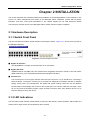
2.1 HARDWARE DESCRIPTION .................................................................................................................... 2-1
2.1.1 Switch Front Panel .................................................................................................................. 2-1
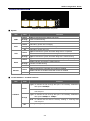
2.1.2 LED Indications ....................................................................................................................... 2-1
2.1.3 Switch Rear Panel ................................................................................................................... 2-3
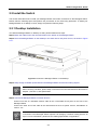
2.2 INSTALL THE SWITCH ........................................................................................................................... 2-4
2.2.1 Desktop Installation ................................................................................................................. 2-4
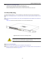
2.2.2 Rack Mounting ........................................................................................................................ 2-5
2.2.3 Installing the SFP transceiver ................................................................................................. 2-6
CHAPTER 3 SWITCH MANAGEMENT .......................................................................... 3-9
3.1 M ANAGEMENT OPTIONS ....................................................................................................................... 3-9
3.1.1 Out-Of-Band Management ...................................................................................................... 3-9
3.1.2 In-band Management ............................................................................................................ 3-12
3.2 CLI INTERFACE .................................................................................................................................. 3-18
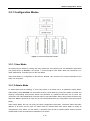
3.2.1 Configuration Modes ............................................................................................................. 3-19
3.2.2 Configuration Syntax ............................................................................................................. 3-21
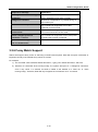
3.2.3 Shortcut Key Support ............................................................................................................ 3-21
3.2.4 Help Function ........................................................................................................................ 3-22
3.2.5 Input Verification .................................................................................................................... 3-22
3.2.6 Fuzzy Match Support ............................................................................................................ 3-23
CHAPTER 4 BASIC SWITCH CONFIGURATION .......................................................... 4-1
4.1 BASIC CONFIGURATION ........................................................................................................................ 4-1
4.2 TELNET M ANAGEMENT......................................................................................................................... 4-2
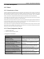
4.2.1 Telnet ....................................................................................................................................... 4-2
4.2.2 SSH ......................................................................................................................................... 4-3
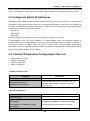
4.3 CONFIGURATE SWITCH IP ADDRESSES ................................................................................................. 4-5
4.3.1 Switch IP Addresses Configuration Task List .......................................................................... 4-5
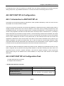
4.4 SNMP CONFIGURATION ....................................................................................................................... 4-6
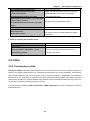
4.4.1 Introduction to SNMP .............................................................................................................. 4-6
4.4.2 Introduction to MIB .................................................................................................................. 4-8
4.4.3 Introduction to RMON ............................................................................................................. 4-9
1
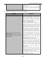
4.4.4 SNMP Configuration ............................................................................................................... 4-9
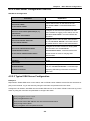
4.4.5 Typical SNMP Configuration Examples ................................................................................ 4-12
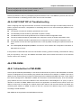
4.4.6 SNMP Troubleshooting ......................................................................................................... 4-13
4.5 SWITCH UPGRADE ............................................................................................................................. 4-14
4.5.1 Switch System Files .............................................................................................................. 4-14
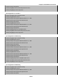
4.5.2 BootROM Upgrade ................................................................................................................ 4-14
4.5.3 FTP/TFTP Upgrade ............................................................................................................... 4-17
CHAPTER 5 FILE SYSTEM OPERATIONS .................................................................... 5-1
5.1 INTRODUCTION TO FILE STORAGE DEVICES........................................................................................... 5-1
5.2 FILE SYSTEM OPERATION CONFIGURATION TASK LIST ........................................................................... 5-1
5.3 TYPICAL APPLICATIONS........................................................................................................................ 5-3
5.4 TROUBLESHOOTING ............................................................................................................................. 5-3
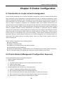
CHAPTER 6 CLUSTER CONFIGURATION .................................................................... 6-1
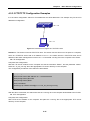
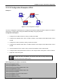
6.1 INTRODUCTION TO CLUSTER NETWORK MANAGEMENT............................................................................ 6-1
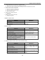
6.2 CLUSTER NETWORK MANAGEMENT CONFIGURATION SEQUENCE ........................................................... 6-1
6.3 EXAMPLES OF CLUSTER ADMINISTRATION ............................................................................................ 6-5
6.4 CLUSTER ADMINISTRATION TROUBLESHOOTING .................................................................................... 6-5
CHAPTER 7 PORT CONFIGURATION ........................................................................... 7-1
7.1 INTRODUCTION TO PORT ...................................................................................................................... 7-1
7.2 NETWORK PORT CONFIGURATION TASK LIST ........................................................................................ 7-1
7.3 PORT CONFIGURATION EXAMPLE ......................................................................................................... 7-3
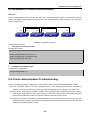
7.4 PORT TROUBLESHOOTING .................................................................................................................... 7-4
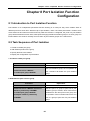
CHAPTER 8 PORT ISOLATION FUNCTION CONFIGURATION ................................... 8-1
8.1 INTRODUCTION TO PORT ISOLATION FUNCTION...................................................................................... 8-1
8.2 TASK SEQUENCE OF PORT ISOLATION................................................................................................... 8-1
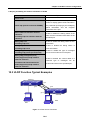
8.3 PORT ISOLATION FUNCTION TYPICAL EXAMPLES ................................................................................... 8-2
CHAPTER 9 PORT LOOPBACK DETECTION FUNCTION CONFIGURATION ............ 9-3
9.1 INTRODUCTION TO PORT LOOPBACK DETECTION FUNCTION .................................................................. 9-3
9.2 PORT LOOPBACK DETECTION FUNCTION CONFIGURATION TASK LIST .................................................... 9-3
9.3 PORT LOOPBACK DETECTION FUNCTION EXAMPLE ............................................................................... 9-5
9.4 PORT LOOPBACK DETECTION TROUBLESHOOTING ................................................................................ 9-6
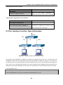
CHAPTER 10 ULDP FUNCTION CONFIGURATION ....................................................10-1
10.1 INTRODUCTION TO ULDP FUNCTION ................................................................................................. 10-1
10.2 ULDP CONFIGURATION TASK SEQUENCE ......................................................................................... 10-2
2
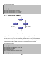
10.3 ULDP FUNCTION TYPICAL EXAMPLES .............................................................................................. 10-4
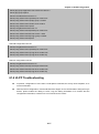
10.4 ULDP TROUBLESHOOTING .............................................................................................................. 10-5
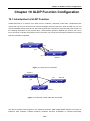
CHAPTER 11 LLDP FUNCTION OPERATION CONFIGURATION ............................... 11-1
11.1 INTRODUCTION TO LLDP FUNCTION ................................................................................................. 11-1
11.2 LLDP FUNCTION CONFIGURATION TASK SEQUENCE ......................................................................... 11-2
11.3 LLDP FUNCTION TYPICAL EXAMPLE................................................................................................. 11-5
11.4 LLDP FUNCTION TROUBLESHOOTING ............................................................................................... 11-5
CHAPTER 12 PORT CHANNEL CONFIGURATION .....................................................12-1
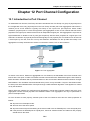
12.1 INTRODUCTION TO PORT CHANNEL ................................................................................................... 12-1
12.2 BRIEF INTRODUCTION TO LACP ....................................................................................................... 12-2
12.2.1 Static LACP Aggregation ..................................................................................................... 12-2
12.2.2 Dynamic LACP Aggregation ................................................................................................ 12-3
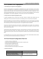
12.3 PORT CHANNEL CONFIGURATION TASK LIST ..................................................................................... 12-3
12.4 PORT CHANNEL EXAMPLES.............................................................................................................. 12-5
12.5 PORT CHANNEL TROUBLESHOOTING ................................................................................................ 12-7
CHAPTER 13 JUMBO CONFIGURATION .....................................................................13-1
13.1 INTRODUCTION TO JUMBO ................................................................................................................ 13-1
13.2 JUMBO CONFIGURATION TASK SEQUENCE ........................................................................................ 13-1
CHAPTER 14 VLAN CONFIGURATION ........................................................................14-1
14.1 VLAN CONFIGURATION ................................................................................................................... 14-1
14.1.1 Introduction to VLAN ........................................................................................................... 14-1
14.1.2 VLAN Configuration Task List ............................................................................................. 14-2
14.1.3 Typical VLAN Application .................................................................................................... 14-4
14.1.4 Typical Application of Hybrid Port........................................................................................ 14-6
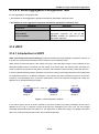
14.2 GVRP CONFIGURATION ................................................................................................................... 14-8
14.2.1 Introduction to GVRP .......................................................................................................... 14-8
14.2.2 GVRP Configuration Task List ............................................................................................. 14-8
14.2.3 Typical GVRP Application ................................................................................................... 14-9
14.2.4 GVRP Troubleshooting ..................................................................................................... 14-11
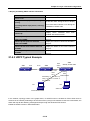
14.3 DOT1Q-TUNNEL CONFIGURATION ................................................................................................... 14-11
14.3.1 Introduction to Dot1q-tunnel .............................................................................................. 14-11
14.3.2 Dot1q-tunnel Configuration ............................................................................................... 14-12
14.3.3 Typical Applications of the Dot1q-tunnel ........................................................................... 14-12
14.4 VLAN-TRANSLATION CONFIGURATION ............................................................................................ 14-14
14.4.1 Introduction to VLAN-translation ....................................................................................... 14-14
14.4.2 VLAN-translation Configuration ........................................................................................ 14-14
14.4.3 Typical application of VLAN-translation ............................................................................ 14-15
3
14.4.4 VLAN-translation Troubleshooting .................................................................................... 14-16
14.5 DYNAMIC VLAN CONFIGURATION................................................................................................... 14-16
14.5.1 Introduction to Dynamic VLAN .......................................................................................... 14-16
14.5.2 Dynamic VLAN Configuration ........................................................................................... 14-16
14.5.3 Typical Application of the Dynamic VLAN ......................................................................... 14-19
14.5.4 Dynamic VLAN Troubleshooting ....................................................................................... 14-20
14.6 VOICE VLAN CONFIGURATION ....................................................................................................... 14-20
14.6.1 Introduction to Voice VLAN ............................................................................................... 14-20
14.6.2 Voice VLAN Configuration................................................................................................. 14-21
14.6.3 Typical Applications of the Voice VLAN ............................................................................ 14-21
14.6.4 Voice VLAN Troubleshooting ............................................................................................ 14-22
CHAPTER 15 MAC TABLE CONFIGURATION .............................................................15-1
15.1 INTRODUCTION TO MAC TABLE ........................................................................................................ 15-1
15.1.1 Obtaining MAC Table .......................................................................................................... 15-1
15.1.2 Forward or Filter .................................................................................................................. 15-2
15.2 M AC ADDRESS TABLE CONFIGURATION TASK LIST............................................................................ 15-3
15.3 TYPICAL CONFIGURATION EXAMPLES ............................................................................................... 15-4
15.4 MAC TABLE TROUBLESHOOTING ..................................................................................................... 15-5
15.5 MAC ADDRESS FUNCTION EXTENSION ............................................................................................. 15-5
15.5.1 MAC Address Binding ......................................................................................................... 15-5
CHAPTER 16 MSTP CONFIGURATION ........................................................................16-1
16.1 INTRODUCTION TO MSTP ................................................................................................................. 16-1
16.1.1 MSTP Region ...................................................................................................................... 16-1
16.1.2 Port Roles............................................................................................................................ 16-3
16.1.3 MSTP Load Balance ........................................................................................................... 16-3
16.2 MSTP CONFIGURATION TASK LIST ................................................................................................... 16-3
16.3 MSTP EXAMPLE.............................................................................................................................. 16-7
16.4 MSTP TROUBLESHOOTING ............................................................................................................ 16-11
CHAPTER 17 QOS CONFIGURATION ..........................................................................17-1
17.1 INTRODUCTION TO QOS ................................................................................................................... 17-1
17.1.1 QoS Terms .......................................................................................................................... 17-1
17.1.2 QoS Implementation ........................................................................................................... 17-2
17.1.3 Basic QoS Model ................................................................................................................ 17-2
17.2 QOS CONFIGURATION TASK LIST ..................................................................................................... 17-5
17.3 QOS EXAMPLE .............................................................................................................................. 17-10
17.4 QOS TROUBLESHOOTING ............................................................................................................... 17-12
CHAPTER 18 PBR CONFIGURATION ..........................................................................18-1
4
18.1 INTRODUCTION TO PBR ................................................................................................................... 18-1
18.2 PBR CONFIGURATION ...................................................................................................................... 18-1
18.3 PBR EXAMPLES .............................................................................................................................. 18-1
CHAPTER 19 IPV6 PBR CONFIGURATION .................................................................19-1
19.1 INTRODUCTION TO PBR(POLICY-BASED ROUTER) ............................................................................. 19-1
19.2 PBR CONFIGURATION TASK SEQUENCE ........................................................................................... 19-1
19.3 PBR EXAMPLES .............................................................................................................................. 19-3
19.4 PBR TROUBLESHOOTING HELP ....................................................................................................... 19-3
CHAPTER 20 FLOW-BASED REDIRECTION ...............................................................20-4
20.1 INTRODUCTION TO FLOW-BASED REDIRECTION ................................................................................. 20-4
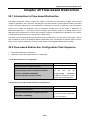
20.2 FLOW-BASED REDIRECTION CONFIGURATION TASK SEQUENCE ......................................................... 20-4
20.3 FLOW-BASED REDIRECTION EXAMPLES ............................................................................................ 20-5
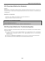
20.4 FLOW-BASED REDIRECTION TROUBLESHOOTING HELP...................................................................... 20-5
CHAPTER 21 LAYER 3 FORWARD CONFIGURATION ...............................................21-1
21.1 LAYER 3 INTERFACE ......................................................................................................................... 21-1
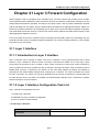
21.1.1 Introduction to Layer 3 Interface ......................................................................................... 21-1
21.1.2 Layer 3 Interface Configuration Task List ............................................................................ 21-1
21.2 IP CONFIGURATION .......................................................................................................................... 21-2
21.2.1 Introduction to IPv4, IPv6 .................................................................................................... 21-2
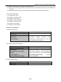
21.2.2 IP Configuration................................................................................................................... 21-4
21.2.3 IP Configuration Examples................................................................................................ 21-10
21.2.4 IPv6 Troubleshooting ........................................................................................................ 21-15
21.3 IP FORWARDING ............................................................................................................................ 21-15
21.3.1 Introduction to IP Forwarding ............................................................................................ 21-15
21.3.2 IP Route Aggregation Configuration Task ......................................................................... 21-16
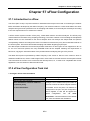
21.4 URPF ........................................................................................................................................... 21-16
21.4.1 Introduction to URPF......................................................................................................... 21-16
21.4.2 URPF Configuration Task Sequence ................................................................................ 21-17
21.4.3 URPF Typical Example ..................................................................................................... 21-18
21.4.4 URPF Troubleshooting ...................................................................................................... 21-19
21.5 ARP ............................................................................................................................................. 21-19
21.5.1 Introduction to ARP ........................................................................................................... 21-19
21.5.2 ARP Configuration Task List .............................................................................................. 21-19
21.5.3 ARP Troubleshooting ........................................................................................................ 21-21
CHAPTER 22 ARP SCANNING PREVENTION FUNCTION CONFIGURATION ..........22-1
22.1 INTRODUCTION TO ARP SCANNING PREVENTION FUNCTION .............................................................. 22-1
22.2 ARP SCANNING PREVENTION CONFIGURATION TASK SEQUENCE ...................................................... 22-1
5
22.3 ARP SCANNING PREVENTION TYPICAL EXAMPLES............................................................................ 22-3
22.4 ARP SCANNING PREVENTION TROUBLESHOOTING HELP ................................................................... 22-4
CHAPTER 23 PREVENT ARP, ND SPOOFING CONFIGURATION ..............................23-1
23.1 OVERVIEW ....................................................................................................................................... 23-1
23.1.1 ARP (Address Resolution Protocol) .................................................................................... 23-1
23.1.2 ARP Spoofing ...................................................................................................................... 23-1
23.1.3 How to prevent void ARP/ND Spoofing ............................................................................... 23-1
23.2 PREVENT ARP, ND SPOOFING CONFIGURATION ................................................................................ 23-2
23.3 PREVENT ARP, ND SPOOFING EXAMPLE .......................................................................................... 23-3
CHAPTER 24 ARP GUARD CONFIGURATION ............................................................24-1
24.1 INTRODUCTION TO ARP GUARD ..................................................................................................... 24-1
24.2 ARP GUARD CONFIGURATION TASK LIST ....................................................................................... 24-2
CHAPTER 25 ARP LOCAL PROXY CONFIGURATION................................................25-1
25.1 INTRODUCTION TO ARP LOCAL PROXY FUNCTION ............................................................................. 25-1
25.2 ARP LOCAL PROXY FUNCTION CONFIGURATION TASK LIST............................................................... 25-2
25.3 TYPICAL EXAMPLES OF ARP LOCAL PROXY FUNCTION ..................................................................... 25-2
25.4 ARP LOCAL PROXY FUNCTION TROUBLESHOOTING .......................................................................... 25-3
CHAPTER 26 GRATUITOUS ARP CONFIGURATION ..................................................26-1
26.1 INTRODUCTION TO GRATUITOUS ARP ............................................................................................... 26-1
26.2 GRATUITOUS ARP CONFIGURATION TASK LIST ................................................................................. 26-1
26.3 GRATUITOUS ARP CONFIGURATION EXAMPLE .................................................................................. 26-2
26.4 GRATUITOUS ARP TROUBLESHOOTING ............................................................................................ 26-2
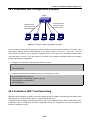
CHAPTER 27 ND SNOOPING CONFIGURATION ........................................................27-1
27.1 INTRODUCTION TO ND SNOOPING ..................................................................................................... 27-1
27.2 ND SNOOPING BASIC CONFIGURATION ............................................................................................. 27-1
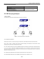
27.3 ND SNOOPING EXAMPLE ................................................................................................................. 27-3
27.4 ND SNOOPING TROUBLESHOOTING .................................................................................................. 27-4
CHAPTER 28 DHCP CONFIGURATION .......................................................................28-5
28.1 INTRODUCTION TO DHCP ................................................................................................................. 28-5
28.2 DHCP SERVER CONFIGURATION ...................................................................................................... 28-6
28.3 DHCP RELAY CONFIGURATION ........................................................................................................ 28-8
28.4 DHCP CONFIGURATION EXAMPLES .................................................................................................. 28-9
28.5 DHCP TROUBLESHOOTING ............................................................................................................ 28-11
6
CHAPTER 29 DHCPV6 CONFIGURATION ...................................................................29-1
29.1 INTRODUCTION TO DHCPV6 ............................................................................................................. 29-1
29.2 DHCPV6 SERVER CONFIGURATION .................................................................................................. 29-2
29.3 DHCPV6 RELAY DELEGATION CONFIGURATION ................................................................................ 29-3
29.4 DHCPV6 PREFIX DELEGATION SERVER CONFIGURATION .................................................................. 29-4
29.5 DHCPV6 PREFIX DELEGATION CLIENT CONFIGURATION ................................................................... 29-6
29.6 DHCPV6 CONFIGURATION EXAMPLES .............................................................................................. 29-6
29.7 DHCPV6 TROUBLESHOOTING ........................................................................................................ 29-10
CHAPTER 30 DHCP OPTION 82 CONFIGURATION ....................................................30-1
30.1 INTRODUCTION TO DHCP OPTION 82 ................................................................................................ 30-1
30.1.1 DHCP option 82 Message Structure ................................................................................... 30-1
30.1.2 option 82 Working Mechanism ............................................................................................ 30-2
30.2 DHCP OPTION 82 CONFIGURATION TASK LIST .................................................................................. 30-2
30.3 DHCP OPTION 82 APPLICATION EXAMPLES ...................................................................................... 30-4
CHAPTER 31 DHCP SNOOPING CONFIGURATION ...................................................31-6
31.1 INTRODUCTION TO DHCP SNOOPING ................................................................................................ 31-6
31.2 DHCP SNOOPING CONFIGURATION TASK SEQUENCE ........................................................................ 31-7
31.3 DHCP SNOOPING TYPICAL APPLICATION........................................................................................ 31-10
31.4 DHCP SNOOPING TROUBLESHOOTING HELP .................................................................................. 31-10
31.4.1 Monitor and Debug Information ........................................................................................ 31-10
31.4.2 DHCP Snooping Troubleshooting Help ............................................................................. 31-11
CHAPTER 32 DHCPV6 SNOOPING CONFIGURATION ...............................................32-1
32.1 INTRODUCTION TO DHCPV6 SNOOPING ............................................................................................ 32-1
32.1.1 Defense against Fake DHCPv6 Server .............................................................................. 32-1
32.1.2 Defense against Fake IPv6 Address ................................................................................... 32-1
32.1.3 Defense against the attack of DHCPv6 addresses exhaustion .......................................... 32-1
32.1.4 Defense against ND cheat .................................................................................................. 32-1
32.1.5 Reply the remove requirement for port ............................................................................... 32-1
32.2 DHCPV6 SNOOPING CONFIGURATION TASK SEQUENCE .................................................................... 32-2
32.3 DHCPV6 SNOOPING TYPICAL APPLICATION ..................................................................................... 32-5
32.4 DHCPV6 SNOOPING TROUBLESHOOTING ......................................................................................... 32-6
32.4.1 Monitor and Debug Information .......................................................................................... 32-6
32.4.2 DHCPv6 Snooping Troubleshooting Help ........................................................................... 32-6
CHAPTER 33 ROUTING PROTOCOL OVERVIEW .......................................................33-1
33.1 ROUTING TABLE .............................................................................................................................. 33-1
33.2 IP ROUTING POLICY ......................................................................................................................... 33-2
7
33.2.1 Introduction to Routing Policy ............................................................................................. 33-2
33.2.2 IP Routing Policy Configuration Task List ........................................................................... 33-4
33.2.3 Configuration Examples ...................................................................................................... 33-7
33.2.4 Troubleshooting ................................................................................................................... 33-8
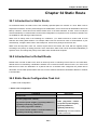
CHAPTER 34 STATIC ROUTE.......................................................................................34-1
34.1 INTRODUCTION TO STATIC ROUTE ..................................................................................................... 34-1
34.2 INTRODUCTION TO DEFAULT ROUTE .................................................................................................. 34-1
34.3 STATIC ROUTE CONFIGURATION TASK LIST ....................................................................................... 34-1
34.4 STATIC ROUTE CONFIGURATION EXAMPLES ...................................................................................... 34-2
CHAPTER 35 RIP ..........................................................................................................35-1
35.1 INTRODUCTION TO RIP ..................................................................................................................... 35-1
35.2 RIP CONFIGURATION TASK LIST ....................................................................................................... 35-2
35.3 RIP EXAMPLES................................................................................................................................ 35-9
35.3.1 Typical RIP Examples ......................................................................................................... 35-9
35.3.2 Typical Examples of RIP aggregation function ................................................................. 35-10
35.4 RIP TROUBLESHOOTING ................................................................................................................ 35-11
CHAPTER 36 RIPNG .....................................................................................................36-1
36.1 INTRODUCTION TO RIPNG ................................................................................................................ 36-1
36.2 RIPNG CONFIGURATION TASK LIST................................................................................................... 36-2
36.3 RIPNG CONFIGURATION EXAMPLES .................................................................................................. 36-7
36.3.1 Typical RIPng Examples ..................................................................................................... 36-7
36.3.2 RIPng Aggregation Route Function Typical Examples ....................................................... 36-8
36.4 RIPNG TROUBLESHOOTING .............................................................................................................. 36-9
CHAPTER 37 OSPF .......................................................................................................37-1
37.1 INTRODUCTION TO OSPF ................................................................................................................. 37-1
37.2 OSPF CONFIGURATION TASK LIST ................................................................................................... 37-4
37.3 OSPF EXAMPLES ............................................................................................................................ 37-9
37.3.1 Configuration Example of OSPF ......................................................................................... 37-9
37.3.2 Configuration Examples of OSPF VPN ............................................................................. 37-17
37.4 OSPF TROUBLESHOOTING ............................................................................................................ 37-19
CHAPTER 38 OSPFV3 ..................................................................................................38-1
38.1 INTRODUCTION TO OSPFV3 ............................................................................................................. 38-1
38.2 OSPFV3 CONFIGURATION TASK LIST ............................................................................................... 38-4
38.3 OSPFV3 EXAMPLES ........................................................................................................................ 38-8
38.4 OSPFV3 TROUBLESHOOTING ........................................................................................................ 38-10
8
CHAPTER 39 BGP .........................................................................................................39-1
39.1 INTRODUCTION TO BGP ................................................................................................................... 39-1
39.2 BGP CONFIGURATION TASK LIST ..................................................................................................... 39-4
39.3 CONFIGURATION EXAMPLES OF BGP ............................................................................................. 39-16
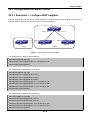
39.3.1 Examples 1: configure BGP neighbor ............................................................................... 39-16
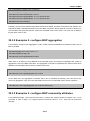
39.3.2 Examples 2: configure BGP aggregation .......................................................................... 39-17
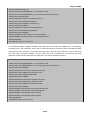
39.3.3 Examples 3: configure BGP community attributes............................................................ 39-17
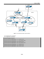
39.3.4 Examples 4: configure BGP confederation ....................................................................... 39-19
39.3.5 Examples 5: configure BGP route reflector ....................................................................... 39-20
39.3.6 Examples 6: configure MED of BGP ................................................................................. 39-22
39.3.7 Examples 7: example of BGP VPN ................................................................................... 39-24
39.4 BGP TROUBLESHOOTING .............................................................................................................. 39-28
CHAPTER 40 MBGP4+ ..................................................................................................40-1
40.1 INTRODUCTION TO MBGP4+ ............................................................................................................ 40-1
40.2 MBGP4+ CONFIGURATION TASK LIST .............................................................................................. 40-1
40.3 MBGP4+ EXAMPLES....................................................................................................................... 40-2
40.4 MBGP4+ TROUBLESHOOTING ......................................................................................................... 40-4
CHAPTER 41 BLACK HOLE ROUTING MANUAL .......................................................41-1
41.1 INTRODUCTION TO BLACK HOLE ROUTING ........................................................................................ 41-1
41.2 IPV4 BLACK HOLE ROUTING CONFIGURATION TASK ......................................................................... 41-1
41.3 IPV6 BLACK HOLE ROUTING CONFIGURATION TASK ......................................................................... 41-1
41.4 BLACK HOLE ROUTING CONFIGURATION EXMAPLES ......................................................................... 41-2
41.5 BLACK HOLE ROUTING TROUBLESHOOTING ..................................................................................... 41-3
CHAPTER 42 ECMP CONFIGURATION .......................................................................42-1
42.1 INTRODUCTION TO ECMP ................................................................................................................ 42-1
42.2 ECMP CONFIGURATION TASK LIST .................................................................................................. 42-1
42.3 ECMP TYPICAL EXAMPLE................................................................................................................ 42-2
42.3.1 Static Route Implements ECMP .......................................................................................... 42-2
42.3.2 OSPF Implements ECMP ................................................................................................... 42-3
CHAPTER 43 IPV4 MULTICAST PROTOCOL ..............................................................43-1
43.1 IPV4 MULTICAST PROTOCOL OVERVIEW ........................................................................................... 43-1
43.1.1 Introduction to Multicast ...................................................................................................... 43-1
43.1.2 Multicast Address ................................................................................................................ 43-1
43.1.3 IP Multicast Packet Transmission ....................................................................................... 43-3
43.1.4 IP Multicast Application ....................................................................................................... 43-3
43.2 PIM-DM .......................................................................................................................................... 43-3
43.2.1 Introduction to PIM-DM ....................................................................................................... 43-3
9
43.2.2 PIM-DM Configuration Task List.......................................................................................... 43-5
43.2.3 PIM-DM Configuration Examples ........................................................................................ 43-7
43.2.4 PIM-DM Troubleshooting .................................................................................................... 43-8
43.3 PIM-SM .......................................................................................................................................... 43-8
43.3.1 Introduction to PIM-SM ....................................................................................................... 43-8
43.3.2 PIM-SM Configuration Task List .......................................................................................... 43-9
43.3.3 PIM-SM Configuration Examples ...................................................................................... 43-13
43.3.4 PIM-SM Troubleshooting................................................................................................... 43-14
43.4 MSDP CONFIGURATION ................................................................................................................. 43-15
43.4.1 Introduction to MSDP ........................................................................................................ 43-15
43.4.2 Brief Introduction to MSDP Configuration Tasks ............................................................... 43-16
43.4.3 Configuration of MSDP Basic Function ............................................................................. 43-16
43.4.4 Configuration of MSDP Entities ......................................................................................... 43-17
43.4.5 Configuration of Delivery of MSDP Packet ....................................................................... 43-18
43.4.6 Configuration of Parameters of SA-cache ........................................................................ 43-19
43.4.7 MSDP Configuration Examples......................................................................................... 43-19
43.4.8 MSDP Troubleshooting ..................................................................................................... 43-25
43.5 ANYCAST RP CONFIGURATION .................................................................................................... 43-25
43.5.1 Introduction to ANYCAST RP............................................................................................ 43-25
43.5.2 ANYCAST RP Configuration Task ..................................................................................... 43-25
43.5.3 ANYCAST RP Configuration Examples ............................................................................ 43-28
43.5.4 ANYCAST RP Troubleshooting ......................................................................................... 43-29
43.6 PIM-SSM ..................................................................................................................................... 43-30
43.6.1 Introduction to PIM-SSM ................................................................................................... 43-30
43.6.2 PIM-SSM Configuration Task List ..................................................................................... 43-30
43.6.3 PIM-SSM Configuration Examples ................................................................................... 43-30
43.6.4 PIM-SSM Troubleshooting ................................................................................................ 43-32
43.7 DVMRP ........................................................................................................................................ 43-33
43.7.1 Introduction to DVMRP ..................................................................................................... 43-33
43.7.2 DVMRP Configuration Task List ........................................................................................ 43-34
43.7.3 DVMRP Configuration Examples ...................................................................................... 43-36
43.7.4 DVMRP Troubleshooting ................................................................................................... 43-36
43.8 DCSCM ........................................................................................................................................ 43-37
43.8.1 Introduction to DCSCM ..................................................................................................... 43-37
43.8.2 DCSCM Configuration Task List........................................................................................ 43-38
43.8.3 DCSCM Configuration Examples ...................................................................................... 43-40
43.8.4 DCSCM Troubleshooting .................................................................................................. 43-41
43.9 IGMP............................................................................................................................................ 43-41
43.9.1 Introduction to IGMP ......................................................................................................... 43-41
43.9.2 IGMP Configuration Task List............................................................................................ 43-43
43.9.3 IGMP Configuration Examples .......................................................................................... 43-45
43.9.4 IGMP Troubleshooting ...................................................................................................... 43-46
43.10 IGMP SNOOPING ......................................................................................................................... 43-46
10
43.10.1 Introduction to IGMP Snooping ....................................................................................... 43-46
43.10.2 IGMP Snooping Configuration Task List ......................................................................... 43-47
43.10.3 IGMP Snooping Examples .............................................................................................. 43-49
43.10.4 IGMP Snooping Troubleshooting .................................................................................... 43-51
43.11 IGMP PROXY CONFIGURATION ..................................................................................................... 43-52
43.11.1 Introduction to IGMP Proxy ............................................................................................. 43-52
43.11.2 IGMP Proxy Configuration Task List................................................................................ 43-52
43.11.3 IGMP Proxy Examples .................................................................................................... 43-54
43.11.4 IGMP Proxy Troubleshooting .......................................................................................... 43-56
CHAPTER 44 IPV6 MULTICAST PROTOCOL ..............................................................44-1
44.1 PIM-DM6........................................................................................................................................ 44-1
44.1.1 Introduction to PIM-DM6 ..................................................................................................... 44-1
44.1.2 PIM-DM6 Configuration Task List........................................................................................ 44-2
44.1.3 PIM-DM6 Typical Application .............................................................................................. 44-4
44.1.4 PIM-DM6 Troubleshooting .................................................................................................. 44-5
44.2 PIM-SM6 ........................................................................................................................................ 44-6
44.2.1 Introduction to PIM-SM6 ..................................................................................................... 44-6
44.2.2 PIM-SM6 Configuration Task List ........................................................................................ 44-7
44.2.3 PIM-SM6 Typical Application............................................................................................. 44-11
44.2.4 PIM-SM6 Troubleshooting................................................................................................. 44-12
44.3 ANYCAST RP V6 CONFIGURATION ............................................................................................... 44-13
44.3.1 Introduction to ANYCAST RP v6 ....................................................................................... 44-13
44.3.2 ANYCAST RP v6 Configuration Task ................................................................................ 44-13
44.3.3 ANYCAST RP v6 Configuration Examples ....................................................................... 44-16
44.3.4 ANYCAST RP v6 Troubleshooting .................................................................................... 44-17
44.4 PIM-SSM6 ................................................................................................................................... 44-17
44.4.1 Introduction to PIM-SSM6 ................................................................................................. 44-17
44.4.2 PIM-SSM6 Configuration Task List ................................................................................... 44-18
44.4.3 PIM-SSM6 Configuration Example ................................................................................... 44-18
44.4.4 PIM-SSM6 Troubleshooting .............................................................................................. 44-20
44.5 IPV6 DCSCM ............................................................................................................................... 44-20
44.5.1 Introduction to IPv6 DCSCM ............................................................................................. 44-20
44.5.2 IPv6 DCSCM Configuration Task Sequence ..................................................................... 44-21
44.5.3 IPv6 DCSCM Typical Examples ........................................................................................ 44-24
44.5.4 IPv6 DCSCM Troubleshooting .......................................................................................... 44-25
44.6 MLD ............................................................................................................................................. 44-25
44.6.1 Introduction to MLD ........................................................................................................... 44-25
44.6.2 MLD Configuration Task List ............................................................................................. 44-25
44.6.3 MLD Typical Application .................................................................................................... 44-27
44.6.4 MLD Troubleshooting Help................................................................................................ 44-28
44.7 MLD SNOOPING ............................................................................................................................ 44-28
44.7.1 Introduction to MLD Snooping........................................................................................... 44-28
44.7.2 MLD Snooping Configuration Task.................................................................................... 44-29
11
44.7.3 MLD Snooping Examples.................................................................................................. 44-30
44.7.4 MLD Snooping Troubleshooting ........................................................................................ 44-33
CHAPTER 45 MULTICAST VLAN .................................................................................45-1
45.1 INTRODUCTIONS TO MULTICAST VLAN ............................................................................................. 45-1
45.2 MULTICAST VLAN CONFIGURATION TASK LIST ................................................................................. 45-1
45.3 MULTICAST VLAN EXAMPLES .......................................................................................................... 45-2
CHAPTER 46 ACL CONFIGURATION ..........................................................................46-1
46.1 INTRODUCTION TO ACL.................................................................................................................... 46-1
46.1.1 Access-list ........................................................................................................................... 46-1
46.1.2 Access-group ...................................................................................................................... 46-1
46.1.3 Access-list Action and Global Default Action....................................................................... 46-1
46.2 ACL CONFIGURATION TASK LIST...................................................................................................... 46-2
46.3 ACL EXAMPLE .............................................................................................................................. 46-17
46.4 ACL TROUBLESHOOTING ............................................................................................................... 46-21
CHAPTER 47 802.1X CONFIGURATION ......................................................................47-1
47.1 INTRODUCTION TO 802.1X ................................................................................................................ 47-1
47.1.1 The Authentication Structure of 802.1x ............................................................................... 47-1
47.1.2 The Work Mechanism of 802.1x ......................................................................................... 47-3
47.1.3 The Encapsulation of EAPOL Messages ............................................................................ 47-3
47.1.4 The Encapsulation of EAP Attributes .................................................................................. 47-5
47.1.5 Web Authentication Proxy based on 802.1x ....................................................................... 47-5
47.1.6 The Authentication Methods of 802.1x ................................................................................ 47-6
47.1.7 The Extension and Optimization of 802.1x ....................................................................... 47-11
47.1.8 The Features of VLAN Allocation ...................................................................................... 47-12
47.2 802.1X CONFIGURATION TASK LIST ................................................................................................ 47-13
47.3 802.1X APPLICATION EXAMPLE ...................................................................................................... 47-16
47.3.1 Examples of Guest Vlan Applications ............................................................................... 47-16
47.3.2 Examples of IPv4 Radius Applications .............................................................................. 47-19
47.3.3 Examples of IPv6 Radius Application ............................................................................... 47-20
47.3.4 802.1x Web Proxy Authentication Sample Application ..................................................... 47-21
47.4 802.1X TROUBLESHOOTING ........................................................................................................... 47-22
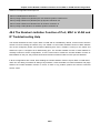
CHAPTER 48 THE NUMBER LIMITATION FUNCTION OF PORT, MAC IN VLAN AND IP
CONFIGURATION ..........................................................................................................48-1
48.1 INTRODUCTION TO THE NUMBER LIMITATION FUNCTION OF PORT, MAC IN VLAN AND IP .................... 48-1
48.2 THE NUMBER LIMITATION FUNCTION OF PORT, MAC IN VLAN AND IP CONFIGURATION TASK SEQUENCE
............................................................................................................................................................... 48-2
48.3 THE NUMBER LIMITATION FUNCTION OF PORT, MAC IN VLAN AND IP TYPICAL EXAMPLES ................. 48-4
48.4 THE NUMBER LIMITATION FUNCTION OF PORT, MAC IN VLAN AND IP TROUBLESHOOTING HELP ........ 48-5
12
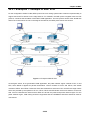
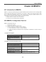
CHAPTER 49 OPERATIONAL CONFIGURATION OF AM FUNCTION ........................49-1
49.1 INTRODUCTION TO AM FUNCTION ..................................................................................................... 49-1
49.2 AM FUNCTION CONFIGURATION TASK LIST ....................................................................................... 49-1
49.3 AM FUNCTION EXAMPLE .................................................................................................................. 49-3
49.4 AM FUNCTION TROUBLESHOOTING .................................................................................................. 49-3
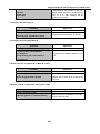
CHAPTER 50 SECURITY FEATURE CONFIGURATION ..............................................50-1
50.1 INTRODUCTION TO SECURITY FEATURE ............................................................................................. 50-1
50.2 SECURITY FEATURE CONFIGURATION ............................................................................................... 50-1
50.2.1 Prevent IP Spoofing Function Configuration Task Sequence ............................................. 50-1
50.2.2 Prevent TCP Unauthorized Label Attack Function Configuration Task Sequence ............. 50-1
50.2.3 Anti Port Cheat Function Configuration Task Sequence ..................................................... 50-2
50.2.4 Prevent TCP Fragment Attack Function Configuration Task Sequence ............................. 50-2
50.2.5 Prevent ICMP Fragment Attack Function Configuration Task Sequence ........................... 50-3
50.3 SECURITY FEATURE EXAMPLE .......................................................................................................... 50-3
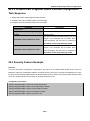
CHAPTER 51 TACACS+ CONFIGURATION .................................................................51-1
51.1 INTRODUCTION TO TACACS+ .......................................................................................................... 51-1
51.2 TACACS+ CONFIGURATION TASK LIST ............................................................................................ 51-1
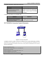
51.3 TACACS+ SCENARIOS TYPICAL EXAMPLES..................................................................................... 51-2
51.4 TACACS+ TROUBLESHOOTING ....................................................................................................... 51-3
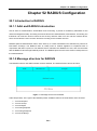
CHAPTER 52 RADIUS CONFIGURATION ....................................................................52-1
52.1 INTRODUCTION TO RADIUS ............................................................................................................. 52-1
52.1.1 AAA and RADIUS Introduction ............................................................................................ 52-1
52.1.2 Message structure for RADIUS ........................................................................................... 52-1
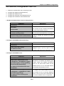
52.2 RADIUS CONFIGURATION TASK LIST ............................................................................................... 52-3
52.3 RADIUS TYPICAL EXAMPLES .......................................................................................................... 52-5
52.3.1 IPv4 Radius Example .......................................................................................................... 52-5
52.3.2 IPv6 RadiusExample ........................................................................................................... 52-6
52.4 RADIUS TROUBLESHOOTING .......................................................................................................... 52-6
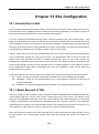
CHAPTER 53 SSL CONFIGURATION ...........................................................................53-1
53.1 INTRODUCTION TO SSL .................................................................................................................... 53-1
53.1.1 Basic Element of SSL ......................................................................................................... 53-1
53.2 SSL CONFIGURATION TASK LIST ...................................................................................................... 53-2
53.3 SSL TYPICAL EXAMPLE ................................................................................................................... 53-3
53.4 SSL TROUBLESHOOTING ................................................................................................................. 53-4
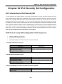
CHAPTER 54 IPV6 SECURITY RA CONFIGURATION .................................................54-1
13
54.1 INTRODUCTION TO IPV6 SECURITY RA.............................................................................................. 54-1
54.2 IPV6 SECURITY RA CONFIGURATION TASK SEQUENCE ...................................................................... 54-1
54.3 IPV6 SECURITY RA TYPICAL EXAMPLES ........................................................................................... 54-2
54.4 IPV6 SECURITY RA TROUBLESHOOTING HELP .................................................................................. 54-2
CHAPTER 55 VLAN-ACL CONFIGURATION ...............................................................55-1
55.1 INTRODUCTION TO VLAN-ACL ........................................................................................................ 55-1
55.2 VLAN-ACL CONFIGURATION TASK LIST .......................................................................................... 55-1
55.3 VLAN-ACL CONFIGURATION EXAMPLE............................................................................................ 55-3
55.4 VLAN-ACL TROUBLESHOOTING ...................................................................................................... 55-4
55.5 INTRODUCTION TO MIRROR............................................................................................................... 55-4
55.6 MIRROR CONFIGURATION TASK LIST................................................................................................. 55-5
55.7 MIRROR EXAMPLES ......................................................................................................................... 55-6
55.8 DEVICE MIRROR TROUBLESHOOTING................................................................................................ 55-6
CHAPTER 56 RSPAN CONFIGURATION .....................................................................56-1
56.1 INTRODUCTION TO RSPAN .............................................................................................................. 56-1
56.2 RSPAN CONFIGURATION TASK LIST ................................................................................................ 56-2
56.3 TYPICAL EXAMPLES OF RSPAN ....................................................................................................... 56-4
56.4 RSPAN TROUBLESHOOTING ............................................................................................................ 56-7
CHAPTER 57 SFLOW CONFIGURATION .....................................................................57-1
57.1 INTRODUCTION TO SFLOW ................................................................................................................ 57-1
57.2 SFLOW CONFIGURATION TASK LIST .................................................................................................. 57-1
57.3 SFLOW EXAMPLES ........................................................................................................................... 57-3
57.4 SFLOW TROUBLESHOOTING ............................................................................................................. 57-4
CHAPTER 58 VRRP CONFIGURATION ........................................................................58-1
58.1 INTRODUCTION TO VRRP ................................................................................................................. 58-1
58.2 VRRP CONFIGURATION TASK LIST ................................................................................................... 58-2
58.3 VRRP TYPICAL EXAMPLES .............................................................................................................. 58-3
58.4 VRRP TROUBLESHOOTING .............................................................................................................. 58-4
CHAPTER 59 IPV6 VRRPV3 CONFIGURATION...........................................................59-1
59.1 INTRODUCTION TO VRRPV3 ............................................................................................................. 59-1
59.1.1 The Format of VRRPv3 Message ....................................................................................... 59-2
59.1.2 VRRPv3 Working Mechanism ............................................................................................. 59-3
59.2 VRRPV3 CONFIGURATION ............................................................................................................... 59-4
14
59.2.1 Configuration Task Sequence ............................................................................................. 59-4
59.3 VRRPV3 TYPICAL EXAMPLES .......................................................................................................... 59-5
59.4 VRRPV3 TROUBLESHOOTING .......................................................................................................... 59-6
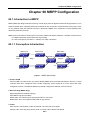
CHAPTER 60 MRPP CONFIGURATION .......................................................................60-1
60.1 INTRODUCTION TO MRPP ................................................................................................................ 60-1
60.1.1 Conception Introduction ...................................................................................................... 60-1
60.1.2 MRPP Protocol Packet Types ............................................................................................. 60-2
60.1.3 MRPP Protocol Operation System ...................................................................................... 60-3
60.2 MRPP CONFIGURATION TASK LIST .................................................................................................. 60-3
60.3 MRPP TYPICAL SCENARIO .............................................................................................................. 60-5
60.4 MRPP TROUBLESHOOTING .............................................................................................................. 60-7
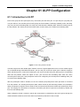
CHAPTER 61 ULPP CONFIGURATION ........................................................................61-1
61.1 INTRODUCTION TO ULPP ................................................................................................................. 61-1
61.2 ULPP CONFIGURATION TASK LIST ................................................................................................... 61-2
61.3 ULPP TYPICAL EXAMPLES .............................................................................................................. 61-4
61.3.1 ULPP Typical Example1 ...................................................................................................... 61-4
61.3.2 ULPP Typical Example2 ...................................................................................................... 61-6
61.4 ULPP TROUBLESHOOTING............................................................................................................... 61-7
CHAPTER 62 ULSM CONFIGURATION .......................................................................62-1
62.1 INTRODUCTION TO ULSM................................................................................................................. 62-1
62.2 ULSM CONFIGURATION TASK LIST................................................................................................... 62-2
62.3 ULSM TYPICAL EXAMPLE ................................................................................................................ 62-3
62.4 ULSM TROUBLESHOOTING .............................................................................................................. 62-4
CHAPTER 63 SNTP CONFIGURATION ........................................................................63-1
63.1 INTRODUCTION TO SNTP ................................................................................................................. 63-1
63.2 TYPICAL EXAMPLES OF SNTP CONFIGURATION ................................................................................ 63-2
CHAPTER 64 NTP FUNCTION CONFIGURATION .......................................................64-1
64.1 INTRODUCTION TO NTP FUNCTION ................................................................................................... 64-1
64.2 NTP FUNCTION CONFIGURATION TASK LIST ..................................................................................... 64-1
64.3 TYPICAL EXAMPLES OF NTP FUNCTION ............................................................................................ 64-4
64.4 NTP FUNCTION TROUBLESHOOTING ................................................................................................. 64-4
CHAPTER 65 DNSV4/V6 CONFIGURATION ................................................................65-1
65.1 INTRODUCTION TO DNS ................................................................................................................... 65-1
65.2 DNSV4/V6 CONFIGURATION TASK LIST ............................................................................................ 65-2
15
65.3 TYPICAL EXAMPLES OF DNS............................................................................................................ 65-4
65.4 DNS TROUBLESHOOTING................................................................................................................. 65-5
CHAPTER 66 MONITOR AND DEBUG .........................................................................66-1
66.1 PING ............................................................................................................................................... 66-1
66.2 PING6 ............................................................................................................................................. 66-1
66.3 TRACEROUTE .................................................................................................................................. 66-1
66.4 TRACEROUTE6 ................................................................................................................................ 66-1
66.5 SHOW ............................................................................................................................................. 66-2
66.6 DEBUG ............................................................................................................................................ 66-3
66.7 SYSTEM LOG ................................................................................................................................... 66-3
66.7.1 System Log Introduction ..................................................................................................... 66-3
66.7.2 System Log Configuration ................................................................................................... 66-5
66.7.3 System Log Configuration Example .................................................................................... 66-5
CHAPTER 67 RELOAD SWITCH AFTER SPECIFIED TIME ........................................67-1
67.1 INTRODUCE TO RELOAD SWITCH AFTER SPECIFID TIME ..................................................................... 67-1
67.2 RELOAD SWITCH AFTER SPECIFID TIME TASK LIST ............................................................................ 67-1
CHAPTER 68 DEBUGGING AND DIAGNOSIS FOR PACKETS RECEIVED AND SENT
BY CPU ..........................................................................................................................68-1
68.1 INTRODUCTION TO DEBUGGING AND DIAGNOSIS FOR PACKETS RECEIVED AND SENT BY CPU ............. 68-1
68.2 DEBUGGING AND DIAGNOSIS FOR PACKETS RECEIVED AND SENT BY CPU TASK LIST ........................ 68-1
CHAPTER 69 SWITCH OPERATION ............................................................................69-1
69.1 ADDRESS TABLE .............................................................................................................................. 69-1
69.2 LEARNING ....................................................................................................................................... 69-1
69.3 FORWARDING & FILTERING............................................................................................................... 69-1
69.4 STORE-AND-FORWARD .................................................................................................................... 69-1
69.5 AUTO-NEGOTIATION ......................................................................................................................... 69-2
CHAPTER 70 TROUBLE SHOOTING ...........................................................................70-1
CHAPTER 71 APPENDEX A .........................................................................................71-1
71.1 A.1 SWITCH'S RJ-45 PIN ASSIGNMENTS........................................................................................... 71-1
71.2 A.2 10/100MBPS, 10/100BASE-TX ................................................................................................. 71-1
CHAPTER 72 GLOSSARY.............................................................................................72-1
16
Chapter 1 INTRODUCTION
Chapter 1 INTRODUTION
The PLANET XGS3-24040 is 24-Port 10/100/1000Mbps with 4 shared 1000 SFP slots, and 4 optional 10G
slots IPv4/IPv6abit Layer 3 Managed Stackable Switch. It boasts a high performance switch architecture that
is capable of providing non-blocking switch fabric and wire-speed throughput as high as 88Gbps. Its two
optional 10Gbps XFP uplink slots also offer incredible extensibility, flexibility and connectivity to the Core
switch or Servers. Terms of “Managed Switch” means the Switches mentioned titled in the cover page of this
User’s manual.
1.1 Packet Contents
Open the box of the Managed Switch and carefully unpack it. The box should contain the following items:
Check the contents of your package for following parts:
XGS3-24040 Switch
X1
User's Manual
X1
Quick Installation Guide
X1
Power Cord
X1
RJ-45-to-DB9 Console Cable
X1
SFP Dust Caps
X4
Rubber Fee
X4
Two Rack-mounting Brackets with
X1
Attachment Screws
If any of these are missing or damaged, please contact your dealer immediately, if possible, retain the carton
including the original packing material, and use them against to repack the product in case there is a need to
return it to us for repair.
1.2 Product Description
Cost-effective IPv6/IPv4 Dual Stack Managed 10 Gigabit Switch solution for Enterprise and ISP
PLANET XGS3-24040 switch is 10Gb Ethernet routing switch. The XGS3-24040 has 24 fixed
10/100/1000Mbps ports with 4 shard 1000Base-SX/LX SFP slots, 2 10GbE XFP module slots and 2 10GbE
stack slots. The XGS3-24040 switch is based on 10GbE switching technology and fully supports IPv6,
whereas their height is only 1U. As distribution layer switches which are featured in high performance, small
size and flexibility, XGS3-24040 switch with advanced intelligent and secure features, can serve ideally as
distribution layer switches for campus networks, enterprise networks and IP metropolitan networks; as well as
core layer switches for small and medium-sized networks.
Support 10Gb Ethernet
10Gb Ethernet which adopts full-duplex technology instead of low-speed, half-duplex CSMA/CD protocol, is a
1-1
Chapter 1 INTRODUCTION
big leap in the evolution of Ethernet. 10Gb Ethernet can be deployed in star or ring topologies. With 10Gb
Ethernet, XGS3-24040 switch provide broad bandwidth and powerful processing capacity. It is suitable for
metropolitan networks and wide area networks. Using XGS3-24040 switch, users can simplify network
structures and reduce cost of network construction.
Networking Protocols
XGS3-24040 switch support 802.1d/w/s, 802.1Q, 802.1p, 802.3ad, 802.3x, GVRP, DHCP and SNTP etc. The
switches also support comprehensively the multicast protocols such as IGMP, DVMRP and PIM. Moreover,
XGS3-24040 switch support RIPv1/2, OSPF and IPv6. All these protocols supported enable XGS3-24040
switch to meet the requirements of complex network constructions.
Secure Power Supply
XGS3-24040 switch provide AC/DC power redundancy. XGS3-24040 can be deployed with 100~240V AC
power input, 12V DC power input or 100~240V AC power / 12V DC power input simultaneously.
ACL
XGS3-24040 series switch support comprehensively ACL policies. The traffic can be classified by
source/destination IP addresses, source/destination MAC addresses, IP protocols, TCP/UDP, IP precedence,
time ranges and ToS. And various policies can be conducted to forward the traffic. By implementing ACL
policies, users can filter the virus packets such as “Worm.Blaster”, “Worm.Sasser” and “Red Code” etc.
XGS3-24040 switch also support IEEE802.1x port based access authentication, which can be deployed with
RADIUS, to ensure the port level security and block illegal users.
QoS
XGS3-24040 switch fully support DiffServ Module. Users can specify a queue bandwidth on each port.
WRR/SP/SWRR scheduling is also supported. XGS3-24040 supports the port security. Users can deploy
trusted CoS, DSCP, IP precedence and port priority. User can also modify packets’ DSCP and COS values.
The traffic can be classified by port, VLAN, DSCP, IP precedence and ACL table. User can also modify
packets’ DSCP and IP precedence values. Users can specify different bandwidths for voice/data/video to
customize different qualities of service.
Perfect Web Management.
XGS3-24040 support SNMP, In-band and Out-of band Management, CLI and WEB interface and RMON. It
can mail the correlative sensitive information to the administrator abide by SMTP protocol. XGS3-24040
support SSH protocol, ensure the configuration management security of the switch.
1-2
Chapter 1 INTRODUCTION
1.3 Product Features
Physical Port
24-Port 10/100/1000Base-T RJ-45 copper
4 1000Base-SX/LX mini-GBIC/SFP slots, shared with Port-21 to Port-24.
2 10G XFP module slots, supports 10GBase-SR/LR XFP transceivers
2 10G Stack slots
1 RJ-45 serial console interface for Switch basic management and setup
IP Stacking
IP stacking technology, connect with stack member via both Gigabit TP/SFP interface or 10G Stack
slots
Single IP address management, supports up to 36 units stacking together.
Stacking architecture supports Chain and Ring mode
IP Routing Features
IP Routing protocol supports RIPv1/v2, OSPFv2, BGP4
Routing interface provides Per-Port routing and VLAN routing mode
VRRP protocol for redundant routing deploy
Supports route redistribution
Multicast Routing Features
Supports PIM-DM and PIM-SM(Protocol Independent Multicast - Dense Mode)and PIM-SM
(Protocol Independent Multicast - Sparse Mode)
Supports DVMRP(Distance Vector Multicast Routing Protocol)
Supports IGMPv1/v2/v3
Layer 2 Features
Complies with the IEEE 802.3, IEEE 802.3u, IEEE 802.3ab, IEEE 802.3z Gigabit Ethernet
standard
Supports Auto-negotiation and half duplex/full duplex modes for all 10Base-T/100Base-TX and
1000Base-T ports.
Auto-MDI/MDI-X detection for each RJ-45 port
Prevents packet loss with back pressure (Half-Duplex) and IEEE 802.3x PAUSE frame flow control
(Full-Duplex)
High performance of Store-and-Forward architecture, broadcast storm control and runt/CRC
filtering eliminates erroneous packets to optimize the network bandwidth
8K MAC address table, automatic source address learning and ageing
Support VLAN
− IEEE 802.1Q Tagged VLAN
− Up to 4K VLANs groups, out of 4041 VLAN IDs
− Provider Bridging (VLAN Q-in-Q) support (IEEE 802.1ad)
− GVRP protocol for VLAN Management
− Private VLAN Edge (PVE)
Support Spanning Tree Protocol
1-3
Chapter 1 INTRODUCTION
− STP, IEEE 802.1d (Spanning Tree Protocol)
− RSTP, IEEE 802.1w (Rapid Spanning Tree Protocol)
− MSTP, IEEE 802.1s (Multiple Spanning Tree Protocol, spanning tree by VLAN)
Support Link Aggregation
− 802.3ad Link Aggregation Control Protocol (LACP)
− Cisco ether-channel (Static Trunk)
− Maximum 8 trunk groups, up to 8 ports per trunk group
− Up to 16Gbps bandwidth(Duplex Mode)
Provide Port Mirror (many-to-1)
Port Mirroring to monitor the incoming or outgoing traffic on a particular port
Quality of Service
8 priority queues on all switch ports.
Supports for strict priority and weighted round robin (WRR) CoS policies
Ingress Shaper and Egress Rate Limit per port bandwidth control
Traffic-policing policies based on application
Multicast
Supports IGMP Snoopingv1, v2 and v3
Querier mode support
Security
IEEE 802.1x Port-Based network access authentication
MAC-Based network access authentication
IP-Based Access Control List (ACL)
MAC-Based Access Control List
Static MAC
Management
WEB-based, Telnet, Console Command Line management
SSH( Secure Shell), SSL
Accesses through SNMPv1, v2c and v3 security set and get requests.
Four groups (history, statistics, alarms, and events) of embedded remote monitoring (RMON)
agents for network monitoring and traffic analysis
Built-in Trivial File Transfer Protocol (TFTP) client
BOOTP and DHCP for IP address assignment
Firmware upload/download via HTTP / TFTP
SNTP (Simple Network Time Protocol)
LLDP Protocol
Redundant Power System
100~240V AC / 12V DC Dual power redundant
Active-active redundant power failure protection
Backup of catastrophic power failure on one supply
1-4
Chapter 1 INTRODUCTION
1.4 Product Specification
Product
XGS3-24040
Hardware Specification
Copper Ports
SFP/mini-GBIC Slots
Expansion Slots
24 10/ 100/1000Base-T RJ-45 Auto-MDI/MDI-X ports
4 SFP slots, 1000Base-SX/LX SFP transceiver compatible
Shared with Port-21 to Port-24
2 slots for PLANET XGS3-XFP, 1-Port 10G XFP optic module
Support module Hot-swappable
Stack Slots
2 slots for PLANET XGS3-TGS30, 10G stack cable
Switch Processing Scheme
Store-and-Forward
Switch Fabric
128Gbps
Throughput
95Mpps@64Bytes
Address Table
8K entries
Share data Buffer
0.75Mbytes
VLAN Table
4K
ACL Table
1K
Routing Table
512
Layer 3 Interface
500
Port Queues
8
Flow Control
Jumbo Frame
IEEE 802.3x Pause Frame for Full-Duplex
Back pressure for Half-Duplex
9Kbytes
System:
LED
Power, SYS diagnostic, Redundant Power, Module, Stack
Ports:
10/100/1000 Link/Act
Dimension (W x D x H)
440 x 415 x 44.5mm (W x D x H), 1U height
Weight
5.8kg
Power Requirement
Power Consumption
AC: 100~240V AC, 50/60Hz, Auto-sensing.
DC: 12V DC@ 13A
67 Watts
IPv4 Layer 3 functions
Static Route, RIPv1/v2, OSPFv2, BGP4
IP Routing Protocol
Policy-Based Routing (PBR)
LPM Routing (MD5 authentication)
Multicast Routing Protocol
IGMPv1 / 2 / 3, DVMRP, PIM-DM/SM, PIM-SSM
Layer 3 Protocol
VRRP, ARP, ARP Proxy
Routing Interface
Per VLAN
IPv6 Layer 3 functions
IP Routing Protocol
RIPng, OSPFv3, BGP4+
1-5
Chapter 1 INTRODUCTION
PIM-SM/DM for IPv6
MLD for IPv6
Multicast Routing Protocol
MLDv1/v2
MLD Snooping, 6 to 4 Tunnels
Multicast receive control
Illegal multicast source detect
Layer 3 Protocol
Configured Tunnels , ISATAP, CIDR
Layer 2 function
Port disable/enable.
Auto-negotiation 10/100/1000Mbps full and half duplex mode
Port configuration
selection.
Bandwidth control on each port
Port Loopback detect
802.1Q Tagged Based VLAN ,up to 4K VLAN groups
VLAN
Q-in-Q
GVRP
Private VLAN
STP, IEEE 802.1d (Spanning Tree Protocol)
RSTP, IEEE 802.1w (Rapid Spanning Tree Protocol)
Spanning Tree Protocol
MSTP, IEEE 802.1s (Multiple Spanning Tree Protocol, spanning tree
by VLAN)
Root Guard
BPDU Guard
Static Trunk
Link Aggregation
IEEE 802.3ad LACP
Support 8 groups of 8-Port trunk support
Traffic classification based, Strict priority and WRR
8-level priority for switching
QoS
- Port Number
- 802.1p priority
- DSCP/TOS field in IP Packet
Policy-based DiffServ
IGMPv1/v2/v3 Snooping
Multicast
IGMP Proxy
IGMP Querier mode support
MLDv1/v2, MLDv1/v2 Snooping
Support Standard and Expanded ACL
IP-Based ACL / MAC-Based ACL
Access Control List
Time-Based ACL
ACL Pool can be used for QoS classification
Up to 1K entries
Support MAC+ port binding
Security
IPv4/IPv6 + MAC+ port binding
IPv4/IPv6 + port binding
Support MAC filter
1-6
Chapter 1 INTRODUCTION
ARP Spoofing Prevention
ARP Scanning Prevention
IP Source Guard
Authentication
IEEE 802.1x Port-Based network access control
AAA Authentication: IPv4/IPv6 over RADIUS
RFC-1213 MIB-II
IF-MIB
RFC-1493 Bridge MIB
RFC-1643 Ethernet MIB
RFC-2863 Interface MIB
RFC-2665 Ether-Like MIB
RFC-2674 Extended Bridge MIB
SNMP MIBs
RFC-2819 RMON MIB (Group 1, 2, 3 and 9)
RFC-2737 Entity MIB
RFC-2618 RADIUS Client MIB
RFC-2933 IGMP-STD-MIB
RFC3411 SNMP-Frameworks-MIB
IEEE802.1X PAE
LLDP
MAU-MIB
Management Function
System Configuration
Console, Telnet, SSH, Web Browser, SSL, SNMPv1, v2c and v3
Support the unite for IPv4/IPv6 HTTP and SSL
Support the user IP security inspection for IPv4/IPv6 SNMP
Support MIB and TRAP
Support IPv4/IPv6 FTP/TFTP
Support IPv4/IPv6 NTP
Support RMOM 1, 2, 3, 9 four group
Support the RADIUS authentication for IPv4/IPv6 telnet user name
and password
Management
Support IPv4/IPv6 SSH
The right configuration for users can adopt radius server’s shell
management
Support the function for timing-reset bases needs
Support CLI, support Console(RS-232), support Telnet
Support SNMPv1/v2c/v3
Support Security IP safety net management function:avoid to
unlawful landing at nonrestrictive area.
Support TACACS+
Standards Conformance
Regulation Compliance
FCC Part 15 Class A, CE
IEEE 802.3 10Base-T
Standards Compliance
IEEE 802.3u 100Base-TX
IEEE 802.3z Gigabit SX/LX
IEEE 802.3ab Gigabit 1000T
1-7
Chapter 1 INTRODUCTION
IEEE 802.3ae 10 Gigabit Ethernet
IEEE 802.3x Flow Control and Back pressure
IEEE 802.3ad Port trunk with LACP
IEEE 802.1d Spanning tree protocol
IEEE 802.1w Rapid spanning tree protocol
IEEE 802.1s Multiple spanning tree protocol
IEEE 802.1p Class of service
IEEE 802.1Q VLAN Tagging
IEEE 802.1x Port Authentication Network Control
IEEE 802.1ab LLDP
1-8
XGS3 Configuration Guide
Chapter 2 INSTALLATION
This section describes the hardware features and installation of the Managed Switch on the desktop or rack
mount. For easier management and control of the Managed Switch, familiarize yourself with its display
indicators, and ports. Front panel illustrations in this chapter display the unit LED indicators. Before
connecting any network device to the Managed Switch, please read this chapter completely.
2.1 Hardware Description
2.1.1 Switch Front Panel
The unit front panel provides a simple interface monitoring the switch. Figure 2-1-1 shows the front panel of
the Managed Switches.
XGS3-24040 Front Panel
Figure 2-1-1 XGS3-24040 front panel
■ Gigabit TP interface
10/100/1000Base-T Copper, RJ-45 Twist-Pair: Up to 100 meters.
■ Gigabit SFP slots
1000Base-SX/LX mini-GBIC slot, SFP (Small Factor Pluggable) transceiver module: From 550 meters
(Multi-mode fiber), up to 10/30/50/70/120 kilometers (Single-mode fiber).
■ Console Port
The console port is a RJ-45 type, RS-232 male seria port connector. It is an interface for connecting a
terminal directly. Through the console port, it provides rich diagnostic information includes IP Address
setting, factory reset, port management, link status and system setting. Users can use the attached
RS-232 cable in the package and connect to the console port on the device. After the connection, users
an run any terminal emulation program (Hyper Terminal, ProComm Plus, Telix, Winterm and so on) to
enter the statup screen of the device.
2.1.2 LED Indications
The front panel LEDs indicates instant status of port links, data activity, system operation, Stack status and
system power, helps monitor and troubleshoot when needed.
2-1
XGS3 Configuration Guide
XGS3-24040 LED indication
Figure 2-1-2 XGS3-24040 LED panel
■ System
LED
Color
Green
PWR
Orange
Off
Green
RPS
Orange
Off
SYS
Green
Orange
Green
Stack
Orange
Off
Module
Green
Off
Function
Lights to indicate that the Switch has power.
Power is malfunctioning.
Power is off.
Redundancy power unit is charging
Redundancy power unit is malfunctioning
Redundancy power unit is off
Lights to indicate the system automatic diagnoses is completed
Blink to indicate the system automatic diagnoses is under way
Lights to indicate the system automatic diagnose is malfunctioning
Lights to indicate the 10G Uplink and downlink is operating normally
Blink to indicate 10G Uplink is malfunctioning
Downlink is malfunctioning
No stack link
Lights to indicate the extended XFP module is installed
Blink to indicate the installed extended module is disabled
No extended module
■ 10/100/1000Base-T and SFP interfaces
LED
Color
Function
Lights: To indicate the link through that port is successfully established
with speed 1000Mbps
Green
Blink: To indicate that the switch is actively sending or receiving data
over that port.
Lights: To indicate the link through that port is successfully established
LNK/ACT
Orange
with speed 100Mbps or 10Mbps
Blink: To indicate that the switch is actively sending or receiving data
over that port.
Off
No flow go through the port
2-2
XGS3 Configuration Guide
2.1.3 Switch Rear Panel
The rear panel of the Managed Switch indicates an AC inlet power socket, which accept input power from 100
to 240V AC, 50-60Hz. Figure 2-1-3 shows the rear panel of these Managed Switches
XGS3-24040 Rear Panel
Figure 2-1-3 Rear panel of XGS3-24040
■ AC Power Receptacle
For compatibility with electric service in most areas of the world, the Managed Switch’s power supply
automatically adjusts to line power in the range 100-240VAC and 50/60 Hz.
Plug the female end of the power cord firmly into the receptalbe on the rear panel of the Managed Switch.
Plug the other end of the power cord into an electric service outlet then the power will be ready.
The device is a power-required device, it means, it will not work till it is powered. If your
networks should active all the time, please consider using UPS (Uninterrupted Power
Supply) for your device. It will prevent you from network data loss or network downtime.
Power Notice:
In some area, installing a surge suppression device may also help to protect your Managed
Switch from being damaged by unregulated surge or current to the Switch or the power
adapter.
2-3
XGS3 Configuration Guide
2.2 Install the Switch
This section describes how to install your Managed Switch and make connections to the Managed Switch.
Please read the following topics and perform the procedures in the order being presented. To install your
Managed Switch on a desktop or shelf, simply complete the following steps.
2.2.1 Desktop Installation
To install the Managed Switch on desktop or shelf, please follows these steps:
Step1: Attach the rubber feet to the recessed areas on the bottom of the Managed Switch.
Step2: Place the Managed Switch on the desktop or the shelf near an AC power source, as shown in Figure
2-2-1.
Figure 2-2-1 Place the Managed Switch on the desktop
Step3: Keep enough ventilation space between the Managed Switch and the surrounding objects.
When choosing a location, please keep in mind the environmental restrictions discussed in
Chapter 1, Section 4, and Specification.
Step4: Connect the Managed Switch to network devices.
Connect one end of a standard network cable to the 10/100/1000 RJ-45 ports on the front of the
Managed Switch
Connect the other end of the cable to the network devices such as printer servers, workstations or
routers…etc.
Connection to the Managed Switch requires UTP Category 5 network cabling with RJ-45
tips. For more information, please see the Cabling Specification in Appendix A.
2-4
XGS3 Configuration Guide
Step5: Supply power to the Managed Switch.
Connect one end of the power cable to the Managed Switch.
Connect the power plug of the power cable to a standard wall outlet.
When the Managed Switch receives power, the Power LED should remain solid Green.
2.2.2 Rack Mounting
To install the Managed Switch in a 19-inch standard rack, please follows the instructions described below.
Step1: Place the Managed Switch on a hard flat surface, with the front panel positioned towards the front
side.
Step2: Attach the rack-mount bracket to each side of the Managed Switch with supplied screws attached to
the package.
Figure 2-2-2 shows how to attach brackets to one side of the Managed Switch.
Figure 2-2-2 Attach brackets to the Managed Switch.
You must use the screws supplied with the mounting brackets. Damage caused to the
parts by using incorrect screws would invalidate the warranty.
Step3: Secure the brackets tightly.
Step4: Follow the same steps to attach the second bracket to the opposite side.
Step5: After the brackets are attached to the Managed Switch, use suitable screws to securely attach the
brackets to the rack, as shown in Figure 2-2-3.
2-5
XGS3 Configuration Guide
Figure 2-2-3 Mounting XGS3-24040 in a Rack
Step6: Proceeds with the steps 4 and steps 5 of session 2.2.1 Desktop Installation to connect the network
cabling and supply power to the Managed Switch.
2.2.3 Installing the SFP transceiver
The sections describe how to insert an SFP transceiver into an SFP slot.
The SFP transceivers are hot-pluggable and hot-swappable. You can plug-in and out the transceiver to/from
any SFP port without having to power down the Managed Switch. As the Figure 2-2-4 appears.
Figure 2-2-4 Plug-in the SFP transceiver
2-6
XGS3 Configuration Guide
Approved PLANET SFP Transceivers
PLANET Managed Switch supports both Single mode and Multi-mode SFP transceiver. The following list of
approved PLANET SFP transceivers is correct at the time of publication:
Gigabit SFP Transceiver modules:
■ MGB-SX SFP (1000BASE-SX SFP transceiver / Multi-mode / 850nm / 220m~550m)
■ MGB-LX SFP (1000BASE-LX SFP transceiver / Single-mode / 1310nm / 10km)
■ MGB-L30 SFP (1000BASE-LX SFP transceiver / Single-mode / 1310nm / 30km)
■ MGB-L50 SFP (1000BASE-LX SFP transceiver / Single-mode / 1310nm / 50km)
■ MGB-LA10 SFP (1000BASE-LX SFP transceiver / WDM Single-mode / TX: 1310nm, RX: 1550nm/
10km)
■ MGB-LB10 SFP (1000BASE-LX SFP transceiver / WDM Single-mode / TX: 1550nm, RX: 1310nm /
10km)
It recommends using PLANET SFPs on the Managed Switch. If you insert a SFP
transceiver that is not supported, the Managed Switch will not recognize it.
Before connect the other Managed Switches, workstation or Media Converter.
1.
Make sure both side of the SFP transceiver are with the same media type, for example: 1000Base-SX
to 1000Base-SX, 1000Bas-LX to 1000Base-LX.
2.
Check the fiber-optic cable type match the SFP transceiver model.
To connect to 1000Base-SX SFP transceiver, use the Multi-mode fiber cable-with one side must be
male duplex LC connector type.
To connect to 1000Base-LX SFP transceiver, use the Single-mode fiber cable-with one side must
be male duplex LC connector type.
Connect the fiber cable
1.
Attach the duplex LC connector on the network cable into the SFP transceiver.
2.
Connect the other end of the cable to a device – switches with SFP installed, fiber NIC on a workstation
or a Media Converter.
3.
Check the LNK/ACT LED of the SFP slot on the front of the Managed Switch. Ensure that the SFP
transceiver is operating correctly.
4.
Check the Link mode of the SFP port if the link failed. Co works with some fiber-NICs or Media
Converters, set the Link mode to “1000 Force” is needed.
Remove the transceiver module
1.
Make sure there is no network activity by consult or check with the network administrator. Or through the
management interface of the switch/converter (if available) to disable the port in advance.
2.
Remove the Fiber Optic Cable gently.
3.
Turn the handle of the MGB module to horizontal.
4.
Pull out the module gently through the handle.
2-7
XGS3 Configuration Guide
Figure 2-22 Pull out the SFP transceiver
Never pull out the module without pull the handle or the push bolts on the module.
Direct pull out the module with violent could damage the module and SFP module
slot of the Managed Switch.
2-8
XGS3 Configuration Guide
Chapter 3 Switch Management
3.1 Management Options
After purchasing the switch, the user needs to configure the switch for network management. Switch provides
two management options: in-band management and out-of-band management.
3.1.1 Out-Of-Band Management
Out-of-band management is the management through Console interface. Generally, the user will use
out-of-band management for the initial switch configuration, or when in-band management is not available.
For instance, the user must assign an IP address to the switch via the Console interface to be able to access
the switch through Telnet.
The procedures for managing the switch via Console interface are listed below:
Step 1: Setting up the environment:
Figure 3-1 Out-of-band Management Configuration Environment
As shown in above, the serial port (RS-232) is connected to the switch with the serial cable provided. The
table below lists all the devices used in the connection.
Device Name
Description
PC machine
Has functional keyboard and RS-232, with terminal emulator
installed, such as HyperTerminal included in Windows
9x/NT/2000/XP.
Serial port cable
One end attach to the RS-232 serial port, the other end to the
Console port.
Switch
Functional Console port required.
Step 2: Entering the HyperTerminal
Open the HyperTerminal included in Windows after the connection established. The example below is based
on the HyperTerminal included in Windows XP.
1) Click Start menu - All Programs -Accessories -Communication - HyperTerminal.
3-9
XGS3 Configuration Guide
Figure 3-2 Opening Hyper Terminal
2) Type a name for opening HyperTerminal, such as “Switch”.
Figure 3-3 Opening HyperTerminal
3) In the “Connecting using” drop-list, select the RS-232 serial port used by the PC, e.g. COM1, and click
“OK”.
3-10
XGS3 Configuration Guide
Figure 3-4 Opening HyperTerminal
4) COM1 property appears, select “9600” for “Baud rate”, “8” for “Data bits”, “none” for “Parity checksum”, “1”
for stop bit and “none” for traffic control; or, you can also click “Restore default” and click “OK”.
Figure 3-5 Opening HyperTerminal
Step 3:
Entering switch CLI interface
Power on the switch, the following appears in the HyperTerminal windows, that is the CLI configuration mode
for Switch.
3-11
XGS3 Configuration Guide
Testing RAM...
0x077C0000 RAM OK
Loading MiniBootROM...
Attaching to file system ...
Loading nos.img ...
done.
Booting......
Starting at 0x10000...
Attaching to file system ...
……
--- Performing Power-On Self Tests (POST) --DRAM Test....................PASS!
PCI Device 1 Test............PASS!
FLASH Test...................PASS!
FAN Test.....................PASS!
Done All Pass.
------------------ DONE --------------------Current time is SUN JAN 01 00:00:00 2006
……
Switch>
The user can now enter commands to manage the switch. For a detailed description for the commands,
please refer to the following chapters.
3.1.2 In-band Management
In-band management refers to the management by login to the switch using Telnet, or using HTTP, or using
SNMP management software to configure the switch. In-band management enables management of the
switch for some devices attached to the switch. In the case when in-band management fails due to switch
configuration changes, out-of-band management can be used for configuring and managing the switch.
3.1.2.1 Management via Telnet
To manage the switch with Telnet, the following conditions should be met:
1) Switch has an IPv4/IPv6 address configured;
2) The host IP address (Telnet client) and the switch’s VLAN interface IPv4/IPv6 address is in the same
network segment;
3) If 2) is not met, Telnet client can connect to an IPv4/IPv6 address of the switch via other devices,
such as a router.
The switch is Layer 3 switch that can be configured with several IPv4/IPv6 addresses. The following example
assumes the shipment status of the switch where only VLAN1 exists in the system. The following describes
the steps for a Telnet client to connect to the switch’s VLAN1 interface by Telnet (with IPv4 address example):
3-12
XGS3 Configuration Guide
Figure 3-6 Manage the switch by Telnet
Step 1: Configure the IP addresses for the switch and start the Telnet Server function on the switch.
First is the configuration of host IP address. This should be within the same network segment as the switch
VLAN1 interface IP address. Suppose the switch VLAN1 interface IP address is 10.1.128.251/24. Then, a
possible host IP address is 10.1.128.252/24. Run “ping 10.1.128.251” from the host and verify the result,
check for reasons if ping failed.
The IP address configuration commands for VLAN1 interface are listed below. Before in-band management,
the switch must be configured with an IP address by out-of-band management (i.e. Console mode), the
configuration commands are as follows (All switch configuration prompts are assumed to be “Switch”
hereafter if not otherwise specified):
Switch>
Switch>enable
Switch#config
Switch(config)#interface vlan 1
Switch(Config-if-Vlan1)#ip address 10.1.128.251 255.255.255.0
Switch(Config-if-Vlan1)#no shutdown
To enable the Telnet Server function, users should type the CLI command telnet-server enable in the global
mode as below:
Switch>en
Switch#config
Switch(config)# telnet-server enable
Step 2: Run Telnet Client program.
Run Telnet client program included in Windows with the specified Telnet target.
3-13
XGS3 Configuration Guide
Figure 3-7 Run telnet client program included in Windows
Step 3: Login to the switch.
Login to the Telnet configuration interface. Valid login name and password are required, otherwise the switch
will reject Telnet access. This is a method to protect the switch from unauthorized access. As a result, when
Telnet is enabled for configuring and managing the switch, username and password for authorized Telnet
users must be configured with the following command:
username <username> privilege <privilege> [password (0|7) <password>].
To open the local authentication style with the following command: authentication line vty login local. Privilege
option must exist and just is 15. Assume an authorized user in the switch has a username of “test”, and
password of “test”, the configuration procedure should like the following:
Switch>enable
Switch#config
Switch(config)#username test privilege 15 password 0 test
Switch(config)#authentication line vty login local
Enter valid login name and password in the Telnet configuration interface, Telnet user will be able to enter the
switch’s CLI configuration interface. The commands used in the Telnet CLI interface after login is the same as
that in the Console interface.
3-14
XGS3 Configuration Guide
Figure 3-8 Telnet Configuration Interface
3.1.2.2 Management via HTTP
To manage the switch via HTTP, the following conditions should be met:
1)
Switch has an IPv4/IPv6 address configured;
2)
The host IPv4/IPv6 address (HTTP client) and the switch’s VLAN interface IPv4/IPv6 address are in
the same network segment;
3)
If 2) is not met, HTTP client should connect to an IPv4/IPv6 address of the switch via other devices,
such as a router.
Similar to management the switch via Telnet, as soon as the host succeeds to ping/ping6 an IPv4/IPv6
address of the switch and to type the right login password, it can access the switch via HTTP. The
configuration list is as below:
Step 1: Configure the IP addresses for the switch and start the HTTP server function on the switch.
For configuring the IP address on the switch through out-of-band management, see the telnet management
chapter.
To enable the WEB configuration, users should type the CLI command IP http server in the global mode as
below:
Switch>enable
Switch#config
Switch(config)#ip http server
3-15
XGS3 Configuration Guide
Step 2: Run HTTP protocol on the host.
Open the Web browser on the host and type the IP address of the switch, or run directly the HTTP protocol on
the Windows. For example, the IP address of the switch is “10.1.128.251”;
Figure 3-9 Run HTTP Protocol
When accessing a switch with IPv6 address, it is recommended to use the Firefox browser with 1.5 or later
version. For example, if the IPv6 address of the switch is 3ffe:506:1:2::3. Input the IPv6 address of the switch
is http://[3ffe:506:1:2::3] and the address should draw together with the square brackets.
Step 3:
Login to the switch.
Login to the Web configuration interface. Valid login name and password are required, otherwise the switch
will reject HTTP access. This is a method to protect the switch from unauthorized access. As a result, when
Telnet is enabled for configuring and managing the switch, username and password for authorized Telnet
users must be configured with the following command:
username <username> privilege <privilege> [password (0|7) <password>]
To open the local authentication style with the following command: authentication line web login local.
Privilege option must exist and just is 15. Assume an authorized user in the switch has a username of
“admin”, and password of “admin”, the configuration procedure should like the following:
Switch>enable
Switch#config
Switch(config)#username admin privilege 15 password 0 admin
Switch(config)#authentication line web login local
3-16
XGS3 Configuration Guide
The Web login interface of XGS3-24040 is as below:
Figure 3-10 Web Login Interface
Input the right username and password, and then the main Web configuration interface is shown as below.
Figure 1-11 Main Web Configuration Interface
When configure the switch, the name of the switch is composed with English letters.
3-17
XGS3 Configuration Guide
3.1.2.3 Manage the Switch via SNMP Network Management Software
The necessities required by SNMP network management software to manage switches:
1) IP addresses are configured on the switch;
2) The IP address of the client host and that of the VLAN interface on the switch it subordinates to
should be in the same segment;
3) If 2) is not met, the client should be able to reach an IP address of the switch through devices like
routers;
4) SNMP should be enabled.
The host with SNMP network management software should be able to ping the IP address of the switch, so
that, when running, SNMP network management software will be able to find it and implement read/write
operation on it. Details about how to manage switches via SNMP network management software will not be
covered in this manual, please refer to “Snmp network management software user manual”.
3.2 CLI Interface
The switch provides thress management interface for users: CLI (Command Line Interface) interface, Web
interface, Snmp netword management software. We will introduce the CLI interface and Web configuration
interface in details, Web interface is familiar with CLI interface function and will not be covered, please refer to
“Snmp network management software user manual”.
CLI interface is familiar to most users. As aforementioned, out-of-band management and Telnet login are all
performed through CLI interface to manage the switch.
CLI Interface is supported by Shell program, which consists of a set of configuration commands. Those
commands are categorized according to their functions in switch configuration and management. Each
category represents a different configuration mode. The Shell for the switch is described below:
Configuration Modes
Configuration Syntax
Shortcut keys
Help function
Input verification
Fuzzy match support
3-18
XGS3 Configuration Guide
3.2.1 Configuration Modes
Figure 3-12 Shell Configuration Modes
3.2.1.1 User Mode
On entering the CLI interface, entering user entry system first. If as common user, it is defaulted to User Mode.
The prompt shown is “Switch>“, the symbol “>“ is the prompt for User Mode. When exit command is run
under Admin Mode, it will also return to the User Mode.
Under User Mode, no configuration to the switch is allowed, only clock time and version information of the
switch can be queries.
3.2.1.2 Admin Mode
To Admin Mode sees the following: In user entry system, if as Admin user, it is defaulted to Admin Mode.
Admin Mode prompt “Switch#” can be entered under the User Mode by running the enable command and
entering corresponding access levels admin user password, if a password has been set. Or, when exit
command is run under Global Mode, it will also return to the Admin Mode. Switch also provides a shortcut key
sequence "Ctrl+z”, this allows an easy way to exit to Admin Mode from any configuration mode (except User
Mode).
Under Admin Mode, the user can query the switch configuration information, connection status and traffic
statistics of all ports; and the user can further enter the Global Mode from Admin Mode to modify all
configurations of the switch. For this reason, a password must be set for entering Admin mode to prevent
unauthorized access and malicious modification to the switch.
3-19
XGS3 Configuration Guide
3.2.1.3 Global Mode
Type the config command under Admin Mode will enter the Global Mode prompt “Switch(config)#”. Use the
exit command under other configuration modes such as Port Mode, VLAN mode will return to Global Mode.
The user can perform global configuration settings under Global Mode, such as MAC Table, Port Mirroring,
VLAN creation, IGMP Snooping start and STP, etc. And the user can go further to Port Mode for configuration
of all the interfaces.
Interface Mod
Use the interface command under Global Mode can enter the interface mode specified. Switch provides three
interface type: 1. VLAN interface; 2. Ethernet port; 3. port-channel, accordingly the three interface
configuration modes.
Interface Type
Entry
Operates
VLAN Interface
Type interface vlan <Vlan-id>
Configure switch IPs, etc
command under Global Mode.
Exit
Use the exit command
to return to Global
Mode.
Ethernet Port
port-channel
Type interface ethernet
Configure supported
Use the exit command
<interface-list> command
duplex mode, speed, etc.
to return to Global
under Global Mode.
of Ethernet Port.
Mode.
Type interface port-channel
Configure port-channel
Use the exit command
<port-channel-number>
related settings such as
to return to Global
command under Global Mode.
duplex mode, speed, etc.
Mode.
VLAN Mode
Using the vlan <vlan-id> command under Global Mode can enter the corresponding VLAN Mode. Under
VLAN Mode the user can configure all member ports of the corresponding VLAN. Run the exit command
to exit the VLAN Mode to Global Mode.
DHCP Address Pool Mode
Type the ip dhcp pool <name> command under Global Mode will enter the DHCP Address Pool Mode
prompt “Switch(Config-<name>-dhcp)#”. DHCP address pool properties can be configured under DHCP
Address Pool Mode. Run the exit command to exit the DHCP Address Pool Mode to Global Mode.
Route Mode
Routing Protocol
Entry
Operates
Exit
RIP Routing
Type router rip command
Configure RIP
Use the exit
Protocol
under Global Mode.
protocol parameters.
command to return
to Global Mode.
OSPF Routing
Type router ospf command
Configure OSPF
Use the exit
Protocol
under Global Mode.
protocol parameters.
command to return
to Global Mode.
BGP Routing
Type router bgp <AS
Configure BGP
Use the exit
Protocol
mumber> command under
protocol parameters.
command to return
Global Mode.
to Global Mode.
3-20
XGS3 Configuration Guide
ACL Mode
ACL type
Entry
Operates
Exit
Standard IP ACL
Type ip access-list
Configure parameters
Use the exit
Mode
standard command under
for Standard IP ACL
command to return
Global Mode.
Mode.
to Global Mode.
Type ip access-list
Configure parameters
Use the exit
extanded command under
for Extended IP ACL
command to return
Global Mode.
Mode.
to Global Mode.
Extended IP
ACL
Mode
3.2.2 Configuration Syntax
Switch provides various configuration commands. Although all the commands are different, they all abide by
the syntax for Switch configuration commands. The general commands format of Switch is shown below:
cmdtxt <variable> {enum1 | … | enumN } [option1 | … | optionN]
Conventions: cmdtxt in bold font indicates a command keyword; <variable> indicates a variable
parameter;{enum1 | … | enumN } indicates a mandatory parameter that should be selected from the
parameter set enum1~enumN; and the square bracket ([ ]) in [option1 | … | optionN] indicate an optional
parameter. There may be combinations of “< >“, “{ }” and “[ ]” in the command line, such as [<variable>],
{enum1 <variable>| enum2}, [option1 [option2]], etc.
Here are examples for some actual configuration commands:
show version, no parameters required. This is a command with only a keyword and no parameter, just
type in the command to run.
vlan <vlan-id>, parameter values are required after the keyword.
firewall {enable | disable}, user can enter firewall enable or firewall disable for this command.
snmp-server community {ro | rw} <string>, the followings are possible:
snmp-server community ro <string>
snmp-server community rw <string>
3.2.3 Shortcut Key Support
Switch provides several shortcut keys to facilitate user configuration, such as up, down, left, right and Blank
Space. If the terminal does not recognize Up and Down keys, ctrl +p and ctrl +n can be used instead.
Key(s)
Function
Back Space
Delete a character before the cursor, and the cursor moves back.
Up “↑”
Show previous command entered. Up to ten recently entered
commands can be shown.
Down “↓”
Show next command entered. When use the Up key to get previously
3-21
XGS3 Configuration Guide
entered commands, you can use the Down key to return to the next
command
Left “←”
Right “→”
The cursor moves one character to
You can use the Left and
the left.
Right key to modify an
The cursor moves one character to
entered command.
the right.
Ctrl +p
The same as Up key “↑”.
Ctrl +n
The same as Down key “↓”.
Ctrl +b
The same as Left key “←”.
Ctrl +f
The same as Right key “→”.
Ctrl +z
Return to the Admin Mode directly from the other configuration modes
(except User Mode).
Ctrl +c
Break the ongoing command process, such as ping or other command
execution.
Tab
When a string for a command or keyword is entered, the Tab can be
used to complete the command or keyword if there is no conflict.
3.2.4 Help Function
There are two ways in Switch for the user to access help information: the “help” command and the “?”.
Access to Help
Usage and function
Help
Under any command line prompt, type in “help” and press Enter will get a
brief description of the associated help system.
“?”
1. Under any command line prompt, enter “?” to get a command list of
the current mode and related brief description.
2. Enter a “?” after the command keyword with a embedded space. If the
position should be a parameter, a description of that parameter type,
scope, etc, will be returned; if the position should be a keyword, then a
set of keywords with brief description will be returned; if the output is
“<cr>“, then the command is complete, press Enter to run the
command.
3. A “?” immediately following a string. This will display all the commands
that begin with that string.
3.2.5 Input Verification
3.2.5.1 Returned Information: success
All commands entered through keyboards undergo syntax check by the Shell. Nothing will be returned if the
user entered a correct command under corresponding modes and the execution is successful.
Returned Information: error
3-22
XGS3 Configuration Guide
Output error message
Explanation
Unrecognized command or illegal
The entered command does not exist, or there is
parameter!
error in parameter scope, type or format.
Ambiguous command
At least two interpretations is possible basing on
the current input.
Invalid command or parameter
The command is recognized, but no valid
parameter record is found.
This command is not exist in
The command is recognized, but this command
current mode
can not be used under current mode.
Please configure precursor
The command is recognized, but the prerequisite
command "*" at first!
command has not been configured.
syntax error : missing '"' before the
Quotation marks are not used in pairs.
end of command line!
3.2.6 Fuzzy Match Support
Switch shell support fuzzy match in searching command and keyword. Shell will recognize commands or
keywords correctly if the entered string causes no conflict.
For example:
1) For command “show interfaces status ethernet1/1”, typing “sh in status ethernet1/1” will work.
2) However, for command “show running-config”, the system will report a “> Ambiguous command!”
error if only “show r” is entered, as Shell is unable to tell whether it is “show run” or “show
running-config”. Therefore, Shell will only recognize the command if “sh ru” is entered.
3-23
Chapter 4
Basic Switch Configuration
Chapter 4 Basic Switch Configuration
4.1 Basic Configuration
Basic switch configuration includes commands for entering and exiting the admin mode, commands for
entering and exiting interface mode, for configuring and displaying the switch clock, for displaying the version
information of the switch system, etc.
Command
Explanation
Normal User Mode/ Admin Mode
enable
disable
The User uses enable command to step into admin
mode from normal user mode. The disable command
is for exiting admin mode.
Admin Mode
config [terminal]
Enter global mode from admin mode.
Various Modes
Exit current mode and enter previous mode, such as
exit
using this command in global mode to go back to
admin mode, and back to normal user mode from
admin mode.
Except User Mode/ Admin Mode
end
Quit current mode and return to Admin mode when not
at User Mode/ Admin Mode.
Admin Mode
clock set <HH:MM:SS>
[YYYY.MM.DD]
Set system date and time.
show version
Display version information of the switch.
set default
Restore to the factory default.
write
reload
Save current configuration parameters to Flash
Memory.
Hot reset the switch.
4-1
Chapter 4
Basic Switch Configuration
4.2 Telnet Management
4.2.1 Telnet
4.2.1.1 Introduction to Telnet
Telnet is a simple remote terminal protocol for remote login. Using Telnet, the user can login to a remote host
with its IP address of hostname from his own workstation. Telnet can send the user’s keystrokes to the remote
host and send the remote host output to the user’s screen through TCP connection. This is a transparent
service, as to the user, the keyboard and monitor seems to be connected to the remote host directly.
Telnet employs the Client-Server mode, the local system is the Telnet client and the remote host is the Telnet
server. Switch can be either the Telnet Server or the Telnet client.
When switch is used as the Telnet server, the user can use the Telnet client program included in Windows or
the other operation systems to login to switch, as described earlier in the In-band management section. As a
Telnet server, switch allows up to 5 telnet client TCP connections.
And as Telnet client, using telnet command under Admin Mode allows the user to login to the other remote
hosts. Switch can only establish TCP connection to one remote host. If a connection to another remote host is
desired, the current TCP connection must be dropped.
4.2.1.2 Telnet Configuration Task List
1. Configuring Telnet Server
2. Telnet to a remote host from the switch.
1. Configuration of Telnet Server
Command
Explanation
Global Mode
telnet-server enable
no telnet-server enable
Enable the Telnet server function in the switch: the
“no telnet-server enable” command disables the
Telnet function.
username <user-name> [privilege
Configure user name and password of the telnet.
<privilege>] [password {0 | 7} <password>]
The no form command deletes the telnet user
no username <username>
authorization.
authentication securityip <ip-addr>
no authentication securityip <ip-addr>
authentication securityipv6 <ipv6-addr>
no authentication securityipv6 <ipv6-addr>
Configure the secure IP address to login to the
switch through Telnet: the no command deletes
the authorized Telnet secure address.
Configure the secure IPv6 address to login to the
switch through Telnet: the no command deletes
the authorized Telnet secure address.
authentication ip access-class
Binding standard IP ACL protocol to login with
{<num-std>|<name>}
Telnet/SSH/Web; the no form command will
4-2
Chapter 4
Basic Switch Configuration
no authentication ip access-class
cancel the binding ACL.
authentication ipv6 access-class
Binding standard IPv6 ACL protocol to login with
{<num-std>|<name>}
Telnet/SSH/Web; the no form command will
no authentication ipv6 access-class
cancel the binding ACL.
authentication line {console | vty | web} login
{local | radius | tacacs }
Configure telnet authentication mode.
no authentication line {console | vty | web}
login
Admin Mode
Display debug information for Telnet client login to
terminal monitor
the switch; the no command disables the debug
terminal no monitor
information.
2. Telnet to a remote host from the switch
Command
Explanation
Admin Mode
telnet {<ip-addr> | <ipv6-addr>
| host
Login to a remote host with the Telnet client
<hostname>} [<port>]
included in the switch.
4.2.2 SSH
4.2.2.1 Introduction to SSH
SSH (Secure Shell) is a protocol which ensures a secure remote access connection to network devices. It is
based on the reliable TCP/IP protocol. By conducting the mechanism such as key distribution, authentication
and encryption between SSH server and SSH client, a secure connection is established. The information
transferred on this connection is protected from being intercepted and decrypted. The switch meets the
requirements of SSH2.0. It supports SSH2.0 client software such as SSH Secure Client and putty. Users can
run the above software to manage the switch remotely.
The switch presently supports RSA authentication, 3DES cryptography protocol and SSH user password
authentication etc.
4-3
Chapter 4
Basic Switch Configuration
4.2.2.2 SSH Server Configuration Task List
SSH Server Configuration
Command
Explanation
Global Mode
ssh-server enable
no ssh-server enable
ssh-user <user-name> password {0 | 7}
<password>
no ssh-user <user-name>
ssh-server timeout <timeout>
no ssh-server timeout
Enable SSH function on the switch; the “no
ssh-server enable” command disables SSH
function.
Configure the username and password of SSH
client software for logging on the switch; the “no
ssh-user <user-name>” command deletes the
username.
Configure timeout value for SSH authentication;
the “no ssh-server timeout” command restores
the default timeout value for SSH authentication.
Configure the number of times for retrying SSH
ssh-server authentication-retires
authentication; the “no ssh-server
<authentication-retires>
authentication-retries” command restores the
no ssh-server authentication-retries
default number of times for retrying SSH
authentication.
ssh-server host-key create rsa modulus
Generate the new RSA host key on the SSH
<moduls>
server.
Admin Mode
Display SSH debug information on the SSH client
terminal monitor
side; the “no terminal monitor” command stops
terminal no monitor
displaying SSH debug information on the SSH
client side.
4.2.2.3 Typical SSH Server Configuration
Example1:
Requirement: Enable SSH server on the switch, and run SSH2.0 client software such as Secure shell client or
putty on the terminal. Log on the switch by using the username and password from the client.
Configure the IP address, add SSH user and enable SSH service on the switch. SSH2.0 client can log on the
switch by using the username and password to configure the switch.
Switch(config)#ssh-server enable
Switch(config)#interface vlan 1
Switch(Config-if-Vlan1)#ip address 100.100.100.200 255.255.255.0
Switch(Config-if-Vlan1)#exit
Switch(config)#ssh-user test password 0 test
4-4
Chapter 4
Basic Switch Configuration
In IPv6 networks, the terminal should run IPv6-supporing SSH client software, such as putty6. Users should
make no modification to configurations on the switch except allocating an IPv6 address for the local host.
4.3 Configurate Switch IP Addresses
All Ethernet ports of switch are default to Data Link layer ports and perform layer 2 forwarding. VLAN interface
represent a Layer 3 interface function which can be assigned an IP address, which is also the IP address of
the switch. All VLAN interface related configuration commands can be configured under VLAN Mode. Switch
provides three IP address configuration methods:
Manual
BOOTP
DHCP
Manual configuration of IP address is assign an IP address manually for the switch.
In BOOTP/DHCP mode, the switch operates as a BOOTP/DHCP client, send broadcast packets of
BOOTPRequest to the BOOTP/DHCP servers, and the BOOTP/DHCP servers assign the address on
receiving the request. In addition, switch can act as a DHCP server, and dynamically assign network
parameters such as IP addresses, gateway addresses and DNS server addresses to DHCP clients DHCP
Server configuration is detailed in later chapters.
4.3.1 Switch IP Addresses Configuration Task List
1. Enable VLAN port mode
2. Manual configuration
3. BOOTP configuration
4. DHCP configuration
1. Enable VLAN port mode
Command
Explanation
Global Mode
interface vlan <vlan-id>
no interface vlan <vlan-id>
Create VLAN interface (layer 3 interface); the “ no
interface vlan <vlan-id> ” command deletes the
VLAN interface.
2. Manual configuration
Command
Explanation
VLAN Port Mode
ip address <ip_address> <mask>
Configure the VLAN interface IP address;
the “no
[secondary]
ip address <ip_address> <mask> [secondary]”
no ip address <ip_address> <mask>
command deletes VLAN interface IP address.
[secondary]
ipv6 address <ipv6-address /
Configure IPv6 address, including aggregation global
4-5
Chapter 4
Basic Switch Configuration
prefix-length> [eui-64]
unicast address, local site address and local link
no ipv6 address <ipv6-address /
address. The no form command deletes IPv6
prefix-length>
address.
3. BOOTP configuration
Command
Explanation
VLAN Port Mode
Enable the switch to be a BootP client and obtain IP
ip bootp-client enable
address and gateway address through BootP
no ip bootp-client enable
negotiation; the “no ip bootp-client enable”
command disables the BootP client function.
4. DHCP configuration
Command
Explanation
VLAN Port Mode
Enable the switch to be a DHCP client and obtain IP
ip bootp-client enable
address and gateway address through DHCP
no ip bootp-client enable
negotiation; the “no ip bootp-client enable”
command disables the DHCP client function.
4.4 SNMP Configuration
4.4.1 Introduction to SNMP
SNMP (Simple Network Management Protocol) is a standard network management protocol widely used in
computer network management. SNMP is an evolving protocol. SNMP v1 [RFC1157] is the first version of
SNMP which is adapted by vast numbers of manufacturers for its simplicity and easy implementation; SNMP
v2c is an enhanced version of SNMP v1, which supports layered network management; SNMP v3
strengthens the security by adding USM (User-based Security Mode) and VACM (View-based Access
Control Model).
SNMP protocol provides a simple way of exchange network management information between two points in
the network. SNMP employs a polling mechanism of message query, and transmits messages through UDP
(a connectionless transport layer protocol). Therefore it is well supported by the existing computer networks.
SNMP protocol employs a station-agent mode. There are two parts in this structure: NMS (Network
Management Station) and Agent. NMS is the workstation on which SNMP client program is running. It is the
core on the SNMP network management. Agent is the server software runs on the devices which need to be
managed. NMS manages all the managed objects through Agents. The switch supports Agent function.
4-6
Chapter 4
Basic Switch Configuration
The communication between NMS and Agent functions in Client/Server mode by exchanging standard
messages. NMS sends request and the Agent responds. There are seven types of SNMP message:
Get-Request
Get-Response
Get-Next-Request
Get-Bulk-Request
Set-Request
Trap
Inform-Request
NMS sends queries to the Agent with Get-Request, Get-Next-Request, Get-Bulk-Request and Set-Request
messages; and the Agent, upon receiving the requests, replies with Get-Response message. On some
special situations, like network device ports are on Up/Down status or the network topology changes, Agents
can send Trap messages to NMS to inform the abnormal events. Besides, NMS can also be set to alert to
some abnormal events by enabling RMON function. When alert events are triggered, Agents will send Trap
messages or log the event according to the settings. Inform-Request is mainly used for inter-NMS
communication in the layered network management.
USM ensures the transfer security by well-designed encryption and authentication. USM encrypts the
messages according to the user typed password. This mechanism ensures that the messages can’t be
viewed on transmission. And USM authentication ensures that the messages can’t be changed on
transmission. USM employs DES-CBC cryptography. And HMAC-MD5 and HMAC-SHA are used for
authentication.
VACM is used to classify the users’ access permission. It puts the users with the same access permission in
the same group. Users can’t conduct the operation which is not authorized.
4-7
Chapter 4
Basic Switch Configuration
4.4.2 Introduction to MIB
The network management information accessed by NMS is well defined and organized in a Management
Information Base (MIB). MIB is pre-defined information which can be accessed by network management
protocols. It is in layered and structured form. The pre-defined management information can be obtained from
monitored network devices. ISO ASN.1 defines a tree structure for MID. Each MIB organizes all the available
information with this tree structure. And each node on this tree contains an OID (Object Identifier) and a brief
description about the node. OID is a set of integers divided by periods. It identifies the node and can be used
to locate the node in a MID tree structure, shown in the figure below:
Figure 2-1 ASN.1 Tree Instance
In this figure, the OID of the object A is 1.2.1.1. NMS can locate this object through this unique OID and gets
the standard variables of the object. MIB defines a set of standard variables for monitored network devices by
following this structure.
If the variable information of Agent MIB needs to be browsed, the MIB browse software needs to be run on the
NMS. MIB in the Agent usually consists of public MIB and private MIB. The public MIB contains public network
management information that can be accessed by all NMS; private MIB contains specific information which
can be viewed and controlled by the support of the manufacturers.
MIB-I [RFC1156] is the first implemented public MIB of SNMP, and is replaced by MIB-II [RFC1213]. MIB-II
expands MIB-I and keeps the OID of MIB tree in MIB-I. MIB-II contains sub-trees which are called groups.
Objects in those groups cover all the functional domains in network management. NMS obtains the network
management information by visiting the MIB of SNMP Agent.
The switch can operate as a SNMP Agent, and supports both SNMP v1/v2c and SNMP v3. The switch
supports basic MIB-II, RMON public MIB and other public MID such as BRIDGE MIB. Besides, the switch
supports self-defined private MIB.
4-8
Chapter 4
Basic Switch Configuration
4.4.3 Introduction to RMON
RMON is the most important expansion of the standard SNMP. RMON is a set of MIB definitions, used to
define standard network monitor functions and interfaces, enabling the communication between SNMP
management terminals and remote monitors. RMON provides a highly efficient method to monitor actions
inside the subnets.
MID of RMON consists of 10 groups. The switch supports the most frequently used group 1, 2, 3 and 9:
Statistics: Maintain basic usage and error statistics for each subnet monitored by the Agent.
History: Record periodical statistic samples available from Statistics.
Alarm: Allow management console users to set any count or integer for sample intervals and alert
thresholds for RMON Agent records.
Event: A list of all events generated by RMON Agent.
Alarm depends on the implementation of Event. Statistics and History display some current or history subnet
statistics. Alarm and Event provide a method to monitor any integer data change in the network, and provide
some alerts upon abnormal events (sending Trap or record in logs).
4.4.4 SNMP Configuration
4.4.4.1 SNMP Configuration Task List
1.
Enable or disable SNMP Agent server function
2.
Configure SNMP community string
3.
Configure IP address of SNMP management base
4.
Configure engine ID
5.
Configure user
6.
Configure group
7.
Configure view
8.
Configuring TRAP
9.
Enable/Disable RMON
1. Enable or disable SNMP Agent server function
Command
Explanation
Global Mode
snmp-server enabled
no snmp-server enabled
Enable the SNMP Agent function on the switch; the
no command disables the SNMP Agent function on
the switch.
4-9
Chapter 4
Basic Switch Configuration
2. Configure SNMP community string
Command
Explanation
Global Mode
snmp-server community {ro|rw} <string>
Configure the community string for the switch; the no
[access {<num-std>|<name>}]
command deletes the configured community string.
[ipv6-access
{<ipv6-num-std>|<ipv6-name>}] [read
<read-view-name>] [write
<write-view-name>]
no snmp-server community <string>
[access {<num-std>|<name>}]
[ipv6-access
{<ipv6-num-std>|<ipv6-name>}]
3. Configure IP address of SNMP management base
Command
Explanation
snmp-server securityip { <ipv4-addr> |
Configure the secure IPv4/IPv6 address which is
<ipv6-addr> }
allowed to access the switch on the NMS; the no
no snmp-server securityip { <ipv4-addr> |
command deletes configured secure address.
Global Mode
<ipv6-addr> }
snmp-server securityip enable
Enable or disable secure IP address check function
snmp-server securityip disable
on the NMS.
4. Configure engine ID
Command
Explanation
Global Mode
5.
snmp-server engineid <engine-string>
Configure the local engine ID on the switch. This
no snmp-server engineid
command is used for SNMP v3.
Configure user
Command
Explanation
Global Mode
snmp-server user <use-string> <group-string>
[{authPriv | authNoPriv} auth {md5 | sha}
<word>] [access {<num-std>|<name>}]
[ipv6-access {<ipv6-num-std>|<ipv6-name>}]
no snmp-server user <user-string> [access
{<num-std>|<name>}] [ipv6-access
{<ipv6-num-std>|<ipv6-name>}]
4-10
Add a user to a SNMP group. This command is
used to configure USM for SNMP v3.
Chapter 4
Basic Switch Configuration
6. Configure group
Command
Explanation
Global Mode
snmp-server group <group-string>
{noauthnopriv|authnopriv|authpriv} [[read
<read-string>] [write <write-string>] [notify
<notify-string>]] [access
{<num-std>|<name>}] [ipv6-access
{<ipv6-num-std>|<ipv6-name>}]
no snmp-server group <group-string>
Set the group information on the switch. This
command is used to configure VACM for SNMP v3.
{noauthnopriv|authnopriv|authpriv}
[access {<num-std>|<name>}]
[ipv6-access
{<ipv6-num-std>|<ipv6-name>}]
7. Configure view
Command
Explanation
Global Mode
snmp-server view <view-string>
<oid-string> {include|exclude}
Configure view on the switch. This command is used
no snmp-server view
for SNMP v3.
<view-string>[<oid-string>]
8. Configuring TRAP
Command
Explanation
Global Mode
snmp-server enable traps
Enable the switch to send Trap message. This
no snmp-server enable traps
command is used for SNMP v1/v2/v3.
snmp-server host { <ipv4-addr> |
Set the host IPv4/IPv6 address which is used to
<ipv6-addr> } {v1 | v2c | {v3 {noauthnopriv
receive SNMP Trap information. For SNMP v1/v2,
| authnopriv | authpriv}}} <user-string>
this command also configures Trap community
no snmp-server host { <ipv4-addr> |
string; for SNMP v3, this command also configures
<ipv6-addr> } {v1 | v2c | {v3 {noauthnopriv
Trap user name and security level. The “no” form of
| authnopriv | authpriv}}} <user-string>
this command cancels this IPv4 or IPv6 address.
10. Enable/Disable RMON
Command
Explanation
Global mode
rmon enable
no rmon enable
Enable/disable RMON.
4-11
Chapter 4
Basic Switch Configuration
4.4.5 Typical SNMP Configuration Examples
The IP address of the NMS is 1.1.1.5; the IP address of the switch (Agent) is 1.1.1.9.
Scenario 1: The NMS network administrative software uses SNMP protocol to obtain data from the switch.
The configuration on the switch is listed below:
Switch(config)#snmp-server enable
Switch(config)#snmp-server community rw private
Switch(config)#snmp-server community ro public
Switch(config)#snmp-server securityip 1.1.1.5
The NMS can use private as the community string to access the switch with read-write permission, or use
public as the community string to access the switch with read-only permission.
Scenario 2: NMS will receive Trap messages from the switch (Note: NMS may have community string
verification for the Trap messages. In this scenario, the NMS uses a Trap verification community string of
usertrap).
The configuration on the switch is listed below:
Switch(config)#snmp-server enable
Switch(config)#snmp-server host 1.1.1.5 v1 usertrap
Switch(config)#snmp-server enable traps
Scenario 3: NMS uses SNMP v3 to obtain information from the switch.
The configuration on the switch is listed below:
Switch(config)#snmp-server
Switch(config)#snmp-server user tester UserGroup authPriv auth md5 hellotst
Switch(config)#snmp-server group UserGroup AuthPriv read max write max notify max
Switch(config)#snmp-server view max 1 include
Scenario 4: NMS wants to receive the v3Trap messages sent by the switch.
The configuration on the switch is listed below:
Switch(config)#snmp-server enable
Switch(config)#snmp-server host 10.1.1.2 v3 authpriv tester
Switch(config)#snmp-server enable traps
4-12
Chapter 4
Basic Switch Configuration
Scenario 5: The IPv6 address of the NMS is 2004:1:2:3::2; the IPv6 address of the switch (Agent) is
2004:1:2:3::1. The NMS network administrative software uses SNMP protocol to obtain data from the switch.
The configuration on the switch is listed below:
Switch(config)#snmp-server enable
Switch(config)#snmp-server community rw private
Switch(config)#snmp-server community ro public
Switch(config)#snmp-server securityip 2004:1:2:3::2
The NMS can use private as the community string to access the switch with read-write permission, or use
public as the community string to access the switch with read-only permission.
Scenario 6: NMS will receive Trap messages from the switch (Note: NMS may have community string
verification for the Trap messages. In this scenario, the NMS uses a Trap verification community string of
dcstrap).
The configuration on the switch is listed below:
Switch(config)#snmp-server host 2004:1:2:3::2 v1 dcstrap
Switch(config)#snmp-server enable traps
4.4.6 SNMP Troubleshooting
When users configure the SNMP, the SNMP server may fail to run properly due to physical connection failure
and wrong configuration, etc. Users can troubleshoot the problems by following the guide below:
Good condition of the physical connection.
Interface and datalink layer protocol is Up (use the “show interface” command), and the connection
between the switch and host can be verified by ping (use “ping” command).
The switch enabled SNMP Agent server function (use “snmp-server” command)
Secure IP for NMS (use “snmp-server securityip” command) and community string (use “snmp-server
community” command) are correctly configured, as any of them fails, SNMP will not be able to
communicate with NMS properly.
If Trap function is required, remember to enable Trap (use “snmp-server enable traps” command). And
remember to properly configure the target host IP address and community string for Trap (use
“snmp-server host” command) to ensure Trap message can be sent to the specified host.
If RMON function is required, RMON must be enabled first (use “rmon enable” command).
Use “show snmp” command to verify sent and received SNMP messages; Use “show snmp status”
command to verify SNMP configuration information; Use “debug snmp packet” to enable SNMP
debugging function and verify debug information.
If users still can’t solve the SNMP problems, Please contact our technical and service center.
4-13
Chapter 4
Basic Switch Configuration
4.5 Switch Upgrade
Switch provides two ways for switch upgrade: BootROM upgrade and the TFTP/FTP upgrade under Shell.
4.5.1 Switch System Files
The system files includes system image file and boot file. The updating of the switch is to update the two files
by overwrite the old files with the new ones.
The system image files refers to the compressed files of the switch hardware drivers, and software support
program, etc, namely what we usually call the IMG update file. The IMG file can only be saved in the FLASH
with a defined name of nos.img
The boot file is for initiating the switch, namely what we usually call the ROM update file (It can be
compressed into IMG file if it is of large size). The boot file can only be saved in the ROM in which the file
name is defined as boot.rom
The update method of the system image file and the boot file is the same. The switch supplies the user with
two modes of updating: 1. BootROM mode; 2. TFTP and FTP update at Shell mode. This two update method
will be explained in details in following two sections.
4.5.2 BootROM Upgrade
There are two methods for BootROM upgrade: TFTP and FTP, which can be selected at BootROM command
settings.
cable
Console cable
connection
connection
Figure 2-2 Typical topology for switch upgrade in BootROM mode
4-14
Chapter 4
Basic Switch Configuration
The upgrade procedures are listed below:
Step 1:
As shown in the figure, a PC is used as the console for the switch. A console cable is used to connect PC to
the management port on the switch. The PC should have FTP/TFTP server software installed and has the
image file required for the upgrade.
Step 2:
Press “ctrl+b” on switch boot up until the switch enters BootROM monitor mode. The operation result is shown
below:
[Boot]:
Step 3:
Under BootROM mode, run “setconfig” to set the IP address and mask of the switch under BootROM mode,
server IP address and mask, and select TFTP or FTP upgrade. Suppose the switch address is 192.168.1.2,
and PC address is 192.168.1.66, and select TFTP upgrade, the configuration should like:
[Boot]: setconfig
Host IP Address: [10.1.1.1] 192.168.1.2
Server IP Address: [10.1.1.2] 192.168.1.66
FTP(1) or TFTP(2): [1] 2
Network interface configure OK.
[Boot]
Step 4:
Enable FTP/TFTP server in the PC. For TFTP, run TFTP server program; for FTP, run FTP server program.
Before start downloading upgrade file to the switch, verify the connectivity between the server and the switch
by ping from the server. If ping succeeds, run “load” command in the BootROM mode from the switch; if it fails,
perform troubleshooting to find out the cause. The following is the configuration for system update image file.
[Boot]: load nos.img
Loading...
Loading file ok!
Step 5:
Execute “write nos.img” in BootROM mode. The following saves the system update image file.
[Boot]: write nos.img
4-15
Chapter 4
Basic Switch Configuration
File nos.img exists, overwrite? (Y/N)?[N] y
Writing nos.img.....................................................
Write nos.img OK.
[Boot]:
Step 6:
The following update file boot.rom, the basic environment is the same as Step 4.
[Boot]: load boot.room
Loading…
Loading file ok!
Step 7:
Execute “write boot.rom” in BootROM mode. The following saves the update file.
[Boot]: write boot.rom
File boot.rom exists, overwrite? (Y/N)?[N] y
Writing boot.rom………………………………………
Write boot.rom OK.
[Boot]:
Step 8:
After successful upgrade, execute run or reboot command in BootROM mode to return to CLI configuration
interface.
[Boot]: run(or reboot)
Other commands in BootROM mode
1. DIR command
Used to list existing files in the FLASH .
[Boot]: dir
boot.rom
327,440 1900-01-01 00:00:00 --SH
boot.conf
83 1900-01-01 00:00:00 --SH
nos.img
startup-config
temp.img
2,431,631 1980-01-01 00:21:34 ---2,922 1980-01-01 00:09:14 ---2,431,631 1980-01-01 00:00:32 ----
4-16
Chapter 4
Basic Switch Configuration
2. CONFIG RUN command
Used to set the IMAGE file to run upon system start-up, and the configuration file to run upon configuration
recovery.
[Boot]: config run
Boot File: [nos.img] nos.img
Config File: [boot.conf]
4.5.3 FTP/TFTP Upgrade
4.5.3.1 Introduction to FTP/TFTP
FTP(File Transfer Protocol)/TFTP(Trivial File Transfer Protocol) are both file transfer protocols that belonging
to fourth layer(application layer) of the TCP/IP protocol stack, used for transferring files between hosts, hosts
and switches. Both of them transfer files in a client-server model. Their differences are listed below.
FTP builds upon TCP to provide reliable connection-oriented data stream transfer service. However, it does
not provide file access authorization and uses simple authentication mechanism (transfers username and
password in plain text for authentication). When using FTP to transfer files, two connections need to be
established between the client and the server: a management connection and a data connection. A transfer
request should be sent by the FTP client to establish management connection on port 21 in the server, and
negotiate a data connection through the management connection.
There are two types of data connections: active connection and passive connection.
In active connection, the client transmits its address and port number for data transmission to the server, the
management connection maintains until data transfer is complete. Then, using the address and port number
provided by the client, the server establishes data connection on port 20 (if not engaged) to transfer data; if
port 20 is engaged, the server automatically generates some other port number to establish data connection.
In passive connection, the client, through management connection, notify the server to establish a passive
connection. The server then creates its own data listening port and informs the client about the port, and the
client establishes data connection to the specified port.
As data connection is established through the specified address and port, there is a third party to provide data
connection service.
TFTP builds upon UDP, providing unreliable data stream transfer service with no user authentication or
permission-based file access authorization. It ensures correct data transmission by sending and
acknowledging mechanism and retransmission of time-out packets. The advantage of TFTP over FTP is that
it is a simple and low overhead file transfer service.
Switch can operate as either FTP/TFTP client or server. When switch operates as a FTP/TFTP client,
configuration files or system files can be downloaded from the remote FTP/TFTP servers (can be hosts or
other switches) without affecting its normal operation. And file list can also be retrieved from the server in ftp
client mode. Of course, switch can also upload current configuration files or system files to the remote
FTP/TFTP servers (can be hosts or other switches). When switch operates as a FTP/TFTP server, it can
provide file upload and download service for authorized FTP/TFTP clients, as file list service as FTP server.
4-17
Chapter 4
Basic Switch Configuration
Here are some terms frequently used in FTP/TFTP.
ROM: Short for EPROM, erasable read-only memory. EPROM is repalced by FLASH memory in
switch.
SDRAM: RAM memory in the switch, used for system software operation and configuration
sequence storage.
FLASH: Flash memory used to save system file and configuration file.
System file: including system image file and boot file.
System image file: refers to the compressed file for switch hardware driver and software support
program, usually refer to as IMAGE upgrade file. In switch, the system image file is allowed to save
in FLASH only. Switch mandates the name of system image file to be uploaded via FTP in Global
Mode to be nos.img, other IMAGE system files will be rejected.
Boot file: refers to the file initializes the switch, also referred to as the ROM upgrade file (Large
size file can be compressed as IMAGE file). In switch, the boot file is allowed to save in ROM only.
Switch mandates the name of the boot file to be boot.rom.
Configuration file: including start up configuration file and running configuration file. The
distinction between start up configuration file and running configuration file can facilitate the
backup and update of the configurations.
Start up configuration file: refers to the configuration sequence used in switch start up. Switch
start up configuration file stores in FLASH only, corresponding to the so called configuration save.
To prevent illicit file upload and easier configuration, switch mandates the name of start up
configuration file to be startup-config.
Running configuration file: refers to the running configuration sequence use in the switch. In
switch, the running configuration file stores in the RAM. In the current version, the running
configuration sequence running-config can be saved from the RAM to FLASH by write command
or copy running-config startup-config command, so that the running configuration sequence
becomes the start up configuration file, which is called configuration save. To prevent illicit file
upload and easier configuration, switch mandates the name of running configuration file to be
running-config.
Factory configuration file: The configuration file shipped with switch in the name of factory-config.
Run set default and write, and restart the switch, factory configuration file will be loaded to
overwrite current start up configuration file.
4.5.3.2 FTP/TFTP Configuration
The configurations of switch as FTP and TFTP clients are almost the same, so the configuration procedures
for FTP and TFTP are described together in this manual.
4-18
Chapter 4
Basic Switch Configuration
4.5.3.2.1 FTP/TFTP Configuration Task List
1. FTP/TFTP client configuration
(1) Upload/download the configuration file or system file.
(2) For FTP client, server file list can be checked.
2. FTP server configuration
(1) Start FTP server
(2) Configure FTP login username and password
(3) Modify FTP server connection idle time
(4) Shut down FTP server
3. TFTP server configuration
(1) Start TFTP server
(2) Configure TFTP server connection idle time
(3) Configure retransmission times before timeout for packets without acknowledgement
(4) Shut down TFTP server
1. FTP/TFTP client configuration
(1)FTP/TFTP client upload/download file
Command
Explanation
Admin Mode
copy <source-url> <destination-url>
FTP/TFTP client upload/download file.
[ascii | binary]
(2)For FTP client, server file list can be checked.
Admin Mode
For FTP client, server file list can be
ftp-dir <ftpServerUrl>
checked. FtpServerUrl format looks like: ftp:
//user: password@IPv4|IPv6 Address.
2. FTP server configuration
(1)Start FTP server
Command
Explanation
Global Mode
ftp-server enable
no ftp-server enable
Start FTP server and support IPv4, IPv6, the no
command shuts down FTP server and prevents
FTP user from logging in.
4-19
Chapter 4
Basic Switch Configuration
(2)Configure FTP login username and password
Command
Explanation
Global Mode
ip ftp username <username>
{nopassword | password {0 | 7}
<password>}
no ip ftp username<username>
Configure FTP login username and password;
this no command will delete the username and
password.
(3)Modify FTP server connection idle time
Command
Explanation
Global Mode
ftp-server timeout <seconds>
Set connection idle time.
3. TFTP server configuration
(1)Start TFTP server
Command
Explanation
Global Mode
tftp-server enable
no tftp-server enable
Start TFTP server, the no command shuts down
TFTP server and prevents TFTP user from
logging in.
(2)Modify TFTP server connection idle time
Command
Explanation
Global Mode
tftp-server retransmission-timeout
Set maximum retransmission time within timeout
<seconds>
interval.
(3)Modify TFTP server connection retransmission time
Command
Explanation
Global Mode
tftp-server retransmission-number
<number>
Set the retransmission time for TFTP server.
4-20
Chapter 4
Basic Switch Configuration
4.5.3.3 FTP/TFTP Configuration Examples
It is the same configuration switch for IPv4 addresses and IPv6 addresses. The example only for the IPv4
addresses configuration.
10.1.1.2
10.1.1.1
Figure 2-3 Download nos.img file as FTP/TFTP client
Scenario 1: The switch is used as FTP/TFTP client. The switch connects from one of its ports to a computer,
which is a FTP/TFTP server with an IP address of 10.1.1.1; the switch acts as a FTP/TFTP client, the IP
address of the switch management VLAN is 10.1.1.2. Download “nos.img” file in the computer to the switch.
FTP Configuration
Computer side configuration:
Start the FTP server software on the computer and set the username “Switch”, and the password “switch”.
Place the “12_30_nos.img” file to the appropriate FTP server directory on the computer.
The configuration procedures of the switch are listed below:
Switch(config)#interface vlan 1
Switch(Config-if-Vlan1)#ip address 10.1.1.2 255.255.255.0
Switch(Config-if-Vlan1)#no shut
Switch(Config-if-Vlan1)#exit
Switch(config)#exit
Switch#copy ftp: //Switch:[email protected]/12_30_nos.img nos.img
With the above commands, the switch will have the “nos.img” file in the computer downloaded to the FLASH.
TFTP Configuration
Computer side configuration:
Start TFTP server software on the computer and place the “nos.img” file to the appropriate TFTP server
directory on the computer.
4-21
Chapter 4
Basic Switch Configuration
The configuration procedures of the switch are listed below:
Switch(config)#interface vlan 1
Switch(Config-if-Vlan1)#ip address 10.1.1.2 255.255.255.0
Switch(Config-if-Vlan1)#no shut
Switch(Config-if-Vlan1)#exit
Switch(config)#exit
Switch#copy tftp: //10.1.1.1/12_30_nos.img nos.img
Scenario 2: The switch is used as FTP server. The switch operates as the FTP server and connects from one
of its ports to a computer, which is a FTP client. Transfer the “nos.img” file in the switch to the computer and
save as 12_25_nos.img.
The configuration procedures of the switch are listed below:
Switch(config)#interface vlan 1
Switch(Config-if-Vlan1)#ip address 10.1.1.2 255.255.255.0
Switch(Config-if-Vlan1)#no shut
Switch(Config-if-Vlan1)#exit
Switch(config)#ftp-server enable
Switch(config)# username Admin password 0 switch
Computer side configuration:
Login to the switch with any FTP client software, with the username “Admin” and password “switch”, use the
command “get nos.img 12_25_nos.img” to download “nos.img” file from the switch to the computer.
Scenario 3: The switch is used as TFTP server. The switch operates as the TFTP server and connects from
one of its ports to a computer, which is a TFTP client. Transfer the “nos.img” file in the switch to the computer.
The configuration procedures of the switch are listed below:
Switch(config)#interface vlan 1
Switch(Config-if-Vlan1)#ip address 10.1.1.2 255.255.255.0
Switch(Config-if-Vlan1)#no shut
Switch(Config-if-Vlan1)#exit
Switch(config)#tftp-server enable
Computer side configuration:
Login to the switch with any TFTP client software, use the “tftp” command to download “nos.img” file from the
switch to the computer.
4-22
Chapter 4
Basic Switch Configuration
Scenario 4: Switch acts as FTP client to view file list on the FTP server.
Synchronization conditions: The switch connects to a computer by an Ethernet port, the computer is a FTP
server with an IP address of 10.1.1.1; the switch acts as a FTP client, and the IP address of the switch
management VLAN1 interface is 10.1.1.2.
FTP Configuration
PC side:
Start the FTP server software on the PC and set the username “Switch”, and the password “Admin”.
Switch:
Switch(config)#interface vlan 1
Switch(Config-if-Vlan1)#ip address 10.1.1.2 255.255.255.0
Switch(Config-if-Vlan1)#no shut
Switch(Config-if-Vlan1)#exit
Switch#copy ftp: //Switch: [email protected]
220 Serv-U FTP-Server v2.5 build 6 for WinSock ready...
331 User name okay, need password.
230 User logged in, proceed.
200 PORT Command successful.
150 Opening ASCII mode data connection for /bin/ls.
recv total = 480
nos.img
nos.rom
parsecommandline.cpp
position.doc
qmdict.zip
…(some display omitted here)
show.txt
snmp.TXT
226 Transfer complete.
4.5.3.4 FTP/TFTP Troubleshooting
4.5.3.4.1 FTP Troubleshooting
When upload/download system file with FTP protocol, the connectivity of the link must be ensured, i.e.,
use the “Ping” command to verify the connectivity between the FTP client and server before running the FTP
program. If ping fails, you will need to check for appropriate troubleshooting information to recover the link
connectivity.
4-23
Chapter 4
Basic Switch Configuration
The following is what the message displays when files are successfully transferred. Otherwise, please
verify link connectivity and retry “copy” command again.
220 Serv-U FTP-Server v2.5 build 6 for WinSock ready...
331 User name okay, need password.
230 User logged in, proceed.
200 PORT Command successful.
nos.img file length = 1526021
read file ok
send file
150 Opening ASCII mode data connection for nos.img.
226 Transfer complete.
close ftp client.
The following is the message displays when files are successfully received. Otherwise, please verify
link connectivity and retry “copy” command again.
220 Serv-U FTP-Server v2.5 build 6 for WinSock ready...
331 User name okay, need password.
230 User logged in, proceed.
200 PORT Command successful.
recv total = 1526037
************************
write ok
150 Opening ASCII mode data connection for nos.img (1526037 bytes).
226 Transfer complete.
If the switch is upgrading system file or system start up file through FTP, the switch must not be
restarted until “close ftp client” or “226 Transfer complete.” is displayed, indicating upgrade is
successful, otherwise the switch may be rendered unable to start. If the system file and system start up
file upgrade through FTP fails, please try to upgrade again or use the BootROM mode to upgrade.
4.5.3.4.2 TFTP Troubleshooting
When upload/download system file with TFTP protocol, the connectivity of the link must be ensured, i.e., use
the “Ping” command to verify the connectivity between the TFTP client and server before running the TFTP
program. If ping fails, you will need to check for appropriate troubleshooting information to recover the link
connectivity.
4-24
Chapter 4
Basic Switch Configuration
The following is the message displays when files are successfully transferred. Otherwise, please verify
link connectivity and retry “copy” command again.
nos.img file length = 1526021
read file ok
begin to send file, wait...
file transfers complete.
Close tftp client.
The following is the message displays when files are successfully received. Otherwise, please verify
link connectivity and retry “copy” command again.
begin to receive file, wait...
recv 1526037
************************
write ok
transfer complete
close tftp client.
If the switch is upgrading system file or system start up file through TFTP, the switch must not be restarted
until “close tftp client” is displayed, indicating upgrade is successful, otherwise the switch may be rendered
unable to start. If the system file and system start up file upgrade through TFTP fails, please try upgrade again
or use the BootROM mode to upgrade.
4-25
Chapter 5 File System Operations
Chapter 5 File System Operations
5.1 Introduction to File Storage Devices
File storage devices used in switches mainly include FLASH cards. As the most common storage device,
FLASH is usually used to store system image files (IMG files), system boot files (ROM files) and system
configuration files (CFG files).
Flash can copy, delete, or rename files under Shell or Bootrom mode.
5.2 File System Operation Configuration Task list
1. Mounting and unmounting operations of memory cards
2. The formatting operation of storage devices
3. The creation of sub-directories
4. The deletion of sub-directory
5. Changing the current working directory of the storage device
6. The display operation of the current working directory
7. The display operation of information about a designated file or directory
8. The deletion of a designated file in the file system
9. The renaming operation of files
10. The copying operation of files
1. Mounting and unmounting operations of memory cards
Command
Explanation
Admin Configuration Mode
mount <device>
Mount and unmount memory cards.
unmount <device>
2. The formatting operation of storage devices
Command
Explanation
Admin Configuration Mode
format <device>
Format the storage device.
3. The creation of sub-directories
Command
Explanation
Admin Configuration Mode
mkdir <directory>
Create a sub-directory in a designated
directory on a certain device.
5-1
Chapter 5 File System Operations
4. The deletion of sub-directory
Command
Explanation
Admin Configuration Mode
rmdir <directory>
Delete a sub-directory in a designated
directory on a certain device.
5. Changing the current working directory of the storage device
Command
Explanation
Admin Configuration Mode
cd <directory>
Change the current working directory of the
storage device.
6. The display operation of the current working directory
Command
Explanation
Admin Configuration Mode
pwd
Display the current working directory.
7. The display operation of information about a designated file or directory
Command
Explanation
Admin Configuration Mode
dir [WORD]
Display information about a designated file or
directory on the storage device.
8. The deletion of a designated file in the file system
Command
Explanation
Admin Configuration Mode
delete <file-url>
Delete the designated file in the file system.
9. The renaming operation of files
Command
Explanation
Admin Configuration Mode
rename <source-file-url> <dest-file>
Change the name of a designated file on the
switch to a new one.
5-2
Chapter 5 File System Operations
10. The copy operation of files
Command
Explanation
Admin Configuration Mode
copy <source-file-url > <dest-file-url>
Copy a designated file one the switch and
store it as a new one.
5.3 Typical Applications
Copy an IMG file flash:/nos.img stored in the FLASH on the boardcard, to cf:/nos-5.2.1.0.img.
The configuration of the switch is as follows:
Switch#copy flash:/nos.img flash:/nos-5.2.1.0.img
Copy flash:/nos.img to flash:/nos-5.2.1.0.img? [Y:N] y
Copyed file flash:/nos.img to flash:/nos-5.2.1.0.img.
5.4 Troubleshooting
If errors occur when users try to implement file system operations, please check whether they are caused by
the following reasons
Whether file names or paths are entered correctly.
When renaming a file, whether it is in use or the new file name is already used by an existing file or
directory.
5-3
Chapter 6 Cluster Configuration
Chapter 6 Cluster Configuration
6.1 Introduction to cluster network management
Cluster network management is an in-band configuration management. Unlike CLI, SNMP and Web Config
which implement a direct management of the target switches through a management workstation, cluster
network management implements a direct management of the target switches (member switches) through an
intermediate switch (commander switch). A commander switch can manage multiple member switches. As
soon as a Public IP address is configured in the commander switch, all the member switches which are
configured with private IP addresses can be managed remotely. This feature economizes public IP addresses
which are short of supply. Cluster network management can dynamically discover cluster feature enabled
switches (candidate switches). Network administrators can statically or dynamically add the candidate
switches to the cluster which is already established. Accordingly, they can configure and manage the member
switches through the commander switch. When the member switches are distributed in various physical
locations (such as on the different floors of the same building), cluster network management has obvious
advantages. Moreover, cluster network management is an in-band management. The commander switch can
communicate with member switches in existing network. There is no need to build a specific network for
network management.
Cluster network management has the following features:
Save IP addresses
Simplify configuration tasks
Indifference to network topology and distance limitation
Auto detecting and auto establishing
With factory default settings, multiple switches can be managed through cluster network management
The commander switch can upgrade and configure any member switches in the cluster
6.2 Cluster Network Management Configuration Sequence
Cluster Network Management Configuration Sequence:
1. Enable or disable cluster function
2. Create cluster
1) Configure private IP address pool for member switches of the cluster
2) Create or delete cluster
3) Add or remove a member switch
3. Configure attributes of the cluster in the commander switch
1) Enable or disable automatically adding cluster members
2) Set automatically added members to manually added ones
3) Set or modify the time interval of keep-alive messages on switches in the cluster.
4) Set or modify the max number of lost keep-alive messages that can be tolerated
5) Clear the list of candidate switches maintained by the switch
6-1
Chapter 6 Cluster Configuration
4. Configure attributes of the cluster in the candidate switch
1) Set the time interval of keep-alive messages of the cluster
2) Set the max number of lost keep-alive messages that can be tolerated in the cluster
5. Remote cluster network management
1) Remote configuration management
2) Remotely upgrade member switch
3) Reboot member switch
6. Manage cluster network with web
1) Enable http
7. Manage cluster network with snmp
1) Enable snmp server
1. Enable or disable cluster
Command
Explanation
Global Mode
cluster run [key <WORD>] [vid <VID>]
Enable or disable cluster function in
no cluster run
the switch.
2. Create a cluster
Command
Explanation
Global Mode
cluster ip-pool <commander-ip>
Configure the private IP address pool
no cluster ip-pool
for cluster member devices.
cluster commander [<cluster_name>]
Create or delete a cluster.
no cluster commander
cluster member {candidate-sn <candidate-sn>
| mac-address <mac-addr> [id <member-id> ]}
no cluster member {id <member-id> |
Add or remove a member switch.
mac-address <mac-addr>}
3. Configure attributes of the cluster in the commander switch
Command
Explanation
Global Mode
Enable or disable adding newly
cluster auto-add
discovered candidate switch to the
no cluster auto-add
cluster.
Change
cluster member auto-to-user
automatically
added
members into manually added ones.
cluster keepalive interval <second>
Set the keep-alive interval of the
no cluster keepalive interval
cluster.
6-2
Chapter 6 Cluster Configuration
Set
cluster keepalive loss-count <int>
the
max
number
of
lost
keep-alive messages that can be
no cluster keepalive loss-count
tolerated in the cluster.
Admin mode
clear cluster nodes [nodes-sn
Clear nodes in the list of candidate
<candidate-sn-list> | mac-address
switches maintained by the switch.
<mac-addr>]
4. Configure attributes of the cluster in the candidate switch
Command
Explanation
Global Mode
cluster keepalive interval <second>
Set the keep-alive interval of the
no cluster keepalive interval
cluster.
Set
cluster keepalive loss-count <int>
the
max
number
of
lost
keep-alive messages that can be
no cluster keepalive loss-count
tolerated in the clusters.
5. Remote cluster network management
Command
Explanation
Admin Mode
In
rcommand member <member-id>
the
commander
switch,
this
command is used to configure and
manage member switches.
In the member switch, this command
rcommand commander
is used to configure the commander
switch.
In
cluster reset member [id <member-id> |
the
commander
switch,
this
command is used to reset the
mac-address <mac-addr>]
member switch.
In
the
commander
switch,
this
cluster update member <member-id>
command
<src-url> <dst-filename>[ascii | binary]
upgrade the member switch. It can
is
used
to
only upgrade nos.img file.
6-3
remotely
Chapter 6 Cluster Configuration
6. Manage cluster network with web
Command
Explanation
Global Mode
Enable http function in commander
switch and member switch.
Notice: must insure the http function
be enabled in member switch when
ip http server
commander switch visiting member
switch by web. The commander
switch visit member switch via beat
member node in member cluster
topology.
7. Manage cluster network with snmp
Command
Explanation
Global Mode
Enable snmp server function in
commander
switch and member
switch.
Notice: must insure the snmp server
function be enabled in member
snmp-server enable
switch
when
commander
switch
visiting member switch by snmp. The
commander switch visit member
switch via configure character string
<commander-community>@sw<me
mber id>.
6-4
Chapter 6 Cluster Configuration
6.3 Examples of Cluster Administration
Scenario:
The four switches SW1-SW4, amongst the SW1 is the command switch and other switches are member
switch. The SW2 and SW4 is directly connected with the command switch, SW3 connects to the command
switch through SW2.
E1
E2
E1
SW1
E2
E1
SW2
SW3
E1
SW4
Figure 6-1 Examples of Cluster
Configuration Procedure
1.
Configure the command switch
Configuration of SW1:
Switch(config)#cluster run
Switch(config)#cluster ip-pool 10.2.3.4
Switch(config)#cluster commander 5526
Switch(config)#cluster auto-add
2.
Configure the member switch
Configuration of SW2-SW4
Switch(config)#cluster run
6.4 Cluster Administration Troubleshooting
When encountering problems in applying the cluster admin, please check the following possible causes:
If the command switch is correctly configured and the auto adding function (cluster auto-add) is
enabled. If the ports connected the command switch and member switch belongs to the cluster vlan.
After cluster commander is enabled in VLAN1 of the command switch, please don’t enable a routing
protocol (RIP, OSPF, BGP) in this VLAN in order to prevent the routing protocol from broadcasting the
private cluster addresses in this VLAN to other switches and cause routing loops.
Whether the connection between the command switch and the member switch is correct. We can use
the debug cluster packets to check if the command and the member switches can receive and process
related cluster admin packets correctly.
6-5
Chapter 7 Port Configuration
Chapter 7 Port Configuration
7.1 Introduction to Port
XGS3-24040 series switches contain Cable ports and Combo ports. The Combo ports can be configured to as
either 1000GX-TX ports or SFP Gigabit fiber ports.
If the user needs to configure some network ports, he/she can use the interface ethernet <interface-list>
command to enter the appropriate Ethernet port configuration mode, where <interface-list> stands for one or
more ports. If <interface-list> contains multiple ports, special characters such as ';' or '-' can be used to
separate ports, ';' is used for discrete port numbers and '-' is used for consecutive port numbers. Suppose an
operation should be performed on ports 2, 3, 4, 5, the command would look like: interface ethernet 1/2-5. Port
speed, duplex mode and traffic control can be configured under Ethernet Port Mode causing the performance
of the corresponding network ports to change accordingly.
7.2 Network Port Configuration Task List
1. Enter the network port configuration mode
2. Configure the properties for the network ports
(1)
Configure combo mode for combo ports
(2)
Enable/Disable ports
(3)
Configure port names
(4)
Configure port cable types
(5)
Configure port speed and duplex mode
(6)
Configure bandwidth control
(7)
Configure traffic control
(8)
Enable/Disable port loopback function
(9)
Configure broadcast storm control function for the switch
1. Enter the Ethernet port configuration mode
Command
Explanation
Global Mode
interface ethernet <interface-list>
Enters the network port configuration mode.
2. Configure the properties for the Ethernet ports
Command
Explanation
Port Mode
combo-forced-mode {copper-forced |
copper-preferred-auto | sfp-forced |
Sets the combo port mode (combo ports only).
sfp-preferred-auto }
7-1
Chapter 7 Port Configuration
shutdown
no shutdown
name <string>
no name
mdi {auto | across | normal}
no mdi
Enables/Disables specified ports.
Names or cancels the name of specified ports.
Sets the cable type for the specified port; this
command is not supported by combo port and
fiber port of switch.
speed-duplex {auto | force10-half |
force10-full | force100-half |
force100-full | force100-fx
[module-type {auto-detected
|no-phy-integrated |phy-integrated}]
|{{force1g-half | force1g-full}
[nonegotiate [master | slave]] } }
Sets port speed and duplex mode of
100/1000Base-TX or 100Base-FX ports. The
no format of this command restores the default
setting, i.e., negotiates speed and duplex
mode automatically.
no speed-duplex
negotiation {on|off}
bandwidth control <bandwidth> [both
| receive | transmit]
no bandwidth control
Enables/Disables the auto-negotiation
function of 1000Base-FX ports.
Sets or cancels the bandwidth used for
incoming/outgoing traffic for specified ports.
flow control
Enables/Disables traffic control function for
no flow control
specified ports.
loopback
Enables/Disables loopback test function for
no loopback
specified ports.
Enables the storm control function for
broadcasts, multicasts and unicasts with
rate-suppression {dlf | broadcast |
unknown destinations (short for broadcast),
multicast} <packets>
and sets the allowed broadcast packet
number; the no format of this command
disables the broadcast storm control function.
7-2
Chapter 7 Port Configuration
7.3 Port Configuration Example
Switch 1
1/7
1/9
1/10
1/12
1/8
Switch 2
Switch 3
Figure 7-1 Port Configuration Example
No VLAN has been configured in the switches, default VLAN1 is used.
Switch
Port
Property
Switch1
1/7
Ingress bandwidth limit: 150 M
Switch2
1/8
Mirror source port
1/9
100Mbps full, mirror source port
1/10
1000Mbps full, mirror destination port
1/12
100Mbps full
Switch3
The configurations are listed below:
Switch1:
Switch1(config)#interface ethernet 1/7
Switch1(Config-If-Ethernet1/7)#bandwidth control 50 both
Switch2:
Switch2(config)#interface ethernet 1/9
Switch2(Config-If-Ethernet1/9)#speed-duplex force100-full
Switch2(Config-If-Ethernet1/9)#exit
Switch2(config)#interface ethernet 1/10
Switch2(Config-If-Ethernet1/10)# speed-duplex force1000-full
Switch2(Config-If-Ethernet1/10)#exit
Switch2(config)#monitor session 1 source interface ethernet1/8;1/9
Switch2(config)#monitor session 1 destination interface ethernet 1/10
7-3
Chapter 7 Port Configuration
Switch3:
Switch3(config)#interface ethernet 1/12
Switch3(Config-If-Ethernet1/12)#speed-duplex force1000-full
Switch3(Config-If-Ethernet1/12)#exit
7.4 Port Troubleshooting
Here are some situations that frequently occurs in port configuration and the advised solutions:
Two connected fiber interfaces won’t link up if one interface is set to auto-negotiation but the other to
forced speed/duplex. This is determined by IEEE 802.3.
The following combinations are not recommended: enabling traffic control as well as setting multicast
limiting for the same port; setting broadcast, multicast and unknown destination unicast control as well
as port bandwidth limiting for the same port. If such combinations are set, the port throughput may fall
below the expected performance.
7-4
Chapter 9 Port Loopback Dection Function Configuration
Chapter 8 Port Isolation Function
Configuration
8.1 Introduction to Port Isolation Function
Port isolation is an independent port-based function working in an inter-port way, which isolates flows of
different ports from each other. With the help of port isolation, users can isolate ports within a VLAN to save
VLAN resources and enhance network security. After this function is configured, the ports in a port isolation
group will be isolated from each other, while ports belonging to different isolation groups or no such group can
forward data to one another normally. No more than 16 port isolation groups can a switch have.
8.2 Task Sequence of Port Isolation
1. Create an isolate port group
2. Add Ethernet ports into the group
3. Specify the flow to be isolated
4. Display the configuration of port isolation
1. Create an isolate port group
Command
Explanation
Global Mode
isolate-port group <WORD>
no isolate-port group <WORD>
Set a port isolation group; the no operation of
this command will delete the port isolation
group.
2. Add Ethernet ports into the group
Command
Explanation
Global Mode
isolate-port group <WORD> switchport
Add one port or a group of ports into a port
interface [<ethernet>] <IFNAME>
isolation group to isolate, which will become
no isolate-port group <WORD>
isolated from the other ports in the group; the
switchport interface [<ethernet>]
no operation of this command will remove one
<IFNAME>
port or a group of ports out of a port isolation
group.
8-1
Chapter 9 Port Loopback Dection Function Configuration
3. Specify the flow to be isolated
Command
Explanation
Global Mode
Apply the port isolation configuration to
isolate-port apply [<l2|l3|all>]
isolate layer-2 flows, layer-3 flows or all flows.
4. Display the configuration of port isolation
Command
Explanation
Admin Mode and global Mode
Display the configuration of port isolation,
show isolate-port group [ <WORD> ]
including all configured port isolation groups
and Ethernet ports in each group.
8.3 Port Isolation Function Typical Examples
e1/15
Vlan
e1/1
S1
e1/10
S2
S3
Figure 8-1 A typical example of port isolation function
The topology and configuration of switches are showed in the figure above, with e1/1, e1/10 and e1/15 all
belonging to VLAN 100. The requirement is that, after port isolation is enabled on switch S1, e1/1 and e1/10
on switch S1 can not communicate with each other, while both of them can communicate with the uplink port
e1/15. That is, the communication between any pair of downlink ports is disabled while that between any
downlink port and a specified uplink port is normal. The uplink port can communicate with any port normally.
The configuration of S1:
Switch(config)#isolate-port group test
Switch(config)#isolate-port group test switchport interface ethernet 1/1;1/10
8-2
Chapter 9 Port Loopback Dection Function Configuration
Chapter 9 Port Loopback Detection Function
Configuration
9.1 Introduction to Port Loopback Detection Function
With the development of switches, more and more users begin to access the network through Ethernet
switches. In enterprise network, users access the network through layer-2 switches, which means urgent
demands for both internet and the internal layer 2 Interworking. When layer 2 Interworking is required, the
messages will be forwarded through MAC addressing the accuracy of which is the key to a correct
Interworking between users. In layer 2 switching, the messages are forwarded through MAC addressing.
Layer 2 devices learn MAC addresses via learning source MAC address, that is, when the port receives a
message from an unknown source MAC address, it will add this MAC to the receive port, so that the following
messages with a destination of this MAC can be forwarded directly, which also means learn the MAC address
once and for all to forward messages.
When a new source MAC is already learnt by the layer 2 device, only with a different source port, the original
source port will be modified to the new one, which means to correspond the original MAC address with the
new port. As a result, if there is any loopback existing in the link, all MAC addresses within the whole layer 2
network will be corresponded with the port where the loopback appears (usually the MAC address will be
frequently shifted from one port to another ), causing the layer 2 network collapsed. That is why it is a
necessity to check port loopbacks in the network. When a loopback is detected, the detecting device should
send alarms to the network management system, ensuring the network manager is able to discover, locate
and solve the problem in the network and protect users from a long-lasting disconnected network.
Since detecting loopbacks can make dynamic judgment of the existence of loopbacks in the link and tell
whether it has gone, the devices supporting port control (such as port isolation and port MAC address
learning control) can maintain that automatically, which will not only reduce the burden of network managers
but also response time, minimizing the effect caused loopbacks to the network.
9.2 Port Loopback Detection Function Configuration Task List
1. Configure the time interval of loopback detection
2. Enable the function of port loopback detection
3. Configure the control method of port loopback detection
4. Display and debug the relevant information of port loopback detection
5. Configure the loopback-detection control mode (automatic recovery enabled or not)
9-3
Chapter 9 Port Loopback Dection Function Configuration
1.Configure the time interval of loopback detection
Command
Explanation
Global Mode
loopback-detection interval-time
Configure the time interval of loopback
<loopback> <no-loopback>
detection.
no loopback-detection interval-time
2.Enable the function of port loopback detection
Command
Explanation
Port Mode
loopback-detection specified-vlan
<vlan-list>
Enable and disable the function of port
no loopback-detection specified-vlan
loopback detection.
<vlan-list>
3.Configure the control method of port loopback detection
Command
Explanation
Port Mode
loopback-detection control {shutdown
|block| learning}
no loopback-detection control
Enable and disable the function of port
loopback detection control.
4.Display and debug the relevant information of port loopback detection
Command
Explanation
Admin Mode
Enable the debug information of the
debug loopback-detection
function module of port loopback detection.
no debug loopback-detection
The no operation of this command will
disable the debug information.
Display the state and result of the loopback
show loopback-detection [interface
detection of all ports, if no parameter is
<interface-list>]
provided; otherwise, display the state and
result of the corresponding ports.
9-4
Chapter 9 Port Loopback Dection Function Configuration
5. Configure the loopback-detection control mode (automatic recovery enabled or not)
Command
Explanation
Global Mode
loopback-detection control-recovery
timeout <0-3600>
Configure the loopback-detection control
mode (automatic recovery enabled or not)
or recovery time.
9.3 Port Loopback Detection Function Example
SWITCH
Network Topology
Figure 9-1 A typical example of port loopback detection
As shown in the above configuration, the switch will detect the existence of loopbacks in the network topology.
After enabling the function of loopback detection on the port connecting the switch with the outside network,
the switch will notify the connected network about the existence of a loopback, and control the port on the
switch to guarantee the normal operation of the whole network.
The configuration task sequence of SWITCH:
Switch(config)#loopback-detection interval-time 35 15
Switch(config)#interface ethernet 1/1
Switch(Config-If-Ethernet1/1)#loopback-detection special-vlan 1-3
Switch(Config-If-Ethernet1/1)#loopback-detection control block
9-5
Chapter 9 Port Loopback Dection Function Configuration
If adopting the control method of block, MSTP should be globally enabled. And the correspondence between
the spanning tree instance and the VLAN should be configured.
Switch(config)#spanning-tree
Switch(config)#spanning-tree mst configuration
Switch(Config-Mstp-Region)#instance 1 vlan 1
Switch(Config-Mstp-Region)#instance 2 vlan 2
Switch(Config-Mstp-Region)#
9.4 Port Loopback Detection Troubleshooting
The function of port loopback detection is disabled by default and should only be enabled if required.
9-6
Chapter 10 ULDP Function Configuration
Chapter 10 ULDP Function Configuration
10.1 Introduction to ULDP Function
Unidirectional link is a common error state of link in networks, especially in fiber links. Unidirectional link
means that only one port of the link can receive messages from the other port, while the latter one can not
receive messages from the former one. Since the physical layer of the link is connected and works normal, via
the checking mechanism of the physical layer, communication problems between the devices can not be
found. As shown in Graph, the problem in fiber connection can not be found through mechanisms in physical
layer like automatic negotiation.
Switch A
g1/1
g1/2
g1/3
g1/4
Switch B
Figure 10-1 Fiber Cross Connection
Switch A
g1/2
Switch B
g1/1
Switch C
g1/3
Figure 10-2 One End of Each Fiber Not Connected
This kind of problem often appears in the following situations: GBIC (Giga Bitrate Interface Converter) or
interfaces have problems, software problems, hardware becomes unavailable or operates abnormally.
10-1
Chapter 10 ULDP Function Configuration
Unidirectional link will cause a series of problems, such as spinning tree topological loop, broadcast black
hole.
ULDP (Unidirectional Link Detection Protocol) can help avoid disasters that could happen in the situations
mentioned above. In a switch connected via fibers or copper Ethernet line (like ultra five-kind twisted pair),
ULDP can monitor the link state of physical links. Whenever a unidirectional link is discovered, it will send
warnings to users and can disable the port automatically or manually according to users’ configuration.
The ULDP of switches recognizes remote devices and check the correctness of link connections via
interacting ULDP messages. When ULDP is enabled on a port, protocol state machine will be started, which
means different types of messages will be sent at different states of the state machine to check the connection
state of the link by exchanging information with remote devices. ULDP can dynamically study the interval at
which the remote device sends notification messages and adjust the local TTL (time to live) according to that
interval. Besides, ULDP provides the reset mechanism, when the port is disabled by ULDP, it can check again
through reset mechanism. The time intervals of notification messages and reset in ULDP can be configured
by users, so that ULDP can respond faster to connection errors in different network environments.
The premise of ULDP working normally is that link works in duplex mode, which means ULDP is enabled on
both ends of the link, using the same method of authentication and password.
10.2 ULDP Configuration Task Sequence
1.
Enable ULDP function globally
2.
Enable ULDP function on a port
3.
Configure aggressive mode globally
4.
Configure aggressive mode on a port
5.
Configure the method to shut down unidirectional link
6.
Configure the interval of Hello messages
7.
Configure the interval of Recovery
8.
Reset the port shut down by ULDP
9.
Display and debug the relative information of ULDP
1. Enable ULDP function globally
Command
Explanation
Global configuration mode
uldp enable
Globally enable or disable ULDP function.
uldp disable
2. Enable ULDP function on a port
Command
Explanation
Port configuration mode
uldp enable
uldp disable
Enable or disable ULDP function on a port.
10-2
Chapter 10 ULDP Function Configuration
3. Configure aggressive mode globally
Command
Explanation
Global configuration mode
uldp aggressive-mode
no uldp aggressive-mode
Set the global working mode.
4. Configure aggressive mode on a port
Command
Explanation
Port configuration mode
uldp aggressive-mode
no uldp aggressive-mode
Set the working mode of the port.
5. Configure the method to shut down unidirectional link
Command
Explanation
Global configuration mode
uldp manual-shutdown
Configure the method to shut down
no uldp manual-shutdown
unidirectional link.
6. Configure the interval of Hello messages
Command
Explanation
Global configuration mode
uldp hello-interval <integer>
no uldp hello-interval
Configure the interval of Hello messages,
ranging from 5 to 100 seconds. The value
is 10 seconds by default.
7. Configure the interval of Recovery
Command
Explanation
Global configuration mode
uldp recovery-time <integer>
no uldp recovery-time <integer>
Configure the interval of Recovery reset,
ranging from 30 to 86400 seconds. The
value is 0 second by default.
8. Reset the port shut down by ULDP
Command
Explanation
Global configuration mode or port
configuration mode
Reset all ports in global configuration
uldp reset
mode;
Rest the specified port in
configuration mode.
10-3
port
Chapter 10 ULDP Function Configuration
9. Display and debug the relative information of ULDP
Command
Explanation
Admin mode
Display ULDP information. No parameter
means to display global ULDP information.
show uldp [interface ethernet IFNAME]
The parameter specifying a port will display
global
information
and
the
neighbor
information of the port.
debug uldp fsm interface ethernet
Enable or disable the debug switch of the
<IFname>
state machine transition information on the
no debug uldp fsm interface ethernet
specified port.
<IFname>
debug uldp error
Enable or disable the debug switch of error
no debug uldp error
information.
debug uldp event
Enable or disable the debug switch of
no debug uldp event
event information.
debug uldp packet {receive|send}
Enable or disable the type of messages
no debug uldp packet {receive|send}
can be received and sent on all ports.
debug uldp {hello|probe|echo|
unidir|all}[receive|send] interface
Enable or disable the content detail of a
ethernet <IFname>
particular
no debug uldp {hello|probe|echo|
type of
messages
can be
received and sent on the specified port.
unidir|all}[receive|send] interface
ethernet <IFname>
10.3 ULDP Function Typical Examples
Switch A
g1/1
g1/3
g1/2
g1/4
Switch B
PC2
PC1
Figure 10-3 Fiber Cross Connection
10-4
Chapter 10 ULDP Function Configuration
In the network topology in Graph, port g1/1 and port g1/2 of SWITCH A as well as port g1/3 and port g1/4 of
SWITCH B are all fiber ports. And the connection is cross connection. The physical layer is connected and
works normally, but the data link layer is abnormal. ULDP can discover and disable this kind of error state of
link. The final result is that port g1/1, g1/2 of SWITCH A and port g1/3, g1/4 of SWITCH B are all shut down by
ULDP. Only when the connection is correct, can the ports work normally (won’t be shut down).
Switch A configuration sequence:
SwitchA(config)#uldp enable
SwitchA(config)#interface ethernet 1/1
SwitchA (Config-If-Ethernet1/1)#uldp enable
SwitchA (Config-If-Ethernet1/1)#exit
SwitchA(config)#interface ethernet1/2
SwitchA(Config-If-Ethernet1/2)#uldp enable
Switch B configuration sequence:
SwitchB(config)#uldp enable
SwitchB(config)#interface ethernet1/3
SwitchB(Config-If-Ethernet1/3)#uldp enable
SwitchB(Config-If-Ethernet1/3)#exit
SwitchB(config)#interface ethernet1/4
SwitchB(Config-If-Ethernet1/4)#uldp enable
As a result, port g1/1, g1/2 of SWITCH A are all shut down by ULDP, and there is notification information on
the CRT terminal of PC1.
%Oct 29 11:09:50 2007 A unidirectional link is detected!
Port Ethernet1/1 need to be shutted down!
%Oct 29 11:09:50 2007 Unidirectional port Ethernet1/1 shut down!
%Oct 29 11:09:50 2007 A unidirectional link is detected!
Port Ethernet1/2 need to be shutted down!
%Oct 29 11:09:50 2007 Unidirectional port Ethernet1/2 shutted down!
Port g1/3, and port g1/4 of SWITCH B are all shut down by ULDP, and there is notification information on the
CRT terminal of PC2.
%Oct 29 11:09:50 2007 A unidirectional link is detected!
Port Ethernet1/3 need to be shutted down!
%Oct 29 11:09:50 2007 Unidirectional port Ethernet1/3 shutted down!
%Oct 29 11:09:50 2007 A unidirectional link is detected!
Port Ethernet1/4 need to be shutted down!
%Oct 29 11:09:50 2007 Unidirectional port Ethernet1/4 shutted down!
10.4 ULDP Troubleshooting
Configuration Notice:
In order to ensure that ULDP can discover that the one of fiber ports has not connected or the ports are
10-5
Chapter 10 ULDP Function Configuration
incorrectly cross connected, the ports have to work in duplex mode and have the same rate.
If the automatic negotiation mechanism of the fiber ports with one port misconnected decides the
working mode and rate of the ports, ULDP won’t take effect no matter enabled or not. In such situation,
the port is considered as “Down”.
In order to make sure that neighbors can be correctly created and unidirectional links can be correctly
discovered, it is required that both end of the link should enable ULDP, using the same authentication
method and password. At present, no password is needed on both ends.
The hello interval of sending hello messages can be changed (it is10 seconds by default and ranges
from 5 to 100 seconds) so that ULDP can respond faster to connection errors of links in different
network environments. But this interval should be less than 1/3 of the STP convergence time. If the
interval is too long, a STP loop will be generated before ULDP discovers and shuts down the
unidirectional connection port. If the interval is too short, the network burden on the port will be
increased, which means a reduced bandwidth.
ULDP does not handle any LACP event. It treats every link of TRUNK group (like Port-channal, TRUNK
ports) as independent, and handles each of them respectively.
ULDP does not compact with similar protocols of other vendors, which means users can not use ULDP
on one end and use other similar protocols on the other end.
ULDP function is disabled by default. After globally enabling ULDP function, the debug switch can be
enabled simultaneously to check the debug information. There are several DEBUG commands
provided to print debug information, such as information of events, state machine, errors and messages.
Different types of message information can also be printed according to different parameters.
The Recovery timer is disabled by default and will only be enabled when the users have configured
recovery time (30-86400 seconds).
Reset command and reset mechanism can only reset the ports automatically shut down by ULDP. The
ports shut down manually by users or by other modules won’t be reset by ULDP.
10-6
Chapter 11 LLDP Function Operation Configuration
Chapter 11 LLDP Function Operation
Configuration
11.1 Introduction to LLDP Function
Link Layer Discovery Protocol (LLDP) is a new protocol defined in 802.1ab. It enables neighbor devices to
send notices of their own state to other devices, and enables all ports of every device to store information
about them. If necessary, the ports can also send update information to the neighbor devices directly
connected to them, and those neighbor devices will store the information in standard SNMP MIBs. The
network management system can check the layer-two connection state from MIB. LLDP won’t configure or
control network elements or flows, but only report the configuration of layer-two. Another content of 802.1ab is
to utilizing the information provided by LLDP to find the conflicts in layer-two. IEEE now uses the existing
physical topology, interfaces and Entity MIBs of IETF.
To simplify, LLDP is a neighbor discovery protocol. It defines a standard method for Ethernet devices, such as
switches, routers and WLAN access points, to enable them to notify their existence to other nodes in the
network and store the discovery information of all neighbor devices. For example, the detail information of the
device configuration and discovery can both use this protocol to advertise.
In specific, LLDP defines a general advertisement information set, a transportation advertisement protocol
and a method to store the received advertisement information. The device to advertise its own information can
put multiple pieces of advertisement information in one LAN data packet to transport. The type of
transportation is the type length value (TLV) field. All devices supporting LLDP have to support device ID
and port ID advertisement, but it is assumed that, most devices should also support system name, system
description and system performance advertisement. System name and system description advertisement can
also provide useful information for collecting network flow data. System description advertisement can include
data such as the full name of the advertising device, hardware type of system, the version information of
software operation system and so on.
802.1AB Link Layer Discovery Protocol will make searching the problems in an enterprise network an easier
process and can strengthen the ability of network management tools to discover and maintain accurate
network topology structure.
Many kinds of network management software use “Automated Discovery” function to trace the change and
condition of topology, but most of them can reach layer-three and classify the devices into all IP subnets at
best. This kind of data are very primitive, only referring to basic events like the adding and removing of relative
devices instead of details about where and how these devices operate with the network.
Layer 2 discovery covers information like which devices have which ports, which switches connect to other
devices and so on, it can also display the routs between clients, switches, routers, application servers and
network servers. Such details will be very meaningful for schedule and investigate the source of network
failure.
LLDP will be a very useful management tool, providing accurate information about network mirroring, flow
data and searching network problems.
11-1
Chapter 11 LLDP Function Operation Configuration
11.2 LLDP Function Configuration Task Sequence
1.
Globally enable LLDP function
2.
Configure the port-based LLDP function switch
3.
Configure the operating state of port LLDP
4.
Configure the intervals of LLDP updating messages
5.
Configure the aging time multiplier of LLDP messages
6.
Configure the sending delay of updating messages
7.
Configure the intervals of sending Trap messages
8.
Configure to enable the Trap function of the port
9.
Configure the optional information-sending attribute of the port
10. Configure the size of space to store Remote Table of the port
11. Configure the type of operation when the Remote Table of the port is full
12. Display and debug the relative information of LLDP
1. Globally enable LLDP function
Command
Explanation
Global Mode
lldp enable
Globally enable or disable LLDP function.
lldp disable
2. Configure the port-base LLDP function switch
Command
Explanation
Port Mode
lldp enable
Configure the port-base LLDP function
lldp disable
switch.
3. Configure the operating state of port LLDP
Command
Explanation
Port Mode
Configure the operating state of
lldp mode (send|receive|both|disable)
port
LLDP.
4. Configure the intervals of LLDP updating messages
Command
Explanation
Global Mode
Configure the intervals of LLDP updating
lldp tx-interval <integer>
messages as the specified value or
no lldp tx-interval
default value.
11-2
Chapter 11 LLDP Function Operation Configuration
5. Configure the aging time multiplier of LLDP messages
Command
Explanation
Global Mode
Configure the aging time multiplier of
lldp msgTxHold <value>
LLDP messages as the specified value or
no lldp msgTxHold
default value.
6. Configure the sending delay of updating messages
Command
Explanation
Global Mode
Configure the sending delay of updating
lldp transmit delay <seconds>
messages as the specified value or
no lldp transmit delay
default value.
7. Configure the intervals of sending Trap messages
Command
Explanation
Global Mode
Configure
lldp notification interval <seconds>
the
intervals
of
sending
Trap messages as the specified value or
no lldp notification interval
default value.
8. Configure to enable the Trap function of the port
Command
Explanation
Port Configuration Mode
Enable or disable the Trap function of
lldp trap <enable|disable>
the port.
9. Configure the optional information-sending attribute of the port
Command
Explanation
Port Configuration Mode
lldp transmit optional tlv [portDesc]
Configure
[sysName] [sysDesc] [sysCap]
information-sending attribute of the port
no lldp transmit optional tlv
as the option value of default values.
the
10. Configure the size of space to store Remote Table of the port
Command
Explanation
Port Configuration Mode
11-3
optional
Chapter 11 LLDP Function Operation Configuration
Configure the size of space to store
lldp neighbors max-num < value >
Remote Table of the port as the
no lldp neighbors max-num
specified value or default value.
11. Configure the type of operation when the Remote Table of the port is full
Command
Explanation
Port Configuration Mode
lldp tooManyNeighbors {discard|
Configure the type of operation when the
delete}
Remote Table of the port is full.
12. Display and debug the relative information of LLDP
Command
Explanation
Admin, Global Mode
show
lldp
show lldp interface ethernet <IFNAME>
Display
the
current
LLDP
configuration
information.
Display the LLDP configuration information of
the current port.
show lldp traffic
Display the information of all kinds of counters.
show lldp neighbors interface
Display the information of LLDP
ethernet < IFNAME >
of the current port.
show debugging lldp
Display all ports with LLDP debug enabled.
neighbors
Admin Mode
debug lldp
no debug lldp
Enable or disable the DEBUG switch.
debug lldp packets interface ethernet
<IFNAME>
Enable or disable the DEBUG packet-receiving
no debug lldp packets interface ethernet
and sending function in port or global mode.
<IFNAME>
Port configuration mode
clear lldp remote-table
Clear Remote-table of the port.
11-4
Chapter 11 LLDP Function Operation Configuration
11.3 LLDP Function Typical Example
Figure 5-1 LLDP Function Typical Configuration Example
In the network topology graph above, the port 1,3 of SWITCH B are connected to port 2,4 of SWITCH A. Port
1 of SWITCH B is configured to message-receiving-only mode, Option TLV of port 4 of SWITCH A is
configured as portDes and SysCap.
SWITCH A configuration task sequence:
Switch A(config)# lldp enable
Switch A(config)#interface ethernet 1/4
Switch A(Config-If-Ethernet1/4)# lldp transmit optional tlv portDesc sysCap
Switch A(Config-If-Ethernet1/4)exit
SWITCH B configuration task sequence:
Switch B(config)#lldp enable
Switch B(config)#interface ethernet1/1
Switch B(Config-If-Ethernet1/1)# lldp mode receive
Switch B(Config-If-Ethernet1/1)#exit
11.4 LLDP Function Troubleshooting
LLDP function is disabled by default. After enabling the global switch of LLDP, users can enable the
debug switch “debug lldp” simultaneously to check debug information.
Using “show” function of LLDP function can display the configuration information in global or port
configuration mode.
11-5
Chapter 12 Port Channel Configuration
Chapter 12 Port Channel Configuration
12.1 Introduction to Port Channel
To understand Port Channel, Port Group should be introduced first. Port Group is a group of physical ports in
the configuration level; only physical ports in the Port Group can take part in link aggregation and become a
member port of a Port Channel. Logically, Port Group is not a port but a port sequence. Under certain
conditions, physical ports in a Port Group perform port aggregation to form a Port Channel that has all the
properties of a logical port, therefore it becomes an independent logical port. Port aggregation is a process of
logical abstraction to abstract a set of ports (port sequence) with the same properties to a logical port. Port
Channel is a collection of physical ports and used logically as one physical port. Port Channel can be used as
a normal port by the user, and can not only add network’s bandwidth, but also provide link backup. Port
aggregation is usually used when the switch is connected to routers, PCs or other switches.
SwitchA
SwitchB
Figure 12-1 Port aggregation
As shown in the above, SwitchA is aggregated to a Port Channel, the bandwidth of this Port Channel is the
total of all the four ports. If traffic from SwitchA needs to be transferred to SwitchB through the Port Channel,
traffic allocation calculation will be performed based on the source MAC address and the lowest bit of target
MAC address. The calculation result will decide which port to convey the traffic. If a port in Port Channel fails,
the other ports will undertake traffic of that port through a traffic allocation algorithm. This algorithm is carried
out by the hardware.
Switch offers two methods for configuring port aggregation: manual Port Channel creation and LACP (Link
Aggregation Control Protocol) dynamic Port Channel creation. Port aggregation can only be performed on
ports in full-duplex mode.
For Port Channel to work properly, member ports of the Port Channel must have the same properties as
follows:
All ports are in full-duplex mode.
All Ports are of the same speed.
All ports are Access ports and belong to the same VLAN or are all TRUNK ports, or are all Hybrid ports.
If the ports are all TRUNK ports or Hybrid ports , then their “Allowed VLAN” and “Native VLAN” property
should also be the same.
12-1
Chapter 12 Port Channel Configuration
If Port Channel is configured manually or dynamically on switch, the system will automatically set the port with
the smallest number to be Master Port of the Port Channel. If the spanning tree function is enabled in the
switch, the spanning tree protocol will regard Port Channel as a logical port and send BPDU frames via the
master port.
Port aggregation is closely related with switch hardware. Switch allow physical port aggregation of any two
switches, maximum 128 port groups and 8 ports in each port group are supported.
Once ports are aggregated, they can be used as a normal port. Switch have a built-in aggregation interface
configuration mode, the user can perform related configuration in this mode just like in the VLAN and physical
port configuration mode.
12.2 Brief Introduction to LACP
LACP (Link Aggregation Control Protocol) is a kind of protocol based on IEEE802.3ad standard to
implement the link dynamic aggregation. LACP protocol uses LACPDU (Link Aggregation Control Protocol
Data Unit) to exchange the information with the other end.
After LACP protocol of the port is enabled, this port will send LACPDU to the other end to notify the system
priority, the MAC address of the system, the priority of the port, the port ID and the operation Key. After the
other end receives the information, the information is compared with the saving information of other ports to
select the port which can be aggregated, accordingly, both sides can reach an agreement about the ports join
or exit the dynamic aggregation group.
The operation Key is created by LACP protocol according to the combination of
configuration (speed,
duplex, basic configuration, management Key) of the ports to be aggregated.
After the dynamic aggregation port enables LACP protocol, the management Key is 0 by default. After the
static aggregation port enables LACP, the management Key of the port is the same with the ID of the
aggregation group.
For the dynamic aggregation group, the members of the same group have the same operation Key, for the
static aggregation group, the ports of Active have the same operation Key.
The port aggregation is that multi-ports are aggregated to form an aggregation group, so as to implement the
out/in load balance in each member port of the aggregation group and provides the better reliability.
12.2.1 Static LACP Aggregation
Static LACP aggregation is enforced by users configuration, and do not enable LACP protocol. When
configuring static LACP aggregation, use “on” mode to force the port to enter the aggregation group.
12-2
Chapter 12 Port Channel Configuration
12.2.2 Dynamic LACP Aggregation
1. The summary of the dynamic LACP aggregation
Dynamic LACP aggregation is an aggregation created/deleted by the system automatically, it does not allow
the user to add or delete the member ports of the dynamic LACP aggregation. The ports which have the same
attribute of speed and duplex, are connected to the same device, have the same basic configuration, can be
dynamically aggregated together. Even if only one port can create the dynamic aggregation, that is the single
port aggregation. In the dynamic aggregation, LACP protocol of the port is at the enable state.
2. The port state of the dynamic aggregation group
In dynamic aggregation group, the ports have two states: selected or standby. Both selected ports and
standby ports can receive and send LACP protocol, but standby ports can not forward the data packets.
Because the limitation of the max port number in the aggregation group, if the current number of the member
ports exceeds the limitation of the max port number, then the system of this end will negotiates with the other
end to decide the port state according to the port ID. The negotiation steps are as follows:
Compare ID of the devices (the priority of the system + the MAC address of the system). First, compare the
priority of the systems, if they are same, then compare the MAC address of the systems. The end with a small
device ID has the high priority.
Compare the ID of the ports (the priority of the port + the ID of the port). For each port in the side of the device
which has the high device priority, first, compare the priority of the ports, if the priorities are same, then
compare the ID of the ports. The port with a small port ID is selected, and the others become the standby
ports.
In an aggregation group, the port which has the smallest port ID and is at the selected state will be the master
port, the other ports at the selected state will be the member port.
12.3 Port Channel Configuration Task List
1. Create a port group in Global Mode.
2. Add ports to the specified group from the Port Mode of respective ports.
3. Enter port-channel configuration mode.
4. Set load-balance method for Port-group
5. Set the system priority of LACP protocol
6. Set the port priority of the current port in LACP protocol
1. Creating a port group
Command
Explanation
Global Mode
port-group <port-group-number>
Creates or deletes a port group.
no port-group <port-group-number>
12-3
Chapter 12 Port Channel Configuration
2. Add physical ports to the port group
Command
Explanation
Port Mode
port-group <port-group-number> mode
Adds ports to the port group and sets their
{active | passive | on}
mode.
no port-group
3. Enter port-channel configuration mode.
Command
Explanation
Global Mode
interface port-channel
Enters port-channel configuration mode.
<port-channel-number>
4. Set load-balance method for Port-group
Command
Explanation
Aggregation port configuration mode
load-balance {src-mac | dst-mac |
Set load-balance for port-group.
dst-src-mac | src-ip | dst-ip | dst-src-ip}
5. Set the system priority of LACP protocol
Command
Explanation
Global mode
lacp system-priority <system-priority>
Set the system priority of LACP protocol,
no lacp system-priority
the no command restores the default value.
6. Set the port priority of the current port in LACP protocol
Command
Explanation
Port mode
lacp port-priority <port-priority>
Set the port priority in LACP protocol. The
no lacp port-priority
no command restores the default value.
12-4
Chapter 12 Port Channel Configuration
12.4 Port Channel Examples
Scenario 1: Configuring Port Channel in LACP.
SwitchA
SwitchB
Figure 12-2 Configuring Port Channel in LACP
The switches in the description below are all switch and as shown in the figure, ports 1, 2, 3, 4 of SwitchA are
access ports that belong to VLAN1. Add those four ports to group1 in active mode. Ports 6, 8, 9, 10 of SwitchB
are access ports that also belong to VLAN1. Add these four ports to group2 in passive mode. All the ports
should be connected with cables.
The configuration steps are listed below:
SwitchA#config
SwitchA (config)#interface ethernet 1/1-4
SwitchA (Config-If-Port-Range)#port-group 1 mode active
SwitchA (Config-If-Port-Range)#exit
SwitchA (config)#interface port-channel 1
SwitchA (Config-If-Port-Channel1)#
SwitchB#config
SwitchB (config)#port-group 2
SwitchB (config)#interface ethernet 1/6
SwitchB (Config-If-Ethernet1/6)#port-group 2 mode passive
SwitchB (Config-If-Ethernet1/6)#exit
SwitchB (config)#interface ethernet 1/8-10
SwitchB (Config-If-Port-Range)#port-group 2 mode passive
SwitchB (Config-If-Port-Range)#exit
SwitchB (config)#interface port-channel 2
SwitchB (Config-If-Port-Channel2)#
12-5
Chapter 12 Port Channel Configuration
Configuration result:
Shell prompts ports aggregated successfully after a while, now ports 1, 2, 3, 4 of Switch A form an aggregated
port named “Port-Channel1”, ports 6, 8, 9, 10 of Switch B forms an aggregated port named “Port-Channel2”;
configurations can be made in their respective aggregated port configuration mode.
Scenario 2: Configuring Port Channel in ON mode.
SwitchA
SwitchB
Figure 6-3 Configuring Port Channel in ON mode
Example: As shown in the figure, ports 1, 2, 3, 4 of SwitchA are access ports that belong to VLAN1. Add those
four ports to group1 in “on” mode. Ports 6, 8, 9, 10 of SwitchB are access ports that also belong to VLAN1,
add these four ports to group2 in “on” mode.
The configuration steps are listed below:
SwitchA#config
SwitchA (config)#interface ethernet 1/1
SwitchA (Config-If-Ethernet1/1)#port-group 1 mode on
SwitchA (Config-If-Ethernet1/1)#exit
SwitchA (config)#interface ethernet 1/2
SwitchA (Config-If-Ethernet1/2)#port-group 1 mode on
SwitchA (Config-If-Ethernet1/2)#exit
SwitchA (config)#interface ethernet 1/3
SwitchA (Config-If-Ethernet1/3)#port-group 1 mode on
SwitchA (Config-If-Ethernet1/3)#exit
SwitchA (config)#interface ethernet 1/4
SwitchA (Config-If-Ethernet1/4)#port-group 1 mode on
SwitchA (Config-If-Ethernet1/4)#exit
SwitchB#config
SwitchB (config)#port-group 2
SwitchB (config)#interface ethernet 1/6
SwitchB (Config-If-Ethernet1/6)#port-group 2 mode on
SwitchB (Config-If-Ethernet1/6)#exit
SwitchB (config)#interface ethernet 1/8-10
SwitchB (Config-If-Port-Range)#port-group 2 mode on
SwitchB (Config-If-Port-Range)#exit
12-6
Chapter 12 Port Channel Configuration
Configuration result:
Add ports 1, 2, 3, 4 of Switch 1 to port-group 1 in order, and we can see a group in “on” mode is completely
joined forcedly, switch in other ends won’t exchange LACP BPDU to complete aggregation. Aggregation
finishes immediately when the command to add port 2 to port-group 1 is entered, port 1 and port 2 aggregate
to be port-channel 1, when port 3 joins port-group 1, port-channel 1 of port 1 and 2 are ungrouped and
re-aggregate with port 3 to form port-channel 1, when port 4 joins port-group 1, port-channel 1 of port 1, 2 and
3 are ungrouped and re-aggregate with port 4 to form port-channel 1. (It should be noted that whenever a new
port joins in an aggregated port group, the group will be ungrouped first and re-aggregated to form a new
group.) Now all four ports in both SwitchA and SwitchB are aggregated in “on” mode and become an
aggregated port respectively.
12.5 Port Channel Troubleshooting
If problems occur when configuring port aggregation, please first check the following for causes.
Ensure all ports in a port group have the same properties, i.e., whether they are in full-duplex mode,
forced to the same speed, and have the same VLAN properties, etc. If inconsistency occurs, make
corrections.
Some commands cannot be used on a port in port-channel, such as arp, bandwidth, ip, ip-forward, etc.
12-7
Chapter 13 Jumbo Configuration
Chapter 13 Jumbo Configuration
13.1 Introduction to Jumbo
So far the Jumbo (Jumbo Frame) has not reach a determined standard in the industry (including the format
and length of the frame). Normally frames sized within 1519-9000 should be considered jumbo frame.
Networks with jumbo frames will increase the speed of the whole network by 2% to 5%. Technically the Jumbo
is just a lengthened frame sent and received by the switch. However considering the length of Jumbo frames,
they will not be sent to CPU. We discarded the Jumbo frames sent to CPU in the packet receiving process.
13.2 Jumbo Configuration Task Sequence
1. Configure enable Jumbo function
Command
Explanation
Global Mode
Enable sending/receiving function of the
jumbo enable [<mtu-value>]
Jumbo frames. The no command disables
no jumbo enable
sending and receiving function of the Jumbo
frames.
13-1
Chapter 14 VLAN Configuration
Chapter 14 VLAN Configuration
14.1 VLAN Configuration
14.1.1 Introduction to VLAN
VLAN (Virtual Local Area Network) is a technology that divides the logical addresses of devices within the
network to separate network segments basing on functions, applications or management requirements. By
this way, virtual workgroups can be formed regardless of the physical location of the devices. IEEE
announced IEEE 802.1Q protocol to direct the standardized VLAN implementation, and the VLAN function of
switch is implemented following IEEE 802.1Q.
The key idea of VLAN technology is that a large LAN can be partitioned into many separate broadcast
domains dynamically to meet the demands.
Switch
Switch
Switch
VLAN1
Server
VLAN2
Server
PC
PC
VLAN3
Server
PC
PC
Laser Printer
PC
Figure 1-1 A VLAN network defined logically
Each broadcast domain is a VLAN. VLANs have the same properties as the physical LANs, except VLAN is a
logical partition rather than physical one. Therefore, the partition of VLANs can be performed regardless of
physical locations, and the broadcast, multicast and unicast traffic within a VLAN is separated from the other
VLANs.
With the aforementioned features, VLAN technology provides us with the following convenience:
Improving network performance
Saving network resources
Simplifying network management
Lowering network cost
Enhancing network security
14-1
Chapter 14 VLAN Configuration
XGS3 Switch Ethernet Ports can works in three kinds of modes: Access, Hybrid and Trunk, each mode has a
different processing method in forwarding the packets with tagged or untagged.
The ports of Access type only belongs to one VLAN, usually they are used to connect the ports of the
computer.
The ports of Trunk type allow multi-VLANs to pass, can receive and send the packets of multi-VLANs. Usually
they are used to connect between the switches.
The ports of Hybrid type allow multi-VLANs to pass, can receive and send the packets of multi-VLANs. They
can be used to connect between the switches, or to a computer of the user.
Hybrid ports and Trunk ports receive the data with the same process method, but
send the data with
different method: Hybrid ports can send the packets of multi-VLANs without the VLAN tag, while Trunk ports
send the packets of multi-VLANs with the VLAN tag except the port native VLAN.
The switch implements VLAN and GVRP (GARP VLAN Registration Protocol) which are defined by 802.1Q.
The chapter will explain the use and the configuration of VLAN and GVRP in detail.
14.1.2 VLAN Configuration Task List
1.
Create or delete VLAN
2.
Set or delete VLAN name
3.
Assign Switch ports for VLAN
4.
Set the switch port type
5.
Set Trunk port
6.
Set Access port
7.
Set Hybrid port
8.
Enable/Disable VLAN ingress rules on ports
9.
Configure Private VLAN
10. Set Private VLAN association
1. Create or delete VLAN
Command
Explanation
Global Mode
vlan WORD
Create/delete VLAN or enter VLAN Mode
no vlan WORD
2. Set or delete VLAN name
Command
Explanation
Global Mode
name <vlan-name>
Set or delete VLAN name.
no name
14-2
Chapter 14 VLAN Configuration
3. Assigning Switch ports for VLAN
Command
Explanation
VLAN Mode
switchport interface <interface-list>
Assign Switch ports to VLAN.
no switchport interface <interface-list>
4. Set the Switch Port Type
Command
Explanation
Port Mode
switchport mode {trunk | access | hybrid}
Set the current port as Trunk, Access
Hybrid port.
5. Set Trunk port
Command
Explanation
switchport trunk allowed vlan {WORD | all
Set/delete VLAN allowed to be crossed
Port Mode
| add WORD | except WORD|remove
by Trunk. The “no” command restores
WORD}
the default setting.
no switchport trunk allowed vlan
switchport trunk native vlan <vlan-id>
Set/delete PVID for Trunk port.
no switchport trunk native vlan
6. Set Access port
Command
Explanation
Port Mode
Add the current port to the specified
switchport access vlan <vlan-id>
VLAN. The “no” command restores the
no switchport access vlan
default setting.
7. Set Hybrid port
Command
Explanation
Port Mode
switchport hybrid allowed vlan {WORD |
all | add WORD | except WORD|remove
Set/delete the VLAN which is allowed by
WORD} {tag|untag}
Hybrid port with tag or untag mode.
no switchport hybrid allowed vlan
switchport hybrid native vlan <vlan-id>
Set/delete PVID of the port.
no switchport hybrid native vlan
14-3
Chapter 14 VLAN Configuration
8. Disable/Enable VLAN Ingress Rules
Command
Explanation
Port Mode
vlan ingress enable
Enable/Disable VLAN ingress rules.
no vlan ingress enable
9. Configure Private VLAN
Command
Explanation
VLAN mode
private-vlan {primary | isolated |
Configure current VLAN to Private VLAN.
community}
The no command deletes private VLAN.
no private-vlan
10. Set Private VLAN association
Command
Explanation
VLAN mode
private-vlan association
<secondary-vlan-list>
Set/delete Private VLAN association.
no private-vlan association
14.1.3 Typical VLAN Application
Scenario:
VLAN100
VLAN200
VLAN2
PC
Workstation
Workstation
PC
PC
PC
Switch A
Trunk Link
Switch B
PC
PC
VLAN2
PC
Workstation
VLAN100
Workstation
PC
VLAN200
Figure 1-2 Typical VLAN Application Topology
14-4
Chapter 14 VLAN Configuration
The existing LAN is required to be partitioned to 3 VLANs due to security and application requirements. The
three VLANs are VLAN2, VLAN100 and VLAN200. Those three VLANs are cross two different location A and
B. One switch is placed in each site, and cross-location requirement can be met if VLAN traffic can be
transferred between the two switches.
Configuration Item
Configuration description
VLAN2
Site A and site B switch port 2 -4.
VLAN100
Site A and site B switch port 5 -7.
VLAN200
Site A and site B switch port 8 -10.
Trunk port
Site A and site B switch port 11.
Connect the Trunk ports of both switches for a Trunk link to convey the cross-switch VLAN traffic; connect all
network devices to the other ports of corresponding VLANs.
In this example, port 1 and port 12 is spared and can be used for management port or for other purposes.
The configuration steps are listed below:
Switch A:
Switch(config)#vlan 2
Switch(Config-Vlan2)#switchport interface ethernet 1/2-4
Switch(Config-Vlan2)#exit
Switch(config)#vlan 100
Switch(Config-Vlan100)#switchport interface ethernet 1/5-7
Switch(Config-Vlan100)#exit
Switch(config)#vlan 200
Switch(Config-Vlan200)#switchport interface ethernet 1/8-10
Switch(Config-Vlan200)#exit
Switch(config)#interface ethernet 1/11
Switch(Config-If-Ethernet1/11)#switchport mode trunk
Switch(Config-If-Ethernet1/11)#exit
Switch(config)#
Switch B:
Switch(config)#vlan 2
Switch(Config-Vlan2)#switchport interface ethernet 1/2-4
Switch(Config-Vlan2)#exit
Switch(config)#vlan 100
Switch(Config-Vlan100)#switchport interface ethernet 1/5-7
Switch(Config-Vlan100)#exit
Switch(config)#vlan 200
Switch(Config-Vlan200)#switchport interface ethernet 1/8-10
Switch(Config-Vlan200)#exit
Switch(config)#interface ethernet 1/11
14-5
Chapter 14 VLAN Configuration
Switch(Config-If-Ethernet1/11)#switchport mode trunk
Switch(Config-If-Ethernet1/11)#exit
14.1.4 Typical Application of Hybrid Port
Scenario:
internet
Switch A
Switch B
PC1
PC2
Figure 1-3 Typical Application of Hybrid Port
PC1 connects to the interface Ethernet 1/7 of SwitchB, PC2 connects to the interface Ethernet 1/9 of SwitchB,
Ethernet 1/10 of SwitchA connect to Ethernet 1/10 of SwitchB.
It is required that PC1 and PC2 can not mutually access due to reason of
the security, but PC1 and PC2 can
access other network resources through the gateway SwitchA. We can implement this status through Hybrid
port.
Configuration items are as follows:
Port
Type
PVID
Port 1/10 of Switch A
Access
10
Port 1/10 of Switch B
Hybrid
10
Port 1/7 of Switch B
Hybrid
7
Port 1/9 of Switch B
Hybrid
9
14-6
the VLANs are allowed to pass
Allow the packets of VLAN 10 to pass
with untag method.
Allow the packets of VLAN 7, 9, 10 to
pass with untag method.
Allow the packets of VLAN 7, 10 to pass
with untag method.
Allow the packets of VLAN 9, 10 to pass
with untag method.
Chapter 14 VLAN Configuration
The configuration steps are listed below:
Switch A:
Switch (config)#vlan 10
Switch (Config-Vlan10)#switchport interface ethernet 1/10
Switch B:
Switch (config)#vlan 7;9;10
Switch (config)#interface ethernet 1/7
Switch (Config-If-Ethernet1/7)#switchport mode hybrid
Switch (Config-If-Ethernet1/7)#switchport hybrid native vlan 7
Switch (Config-If-Ethernet1/7)#switchport hybrid allowed vlan 7;10 untag
Switch (Config-If-Ethernet1/7)#exit
Switch (Config)#interface Ethernet 1/9
Switch (Config-If-Ethernet1/9)#switchport mode hybrid
Switch (Config-If-Ethernet1/9)#switchport hybrid native vlan 9
Switch (Config-If-Ethernet1/9)#switchport hybrid allowed vlan 9;10 untag
Switch (Config-If-Ethernet1/9)#exit
Switch (Config)#interface Ethernet 1/10
Switch (Config-If-Ethernet1/10)#switchport mode hybrid
Switch (Config-If-Ethernet1/10)#switchport hybrid native vlan 10
Switch (Config-If-Ethernet1/10)#switchport hybrid allowed vlan 7;9;10 untag
Switch (Config-If-Ethernet1/10)#exit
14-7
Chapter 14 VLAN Configuration
14.2 GVRP Configuration
14.2.1 Introduction to GVRP
GARP (Generic Attribute Registration Protocol) can be used to dynamically distribute, populate and register
property information between switch members within a switch network, the property can be VLAN information,
Multicast MAC address of the other information. As a matter of fact, GARP protocol can convey multiple
property features the switch need to populate. Various GARP applications are defined on the basis of GARP,
which are called GARP application entities, and GVRP is one of them.
GVRP (GARP VLAN Registration Protocol) is an application based on GARP working mechanism. It is
responsible for the maintenance of dynamic VLAN register information and population of such register
information to the other switches. Switches support GVRP can receive VLAN dynamic register information
from the other switches, and update local VLAN register information according the information received. The
switch enabled GVRP can also populate their own VLAN register information to the other switches. The
populated VLAN register information includes local static information manually configured and dynamic
information learnt from the other switches. Therefore, by populating the VLAN register information, VLAN
information consistency can be achieved among all GVRP enabled switches.
14.2.2 GVRP Configuration Task List
1. Configuring GARP Timer parameters
Command
Explanation
Port Mode
garp timer join <timer-value>
no garp timer join
garp timer leave <timer-value>
Configure the hold, join and
no garp timer leave
leave timers for GARP.
garp timer hold <timer-value>
no garp timer hold
Global Mode
garp timer leaveall <timer-value>
Configure the leave all timer for
no garp timer leaveall
GARP.
2. Enable GVRP function
Command
Explanation
Port Mode
gvrp
Enable/disable the GVRP
no gvrp
function on current port.
Global Mode
gvrp
Enable/disable the GVRP
no gvrp
function for the switch.
14-8
Chapter 14 VLAN Configuration
14.2.3 Typical GVRP Application
Scenario:
PC
Switch A
Switch B
Switch C
PC
Figure 1-4 Typical GVRP Application Topology
To enable dynamic VLAN information register and update among switches, GVRP protocol is to be configured
in the switch. Configure GVRP in Switch A, B and C, enable Switch B to learn VLAN100 dynamically so that
the two workstation connected to VLAN100 in Switch A and C can communicate with each other through
Switch B without static VLAN100 entries.
Configuration Item
Configuration description
VLAN100
Port 2 -6 of Switch A and C.
Trunk port
Port 11 of Switch A and C, Port 10, 11 of Switch B.
Global GVRP
Switch A, B, C.
Port GVRP
Port 11 of Switch A and C, Port 10, 11 of Switch B.
Connect the two workstation to the VLAN100 ports in switch A and B, connect port 11 of Switch A to port 10 of
Switch B, and port 11 of Switch B to port 11 of Switch C.
The configuration steps are listed below:
Switch A:
Switch(config)# gvrp
Switch(config)#vlan 100
Switch(Config-Vlan100)#switchport interface ethernet 1/2-6
14-9
Chapter 14 VLAN Configuration
Switch(Config-Vlan100)#exit
Switch(config)#interface Ethernet 1/11
Switch(Config-If-Ethernet1/11)#switchport mode trunk
Switch(Config-If-Ethernet1/11)# gvrp
Switch(Config-If-Ethernet1/11)#exit
Switch B:
Switch(config)# bridge-ext gvrp
Switch(config)#interface ethernet 1/10
Switch(Config-If-Ethernet1/10)#switchport mode trunk
Switch(Config-If-Ethernet1/10)# gvrp
Switch(Config-If-Ethernet1/10)#exit
Switch(config)#interface ethernet 1/11
Switch(Config-If-Ethernet1/11)#switchport mode trunk
Switch(Config-If-Ethernet1/11)# gvrp
Switch(Config-If-Ethernet1/11)#exit
Switch C:
Switch(config)# gvrp
Switch(config)#vlan 100
Switch(Config-Vlan100)#switchport interface ethernet 1/2-6
Switch(Config-Vlan100)#exit
Switch(config)#interface ethernet 1/11
Switch(Config-If-Ethernet1/11)#switchport mode trunk
Switch(Config-If-Ethernet1/11)# gvrp
Switch(Config-If-Ethernet1/11)#exit
14-10
Chapter 14 VLAN Configuration
14.2.4 GVRP Troubleshooting
The GARP counter setting in for Trunk ports in both ends of Trunk link must be the same, otherwise GVRP will
not work properly. It is recommended to avoid enabling GVRP and RSTP at the same time in switch. If GVRP
is to be enabled, RSTP function for the ports must be disabled first.
14.3 Dot1q-tunnel Configuration
14.3.1 Introduction to Dot1q-tunnel
Dot1q-tunnel is also called QinQ (802.1Q-in-802.1Q), which is an expansion of 802.1Q. Its dominating idea is
encapsulating the customer VLAN tag (CVLAN tag) to the service provider VLAN tag (SPVLAN tag). Carrying
the two VLAN tags the packet is transmitted through the backbone network of the ISP internet, so to provide a
simple layer-2 tunnel for the users. It is simple and easy to manage, applicable only by static configuration,
and especially adaptive to small office network or small scale metropolitan area network using layer-3 switch
as backbone equipment.
On the customer port
Trunk VLAN 200-300
Unsymmetrical
CE1 connection
PE1
This port on PE1 is enabled
QinQ and belong to VLAN3
SP networks
Trunk connection
Customer
networks1
P
Trunk connection
PE2
This port on PE1 is enabled
QinQ and belong to VLAN3
CE2
Unsymmetrical
Customer
connection
networks2
On the customer port
Trunk VLAN 200-300
Figure 1-5 Dot1q-tunnel based Internetworking mode
As shown in above, after being enabled on the user port, dot1q-tunnel assigns each user an SPVLAN
identification (SPVID). Here the identification of user is 3. Same SPVID should be assigned for the same
network user on different PEs. When packet reaches PE1 from CE1, it carries the VLAN tag 200-300 of the
user internal network. Since the dot1q-tunnel function is enabled, the user port on PE1 will add on the packet
another VLAN tag, of which the ID is the SPVID assigned to the user. Afterwards, the packet will only be
transmitted in VLAN3 when traveling in the ISP internet network while carrying two VLAN tags (the inner tag is
added when entering PE1, and the outer is SPVID), whereas the VLAN information of the user network is
open to the provider network. When the packet reaches PE2 and before being forwarded to CE2 from the
client port on PE2, the outer VLAN tag is removed, then the packet CE2 receives is absolutely identical to the
one sent by CE1. For the user, the role the operator network plays between PE1 and PE2, is to provide a
reliable layer-2 link.
14-11
Chapter 14 VLAN Configuration
The technology of Dot1q-tuunel provides the ISP internet the ability of supporting many client VLANs by only
one VLAN of theirselves. Both the ISP internet and the clients can configure their own VLAN independently.
It is obvious that, the dot1q-tunnel function has got following characteristics:
Applicable through simple static configuration, no complex configuration or maintenance to be needed.
Operators will only have to assign one SPVID for each user, which increases the number of concurrent
supportable users; while the users has got the ultimate freedom in selecting and managing the VLAN
IDs (select within 1~4094 at users’ will).
The user network is considerably independent. When the ISP internet is upgrading their network, the
user networks do not have to change their original configuration.
Detailed description on the application and configuration of dot1q-tunnel will be provided in this section.
14.3.2 Dot1q-tunnel Configuration
Configuration Task Sequence of Dot1q-Tunnel:
1. Configure the dot1q-tunnel function on the ports
Command
Explanation
Port mode
dot1q-tunnel enable
Enter/exit the dot1q-tunnel mode on the
no dot1q-tunnel enable
ports.
2. Configure the type of protocol (TPID) on the ports
Command
Explanation
Port mode
dot1q-tunnel tpid
Configure the type of protocol on TRUNK
{0x8100|0x9100|0x9200|<1-65535>}
port.
14.3.3 Typical Applications of the Dot1q-tunnel
Scenario:
Edge switch PE1 and PE2 of the ISP internet forward the VLAN200~300 data between CE1 and CE2 of the
client network with VLAN3. The port1 of PE1 is connected to CE1, port10 is connected to public network, the
TPID of the connected equipment is 9100; port1 of PE2 is connected to CE2, port10 is connected to public
network.
Configuration Item
Configuration Explanation
VLAN3
Port1 of PE1 and PE2.
dot1q-tunnel
Port1 of PE1 and PE2.
tpid
9100
14-12
Chapter 14 VLAN Configuration
Configuration procedure is as follows:
PE1:
Switch(config)#vlan 3
Switch(Config-Vlan3)#switchport interface ethernet 1/1
Switch(Config-Vlan3)#exit
Switch(config)#interface ethernet 1/1
Switch(Config-Ethernet1/1)# dot1q-tunnel enable
Switch(Config-Ethernet1/1)# exit
Switch(Config)#interface ethernet 1/10
Switch(Config-Ethernet1/10)#switchport mode trunk
switch(Config-Ethernet1/10)#dot1q-tunnel tpid 0x9100
Switch(Config-Ethernet1/10)#exit
Switch(Config)#
PE2:
Switch(config)#vlan 3
Switch(Config-Vlan3)#switchport interface ethernet 1/1
Switch(Config-Vlan3)#exit
Switch(Config)#interface ethernet 1/1
Switch(Config-Ethernet1/1)# dot1q-tunnel enable
Switch(Config-Ethernet1/1)# exit
Switch(config)#interface ethernet 1/10
Switch(Config-Ethernet1/10)#switchport mode trunk
switch(Config-Ethernet1/10)#dot1q-tunnel tpid 0x9100
Switch(Config-Ethernet1/10)#exit
Switch(Config)#
14-13
Chapter 14 VLAN Configuration
14.4 VLAN-translation Configuration
14.4.1 Introduction to VLAN-translation
VLAN translation, as one can tell from the name, which translates the original VLAN ID to new VLAN ID
according to the user requirements so to exchange data across different VLANs. The VLAN translation is
classified to ingress translation and egress translation, respectively translation the VLAN ID at the entrance or
exit.
Application and configuration of VLAN translation will be explained in detail in this section.
14.4.2 VLAN-translation Configuration
Configuration task sequence of VLAN-translation:
1.
Configure the VLAN-translation function on the port
2.
Configure the VLAN-translation relations on the port
3.
Configure the VLAN-translation packet dropped on port if there is any failure
1. Configure the VLAN-translation of the port
Command
Explanation
Port mode
vlan-translation enable
Enter/exit the port VLAN-translation
no vlan-translation enable
mode.
2. Configure the VLAN-translation relation of the port
Command
Explanation
Port mode
vlan-translation <old-vlan-id> to
<new-vlan-id> {in|out}
Add/delete a VLAN-translation relation.
no vlan-translation old-vlan-id {in|out}
3. Configure the VLAN-translation relation, check if there is any failure or packet dropped
Command
Explanation
Port mode
vlan-translation miss drop {in|out|both}
Configure the VLAN-translation packet
no vlan-translation miss drop {in|out|both}
dropped on port if there is any failure.
14-14
Chapter 14 VLAN Configuration
14.4.3 Typical application of VLAN-translation
Scenario:
Edge switch PE1 and PE2 of the ISP internet support the VLAN20 data task between CE1 and CE2 of the
client network with VLAN3. The port1 of PE1 is connected to CE1, port10 is connected to public network;
port1 of PE2 is connected to CE2, port10 is connected to public network.
On the customer port
Trunk VLAN 200-300
Unsymmetrical
CE1 connection
This port on PE1 is enabled
QinQ and belong to VLAN3
PE1
SP networks
Trunk connection
Customer
networks1
P
Trunk connection
PE2
This port on PE1 is enabled
QinQ and belong to VLAN3
CE2
Unsymmetrical
Customer
connection
networks2
On the customer port
Trunk VLAN 200-300
Figure 1-6 Vlan translation topology mode
Configuration Item
Configuration Explanation
VLAN-translation
Port1 of PE1 and PE2.
Trunk port
Port1 and Port10 of PE1 and PE2.
Configuration procedure is as follows:
PE1、PE2:
switch(Config)#interface ethernet 1/1
switch(Config-Ethernet1/1)#switchport mode trunk
switch(Config-Ethernet1/1)# dot1q-tunnel enable
switch(Config-Ethernet1/1)# vlan-translation enable
switch(Config-Ethernet1/1)# vlan-translation 20 to 3 in
switch(Config-Ethernet1/1)# vlan-translation 3 to 20 out
switch(Config-Ethernet1/1)# exit
switch(Config)#interface ethernet 1/10
switch(Config-Ethernet1/10)#switchport mode trunk
switch(Config-Ethernet1/10)#exit
Switch (config)#
14-15
Chapter 14 VLAN Configuration
14.4.4 VLAN-translation Troubleshooting
Normally the VLAN-translation is applied on trunk ports. Normally before using the VLAN-translation,
the dot1q-tunnel function needs to be enabled, becoming adaptable to double tag data packet and
translating the VLAN normally.
14.5 Dynamic VLAN Configuration
14.5.1 Introduction to Dynamic VLAN
The dynamic VLAN is named corresponding to the static VLAN (namely the port based VLAN). Dynamic
VLAN supported by the switch includes MAC-based VLAN, IP-subnet-based VLAN and Protocol-based VLAN.
Detailed description is as follows:
The MAC-based VLAN division is based on the MAC address of each host, namely every host with a MAC
address will be assigned to certain VLAN. By the means, the network user will maintain his membership in his
belonging VLAN when moves from a
physical location to another. As we can see the greatest advantage of
this VLAN division is that the VLAN does not have to be re-configured when the user physic location change,
namely shift from one switch to another, which is because it is user based, not switch port based.
The IP subnet based VLAN is divided according to the source IP address and its subnet mask of every host. It
assigns corresponding VLAN ID to the data packet according to the subnet segment, leading the data packet
to specified VLAN. Its advantage is the same as that of the MAC-based VLAN: the user does not have to
change configuration when relocated.
The VLAN is divided by the network layer protocol, assigning different protocol to different VLANs. This is very
attractive to the network administrators who wish to organize the user by applications and services. Moreover
the user can move freely within the network while maintaining his membership. Advantage of this method
enables user to change physical position without changing their VLAN residing configuration, while the VLAN
can be divided by types of protocols which is important to the network administrators. Further, this method has
no need of added frame label to identify the VLAN which reduce the network traffic.
Notice: Dynamic VLAN needs to associate with Hybrid attribute of the ports to work, so the ports that may be
added to a dynamic VLAN must be configured as Hybrid port.
14.5.2 Dynamic VLAN Configuration
Dynamic VLAN Configuration Task Sequence:
1.
Configure the MAC-based VLAN function on the port
2.
Set the VLAN to MAC VLAN
3.
Configure the correspondence between the MAC address and the VLAN
4.
Configure the IP-subnet-based VLAN function on the port
5.
Configure the correspondence between the IP subnet and the VLAN
6.
Configure the correspondence between the Protocols and the VLAN
7.
Adjust the priority of the dynamic VLAN
14-16
Chapter 14 VLAN Configuration
1. Configure the MAC-based VLAN function on the port
Command
Explanation
Port Mode
switchport mac-vlan enable
Enable/disable the MAC-based VLAN
no switchport mac-vlan enable
function on the port.
2. Set the VLAN to MAC VLAN
Command
Explanation
Global Mode
Configure the specified VLAN to MAC
mac-vlan vlan <vlan-id>
VLAN; the “no mac-vlan” command
no mac-vlan
cancels the MAC VLAN configuration of
this VLAN.
3. Configure the correspondence between the MAC address and the VLAN
Command
Explanation
Global Mode
Add/delete the correspondence between
mac-vlan mac <mac-addrss> vlan
the MAC address and the VLAN, namely
<vlan-id> priority <priority-id>
specified MAC address join/leave
no mac-vlan {mac <mac-addrss>|all}
specified VLAN.
4. Configure the IP-subnet-based VLAN function on the port
Command
Explanation
Port Mode
switchport subnet-vlan enable
Enable/disable the port IP-subnet-base
no switchport subnet-vlan enable
VLAN function on the port.
5. Configure the correspondence between the IP subnet and the VLAN
Command
Explanation
Global Mode
subnet-vlan ip-address <ipv4-addrss>
Add/delete the correspondence between
mask <subnet-mask> vlan <vlan-id>
the IP subnet and the VLAN, namely
priority <priority-id>
no subnet-vlan {ip-address <ipv4-addrss>
mask <subnet-mask>|all}
14-17
specified IP subnet joins/leaves specified
VLAN.
Chapter 14 VLAN Configuration
6. Configure the correspondence between the Protocols and the VLAN
Command
Explanation
Global Mode
protocol-vlan mode {ethernetii etype
<etype-id>|llc {dsap <dsap-id> ssap
<ssap-id>}|snap etype <etype-id>} vlan
<vlan-id> priority <priority-id>
no protocol-vlan {mode {ethernetii etype
<etype-id>|llc {dsap <dsap-id> ssap
Add/delete the correspondence between
the Protocols and the VLAN, namely
specified protocol joins/leaves specified
VLAN.
<ssap-id>}|snap etype <etype-id>}|all}
7. Adjust the priority of the dynamic VLAN
Command
Explanation
Global Mode
dynamic-vlan mac-vlan prefer
Configure the priority of the dynamic
dynamic-vlan subnet-vlan prefer
VLAN.
14-18
Chapter 14 VLAN Configuration
14.5.3 Typical Application of the Dynamic VLAN
Scenario:
In the office network Department A belongs to VLAN100. Several members of this department often have the
need to move within the whole office network. It is also required to ensure the resource for other members of
the department to access VLAN 100. Assume one of the members is M, the MAC address of his PC is
00-30-4f-11-22-33, when M moves to VLAN200 or VLAN300, the port connecting M is configured as Hybrid
mode and belongs to VLAN100 with untag mode. In this way, the data of VLAN100 will be forwarded to the
port connecting M, and implement the communication requirement in VLAN100.
SwitchA
SwitchB
SwitchC
VLAN100
VLAN200
VLAN300
M
Figure 1-7 Typical topology application of dynamic VLAN
Configuration Items
MAC-based VLAN
Configuration Explanation
Global configuration on Switch A, Switch B, Switch C.
For example, M at E1/1 of SwitchA, then the configuration procedures are as follows:
Switch A, Switch B, Switch C:
SwitchA (Config)#mac-vlan mac 00-03 -0f-11-22-33 vlan 100 priority 0
SwitchA (Config)#interface ethernet 1/1
SwitchA (Config-Ethernet1/1)# swportport mode hybrid
SwitchA (Config-Ethernet1/1)# swportport hybrid allowed vlan 100 untagged
SwitchB (Config)#mac-vlan mac 00-30-4f-11-22-33 vlan 100 priority 0
SwitchB (Config)#exit
SwitchB#
SwitchC (Config)#mac-vlan mac 00-30-4f-11-22-33 vlan 100 priority 0
SwitchC (Config)#exit
SwitchC#
14-19
Chapter 14 VLAN Configuration
14.5.4 Dynamic VLAN Troubleshooting
On the switch configured with dynamic VLAN, if the two connected equipment (e.g. PC) are both
belongs to the same dynamic VLAN, first communication between the two equipment may not go
through. The solution will be letting the two equipment positively send data packet to the switch (such
as ping), to let the switch learn their source MAC, then the two equipment will be able to communicate
freely within the dynamic VLAN.
Ping 192.168.1.200
Ping 192.168.1.100
Dynamic VLAN
192.168.1.100/24
192.168.1.200/24
Figure 1-8 Dynamic VLAN Troubleshooting
14.6 Voice VLAN Configuration
14.6.1 Introduction to Voice VLAN
Voice VLAN is specially configured for the user voice data traffic. By setting a Voice VLAN and adding the
ports of the connected voice equipments to Voice VLAN, the user will be able to configure QoS (Quality of
service) service for voice data, and improve voice data traffic transmission priority to ensure the calling quality.
The switch can judge if the data traffic is the voice data traffic from specified equipment according to the
source MAC address field of the data packet entering the port. The packet with the source MAC address
complying with the system defined voice equipment OUI (Organizationally Unique Identifier) will be
considered the voice data traffic and transmitted to the Voice VLAN.
The configuration is based on MAC address, acquiring a mechanism in which every voice equipment
transmitting information through the network has got its unique MAC address. VLAN will trace the address
belongs to specified MAC. By This means, VLAN allows the voice equipment always belong to Voice VLAN
when relocated physically. The greatest advantage of the VLAN is the equipment can be automatically placed
into Voice VLAN according to its voice traffic which will be transmitted at specified priority. Meanwhile, when
voice equipment is physically relocated, it still belongs to the Voice VLAN without any further configuration
modification, which is because it is based on voice equipment other than switch port.
Notice: Voice VLAN needs to associate with Hybrid attribute of the ports to work, so the ports that may be
added to Voice VLAN must be configured as Hybrid port.
14-20
Chapter 14 VLAN Configuration
14.6.2 Voice VLAN Configuration
Voice VLAN Configuration Task Sequence:
1.
Set the VLAN to Voice VLAN
2.
Add a voice equipment to Voice VLAN
3.
Enable the Voice VLAN on the port
1. Configure the VLAN to Voice VLAN
Command
Explanation
Global Mode
voice-vlan vlan <vlan-id>
Set/cancel the VLAN as a Voice VLAN
no voice-vlan
2. Add a Voice equipment to a Voice VLAN
Command
Explanation
Global Mode
voice-vlan mac <mac-address> mask
<mac-mask> priority <priority-id> [name
<voice-name>]
no voice-vlan {mac <mac-address> mask
Specify certain voice equipment
join/leave the
Voice VLAN
<mac-mask>|name <voice-name> |all}
3. Enable the Voice VLAN of the port
Command
Explanation
Port Mode
switchport voice-vlan enable
Enable/disable the Voice VLAN function
no switchport voice-vlan enable
on the port
14.6.3 Typical Applications of the Voice VLAN
Scenario:
A company realizes voice communication through configuring Voice VLAN. IP-phone1 and IP-phone2 can be
connected to any port of the switch, namely normal communication and interconnected with other switches
through the uplink port. IP-phone1 MAC address is 00-30-4f-11-22-33, connect port 1/1 of the switch,
IP-phone2 MAC address is 00-30-4f-11-22-55, connect port 1/2 of the switch,.
14-21
Chapter 14 VLAN Configuration
Switch
IP-phone1
IP-phone2
Figure 1-9 VLAN typical apply topology Figure
Configuration items
Voice VLAN
Configuration Explanation
Global configuration on the Switch.
Configuration procedure:
Switch 1:
Switch(config)#vlan 100
Switch(Config-Vlan100)#exit
Switch(config)#voice-vlan vlan 100
Switch(config)#voice-vlan mac 00-30-4f-11-22-33 mask 255 priority 5 name company
Switch(config)#voice-vlan mac 00-30-4f-11-22-55 mask 255 priority 5 name company
Switch(config)#interface ethernet 1/10
Switch(Config-If-Ethernet1/10)#switchport mode trunk
Switch(Config-If-Ethernet1/10)#exit
Switch(Config)#interface ethernet 1/1
Switch(Config-If-Ethernet1/1)#switchport mode hybrid
Switch(Config-If-Ethernet1/1)#switchport hybrid allowed vlan 100 untag
Switch(Config-If-Ethernet1/1)#exit
Switch(Config)#interface ethernet 1/2
Switch(Config-If-Ethernet1/2)#switchport mode hybrid
Switch(Config-If-Ethernet1/2)#switchport hybrid allowed vlan 100 untag
Switch(Config-If-Ethernet1/2)#exit
14.6.4 Voice VLAN Troubleshooting
Voice VLAN can not be applied concurrently with MAC-base VLAN
The Voice VLAN support maximum 1024 sets of voice equipments, the exceeded number of
equipments will not be supported
The Voice VLAN on the port is enabled by default. If the configured data can no longer enter the Voice
VLAN during operation, please check if the Voice VLAN function has been disabled on the port.
14-22
Chapter 15 MAC Table Configuration
Chapter 15 MAC Table Configuration
15.1 Introduction to MAC Table
MAC table is a table identifies the mapping relationship between destination MAC addresses and switch ports.
MAC addresses can be categorized as static MAC addresses and dynamic MAC addresses. Static MAC
addresses are manually configured by the user, have the highest priority and are permanently effective (will
not be overwritten by dynamic MAC addresses); dynamic MAC addresses are entries learnt by the switch in
data frame forwarding, and is effective for a limited period. When the switch receives a data frame to be
forwarded, it stores the source MAC address of the data frame and creates a mapping to the destination port.
Then the MAC table is queried for the destination MAC address, if hit, the data frame is forwarded in the
associated port, otherwise, the switch forwards the data frame to its broadcast domain. If a dynamic MAC
address is not learnt from the data frames to be forwarded for a long time, the entry will be deleted from the
switch MAC table.
There are two MAC table operations:
1.
Obtain a MAC address.
2.
Forward or filter data frame according to the MAC table.
15.1.1 Obtaining MAC Table
The MAC table can be built up statically and dynamically. Static configuration is to set up a mapping between
the MAC addresses and the ports; dynamic learning is the process in which the switch learns the mapping
between MAC addresses and ports, and updates the MAC table regularly. In this section, we will focus on the
dynamic learning process of MAC table.
Port 5
PC1
Port 12
PC2
MAC 00-01-11-11-11-11
PC4
PC3
MAC 00-01-33-33-33-33
MAC 00-01-22-22-22-22
MAC 00 01 44 44 44 44
Figure 2-1 MAC Table dynamic learning
15-1
Chapter 15 MAC Table Configuration
The topology of the figure above: 4 PCs connected to switch, where PC1 and PC2 belongs to a same physical
segment (same collision domain), the physical segment connects to port 1/5 of switch; PC3 and PC4 belongs
to the same physical segment that connects to port 1/12 of switch.
The initial MAC table contains no address mapping entries. Take the communication of PC1 and PC3 as an
example, the MAC address learning process is as follow:
1.
When PC1 sends message to PC3, the switch receives the source MAC address
00-01-11-11-11-11 from this message, the mapping entry of 00-01-11-11-11-11 and port 1/5 is
added to the switch MAC table.
2.
At the same time, the switch learns the message is destined to 00-01-33-33-33-33, as the MAC
table contains only a mapping entry of MAC address 00-01-11-11-11-11 and port1/5, and no port
mapping for 00-01-33-33-33-33 present, the switch broadcast this message to all the ports in the
switch (assuming all ports belong to the default VLAN1).
3.
PC3 and PC4 on port 1/12 receive the message sent by PC1, but PC4 will not reply, as the
destination MAC address is 00-01-33-33-33-33, only PC3 will reply to PC1. When port 1/12
receives the message sent by PC3, a mapping entry for MAC address 00-01-33-33-33-33 and port
1/12 is added to the MAC table.
4.
Now the MAC table has two dynamic entries, MAC address 00-01-11-11-11-11 - port 1/5 and
00-01-33-33-33-33 -port1/12.
5.
After the communication between PC1 and PC3, the switch does not receive any message sent
from PC1 and PC3. And the MAC address mapping entries in the MAC table are deleted after 300
seconds. The 300 seconds here is the default aging time for MAC address entry in switch. Aging
time can be modified in switch.
15.1.2 Forward or Filter
The switch will forward or filter received data frames according to the MAC table. Take the above figure as an
example, assuming switch have learnt the MAC address of PC1 and PC3, and the user manually configured
the mapping relationship for PC2 and PC4 to ports. The MAC table of switch will be:
1.
MAC Address
Port number
Entry added by
00-01-11-11-11-11
1/5
Dynamic learning
00-01-22-22-22-22
1/5
Static configuration
00-01-33-33-33-33
1/12
Dynamic learning
00-01-44-44-44-44
1/12
Static configuration
Forward data according to the MAC table
If PC1 sends a message to PC3, the switch will forward the data received on port 1/5 from port1/12.
2.
Filter data according to the MAC table
If PC1 sends a message to PC2, the switch, on checking the MAC table, will find PC2 and PC1 are in the
same physical segment and filter the message (i.e. drop this message).
15-2
Chapter 15 MAC Table Configuration
Three types of frames can be forwarded by the switch:
Broadcast frame
Multicast frame
Unicast frame
The following describes how the switch deals with all the three types of frames:
Broadcast frame: The switch can segregate collision domains but not broadcast domains. If no
VLAN is set, all devices connected to the switch are in the same broadcast domain. When the
switch receives a broadcast frame, it forwards the frame in all ports. When VLANs are configured in
the switch, the MAC table will be adapted accordingly to add VLAN information. In this case, the
switch will not forward the received broadcast frames in all ports, but forward the frames in all ports
in the same VLAN.
Multicast frame: When IGMP Snooping function is not enabled, multicast frames are processed in
the same way as broadcast frames; when IGMP Snooping is enabled, the switch will only forward
the multicast frames to the ports belonging to the very multicast group.
Unicast frame: When no VLAN is configured, if the destination MAC addresses are in the switch
MAC table, the switch will directly forward the frames to the associated ports; when the destination
MAC address in a unicast frame is not found in the MAC table, the switch will broadcast the unicast
frame. When VLANs are configured, the switch will forward unicast frame within the same VLAN. If
the destination MAC address is found in the MAC table but belonging to different VLANs, the switch
can only broadcast the unicast frame in the VLAN it belongs to.
15.2 Mac Address Table Configuration Task List
1.
1.
Configure the MAC address aging-time
2.
Configure static MAC forwarding or filter entry
Configure the MAC aging-time
Command
Explanation
Global Mode
mac-address-table aging-time
Configure the MAC address aging-time.
<0|aging-time>
no mac-address-table aging-time
2.
Configure static MAC forwarding or filter entry
Command
Explanation
Global Mode
mac-address-table {static | blackhole}
address <mac-addr> vlan <vlan-id >
[interface [ethernet | portchannel]
Configure static MAC forwarding or filter
<interface-name>] |
entry.
[source|destination|both]
no mac-address-table {static | blackhole |
dynamic} [address <mac-addr>] [vlan
15-3
Chapter 15 MAC Table Configuration
<vlan-id>] [interface [ethernet |
portchannel] <interface-name>]
15.3 Typical Configuration Examples
1/5
PC1
1/7
1/9
PC2
MAC 00-01-11-11-11-11
1/11
PC3
PC4
MAC 00-01-33-33-33-33
MAC 00-01-22-22-22-22
MAC 00-01-44-44-44-44
Figure 2-2 MAC Table typical configuration example
Scenario:
Four PCs as shown in the above figure connect to port 1/5、1/7、1/9、1/11 of switch, all the four PCs belong
to the default VLAN1. As required by the network environment, dynamic learning is enabled. PC1 holds
sensitive data and can not be accessed by any other PC that is in another physical segment; PC2 and PC3
have static mapping set to port 7 and port 9, respectively.
The configuration steps are listed below:
1.
Set the MAC address 00-01-11-11-11-11 of PC1 as a filter address.
Switch(config)#mac-address-table static 00-01-11-11-11-11 discard vlan 1.
2.
Set the static mapping relationship for PC2 and PC3 to port 7 and port 9, respectively.
Switch(config)#mac-address-table static 00-01-22-22-22-22 interface ethernet 1/7 vlan 1
Switch(config)#mac-address-table static 00-01-33-33-33-33 interface ethernet 1/9 vlan 1
15-4
Chapter 15 MAC Table Configuration
15.4 MAC Table Troubleshooting
Using the show mac-address-table command, a port is found to be failed to learn the MAC of a device
connected to it. Possible reasons:
The connected cable is broken.
Spanning Tree is enabled and the port is in “discarding” status; or the device is just connected to the
port and Spanning Tree is still under calculation, wait until the Spanning Tree calculation finishes, and
the port will learn the MAC address.
If not the problems mentioned above , please check for the switch portand contact technical support
for solution.
15.5 MAC Address Function Extension
15.5.1 MAC Address Binding
15.5.1.1 Introduction to MAC Address Binding
Most switches support MAC address learning, each port can dynamically learn several MAC addresses, so
that forwarding data streams between known MAC addresses within the ports can be achieved. If a MAC
address is aged, the packet destined for that entry will be broadcasted. In other words, a MAC address
learned in a port will be used for forwarding in that port, if the connection is changed to another port, the
switch will learn the MAC address again to forward data in the new port.
However, in some cases, security or management policy may require MAC addresses to be bound with the
ports, only data stream from the binding MAC are allowed to be forwarded in the ports. That is to say, after a
MAC address is bound to a port, only the data stream destined for that MAC address can flow in from the
binding port, data stream destined for the other MAC addresses that not bound to the port will not be allowed
to pass through the port.
15.5.1.2 MAC Address Binding Configuration Task List
1.
1.
Enable MAC address binding function for the ports
2.
Lock the MAC addresses for a port
3.
MAC address binding property configuration
Enable MAC address binding function for the ports
Command
Explanation
Port Mode
15-5
Chapter 15 MAC Table Configuration
Enable MAC address binding function for
the port and lock the port. When a port is
locked, the MAC address learning function
switchport port-security
for the port will be disabled: the “no
no switchport port-security
switchport port-security” command
disables the MAC address binding function
for the port, and restores the MAC address
learning function for the port.
2.
Lock the MAC addresses for a port
Command
Explanation
Port Mode
Lock the port, then MAC addresses
switchport port-security lock
learned will be disabled. The “no
no switchport port-security lock
switchport port-security lock” command
restores the function.
Convert dynamic secure MAC addresses
switchport port-security convert
learned by the port to static secure MAC
addresses.
switchport port-security timeout <value>
no switchport port-security timeout
Enable port locking timer function; the “no
switchport port-security timeout”
restores the default setting.
switchport port-security mac-address
Add static secure MAC address;
the “no
<mac-address>
switchport port-security mac-address”
no switchport port-security
command deletes static secure MAC
mac-address <mac-address>
address.
Admin Mode
3.
clear port-security dynamic [address
Clear dynamic MAC addresses learned by
<mac-addr> | interface <interface-id>]
the specified port.
MAC address binding property configuration
Command
Explanation
Port Mode
switchport port-security maximum
Set the maximum number of secure MAC
<value>
addresses for a port; the “no switchport
no switchport port-security maximum
port-security maximum” command
<value>
restores the default value.
switchport port-security violation
Set the violation mode for the port; the “no
{protect | shutdown}
switchport port-security violation”
no switchport port-security violation
command restores the default setting.
15-6
Chapter 15 MAC Table Configuration
15.5.1.3 Binding MAC Address Binding Troubleshooting
Enabling MAC address binding for ports may fail in some occasions. Here are some possible causes and
solutions:
15-7
Chapter 16 MSTP Configuration
Chapter 16 MSTP Configuration
16.1 Introduction to MSTP
The MSTP (Multiple STP) is a new spanning-tree protocol which is based on the STP and the RSTP. It runs
on all the bridges of a bridged-LAN. It calculates a common and internal spanning tree (CIST) for the
bridge-LAN which consists of the bridges running the MSTP, the RSTP and the STP. It also calculates the
independent multiple spanning-tree instances (MSTI) for each MST domain (MSTP domain). The MSTP,
which adopts the RSTP for its rapid convergence of the spanning tree, enables multiple VLANs to be mapped
to the same spanning-tree instance which is independent to other spanning-tree instances. The MSTP
provides multiple forwarding paths for data traffic and enables load balancing. Moreover, because multiple
VLANs share a same MSTI, the MSTP can reduce the number of spanning-tree instances, which consumes
less CPU resources and reduces the bandwidth consumption.
16.1.1 MSTP Region
Because multiple VLANs can be mapped to a single spanning tree instance, IEEE 802.1s committee raises
the MST concept. The MST is used to make the association of a certain VLAN to a certain spanning tree
instance.
A MSTP region is composed of one or multiple bridges with the same MCID (MST Configuration Identification)
and the bridged-LAN (a certain bridge in the MSTP region is the designated bridge of the LAN, and the
bridges attaching to the LAN are not running STP). All the bridges in the same MSTP region have the same
MSID.
MSID consists of 3 attributes:
Configuration Name: Composed by digits and letters
Revision Level
Configuration Digest: VLANs mapping to spanning tree instances
The bridges with the same 3 above attributes are considered as in the same MST region.
When the MSTP calculates CIST in a bridged-LAN, a MSTP region is considered as a bridge. See the figure
below:
16-1
Chapter 16 MSTP Configuration
Root
A
Root
A
B
E
M
MST
D
F
D
REGION
C
Figure 1-1 Example of CIST and MST Region
In the above network, if the bridges are running the STP or the RSTP, one port between Bridge M and Bridge
B should be blocked. But if the bridges in the yellow range run the MSTP and are configured in the same MST
region, MSTP will treat this region as a bridge. Therefore, one port between Bridge B and Root is blocked and
one port on Bridge D is blocked.
16.1.1.1 Operations within an MSTP Region
The IST connects all the MSTP bridges in a region. When the IST converges, the root of the IST becomes the
IST master, which is the switch within the region with the lowest bridge ID and path cost to the CST root. The
IST master is also the CST root if there is only one region within the network. If the CST root is outside the
region, one of the MSTP bridges at the boundary of the region is selected as the IST master.
When an MSTP bridge initializes, it sends BPDUs claiming itself as the root of the CST and the IST master,
with both of the path costs to the CST root and to the IST master set to zero. The bridge also initializes all of
its MST instances and claims to be the root for all of them. If the bridge receives superior MST root information
(lower bridge ID, lower path cost, and so forth) than currently stored for the port, it relinquishes its claim as the
IST master. Within a MST region, the IST is the only spanning-tree instance that sends and receives BPDUs.
Because the MST BPDU carries information for all instances, the number of BPDUs that need to be
processed by a switch to support multiple spanning-tree instances is significantly reduced.
All MST instances within the same region share the same protocol timers, but each MST instance has its own
topology parameters, such as root switch ID, root path cost, and so forth.
16.1.1.2 Operations between MST Regions
If there are multiple regions or legacy 802.1D bridges within the network, MSTP establishes and maintains the
CST, which includes all MST regions and all legacy STP bridges in the network. The MST instances combine
with the IST at the boundary of the region to become the CST.
The MSTI is only valid within its MST region. An MSTI has nothing to do with MSTIs in other MST regions. The
bridges in a MST region receive the MST BPDU of other regions through Boundary Ports. They only process
CIST related information and abandon MSTI information.
16-2
Chapter 16 MSTP Configuration
16.1.2 Port Roles
The MSTP bridge assigns a port role to each port which runs MSTP.
CIST port roles: Root Port, Designated Port, Alternate Port and Backup Port
On top of those roles, each MSTI port has one new role: Master Port.
The port roles in the CIST (Root Port, Designated Port, Alternate Port and Backup Port) are defined in the
same ways as those in the RSTP.
16.1.3 MSTP Load Balance
In a MSTP region, VLANs can by mapped to various instances. That can form various topologies. Each
instance is independent from the others and each distance can have its own attributes such as bridge priority
and port cost etc. Consequently, the VLANs in different instances have their own paths. The traffic of the
VLANs are load-balanced.
16.2 MSTP Configuration Task List
MSTP configuration task list:
1.
Enable the MSTP and set the running mode
2.
Configure instance parameters
3.
Configure MSTP region parameters
4.
Configure MSTP time parameters
5.
Configure the fast migrate feature for MSTP
6.
Configure the format of port packet
7.
Configure the snooping attribute of authentication key
8.
Configure the FLUSH mode once topology changes
1. Enable MSTP and set the running mode
Command
Explanation
Global Mode and Port Mode
spanning-tree
no spanning-tree
Enable/Disable MSTP.
Global Mode
spanning-tree mode {mstp|stp|rstp}
no spanning-tree mode
Set MSTP running mode.
Port Mode
spanning-tree mcheck
Force port migrate to run under MSTP.
16-3
Chapter 16 MSTP Configuration
2. Configure instance parameters
Command
Explanation
Global Mode
spanning-tree mst <instance-id> priority
<bridge-priority>
Set bridge priority for specified instance.
no spanning-tree mst <instance-id>
priority
spanning-tree priority <bridge-priority>
Configure the spanning-tree priority of the
no spanning-tree priority
switch.
Port Mode
spanning-tree mst <instance-id> cost
<cost>
Set port path cost for specified instance.
no spanning-tree mst <instance-id> cost
spanning-tree mst <instance-id>
port-priority <port-priority>
no spanning-tree mst <instance-id>
Set port priority for specified instance.
port-priority
spanning-tree mst <instance-id>
rootguard
no spanning-tree mst <instance-id>
rootguard
spanning-tree rootguard
no spanning-tree rootguard
Configure currently port whether running
rootguard in specified instance, configure
the rootguard port can’t turn to root port.
Configure currently port whether running
rootguard in instance 0, configure the
rootguard port can’t turn to root port.
3. Configure MSTP region parameters
Command
Explanation
Global Mode
spanning-tree mst configuration
Enter MSTP region mode. The no
no spanning-tree mst configuration
command restores the default setting.
MSTP region mode
instance <instance-id> vlan <vlan-list>
Create Instance and set mapping
no instance <instance-id> [vlan <vlan-list>]
between VLAN and Instance.
name <name>
Set MSTP region name.
no name
revision-level <level>
Set MSTP region revision level.
no revision-level
Quit MSTP region mode and return to
abort
Global mode without saving MSTP
region configuration.
Quit MSTP region mode and return to
exit
Global mode with saving MSTP region
configuration.
16-4
Chapter 16 MSTP Configuration
4. Configure MSTP time parameters
Command
Explanation
Global Mode
spanning-tree forward-time <time>
Set the value for switch forward delay
no spanning-tree forward-time
time.
spanning-tree hello-time <time>
Set the Hello time for sending BPDU
no spanning-tree hello-time
messages.
spanning-tree maxage <time>
Set Aging time for BPDU messages.
no spanning-tree maxage
spanning-tree max-hop <hop-count>
Set Maximum number of hops of
no spanning-tree max-hop
BPDU messages in the MSTP region.
5. Configure the fast migrate feature for MSTP
Command
Explanation
Port Mode
spanning-tree
link-type
p2p
{auto|force-true|force-false}
Set the port link type.
no spanning-tree link-type
Set and cancel the port to be an
boundary port. bpdufilter receives the
spanning-tree portfast [bpdufilter| bpduguard]
BPDU discarding; bpduguard receives
no spanning-tree portfast
the BPDU will disable port; no parameter
receives the BPDU, the port becomes a
non-boundary port.
6. Configure the format of MSTP
Command
Explanation
Port Mode
spanning-tree format standard
Configure
the
format
of
port
spanning-tree packet,standard format
spanning-tree format privacy
is
spanning-tree format auto
compatible with CISCO and auto
no spanning-tree format
means the format is determined by
provided
by
IEEE,
privacy
checking the received packet.
16-5
is
Chapter 16 MSTP Configuration
7. Configure the snooping attribute of authentication key
Command
Explanation
Port Mode
Set the port to use the authentication
spanning-tree digest-snooping
string of partner port. The no restores
no spanning-tree digest-snooping
to use the generated string.
8. Configure the FLUSH mode once topology changes
Command
Explanation
Global Mode
Enable: the spanning-tree flush once
the topology changes.
Disable: the spanning tree don’t flush
when the topology changes.
spanning-tree tcflush {enable| disable|
Protect: the spanning-tree flush not
protect}
more
no spanning-tree tcflush
than
one
time
every
ten
seconds.
The no command restores to default
setting,
enable
flush
once
the
topology changes.
Port Mode
spanning-tree tcflush {enable| disable|
Configure the port flush mode. The no
protect}
command restores to use the global
no spanning-tree tcflush
configured flush mode.
16-6
Chapter 16 MSTP Configuration
16.3 MSTP Example
The following is a typical MSTP application example:
Switch1
2
1
Switch2
1
4
5
5 x
2
2 x 1
3
3 x
4
6 x
Switch3
6
7
7x
Switch4
Figure 1-2 Typical MSTP Application Scenario
The connections among the switches are shown in the above figure. All the switches run in the MSTP mode
by default, their bridge priority, port priority and port route cost are all in the default values (equal). The default
configuration for switches is listed below:
Bridge Name
Switch1
Switch2
Switch3
Switch4
Bridge MAC
…00-00-01
…00-00-02
…00-00-03
…00-00-04
32768
32768
32768
32768
Port 1
128
128
128
Port 2
128
128
128
Port 3
128
128
Port 4
128
128
Port 5
128
128
Address
Route Cost
Port Priority
Bridge Priority
Port 6
128
128
Port 7
128
128
Port 1
200000
200000
200000
Port 2
200000
200000
200000
Port 3
200000
200000
Port 4
200000
200000
Port 5
200000
200000
Port 6
200000
200000
Port 7
200000
200000
16-7
Chapter 16 MSTP Configuration
By default, the MSTP establishes a tree topology (in blue lines) rooted with SwitchA. The ports marked with
“x” are in the discarding status, and the other ports are in the forwarding status.
Configurations Steps:
Step 1: Configure port to VLAN mapping:
Create VLAN 20, 30, 40, 50 in Switch2, Switch3 and Switch4.
Set ports 1-7 as trunk ports in Switch2 Switch3 and Switch4.
Step 2: Set Switch2, Switch3 and Switch4 in the same MSTP:
Set Switch2, Switch3 and Switch4 to have the same region name as mstp.
Map VLAN 20 and VLAN 30 in Switch2, Switch3 and Switch4 to Instance 3; Map VLAN 40 and VLAN
50 in Switch2, Switch3 and Switch4 to Instance 4.
Step 3: Set Switch3 as the root bridge of Instance 3; Set Switch4 as the root bridge of Instance 4
Set the bridge priority of Instance 3 in Switch3 as 0.
Set the bridge priority of Instance 4 in Switch4 as 0.
The detailed configuration is listed below:
Switch2:
Switch2(config)#vlan 20
Switch2(Config-Vlan20)#exit
Switch2(config)#vlan 30
Switch2(Config-Vlan30)#exit
Switch2(config)#vlan 40
Switch2(Config-Vlan40)#exit
Switch2(config)#vlan 50
Switch2(Config-Vlan50)#exit
Switch2(config)#spanning-tree mst configuration
Switch2(Config-Mstp-Region)#name mstp
Switch2(Config-Mstp-Region)#instance 3 vlan 20;30
Switch2(Config-Mstp-Region)#instance 4 vlan 40;50
Switch2(Config-Mstp-Region)#exit
Switch2(config)#interface e1/1-7
Switch2(Config-Port-Range)#switchport mode trunk
Switch2(Config-Port-Range)#exit
Switch2(config)#spanning-tree
Switch3:
Switch3(config)#vlan 20
Switch3(Config-Vlan20)#exit
Switch3(config)#vlan 30
Switch3(Config-Vlan30)#exit
Switch3(config)#vlan 40
Switch3(Config-Vlan40)#exit
Switch3(config)#vlan 50
Switch3(Config-Vlan50)#exit
16-8
Chapter 16 MSTP Configuration
Switch3(config)#spanning-tree mst configuration
Switch3(Config-Mstp-Region)#name mstp
Switch3(Config-Mstp-Region)#instance 3 vlan 20;30
Switch3(Config-Mstp-Region)#instance 4 vlan 40;50
Switch3(Config-Mstp-Region)#exit
Switch3(config)#interface e1/1-7
Switch3(Config-Port-Range)#switchport mode trunk
Switch3(Config-Port-Range)#exit
Switch3(config)#spanning-tree
Switch3(config)#spanning-tree mst 3 priority 0
Switch4:
Switch4(config)#vlan 20
Switch4(Config-Vlan20)#exit
Switch4(config)#vlan 30
Switch4(Config-Vlan30)#exit
Switch4(config)#vlan 40
Switch4(Config-Vlan40)#exit
Switch4(config)#vlan 50
Switch4(Config-Vlan50)#exit
Switch4(config)#spanning-tree mst configuration
Switch4(Config-Mstp-Region)#name mstp
Switch4(Config-Mstp-Region)#instance 3 vlan 20;30
Switch4(Config-Mstp-Region)#instance 4 vlan 40;50
Switch4(Config-Mstp-Region)#exit
Switch4(config)#interface e1/1-7
Switch4(Config-Port-Range)#switchport mode trunk
Switch4(Config-Port-Range)#exit
Switch4(config)#spanning-tree
Switch4(config)#spanning-tree mst 4 priority 0
After the above configuration, Switch1 is the root bridge of the instance 0 of the entire network. In the MSTP
region which Switch2, Switch3 and Switch4 belong to, Switch2 is the region root of the instance 0, Switch3 is
the region root of the instance 3 and Switch4 is the region root of the instance 4. The traffic of VLAN 20 and
VLAN 30 is sent through the topology of the instance 3. The traffic of VLAN 40 and VLAN 50 is sent through
the topology of the instance 4. And the traffic of other VLANs is sent through the topology of the instance 0.
The port 1 in Switch2 is the master port of the instance 3 and the instance 4.
The MSTP calculation generates 3 topologies: the instance 0, the instance 3 and the instance 4 (marked with
blue lines). The ports with the mark “x” are in the status of discarding. The other ports are the status of
forwarding. Because the instance 3 and the instance 4 are only valid in the MSTP region, the following figure
only shows the topology of the MSTP region.
16-9
Chapter 16 MSTP Configuration
Switch1
1
1
Switch2
5
4
2
2
2
3
3X
4
1X
6
7
Switch3
6X
7X
5X
Switch4
Figure 1-3 The Topology Of the Instance 0 after the MSTP Calculation
2
Switch2
5
4
2
3X
3
4X
6
7
Switch3
6
5X
7X
Switch4
Figure 1-4 The Topology Of the Instance 3 after the MSTP Calculation
2
Switch2
5X
4
2X
3
3X
4
6
7X
Switch3
6
7
5
Switch4
Figure 1-5 The Topology Of the Instance 4 after the MSTP Calculation
16-10
Chapter 16 MSTP Configuration
16.4 MSTP Troubleshooting
In order to run the MSTP on the switch port, the MSTP has to be enabled globally. If the MSTP is not
enabled globally, it can’t be enabled on the port.
The MSTP parameters co work with each other, so the parameters should meet the following
conditions. Otherwise, the MSTP may work incorrectly.
2×(Bridge_Forward_Delay -1.0 seconds) >= Bridge_Max_Age
Bridge_Max_Age >= 2 ×(Bridge_Hello_Time + 1.0 seconds)
When users modify the MSTP parameters, they have to be sure about the changes of the topologies.
The global configuration is based on the bridge. Other configurations are based on the individual
instances.
16-11
Chapter 17 Qos Configuration
Chapter 17 QoS Configuration
17.1 Introduction to QoS
QoS (Quality of Service) is a set of capabilities that allow you to create differentiated services for network
traffic, thereby providing better service for selected network traffic. QoS is a guarantee for service quality of
consistent and predictable data transfer service to fulfill program requirements. QoS cannot generate extra
bandwidth but provides more effective bandwidth management according to the application requirement and
network management policy.
17.1.1 QoS Terms
CoS: Class of Service, the classification information carried by Layer 2 802.1Q frames, taking 3 bits of the Tag
field in frame header, is called user priority level in the range of 0 to 7.
Figure 1-1 CoS priority
ToS: Type of Service, a one-byte field carried in Layer 3 IPv4 packet header to symbolize the service type of
IP packets. Among ToS field can be IP Precedence value or DSCP value.
Figure 1-2 ToS priority
IP Precedence: IP priority. Classification information carried in Layer 3 IP packet header, occupying 3 bits, in
the range of 0 to 7.
DSCP: Differentiated Services Code Point, classification information carried in Layer 3 IP packet header,
occupying 6 bits, in the range of 0 to 63, and is downward compatible with IP Precedence.
DSCP-inside: The switch-inside priority configuration, be used to partition priority for the switch-inside data,
range from 0 to 63.
Classification: The entry action of QoS, classifying packet traffic according to the classification information
carried in the packet and ACLs.
Policing: Ingress action of QoS that lays down the policing policy and manages the classified packets.
Remark: Ingress action of QoS, perform allowing, degrading or discarding operations to packets according to
the policing policies.
Queuing: Egress QoS action. Put the packets to appropriate egress queues according to the packet CoS
value.
17-1
Chapter 17 Qos Configuration
Scheduling: QoS egress action. Configure the weight for eight egress queues WRR (Weighted Round
Robin).
In-Profile: Traffic within the QoS policing policy range (bandwidth or burst value) is called “In-Profile".
Out-of-Profile: Traffic out the QoS policing policy range (bandwidth or burst value) is called “Out-of-Profile".
17.1.2 QoS Implementation
To implement the switch software QoS, a general, mature reference model should be given. QoS can not
create new bandwidth, but can maximize the adjustment and configuration for the current bandwidth resource.
Fully implemented QoS can achieve complete management over the network traffic. The following is as
accurate as possible a description of QoS.
The data transfer specifications of IP cover only addresses and services of source and destination, and
ensure correct packet transmission using OSI layer 4 or above protocols such as TCP. However, rather than
provide a mechanism for providing and protecting packet transmission bandwidth, IP provide bandwidth
service by the best effort. This is acceptable for services like Mail and FTP, but for increasing multimedia
business data and e-business data transmission, this best effort method cannot satisfy the bandwidth and
low-lag requirement.
Based on differentiated service, QoS specifies a priority for each packet at the ingress. The classification
information is carried in Layer 3 IP packet header or Layer 2 802.1Q frame header. QoS provides same
service to packets of the same priority, while offers different operations for packets of different priority.
QoS-enabled switch or router can provide different bandwidth according to the packet classification
information, and can remark on the classification information according to the policing policies configured, and
may discard some low priority packets in case of bandwidth shortage.
If devices of each hop in a network support differentiated service, an end-to-end QoS solution can be created.
QoS configuration is flexible, the complexity or simplicity depends on the network topology and devices and
analysis to incoming/outgoing traffic.
17.1.3 Basic QoS Model
The basic QoS consists of five parts: Classification, Policing, Remark, Queuing and Scheduling, where
classification, policing and remark are sequential ingress actions, and Queuing and Scheduling are QoS
egress actions.
Ingress
Classification
Generate
DSCP
l
Sort the packet traffic
according
to
the
classification info and ACLs
and convert classification
info to DSCP value
egress
Policing
Remark
Decide whether the
traffic is in-profile or
out-of-profile according
to the packet DSCP
value and plicing policy
Forward in-profile
packets,
degrade/discard
out-of-profile
packets
Figure 1-3 Basic QoS Model
17-2
Queuing and
scheduling
Place packets into priority
queues according to CoS
value
and
service
according the queue
Chapter 17 Qos Configuration
Classification: Classify traffic according to packet classification information and generate internal DSCP
value based on the classification information. For different packet types and switch configurations,
classification is performed differently; the flowchart below explains this in detail.
Figure 1-4 Classification process
Policing and remark: Each packet in classified ingress traffic is assigned an internal DSCP value and can be
policed and remarked.
Policing can be performed based on DSCP value to configure different policies that allocate bandwidth to
classified traffic. If the traffic exceeds the bandwidth set in the policy (out-of-profile), the out of profile traffic
can be allowed, discarded or remarked. Remarking uses a new DSCP value of lower priority to replace the
original higher level DSCP value in the packet; this is also called Marking Down. The following flowchart
describes the operations during policing and remarking.
17-3
Chapter 17 Qos Configuration
Check policing policy, is
traffic in-profile?
Figure 1-5 Policing and Remarking process
Queuing and scheduling: Packets at the egress will re-map the internal DSCP value to CoS value, the
queuing operation assigns packets to appropriate queues of priority according to the CoS value; while the
scheduling operation performs packet forwarding according to the prioritized queue weight. The following
flowchart describes the operations during queuing and scheduling.
17-4
Chapter 17 Qos Configuration
Figure 1-6 Queuing and Scheduling process
17.2 QoS Configuration Task List
1. Enable QoS
QoS can be enabled or disabled in Global Mode. QoS must be enabled first in Global
Mode to configure the other QoS commands.
2. Configure class map.
Set up a classification rule according to ACL, CoS, VLAN ID, IPv4 Precedent, DSCP, IPV6 FL to classify the
data stream. Different classes of data streams will be processed with different policies.
3. Configure a policy map.
After data steam classification, a policy map can be created to associate with the class map created
earlier and enter class mode. Then different policies (such as bandwidth limit, priority degrading assigning
new DSCP value) can be applied to different data streams. You can also define a policy set that can be
use in a policy map by several classes.
4. Apply QoS to the ports
17-5
Chapter 17 Qos Configuration
Configure the trust mode for ports or bind policies to ports. A policy will only take effect on a port when it is
bound to that port.
5. Configure queue out method and weight
Configure queue out to PQ or WRR, set the proportion of the 8 egress queues bandwidth and mapping
from internal priority to egress queue.
6. Configure QoS mapping
Configure the mapping from CoS to DSCP, DSCP to CoS, DSCP to DSCP mutation, IP precedence to
DSCP, and policed DSCP.
1. Enable QoS
Command
Explanation
Global Mode
mls qos
Enable/disable QoS function.
no mls qos
2. Configure class map.
Command
Explanation
Global Mode
Create a class map and enter class map
class-map <class-map-name>
mode;
the
“no
class-map
no class-map <class-map-name>
<class-map-name>” command deletes
the specified class map.
match {access-group <acl-index-or-name> |
ip dscp <dscp-list> | ip precedence
<ip-precedence-list> | ipv6 access-group
Set matching criterion (classify data
<acl-index-or-name> | ipv6 dscp <dscp-list> |
stream by ACL, CoS, VLAN ID, IPv4
ipv6 flowlabel <flowlabel-list> | vlan
Precedence, IPv6 FL or DSCP, etc) for
<vlan-list> | cos <cos-list>}
the class map; the no command deletes
no match {access-group | ip dscp | ip
specified matching criterion.
precedence | ipv6 access-group | ipv6 dscp |
ipv6 flowlabel | vlan | cos }
3. Configure a policy map
Command
Explanation
Global Mode
Create a policy map and enter policy
policy-map <policy-map-name>
map
mode;
the
no policy-map <policy-map-name>
<policy-map-name>”
“no
policy-map
command
deletes the specified policy map.
After a policy map is created, it can be
class <class-map-name>
associated to a class. Different policy or
no class <class-map-name>
new DSCP value can be applied to
different data streams in class mode; the
17-6
Chapter 17 Qos Configuration
“no
class
<class-map-name>”
command deletes the specified class.
set {ip dscp <new-dscp> | ip precedence
Assign
<new-precedence> | ipv6 dscp <new-dscp> |
Precedence value for the classified
ipv6 flowlabel <new-flowlabel> | ip nexthop
traffic; the no command cancels the
<ip-address> |cos <new-cos> }
newly assigned value.
a
new
DSCP,
CoS,
IP
no set {ip dscp <new-dscp> | ip precedence
<new-precedence> | ipv6 dscp <new-dscp> |
ipv6 flowlabel <new-flowlabel> | ip nexthop
<ip-address> | cos }
policy <bits_per_second>
The non-aggregation policer command
<normal_burst_bytes> ({conform-action
supporting
(drop | set-dscp-transmit <dscp_value> |
whether the working mode of token
set-prec-transmit <ip_precedence_value> |
bucket is singe rage single bucket,
transmit) | exceed-action (drop |
single rate single bucket, single rate
policed-dscp-transmit | transmit) } | )
dual bucket or dual rate dual bucket, by
no policy <bits_per_second>
analyzing
<normal_burst_bytes> ({conform-action
command
(drop | set-dscp-transmit <dscp_value> |
configuration.
set-prec-transmit <ip_precedence_value> |
transmit) | exceed-action (drop |
policed-dscp-transmit | transmit)} | )
policy <bits_per_second>
<normal_burst_bytes> (pir <peak_rate_bps>
| ) <maximum_burst_bytes>
({conform-action (drop | set-dscp-transmit
<dscp_value> | set-prec-transmit
<ip_precedence_value> | transmit)
exceed-action (drop | policed-dscp-transmit |
transmit) | violate-action (drop |
policed-dscp-transmit | transmit)} | )
no policy <bits_per_second>
<normal_burst_bytes> (pir <peak_rate_bps>
| ) <maximum_burst_bytes>
({conform-action (drop | set-dscp-transmit
<dscp_value> | set-prec-transmit
<ip_precedence_value> | transmit)
exceed-action (drop | policed-dscp-transmit |
transmit) | violate-action (drop |
policed-dscp-transmit | transmit)} | )
17-7
three
the
will
colors.
Determine
parameters.
delete
the
The
no
mode
Chapter 17 Qos Configuration
mls qos aggregate-policy <policer_name>
Analyze the working mode of the token
<bits_per_second> <normal_burst_bytes>
bucket, whether it is single rate singe
({conform-action (drop | set-dscp-transmit
bucket, singe rate dual bucket or dual
<dscp_value> | set-prec-transmit
rate dual bucket. This policy can be
<ip_precedence_value> | transmit) |
used by more than one policy class in
exceed-action (drop | policed-dscp-transmit |
one policy map. The no operation will
transmit) } | )
delete the mode configuration.
mls qos aggregate-policy <policer_name>
<bits_per_second><normal_burst_bytes>(pi
r <peak_rate_bps>|)
<maximum_burst_bytes> ({conform-action
(drop | set-dscp-transmit <dscp_value>
|set-prec-transmit <ip_precedence_value>
|transmit) exceed-action
(drop|policed-dscp-transmit |transmit)|
violate-action (dro |policed-dscp-transmit|
transmit)} | )
no mls qos aggregate-policy
policy aggregate <aggregate-policy-name>
no policy aggregate
Apply a policy set to classified traffic; the
“no
policy
aggregate
<aggregate-policy-name>” command
<aggregate-policy-name>
deletes the specified policy set.
4. Apply QoS to port or VLAN interface
Command
Explanation
Interface Configuration Mode
mls qos trust [cos [pass-through-dscp]
Configure port trust; the “no mls qos
[pass-through-cos]|dscp [pass-through-cos]
trust” command disables the current
[pass-through-dscp]|ip-precedence
trust status of the port.
[pass-through-cos] [pass-through-dscp]|port
priority <cos> [pass-through-cos]
[pass-through-dscp]]
no mls qos trust
Configure the default CoS value of the
mls qos cos {<default-cos>}
port; the “no mls qos cos” command
no mls qos cos
restores the default setting.
mls qos dscp-mutation
Apply a DSCP transform mapping to the
<dscp-mutation-name>
specified port; the no command is the
no mls qos dscp-mutation
default
<dscp-mutation-name>
transform mapping.
value
of
resume
DSCP
Apply a policy map to the specified port
or VLAN interface; the no command
service-policy input <policy-map-name>
no service-policy input <policy-map-name>
deletes the specified policy map applied
to the port or VLAN interface. Egress
policy map is not supported yet.
17-8
Chapter 17 Qos Configuration
5. Configure queue out method and weight
Command
Explanation
Interface Configuration Mode
wrr-queue bandwidth <weight1 weight2
Sets the WRR weight for specified egress
weight3 weight4 weight5 weight6 weight7
queue; the no command restores the
weight8>
default setting.
no wrr-queue bandwidth
priority-queue out
Configure queue out
no priority-queue out
method; the no command restores the
method to pq
default WRR queue out method.
Global Mode
wrr-queue cos-map <queue-id> <cos1 ...
Set CoS value mapping to specified
cos8>
egress queue; the no command restores
no wrr-queue cos-map
the default setting.
6. Configure QoS mapping
Command
Explanation
Global Mode
mls qos map (cos-dscp <dscp1...dscp8> |
Support the configuration of all actions
dscp-cos <dscp-list> to <cos> | dscp-mutation
in dual rate dual bucket mode. Sets
<dscp-mutation-name> <in-dscp> to
class
<out-dscp> |ip-prec-dscp <dscp1...dscp8> |
(CoS)-to-Differentiated Services Code
policed-dscp (normal-burst | max-burst)
Point (DSCP) mapping, DSCP to CoS
<dscp-list> to <mark-down-dscp>)
mapping, DSCP to DSCP mutation
no mls qos map (cos-dscp | dscp-cos |
mapping, IP precedence to DSCP and
dscp-mutation
policed
<dscp-mutation-name> |
of
DSCP
service
mapping;
the
ip-prec-dscp | policed-dscp (normal-burst |
exceed-action and violate-action use
max-burst))
different policied-dscp map tables.
The no command restores the default
mapping.
7. Apply QoS to queue of egress port
Command
Explanation
Interface Mode
queue-bandwidth <queue-id>
Configure the bandwidth pledge function
<min_kbits_per_second>
of egress queue; the no command deletes
<max_kbits_per_second>
the bandwidth configuration of queue.
no queue-bandwidth <queue-id>
17-9
Chapter 17 Qos Configuration
17.3 QoS Example
Example 1:
Enable QoS function, change the queue out weight of port ethernet 1/1 to 1:1:2:2:4:4:8:8, and set the port in
trust QoS mode without changing DSCP value, and set the default QoS value of the port to 5.
The configuration steps are listed below:
Switch#config
Switch(config)#mls qos
Switch(config)#interface ethernet 1/1
Switch(Config-If-Ethernet1/1)#wrr-queue bandwidth 1:1:2:2:4:4:8:8
Switch(Config-If-Ethernet1/1)#mls qos trust cos pass-through-dscp
Switch(Config-If-Ethernet1/1)#mls qos cos 5
Configuration result:
When QoS enabled in Global Mode, the egress queue bandwidth proportion of port ethernet1/1 is
1:1:2:2:4:4:8:8. When packets have CoS value coming in through port ethernet1/1, it will be map to the queue
out according to the CoS value, CoS value 0 to 7 correspond to queue out 1, 2, 3, 4, 5, 6, 7, 8,
respectively.
If the incoming packet has no CoS value, it is default to 5 and will be put in queue6. All passing packets would
not have their DSCP values changed.
Example 2:
In port ethernet1/2, set the bandwidth for packets from segment 192.168.1.0 to 10 Mb/s, with a burst value of
4 MB, all packets exceed this bandwidth setting will be dropped.
The configuration steps are listed below:
Switch#config
Switch(config)#access-list 1 permit 192.168.1.0 0.0.0.255
Switch(config)#mls qos
Switch(config)#class-map c1
Switch(Config-ClassMap-c1)#match access-group 1
Switch(Config-ClassMap-c1)#exit
Switch(config)#policy-map p1
Switch(Config-PolicyMap-p1)#class c1
Switch(Config-PolicyMap-p1-Class-c1)#policy 10000 4000 exceed-action drop
Switch(Config-PolicyMap-p1-Class-c1)#exit
Switch(Config-PolicyMap-p1)#exit
Switch(config)#interface ethernet 1/2
Switch(Config-If-Ethernet1/2)#service-policy input p1
17-10
Chapter 17 Qos Configuration
Configuration result:
An ACL name 1 is set to matching segment 192.168.1.0. Enable QoS globally, create a class map named c1,
matching ACL1 in class map; create another policy map named p1 and refer to c1 in p1, set appropriate
policies to limit bandwidth and burst value. Apply this policy map on port ethernet1/2. After the above settings
done, bandwidth for packets from segment 192.168.1.0 through port ethernet 1/2 is set to 10 Mb/s, with a
burst value of 4 MB, all packets exceed this bandwidth setting in that segment will be dropped.
Example 3:
Server
QoS area
Switch3
Switch2
Trunk
Switch1
Figure 1-7 Typical QoS topology
As shown in the figure, inside the block is a QoS domain, Switch1 classifies different traffics and assigns
different IP precedences. For example, set CoS precedence for packets from segment 192.168.1.0 to 5 on
port ethernet1/1. The port connecting to switch2 is a trunk port. In Switch2, set port ethernet 1/1 that
connecting to swtich1 to trust CoS precedence. Thus inside the QoS domain, packets of different priorities will
go to different queues and get different bandwidth.
The configuration steps are listed below:
QoS configuration in SwitchA:
Switch#config
Switch(config)#access-list 1 permit 192.168.1.0 0.0.0.255
Switch(config)#mls qos
Switch(config)#class-map c1
Switch(Config-ClassMap-c1)#match access-group 1
Switch(Config-ClassMap-c1)#exit
Switch(config)#policy-map p1
Switch(Config-PolicyMap-p1)#class c1
Switch(Config-PolicyMap-p1-Class-c1)# set ip precedence 5
Switch(Config-PolicyMap-p1-Class-c1)#exit
Switch(Config-PolicyMap-p1)#exit
Switch(config)#interface ethernet 1/1
Switch(Config-If-Ethernet1/1)#service-policy input p1
17-11
Chapter 17 Qos Configuration
QoS configuration in Switch2:
Switch#config
Switch(config)#mls qos
Switch(config)#interface ethernet 1/1
Switch(Config-If-Ethernet1/1)#mls qos trust ip-precedence pass-through-qos
17.4 QoS Troubleshooting
QoS is disabled on switch ports by default, 8 sending queues are set by default, queue1 forwards
normal packets, other queues are used for some important control packets (such as BPDU).
When QoS is enabled in Global Mode, QoS is enabled on all ports with 8 traffic queues. The default
CoS value of the port is 0; the port is in not Trusted state by default; the default queue weight values are
1, 2, 3, 4, 5, 6, 7, 8. in order, all QoS Map is using the default value.
CoS value 7 maps to queue 8 that has the highest priority and usually reserved for certain protocol
packets. It is not recommended for the user to change the mapping between CoS 7 to Queue 8, or set
the default port CoS value to 7.
Policy map can only be bound to ingress direction, egress is not supported yet.
17-12
Chapter 18 PBR Configuration
Chapter 18 PBR Configuration
18.1 Introduction to PBR
PBR(Policy-Based Routing)is a method which determines the next-hop of the data packets by policy
messages such as source address, destination address, IP priority, TOS value, IP protocol, source port No,
destination port No, etc.
18.2 PBR Configuration
The PBR configuration task list is as follows:
Initiate PBR function
Enable or disable PBR function automatically when turn on or turn off the QoS function at global mode.
Configuration classmap
Establish a class rule and apply different policies on different kinds of data streams thereafter.
Configuration policymap
A policymap can be established after the data streams are classified. Assign each stream to previously
created class-map and then enter the policy class-map mode. In this way different data streams can now be
assigned to different next-hop IP address and apply the policy to the port.
A policy will not be valid until it is bonded to a specified port.
18.3 PBR Examples
Example1 :
On port ethernet1/1, apply policy-based routing on packages from 192.168.1.0/24 segment, and set the
next-hop as 218.31.1.119, meanwhile the local network IP of this network ranges within 192.168.0.0/16. To
assure normal communication in local network, messages from 192.168.1.0/24 to local IP 192.168.0.0/16 are
not applied with policy routing.
Configuration procedure is as follows:
Switch#config
Switch(config)#access-list ip extended a1
Switch(Config-IP-Ext-Nacl-a1)#permit ip 192.168.1.0 0.0.0.255 any-destination
Switch(Config-IP-Ext-Nacl-a1)#deny ip 192.168.1.0 0.0.0.255 192.168.0.0 0.0.255.255
Switch(Config-IP-Ext-Nacl-a1)#exit
Switch(config)#mls qos
Switch(config)#class-map c1
Switch(Config-ClassMap-c1)#match access-group a1
Switch(Config-ClassMap-c1)# exit
18-1
Chapter 18 PBR Configuration
Switch(config)#policy-map p1
Switch(Config-PolicyMap-p1)#class c1
Switch(Config-PolicyMap-p1-Class-c1)#set ip nexthop 218.31.1.119
Switch(Config-PolicyMap-p1-Class-c1)#exit
Switch(Config-PolicyMap-p1)#exit
Switch(config)#interface ethernet 1/1
Switch(Config-If-Ethernet1/1)#service-policy input p1
Configuration results:
First set an ACL a1 with two items. The first item matches source IP segments 192.168.1.0/24(allowed). The
second item matches source IP segments 192.168.1.0/24 and destination IP segments 192.168.0.0/16
(rejected). Turn on QoS function in global mode and create a class-map: c1 in which matches ACL a1, and
create a policy-map in which quote c1. Set the next-hop IP as 218.31.1.119 and apply the policy-map at port
ethernet1/1. After that, all messages on port ethernet 1/1 from segment 192.168.1.0/24 will be transmitted
through 218.31.1.119 except those from 192.168.0.0/16 segment which are still be transmitted through
normal L3 routing.
18-2
Chapter 20 Flow-based Redirection
Chapter 19 IPv6 PBR Configuration
19.1 Introduction to PBR(Policy-based Router)
Policy-based routing provides a more powerful control over the forwarding and store of messages than
traditional routing protocol to network managers. Traditionally, routers use the routing table derived from
router protocol, and forward according to destination addresses. The policy-based router is more powerful
and more flexible than the traditional one, because it enables network managers to choose the forwarding
route not only according to destination addresses but also the size of messages, or source IP addresses.
Policy can be defined as according to the balance of load in multiple routers or according to the quality of
service (QOS) of the total flow forwarded in each line.
PBR (Policy-Based Routing) is a method which politically specifies the next hop when forwarding a data
packet according to the source address, destination address, IP priority, TOS value, IP protocol, source port,
destination port and other information of an IP packet.
19.2 PBR Configuration Task Sequence
1.
Enable PBR function
2.
Configure a class-map
3.
Set the match standard in the class-map
4.
Configure a policy-map
5.
Configure to correlate a policy and a class-map
6.
Configure the next hop IPv6 address
7.
Configure the port binding policy map
1. Enable PBR function
Command
Explanation
Global Configuration Mode
mls qos
Globally enable or disable PBR function.
no mls qos
2. Configure a class-map
Command
Explanation
Global Configuration Mode
class-map <class-map-name>
no class-map <class-map-name>
Create or delete a class-map.
19-1
Chapter 20 Flow-based Redirection
3. Set the match standard in the class-map
Command
Explanation
Class-map Mode
match ipv6 {access-group
<acl-index-or-name>}
Set the match standard in the class-map.
no match ipv6 {access-group }
4. Configure a policy-map
Command
Explanation
Global Configuration Mode
policy-map <policy-map-name>
Create or delete a policy-map.
no policy-map <policy-map-name>
5. Configure to correlate a policy and a class-map
Command
Explanation
Policy-map Mode
class <class-map-name>
Correlate with a class, and enter the
no class <class-map-name>
policy-map mode.
6. Configure the next hop IPv6 address
Command
Explanation
Policy-class-map Mode
set {ipv6 nexthop <nexthop-ip>}
Set the next hop IPv6 address of the
no set {ipv6 nexthop}
classed flow.
7. Configure the port binding policy-map
Command
Explanation
Port Configuration Mode
Configure the trust state of a port is
mutually exclusive to applying policy-map
service-policy {input
on a port. After configure the trust state of a
<policy-map-name> | output
port or applying policy-map, if this port
<policy-map-name>}
needs to configure new trust state or
no service-policy {input
applying policy-map, then deleting the old
<policy-map-name> | output
configuration at first; there can be only one
<policy-map-name>}
policy-map on each direction of a port. The
output policy-map is not supported at
present.
19-2
Chapter 20 Flow-based Redirection
19.3 PBR Examples
Example 1:
On port ethernet 1/1, set the messages whose source IP is within the segment 2000:: /64 to do policy routing,
the next hop is 3100::2.
The following is the configuration steps:
Switch#config
Switch(config)#interface vlan 1
Switch(Config-if-Vlan1)#ipv6 address 2000::1/64
Switch(Config-if-Vlan1)#ipv6 neighbor 2000::2 00-00-00-00-00-01 interface Ethernet 1/1
Switch(config)#interface vlan 2
Switch(Config-if-Vlan2)#ipv6 address 3000::1/64
Switch(Config-if-Vlan2)#ipv6 neighbor 3000::2 00-00-00-00-00-02 interface Ethernet 1/2
Switch(config)#interface vlan 3
Switch(Config-if-Vlan3)#ipv6 address 3100::1/64
Switch(Config-if-Vlan3)#ipv6 neighbor 3100::2 00-00-00-00-00-03 interface Ethernet 1/5
Switch(config)# ipv6 access-list extended b1
Switch(Config-IPv6-Ext-Nacl-b1)# permit tcp 2000:: /64 any-destination
Switch(Config-IPv6-Ext-Nacl-b1)#exit
Switch(config)#mls qos
Switch(config)#class-map c1
Switch(config-ClassMap)#match ipv6 access-group b1
Switch(config-ClassMap)# exit
Switch(config)#policy-map p1
Switch(config-PolicyMap)#class c1
Switch(config-Policy-Class)# set ipv6 nexthop 3100::2
Switch(config--Policy-Class)#exit
Switch(config-PolicyMap)#exit
Switch(config)#interface ethernet 1/1
Switch(Config-Ethernet1/1)#service-policy input p1
Configuration result:
First, set an ACL containing one entry, names it as b1, matching source IP segment 2000::/64(permit).
Globally enable QoS function, create a class-map:c1, and match ACL b1 in the class-map. Create a
policy-map:p1, quoting c1 in p1, and set the next hop as 3100::2. Apply this policy-map on port ethernet 1/1.
After that, the messages whose source IP are within the segment 2000::/64 received on port ethernet 1/1 will
be forwarded through 3100::2.
19.4 PBR Troubleshooting Help
At present, policy-map can only be bound to input port but not output port.
Since hardware resources are limited, if the policy is too complicated to configure, relative information
will be noticed to users.
19-3
Chapter 20 Flow-based Redirection
Chapter 20 Flow-based Redirection
20.1 Introduction to Flow-based Redirection
Flow-based redirection function enables the switch to transmit the data frames meeting some special
condition (specified by ACL) to another specified port. The fames meeting a same special condition are called
a class of flow, the ingress port of the data frame is called the source port of redirection, and the specified
egress port is called the destination port of redirection. Usually there are two kinds of application of
flow-based redirection: 1. connecting a protocol analyzer (for example, Sniffer) or a RMON monitor to the
destination port of redirection, to monitor and manage the network, and diagnose the problems in the network;
2. Special transmission policy for a special type of data frames.
The switch can only designate a single destination port of redirection for a same class of flow within a source
port of redirection, while it can designate different destination ports of redirection for different classes of flows
within a source port of redirection. The same class of flow can be applied to different source ports.
20.2 Flow-based Redirection Configuration Task Sequence
1. Flow-based redirection configuration
2. Check the current flow-based redirection configuration
1. Flow-based redirection configuration
Command
Explanation
Physical Interface Configuration Mode
Specify flow-based redirection
access-group <aclname> redirect to interface
for
the
port;
the
“no
[ethernet <IFNAME>|<IFNAME>]
access-group
no access-group <aclname> redirect
redirect” command is used to
<aclname>
delete flow-based redirection.
2. Check the current flow-based redirection configuration
Command
Explanation
Global Mode/Admin Mode
show flow-based-redirect {interface [ethernet
<IFNAME> |<IFNAME>]}
Display
the
information
current flow-based redirection
in the system/port.
20-4
of
Chapter 20 Flow-based Redirection
20.3 Flow-based Redirection Examples
Example:
User’s request of configuration is listed as follows: redirecting the frames whose source IP is 192.168.1.111
received from port 1 to port 6, that is sending the frames whose source IP is 192.168.1.111 received from port
1 through port 6.
Modification of configuration:
1: Set an ACL, the condition to be matched is: source IP is 192.168.1.111;
2: Apply the redirection based on this flow to port 1.
The following is the configuration procedure:
Switch(config)#access-list 1 permit host 192.168.1.111
Switch(config)#interface ethernet 1/1
Switch(Config-If-Ethernet1/1)# access-group 1 redirect to interface ethernet 1/6
20.4 Flow-based Redirection Troubleshooting Help
When the configuration of flow-based redirection fails, please check that whether it is the following reasons
causing the problem:
The type of flow (ACL) can only be digital standard IP ACL, digital extensive IP ACL, nomenclature
standard IP ACL, nomenclature extensive IP ACL, digital standard IPv6 ACL, and nomenclature
standard IPv6 ACL;
Parameters of Timerange and Portrange can not be set in ACL, the type of ACL should be Permit.
The redirection port must be 1000Mb port in the flow-based redirection function.
20-5
Chapter 21 Layer 3 Forward Configuration
Chapter 21 Layer 3 Forward Configuration
Switch supports Layer 3 forwarding which forwards Layer 3 protocol packets (IP packets) across VLANs.
Such forwarding uses IP addresses, when a interface receives an IP packet, it will perform a lookup in its own
routing table and decide the operation according to the lookup result. If the IP packet is destined to another
subnet reachable from this switch, then the packet will be forwarded to the appropriate interface. Switch can
forward IP packets by hardware, the forwarding chip of switch have a host route table and default route table.
Host route table stores host routes to connect to the switch directly; default route table stores network routes
(after aggregation algorithm process).
If the route (either host route or network route) for forwarding unicast traffic exists in the forwarding chip, the
forwarding of traffic will be completely handled by hardware. As a result, forwarding efficiency can be greatly
improved, even to wire speed.
21.1 Layer 3 Interface
21.1.1 Introduction to Layer 3 Interface
Layer 3 interface can be created on switch. The Layer 3 interface is not a physical interface but a virtual
interface. Layer 3 interface is built on VLANs. The Layer 3 interface can contain one or more layer 2 ports
which belong to the same VLAN, or contain no layer 2 ports. At least one of the Layer 2 ports contained in
Layer 3 interface should be in UP state for Layer 3 interface in UP state, otherwise, Layer 3 interface will be in
DOWN state. All layer 3 interfaces in the switch use the same MAC address by default, this address is
selected from the reserved MAC address while creating Layer 3 interface. The Layer 3 interface is the base
for layer 3 protocols. The switch can use the IP addresses set in the layer 3 interfaces to communicate with
the other devices via IP. The switch can forward IP packets between different Layer 3 interfaces. Loopback
interface belongs to Layer 3 interface.
21.1.2 Layer 3 Interface Configuration Task List
Layer 3 Interface Configuration Task List:
1. Create Layer 3 interface
2. Bandwidth for Layer 3 Interface configuration
3. Open or close the VLAN interface
1. Create Layer 3 Interface
Command
Explanation
Global Mode
21-1
Chapter 21 Layer 3 Forward Configuration
Creates a VLAN interface (VLAN interface is
a Layer 3 interface); the no command deletes
interface vlan <vlan-id>
the VLAN interface (Layer 3 interface)
no interface vlan <vlan-id>
created in the switch.
Creates a Loopback interface then enter the
loopback Port Mode; the no command
interface loopback <loopback-id>
deletes the Loopback interface
no interface loopback <loopback-id>
created in
the switch.
2. Bandwidth for Layer 3 Interface configuration
Command
Explanation
VLAN Interface Mode
bandwidth <bandwidth>
Configure the bandwidth for Layer 3 Interface.
no bandwidth
The no command recovery the default value.
3. Open or close the vlan interface
Command
Explanation
VLAN Interface Mode
shutdown
Open or close the vlan interface.
no shutdown
21.2 IP Configuration
21.2.1 Introduction to IPv4, IPv6
IPv4 is the current version of global universal Internet protocol. The practice has proved that IPv4 is simple,
flexible, open, stable, strong and easy to implement while collaborating well with various protocols of upper
and lower layers. Although IPv4 almost has not been changed since it was established in 1980’s, it has kept
growing to the current global scale with the promotion of Internet. However, as Internet infrastructure and
Internet application services continue boosting, IPv4 has shown its deficiency when facing the present scale
and complexity of Internet.
IPv6 refers to the sixth version of Internet protocol which is the next generation Internet protocol designed by
IETF to replace the current Internet protocol version 4 (IPv4). IPv6 was specially developed to make up the
shortages of IPv4 addresses so that Internet can develop further.
The most important problem IPv6 has solved is to add the amount of IP addresses. IPv4 addresses have
nearly run out, whereas the amount of Internet users has been increasing in geometric series. With the greatly
and continuously boosting of Internet services and application devices (Home and Small Office Network, IP
phone and Wireless Service Information Terminal which make use of Internet,) which require IP addresses,
the supply of IP addresses turns out to be more and more tense. People have been working on the problem of
shortage of IPv4 addresses for a long time by introducing various technologies to prolong the lifespan of
21-2
Chapter 21 Layer 3 Forward Configuration
existing IPv4 infrastructure, including Network Address Translation(NAT for short), and Classless
Inter-Domain Routing(CIDR for short), etc.
Although the combination of CIDR, NAT and private addressing has temporarily mitigated the problem of IPv4
address space shortage, NAT technology has disrupted the end-to-end model which is the original intention of
IP design by making it necessary for router devices that serve as network intermediate nodes to maintain
every connection status which increases network delay greatly and decreases network performance.
Moreover, the translation of network data packet addresses baffles the end-to-end network security check,
IPSec authentication header is such an example.
Therefore, in order to solve all kinds of problems existing in IPv4 comprehensively, the next generation
Internet Protocol IPv6 designed by IETF has become the only feasible solution at present.
First of all, the 128 bits addressing scheme of IPv6 Protocol can guarantee to provide enough globally unique
IP addresses for global IP network nodes in the range of time and space. Moreover, besides increasing
address space, IPv6 also enhanced many other essential designs of IPv4.
Hierarchical addressing scheme facilitates Route Aggregation, effectively reduces route table entries and
enhances the efficiency and expansibility of routing and data packet processing.
The header design of IPv6 is more efficient compared with IPv4. It has less data fields and takes out header
checksum, thus expedites the processing speed of basic IPv6 header. In IPv6 header, fragment field can be
shown as an optional extended field, so that data packets fragmentation process won’t be done in router
forwarding process, and Path MTU Discovery Mechanism collaborates with data packet source which
enhances the processing efficiency of router.
Address automatic configuration and plug-and-play is supported. Large amounts of hosts can find network
routers easily by address automatic configuration function of IPv6 while obtaining a globally unique IPv6
address automatically as well which makes the devices using IPv6 Internet plug-and-play. Automatic address
configuration function also makes the readdressing of existing network easier and more convenient, and it is
more convenient for network operators to manage the transformation from one provider to another.
Support IPSec. IPSec is optional in IPv4, but required in IPv6 Protocol. IPv6 provides security extended
header, which provides end-to-end security services such as access control, confidentiality and data integrity,
consequently making the implement of encryption, validation and Virtual Private Network easier.
Enhance the support for Mobile IP and mobile calculating devices. The Mobile IP Protocol defined in IETF
standard makes mobile devices movable without cutting the existing connection, which is a network function
getting more and more important. Unlike IPv4, the mobility of IPv6 is from embedded automatic configuration
to get transmission address (Care-Of-Address); therefore it doesn’t need Foreign Agent. Furthermore, this
kind of binding process enables Correspondent Node communicate with Mobile Node directly, thereby avoids
the extra system cost caused by triangle routing choice required in IPv4.
Avoid the use of Network Address Translation. The purpose of the introduction of NAT mechanism is to share
and reuse same address space among different network segments. This mechanism mitigates the problem of
the shortage of IPv4 address temporally; meanwhile it adds the burden of address translation process for
network device and application. Since the address space of IPv6 has increased greatly, address translation
becomes unnecessary, thus the problems and system cost caused by NAT deployment are solved naturally.
Support extensively deployed Routing Protocol. IPv6 has kept and extended the supports for existing Internal
Gateway Protocols (IGP for short), and Exterior Gateway Protocols (EGP for short). For example, IPv6
Routing Protocol such as RIPng, OSPFv3, IS-ISv6 and MBGP4+, etc.
21-3
Chapter 21 Layer 3 Forward Configuration
Multicast addresses increased and the support for multicast has enhanced. By dealing with IPv4 broadcast
functions such as Router Discovery and Router Query, IPv6 multicast has completely replaced IPv4
broadcast in the sense of function. Multicast not only saves network bandwidth, but enhances network
efficiency as well.
21.2.2 IP Configuration
Layer 3 interface can be configured as IPv4 interface, IPv6 interface.
21.2.2.1 IPv4 Address Configuration
IPv4 address configuration task list:
1.Configure the IPv4 address of three-layer interface
1. Configure the IPv4 address of three-layer interface
Command
Explanation
VLAN Interface Configuration Mode
ip address <ip-address> <mask> [secondary]
no ip address [<ip-address> <mask>]
Configure
IP
interface;
the
no
of
ip
VLAN
address
[<ip-address> <mask>] command
cancels
interface.
21.2.2.2 IPv6 Address Configuration
The configuration Task List of IPv6 is as follows:
1. IPv6 basic configuration
(1) Globally enable IPv6
(2) Configure interface IPv6 address
(3) Configure IPv6 static routing
2. IPv6 Neighbor Discovery Configuration
(1) Configure DAD neighbor solicitation message number
(2) Configure send neighbor solicitation message interval
(3) Enable and disable router advertisement
(4) Configure router lifespan
(5) Configure router advertisement minimum interval
(6) Configure router advertisement maximum interval
(7) Configure prefix advertisement parameters
(8) Configure static IPv6 neighbor entries
(9) Delete all entries in IPv6 neighbor table
(10) Set the hoplimit of sending router advertisement
(11) Set the mtu of sending router advertisement
(12) Set the reachable-time of sending router advertisement
21-4
address
IP
address
of
VLAN
Chapter 21 Layer 3 Forward Configuration
(13) Set the retrans-timer of sending router advertisement
(14) Set the flag representing whether information other than the address information will be obtained via
DHCPv6
(15) Set the flag representing whether the address information will be obtained via DHCPv6
3. IPv6 Tunnel configuration
(1) Create/Delete Tunnel
(2) Configure tunnel description
(3) Configure Tunnel Source
(4) Configure Tunnel Destination
(5) Configure Tunnel Next-Hop
(6) Configure Tunnel Mode
(7) Configure Tunnel Routing
1. IPv6 Basic Configuration
(1) Globally enable IPv6
Command
Explanation
Global mode
Enable functions such as IPv6 data packet
ipv6 enable
transmission,
no ipv6 enable
advertisement, routing protocol, etc. The NO
neighbor
discovery,
router
command disables IPv6 function.
(2) Configure interface IPv6 address
Command
Explanation
Interface Configuration Mode
ipv6 address
Configure IPv6 address, including aggregatable
<ipv6-address/prefix-length>
global unicast addresses, site-local addresses
[eui-64]
and link-local addresses. The no ipv6 address
no ipv6 address
<ipv6-address/prefix-length>
<ipv6-address/prefix-length>
cancels IPv6 address.
(3) Set IPv6 Static Routing
Command
Explanation
Global mode
21-5
command
Chapter 21 Layer 3 Forward Configuration
ipv6 route
<ipv6-prefix/prefix-length>
{<nexthop-ipv6-address>|<interfac
e-type interface-number> |
{<nexthop-ipv6-address>
<interface-type
interface-number>}} [distance]
Configure
no ipv6 route
command cancels IPv6 static routing.
IPv6
static
routing.
The
no
<ipv6-prefix/prefix-length>
{<nexthop-ipv6-address>|<interfac
e-type interface-number>
|{<nexthop-ipv6-address>
<interface-type
interface-number>}} [distance]
2. IPv6 Neighbor Discovery Configuration
(1) Configure DAD Neighbor solicitation Message number
Command
Explanation
Interface Configuration Mode
Set the neighbor query message number sent in
ipv6 nd dad attempts <value>
sequence when the interface makes duplicate
no ipv6 nd dad attempts <value>
address detection. The no command resumes
default value (1).
(2) Configure Send Neighbor solicitation Message Interval
Command
Explanation
Interface Configuration Mode
ipv6 nd ns-interval <seconds>
no ipv6 nd ns-interval <seconds>
Set the interval of the interface to send neighbor
query message. The NO command resumes
default value (1 second).
(3) Enable and disable router advertisement
Command
Explanation
Interface Configuration Mode
ipv6 nd suppress-ra
Forbid IPv6 Router Advertisement. The NO
no ipv6 nd suppress-ra
command enables IPv6 router advertisement.
(4) Configure Router Lifespan
Command
Explanation
Interface Configuration Mode
21-6
Chapter 21 Layer 3 Forward Configuration
ipv6 nd ra-lifetime <seconds>
no ipv6 nd ra-lifetime <seconds>
Configure Router advertisement Lifespan. The
NO command resumes default value (1800
seconds).
(5) Configure router advertisement Minimum Interval
Command
Description
Interface Configuration Mode
ipv6 nd min-ra-interval <seconds>
Configure the minimum interval for router
no ipv6 nd min-ra-interval
advertisement. The NO command resumes
<seconds>
default value (200 seconds).
(6) Configure router advertisement Maximum Interval
Command
Explanation
Interface Configuration Mode
ipv6 nd max-ra-interval <seconds>
Configure the maximum interval for router
no ipv6 nd max-ra-interval
advertisement. The NO command resumes
<seconds>
default value (600 seconds).
(7) Configure prefix advertisement parameters
Command
Explanation
Interface Configuration Mode
ipv6 nd prefix
<ipv6-address/prefix-length>
<valid-lifetime>
<preferred-lifetime> [off-link]
[no-autoconfig]
no ipv6 nd prefix
<ipv6-address/prefix-length>
Configure the address prefix and advertisement
parameters of router. The NO command cancels
the address prefix of routing advertisement.
<valid-lifetime>
<preferred-lifetime> [off-link]
[no-autoconfig]
(8) Configure static IPv6 neighbor Entries
Command
Explanation
Interface Configuration Mode
ipv6 neighbor <ipv6-address>
Set static neighbor table entries, including
<hardware-address> interface
neighbor IPv6 address, MAC address and
<interface-type interface-number>
two-layer port.
no ipv6 neighbor <ipv6-address>
Delete neighbor table entries.
21-7
Chapter 21 Layer 3 Forward Configuration
(9) Delete all entries in IPv6 neighbor table
Command
Explanation
Admin Mode
clear ipv6 neighbors
Clear all static neighbor table entries.
(10) Set the hoplimit of sending router advertisement
Command
Explanation
Interface Configuration Mode
ipv6 nd ra-hoplimit <value>
Set the hoplimit of sending router advertisement.
(11) Set the mtu of sending router advertisement
Command
Explanation
Interface Configuration Mode
ipv6 nd ra-mtu <value>
Set the mtu of sending router advertisement.
(12) Set the reachable-time of sending router advertisement
Command
Explanation
Interface Configuration Mode
ipv6 nd reachable-time <seconds>
Set the reachable-time of
sending router
advertisement.
(13) Set the retrans-timer of sending router advertisement
Command
Explanation
Interface Configuration Mode
ipv6 nd retrans-timer <seconds>
Set
the
retrans-timer
of
sending
router
advertisement.
(14) Set the flag representing whether information other than the address information will be obtained via
DHCPv6.
Command
Explanation
Interface Configuration Mode
Set the flag representing whether information
ipv6 nd other-config-flag
other than the address information will be
obtained via DHCPv6.
(15) Set the flag representing whether the address information will be obtained via DHCPv6
Command
Explanation
Interface Configuration Mode
ipv6 nd managed-config-flag
Set the flag representing whether the address
information will be obtained via DHCPv6.
21-8
Chapter 21 Layer 3 Forward Configuration
3. IPv6 Tunnel Configuration
(1) Add/Delete tunnel
Command
Explanation
Global mode
interface tunnel <tnl-id>
Create a tunnel. The NO command deletes a
no interface tunnel <tnl-id>
tunnel.
(2) Configure tunnel description
Command
Explanation
Tunnel Configuration Mode
description <desc>
Configure tunnel description. The NO command
no description <desc>
deletes the tunnel description.
(3) Configure tunnel source
Command
Explanation
Tunnel Configuration Mode
[tunnel soure { <ipv4-address> |
<interface-name> }
no tunnel soure { <ipv4-address> |
<interface-name> }
Configure tunnel source end IPv4 address. The
NO command deletes the IPv4 address of tunnel
source end.
(4) Configure Tunnel Destination
Command
Explanation
Tunnel Configuration Mode
tunnel destination <ipv4-address>
Configure tunnel destination end IPv4 address.
no tunnel destination
The NO command deletes the IPv4 address of
<ipv4-address>
tunnel destination end.
(5) Configure Tunnel Next-Hop
Command
Explanation
Tunnel Configuration Mode
tunnel nexthop <ipv4-address>
no tunnel nexthop <ipv4-address>
Configure tunnel next-hop IPv4 address. The
NO command deletes the IPv4 address of tunnel
next-hop end.
21-9
Chapter 21 Layer 3 Forward Configuration
(6) Configure Tunnel Mode
Command
Explanation
Tunnel Configuration Mode
tunnel mode ipv6ip [6to4 | isatap]
no tunnel mode ipv6ip [6to4 |
isatap]
Configure tunnel mode. The NO command
clears tunnel mode.
(7) Configure Tunnel Routing
Command
Explanation
Global mode
ipv6 route
<ipv6-address/prefix-length>
{<interface-type interface-number>
| tunnel <tnl-id>}
Configure tunnel routing. The NO command
no ipv6 route
clears tunnel routing.
<ipv6-address/prefix-length>
{<interface-type interface-number>
| tunnel <tnl-id>}
21.2.3 IP Configuration Examples
21.2.3.1 Configuration Examples of IPv4
PC1
Switch2
Switch1
PC2
Figure 1-1 IPv4 configuration example
The user’s configuration requirements are: Configure IP address of different network segments on Switch1
and Switch2, configure static routing and validate accessibility using ping function.
Configuration Description:
1. Configure two VLANs on Switch1, namely, VLAN1 and VLAN2.
2. Configure IPv4 address 192.168.1.1 255.255.255.0 in VLAN1 of Switch1, and configure IPv4
address 192.168.2.1 255.255.255.0 in VLAN2.
21-10
Chapter 21 Layer 3 Forward Configuration
3. Configure two VLANs on Switch2, respectively VLAN2 and VLAN3.
4. Configure IPv4 address 192.168.2.2 255.255.255.0 in VLAN2 of Switch2, and configure IPv4
address 192.168.3.1 255.255.255.0 in VLAN3.
5. The IPv4 address of PC1 is 192.168.1.100 255.255.255.0, and the IPv4 address of PC2 is
192.168.3.100 255.255.255.0.
6. Configure static routing 192.168.3.0/24 on Switch1, and configure static routing 192.168.1.0/24 on
Switch2.
7. Ping each other among PCs.
First make sure PC1 and Switch can access each other by ping, and PC2 and
Switch2 can access each other by ping.
The configuration procedure is as follows:
Switch1(config)#interface vlan 1
Switch1(Config-if-Vlan1)#ip address 192.168.1.1 255.255.255.0
Switch1(config)#interface vlan 2
Switch1(Config-if-Vlan2)#ip address 192.168.2.1 255.255.255.0
Switch1(Config-if-Vlan2)#exit
Switch1(config)#ip route 192.168.3.0 255.255.255.0 192.168.2.2
Switch2(config)#interface vlan 2
Switch2(Config-if-Vlan2)#ip address 192.168.2.2 255.255.2550
Switch2(config)#interface vlan 3
Switch2(Config-if-Vlan3)#ip address 192.168.3.1 255.255.255.0
Switch2(Config-if-Vlan3)#exit
Switch2(config)#ip route 192.168.1.0 255.255.255.0 192.168.2.1
21-11
Chapter 21 Layer 3 Forward Configuration
21.2.3.2 Configuration Examples of IPv6
Example 1:
PC1
Switch2
Switch1
PC2
Figure 1-2 IPv6 configuration example
The user’s configuration requirements are: Configure IPv6 address of different network segments on Switch1
and Switch2, configure static routing and validate reachability using ping6 function.
Configuration Description:
1. Configure two VLANs on Switch1, namely, VLAN1 and VLAN2.
2. Configure IPv6 address 2001::1/64 in VLAN1 of Switch1, and configure IPv6 address 2002::1/64 in
VLAN2.
3. Configure 2 VLANs on Switch2, namely, VLAN2 and VLAN3.
4. Configure IPv6 address 2002::2/64 in VLAN2 of Switch2, and configure IPv6 address 2003::1/64 in
VLAN3.
5. The IPv6 address of PC1 is 2001::11/64, and the IPv6 address of PC2 is 2003::33/64.
6. Configure static routing 2003:33/64 on Switch1, and configure static routing 2001::11/64 on Switch2.
7. ping6 each other among PCs.
First make sure PC1 and Switch1 can access each other by ping, and PC2 and
Switch2 can access each other by ping.
The configuration procedure is as follows:
Switch1(Config)#ipv6 enable
Switch1(Config)#interface vlan 1
Switch1(Config-if-Vlan1)#ipv6 address 2001::1/64
Switch1(Config)#interface vlan 2
Switch1(Config-if-Vlan2)#ipv6 address 2002::1/64
Switch1(Config-if-Vlan2)#exit
Switch1(Config)#ipv6 route 2003::33/64 2002::2
Switch2(Config)#ipv6 enable
Switch2(Config)#interface vlan 2
21-12
Chapter 21 Layer 3 Forward Configuration
Switch2(Config-if-Vlan2)#ipv6 address 2002::2/64
Switch2(Config)#interface vlan 3
Switch2(Config-if-Vlan3)#ipv6 address 2003::1/64
Switch2(Config-if-Vlan3)#exit
Switch2(Config)#ipv6 route 2001::33/64 2002::1
Switch1#ping6 2003::33
Configuration result:
Switch1#show run
interface Vlan1
ipv6 address 2001::1/64
!
interface Vlan2
ipv6 address 2002::2/64
!
interface Loopback
mtu 3924
!
ipv6 route 2003::/64 2002::2
!
no login
!
end
Switch2#show run
interface Vlan2
ipv6 address 2002::2/64
!
interface Vlan3
ipv6 address 2003::1/64
!
interface Loopback
mtu 3924
!
ipv6 route 2001::/64 2002::1
!
no login
!
End
21-13
Chapter 21 Layer 3 Forward Configuration
Example 2:
SwitchC
SwithA
SwitchB
PC-A
PC-B
Figure 1-3 IPv6 tunnel
This case is IPv6 tunnel with the following user configuration requirements: SwitchA and SwitchB are tunnel
nodes, dual-stack is supported. SwitchC only runs IPv4, PC-A and PC-B communicate.
Configuration Description:
1.
Configure two vlans on SwitchA, namely, VLAN1 and VLAN2. VLAN1 is IPv6 domain, VLAN2 connects
to IPv4 domain.
2.
Configure IPv6 address 2002:caca:ca01:2::1/64 in VLAN1 of SwitchA and turn on RA function, configure
IPv4 address 202.202.202.1 in VLAN2.
3.
Configure two VLANs on SwitchB, namely, VLAN3 and VLAN4, VLAN4 is IPv6 domain, and VLAN3
connects to IPv4 domain.
4.
Configure IPv6 address 2002:cbcb:cb01:2::1/64 in VLAN4 of SwitchB and turn on RA function, configure
IPv4 address 203.203.203.1 on VLAN3.
5.
Configure tunnel on SwitchA, the source IPv4 address of the tunnel is 202.202.202.1, the tunnel routing
is ::/0
6.
Configure tunnel on SwitchB, the source IPv4 address of the tunnel is 202.202.202.2, and the tunnel
routing is ::/0
7.
Configure two VLANs on SwitchC, namely, VLAN2 and VLAN3. Configure IPv4 address
202.202.202.202 on VLAN2 and configure IPv4 address 203.203.203.203 on VLAN3.
8.
PC-A and PC-B get the prefix of 2002 via SwitchA and SwitchB to configure IPv6 address automatically.
9.
On PC-A, ping IPv6 address of PC-B
21-14
Chapter 21 Layer 3 Forward Configuration
The configuration procedure is as follows:
SwitchA(config)#ipv6 enable
SwitchA(Config-if-Vlan1)#ipv6 address 2002:caca:ca01:2::1/64
SwitchA(Config-if-Vlan1)#no ipv6 nd suppress-ra
SwitchA(Config-if-Vlan1)#interface vlan 2
SwitchA(Config-if-Vlan2)#ipv4 address 202.202.202.1 255.255.255.0
SwitchA(Config-if-Vlan1)#exit
SwitchA(config)# interface tunnel 1
SwitchA(Config-if-Tunnel1)#tunnel source 202.202.202.1
SwitchA(Config-if-Tunnel1)#tunnel destination 203.203.203.1
SwitchA(Config-if-Tunnel1)#tunnel mode ipv6ip
SwitchA(config)#ipv6 route ::/0 tunnel1
SwitchB(config)#ipv6 enable
SwitchB(Config-if-Vlan4)#ipv6 address 2002:cbcb:cb01::2/64
SwitchB(Config-if-Vlan4)#no ipv6 nd suppress-ra
SwitchB (Config-if-Vlan3)#interface vlan 3
SwitchB (Config-if-Vlan2)#ipv4 address 203.203.203.1 255.255.255.0
SwitchB (Config-if-Vlan1)#exit
SwitchB(config)#interface tunnel 1
SwitchB(Config-if-Tunnel1)#tunnel source 203.203.203.1
SwitchB(Config-if-Tunnel1)#tunnel destination 202.202.202.1
SwitchB(Config-if-Tunnel1)#tunnel mode ipv6ip
SwitchB(config)#ipv6 route ::/0 tunnel1
21.2.4 IPv6 Troubleshooting
IPv6 on-off must be turned on when configuring IPv6 commands, otherwise the configuration is invalid.
The router lifespan configured should not be smaller then the Send Router advertisement Interval. If the
connected PC has not obtained IPv6 address, you should check the RA announcement switch (the
default is turned off)
21.3 IP Forwarding
21.3.1 Introduction to IP Forwarding
Gateway devices can forward IP packets from one subnet to another; such forwarding uses routes to find a
path. IP forwarding of switch is done with the participation of hardware, and can achieve wire speed
forwarding. In addition, flexible management is provided to adjust and monitor forwarding. Switch supports
aggregation algorithm enabling/disabling optimization to adjust generation of network route entry in the switch
chip and view statistics for IP forwarding and hardware forwarding chip status.
21-15
Chapter 21 Layer 3 Forward Configuration
21.3.2 IP Route Aggregation Configuration Task
IP route aggregation configuration task:
1. Set whether IP route aggregation algorithm with/without optimization should be used
1. Set whether IP route aggregation algorithm with/without optimization should be used
Command
Explanation
Global Mode
Enables the switch to use optimized IP route
ip fib optimize
aggregation
algorithm;
the
“no
no ip fib optimize
optimize” disables the optimized IP route
ip
fib
aggregation algorithm.
21.4 URPF
21.4.1 Introduction to URPF
URPF (Unicast Reverse Path Forwarding) introduces the RPF technology applied in multicast to unicast, so
to protect the network from the attacks which is based on source address cheat.
When switch receives the packet, it will search the route in the route table using the source address as the
destination address which is acquired from the packet. If the found router exit interface does not match the
entrance interface acquired from this packet, the switch will consider this packet a fake packet and discard it.
In Source Address Spoofing attacks, attackers will construct a series of messages with fake source addresses.
For applications based on IP address verification, such attacks may allow unauthorized users to access the
system as some authorized ones, or even the administrator. Even if the response messages can’t reach the
attackers, they will also damage the targets.
1.1.1.8/8
2.2.2.1/8
Source IP:2.2.2.1/8
Router A
Router B
Router C
Figure 1-4 URPF application situation
In the above figure, Router A sends requests to the server Router B by faking messages whose source
address are 2.2.2.1/8 .In response, Router B will send the messages to the real ”2.2.2.1/8”. Such illegal
messages attack both Router B and Router C. The application of URPF technology in the situation described
above can avoid the attacks based on the Source Address Spoofing.
21-16
Chapter 21 Layer 3 Forward Configuration
21.4.1.1 IP URPF Operating Mechanism
At present the UPRF relies on the ACL function provided by the switch chips.
Firstly, globally enable the URPF function to monitor the changes in the router table: create a corresponding
URPF permit ACL rule for each router in the router table FIB. In URPF strict mode, the format of ACL rules is:
the source address segments of inbound packets + the ingress interface VID of inbound packets. The source
address segments of inbound packets are in correspondence with the destination address segments in the
FIB router table entries, while the ingress interface VID of inbound packets with the egress interface VID in the
FIB router table entries. In URPF loose mode, the format of ACL rules is the source address segments of
inbound packets, which are in correspondence with destination address segments in the FIB router table
entries.
After enabling URPF on the port: bind the port to RUPF rules, and create the default hardware for DENY ALL
rule distribution.
The above operations will guarantee that, when data reach the port, only those match the rules can pass
through it with all others dumped.
The present corresponding ACL rule privilege is low, not blocking all kinds of protocol packets; hence,
enabling this function will not affect the normal operation of routing protocols of the switch.
21.4.2 URPF Configuration Task Sequence
1.
Enable URPF
2.
Enable URPF on port
3.
Display and debug URPF relevant information
1. Globally enable URPF
Command
Explanation
Global mode
urpf enable
Globally enable and disable URPF.
no urpf enable
2. Enable URPF on port
Command
Explanation
Port mode
ip urpf enable {loose | strict}
{allow-default-route }
Enable and disable URPF on port.
no ip urpf enable
21-17
Chapter 21 Layer 3 Forward Configuration
3. Display and debug URPF relevant information
Command
Explanation
Admin mode
debug l4driver urpf {notice |warning
Enable the URPF debug function to display
|error|}
no debug l4driver urpf {notice | warning |
error|}
error information if failures occur during the
installation of URPF rules.
Admin and Config Mode
Display
show urpf
which
interfaces
have
been
enabled with URPF function.
show urpf rule ipv4 num interface
Display the number of IPv4 rules bonded to
ethernet IFNAME
the port.
show urpf rule ipv6 num interface
Display the number of IPv6 rules bonded to
ethernet IFNAME
the port.
show urpf rule ipv4 interface ethernet
Display the details of IPv4 rules bonded to
IFNAME
the port.
show urpf rule ipv6 interface ethernet
Display the details of IPv6 rules bonded to
IFNAME
the port.
21.4.3 URPF Typical Example
SW3
E3/2
SW1
E1/8
SW2
E1/8
Globally enable URPF
Vlan3
E3/2
10.1.1.10/24
Vlan4
vlan1
E3/3
E1/2
Enable URPF
Pretending to be SW2 by
using 10.1.1.10 to launch a
vicious attack
PC
PC
Vicious access host
2002::4/64
In the network, topology shown in the graph above, IP URPF function is enabled on SW3. When there is
someone in the network pretending to be someone else by using his IP address to launch a vicious attack, the
switch will drop all the attacking messages directly through the hardware FFP function.
Enable the URPF function in SW3 Ethernet3/3.
21-18
Chapter 21 Layer 3 Forward Configuration
SW3 configuration task sequence:
Switch3#config
Switch3(config)#urpf enable
Switch3(config)#interface ethernet 3/3
Switch3(Config-If-Ethernet3/3)#ip urpf enable strict
21.4.4 URPF Troubleshooting
Proper operation of the URPF protocol depends greatly on whether the corresponding URPF rules can be
applied correctly. If after the URPF configuration is done and the function does not meet the expectation:
Check if the switch has been configured with the rules conflicting with URPF (URPF priority is lower
than ACL), the ACL rules will validate if confliction exits.
Check whether there is a relative route in the FIB table. Only when one is found, can the ACL rules be
distributed to the port.
Check if the hardware ACL performance is full which lead to the newly generated route can not be
applied with ACL rules.
If all configurations are normal but URPF still can’t operate as expected, please enable the URPF
debug function and use the “show urpf” command and other commands which display the rule number
and details to observe whether the created URPF rules are correct, and send the result to the
technology service center.
21.5 ARP
21.5.1 Introduction to ARP
ARP (Address Resolution Protocol) is mainly used to resolve IP address to Ethernet MAC address. Switch
supports both dynamic ARP and static ARP configuration.Furthermore, switch supports the configuration of
proxy ARP for some applications. For instance, when an ARP request is received on the port, requesting an IP
address in the same IP segment of the port but not the same physical network, if the port has enabled proxy
ARP, the port would reply to the ARP with its own MAC address and forward the actual packets received.
Enabling proxy ARP allows machines physically separated but of the same IP segment ignores the physical
separation and communicate via proxy ARP interface as if in the same physical network.
21.5.2 ARP Configuration Task List
ARP Configuration Task List:
1. Configure static ARP
2. Configure proxy ARP
3. Clear dynamic ARP
4. Select hash arithmetic
5. Clear the statistic information of ARP messages
21-19
Chapter 21 Layer 3 Forward Configuration
1. Configure static ARP
Command
Explanation
VLAN Port Mode
arp <ip_address> <mac_address>
Configures a static ARP entry; the no
{interface [ethernet] <portName>}
command deletes a ARP entry of the
no arp <ip_address>
specified IP address.
2. Configure proxy ARP
Command
Explanation
VLAN Port Mode
ip proxy-arp
Enables the proxy ARP function for Ethernet
no ip proxy-arp
ports: the no command disables the proxy
ARP.
3. Clear dynamic ARP
Command
Explanation
Admin mode
The command clear arp-cache clears the
clear arp-cache
content of current ARP table, but it does not
clear the current static ARP table.
4. Select hash arithmetic
Command
Explanation
Global mode
Set the hash arithmetic of the layer 3 table.
This command refers to ARP table list storage
l3 hashselect
in the hardware, the implement need to guide
[<crc16l|crc16u|crc32l|crc32u|lsb>]
by the technique specialist. The detail
information please refer to the interrelated
Command Guide.
5. Clear the statistic information of ARP message
Command
Explanation
Admin mode
clear arp traffic
Clear
the
statistic
information
messages of the switch.
21-20
of
ARP
Chapter 21 Layer 3 Forward Configuration
21.5.3 ARP Troubleshooting
If ping from the switch to directly connected network devices fails, the following can be used to check the
possible cause and create a solution.
Check whether the corresponding ARP has been learned by the switch.
If ARP has not been learned, then enabled ARP debugging information and view the sending/receiving
condition of ARP packets.
Defective cable is a common cause of ARP problems and may disable ARP learning.
21-21
Chapter 22 ARP Scanning Prevention Function Configuration
Chapter 22 ARP Scanning Prevention
Function Configuration
22.1 Introduction to ARP Scanning Prevention Function
ARP scanning is a common method of network attack. In order to detect all the active hosts in a network
segment, the attack source will broadcast lots of ARP messages in the segment, which will take up a large
part of the bandwidth of the network. It might even do large-traffic-attack in the network via fake ARP
messages to collapse of the network by exhausting the bandwidth. Usually ARP scanning is just a preface of
other more dangerous attack methods, such as automatic virus infection or the ensuing port scanning,
vulnerability scanning aiming at stealing information, distorted message attack, and DOS attack, etc.
Since ARP scanning threatens the security and stability of the network with great danger, so it is very
significant to prevent it. XGS3 series switch provides a complete resolution to prevent ARP scanning: if there
is any host or port with ARP scanning features is found in the segment, the switch will cut off the attack source
to ensure the security of the network.
There are two methods to prevent ARP scanning: port-based and IP-based. The port-based ARP scanning
will count the number to ARP messages received from a port in a certain time range, if the number is larger
than a preset threshold, this port will be “down”. The IP-based ARP scanning will count the number to ARP
messages received from an IP in the segment in a certain time range, if the number is larger than a preset
threshold, any traffic from this IP will be blocked, while the port related with this IP will not be “down”. These
two methods can be enabled simultaneously. After a port or an IP is disabled, users can recover its state via
automatic recovery function.
To improve the effect of the switch, users can configure trusted ports and IP, the ARP messages from which
will not be checked by the switch. Thus the load of the switch can be effectively decreased.
22.2 ARP Scanning Prevention Configuration Task Sequence
1. Enable the ARP Scanning Prevention function.
2. Configure the threshold of the port-based and IP-based ARP Scanning Prevention
3. Configure trusted ports
4. Configure trusted IP
5. Configure automatic recovery time
6. Display relative information of debug information and ARP scanning
1. Enable the ARP Scanning Prevention function.
Command
Explanation
Global configuration mode
anti-arpscan enable
Enable or disable the ARP Scanning
no anti-arpscan enable
Prevention function globally.
22-1
Chapter 22 ARP Scanning Prevention Function Configuration
2. Configure the threshold of the port-based and IP-based ARP Scanning Prevention
Command
Explanation
Global configuration mode
anti-arpscan port-based threshold
<threshold-value>
Set the threshold of the port-based
no anti-arpscan port-based
ARP Scanning Prevention.
threshold
anti-arpscan ip-based threshold
<threshold-value>
no anti-arpscan ip-based threshold
Set the threshold of the IP-based ARP
Scanning Prevention.
3. Configure trusted ports
Command
Explanation
Port configuration mode
anti-arpscan trust <port |
supertrust-port>
no anti-arpscan trust <port |
Set the trust attributes of the ports.
supertrust-port>
4. Configure trusted IP
Command
Explanation
Global configuration mode
anti-arpscan trust ip <ip-address>
[<netmask>]
no anti-arpscan trust ip <ip-address>
Set the trust attributes of IP.
[<netmask>]
5. Configure automatic recovery time
Command
Explanation
Global configuration mode
anti-arpscan recovery enable
Enable
no anti-arpscan recovery enable
recovery function.
anti-arpscan recovery time <seconds>
no anti-arpscan recovery time
or
disable
the
automatic
Set automatic recovery time.
6. Display relative information of debug information and ARP scanning
Command
Explanation
Global configuration mode
anti-arpscan log enable
Enable or disable the log function of ARP
no anti-arpscan log enable
scanning prevention.
22-2
Chapter 22 ARP Scanning Prevention Function Configuration
anti-arpscan trap enable
Enable or disable the SNMP Trap function
no anti-arpscan trap enable
of ARP scanning prevention.
show anti-arpscan [trust <ip | port |
Display
supertrust-port> | prohibited <ip | port>]
configuration of ARP scanning prevention.
the
state
of
operation
and
Admin Mode
debug anti-arpscan <port | ip>
Enable or disable the debug switch of ARP
no debug anti-arpscan <port | ip>
scanning prevention.
22.3 ARP Scanning Prevention Typical Examples
SWITCH B
E1/1
E1/19
SWITCH A
E1/2
E1/2
PC
Server
192.168.1.100/24
PC
Figure 2-1 ARP scanning prevention typical configuration example
In the network topology above, port E1/1 of SWITCH B is connected to port E1/19 of SWITCH A, the port E1/2
of SWITCH A is connected to file server (IP address is 192.168.1.100), and all the other ports of SWITCH A
are connected to common PC. The following configuration can prevent ARP scanning effectively without
affecting the normal operation of the system.
SWITCH A configuration task sequence:
SwitchA(config)#anti-arpscan enable
SwitchA(config)#anti-arpscan recovery time 3600
SwitchA(config)#anti-arpscan trust ip 192.168.1.0 255.255.255.0
SwitchA(config)#interface ethernet1/2
SwitchA (Config-If-Ethernet1/2)#anti-arpscan trust port
SwitchA (Config-If-Ethernet1/2)#exit
SwitchA(config)#interface ethernet1/19
SwitchA (Config-If-Ethernet1/19)#anti-arpscan trust supertrust-port
Switch A(Config-If-Ethernet1/19)#exit
22-3
Chapter 22 ARP Scanning Prevention Function Configuration
SWITCHB configuration task sequence:
Switch B(config)# anti-arpscan enable
SwitchB(config)#interface ethernet1/1
SwitchB (Config-If-Ethernet 1/1)#anti-arpscan trust port
SwitchB (Config-If-Ethernet 1/1)exit
22.4 ARP Scanning Prevention Troubleshooting Help
ARP scanning prevention is disabled by default. After enabling ARP scanning prevention, users can
enable the debug switch, “debug anti-arpscan”, to view debug information.
22-4
Chapter 23 Prevent ARP, ND Spoofing Configuration
Chapter 23 Prevent ARP, ND Spoofing
Configuration
23.1 Overview
23.1.1 ARP (Address Resolution Protocol)
Generally speaking, ARP (RFC-826) protocol is mainly responsible of mapping IP address to relevant 48-bit
physical address, that is MAC address, for instance, IP address is 192.168.0.1, network card Mac address is
00-30-4f-FD-1D-2B. What the whole mapping process is that a host computer send broadcast data packet
involving IP address information of destination host computer, ARP request, and then the destination host
computer send a data packet involving its IP address and Mac address to the host, so two host computers can
exchange data by MAC address.
23.1.2 ARP Spoofing
In terms of ARP Protocol design, to reduce redundant ARP data communication on networks, even though a
host computer receives an ARP reply which is not requested by itself, it will also insert an entry to its ARP
cache table, so it creates a possibility of “ARP spoofing”. If the hacker wants to snoop the communication
between two host computers in the same network (even if are connected by the switches), it sends an ARP
reply packet to two hosts separately, and make them misunderstand MAC address of the other side as the
hacker host MAC address. In this way, the direct communication is actually communicated indirectly among
the hacker host computer. The hackers not only obtain communication information they need, but also only
need to modify some information in data packet and forward successfully. In this sniff way, the hacker host
computer doesn’t need to configure intermix mode of network card, that is because the data packet between
two communication sides are sent to hacker host computer on physical layer, which works as a relay.
23.1.3 How to prevent void ARP/ND Spoofing
There are many sniff, monitor and attack behaviors based on ARP protocol in networks, and most of attack
behaviors are based on ARP spoofing, so it is very important to prevent ARP spoofing. ARP spoofing
accesses normal network environment by counterfeiting legal IP address firstly, and sends a great deal of
counterfeited ARP application packets to switches, after switches learn these packets, they will cover
previously corrected IP, mapping of MAC address, and then some corrected IP, MAC address mapping are
modified to correspondence relationship configured by attack packets so that the switch makes mistake on
transfer packets, and takes an effect on the whole network. Or the switches are made used of by vicious
attackers, and they intercept and capture packets transferred by switches or attack other switches, host
computers or network equipment.
What the essential method on preventing attack and spoofing switches based on ARP in networks is to
disable switch automatic update function; the cheater can’t modify corrected MAC address in order to avoid
wrong packets transfer and can’t obtain other information. At one time, it doesn’t interrupt the automatic
learning function of ARP. Thus it prevents ARP spoofing and attack to a great extent.
23-1
Chapter 23 Prevent ARP, ND Spoofing Configuration
ND is neighbor discovering protocol in IPv6 protocol, and it’s similar to ARP on operation principle, therefore
we do in the same way as preventing ARP spoofing to prevent ND spoofing and attack.
23.2 Prevent ARP, ND Spoofing configuration
The steps of preventing ARP, ND spoofing configuration as below:
1.
Disable ARP, ND automatic update function
2.
Disable ARP, ND automatic learning function
3.
Changing dynamic ARP, ND to static ARP, ND
1. Disable ARP, ND automatic update function
Command
Explanation
Global Mode and Port Mode
ip arp-security updateprotect
no ip arp-security updateprotect
Disable and enable ARP, ND automatic update
ipv6 nd-security updateprotect
function.
no ipv6 nd-security updateprotect
2. Disable ARP, ND automatic learning function
Command
Explanation
Global mode and Interface Mode
ip arp-security learnprotect
no ip arp-security learnprotect
Disable and enable ARP, ND automatic learning
ipv6 nd-security learnprotect
function.
no ipv6 nd-security learnprotect
3. Function on changing dynamic ARP, ND to static ARP, ND
Command
Explanation
Global Mode and Port Mode
ip arp-security convert
ipv6 nd-security convert
Change dynamic ARP, ND to static ARP, ND.
23-2
Chapter 23 Prevent ARP, ND Spoofing Configuration
23.3 Prevent ARP, ND Spoofing Example
Switch
A
B
C
Equipment Explanation
Equipment
Configuration
Quality
switch
IP:192.168.2.4; IP:192.168.1.4;
mac: 04-04-04-04-04-04
1
A
IP:192.168.2.1;
mac: 01-01-01-01-01-01
1
B
IP:192.168.1.2;
mac: 02-02-02-02-02-02
1
C
IP:192.168.2.3;
mac: 03-03-03-03-03-03
some
There is a normal communication between B and C on above diagram. A wants switch to forward packets sent
by B to itself, so need switch sends the packets transfer from B to A. firstly A sends ARP reply packet to switch,
format is: 192.168.2.3, 01-01-01-01-01-01, mapping its MAC address to C’s IP, so the switch changes IP
address when it updates ARP list., then data packet of 192.168.2.3 is transferred to 01-01-01-01-01-01
address (A MAC address).
In further, a transfers its received packets to C by modifying source address and destination address, the
mutual communicated data between B and C are received by A unconsciously. Because the ARP list is update
timely, another task for A is to continuously send ARP reply packet, and refreshes switch ARP list.
So it is very important to protect ARP list, configure to forbid ARP learning command in stable environment,
and then change all dynamic ARP to static ARP, the learned ARP will not be refreshed, and protect for users.
Switch#config
Switch(config)#interface vlan 1
Switch(Config-If-Vlan1)#arp 192.168.2.1 01-01-01-01-01-01 interface eth 1/2
Switch(Config-If-Vlan1)#interface vlan 2
Switch(Config-If-Vlan2)#arp 192.168.1.2 02-02-02-02-02-02 interface eth 1/2
Switch(Config-If-Vlan2#interface vlan 3
Switch(Config-If-Vlan3)#arp 192.168.2.3 03-03-03-03-03-03 interface eth 1/2
Switch(Config-If-Vlan3)#exit
Switch(Config)#ip arp-security learnprotect
Switch(Config)#
Switch(config)#ip arp-security convert
23-3
Chapter 23 Prevent ARP, ND Spoofing Configuration
If the environment changing, it enable to forbid ARP refresh, once it learns ARP property, it wont be refreshed
by new ARP reply packet, and protect use data from sniffing.
Switch#config
Switch(config)#ip arp-security updateprotect
23-4
Chapter 24 ARP GUARD Configuration
Chapter 24 ARP GUARD Configuration
24.1 Introduction to ARP GUARD
There is serious security vulnerability in the design of ARP protocol, which is any network device, can send
ARP messages to advertise the mapping relationship between IP address and MAC address. This provides a
chance for ARP cheating. Attackers can send ARP REQUEST messages or ARP REPLY messages to
advertise a wrong mapping relationship between IP address and MAC address, causing problems in network
communication. The danger of ARP cheating has two forms: 1. PC4 sends an ARP message to advertise that
the IP address of PC2 is mapped to the MAC address of PC4, which will cause all the IP messages to PC2
will be sent to PC4, thus PC4 will be able to monitor and capture the messages to PC2; 2. PC4 sends ARP
messages to advertise that the IP address of PC2 is mapped to an illegal MAC address, which will prevent
PC2 from receiving the messages to it. Particularly, if the attacker pretends to be the gateway and do ARP
cheating, the whole network will be collapsed.
PC1
Switch
A
HUB
B
C
D
PC2
PC3
PC4
PC5
PC6
Figure 4-1 ARP GUARD schematic diagram
We utilize the filtering entries of the switch to protect the ARP entries of important network devices from being
imitated by other devices. The basic theory of doing this is that utilizing the filtering entries of the switch to
check all the ARP messages entering through the port, if the source address of the ARP message is protected,
the messages will be directly dropped and will not be forwarded.
ARP GUARD function is usually used to protect the gateway from being attacked. If all the accessed PCs in
the network should be protected from ARP cheating, then a large number of ARP GUARD address should be
configured on the port, which will take up a big part of FFP entries in the chip, and as a result, might affect
other applications. So this will be improper. It is recommended that adopting FREE RESOURCE related
accessing scheme. Please refer to relative documents for details.
24-1
Chapter 24 ARP GUARD Configuration
24.2 ARP GUARD Configuration Task List
1. Configure the protected IP address
Command
Explanation
Port configuration mode
arp-guard ip <addr>
no arp-guard ip <addr>
Configure/delete ARP GUARD address
24-2
Chapter 25 ARP Local Proxy Configuration
Chapter 25 ARP Local Proxy Configuration
25.1 Introduction to ARP Local Proxy function
In a real application environment, the switches in the aggregation layer are required to implement local ARP
proxy function to avoid ARP cheating. This function will restrict the forwarding of ARP messages in the same
vlan and thus direct the L3 forwarding of the data flow through the switch.
192.168.1.1
192.168.1.200
192.168.1.100
As shown in the figure above, PC1 wants to send an IP message to PC2, the overall procedure goes as
follows (some non-arp details are ignored)
1. Since PC1 does not have the ARP of PC2, it sends and broadcasts ARP request.
2. Receiving the ARP message, the switch hardware will send the ARP request to CPU instead of
forwarding this message via hardware, according to new ARP handling rules.
3. With local ARP proxy enabled, the switch will send ARP reply message to PC1 (to fill up its mac address)
4. After receiving the ARP reply, PC1 will create ARP, send an IP message, and set the destination MAC of
the Ethernet head as the MAC of the switch.
5. After receiving the ip message, the switch will search the router table (to create router cache) and
distribute hardware entries.
6. If the switch has the ARP of PC2, it will directly encapsulate the Ethernet head and send the message
(the destination MAC is that of PC2)
7. If the switch does not have the ARP of PC2, it will request it and then send the ip message.
This function should cooperate with other security functions. When users configure local ARP proxy on an
aggregation switch while configuring interface isolation function on the layer-2 switch connected to it, all ip
flow will be forwarded on layer 3 via the aggregation switch. And due to the interface isolation, ARP messages
will not be forwarded within the vlan, which means other PCs will not receive it.
25-1
Chapter 25 ARP Local Proxy Configuration
25.2 ARP Local Proxy Function Configuration Task List
1.Enable/disable ARP local proxy function
Command
Explanation
Interface vlan mode
ip local proxy-arp
Enable or disable ARP local proxy function.
no ip local proxy-arp
25.3 Typical Examples of ARP Local Proxy Function
As shown in the following figure, S1 is a medium/high-level layer-3 switch supporting ARP local proxy, S2 is
layer-2 access switches supporting interface isolation.
Considering security, interface isolation function is enabled on S2. Thus all downlink ports of S2 is isolated
from each other, making all ARP messages able to be forwarded through S1. if ARP local proxy is enabled on
S1, then all interfaces on S1 isolate ARP while S1 serves as an ARP proxy. As a result, IP flow will be
forwarded at layer 3 through S1 instead of S2.
We can configure as follows:
Switch(config)#interface vlan 1
Switch(Config-if-Vlan1)#ip address 192.168.1.1 255.255.255.0
Switch(Config-if-Vlan1)#ip local proxy-arp
Switch(Config-if-Vlan1)#exit
25-2
Chapter 25 ARP Local Proxy Configuration
25.4 ARP Local Proxy Function Troubleshooting
ARP local proxy function is disabled by default. Users can view the current configuration with display
command. With correct configuration, by enabling debug of ARP, users can check whether the ARP proxy is
normal and send proxy ARP messages.
In the process of operation, the system will show corresponding prompts if any operational error occurs.
25-3
Chapter 26 Gratuitous ARP Configuration
Chapter 26 Gratuitous ARP Configuration
26.1 Introduction to Gratuitous ARP
Gratuitous ARP is a kind of ARP request that is sent by the host with its IP address as the destination of the
ARP request.
The basic working mode for XGS3 switches is as below: The Layer 3 interfaces of the switch can be
configured to advertise gratuitous ARP packets period or the switch can be configured to enable to send
gratuitous ARP packets in all the interfaces globally.
The purpose of gratuitous ARP is as below:
1.
To reduce the frequency that the host sends ARP request to the switch. The hosts in the network will
periodically send ARP requests to the gateway to update the MAC address of the gateway. If the
switch advertises gratuitous ARP requests, the host will not have to send these requests. This will
reduce the frequency the hosts’ sending ARP requests for the gateway’s MAC address.
2.
Gratuitous ARP is a method to prevent ARP cheating. The switch’s advertising gratuitous ARP
request will force the hosts to update its ARP table cache. Thus, forged ARP of gateway cannot
function.
26.2 Gratuitous ARP Configuration Task List
1. Enable gratuitous ARP and configure the interval to send gratuitous ARP request
2. Display configurations about gratuitous ARP
1. Enable gratuitous ARP and configure the interval to send gratuitous ARP request.
Command
Explanation
Global Configuration Mode and Interface
Configuration Mode.
ip gratuitous-arp <5-1200>
no ip gratuitous-arp
To enable gratuitous ARP and configure the
interval to send gratuitous ARP request.
The no command cancels the gratuitous ARP.
2. Display configurations about gratuitous ARP
Command
Explanation
Admin Mode and Configuration Mode
show ip gratuitous-arp [interface vlan
To display configurations about gratuitous
<1-4094>]
ARP.
26-1
Chapter 26 Gratuitous ARP Configuration
26.3 Gratuitous ARP Configuration Example
Switch
Interface vlan10
192.168.15.254
255.255.255.0
Interface vlan1
192.168.14.254
255.255.255.0
PC1
PC2
PC3
PC4
PC5
Figure 6-1 Gratuitous ARP Configuration Example
For the network topology shown in the figure above, interface VLAN10 whose IP address is 192.168.15.254
and network address mask is 255.255.255.0 in the switch system. Three PCs – PC3, PC4, PC5 are
connected to the interface. The IP address of interface VLAN 1 is 192.168.14.254, its network address mask
is 255.255.255.0. Two PCs – PC1 and PC2 are connected to this interface. Gratuitous ARP can be enabled
through the following configuration:
1.
Configure two interfaces to use gratuitous ARP at one time.
Switch(config)#ip gratuitous-arp 300
Switch(config)#exit
2.
Configure gratuitous ARP specifically for only one interface at one time.
Switch(config)#interface vlan 10
Switch(CONFIG-if-VLAN10)#ip gratuitous-arp 300
Switch(CONFIG-if-VLAN10)#exit
Switch(config) #exit
26.4 Gratuitous ARP Troubleshooting
Gratuitous ARP is disabled by default. And when gratuitous ARP is enabled, the debugging information about
ARP packets can be retrieved through the command debug ARP send.
If gratuitous ARP is enabled in global configuration mode, it can be disabled only in global configuration mode.
If gratuitous ARP is configured in interface configuration mode, the configuration can only be disabled in
interface configuration mode.
26-2
Chapter 28 DHCP Configuration
Chapter 27 ND Snooping Configuration
27.1 Introduction to ND Snooping
The purpose of developing ND snooping module: using Control Packet Snooping (CPS) mechanism, that
means to detect the validity of access packets through the method which bind the source IPv6 address and
the anchor information, so as to permit the matched packets and drop the unmatched packets that will control
access of the direct connected IPv6 nodes. The development of this module requirement refers to IPv6 NDP
and 《 Control Packet Snooping Based Binding draft-bi-savi-cps-00 》 draft. ND snooping adopts the
“first-come first-serve” of the 《 First-Come First-Serve Source-Address Validation Implementation
draft-ietf-savi-fcfs-01》 draft that means to set up the first bound nodes as the legality nodes, and it is a
principle to check the validity of the nodes.
ND snooping is mostly applied to the access device (such as layer 2 switch,wireless access node). The
access device creates the binding information table of link-local nodes (the binding refers to the IPv6 address
and the port ID and the MAC address of the nodes) according to the NDP packets received from theses ports,
then creates the rules of FFP (Fast Filter Processor) hardware drive according to the binding information table,
and implements the access control of the link-local nodes.
27.2 ND Snooping Basic Configuration
ND Snooping Configuration Task List:
1. Enable or disable the monitor function of ND Snooping
2. Configure the lifetime of ND Snooping
1)
Set the binding lifetime of SAC_BOUND state
2)
Set the binding lifetime of SAC_START state
3)
Set the binding lifetime of SAC-QUERY state
3. The binding function of ND Snooping
1)
Configure the dynamic binding policy of ND Snooping address
2)
Add a static binding
3)
Configure the max number of IPv6 addresses that
4)
Set the max binding number for the ports
5)
Clear all dynamic bindings of ND Snooping
can be
bound to the
same MAC address
4. Set the trust port of the switch
1. Enable or disable the monitor function of ND Snooping
Command
Expalnation
Global mode
ipv6 nd snooping enable
Enable or disable ND Snooping
no ipv6 nd snooping enable
globally.
Port mode
27-1
Chapter 28 DHCP Configuration
ipv6 nd snooping user-control
Enable or disable ND Snooping in a
no ipv6 nd snooping user-control
port.
2. Configure the lifetime of ND Snooping
Command
Explanation
Global mode
Reset
[no] ipv6 nd snooping max-sac-lifetime
binding
lifetime
as
<max-sac-lifetime> or 2 hours for
<max-sac-lifetime>
SAC_BOUND.
Reset
[no] ipv6 nd snooping max-dad-delay
the
binding
lifetime
as
<max-dad-delay> or 1 second for
<max-dad-delay>
SAC_START.
[no] ipv6 nd snooping max-dad-prepare-delay
<max-dad-prepare-delay>
3.
the
Reset
the
binding
lifetime
<max-dad-prepare-delay>
half
as
a
second for SAC_QUERY.
The binding function of ND Snooping
Command
Explanation
Global mode
[no] ipv6 nd snooping policy
Configure the dynamic binding policy
{bind-eui64-address |
of ND Snooping address.
bind-non-eui64-address}
ipv6 nd snooping static-binding
<ipv6-address> hardware-address
<hardware-address> interface
Add a static binding.
<interface-name>
no ipv6 nd snooping static-binding
<ipv6-address>
ipv6 nd snooping mac-binding-limit <number>
no ipv6 nd snooping mac-binding-limit
Configure the max number of IPv6
addresses that can be bound to the
same MAC address.
Port mode
Set the binding number for the ports.
ipv6 nd snooping port-binding-limit
The binding number only limits the
<binding-number>
dynamic binding number of the ports,
no ipv6 nd snooping port-binding-limit
do not limit the static binding number
of the ports.
Admin mode
clear ipv6 nd snooping binding
Clear
[<interface-name>]
Snooping.
27-2
all
static
binding
of
ND
Chapter 28 DHCP Configuration
4. Set the trust port of the switch
Command
Explanation
Global mode
ipv6 nd snooping trust
Set the trust port of the switch.
no ipv6 nd snooping trust
27.3 ND Snooping Example
Typical example:
The application environment of ND Snooping, the figure is as follows:
Figure 7-1 ND Snooping typical configuration
The configuration explanation:
SW2 is layer 3 switch, it connect to the layer 2 switch SW1, and enable IPv6 function and RA function;
SW1 is layer 2 switch, it enables IPv6 function and ND Snooping, and enable the control function of ND
snooping on the ports which connect three PC nodes.
PC1, PC2, PC3 are three PCs, each PC installed IPv6 protocol and directly connect SW1, the direct ports are
1/1, 1/2, 1/3. Layer 2 switch SW1 enabled ND Snooping. PC1, PC2 and PC3 correctly receive RA router
advertisement packets from SW2. According to the link prefix 2001::/64 of RA packets, three PCs create IPv6
addresses automatically, they are:
PC1: FE80::2AA:FF:FE9A:4CA2, 2001::2AA:FF:FE9A:4CA2, 2001::23:4A:1122:C411;
PC2: FE80::2BB:FF:FE9A:4CA2, 2001::2BB:FF:FE9A:4CA2, 2001::32:4B:2211:11C4;
27-3
Chapter 28 DHCP Configuration
PC3: FE80::2CC:FF:FE9A:4CA2, 2001::2CC:FF:FE9A:4CA2, 2001::22:4A:1133:C422;
At the same time, three PCs send the DAD (duplicate address detect) NS packets to the link-local, ND
Snooping module receives DAD NS packets and set up the corresponding dynamic binding table according to
these packets , the table is as follows:
IPv6 address
MAC address
Port ID
FE80::2AA:FF:FE9A:4CA2
02-AA-00-9A-4C-A2
1/1
2001::2AA:FF:FE9A:4CA2
02-AA-00-9A-4C-A2
1/1
2001::23:4A:1122:C411
02-AA-00-9A-4C-A2
1/1
FE80:: BB:FF:FE9A:4CA2
02-BB-00-9A-4C-A2
1/2
2001::2BB:FF:FE9A:4CA2
02-BB-00-9A-4C-A2
1/2
2001::32:4B:2211:11C4
02-BB-00-9A-4C-A2
1/2
FE80:: CC:FF:FE9A:4CA2
02-CC-00-9A-4C-A2
1/3
2001::2CC:FF:FE9A:4CA2
02-CC-00-9A-4C-A2
1/3
2001::22:4A:1133:C422
02-CC-00-9A-4C-A2
1/3
If three PCs do not receive the responding DAD NA packets in the set time, then port 1/1, port 1/2, port 1/3
send to the FFP hardware drive binding entries according to the dynamic binding table. After that, these port
will detect the source addresses of the received data packet, if it match the binding entries, then the IPv6
packet are allowed to pass, otherwise, the IPv6 packet are denied.
Configuration steps:
SW1:
SW1(config)# ipv6 enable
SW1(config)# ipv6 nd snooping enable
SW1(config)# interface vlan 1
SW1(config-if-vlan1)# ipv6 address 2001::1/64
SW1(config)# interface ethernet 1/1; 1/2; 1/3
SW1(config-if-port-range)# ipv6 nd snooping user-control
SW2:
SW2(config)# ipv6 enable
SW2(config)# interface vlan 1
SW2(config-if-vlan1)# ipv6 address 2001::2/64
SW2(config-if-vlan1)# no ipv6 nd suppress-ra
27.4 ND Snooping Troubleshooting
If there is any problem happens when using ND Snooping, please check whether the problem is caused by
the following reasons:
Whether ipv6 nd snooping enable is enabled globally and ipv6 nd snooping user-control is configured in
the port.
Use debug ipv6 nd snooping to check whether the switch can correctly receive and process the relative
packets.
27-4
Chapter 28 DHCP Configuration
Chapter 28 DHCP Configuration
28.1 Introduction to DHCP
DHCP [RFC2131] is the acronym for Dynamic Host Configuration Protocol. It is a protocol that assigns IP
address dynamically from the address pool as well as other network configuration parameters such as default
gateway, DNS server, and default route and host image file position within the network. DHCP is the
enhanced version of BOOTP. It is a mainstream technology that can not only provide boot information for
diskless workstations, but can also release the administrators from manual recording of IP allocation and
reduce user effort and cost on configuration. Another benefit of DHCP is it can partially ease the pressure on
IP demands, when the user of an IP leaves the network that IP can be assigned to another user.
DHCP is a client-server protocol, the DHCP client requests the network address and configuration parameters
from the DHCP server; the server provides the network address and configuration parameters for the clients;
if DHCP server and clients are located in different subnets, DHCP relay is required for DHCP packets to be
transferred between the DHCP client and DHCP server. The implementation of DHCP is shown below:
Discover
Offer
Request
Ack
DHCP SERVER
DHCP CLIENT
Figure 1-1 DHCP protocol interaction
Explanation:
1. DHCP client broadcasts DHCPDISCOVER packets in the local subnet.
2. On receiving the DHCPDISCOVER packet, DHCP server sends a DHCPOFFER packet along with IP
address and other network parameters to the DHCP client.
3. DHCP client broadcast DHCPREQUEST packet with the information for the DHCP server it selected after
selecting from the DHCPOFFER packets.
4. The DHCP server selected by the client sends a DHCPACK packet and the client gets an IP address and
other network configuration parameters.
The above four steps finish a Dynamic host configuration assignment process. However, if the DHCP server
and the DHCP client are not in the same network, the server will not receive the DHCP broadcast packets
sent by the client, therefore no DHCP packets will be sent to the client by the server. In this case, a DHCP
relay is required to forward such DHCP packets so that the DHCP packets exchange can be completed
between the DHCP client and server.
Switch can act as both a DHCP server and a DHCP relay. DHCP server supports not only dynamic IP address
assignment, but also manual IP address binding (i.e. specify a specific IP address to a specified MAC address
or specified device ID over a long period. The differences and relations between dynamic IP address
allocation and manual IP address binding are: 1) IP address obtained dynamically can be different every time;
28-5
Chapter 28 DHCP Configuration
manually bound IP address will be the same all the time. 2) The lease period of IP address obtained
dynamically is the same as the lease period of the address pool, and is limited; the lease of manually bound
IP address is theoretically endless. 3) Dynamically allocated address cannot be bound manually. 4) Dynamic
DHCP address pool can inherit the network configuration parameters of the dynamic DHCP address pool of
the related segment.
28.2 DHCP Server Configuration
DHCP Sever Configuration Task List:
1.
Enable/Disable DHCP server
2.
Configure DHCP Address pool
(1) Create/Delete DHCP Address pool
(2) Configure DHCP address pool parameters
(3) Configure manual DHCP address pool parameters
3.
Enable logging for address conflicts
1. Enable/Disable DHCP server
Command
Explanation
Global Mode
service dhcp
Enable DHCP server. The no command
no service dhcp
disables DHCP server.
2. Configure DHCP Address pool
(1) Create/Delete DHCP Address pool
Command
Explanation
Global Mode
ip dhcp pool <name>
Configure DHCP Address pool. The no
no ip dhcp pool <name>
operation cancels the DHCP Address pool.
(2) Configure DHCP address pool parameters
Command
Explanation
DHCP Address Pool Mode
Configure the address scope that can be
network-address <network-number>
allocated to the address pool. The no
[mask | prefix-length]
operation of this command cancels the
no network-address
allocation address pool.
default-router
[<address1>[<address2>[…<address8>
]]]
no default-router
Configure default gateway for DHCP clients.
The no operation cancels the default
gateway.
28-6
Chapter 28 DHCP Configuration
dns-server
[<address1>[<address2>[…<address8>
]]]
Configure DNS server for DHCP clients. The
no
command
deletes
DNS
server
configuration.
no dns-server
Configure Domain name for DHCP clients;
domain-name <domain>
the “no domain-name” command deletes
no domain-name
the domain name.
netbios-name-server
[<address1>[<address2>[…<address8>
Configure the address for WINS server. The
]]]
no operation cancels the address for server.
no netbios-name-server
netbios-node-type
{b-node|h-node|m-node|p-node|<type-n
umber>}
Configure node type for DHCP clients. The
no operation cancels the node type for
DHCP clients.
no netbios-node-type
Configure the file to be imported for DHCP
bootfile <filename>
clients on boot up. The no command
no bootfile
cancels this operation.
next-server
[<address1>[<address2>[…<address8>
Configure the address of the server hosting
]]]
file for importing. The no command deletes
no next-server
the address of the server hosting file for
[<address1>[<address2>[…<address8>
importing.
]]]
Configure the network parameter specified
option <code> {ascii <string> | hex
by the option code. The no command
<hex> | ipaddress <ipaddress>}
deletes the network parameter specified by
no option <code>
the option code.
Configure the lease period allocated to
lease { days [hours][minutes] | infinite }
addresses in the address pool. The no
no lease
command deletes the lease period allocated
to addresses in the address pool.
Global Mode
ip dhcp excluded-address
<low-address> [<high-address>]
Exclude the addresses in the address pool
no ip dhcp excluded-address
that are not for dynamic allocation.
<low-address> [<high-address>]
(3) Configure manual DHCP address pool parameters
Command
Explanation
DHCP Address Pool Mode
hardware-address <hardware-address>
[{Ethernet | IEEE802|<type-number>}]
no hardware-address
Specify/delete
the
hardware
address
when assigning address manually.
28-7
Chapter 28 DHCP Configuration
host <address> [<mask> |
Specify/delete the IP address to be
<prefix-length> ]
assigned to the specified client when
no host
binding address manually.
client-identifier <unique-identifier>
Specify/delete the unique ID of the user
no client-identifier
when binding address manually.
client-name <name>
Configure/delete a client name when
no client-name
binding address manually.
3. Enable logging for address conflicts
Command
Explanation
Global Mode
ip dhcp conflict logging
Enable/disable logging for DHCP address to
no ip dhcp conflict logging
detect address conflicts.
Admin Mode
Delete a single address conflict record or all
clear ip dhcp conflict <address | all >
conflict records.
28.3 DHCP Relay Configuration
When the DHCP client and server are in different segments, DHCP relay is required to transfer DHCP packets.
Adding a DHCP relay makes it unnecessary to configure a DHCP server for each segment, one DHCP server
can provide the network configuration parameter for clients from multiple segments, which is not only
cost-effective but also management-effective.
DHCPDi scover
DHCPDi scover ( Br oadcast )
DHCPOFFER( Uni cast )
DHCPOFFER
DHCPREQUEST
DHCPREQUEST( Br oadcast )
DHCP Cl i ent
DHCPACK( Uni cast )
DHCP Rel ay
DHCPACK
DHCP Ser ver
Figure 1-2 DHCP relay
As shown in the above figure, the DHCP client and the DHCP server are in different networks, the DHCP
client performs the four DHCP steps as usual yet DHCP relay is added to the process.
1.
The client broadcasts a DHCPDISCOVER packet, and DHCP relay inserts its own IP address to the
relay agent field in the DHCPDISCOVER packet on receiving the packet, and forwards the packet to
the specified DHCP server (for DHCP frame format, please refer to RFC2131).
2.
On the receiving the DHCPDISCOVER packets forwarded by DHCP relay, the DHCP server sends
the DHCPOFFER packet via DHCP relay to the DHCP client.
3.
DHCP client chooses a DHCP server and broadcasts a DHCPREQUEST packet, DHCP relay
forwards the packet to the DHCP server after processing.
28-8
Chapter 28 DHCP Configuration
4.
On receiving DHCPREQUEST, the DHCP server responds with a DHCPACK packet via DHCP relay
to the DHCP client.
DHCP Relay Configuration Task List:
1. Enable DHCP relay.
2. Configure DHCP relay to forward DHCP broadcast packet.
1. Enable DHCP relay.
Command
Explanation
Global Mode
service dhcp
DHCP server and DHCP relay is enabled as the
no service dhcp
DHCP service is enabled.
2. Configure DHCP relay to forward DHCP broadcast packet.
Command
Explanation
Global Mode
ip forward-protocol udp bootps
The UDP port 67 is used for DHCP broadcast
no ip forward-protocol udp bootps
packet forwarding.
Interface Configuration Mode
ip helper-address <ipaddress>
no ip helper-address <ipaddress>
Set the destination IP address for DHCP relay
forwarding;
the
“no
ip
helper-address
<ipaddress>“command cancels the setting.
28.4 DHCP Configuration Examples
Scenario 1:
Too save configuration efforts of network administrators and users, a company is using switch as a DHCP
server. The Admin VLAN IP address is 10.16.1.2/16. The local area network for the company is divided into
network A and B according to the office locations. The network configurations for location A and B are shown
below.
PoolA(network 10.16.1.0)
PoolB(network 10.16.2.0)
Device
IP address
Device
IP address
Default gateway
10.16.1.200
Default gateway
10.16.1.200
10.16.1.201
10.16.1.201
DNS server
10.16.1.202
DNS server
10.16.1.202
WINS server
10.16.1.209
WWW server
10.16.1.209
WINS node type
H-node
Lease
3 days
Lease
1day
In location A, a machine with MAC address 00-03-22-23-dc-ab is assigned with a fixed IP address of
10.16.1.210 and named as “management”.
28-9
Chapter 28 DHCP Configuration
Switch(config)#interface vlan 1
Switch(Config-Vlan-1)#ip address 10.16.1.2 255.255.0.0
Switch(Config-Vlan-1)#exit
Switch(config)#ip dhcp pool A
Switch(dhcp-A-config)#network 10.16.1.0 24
Switch(dhcp-A-config)#lease 3
Switch(dhcp-A-config)#default-route 10.16.1.200 10.16.1.201
Switch(dhcp-A-config)#dns-server 10.16.1.202
Switch(dhcp-A-config)#netbios-name-server 10.16.1.209
Switch(dhcp-A-config)#netbios-node-type H-node
Switch(dhcp-A-config)#exit
Switch(config)#ip dhcp excluded-address 10.16.1.200 10.16.1.201
Switch(config)#ip dhcp pool B
Switch(dhcp-B-config)#network 10.16.2.0 24
Switch(dhcp-B-config)#lease 1
Switch(dhcp-B-config)#default-route 10.16.2.200 10.16.2.201
Switch(dhcp-B-config)#dns-server 10.16.2.202
Switch(dhcp-B-config)#option 72 ip 10.16.2.209
Switch(dhcp-config)#exit
Switch(config)#ip dhcp excluded-address 10.16.2.200 10.16.2.201
Switch(config)#ip dhcp pool A1
Switch(dhcp-A1-config)#host 10.16.1.210
Switch(dhcp-A1-config)#hardware-address 00-03-22-23-dc-ab
Switch(dhcp-A1-config)#client-name management
Switch(dhcp-A1-config)#exit
Usage Guide: When a DHCP/BOOTP client is connected to a VLAN1 port of the switch, the client can only
get its address from 10.16.1.0/24 instead of 10.16.2.0/24. This is because the broadcast packet from the
client will be requesting the IP address in the same segment of the VLAN interface after VLAN interface
forwarding, and the VLAN interface IP address is 10.16.1.2/24, therefore the IP address assigned to the client
will belong to 10.16.1.0/24.
If the DHCP/BOOTP client wants to have an address in 10.16.2.0/24, the gateway forwarding broadcast
packets of the client must belong to 10.16.2.0/24. The connectivity between the client gateway and the switch
must be ensured for the client to get an IP address from the 10.16.2.0/24 address pool.
28-10
Chapter 28 DHCP Configuration
Scenario 2:
E1/1
DHCP Client
192.168.1.1
E1/2
10.1.1.1
DHCP Relay
DHCP Client
DHCP Server
10.1.1.10
DHCP Client
Figure 1-3 DHCP Relay Configuration
As shown in the above figure, route switch is configured as a DHCP relay. The DHCP server address is
10.1.1.10, TFTP server address is 10.1.1.20, the configuration steps is as follows:
Switch(config)#interface vlan 1
Switch(Config-if-Vlan1)#ip address 192.168.1.1 255.255.255.0
Switch(Config-if-Vlan1)#exit
Switch(config)#vlan 2
Switch(Config-Vlan-2)#exit
Switch(config)#interface Ethernet 1/2
Switch(Config-Erthernet1/2)#switchport access vlan 2
Switch(Config-Erthernet1/2)#exit
Switch(config)#interface vlan 2
Switch(Config-if-Vlan2)#ip address 10.1.1.1 255.255.255.0
Switch(Config-if-Vlan2)#exit
Switch(config)#ip forward-protocol udp bootps
Switch(config)#interface vlan 1
Switch(Config-if-Vlan1)#ip help-address 10.1.1.10
Switch(Config-if-Vlan1)#exit
It is recommended to use the combination of command ip forward-protocol udp <port>
and ip helper-address <ipaddress>. ip help-address can only be configured for ports
on layer 3 and cannot be configured on layer 2 ports directly.
28.5 DHCP Troubleshooting
If the DHCP clients cannot obtain IP addresses and other network parameters, the following procedures can
be followed when DHCP client hardware and cables have been verified ok.
28-11
Chapter 28 DHCP Configuration
Verify the DHCP server is running, start the related DHCP server if not running. If the DHCP clients and
servers are not in the same physical network, verify the router responsible for DHCP packet forwarding
has DHCP relay function. If DHCP relay is not available for the intermediate router, it is recommended
to replace the router or upgrade its software to one that has a DHCP relay function.
In such case, DHCP server should be examined for an address pool that is in the same segment of the
switch VLAN, such a pool should be added if not present, and (This does not indicate switch cannot
assign IP address for different segments, see solution 2 for details.)
In DHCP service, pools for dynamic IP allocation and manual binding are conflicting, i.e., if command
“network-address” and “host” are run for a pool, only one of them will take effect; furthermore, in
manual binding, only one IP-MAC binding can be configured in one pool. If multiple bindings are
required, multiple manual pools can be created and IP-MAC bindings set for each pool. New
configuration in the same pool overwrites the previous configuration.
28-12
Chapter 29 DHCPv6 Configuration
Chapter 29 DHCPv6 Configuration
29.1 Introduction to DHCPv6
DHCPv6 [RFC3315] is the IPv6 version for Dynamic Host Configuration Protocol (DHCP). It is a protocol
that assigns IPv6 address as well as other network configuration parameters such as DNS address, and
domain name to DHCPv6 client, DHCPv6 is a conditional auto address configuration protocol relative to IPv6.
In the conditional address configuration process, DHCPv6 server assigns a complete IPv6 address to client,
and provides DNS address, domain name and other configuration information, maybe the DHCPv6 packet
can transmit through relay delegation, at last the binding of IPv6 address and client can be recorded by
DHCPv6 server, all that can enhance the management of network; DHCPv6 server can also provide non state
DHCPv6 service, that is only assigns DNS address and domain name and other configuration information but
not assigns IPv6 address, it can solve the bug of IPv6 auto address configuration in non state; DHCPv6 can
provide extend function of DHCPv6 prefix delegation, upstream route can assign address prefix to
downstream route automatically, that achieve the IPv6 address auto assignment in levels of network
environment, and resolved the problem of ISP and IPv6 network dispose.
There are three entities in the DHCPv6 protocol – the client, the relay and the server. The DHCPv6 protocol is
based on the UDP protocol. The DHCPv6 client sends request messages to the DHCP server or DHCP relay
with the destination port as 547, and the DHCPv6 server and relay send replying messages with the
destination port as 546. The DHCPv6 client sends solicit or request messages with the multicast address –
ff02::1:2 for DHCP relay and server.
Solicit (Muticast)
Advertise (Unicast)
Request (Muticast)
Reply (Unicast)
DHCPv6 SERVER
DHCPv6 CLIENT
Figure 2-1
DHCPv6 negotiation
When a DHCPv6 client tries to request an IPv6 address and other configurations from the DHCPv6 server,
the client has to find the location of the DHCP server, and then request configurations from the DHCP server.
1.
In the time of located server, the DHCP client tries to find a DHCPv6 server by broadcasting a
SOLICIT packet to all the DHCP delay delegation and server with broadcast address as FF02::1:2.
2.
Any DHCP server which receives the request, will reply the client with an ADVERTISE message,
which includes the identity of the server –DUID, and its priority.
3.
It is possible that the client receives multiple ADVERTISE messages. The client should select one
and reply it with a REQUEST message to request the address which is advertised in the
ADVERTISE message.
4.
The selected DHCPv6 server then confirms the client about the IPv6 address and any other
29-1
Chapter 29 DHCPv6 Configuration
configuration with the REPLY message.
The above four steps finish a Dynamic host configuration assignment process. However, if the DHCPv6
server and the DHCPv6 client are not in the same network, the server will not receive the DHCPv6 broadcast
packets sent by the client, therefore no DHCPv6 packets will be sent to the client by the server. In this case, a
DHCPv6 relay is required to forward such DHCPv6 packets so that the DHCPv6 packets exchange can be
completed between the DHCPv6 client and server.
At the time this manual is written, DHCPv6 server, relay and prefix delegation client have been implemented
on the switch. When the DHCPv6 relay receives any messages from the DHCPv6 client, it will encapsulate
the request in a Relay-forward packet and deliver it to the next DHCPv6 relay or the DHCPv6 server. The
DHCPv6 messages coming from the server will be encapsulated as relay reply packets to the DHCPv6 relay.
The relay then removes the encapsulation and delivers it the DHCPv6 client or the next DHCPv6 relay in the
network.
For DHCPv6 prefix delegation where DHCPv6 server is configured on the PE router and DHCPv6 client it
configured on the CPE router, the CPE router is able to send address prefix allocation request to the PE
router and get a pre-configured address prefix, but not set the address prefix manually. The protocol
negotiation between the client and the prefix delegation client is quite similar to that when getting a DHCPv6
address. Then the CPE router divides the allocated prefix – whose length should be less than 64 characters,
into 64 subnets. The divided address prefix will be advertised through routing advertisement messages (RA)
to the host directly connected to the client.
29.2 DHCPv6 Server Configuration
DHCPv6 server configuration task list as below:
1.
To enable/disable DHCPv6 service
2. To configure DHCPv6 address pool
(1) To achieve/delete DHCPv6 address pool
(2) To configure parameter of DHCPv6 address pool
3.
To enable DHCPv6 server function on port
1. To enable/disable DHCPv6 service
Command
Explanation
Global Mode
service dhcpv6
no service dhcpv6
To enable DHCPv6 service.
2. To configure DHCPv6 address pool
(1)To achieve/delete DHCPv6 address pool
Command
Explanation
Global Mode
ipv6 dhcp pool <poolname>
no ipv6 dhcp pool <poolname>
To configure DHCPv6 address pool.
29-2
Chapter 29 DHCPv6 Configuration
(2)To configure parameter of DHCPv6 address pool
Command
Explanation
DHCPv6 address pool Configuration
Mode
network-address
<ipv6-pool-start-address>
{<ipv6-pool-end-address> |
<prefix-length>} [eui-64]
To configure the range of IPv6 address
assignable of address pool.
no network-address
dns-server <ipv6-address>
To configure DNS server address for
no dns-server <ipv6-address>
DHCPv6 client.
domain-name <domain-name>
no domain-name <domain-name>
To configure DHCPv6 client domain name.
excluded-address <ipv6-address>
To exclude IPv6 address which isn’t used for
no excluded-address <ipv6-address>
dynamic assignment in address pool.
lifetime {<valid-time> | infinity}
{<preferred-time> | infinity}
no lifetime
To configure valid time or preferred time of
DHCPv6 address pool.
3. To enable DHCPv6 server function on port.
Command
Explanation
Interface Configuration Mode
ipv6 dhcp server <poolname>
[preference <value>] [rapid-commit]
[allow-hint]
no ipv6 dhcp server
To enable DHCPv6 server function on
specified
port,
and
binding
DHCPv6 address pool.
29.3 DHCPv6 Relay Delegation Configuration
DHCPv6 relay delegation configuration task list as below:
1. To enable/disable DHCPv6 service
2. To configure DHCPv6 relay delegation on port
1. To enable DHCPv6 service
Command
Explanation
Global Mode
service dhcpv6
no service dhcpv6
To enableDHCPv6 service.
2. To configure DHCPv6 relay delegation on port
29-3
the
used
Chapter 29 DHCPv6 Configuration
Command
Explanation
Interface Configuration Mode
ipv6 dhcp relay destination
{ [<ipv6-address>] [ interface
To specify the destination address of
{ <interface-name> | vlan <1-4096> } ] }
DHCPv6 relay transmit; The no form of
no ipv6 dhcp relay destination
this command delete the configuration.
{ [<ipv6-address>] [ interface
{ <interface-name> | vlan <1-4096> } ] }
29.4 DHCPv6 Prefix Delegation Server Configuration
DHCPv6 prefix delegation server configuration task list as below:
1.
To enable/delete DHCPv6 service
2.
To configure prefix delegation pool
3. To configure DHCPv6 address pool
(1) To achieve/delete DHCPv6 address pool
(2) To configure prefix delegation pool used by DHCPv6 address pool
(3) To configure static prefix delegation binding
(4) To configure other parameters of DHCPv6 address pool
4.
To enable DHCPv6 prefix delegation server function on port
1. To enable/delete DHCPv6 service
Command
Explanation
Global Mode
service dhcpv6
no service dhcpv6
To enable DHCPv6 service.
2. To configure prefix delegation pool
Command
Explanation
Global Mode
ipv6 local pool <poolname>
<prefix|prefix-length>
<assigned-length>
To configure prefix delegation pool.
no ipv6 local pool <poolname>
3. To configure DHCPv6 address pool
(1)To achieve/delete DHCPv6 address pool
Command
Explanation
Global Mode
29-4
Chapter 29 DHCPv6 Configuration
ipv6 dhcp pool <poolname>
no ipv6 dhcp pool <poolname>
To configure DHCPv6 address pool.
(2)To configure prefix delegation pool used by DHCPv6 address pool
Command
Explanation
DHCPv6 address pool Configuration
Mode
prefix-delegation pool <poolname>
[lifetime { <valid-time> | infinity}
{ <preferred-time> | infinity}]
no prefix-delegation pool <poolname>
To specify prefix delegation pool used by
DHCPv6 address pool, and assign usable
prefix to client.
(3) To configure static prefix delegation binding
Command
Explanation
DHCPv6 address pool Configuration
Mode
prefix-delegation
<ipv6-prefix/prefix-length>
<client-DUID> [iaid <iaid> ] [lifetime
{ <valid-time> | infinity}
To specify IPv6 prefix and any prefix
{ <preferred-time> | infinity}]
required static binding by client.
no prefix-delegation
<ipv6-prefix/prefix-length>
<client-DUID> [iaid <iaid> ]
(5)
To configure other parameter of DHCPv6 address pool
Command
Explanation
DHCPv6 address pool Configuration
Mode
dns-server <ipv6-address>
To configure DNS server address for
no dns-server <ipv6-address>
DHCPv6 client.
domain-name <domain-name>
To configure domain name for DHCPv6
no domain-name <domain-name>
client.
4. To enable DHCPv6 prefix delegation server function on port
Command
Explanation
Interface Configuration Mode
ipv6 dhcp server <poolname>
[preference <value>] [rapid-commit]
[allow-hint]
no ipv6 dhcp server
To enable DHCPv6 server function on
specified port, and binding used DHCPv6
address pool.
29-5
Chapter 29 DHCPv6 Configuration
29.5 DHCPv6 Prefix Delegation Client Configuration
DHCPv6 prefix delegation client configuration task list as below:
1.
To enable/disable DHCPv6 service
2.
To enable DHCPv6 prefix delegation client function on port
1. To enable/disable DHCPv6 service
Command
Explanation
Global Mode
service dhcpv6
no service dhcpv6
To enable DHCPv6 service.
2. To enable DHCPv6 prefix delegation client function on port
Command
Explanation
Interface Configuration Mode
ipv6 dhcp client pd <prefix-name>
[rapid-commit]
no ipv6 dhcp client pd
To enable client prefix delegation request
function on specified port, and the prefix
obtained associate with universal prefix
configured.
29.6 DHCPv6 Configuration Examples
Example1:
When deploying IPv6 networking, XGS3 series switches can be configured as DHCPv6 server in order to
manage the allocation of IPv6 addresses. Both the state and the stateless DHCPv6 are supported.
Topology:
The access layer use Switch1 switch to connect users of dormitory buildings; Switch2 is configured as
DHCPv6 relay delegation in primary aggregation layer; Switch3 is configured as DHCPv6 server in secondary
aggregation layer, and connected with backbone network or higher aggregation layers; The Windows Vista
which be provided with DHCPv6 client must load on PC.
29-6
Chapter 29 DHCPv6 Configuration
Usage guide:
Switch3 configuration:
Switch3>enable
Switch3#config
Switch3(config)#ipv6 enable
Switch3(config)#service dhcpv6
Switch3(config)#ipv6 dhcp pool EastDormPool
Switch3(dhcpv6-EastDormPool-config)#network-address 2001:da8:100:1::1 2001:da8:100:1::100
Switch3(dhcpv6-EastDormPool-config)#excluded-address 2001:da8:100:1::1
Switch3(dhcpv6-EastDormPool-config)#dns-server 2001:da8::20
Switch3(dhcpv6-EastDormPool-config)#dns-server 2001:da8::21
Switch3(dhcpv6-EastDormPool-config)#domain-name dhcpv6.com
Switch3(dhcpv6-EastDormPool-config)#lifetime 1000 600
Switch3(dhcpv6-EastDormPool-config)#exit
Switch3(config)#interface vlan 1
Switch3(Config-if-Vlan1)#ipv6 address 2001:da8:1:1::1/64
Switch3(Config-if-Vlan1)#exit
Switch3(config)#interface vlan 10
Switch3(Config-if-Vlan10)#ipv6 address 2001:da8:10:1::1/64
Switch3(Config-if-Vlan10)#ipv6 dhcp server EastDormPool preference 80
Switch3(Config-if-Vlan10)#exit
Switch3(config)#
Switch2 configuration:
Switch2>enable
Switch2#config
29-7
Chapter 29 DHCPv6 Configuration
Switch2(config)#ipv6 enable
Switch2(config)#service dhcpv6
Switch2(config)#interface vlan 1
Switch2(Config-if-Vlan1)#ipv6 address 2001:da8:1:1::2/64
Switch2(Config-if-Vlan1)#exit
Switch2(config)#interface vlan 10
Switch2(Config-if-Vlan10)#ipv6 address 2001:da8:10:1::2/64
Switch2(Config-if-Vlan10)#exit
Switch2(config)#interface vlan 100
Switch2(Config-if-Vlan100)#ipv6 address 2001:da8:100:1::1/64
Switch2(Config-if-Vlan100)#no ipv6 nd suppress-ra
Switch2(Config-if-Vlan100)#ipv6 nd managed-config-flag
Switch2(Config-if-Vlan100)#ipv6 nd other-config-flag
Switch2(Config-if-Vlan100)#ipv6 dhcp relay destination 2001:da8:10:1::1
Switch2(Config-if-Vlan100)#exit
Switch2(config)#
Example2:
When the network operator is deploying IPv6 networks, network automatically configuration can be achieved
through the prefix delegation allocation of IPv6 addresses, in stead of configuring manually for each switch:
1.
To configure the switching or routing device which is connected to the client switch as DHCPv6
prefix delegation server, that is to setup a local database for the relationship between the allocated
prefix and the DUID of the client switch.
2.
To configure the switch as the prefix delegation client, and make the client switch to get IPv6
address prefix from the prefix delegation server, through a process which is much like the process
of DHCPv6 address allocation.
3.
The edge devices which receive the address prefix, send routing advertisement - RA messages, to
the client hosts about the address prefix through the interface which is connected to the hosts, then
the hosts get an valid IPv6 address through stateless auto configuration, while at the same time, the
stateless DHCPv6 server will be configured for the interface, in order to provide the DHCPv6 client
with information such as DNS, and domain name, etc.
Network Topology:
The edge switch is a Switch1 switch. The interface connected to the trunk switch which is Switch2, is
configured as the prefix delegation client. The interfaces connected to hosts, are configured as stateless
DHCPv6 servers to provide the hosts with stateless information such as DNS and domain names, also routing
advertisement of stateless address allocation is enabled for the host interfaces; On Switch2, the prefix
delegation server is configured, and routing advertisement of state address allocation is enabled; On the host
side, DHCPv6 client capable operating system such Windows Vista should be installed.
29-8
Chapter 29 DHCPv6 Configuration
Usage guide:
Switch2 configuration
Switch2>enable
Switch2#config
Switch2(config)#ipv6 enable
Switch2(config)#interface vlan 2
Switch2(Config-if-Vlan2)#ipv6 address 2001:da8:1100::1/64
Switch2(Config-if-Vlan2)#exit
Switch2(config)#service dhcpv6
Switch2(config)#ipv6 local pool client-prefix-pool 2001:da8:1800::/40 48
Switch2(config)#ipv6 dhcp pool dhcp-pool
Switch2(dhcpv6-dhcp-pool-config)#prefix-delegation pool client-prefix-pool 1800 600
Switch2(dhcpv6-dhcp-pool-config)#exit
Switch2(config)#interface vlan 2
Switch2(Config-if-Vlan2)#ipv6 dhcp server dhcp-pool
Switch2(Config-if-Vlan2)#exit
Switch1 configuration
Switch1>enable
Switch1#config
Switch1(config)#ipv6 enable
Switch1(config)#service dhcpv6
Switch1(config)#interface vlan 2
Switch1(Config-if-Vlan2)#ipv6 dhcp client pd prefix-from-provider
Switch1(Config-if-Vlan2)#exit
Switch1(config)#interface vlan 3
Switch1(Config-if-Vlan3)#ipv6 address prefix-from-provider 0:0:0:1::1/64
Switch1(Config-if-Vlan3)#exit
Switch1(config)#ipv6 dhcp pool foo
Switch1(dhcpv6-foo-config)#dns-server 2001:4::1
29-9
Chapter 29 DHCPv6 Configuration
Switch1(dhcpv6-foo-config)#domain-name www.ipv6.org
Switch1(dhcpv6-foo-config)#exit
Switch1(config)#interface vlan 3
Switch1(Config-if-Vlan3)#ipv6 dhcp server foo
Switch1(Config-if-Vlan3)#ipv6 nd other-config-flag
Switch1(Config-if-Vlan3)#no ipv6 nd suppress-ra
Switch1(Config-if-Vlan3)#exit
29.7 DHCPv6 Troubleshooting
If the DHCPv6 clients cannot obtain IPv6 addresses and other network parameters, the following procedures
can be followed when DHCPv6 client hardware and cables have been verified ok:
Verify the DHCPv6 server is running, start the related DHCP v6 server function if not running;
If the DHCPv6 clients and servers are not in the same physical network, verify the router responsible
for DHCPv6 packet forwarding has DHCPv6 relay function. If DHCPv6 relay is not available for the
intermediate router, it is recommended to replace the router or upgrade its software to one that has a
DHCPv6 relay function;
Sometimes hosts are connected to the DHCPv6 enabled switches, but can not get IPv6 addresses. In
this situation, it should be checked first whether the ports which the hosts are connected to, are
connected with the port which the DHCPv6 server is connected to. If connected directly, it should be
checked then whether the IPv6 address pool of the VLAN which the port belongs to, is in the same
subnet with the address pool configure in the DHCPv6 server; If not connected directly, and any layer
three DHCPv6 relay is configured between the hosts and the DHCPv6 server, it should be checked first
whether an valid IPv6 address has been configured for the switch interface which the hosts are
connected to. If not configured, configure an valid IPv6 address. If configured, it should be checked
whether the configured IPv6 address is in the same subnet with the DHCPv6 server. If not, please add
it to the address pool.
29-10
Chapter 31 DHCP Snooping Configuration
Chapter 30 DHCP option 82 Configuration
30.1 Introduction to DHCP option 82
DHCP option 82 is the Relay Agent Information Option, its option code is 82. DHCP option 82 is aimed at
strengthening the security of DHCP servers and improving the IP address configuration policy. The Relay
Agent adds option 82 (including the client’s physical access port, the access device ID and other information),
to the DHCP request message from the client then forwards the message to DHCP server. When the DHCP
server which supports the option 82 function receives the message, it will allocate an IP address and other
configuration information for the client according to preconfigured policies and the option 82 information in the
message. At the same time, DHCP server can identify all the possible DHCP attack messages according to
the information in option 82 and defend against them. DHCP Relay Agent will peel the option 82 from the reply
messages it receives, and forward the reply message to the specified port of the network access device,
according to the physical port information in the option. The application of DHCP option 82 is transparent for
the client.
30.1.1 DHCP option 82 Message Structure
A DHCP message can have several option segments; option 82 is one of them. It has to be placed after other
options but before option 255. The following is its format:
Code: represents the sequence number of the relay agent information option, the option 82 is called so
because RFC3046 is defined as 82.
Len: the number of bytes in Agent Information Field, not including the two bytes in Code segment and Len
segment.
Option 82 can have several sub-options, and need at least one sub-option. RFC3046 defines the following
two sub-options, whose formats are showed as follows:
SubOpt: the sequence number of sub-option, the sequence number of Circuit ID sub-option is 1, the
sequence number of Remote ID sub-option is 2.
Len: the number of bytes in Sub-option Value, not including the two bytes in SubOpt segment and Len
segment.
30-1
Chapter 31 DHCP Snooping Configuration
30.1.2 option 82 Working Mechanism
DHCP RelayAgent
DHCP Request
DHCP Request
Option82
DHCP Reply
DHCP Reply Option82
DHCP Client
DHCP Server
DHCP option 82 flow chart
If the DHCP Relay Agent supports option 82, the DHCP client should go through the following four steps to get
its IP address from the DHCP server: discover, offer, select and acknowledge. The DHCP protocol follows the
procedure below:
1)DHCP client sends a request broadcast message while initializing. This request message does not have
option 82.
2)DHCP Relay Agent will add the option 82 to the end of the request message it receives, then relay and
forward the message to the DHCP server. By default, the sub-option 1 of option 82 (Circuit ID) is the
interface information of the switch connected to the DHCP client (VLAN name and physical port name),
but the users can configure the Circuit ID as they wish. The sub-option 2 of option 82(Remote ID) is the
MAC address of the DHCP relay device.
3)After receiving the DHCP request message, the DHCP server will allocate IP address and other information
for the client according to the information and preconfigured policy in the option segment of the message.
Then it will forward the reply message with DHCP configuration information and option 82 information to
DHCP Relay Agent.
4)DHCP Relay Agent will peel the option 82 information from the replay message sent by DHCP server, and
then forward the message with DHCP configuration information to the DHCP client.
30.2 DHCP option 82 Configuration Task List
1. Enabling the DHCP option 82 of the Relay Agent.
2. Configure the DHCP option 82 attributes of the interface.
3. Enable the DHCP option 82 of server.
4. Diagnose and maintain DHCP option 82.
30-2
Chapter 31 DHCP Snooping Configuration
1. Enabling the DHCP option 82 of the Relay Agent.
Command
Explanation
Global mode
Set this command to enable the option 82
ip dhcp relay information option
no ip dhcp relay information option
function of the switch Relay Agent. The “no
ip dhcp relay information option” is used to
disable the option 82 function of the switch
Relay Agent.
2. Configure the DHCP option 82 attributes of the interface
Command
Explanation
Interface configuration mode
This
command
is
used
to
set
the
retransmitting policy of the system for the
received DHCP request message which
contains option 82. The drop mode means
that if the message has option82, then the
system will drop it without processing; keep
ip dhcp relay information policy {drop |
keep | replace}
no ip dhcp relay information policy
mode means that the system will keep the
original option 82 segment in the message,
and forward it to the server to process;
replace mode means that the system will
replace the option 82 segment in the existing
message with its own option 82, and forward
the message to the server to process. The
“no ip dhcp relay information policy” will set
the retransmitting policy of the option 82
DCHP message as “replace”.
This command is used to set the format of
option 82 sub-option1(Circuit ID option)
added to the DHCP request messages from
interface, standard means the standard
ip dhcp relay information option
subscriber-id {standard | <circuit-id>}
no ip dhcp relay information option
subscriber-id
VLAN name and physical port name format,
like”Vlan2+Ethernet1/12”,<circuit-id>
is the
circuit-id contents of option 82 specified by
users, which is a string no longer than
64characters. The” no ip dhcp relay
information
option
subscriber-id”
command will set the format of added option
82
sub-option1
standard format.
30-3
(Circuit
ID
option)
as
Chapter 31 DHCP Snooping Configuration
3. Enable the DHCP option 82 of server.
Command
Explanation
Global mode
This command is used to enable the switch
ip dhcp server relay information enable
DHCP server to identify option82. The “no
no ip dhcp server relay information
ip dhcp server relay information enable”
enable
command will make the server ignore the
option 82.
4. Diagnose and maintain DHCP option 82
Command
Explanation
Admin mode
This command will display the state
information of the DHCP option 82 in the
show ip dhcp relay information option
system, including option82 enabling switch,
the interface retransmitting policy, the
circuit ID mode and the DHCP server
option82 enabling switch.
This command is used to display the
information of data packets processing in
debug ip dhcp relay packet
DHCP Relay Agent, including the “add” and
“peel” action of option 82.
30.3 DHCP option 82 Application Examples
DHCP Relay Agent
Vlan2:ethernet1/3 Switch3
DHCP Client PC1
Switch1
Vlan3
Vlan2:ethernet1/2
DHCP Server
Switch2
DHCP Client PC2
Figure 3-1 A DHCP option 82 typical application example
In the above example, layer 2 switches Switch1 and Switch2 are both connected to layer 3 switch Switch3,
Switch 3 will transmit the request message from DHCP client to DHCP serer as DHCP Relay Agent. It will also
transmit the reply message from the server to DHCP client to finish the DHCP protocol procedure. If the
DHCP option 82 is disabled, DHCP server cannot distinguish that whether the DHCP client is from the
network connected to Switch1 or Switch2. So, all the PC terminals connected to Switch1 and Switch2 will get
addresses from the public address pool of the DHCP server. After the DHCP option 82 function is enabled,
30-4
Chapter 31 DHCP Snooping Configuration
since the Switch3 appends the port information of accessing Switch3 to the request message from the client,
the server can tell that whether the client is from the network of Swich1 or Swich2, and thus can allocate
separate address spaces for the two networks, to simplify the management of networks.
The following is the configuration of Switch3(MAC address is 00:03:0f:02:33:01):
Switch3(config)#service dhcp
Switch3(config)#ip dhcp relay information option
Switch3(config)#ip forward-protocol udp bootps
Switch3(Config-if-vlan3)#ip address 192.168.10.222 255.255.255.0
Switch3(Config-if-vlan2)#ip address 192.168.102.2 255.255.255.0
Switch3(Config-if-vlan2)#ip helper 192.168.10.88
Linux ISC DHCP Server supports option 82, its configuration file /etc/dhcpd.con is ddns-update-style interim;
ignore client-updates;
class "Switch3Vlan2Class1" {
match if option agent.circuit-id = "Vlan2+Ethernet1/2" and option agent.remote-id=00:03:0f:02:33:01;
}
class "Switch3Vlan2Class2" {
match if option agent.circuit-id = "Vlan2+Ethernet1/3" and option agent.remote-id=00:03:0f:02:33:01;
}
subnet 192.168.102.0 netmask 255.255.255.0 {
option routers 192.168.102.2;
option subnet-mask 255.255.255.0;
option domain-name "example.com.cn";
option domain-name-servers 192.168.10.3;
authoritative;
pool {
range 192.168.102.21 192.168.102.50;
default-lease-time 86400; #24 Hours
max-lease-time 172800; #48 Hours
allow members of "Switch3Vlan2Class1";
}
pool {
range 192.168.102.51 192.168.102.80;
default-lease-time 43200; #12 Hours
max-lease-time 86400; #24 Hours
allow members of "Switch3Vlan2Class2";
}
}
Now, the DHCP server will allocate addresses for the network nodes from Switch1 which are relayed by
Switch3 within the range of 192.168.102.21 ~ 192.168.102.50, and allocate addresses for the network nodes
from Switch1 within the range of 192.168.102.51~192.168.102.80.
30-5
Chapter 31 DHCP Snooping Configuration
Chapter 31 DHCP Snooping Configuration
31.1 Introduction to DHCP Snooping
DHCP Snooping means that the switch monitors the IP-getting process of DHCP CLIENT via DHCP protocol.
It prevents DHCP attacks and illegal DHCP SERVER by setting trust ports and untrust ports. And the DHCP
messages from trust ports can be forwarded without being verified. In typical settings, trust ports are used to
connect DHCP SERVER or DHCP RELAY Proxy, and untrust ports are used to connect DHCP CLINET. The
switch will forward the DCHP request messages from untrust ports, but not DHCP reply ones. If any DHCP
reply messages is received from a untrust port, besides giving an alarm, the switch will also implement
designated actions on the port according to settings, such as “shutdown”, or distributing a “blackhole”. If
DHCP Snooping binding is enabled, the switch will save binding information (including its MAC address, IP
address, IP lease, VLAN number and port number) of each DHCP CLINET on untrust ports in DHCP snooping
binding table With such information, DHCP Snooping can combine modules like dot1x and ARP, or implement
user-access-control independently.
Defense against Fake DHCP Server: once the switch intercepts the DHCP Server reply packets(including
DHCPOFFER, DHCPACK, and DHCPNAK), it will alarm and respond according to the situation(shutdown
the port or send Black hole)
。
Defense against DHCP over load attacks: To avoid too many DHCP messages attacking CPU, users
should limit the DHCP speed of receiving packets on trusted and non-trusted ports.
Record the binding data of DHCP: DHCP SNOOPING will record the binding data allocated by DHCP
SERVER while forwarding DHCP messages, it can also upload the binding data to the specified server to
backup it. The binding data is mainly used to configure the dynamic users of dot1x user based ports. Please
refer to the chapter called“dot1x configuration” to find more about the usage of dot1x use-based mode.
Add binding ARP: DHCP SNOOPING can add static binding ARP according to the binding data after
capturing binding data, thus to avoid ARP cheating.
Add trusted users: DHCP SNOOPING can add trusted user list entries according to the parameters in
binding data after capturing binding data; thus these users can access all resources without DOT1X
authentication.
Automatic Recovery: A while after the switch shut down the port or send blockhole, it should automatically
recover the communication of the port or source MAC and send information to Log Server via syslog.
LOG Function: When the switch discovers abnormal received packets or automatically recovers, it should
send syslog information to Log Server.
The Encryption of Private Messages: The communication between the switch and the inner network
security management system TrustView uses private messages. And the users can encrypt those messages
of version 2.
Add option82 Function: It is used with dot1x dhcpoption82 authentication mode. Different option 82 will be
added in DHCP messages according to user’s authentication status.
31-6
Chapter 31 DHCP Snooping Configuration
31.2 DHCP Snooping Configuration Task Sequence
1.
Enable DHCP Snooping
2.
Enable DHCP Snooping binding function
3.
Enable DHCP Snooping binding ARP function
4.
Enable DHCP Snooping option82 function
5.
Set the private packet version
6.
Set DES encrypted key for private packets
7.
Set helper server address
8.
Set trusted ports
9.
Enable DHCP Snooping binding DOT1X function
10. Enable DHCP Snooping binding USER function
11. Adding static list entries function
12. Set defense actions
13. Set rate limitation of DHCP messages
14. Enable the debug switch
1.Enable DHCP Snooping
Command
Explanation
Globe mode
ip dhcp snooping enable
no ip dhcp snooping enable
Enable or disable the DHCP snooping function.
2. Enable DHCP Snooping binding
Command
Explanation
Globe mode
ip dhcp snooping binding enable
no ip dhcp snooping binding
enable
Enable or disable the DHCP snooping binding
function.
3. Enable DHCP Snooping binding ARP function
Command
Explanation
Globe mode
ip dhcp snooping binding arp
Enable or disable the dhcp snooping binding
no ip dhcp snooping binding arp
ARP function.
4. Enable DHCP Snooping option82 function
Command
Explanation
ip dhcp snooping information enable
Enable/disable DHCP Snooping option 82
Globe mode
31-7
Chapter 31 DHCP Snooping Configuration
no ip dhcp snooping information
function.
enable
ip dhcp snooping option82 enable
no ip dhcp snooping option82
enable
To enable/delete DHCP option82 of dot1x in
access switch.
5. Set the private packet version
Command
Explanation
Globe mode
ip user private packet version two
no ip user private packet version two
To configure/delete the private packet version.
6. Set DES encrypted key for private packets
Command
Explanation
enable trustview key 0/7 <password>
To configure/delete DES encrypted key for
no enable trustview key
private packets.
Globe mode
7. Set helper server address
Command
Explanation
Globe mode
ip user helper-address A.B.C.D
[port <udpport>] source <ipAddr>
(secondary|)
Set or delete helper server address.
no ip user helper-address
(secondary|)
8. Set trusted ports
Command
Explanation
Port mode
ip dhcp snooping trust
Set or delete the DHCP snooping trust attributes
no ip dhcp snooping trust
of ports.
9. Enable DHCP SNOOPING binding DOT1X function
Command
Explanation
Port mode
ip dhcp snooping binding dot1x
Enable or disable the DHCP snooping binding
no ip dhcp snooping binding dot1x
dot1x function.
31-8
Chapter 31 DHCP Snooping Configuration
10. Enable or disable the DHCP SNOOPING binding USER function
Command
Explanation
Port mode
ip dhcp snooping binding
user-control
Enable or disable the DHCP snooping binding
no ip dhcp snooping binding
user function.
user-control
11. Add static binding information
Command
Explanation
Globe mode
ip dhcp snooping binding user
<mac> address <ipAddr> <mask>
vlan <vid> interface (ethernet|)
<ifname>
no ip dhcp snooping binding user
Add/delete DHCP snooping static binding list
entries.
<mac> interface (ethernet|)
<ifname>
12. Set defense actions
Command
Explanation
Port mode
ip dhcp snooping action
{shutdown|blackhole} [recovery
Set or delete the DHCP snooping automatic
<second>]
defense actions of ports.
no ip dhcp snooping action
13. Set rate limitation of data transmission
Command
Explanation
Globe mode
ip dhcp snooping limit-rate <pps>
Set rate limitation of the transmission of DHCP
no ip dhcp snooping limit-rate
snooping messages.
14. Enable the debug switch
Command
Explanation
Admin mode
debug ip dhcp snooping packet
debug ip dhcp snooping event
Please
debug ip dhcp snooping update
troubleshooting.
debug ip dhcp snooping binding
31-9
refer
to
the
chapter
on
system
Chapter 31 DHCP Snooping Configuration
31.3 DHCP Snooping Typical Application
Figure 4-1 Sketch Map of TRUNK
As showed in the above chart, Mac-AA device is the normal user, connected to the non-trusted port 1/1 of the
switch. It operates via DHCP Client, IP 1.1.1.5; DHCP Server and GateWay are connected to the trusted ports
1/11 and 1/12 of the switch; the malicious user Mac-BB is connected to the non-trusted port 1/10, trying to
fake a DHCP Server(by sending DHCPACK). Setting DHCP Snooping on the switch will effectively detect
and block this kind of network attack.
Configuration sequence is:
switch#
switch#config
switch(config)#ip dhcp snooping enable
switch(config)#interface ethernet 1/11
switch(Config-If-Ethernet1/11)#ip dhcp snooping trust
switch(Config-If-Ethernet1/11)#exit
switch(config)#interface ethernet 1/12
switch(Config-If-Ethernet1/12)#ip dhcp snooping trust
switch(Config-If-Ethernet1/12)#exit
switch(config)#interface ethernet 1/1-10
switch(Config-Port-Range)#ip dhcp snooping action shutdown
switch(Config-Port-Range)#
31.4 DHCP Snooping Troubleshooting Help
31.4.1 Monitor and Debug Information
The “debug ip dhcp snooping” command can be used to monitor the debug information.
31-10
Chapter 31 DHCP Snooping Configuration
31.4.2 DHCP Snooping Troubleshooting Help
If there is any problem happens when using DHCP Snooping function, please check if the problem is caused
by the following reasons:
Check that whether the global DHCP Snooping is enabled;
If the port does not react to invalid DHCP Server packets, please check that whether the port is set as a
non-trusted port of DHCP Snooping.
31-11
Chapter 32 DHCPv6 Snooping Configuration
Chapter 32 DHCPv6 Snooping Configuration
32.1 Introduction to DHCPv6 Snooping
DHCPv6 Snooping monitors the interaction flow of the packets between DHCPv6 client and server, so as to
create the binding table of the user, and implement all kinds of security policies based on the binding table.
DHCPv6 Snooping has the following functions:
32.1.1 Defense against Fake DHCPv6 Server
DHCPv6 Snooping can set the port of connecting DHCPv6 server as the trust port, other ports as the
un-trusted ports by default, so as to avoid the user to configure DHCPv6 server privately in network. DHCPv6
Snooping does not forward DHCPv6 response packets which are received by the un-trusted ports, and
according to the source MAC of the received DHCPv6 response packets to implement the security policy. For
example, this MAC is set as a blackhole MAC within a period, or this port is directly shutdown within a period.
32.1.2 Defense against Fake IPv6 Address
DHCPv6 Snooping function can send the control list entries based the binding on the port. The port denies all
IPv6 traffic by default, it only allows to forward IPv6 packets of which the IPv6 addresses and the MAC
addresses are bound by this port as the source. In this way, it can effectively prevent the malicious user fake
or privately set IPv6 address to access the network.
32.1.3 Defense against the attack of DHCPv6 addresses
exhaustion
DHCPv6 Snooping can limit the binding number of the port. The port of which the binding number exceeds
the threshold, does not forward and drop the after DHCPv6 application packets. In this way, it can effectively
prevent the attack of DHCPv6 addresses exhaustion.
32.1.4 Defense against ND cheat
The IPv6 address obtained by DHCPv6 protocol can be trustier in IPv6 network, so DHCPv6 Snooping can
convert the binding list entries to static one, and effectively prevent the attack of ND cheat to a gateway device.
The function of binding ND for DHCPv6 Snooping needs to be enabled on the device of layer 3 gateway.
32.1.5 Reply the remove requirement for port
Through capturing the ports of DHCPv6 packets, DHCPv6 Snooping judges the port connected to the
DHCPv6
user.
After
DHCPv6
Snooping
binding
is
created,
if
DHCPv6
Snooping
receives
CONFIRM/REQUEST packets and response packets of DHCPv6 client from other ports, it needs to use DAD
NS/NA to detect whether the binding of the original port is still usable, if it is still usable (that means to receive
the response of DAD NA), then do not create new binding on new port, contrarily (that means the response of
DAD NA is not received in set time), create the binding on new port and deletes the binding on the original
port.
32-1
Chapter 32 DHCPv6 Snooping Configuration
32.2 DHCPv6 Snooping Configuration Task Sequence
1. Enable DHCPv6 Snooping
2. Enable DHCPv6 Snooping binding function
3. Enable DHCPv6 Snooping binding ND function
4. Delete dynamic binding information for DHCPv6 Snooping
5. Set the binding limitation number for the ports
6. Configure static binding list entries
7. Set trust ports
8. Set defense actions
9. Set the max number for Blackhole MAC
10. Enable user access control function
11. Enable the debug
12. Show the configuration status
1. Enable DHCPv6 Snooping
Command
Explanation
Global mode
ipv6 dhcp snooping enable
no ipv6 dhcp snooping enable
Enable or disable DHCPv6 Snooping function.
2. Enable DHCPv6 Snooping binding function
Command
Explanation
Global mode
ipv6 dhcp snooping binding enable
no ipv6 dhcp snooping binding
enable
Enable or disable DHCPv6 Snooping binding
function.
3. Enable DHCPv6 Snooping binding ND function
Command
explanation
Global mode
ipv6 dhcp snooping binding nd
Enable or disable DHCPv6 Snooping binding
no ipv6 dhcp snooping binding nd
ND function.
4. Delete dynamic binding information for DHCPv6 Snooping
Command
Explanation
Admin mode
32-2
Chapter 32 DHCPv6 Snooping Configuration
clear ipv6 dhcp snooping binding
{<MAC> | <ipv6address> | interface
Delete the dynamic binding information for
{ethernet <IFNAME> |
DHCPv6 Snooping.
<IFNAME>} | all}
5. Set the binding limitation number for the ports
Command
Explanation
Port mode
ipv6 dhcp snooping binding-limit
<max-num>
no ipv6 dhcp snooping
binding-limit
Set or delete the max number of DHCPv6
Snooping dynamic binding which is allowed to
set up on the port.
6. Configure static binding list entries
Command
explanation
Global mode
ipv6 dhcp snooping binding user
mac <MAC-address> address
<ipv6-address> vlan <vid> interface
Configure or delete the configured static binding
[ethernet | port-channel] <ifname>
list entries.
no ipv6 dhcp snooping binding
user mac <MAC-address>
7. Set trust ports
Command
Explanation
Port mode
ipv6 dhcp snooping trust
Set or delete DHCPv6 Snooping trust attribute
no ipv6 dhcp snooping trust
for the ports.
8. Set defense actions
Command
Explanation
Port mode
ipv6 dhcp snooping action
{shutdown | blackhole} [recovery
Set or delete the automatic defense actions of
<second>]
DHCPv6 Snooping for the ports.
no ipv6 dhcp snooping action
9. Set the max number of Blackhole MAC
Command
Explanation
Global mode
ipv6 dhcp snooping action
Set the max number of blackhole MAC which
{<max-num> | default}
can be sent by each un-trusted port.
32-3
Chapter 32 DHCPv6 Snooping Configuration
10. Enable user access control function
Command
Explanation
Port mode
ipv6 dhcp snooping binding
user-control
Enable or disable the user access control
no ipv6 dhcp snooping binding
function is bound by DHCPv6 Snooping.
user-control
11. Enable the debug switch
Command
Explanation
Admin mode
debug ipv6 dhcp snooping packet
debug ipv6 dhcp snooping event
Enable the debug of DHCP Snooping.
debug ipv6 dhcp snooping binding
12. Show the configuration status
Command
Explanation
Admin mode
show ipv6 dhcp snooping
show ipv6 dhcp snooping interface
<szIfName>
show ipv6 dhcp snooping binding
Show DHCP Snooping and binding information.
{<MAC> | <ipv6address> | interface
{ethernet <IFNAME> | <IFNAME>} |
all}
32-4
Chapter 32 DHCPv6 Snooping Configuration
32.3 DHCPv6 Snooping Typical Application
DHCPv6 Server
Interface E1/1
Interface E1/2
Interface E1/4
Interface E1/3
MAC-AA
MAC-CC
MAC-BB
Virtual DHCPv6 Server
Figure 4-1 Sketch Map of preventing lawless DHCPv6 Server
As showed in the above chart, MAC-AA and MAC-BB devices are normal users, they are connected to the
non-trusted ports 1/2 and 1/3 of the switch, and obtain IP 2010::3 and IP 2010::4 through DHCPv6 Client;
DHCPv6 Server are connected to the trust port 1/1 of the switch; the malicious user Mac-CC is connected to
the non-trusted port1/4, it tries to fake DHCPv6 Server. Setting DHCPv6 Snooping on the switch will
effectively detect and prevent this kind of network attack.
Configuration sequence is:
switch#
switch#config
switch(config)#ipv6 dhcp snooping enable
switch(config)#ipv6 dhcp snooping binding enable
switch(config)#interface ethernet 1/1
switch(Config-Ethernet 1/1)#ipv6 dhcp snooping trust
switch(Config-Ethernet1/1)#exit
switch(config)#interface ethernet 1/4-10
switch(Config-Port-Range)#ipv6 dhcp snooping action shutdown
switch(Config-Port-Range)#
32-5
Chapter 32 DHCPv6 Snooping Configuration
32.4 DHCPv6 Snooping Troubleshooting
32.4.1 Monitor and Debug Information
The “debug ipv6 dhcp snooping” command can be used to monitor the debug information.
32.4.2 DHCPv6 Snooping Troubleshooting Help
If there is any problem happens when using DHCPv6 Snooping function, please check whether the problem is
caused by the following reasons:
Check whether the DHCPv6 Snooping is enabled globally;
If DHCP client does not obtain IP when configuring DHCPv6 Snooping, please check whether the port
connected by DHCPv6 server/relay is set as a trust port.
32-6
Chapter 33 Routing Protocol Overview
Chapter 33 Routing Protocol Overview
To communicate with a remote host over the Internet, a host must choose a proper route via a set of routers or
Layer3 switches. Both routers and layer3 switches calculate the route using CPU, the difference is that layer3
switch adds the calculated route to the switch chip and forward by the chip at wire speed, while the router
always store the calculated route in the route table or route buffer, and data forwarding is performed by the
CPU. For this reason, although both routers and switches can perform route selection, layer3 switches have
great advantage over routers in data forwarding. The following describes basic principle and methods used in
layer3 switch route selection.
In route selection, the responsibility of each layer3 switch is to select a proper midway route according to the
destination of the packet received; and send the packet to the next layer3 switch until the last layer3 switch in
the route send the packet to the destination host. A route is the path selected by each layer3 switch to pass
the packet to the next layer3 switch. Route can be grouped into direct route, static route and dynamic route.
Direct route refer to the path directly connects to the layer3 switch, and can be obtained with no calculation.
Static route is the manually specified path to a network or a host; static route cannot be changed freely. The
advantage of static route is simple and consistent, and it can limit illegal route modification, and is convenient
for load balance and route backup. However, as this is set manually, it is not suitable for mid- or large-scale
networks for the route in such conditions are too huge and complex.
Dynamic route is the path to a network or a host calculated by the layer3 switch according to the routing
protocols enabled. If the next hop layer3 switch in the path is not reachable, layer3 switch will automatically
discard the path to that next hop layer3 switch and choose the path through other layer3 switches.
There are two dynamic routing protocols: Interior Gateway Protocol (IGP) and Exterior Gateway protocol
(EGP). IGP is the protocol used to calculate the route to a destination inside an autonomous system. IGP
supported by switch include RIP and OSPF, RIP and OSRF can be configured according to the requirement.
Switch supports running several IGP dynamic routing protocols at the same time. Or, other dynamic routing
protocols and static route can be introduced to a dynamic routing protocol, so that multiple routing protocols
can be associated.
EGP is used to exchange routing information among different autonomous systems, such as BGP protocol.
EGP supported by switch include BGP-4, BGP-4+.
33.1 Routing Table
As mentioned before, layer3 switch is mainly used to establish the route from the current layer3 switch to a
network or a host, and to forward packets according to the route. Each layer3 switch has its own route table
containing all routes used by that switch. Each route entry in the route table specifies the physical port should
be used for forwarding packet to reach a destination host or the next hop layer3 switch to the host.
The route table mainly consists of the following:
Destination address: used to identify the destination address or destination network of an IP
packet.
33-1
Chapter 33 Routing Protocol Overview
Network mask: used together with destination address to identify the destination host or the
network the layer3 switch resides. Network mask consists of several consecutive binary 1's, and
usually in the format of dotted decimal (an address consists of 1 to 4 255’s.) When “AND” the
destination address with network mask, we can get the network address for the destination host or
the network the layer3 switch resides. For example, the network address of a host or the segment
the layer3 switch resides with a destination address of 200.1.1.1 and mask 255.255.255.0 is
200.1.1.0.
Output interface: specify the interface of layer3 switch to forward IP packets.
IP address of the next layer3 switch (next hop): specify the next layer3 switch the IP packet will
pass.
Route entry priority: There may be several different next hop routes leading to the same destination.
Those routes may be discovered by different dynamic routing protocols or static routes manually
configured. The entry with the highest priority (smallest value) becomes the current best route. The
user can configure several routes of different priority to the same destination; layer3 switch will
choose one route for IP packet forwarding according to the priority order.
To prevent too large route table, a default route can be set. Once route table look up fails, the default route will
be chosen for forwarding packets.
The table below describes the routing protocols supported by switch and the default route look up priority
value.
Routing Protocols or route type
Default priority value
Direct route
0
OSPF
110
Static route
1
RIP
120
OSPF ASE
150
IBGP
200
EBGP
20
Unknown route
255
33.2 IP Routing Policy
33.2.1 Introduction to Routing Policy
Some policies have to be applied when the router publishing and receiving routing messages so to filter
routing messages, such as only receiving or publishing routing messages meets the specified conditions. A
routing protocol maybe need redistribute other routing messages found by other protocols such as OSPF so
to increase its own routing knowledge; when the router redistributing routing messages from other routing
protocols there may be only part of the qualified routing messages is needed, and some properties may have
to be configured to suit this protocol.
To achieve routing policy, first we have to define the characteristics of the routing messages to be applied with
33-2
Chapter 33 Routing Protocol Overview
routing policies, namely define a group matching rules. We can configure by different properties in the routing
messages such as destination address, the router address publishing the routing messages. The matching
rules can be previously configured to be applied in the routing publishing, receiving and distributing policies.
Five filters are provided in switch: route-map, acl, as-path, community-list and ip-prefix for use. We will
introduce each filter in following sections:
1. route-map
For matching certain properties of the specified routing information and setting some routing propertities
when the conditions are fulfilled.
Route-map is for controlling and changing the routing messages while also controlling the redistribution
among routes. A route-map consists of a series of match and set commands in which the match command
specifies the conditions required matching, and the set command specifies the actions to be taken when
matches. The route-map is also for controlling route publishing among different route process. It can also
used on policy routing which select different routes for the messages other than the shortest route.
A group matches and set clauses make up a node. A route-map may consist of several nodes each of
which is a unit for matching test. We match among nodes with by sequence-number. Match clauses define
matching rules. The matching objects are some properties of routing messages. Different match clause in
the same node is “and” relation logically, which means the matching test of a node, will not be passed until
conditions in its entire match clause are matched. Set clause specifies actions, namely configure some
properties of routing messages after the matching test is passed.
Different nodes in a route-map is an “or” relation logically. The system checks each node of the route-map
in turn and once certain node test is passed the route-map test will be passed without taking the next node
test.
2. access control list(acl)
ACL (Access Control Lists) is a data packet filter mechanism in the switch. The switch controls the network
access and secure the network service by permitting or denying certain data packet transmtting out from or
into the network. Users can establish a group of rules by certain messages in the packet, in which each rule
to be applied on certain amount of matching messages: permit or deny. The users can apply these rules to
the entrance or exit of specified switch, with which data stream in certain direction on certain port would
have to follow the specified ACL rules in-and-out the switch. Please refer to chapter “ACL Configuration”.
3. Ip-prefix list
The ip-prefix list acts similarly to acl while more flexible and more understandable. The match object of
ip-prefix is the destination address messages field of routing messages when applied in routing messages
filtering.
An ip-prefix is identified by prefix list name. Each prefix list may contain multiple items, each of which
specifies a matching range of a network prefix type and identifies with a sequence-number which specifies
the matching check order of ip-prefix.
In the process of matching, the switch check each items identified by sequence-number in ascending order
and the filter will be passed once certain items is matched( without checking rest items)
4. Autonomic system path information access-list as-path
The autonomic system path information access-list as-path is only used in BGP. In the BGP routing
messages packet there is an autonomic system path field (in which autonomic system path the routing
messages passes through is recorded). As-path is specially for specifying matching conditions for
autonomic system path field.
33-3
Chapter 33 Routing Protocol Overview
As for relevant as-path configurations, please refer to the ip as-path command in BGP configuration.
5. community-list
Community-list is only for BGP. There is a community property field in the BGP routing messages packet for
identifying a community. The community list is for specifying matching conditions for Community-list field.
As for relevant Community-list configuration, please refer to the ip as-path command in BGP configuration
33.2.2 IP Routing Policy Configuration Task List
1.
Define route-map
2.
Define the match clause in route-map
3.
Define the set clause in route-map
4.
Define address prefix list
1. Define route-map
Command
Explanation
Global mode
Configure route-map; the
no route-map
route-map <map_name> {deny | permit}
<map_name> [{deny |
<sequence_num>
permit}
no route-map <map_name> [{deny | permit}
<sequence_num>]
<sequence_num>]
command deletes the
route-map.
2. Define the match clause in route-map
Command
Explanation
Route-map configuration mode
Match the autonomous
system as path
access-list the BGP route
match as-path <list-name>
passes through; the no
no match as-path [<list-name>]
match as-path
[<list-name>] command
deletes match condition.
Match a community
property access-list. The
match community <community-list-name |
no match community
community-list-num > [exact-match]
[<community-list-name
no match community [<community-list-name |
| community-list-num >
community-list-num > [exact-match]]
[exact-match]]
command deletes match
condition.
33-4
Chapter 33 Routing Protocol Overview
Match by ports; The no
match interface
match interface <interface-name >
[<interface-name >]
no match interface [<interface-name >]
command deletes match
condition.
Match the address or
match ip <address | next-hop> <ip-acl-name | ip-acl-num
| prefix-list list-name>
no match ip <address | next-hop> [<ip-acl-name |
ip-acl-num
| prefix-list [list-name]>]
next-hop; The no match
ip <address | next-hop>
[<ip-acl-name |
ip-acl-num | prefix-list
[list-name]>] command
deletes match condition.
Match the routing metric
value; The no match
match metric <metric-val >
metric [<metric-val >]
no match metric [<metric-val >]
command deletes match
condition.
Match the route origin;
The no match origin
match origin <egp | igp | incomplete >
[<egp | igp |
no match origin [<egp | igp | incomplete >]
incomplete >] command
deletes match condition.
Match the route type; The
no match route-type
match route-type external <type-1 | type-2 >
no match route-type external [<type-1 | type-2 >]
external [<type-1 |
type-2 >] command
deletes match condition.
Match the route tag; The
match tag <tag-val >
no match tag
no match tag [<tag-val >]
[<tag-val >] command
deletes match condition.
3. Define the set clause in route-map
Command
Explanation
Route-map configuration mode
Distribute an AS No. for
set aggregator as <as-number> <ip_addr>
BGP aggregator; The no
no set aggregator as [ <as-number> <ip_addr> ]
command
deletes
configuration
33-5
the
Chapter 33 Routing Protocol Overview
set as-path prepend <as-num>
Add a specified AS No.
no set as-path prepend [ <as-num> ]
before the BGP routing
messages
as-path
series; The no command
deletes the configuration
set atomic-aggregate
Configure the BGP
no set atomic-aggregate
atomic aggregate
property; The no
command deletes the
configuration
set comm-list <community-list-name |
Delete BGP community
community-list-num > delete
list value; The no
no set comm-list <community-list-name |
command deletes the
community-list-num > delete
configuration
set community [AA:NN] [internet] [local-AS]
Configure BGP
[no-advertise] [no-export] [none] [additive]
community list value; The
no set community [AA:NN] [internet] [local-AS]
no command deletes the
[no-advertise] [no-export] [none] [additive]
configuration
set extcommunity <rt | soo> <AA:NN>
Configure BGP extended
no set extcommunity <rt | soo> [ <AA:NN> ]
community list property;
The no command deletes
the configuration
set ip next-hop <ip_addr>
Set next-hop IP address;
no set ip next-hop [ <ip_addr> ]
The no command deletes
the configuration
set local-preference <pre_val>
Set local preference; The
no set local-preference [ <pre_val> ]
no command deletes the
configuration
set metric < +/- metric_val | metric_val>
Set routing metric value;
no set metric [ +/- metric_val | metric_val ]
The no command deletes
the configuration
set metric-type <type-1 | type-2>
Set OSPF metric type;
no set metric-type [<type-1 | type-2>]
The no command deletes
the configuration
set origin <egp | igp | incomplete >
Set BGP routing origin;
no set origin [<egp | igp | incomplete >]
The no command deletes
the configuration
set originator-id <ip_addr>
Set routing originator ID;
no set originator-id [ <ip_addr> ]
The no command deletes
the configuration
set tag <tag_val>
Set OSPF routing tag
no set tag [ <tag_val> ]
value; The no command
deletes the configuration
33-6
Chapter 33 Routing Protocol Overview
set vpnv4 next-hop <ip_addr>
Set BGP VPNv4
no set vpnv4 next-hop [ <ip_addr> ]
next-hop address; the no
command deletes the
configuration
set weight < weight_val>
Set BGP routing weight;
no set weight [ <weight_val> ]
The no command deletes
the configuration
3. Define address prefix list
Command
Explanation
Global mode
Describe the prefix list;
ip prefix-list <list_name> description <description>
no ip prefix-list <list_name> description
The no ip prefix-list
<list_name>
description command
deletes the configuration.
Set the prefix list; The no
ip prefix-list
ip prefix-list <list_name> [seq <sequence_number>]
<list_name> [seq
<deny | permit> < any | ip_addr/mask_length [ge
<sequence_number>]
min_prefix_len] [le max_prefix_len]>
[<deny | permit> < any |
no ip prefix-list <list_name> [seq <sequence_number>]
ip_addr/mask_length
[<deny | permit> < any | ip_addr/mask_length [ge
[ge min_prefix_len] [le
min_prefix_len] [le max_prefix_len]>]
max_prefix_len]>]
command deletes the
configuration.
33.2.3 Configuration Examples
The figure below shows a network consisting of four Layer 3 switches. This example demonstrates how to set
the BGP as-path properties through route-map. BGP protocol is applied among the Layer 3 switches. As for
switchC, the network 192.68.11.0/24 can be reached through two paths in which one is AS-PATH 1 by IBGP
(going through SwitchD), the other one is AS-PATH 2 by EBGP (going through SwitchB). BGP selects the
shortest path, so AS-PATH 1 is the preferred path. If the path 2 is wished, which is through EBGP path, we
can add two extra AS path numbers into the AS-PATH messages from SwitchA to SwitchD so as to change
the determination SwitchC take to 192.68.11.0/24.
33-7
Chapter 33 Routing Protocol Overview
AS1
AS2
192.68.11.1
VLAN1
VLAN3
192.68.10.1
VLAN2
192.68.6.1 SwitchB
SwitchA
VLAN3
172.16.20.1
VLAN2
192.68.6.2
VLAN3
172.16.20.2
VLAN1
192.68.5.2
AS3
VLAN1
192.68.5.1
SwitchC
VLAN2
172.16.1.2
SwitchD
VLAN2
172 16 1 1
Figure 1-1 Policy routing Configuration
Configuration procedure: (only SwitchA is listed, configurations for other switches are omitted.)
The configuration of Layer 3 switchA:
SwitchA#config
SwitchA(config) #router bgp 1
SwitchA(config-router)#network 192.68.11.0 mask 255.255.255.0
SwitchA(config-router)#neighbor 172.16.20.2 remote-as 3
SwitchA(config-router)#neighbor 172.16.20.2 route-map AddAsNumbers out
SwitchA(config-router)#neighbor 192.68.6.1 remote-as 2
SwitchA(config-router)#exit
SwitchA(config)#route-map AddAsNumbers permit 10
SwitchA(config-route-map)#set as-path prepend 1 1
33.2.4 Troubleshooting
Faq: The routing protocol could not achieve the routing messages study under normal protocol running state
Troubleshooting: check following errors:
Each node of route-map should at least has one node is permit match mode. When the route map is
used in routing messages filtering, the routing messages will be considered not pass the routing
messages filtering if certain routing messages does not pass the filtering of any nodes. When all nodes
are set to deny mode, all routing messages will not pass the filtering in this route-map.
Items in address prefix list should at least have one item set to permit mode. The deny mode items can
be defined first to fast remove the unmatched routing messages, however if all the items are set to
deny mode, any route will not be able to pass the filtering of this address prefix list. We can define a
permit 0.0.0.0/0 le 32 item after several deny mode items are defined so to permit all other routing
messages pass through. Only default route will be matched in less-equal 32 is not specified.
33-8
Chapter 34 Static Route
Chapter 34 Static Route
34.1 Introduction to Static Route
As mentioned earlier, the static route is the manually specified path to a network or a host. Static route is
simple and consistent, and can prevent illegal route modification, and is convenient for load balance and route
backup. However, it also has its own defects. Static route, as its name indicates, is static, it won’t modify the
route automatically on network failure, and manual configuration is required on such occasions, therefore it is
not suitable for mid and large-scale networks.
Static route is mainly used in the following two conditions: 1) in stable networks to reduce load of route
selection and routing data streams. For example, static route can be used in route to STUB network. 2) For
route backup, configure static route in the backup line, with a lower priority than the main line.
Static route and dynamic route can coexist; layer3 switch will choose the route with the highest priority
according to the priority of routing protocols. At the same time, static route can be introduced (redistribute) in
dynamic route, and change the priority of the static route introduced as required.
34.2 Introduction to Default Route
Default route is a kind of static route, which is used only when no matching route is found. In the route table,
default route in is indicated by a destination address of 0.0.0.0 and a network mask of 0.0.0.0, too. If the route
table does not have the destination of a packet and has no default route configured, the packet will be
discarded, and an ICMP packet will be sent to the source address indicate the destination address or network
is unreachable.
34.3 Static Route Configuration Task List
1. Static route configuration
1. Static route configuration
Command
Explanation
Global mode
Set static routing; the no ip
ip route {<ip-prefix> <mask> |
<ip-prefix>/<prefix-length>} {<gateway-address> |
<gateway-interface>} [<distance>]
route {<ip-prefix> <mask> |
<ip-prefix>/<prefix-length>}
[<gateway-address>
no ip route {<ip-prefix> <mask> |
<ip-prefix>/<prefix-length>} [<gateway-address> |
<gateway-interface>] [<distance>]
<gateway-interface>]
[<distance>] command deletes
a static route entry
34-1
|
Chapter 34 Static Route
34.4 Static Route Configuration Examples
The figure shown below is a simple network consisting of three layer3 switches, the network mask for all
switches and PC is 255.255.255.0. PC-A and PC-C are connected via the static route set in SwtichA and
SwitchC; PC3 and PC-B are connected via the static route set in SwtichC to SwitchB; PC-B and PC-C is
connected via the default route set in SwitchB.
PC-C:10.1.5.2
PC-A:10.1.1.2
PC-B:10.1.4.2
SwitchC
vlan3:10.1.5.1
vlan2:10.1.2.2
vlan1:10.1.3.2
vlan1:10.1.1.1
SwitchA
vlan2:10.1..2.1
vlan2:10.1.4.1
vlan1:10.1.3.1
SwitchB
Figure 2-1 Static Route Configurations
Configuration steps:
Configuration of layer3 SwitchA
Switch#config
Switch (config) #ip route 10.1.5.0 255.255.255.0 10.1.2.2
Configuration of layer3 SwitchC
Switch#config
Next hop use the partner IP address
Switch(config)#ip route 10.1.1.0 255.255.255.0 10.1.2.1
Next hop use the partner IP address
Switch(config)#ip route 10.1.4.0 255.255.255.0 10.1.3.1
Configuration of layer3 SwitchB
Switch#config
Switch(config)#ip route 0.0.0.0 0.0.0.0 10.1.3.2
In this way, ping connectivity can be established between PC-A and PC-C, and PC-B and PC-C.
34-2
Chapter 35 RIP
Chapter 35 RIP
35.1 Introduction to RIP
RIP is first introduced in ARPANET, this is a protocol dedicated to small, simple networks. RIP is a distance
vector routing protocol based on the Bellman-Ford algorithm. Network devices running vector routing protocol
send two kind of information to the neighboring devices regularly:
• Number of hops to reach the destination network, or metrics to use or number of networks to pass.
• What is the next hop, or the director (vector) to use to reach the destination network.
The distance vector Layer 3 switch send all their route selecting tables to the neighbor layer3 switches at
regular interval. A layer3 switch will build their own route selecting information table based on the information
received from the neighbor layer3 switches. Then, it will send this information to its own neighbor layer3
switches. As a result, the route selection table is built on second hand information, route beyond 15 hops will
be deemed as unreachable.
RIP protocol is an optional routing protocol based on UDP. Hosts using RIP send and receive packets on UDP
port 520. All layer3 switches running RIP send their route table to all neighbor layer3 switches every 30
seconds for update. If no information from the partner is received in 180 seconds, then the device is deemed
to have failed and the network connected to that device is considered to be unreachable. However, the route
of that layer3 switch will be kept in the route table for another 120 seconds before deletion.
As layer3 switches running RIP built route table with second hand information, infinite count may occur. For a
network running RIP routing protocol, when an RIP route becomes unreachable, the neighboring RIP layer3
switch will not send route update packets at once, instead, it waits until the update interval timeout (every 30
seconds) and sends the update packets containing that route. If before it receives the updated packet, its
neighbors send packets containing the information about the failed neighbor, “infinite count” will be resulted. In
other words, the route of unreachable layer3 switch will be selected with the metrics increasing progressively.
This greatly affects the route selection and route aggregation time.
To prevent “infinite count”, RIP provides mechanism such as “split horizon” and “triggered update” to solve
route loop. “Split horizon” is done by avoiding sending to a gateway routes leaned from that gateway. There
are two split horizon methods: “simple split horizon” and “poison reverse split horizon”. Simple split horizon
deletes from the route to be sent to the neighbor gateways the routes learnt from the neighbor gateways;
poison reverse split horizon not only deletes the abovementioned routes, but set the costs of those routes to
infinite. “Triggering update” mechanism defines whenever route metric changed by the gateway, the gateway
advertise the update packets immediately, regardless of the 30 second update timer status.
There two versions of RIP, version 1 and version 2. RFC1058 introduces RIP-I protocol, RFC2453 introduces
RIP-II, which is compatible with RFC1723 and RFC1388. RIP-I updates packets by packets broadcast, subnet
mask and authentication is not supported. Some fields in the RIP-I packets are not used and are required to
be all 0’s; for this reason, such all 0's fields should be checked when using RIP-I, the RIP-I packets should be
discarded if such fields are non-zero. RIP-II is a more improved version than RIP-I. RIP-II sends route update
packets by multicast packets (multicast address is 224.0.0.9). Subnet mask field and RIP authentication filed
35-1
Chapter 35 RIP
(simple plaintext password and MD5 password authentication are supported), and support variable length
subnet mask. RIP-II used some of the zero field of RIP-I and require no zero field verification. switch send
RIP-II packets in multicast by default, both RIP-I and RIP-II packets will be accepted.
Each layer3 switch running RIP has a route database, which contains all route entries for reachable
destination, and route table is built based on this database. When a RIP layer3 switch sent route update
packets to its neighbor devices, the complete route table is included in the packets. Therefore, in a large
network, routing data to be transferred and processed for each layer3 switch is quite large, causing degraded
network performance.
Besides the above mentioned, RIP protocol allows route information discovered by the other routing protocols
to be introduced to the route table.
The operation of RIP protocol is shown below:
1. Enable RIP. The switch sends request packets to the neighbor layer3 switches by broadcasting;
on receiving the request, the neighbor devices reply with the packets containing their local
routing information.
2. The Layer3 switch modifies its local route table on receiving the reply packets and sends
triggered update packets to the neighbor devices to advertise route update information. On
receiving the triggered update packet, the neighbor lay3 switches send triggered update packets
to their neighbor lay3 switches. After a sequence of triggered update packet broadcast, all layer3
switches get and maintain the latest route information.
In addition, RIP layer3 switches will advertise its local route table to their neighbor devices every 30 seconds.
On receiving the packets, neighbor devices maintain their local route table, select the best route and advertise
the updated information to their own neighbor devices, so that the updated routes are globally valid. Moreover,
RIP uses a timeout mechanism for outdated route, that is, if a switch does not receive regular update packets
from a neighbor within a certain interval (invalid timer interval), it considers the route from that neighbor invalid,
after holding the route fro a certain interval (holddown timer interval), it will delete that route.
35.2 RIP Configuration Task List
1. Enable RIP (required)
(1) Enable/disable RIP module.
(2) Enable interface to send/receive RIP packets
2. Configure RIP protocol parameters (optional)
(1) Configure RIP sending mechanism
1) Configure specified RIP packets transmission address
2) Configure RIP interface broadcast
(2) Configure the RIP routing parameters
1) Configure route introduction (default route metric, configure routes of the other protocols to be
introduced in RIP)
2) Configure interface authentication mode and password
3) Configure the route deviation
35-2
Chapter 35 RIP
4) Configure and apply route filter
5) Configure Split Horizon
(3) Configure other RIP protocol parameters
1) Configure the managing distance of RIP route
2) Configure the RIP route capacity limit in route table
3) Configure the RIP update, timeout, holddown and other timer.
4) Configure the receiving buffer size of RIP UDP
3. Configure RIP-I/RIP-II switch
(1) Configure the RIP version to be used in all interfaces
(2) Configure the RIP version to send/receive in all interfaces
(3) Configure whether to enable RIP packets sending/receiving for interfaces
4. Delete the specified route in RIP route table
5. Configure the RIP routing aggregation
(1) Configure aggregation route of IPv4 route mode
(2) Configure aggregation route of IPv4 interface configuration mode
(3) Display IPv4 aggregation route information
6. Configure redistribution of OSPF routing to RIP
(1) Enable Redistribution of OSPF routing to RIP
(2) Display and debug the information about configuration of redistribution of OSPF routing to RIP
1. Enable RIP protocol
Applying RIP route protocol with basic configuration in switch is simple. Normally you only have to open the
RIP switch and configure the segments running RIP, namely send and receive the RIP data packet by
default RIP configuration. The version of data packet sending and receiving is variable when needed,
allow/deny sending, receiving RIP data packet. Refer to 3.
Command
Explanation
Global Mode
router rip
Enables RIP; the “no router rip” command
no router rip
disables RIP.
Router and address family configuration
mode
network <A.B.C.D/M | ifname|vlan>
no network <A.B.C.D/M | ifname|vlan>
Enables the segment running RIP protocol; the
no network <A.B.C.D/M | ifname|vlan>
command deletes the segment.
2. Configure RIP protocol parameters
(1)Configure RIP packet transmitting mechanism
1)Configure the RIP data packet point-transmitting
2)Configure the Rip broadcast
Command
Explanation
Router Configuration Mode
35-3
Chapter 35 RIP
Specify the IP address of the neighbor router
neighbor <A.B.C.D>
needs point-transmitting; the no neighbor
no neighbor <A.B.C.D>
<A.B.C.D> command cancels the appointed
router.
Block the RIP broadcast on specified pot and the
passive-interface<ifname|vlan>
no passive-interface<ifname|vlan >
RIP data packet is only transmittable among
Layer 3 switch configured with neighbor. The no
passive-interface<ifname|vlan
>
command
cancels the function.
(2)Configure RIP route parameters
1)Configure route introduction (default route metric, configure routes of the other protocols to be introduced in
RIP)
Command
Explanation
Router Configuration Mode
default-metric <value>
no default-metric
Sets the default route metric for route to be
introduced; the “no default-metric” command
restores the default setting.
redistribute {kernel |connected| static|
Redistribute the routes distributed in other
ospf | isis| bgp} [metric<value>]
routing protocols into the RIP data packet; the
[route-map<word>]
no redistribute {kernel |connected| static|
no redistribute {kernel |connected|
ospf
static| ospf | isis| bgp} [metric<value>]
[route-map<word>]
[route-map<word>]
distributed route of corresponding protocols.
default-information originate
no default-information originate
|
isis|
bgp}
[metric<value>]
command
cancels
the
Generate a default route to the RIP protocol; the
no default-information originate command
cancels the feature.
2)Configure interface authentication mode and password
Command
Explanation
Interface configuration mode
ip rip authentication mode { text| md5}
Sets the authentication method; the no ip rip
no ip rip authentication mode [text|
authentication mode [text| md5] command
md5]
cancels the authentication action.
ip rip authentication string <text>
no ip rip authentication string
Sets the authentication key; the no ip rip
authentication string command means no key
is needed.
ip rip authentication key-chain
Sets the key chain used in authentication, the no
<name-of-chain>
ip
no ip rip authentication key-chain
[<name-of-chain>] command means the key
[<name-of-chain>]
chain is not used.
35-4
rip
authentication
key-chain
Chapter 35 RIP
ip rip authentication cisco-compatible
no ip rip authentication
cisco-compatible
After configure this command, configure MD5
authentication, then can receive RIP packet of
cisco, the no command resores the defaule
configuration.
Global mode
key chain <name-of-chain>
no key chain < name-of-chain >
Enter keychain mode, and configure a key
chain, the no key chain < name-of-chain >
command deletes the key chain.
Keychain mode
Enter the keychain-key mode and configure a
key <keyid>
no key <keyid>
key of the keychain; the no key <keyid>
command deletes one key.
Keychain-key mode
key-string <text>
no key-string <text>
accept-lifetime <start-time>
{<end-time>| duration<seconds>|
infinite}
no accept-lifetime
Configure the password used by the key, the no
key-string
<text>
command
deletes
the
password.
Configure a key on the key chain and accept it
as an authorized time; the no accept-lifetime
command deletes it.
send-lifetime <start-time> {<end-time>|
Configure the transmitting period of a key on the
duration<seconds>| infinite}
key chain; the no send-lifetime command
no send-lifetime
deletes the send-lifetime.
3)Configure the route deviation
Command
Explanation
Router configuration mode
offset-list <access-list-number |
Configure that provide a deviation value to the
access-list-name> {in | out } <number>
route metric value when the port sends or
[<ifname>]
receives RIP data packet; the no offset-list
no offset-list <access-list-number
<access-list-number
|access-list-name>
{in|out } <number >[<ifname>] command
{in|out }<number >[<ifname>]
removes the deviation table.
|access-list-name>
4)Configure and apply the route filtering
Command
Explanation
Router configuration mode
35-5
Chapter 35 RIP
distribute-list {< access-list-number
Configure and apply the access table and prefix
|access-list-name >|prefix<prefix-list-n
table to filter the routes. The no distribute-list
ame>}{in|out} [<ifname>]
{<
no distribute-list {< access-list-number
|access-list-name>|prefix<prefix-list-name>}{
|access-list-name >|prefix<prefix-list-n
in|out} [<ifname>]command means do not use
ame>}{in|out} [<ifname>]
the access table and prefix table.
access-list-number
5)Configure the split horizon
Command
Explanation
Interface configuration mode
Configure that take the split horizon when the
ip rip split-horizon [poisoned]
port sends data packets; poisoned for poison
no ip rip split-horizon
reverse the no ip rip split-horizon command
cancels the split horizon.
(3)Configure other RIP protocol parameters
1)Configure RIP routing priority
2)Configure the RIP route capacity limit in route table
3)Configure timer for RIP update, timeout and hold-down
4)Configure RIP UDP receiving buffer size
Command
Explanation
Router configuration mode
distance <number> [<A.B.C.D/M> ]
[<access-list-name|access-list-number
>]
no distance [<A.B.C.D/M> ]
Specify the route administratively distance of
RIP protocol; the no distance
[<A.B.C.D/M> ]
command restore the default value 120.
maximum-prefix
Configure the maximum of RIP route; the no
<maximum-prefix>[<threshold>]
maximum-prefix <maximum-prefix >
no maximum-prefix <maximum-prefix >
no maximum-prefix command cancels the
no maximum-prefix
limit.
timers basic <update> <invalid>
Adjust
<garbage>
collection time, the no timers basic command
no timers basic
restores the default configuration.
recv-buffer-size <size>
no recv-buffer-size
the
update,
timeout
and
garbage
The command configures the UDP receiving
buffer size of the RIP; the no recv-buffer-size
command restores the system default values.
3. Configure RIP-I/RIP-II toggling
35-6
Chapter 35 RIP
(1)Configure the RIP version to be used in all ports
Command
Explanation
RIP configuration mode
Configure the versions of all the RIP data
version { 1 | 2 }
no version
packets transmitted/received by the Layer 3
switch port sending/receiving the no version
command restores the default configuration,
version 2.
(2)Configure the RIP version to send/receive in all ports.
(3)Configure whether to enable RIP packets sending/receiving for ports
Command
Explanation
Interface configuration mode
ip rip send version { 1 | 1-compatible |
2}
no ip rip send version
Sets the version of RIP packets to send on all
ports; the no ip rip send version command set
the version to the one configured by the version
command.
Sets the version of RIP packets to receive on all
ip rip receive version {1 | 2 | }
ports; the no action of this command set the
no ip rip receive version
version to the one configured by the version
command.
ip rip receive-packet
no ip rip receive-packet
ip rip send-packet
no ip rip send-packet
Enables receiving RIP packets on the interface;
the no ip rip receive-packet command close
data receiving on this port.
Enables sending RIP packets on the interface;
the “no ip rip send-packet” command disables
sending RIP packets on the interface.
4. Delete the specified route in RIP route table
Command
Explanation
Admin Mode
clear ip rip route
{<A.B.C.D/M>|kernel|static|connected|r
ip|ospf|isis|bgp|all}
The command deletes a specified route from the
RIP route table.
5. Configure the RIP routing aggregation
(1) Configure IPv4 aggregation route globally
35-7
Chapter 35 RIP
Command
Explanation
Router Configuration Mode
ip rip aggregate-address A.B.C.D/M
To configure or delete IPv4 aggregation route
no ip rip aggregate-address A.B.C.D/M
globally.
(2) Configure IPv4 aggregation route on interface
Command
Explanation
Interface Configuration Mode
ip rip aggregate-address A.B.C.D/M
To configure or delete IPv4 aggregation route
no ip rip aggregate-address
on interface.
A.B.C.D/M
(3) Display IPv4 aggregation route information
Command
Explanation
Admin Mode and Configuration Mode
show ip rip aggregate
To display aggregation route information.
6. Configure redistribution of OSPF routing to RIP
(1) Enable Redistribution of OSPF routing to RIP
Command
Explanation
Router RIP Configuration Mode
redistribute ospf [ <process-id> ] [metric
<value> ] [route-map <word> ]
no redistribute ospf [ <process-id> ]
To enable or disable the redistribution
of
OSPF routing to RIP.
(2) Display and debug the information about configuration of redistribution of OSPF routing to RIP
Command
Explanation
Admin Mode and Configuration Mode
show ip rip redistribute
To display the information about configuration
of redistribute from other routing.
Admin Mode
debug rip redistribute message send
To enable or disable debugging messages
no debug rip redistribute message send
sent by RIP for redistribution of OSPF routing.
debug rip redistribute route receive
To enable or disable debugging messages
no debug rip redistribute route receive
received from NSM.
35-8
Chapter 35 RIP
35.3 RIP Examples
35.3.1 Typical RIP Examples
Interface
Interface
vlan1:10.1.1.1/24
vlan1:10.1.1.2/24
SWITCHB
SWITCHC
SWITCHA
Interface
Interface
vlan2:20.1.1.1/24
vlan1:20.1.1.2/24
Figure 3-1 RIP example
In the figure shown above, a network consists of three Layer 3 switches, in which SwitchA connected with
SwitchB and SwitchC, and RIP routing protocol is running in all of the three switches. SwitchA (interface
vlan1:10.1.1.1,interface vlan2:20.1.1.1)exchanges Layer 3 switch update messages only with SwitchB
(interface vlan1:10.1.1.2), but not with SwitchC(interface vlan 2: 20.1.1.2).
SwitchA, SwitchB, SwitchC configurations are as follows:
a)
Layer 3 SwitchA:
Configure the IP address of interface vlan 1
SwitchA#config
SwitchA(config)# interface vlan 1
SwitchA(Config-if-Vlan1)# ip address 10.1.1.1 255.255.255.0
SwitchA(config-if-Vlan1)#
Configure the IP address of interface vlan 2
SwitchA(config)# vlan 2
SwitchA(Config-Vlan2)# switchport interface ethernet 1/2
Set the port Ethernet1/1 access vlan 2 successfully
SwitchA(Config-Vlan2)# exit
SwitchA(config)# interface vlan 2
SwitchA(Config-if-Vlan2)# ip address 20.1.1.1 255.255.255.0
Initiate RIP protocol and configure the RIP segments
SwitchA(config)#router rip
SwitchA(config-router)#network vlan 1
SwitchA(config-router)#network vlan 2
SwitchA(config-router)#exit
Configure that the interface vlan 2 do not transmit RIP messages to SwitchC
SwitchA(config)#router rip
SwitchA(config-router)#passive-interface vlan 2
SwitchA(config-router)#exit
SwitchA(config) #
35-9
Chapter 35 RIP
b)
Layer 3 SwitchB
Configure the IP address of interface vlan 1
SwitchB#config
SwitchB(config)# interface vlan 1
SwitchB(Config-if-Vlan1)# ip address 10.1.1.2 255.255.255.0
SwitchB(Config-if-Vlan1)exit
Initiate RIP protocol and configure the RIP segments
SwitchB(config)#router rip
SwitchB(config-router)#network vlan 1
SwitchB(config-router)#exit
c)
Layer 3 SwitchC
Configure the IP address of interface vlan 1
SwitchC#config
SwitchC(config)# interface vlan 1
Configure the IP address of interface vlan 1
SwitchC(Config-if-Vlan1)# ip address 20.1.1.2 255.255.255.0
SwitchC(Config-if-Vlan1)#exit
Initiate RIP protocol and configure the RIP segments
SwitchC(config)#router rip
SwitchC(config-router)#network vlan 1
SwitchC(config-router)#exit
35.3.2 Typical Examples of RIP aggregation function
The application topology as follows:
S1
vlan1:192.168.10.1
192.168.20.0/22
192.168.21.0/24
vlan1:192.168.10.2
192.168.22.0/24
S2
192.168.23.0/24
192.168.24.0/24
Figure 3-2 Typical application of RIP aggregation
35-10
Chapter 35 RIP
As the above network topology, S2 is connected to S1 through interface vlan1, there are other 4 subnet
routers of S2, which are 192.168.21.0/24, 192.168.22.0/24, 192.168.23.0/24, 192.168.24.0/24. S2 supports
route aggregation, and to configure aggregation route 192.168.20.0/22 in interface vlan1 of S2, after that,
sending router messages to S1 through vlan1, and put the four subnet routers aggregated to one router as
192.168.20.0/22, and send to S1, and not send subnet to neighbor. It can reduce the router table of S1, save
the memory.
S1 configuration list:
S1(config)#router rip
S1(config-router) #network vlan 1
S2 configuration list:
S2(config)#router rip
S2(config-router) #network vlan 1
S2(config-router) #exit
S2(config)#in vlan 1
S2(Config-if-Vlan1)# ip rip agg 192.168.20.0/22
35.4 RIP Troubleshooting
The RIP protocol may not be working properly due to errors such as physical connection, configuration error
when configuring and using the RIP protocol. So users should pay attention to following:
Enabling dot1q-tunnel on Trunk port will make the tag of the data packet unpredictable which is not
required in the application. So it is not recommended to enable dot1q-tunnel on Trunk port
except the
VLAN-translation is in operation .
Configuring in port-channel is not supported.
Enabled with STP/MSTP is not supported.
Enabled with PVLAN is not supported.
If MAC address binding cannot be enabled for a port, make sure the port is not enabling port
aggregation and is not configured as a Trunk port. MAC address binding is exclusive to such
configurations. If MAC address binding is to be enabled, the functions mentioned above must be
disabled first.
If a secure address is set as static address and deleted, that secure address will be unusable even
though it exists. For this reason, it is recommended to avoid static address for ports enabling MAC
address.
DHCP option 82 is implemented as a sub-function module of DHCP Relay Agent. Before using it, users
should make sure that the DHCP Relay Agent is configured correctly.
DHCP option 82 needs the DHCP Relay Agent and the DHCP server cooperate to finish the task of
allocating IP addresses. The DHCP server should set allocating policy correctly depending on the
network topology of the DHCP Relay Agent, or, even the Relay Agent can operate normally, the
allocation of addresses will fail. When there is more than one kind of Relay Agent, please pay attention
to the retransmitting policy of the interface DHCP request messages.
To implement the option 82 function of DHCP Relay Agent, the “debug dhcp relay packet” command
35-11
Chapter 35 RIP
can be used during the operating procedure, including adding the contents of option 82, the
retransmitting policy adopted, the option 82 contents of the server peeled by the Relay Agent and etc.,
such information can help users to do troubleshooting.
To implement the option 82 function of DHCP server, the “debug ip dhcp server packet” command can
be used during the operating procedure to display the procedure of data packets processing of the
server, including displaying the identified option 82 information of the request message and the option
82 information returned by the reply message.
First ensure the physic connection is correct
Second, ensure the interface and chain protocol are UP (use show interface command)
Then initiate the RIP protocol (use router rip command) and configure the segment (use network
command) and set RIP protocol parameter on corresponding interfaces, such as the option between
RIP-I and RIP-II
After that, one feature of RIP protocol should be noticed ---the Layer 3 switch running RIP protocol
sending route updating messages to all neighboring Layer 3 switches every 30 seconds. A Layer 3
switch is considered inaccessible if no route updating messages from the switch is received within 180
seconds, then the route to the switch will remains in the route table for 120 seconds before it is deleted.
Therefore, if to delete a RIP route, this route item is assured to be deleted from route table after 300
seconds. When exchanging routing messages with CE using RIP protocol on the PE router, we should
first create corresponding VPN routing/transmitting examples to associate with corresponding
interfaces. Then enter the RIP address family mode configuring corresponding parameters. If the RIP
routing problem remains unresolved, please use debug rip command to record the debug message in
three minutes, and send them to our technical service center.
35-12
Chapter 36 RIPng
Chapter 36 RIPng
36.1 Introduction to RIPng
RIPng is first introduced in ARPANET, this is a protocol dedicated to small, simple networks. RIPng is a
distance vector routing protocol based on the Bellman-Ford algorithm. Network devices running vector routing
protocol send 2 kind of information to the neighboring devices regularly:
• Number of hops to reach the destination network, or metrics to use or number of networks to pass.
• What is the next hop, or the director (vector) to use to reach the destination network.
Distance vector layer3 switches send all their route selecting tables to the neighbor layer3 switches at regular
interval. A layer3 switch will build their own route selecting information table based on the information received
from the neighbor layer3 switches. Then, it will send this information to its own neighbor layer3 switches. As a
result, the route selection table is built on second hand information, route beyond 15 hops will be deemed as
unreachable.
RIPng is an optional routing protocol based on UDP. Hosts using RIPng send and receive packets on UDP
port 521. All layer3 switches running RIP send their route table to all neighbor layer3 switches every 30
seconds for update. If no information from the partner is received in 180 seconds, then the device is deemed
to have failed and the network connected to that device is considered to be unreachable. However, the route
of that layer3 switch will be kept in the route table for another 120 seconds before deletion.
As layer3 switches running RIPng build route table with second hand information, infinite count may occur.
For a network running RIPng routing protocol, when a RIPng route becomes unreachable, the neighboring
RIPng layer3 switch will not send route update packets at once, instead, it waits until the update interval
timeout (every 30 seconds) and sends the update packets containing that route. If before it receives the
updated packet, its neighbors send packets containing the information about the failed neighbor, “infinite
count” will be resulted. In other words, the route of unreachable layer3 switch will be selected with the metrics
increasing progressively. This greatly affects the route selection and route aggregation time.
To avoid “infinite count”, RIPng provides mechanism such as “split horizon” and “triggered update” to solve
route loop. “Split horizon” is done by avoiding sending to a gateway routes leaned from that gateway. There
are two split horizon methods: “simple split horizon” and “poison reverse split horizon”. Simple split horizon
deletes from the route to be sent to the neighbor gateways the routes learnt from the neighbor gateways;
poison reverse split horizon not only deletes the abovementioned routes, but set the costs of those routes to
infinite. “Triggering update” mechanism defines whenever route metric changed by the gateway, the gateway
advertise the update packets immediately other than wait for the 30 sec timer.
So far the RIPng protocol has got only one version----Version1: RIPng protocol is introduced in RFC 2080.
RIPng transmits updating data packet by multicast data packet (multicast address FF02::9)
Each layer3 switch running RIPng has a route database, which contains all route entries for reachable
36-1
Chapter 36 RIPng
destination, and route table is built based on this database. When a RIPng layer3 switch sent route update
packets to its neighbor devices, the complete route table is included in the packets. Therefore, in a large
network, routing data to be transferred and processed for each layer3 switch is quite large, causing degraded
network performance.
Besides the above mentioned, RIPng protocol allows IPv6 route information discovered by the other routing
protocols to be introduced to the route table.
The operation of RIPng protocol is shown below:
1.
Enable RIPng The switch sends request packets to the neighbor layer3 switches by broadcasting; on
receiving the request, the neighbor devices reply with the packets containing their local routing
information.
2.
The Layer3 switch modifies its local route table on receiving the reply packets and sends triggered
update packets to the neighbor devices to advertise route update information. On receiving the
triggered update packet, the neighbor lay3 switches send triggered update packets to their neighbor
lay3 switches. After a sequence of triggered update packet broadcast, all layer3 switches get and
maintain the latest route information.
In addition, RIPng layer3 switches will advertise its local route table to their neighbor devices every 30
seconds. On receiving the packets, neighbor devices maintain their local route table, select the best route and
advertise the updated information to their own neighbor devices, so that the updated routes are globally valid.
Moreover, RIP uses a timeout mechanism for outdated route, that is, if a switch does not receive regular
update packets from a neighbor within a certain interval (invalid timer interval), it considers the route from that
neighbor invalid, after holding the route fro a certain interval (garbage collect timer interval), it will delete that
route.
As a result of continuous development of IPv6 network, it has the network environment of nonsupport IPv6
sometimes, so it needs to do the IPv6 operation by tunnel. Therefore, our RIPng supports configuration on
configure tunnel, and passes through nonsupport IPv6 network by unicast packet of IPv4 encapsulation.
36.2 RIPng Configuration Task List
RIPng Configuration Task List:
1.
2.
Enable RIPng protocol (required)
(1)
Enable/disable RIPng protocol
(2)
Configure the interfaces running RIPng protocol
Configure RIPng protocol parameters (optional)
(1)
1)
(2)
1)
Configure RIPng sending mechanism
Configure specified RIPng packets transmission address
Configure RIP routing parameters
Configure route introduction (default route metric, configure routes of the other protocols to be
introduced in RIPng)
2)
Configure the route deviation
3)
Configure and apply route filter
4)
Configure split horizon
36-2
Chapter 36 RIPng
3.
Configure other RIPng parameters
(1) Configure timer for RIPng update, timeout and hold-down
4.
Delete the specified route in RIPng route table
5.
Configure RIPng route aggregation
6.
(1)
Configure aggregation route of IPv6 route mode
(2)
Configure aggregation route of IPv6 interface configuration mode
(3)
Display IPv6 aggregation route information
Configure redistribution of OSPFv3 routing to RIPng
(1)
Enable redistribution of OSPFv3 routing to RIPng
(2)
Display and debug the information about configuration of redistribution of OSPFv3 routing to
RIPng
1. Enable RIPng protocol
Applying RIPng route protocol with basic configuration in switch is simple. Normally you only have to open the
RIPng switch and configure the segments running RIPng, namely send and receive the RIPng data packet by
default RIPng configuration.
Command
Explanation
Global mode
[no] router IPv6 rip
Enables the RIPng protocol; the [no] router IPv6
rip command shuts the RIPng protocol.
Interface configuration mode
Configure the interface to run RIPng protocol;
[no] IPv6 router rip
the [no] IPv6 router rip command set the
interface not run RIPng protocol.
2. Configure RIPng protocol parameters
(1)Configure RIPng sending mechanism
1)Configure the RIPng data packets point-transmitting
Command
Explanation
Router configuration mode
Specify the IPv6 Link-local address and interface
[no] neighbor <IPv6-address>
<ifname>
of
the
neighboring
point-transmitting;
the
route
[no]
needs
neighbor
<IPv6-address> <ifname> command cancels
the appointed router.
Block the RIPng multicast on specified port and
the RIPng data packet is only transmittable
[no] passive-interface <ifname>
among Layer 3 switch configured with neighbor.
the [no] passive-interface <ifname> command
cancels the function.
(2)Configure RIP routing parameters
36-3
Chapter 36 RIPng
1)Configure route introduction (default route metric, configure routes of the other protocols to be introduced in
RIP)
Command
Explanation
Router configuration mode
default-metric <value>
no default-metric
Configure the default metric of distributed route;
the no default-metric command restores the
default configuration 1.
Redistribute the routes distributed in other route
[no]redistribute {kernel |connected|
static| ospf| isis| bgp}
[metric<value>] [route-map<word>]
protocols into the RIPng data packet; the
[no]redistribute {kernel |connected| static|
ospf|
isis|
bgp}
[route-map<word>]
[metric<value>]
command
cancels
the
distributed route of corresponding protocols.
Generate a default route to the RIPng protocol;
[no]default-information originate
the
[no]
default-information
originate
command cancels the feature.
2)Configure the route offset
Command
Explanation
Router configuration mode
Configure that provide a deviation value to the
[no] offset-list <access-list-number
|access-list-name> {in|out}
<number > [<ifname>]
route metric value when the port sends or
receives RIPng data packet; the [no] offset-list
<access-list-number
|access-list-name>
{in|out} <number > [<ifname>] command
removes the deviation table.
3)Configure and apply route filter and route aggregation
Command
Explanation
Router configuration mode
[no] distribute-list
{<access-list-number
|access-list-name> |
prefix<prefix-list-name>} {in|out}
[<ifname>]
[no]aggregate-address
<IPv6-address>
Set to filter the route when the interface sends
and receives RIPng data packets. The [no]
distribute-list
{<
access-list-number
|access-list-name
>
|
prefix<prefix-list-name>} {in|out} [<ifname>]
command means do not set the route filter.
Configure
route
aggregation,
the
[no]
aggregate-address <IPv6-address command
cancels the route aggregation.
36-4
Chapter 36 RIPng
4)Configure split horizon
Command
Explanation
Interface configuration mode
Configure that take the split-horizon when the
IPv6 rip split-horizon [poisoned]
port sends data packets, poisoned means with
poison reverse.
no IPv6 rip split-horizon
Cancel the split-horizon.
3. Configure other RIPng protocol parameters
(1) Configure timer for RIPng update, timeout and hold-down
Command
Explanation
Router configuration mode
timers basic <update> <invalid>
Adjust the renew, timeout and garbage recycle
<garbage>
RIPng timer, the no timers basic command
no timers basic
restore the default configuration.
4. Delete the specified route in RIPng route table
Command
Explanation
Admin Mode
clear IPv6 rip route
{<IPv6-address>|kernel|static|conn
ected|rip|ospf|isis|bgp|all}
the command deletes a specified route from the
RIP route table.
5. Configure RIPng route aggregation
(1) Configure IPv6 aggregation route globally
Command
Explanation
Router Configuration Mode
ipv6 rip aggregate-address
X:X::X:X/M
To configure or delete IPv6 aggregation route
no ipv6 rip aggregate-address
globally.
X:X::X:X/M
(2) Configure IPv6 aggregation route on interface
Command
Explanation
Interface Configuration Mode
ipv6 rip aggregate-address
X:X::X:X/M
To configure or delete IPv6 aggregation route
no ipv6 rip aggregate-address
on interface.
X:X::X:X/M
36-5
Chapter 36 RIPng
(3) Display IPv6 aggregation route information
Command
Explanation
Admin Mode and Configuration Mode
To display IPv6 aggregation route information,
show ipv6 rip aggregate
such as aggregation interface, metric, numbers
of aggregation route, times of aggregation.
6. Configure redistribution of OSPFv3 routing to RIPng
(1)Enable redistribution of OSPFv3 routing to RIPng
Command
Explanation
Router IPv6 RIP Configuration Mode
redistribute ospf [<process-tag>]
[metric<value>] [route-map<word>]
no redistribute ospf [<process-tag>]
To enable or disable redistribution of OSPFv3
routing for RIPng.
(2)Display and debug the information about configuration of redistribution of OSPFv3 routing to
RIPng
Command
Explanation
Admin Configuration Mode
show ipv6 rip redistribute
To
display
RIPng
routing
which
is
redistributed from other routing protocols.
Admin Mode
debug ipv6 rip redistribute message
send
no debug ipv6 rip redistribute
message send
debug ipv6 rip redistribute route
receive
no debug ipv6 rip redistribute route
To enable or disable debugging messages
sent by RIPng for redistribution of OSPFv3
routing.
To enable or disable debugging route
messages received from NSM.
receive
36-6
Chapter 36 RIPng
36.3 RIPng Configuration Examples
36.3.1 Typical RIPng Examples
Interface VLAN1:
Interface VLAN1:
2000:1:1::1/64
2000:1:1::2/64
SwitchC
SwitchB
SwitchA
Interface VLAN2:
Interface VLAN1:
2001:1:1::1/64
2001:1:1::2/64
Figure 4-1 RIPng Example
As shown in the above figure, a network consists of three layer 3 switches. SwitchA and SwitchB connect to
SwitchC through interface vlan1 and vlan2. All the three switches are running RIPng. Assume SwitchA
(VLAN1:2001:1:1::1/64 and VLAN2:2001:1:1::1/64)exchange update information with SwitchB(VLAN1:
2001:1:1::2/64) only, update information is not exchanged between SwitchA and SwitchC(VLAN1:
2001:1:1::2/64).
The configuration for SwitchA, SwitchB and SwitchC is shown below:
Layer 3 SwitchA
Enable RIPng protocol
SwitchA(config)#router IPv6 rip
SwitchA(config-router)#exit
Configure the IPv6 address in vlan1 and configure vlan1 to run RIPng
SwitchA#config
SwitchA(config)# interface Vlan1
SwitchA(config-if-Vlan1)# IPv6 address 2000:1:1::1/64
SwitchA(config-if-Vlan1)#IPv6 router rip
SwitchA(config-if-Vlan1)#exit
Configure the IPv6 address in vlan2 and configure vlan2 to run RIPng
SwitchA(config)# interface Vlan2
SwitchA(config-if-Vlan2)#IPv6 address 2001:1:1::1/64
SwitchA(config-if-Vlan2)#IPv6 router rip
SwitchA(config-if-Vlan2)#exit
Configure the interface vlan1 do not send RIPng messages to SwitchC
SwitchA(config)#
SwitchA(config-router)#passive-interface Vlan1
SwitchA(config-router)#exit
36-7
Chapter 36 RIPng
Layer 3 SwitchB
Enable RIPng protocol
SwitchB (config)#router IPv6 rip
SwitchB (config-router-rip)#exit
Configure the IPv6 address and interfaces of Ethernet port vlan1 to run RIPng
SwitchB#config
SwitchB(config)# interface Vlan1
SwitchB(config-if)# IPv6 address 2001:1:1::2/64
SwitchB(config-if)#IPv6 router rip
SwitchB(config-if)exit
Layer 3 SwitchC
Enable RIPng protocol
SwitchC(config)#router IPv6 rip
SwitchC(config-router-rip)#exit
Configure the IPv6 address and interfaces of Ethernet port vlan1 to run RIPng
SwitchC#config
SwitchC(config)# interface Vlan1
SwitchC(config-if)# IPv6 address 2000:1:1::2/64
SwitchC(config-if)#IPv6 router rip
SwitchC(config-if)exit
36.3.2 RIPng Aggregation Route Function Typical Examples
The application topology as follows:
S1
VLAN1
2001:1::1:1
2001:1::20:0/110
VLAN1
2001:1::20:0/112
2001:1::1:2
2001:1::21:0/112
S2
2001:1::22:0/112
2001:1::23:0/112
Figure 4-2 Typical application of RIPng aggregation
36-8
Chapter 36 RIPng
As the above network topology, S2 is connected to S1 through interface vlan1, there are other 4 subnet
routers of S2, which are 2001:1::20:0/112, 2001:1::21:0/112, 2001:1::22:0/112, 2001:1::23:0/112. S2 supports
route aggregation, and to configure aggregation route 2001:1::20:0/110 in interface vlan1 of S2, after that,
sending router messages to S2 through vlan1, and put the four subnet routers aggregated to one router as
2001:1::20:0/110, and send to S1, and not send subnet to neighbor. It can reduce the router table of S1, save
the memory.
S1 configuration list:
S1(config)#router ipv6 rip
S1(config-router) #network vlan 1
S2 configuration list:
S2(config)#router ipv6 rip
S2(config-router) #network vlan 1
S2(config-router) #exit
S2(config)#in vlan 1
S2(Config-if-Vlan1)# ipv6 rip agg 2001:1::20:0/110
36.4 RIPng Troubleshooting
The RIPng protocol may not be working properly due to errors such as physic connection, configuration error
when configuring and using the RIPng protocol. So users should pay attention to the following:
First ensure the physic connection is correct and the IP Forwarding command is open
Second, ensure the interface and link layer protocol are UP (use show interface command)
Then initiate the RIPng protocol (use router IPv6 rip command) and configure the port (use IPv6
router command), and set RIPng protocol parameter on corresponding interfaces.
After that, a RIPng protocol feature should be noticed ---the Layer 3 switch running RIPng transmits the
route updating messages every 30 seconds. A Layer 3 switch is considered inaccessible if no route
updating messages from the switch are received within 180 seconds, then the route to the switch will
remains in the route table for 120 seconds before it is deleted. Therefore, if to delete a RIPng route, this
route item is assured to be deleted from route table after 300 seconds.
36-9
Chapter 37 OSPF
Chapter 37 OSPF
37.1 Introduction to OSPF
OSPF is abbreviation for Open Shortest Path First. It is an interior dynamic routing protocol for autonomous
system based on link-state. The protocol creates a link-state database by exchanging link-states among
layer3 switches, and then uses the Shortest Path First algorithm to generate a route table basing on that
database.
Autonomous system (AS) is a self-managed interconnected network. In large networks, such as the Internet,
a giant interconnected network is broken down to autonomous systems. Big enterprise networks connecting
to the Internet are independent AS, since the other hosts on the Internet are not managed by those AS and
they don’t share interior routing information with the layer3 switches on the Internet.
Each link-state Layer3 switch can provide information about the topology with its neighboring Layer3
switches.
• The network segment (link) connecting to the layer3 switch
• State of the connecting link
Link-state information is flooded throughout the network so that all Layer3 switches can get firsthand
information. Link-state Layer3 switches will not broadcast all information contained in their route tables;
instead, they only send changed link-state information. Link-state Layer3 switches establish neighborhood by
sending “HELLO” to their neighbors, then link-state advertisements (LSA) will be sent among neighboring
Layer3 switches. Neighboring Layer3 switch copy the LSA to their routing table and transfer the information to
the rest part of the network. This process is referred to as “flooding”. In this way, firsthand information is sent
throughout the network to provide accurate map for creating and updating routes in the network. Link-state
routing protocols use cost instead of hops to decide the route. Cost is assigned automatically or manually.
According to the algorithm in link-state protocol, cost can be used to calculate the hop number for packets to
pass, link bandwidth, and current load of the link. The administrator can even add weight for better
assessment of the link-state.
1) When a link-state layer3 switch enters a link-state interconnected network, it sends a HELLO packet to
get to know its neighbors and establish neighborhood.
2) The neighbors respond with information about the links they are connecting and the related costs.
3) The originate layer3 switch uses this information to build its own routing table
4) Then, as part of the regular update, layer3 switch send link-state advertisement (LSA) packets to its
neighboring layer3 switches. The LSA include links and related costs of that layer3 switch.
5) Each neighboring layer3 switch copies the LSA packet and passes it to the next neighbor (i.e. flooding).
6) Since routing database is not recalculated before layer3 switch forwards LSA flooding, the converging
time is greatly reduced.
37-1
Chapter 37 OSPF
One major advantage of link-state routing protocols is the fact that infinite counting is impossible, this is
because of the way link-state routing protocols build up their routing table. The second advantage is that
converging in a link-state interconnected network is very fast, once the routing topology changes, updates will
be flooded throughout the network very soon. Those advantages release some layer3 switch resources, as
the process ability and bandwidth used by bad route information are minor.
The features of OSPF protocol include the following: OSPF supports networks of various scales, several
hundreds of layer3 switches can be supported in an OSPF network. Routing topology changes can be quickly
found and updating LSAs can be sent immediately, so that routes converge quickly. Link-state information is
used in shortest path algorithm for route calculation, eliminating loop route. OSPF divides the autonomous
system into areas, reducing database size, bandwidth occupation and calculation load. (According to the
position of layer3 switches in the autonomous system, they can be grouped as internal area switches, area
border switches, AS border switches and backbone switches). OSPF supports load balance and multiple
routes to the same destination of equal costs. OSPF supports 4 level routing mechanisms (process routing
according to the order of intra-area path, inter-area path, type 1 external path and type 2 external path). OSPF
supports IP subnet and redistribution of routes from the other routing protocols, and interface-based packet
verification. OSPF supports sending packets in multicast.
Each OSPF layer3 switch maintains a database describing the topology of the whole autonomous system.
Each layer3 switch gathers the local status information, such as available interface, reachable neighbors, and
sends link-state advertisement (sending out link-state information) to exchange link-state information with
other OSPF layer3 switches to form a link-state database describing the whole autonomous system. Each
layer3 switch builds a shortest path tree rooted by itself according to the link-state database, this tree provides
the routes to all nodes in an autonomous system. If two or more layer3 switches exist (i.e. multi-access
network), "designated layer3 switch” and “backup designated layer3 switch” will be selected. Designated
layer3 switch is responsible for spreading link-state of the network. This concept helps reducing the traffic
among the Layer3 switches in multi-access network.
OSPF protocol requires the autonomous system to be divided into areas. That is to divide the autonomous
system into 0 area (backbone area) and non-0 areas. Routing information between areas are further
abstracted and summarized to reduce the bandwidth required in the network. OSPF uses four different kinds
of routes; they are intra-area route, inter-area route, type 1 external route and type 2 external route, in the
order of highest priority to lowest. The route inside an area and between areas describes the internal network
structure of an autonomous system, while external routes describe how to select the routing information to
destination outside the autonomous system. The first type of exterior route corresponds to the information
introduced by OSPF from the other interior routing protocols, the costs of those routes are comparable with
the costs of OSPF routes; the second type of exterior route corresponds to the information introduced by
OSPF from the other exterior routing protocols, but the costs of those routes are far greater than that of OSPF
routes, so OSPF route cost is ignored when calculating route costs.
OSPF areas are centered with the Backbone area, identified as Area 0, all the other areas must be connected
to Area 0 logically, and Area 0 must be continuous. For this reason, the concept of virtual link is introduced to
the backbone area, so that physically separated areas still have logical connectivity to the backbone area.
The configurations of all the layer3 switches in the same area must be the same.
37-2
Chapter 37 OSPF
In conclusion, LSA can only be transferred between neighboring Layer3 switches, OSPF protocol includes 5
types of LSA: router LSA, network LSA, network summary LSA to the other areas, ASBR summary LSA and
AS external LSA. They can also be called type1 LSA, type2 LSA, type3 LSA, type4 LSA, and type5 LSA.
Router LSA is generated by each layer3 switch inside an OSPF area, and is sent to all the other neighboring
layer3 switches in the same area; network LSA is generated by the designated layer3 switch in the OSPF
area of multi-access network, and is sent to all other neighboring layer3 switches in this area. (In order to
reduce traffic on layer3 switches in the multi-access network, “designated layer3 switch” and “backup
designated layer3 switch” should be selected in the multi-access network, and the network link-state is
broadcasted by the designated layer3 switch); network summary LSA is generated by border switches in an
OSPF area , and is transferred among area border layer3 switches; AS external LSA is generated by layer3
switches on external border of AS, and is transferred throughout the AS.
As to autonomous systems mainly advertises exterior link-state, OSPF allow some areas to be configured as
STUB areas to reduce the size of the topology database. Type4 LSA (ASBR summary LSA) and type5 LSA
(AS external LSA) are not allowed to flood into/through STUB areas. STUB areas must use the default routes,
the layer3 switches on STUB area edge advertise the default routes to STUB areas by type 3 summary LSA,
those default routes only floods inside STUB area and will not get out of STUB area. Each STUB area has a
corresponding default route, the route from a STUB area to AS exterior destination must rely on the default
route of that area.
The following simply outlines the route calculation process of OSPF protocol:
1) Each OSPF-enabled layer3 switch maintains a database (LS database) describing the link-state of
the topology structure of the whole autonomous system. Each layer3 switch generates a link-state
advertisement according to its surrounding network topology structure (router LSA), and sends the
LSA to other layer3 switches through link-state update (LSU) packets. Thus each layer3 switches
receives LSAs from other layer3 switches, and all LSAs are combined to the link-state database.
2) Since a LSA is the description of the network topology structure around a layer3 switch, the LS
database is the description of the network topology structure of the whole network. The layer3
switches can easily create a weighted vector map according to the LS database. Obviously, all layer3
switches in the same autonomous system will have the same network topology map.
3) Each layer3 switch uses the shortest path first (SPF) algorithm to calculate a tree of shortest path
rooted by itself. The tree provides the route to all the nodes in the autonomous system, leaf nodes
consist of the exterior route information. The exterior route can be marked by the layer3 switch
broadcast it, so that additional information about the autonomous system can be recorded. As a
result, the route table of each layer3 switch is different.
OSPF protocol is developed by the IETF, the OSPF v2 widely used now is fulfilled according to the content
described in RFC2328.
37-3
Chapter 37 OSPF
37.2 OSPF Configuration Task List
The OSPF configuration for XGS3 series switches may be different from the configuration procedure to
switches of the other manufacturers. It is a two-step process:
1、
Enable OSPF in the Global Mode;2、Configure OSPF area for the interfaces. The configuration task
list is
as follows:
1.
2.
Enable OSPF protocol (required)
(1)
Enable/disable OSPF protocol (required)
(2)
Configure the ID number of the layer3 switch running OSPF (optional)
(3)
Configure the network scope for running OSPF (optional)
(4)
Configure the area for the interface (required)
Configure OSPF protocol parameters (optional)
(1)
Configure OSPF packet sending mechanism parameters
1)
Configure OSPF packet verification
2)
Set the OSPF interface to receive only
3)
Configure the cost for sending packets from the interface
4)
Configure OSPF packet sending timer parameter (timer of broadcast interface sending
HELLO packet to poll, timer of neighboring layer3 switch invalid timeout, timer of LSA
transmission delay and timer of LSA retransmission.
(2)
Configure OSPF route introduction parameters
1)
Configure default parameters (default type, default tag value, default cost)
2)
Configure the routes of the other protocols to introduce to OSPF.
(3)
Configure OSPF importing the routes of other OSPF processes
1)
Enable the function of OSPF importing the routes of other OSPF processes
2)
Display relative information
3)
Debug
(4)
3.
Configure other OSPF protocol parameters
1)
Configure OSPF routing protocol priority
2)
Configure cost for OSPF STUB area and default route
3)
Configure OSPF virtual link
4)
Configure the priority of the interface when electing designated layer3 switch
5)
Configure to keep a log for OSPF adjacency changes or not
(DR).
Disable OSPF protocol
1. Enable OSPF protocol
Basic configuration of OSPF routing protocol on switch is quite simple, usually only enabling OSPF and
configuration of the OSPF area for the interface are required. The OSPF protocol parameters can use the
default settings. If OSPF protocol parameters need to be modified, please refer to “2. Configure OSPF
protocol parameters”.
37-4
Chapter 37 OSPF
Command
Explanation
Global Mode
Enables OSPF protocol; the “no router
[no] router ospf [process <id>]
ospf” command disables OSPF protocol.
(required)
OSPF Protocol Configuration Mode
Configures the ID number for the layer3
switch running OSPF; the “no router id”
router-id <router_id>
command cancels the ID number. The IP
no router-id
address of an interface is selected to be the
layer3 switch ID. (optional)
Configure certain segment to certain area,
the no [no] network {<network> <mask> |
[no] network {<network> <mask> |
<network>/<prefix>}
<network>/<prefix>} area <area_id>
command
cancels
area
this
<area_id>
configuration.
(required)
2. Configure OSPF protocol parameters
(1)Configure OSPF packet sending mechanism parameters
1)Configure OSPF packet verification
2)Set the OSPF interface to receive only
3)Configure the cost for sending packets from the interface
Command
Explanation
Interface Configuration Mode
ip ospf authentication
{ message-digest | null}
no ip ospf authentication
Configures the authentication method by the
interface to accept OSPF packets; the no ip
ospf authentication command restores the
default settings.
Configure the key of the authentication process
ip ospf authentication-key LINE
of
no ip ospf authentication-key
interfaces; the no action of this command
OSPF
data packets receiving for
the
restores the default settings.
Sets an interface to receive only, the no
[no] passive-interface {IFNAME |
passive-interface
{IFNAME
ethernet IFNAME | Vlan <ID>}
IFNAME | Vlan <ID>} command cancels this
|
ethernet
configuration.
ip ospf cost <cost >
no ip ospf cost
Sets the cost for running OSPF on the interface;
the “no ip ospf cost” command restores the
default setting.
37-5
Chapter 37 OSPF
4)Configure OSPF packet sending timer parameter (timer of broadcast interface sending HELLO packet to
poll, timer of neighboring layer3 switch invalid timeout, timer of LSA transmission delay and timer of LSA
retransmission.
Command
Explanation
Interface Configuration Mode
ip ospf hello-interval <time>
no ip ospf hello-interval
Sets interval for sending HELLO packets; the
“no ip ospf hello-interval” command restores
the default setting.
Sets the interval before regarding a neighbor
ip ospf dead-interval <time >
layer3
switch
invalid;
the
“no
no ip ospf dead-interval
dead-interval” command restores the default
ip
ospf
setting.
ip ospf transit-delay <time>
no ip ospf transit-delay
Sets the delay time before sending link-state
broadcast; the “no ip ospf transmit-delay”
command restores the default setting.
Sets the interval for retransmission of link-state
ip ospf retransmit <time>
advertisement among neighbor layer3 switches;
no ip ospf retransmit
the “no ip ospf retransmit” command restores
the default setting.
(2)Configure OSPF route introduction parameters
Configure the routes of the other protocols to introduce to OSPF.
Command
Explanation
OSPF Protocol Configuration Mode
redistribute { bgp | connected | static |
Distribute other protocols to find routing and
rip | kernel} [ metric-type { 1 | 2 } ] [ tag
static routings as external routing messages
<tag> ] [ metric <cost_value> ]
the no redistribute {bgp | connected |
[router-map <WORD>]
static | rip | kernel} command cancels the
no redistribute { bgp | connected |
distributed external messages.
static | rip | kernel }
(3)Configure OSPF importing the routes of other OSPF processes
1)Enable the function of OSPF importing the routes of other OSPF processes
Command
Explanation
Router OSPF Mode
redistribute ospf [<process-id>]
[metric<value>] [metric-type
{1|2}][route-map<word>]
no redistribute ospf [<process-id>]
[metric<value>] [metric-type
Enable or disable the function of OSPF
importing
processes.
{1|2}][route-map<word>]
37-6
the
routes
of
other
OSPF
Chapter 37 OSPF
2)Display relative information
Command
Explanation
Admin Mode or Configure Mode
show ip ospf [<process-id>]
redistribute
Display the configuration information of the
OSPF process importing other outside
routes.
3)Debug
Command
Explanation
debug ospf redistribute message send
Enable or disable debugging of sending
no debug ospf redistribute message
command from OSPF process redistributed
send
to other OSPF process routing.
debug ospf redistribute route receive
Enable or disable debugging of received
no debug ospf redistribute route
routing message from NSM for OSPF
receive
process.
Admin Mode
(4)Configure other OSPF protocol parameters
1)Configure how to calculate OSPF SPF algorithm time
2)Configure the LSA limit in the OSPF link state database
3)Configure various OSPF parameters
Command
Explanation
OSPF Protocol Configuration Mode
Configure the SPF timer of OSPF; the
timers spf <interval>
no timers spf command restores the
no timers spf
default settings.
overflow database {<max-LSA> [hard | soft]
Configure the LSA limit in current OSPF
| external <max-LSA> <recover time>}
process database; the no overflow
no overflow database [external
database [external < max-LSA > <
<max-LSA > < recover time >]
recover time >] command restores the
default settings.
37-7
Chapter 37 OSPF
area <id> {authentication [message-digest]
| default-cost <cost> | filter-list {access |
Configure the parameters in OSPF area
prefix} <WORD> {in | out} | nssa
(STUB area, NSSA area and virtual
[default-information-originate |
links); the no area <id> {authentication
no-redistribution | no-summary |
| default-cost | filter-list {access |
translator-role] | range <range> | stub
prefix} <WORD> {in | out} | nssa
[no-summary] | virtual-link <neighbor>}
[default-information-originate
|
no area <id> {authentication | default-cost |
no-redistribution
|
filter-list {access | prefix} <WORD> {in |
translator-role] | range <range> | stub
out} | nssa [default-information-originate |
[no-summary]
no-redistribution | no-summary |
<neighbor>} command restores the
translator-role] | range <range> | stub
default settings.
|
no-summary
|
virtual-link
[no-summary] | virtual-link <neighbor>}
4)Configure the priority of the interface when electing designated layer3 switch (DR).
Command
Explanation
Interface Configuration Mode
ip ospf priority <priority>
no ip ospf priority
Sets the priority of the interface in “designated
layer3 switch” election; the no ip ospf priority
command restores the default setting.
5)Configure to keep a log for OSPF adjacency changes or not
Command
Explanation
OSPF Protocol Configuration Mode
log-adjacency-changes detail
Configure to keep a log for OSPF adjacency
no log-adjacency-changes detail
changes or not.
3. Disable OSPF protocol
Command
Explanation
Global Mode
no router ospf [process <id>]
Disables OSPF routing protocol.
37-8
Chapter 37 OSPF
37.3 OSPF Examples
37.3.1 Configuration Example of OSPF
Scenario 1: OSPF autonomous system.
This scenario takes an OSPF autonomous system consists of five switch for example.
SwitchA
E1/1:100.1.1.1
SwitchE
vlan2
E1/2:30.1.1.1
SwitchD
vlan3
E1/2:10.1.1.1
E1/1:100.1.1.2
E1/1:30.1.1.2
vlan1
vlan2
vlan3
Area 0
E1/1:10.1.1.2
vlan1
E1/1:20.1.1.2
vlan3
E1/2:20.1.1.1
SwitchB
SwitchC
vlan3
Area 1
Figure 5-1 Network topology of OSPF autonomous system
The configuration for layer3 Switch1 and Switch5 is shown below:
Layer 3 Switch1
Configuration of the IP address for interface vlan1
Switch1#config
Switch1(config)# interface vlan 1
Switch1(config-if-vlan1)# ip address 10.1.1.1 255.255.255.0
Switch1(config-if-vlan1)#exit
Configuration of the IP address for interface vlan2
Configure the IP address of interface vlan2
Switch1(config)# interface vlan 2
Switch1(config-if-vlan2)# ip address 100.1.1.1 255.255.255.0
Switch1 (config-if-vlan2)#exit
Enable OSPF protocol, configure the area number for interface vlan1 and vlan2.
Switch1(config)#router ospf
Switch1(config-router)#network 10.1.1.0/24 area 0
Switch1(config-router)#network 100.1.1.0/24 area 0
Switch1(config-router)#exit
Switch1(config)#exit
Switch1#
37-9
Chapter 37 OSPF
Layer 3 Switch2:
Configure the IP address for interface vlan1 and vlan2.
Switch2#config
Switch2(config)# interface vlan 1
Switch2(config-if-vlan1)# ip address 10.1.1.2 255.255.255.0
Switch2(config-if-vlan1)#no shutdown
Switch2(config-if-vlan1)#exit
Switch2(config)# interface vlan 3
Switch2(config-if-vlan3)# ip address 20.1.1.1 255.255.255.0
Switch2(config-if-vlan3)#no shutdown
Switch2(config-if-vlan3)#exit
Enable OSPF protocol, configure the OSPF area interfaces vlan1 and vlan3 in
Switch2(config)#router ospf
Switch2(config-router)# network 10.1.1.0/24 area 0
Switch2(config-router)# network 20.1.1.0/24 area 1
Switch2(config-router)#exit
Switch2(config)#exit
Switch2#
Layer 3 Switch3:
Configuration of the IP address for interface vlan3.
Switch3#config
Switch3(config)# interface vlan 3
Switch3(config-if-vlan1)# ip address 20.1.1.2 255.255.255.0
Switch3(config-if-vlan3)#no shutdown
Switch3(config-if-vlan3)#exit
Initiate the OSPF protocol, configure the OSPF area to which interface vlan3 belongs
Switch3(config)#router ospf
Switch3(config-router)# network 20.1.1.0/24 area 1
Switch3(config-router)#exit
Switch3(config)#exit
Switch3#
Layer 3 Switch4:
Configuration of the IP address for interface vlan3
Switch4#config
Switch4(config)# interface vlan 3
Switch4(config-if-vlan3)# ip address30.1.1.2 255.255.255.0
Switch4(config-if-vlan3)#no shutdown
Switch4(config-if-vlan3)#exit
37-10
Chapter 37 OSPF
Enable OSPF protocol, configure the OSPF area interfaces vlan3 resides in. Switch4(config)#router ospf
Switch4(config-router)# network 30.1.1.0/24 area 0
Switch4(config-router)#exit
Switch4(config)#exit
Switch4#
Layer 3 Switch5:
Configuration of the IP address for interface vlan2
Switch5#config
Switch5(config)# interface vlan 2
Switch5(config-if-vlan2)# ip address 100.1.1.2 255.255.255.0
Switch5(config-if-vlan2)#no shutdown
Switch5(config-if-vlan2)#exit
Configuration of the IP address for interface vlan3
Switch5(config)# interface vlan 3
Switch5(config-if-vlan3)# ip address 30.1.1.1 255.255.255.0
Switch5(config-if-vlan3)#no shutdown
Switch5(config-if-vlan3)#exit
Enable OSPF protocol, configure the number of the area in which interface vlan2 and vlan3 reside in.
Switch5(config)#router ospf
Switch5(config-router)# network 30.1.1.0/24 area 0
Switch5(config-router)# network 100.1.1.0/24 area 0
Switch5(config-router)#exit
Switch5(config)#exit
Switch5#
37-11
Chapter 37 OSPF
Scenario 2: Typical OSPF protocol complex topology.
N11
N1
N12
N13
SwitchD
SwitchA
N3
N2
SwitchB
SwitchE
SwitchF
SwitchC
Area1
N4
Area0
N10
N14
SwitchK
SwitchI
N8
SwitchJ
N7
Area2
N9
N15
SwitchL
Area3
SwitchG
N5
SwitchH
N6
Figure 5-2 Typical complex OSPF autonomous system
This scenario is a typical complex OSPF autonomous system network topology. Area1 include network N1-N4
and layer3 SwitchA-SwitchD, area2 include network N8-N10, host H1 and layer3 SwitchH, area3 include
N5-N7 and layer3 SwitchF, SwitchG SwitchA0 and Switch11, and network N8-N10 share a summary route
with host H1(i.e. area3 is defined as a STUB area). Layer3 SwitchA, SwitchB, SwitchD, SwitchE, SwitchG,
SwitchH, Switch12 are in-area layer3 switches, SwitchC, SwitchD, SwitchF, Switch10 and Switch11 are edge
layer3 switches of the area, SwitchD and SwitchF are edge layer3 switches of the autonomous system.
To area1, layer3 switches SwitchA and SwitchB are both in-area switches, area edge switches SwitchC and
SwitchD are responsible for reporting distance cost to all destination outside the area, while they are also
responsible for reporting the position of the AS edge layer3 switches SwitchD and SwitchF, AS exterior
link-state advertisement from SwitchD and SwitchF are flooded throughout the whole autonomous system.
When ASE LSA floods in area 1, those LSAs are included in the area 1 database to get the routes to network
N11 and N15.
In addition, layer3 SwitchC and SwitchD must summary the topology of area 1 to the backbone area (area 0,
all non-0 areas must be connected via area 0, direct connections are not allowed), and advertise the networks
in area 1 (N1-N4) and the costs from SwitchC and SwitchD to those networks. As the backbone area is
required to keep connected, there must be a virtual link between backbone layer3 Switch10 and Switch11.
The area edge layer3 switches exchange summary information via the backbone layer3 switch, each area
edge layer3 switch listens to the summary information from the other edge layer3 switches.
Virtual link can not only maintain the connectivity of the backbone area, but also strengthen the backbone
area. For example, if the connection between backbone layer3 SwitchG and Switch10 is cut down, the
backbone area will become incontinuous. The backbone area can become more robust by establishing a
virtual link between backbone layer3 switches SwitchF and Switch10. In addition, the virtual link between
SwitchF and Switch10 provide a short path from area 3 to layer3 SwitchF.
37-12
Chapter 37 OSPF
Take area 1 as an example. Assume the IP address of layer3 SwitchA is 10.1.1.1, IP address of layer3
SwitchB interface VLAN2 is 10.1.1.2, IP address of layer3 SwitchC interface VLAN2 is 10.1.1.3, IP address of
layer3 SwitchD interface VLAN2 is 10.1.1.4. SwitchA is connecting to network N1 through Ethernet interface
VLAN1 (IP address 20.1.1.1); SwitchB is connecting to network N2 through Ethernet interface VLAN1 (IP
address 20.1.2.1); SwitchC is connecting to network N4 through Ethernet interface VLAN3 (IP address
20.1.3.1). All the three addresses belong to area 1. SwitchC is connecting to layer3 SwitchE through Ethernet
interface VLAN1 (IP address 10.1.5.1); SwitchD is connecting to layer3 SwitchD through Ethernet interface
VLAN1 (IP address 10.1.6.1); both two addresses belong to area 1. Simple authentication is implemented
among layer3 switches in area1, edge layer3 switches of area 1 authenticate with the area 0 backbone layer3
switches by MD5 authentication.
The followings are just configurations for all layer3 switches in area 1, configurations for layer3 switches of the
other areas are omitted. The following are the configurations of SwitchA SwitchB.SwitchC and SwitchD:
1)SwitchA:
Configure IP address for interface vlan2
SwitchA#config
SwitchA(config)# interface vlan 2
SwitchA(config-If-Vlan2)# ip address 10.1.1.1 255.255.255.0
SwitchA(config-If-Vlan2)#exit
Enable OSPF protocol, configure the area number for interface vlan2.
SwitchA(config)#router ospf
SwitchA(config-router)#network 10.1.1.0/24 area 1
SwitchA(config-router)#exit
Configure simple key authentication.
SwitchA(config)#interface vlan 2
SwitchA(config-If-Vlan2)#ip ospf authentication
SwitchA(config-If-Vlan2)#ip ospf authentication-key DCS
SwitchA(config-If-Vlan2)exit
Configure IP address and area number for interface vlan1.
SwitchA(config)# interface vlan 1
SwitchA(config-If-Vlan1)#ip address 20.1.1.1 255.255.255.0
SwitchA(config-If-Vlan1)#exit
SwitchA(config)#router ospf
SwitchA(config-router)#network 20.1.1.0/24 area 1
SwitchA(config-router)#exit
37-13
Chapter 37 OSPF
2)SwitchB:
Configure IP address for interface vlan2
SwitchB#config
SwitchB(config)# interface vlan 2
SwitchB(config-If-Vlan2)# ip address 10.1.1.2 255.255.255.0
SwitchB(config-If-Vlan2)#exit
Enable OSPF protocol, configure the area number for interface vlan2.
SwitchB(config)#router ospf
SwitchB(config-router)#network 10.1.1.0/24 area 1
SwitchB(config-router)#exit
SwitchB(config)#interface vlan 2
Configure simple key authentication.
SwitchB(config)#interface vlan 2
SwitchB(config-If-Vlan2)#ip ospf authentication
SwitchB(config-If-Vlan2)#ip ospf authentication-key DCS
SwitchB(config-If-Vlan2)#exit
Configure IP address and area number for interface vlan1.
SwitchB(config)# interface vlan 1
SwitchB(config-If-Vlan1)#ip address 20.1.2.1 255.255.255.0
SwitchB(config-If-Vlan1)#exit
SwitchB(config)#router ospf
SwitchB(config-router)#network 20.1.2.0/24 area 1
SwitchB(config-router)#exit
SwitchB(config)#exit
3)SwitchC:
Configure IP address for interface vlan2
SwitchC#config
SwitchC(config)# interface vlan 2
SwitchC(config-If-Vlan2)# ip address 10.1.1.3 255.255.255.0
SwitchC(config-If-Vlan2)#exit
Enable OSPF protocol, configure the area number for interface vlan2
SwitchC(config)#router ospf
SwitchC(config-router)#network 10.1.1.0/24 area 1
SwitchC(config-router)#exit
37-14
Chapter 37 OSPF
Configure simple key authentication
SwitchC(config)#interface vlan 2
SwitchC(config-If-Vlan2)#ip ospf authentication
SwitchC(config-If-Vlan2)#ip ospf authentication-key DCS
SwitchC(config-If-Vlan2)#exit
Configure IP address and area number for interface vlan3
SwitchC(config)# interface vlan 3
SwitchC(config-If-Vlan3)#ip address 20.1.3.1 255.255.255.0
SwitchC(config-If-Vlan3)#exit
SwitchC(config)#router ospf
SwitchC(config-router)#network 20.1.3.0/24 area 1
SwitchC(config-router)#exit
Configure IP address and area number for interface vlan 1
SwitchC(config)# interface vlan 1
SwitchC(config-If-Vlan1)#ip address 10.1.5.1 255.255.255.0
SwitchC(config-If-Vlan1)#exit
SwitchC(config)#router ospf
SwitchC(config-router)#network 10.1.5.0/24 area 0
SwitchC(config-router)#exit
Configure MD5 key authentication.
SwitchC(config)#interface vlan 1
SwitchC (config-If-Vlan1)#ip ospf authentication message-digest
SwitchC (config-If-Vlan1)#ip ospf authentication-key DCS
SwitchC (config-If-Vlan1)#exit
SwitchC(config)#exit
SwitchC#
4)SwitchD:
Configure IP address for interface vlan2
SwitchD#config
SwitchD(config)# interface vlan 2
SwitchD(config-If-Vlan2)# ip address 10.1.1.4 255.255.255.0
SwitchD(config-If-Vlan2)#exit
Enable OSPF protocol, configure the area number for interface vlan2.
SwitchD(config)#router ospf
SwitchD(config-router)#network 10.1.1.0/24 area 1
SwitchD(config-router)#exit
37-15
Chapter 37 OSPF
Configure simple key authentication.
SwitchD(config)#interface vlan 2
SwitchD(config-If-Vlan2)#ip ospf authentication
SwitchD(config-If-Vlan2)#ip ospf authentication-key DCS
SwitchD(config-If-Vlan2)#exit
Configure the IP address and the area number for the interface vlan 1
SwitchD(config)# interface vlan 1
SwitchD(config-If-Vlan1)# ip address 10.1.6.1 255.255.255.0
SwitchD(config-If-Vlan1)exit
SwitchD(config)#router ospf
SwitchD(config-router)#network 10.1.6.0/24 area 0
SwitchD(config-router)#exit
Configure MD5 key authentication
SwitchD(config)#interface vlan 1
SwitchD(config-If-Vlan1)#ip ospf authentication message-digest
SwitchD(config-If-Vlan1)#ip ospf authentication-key DCS
SwitchD(config-If-Vlan1)exit
SwitchD(config)#exit
SwitchD#
Scenario 3: The function of OSPF importing the routers of other OSPF processes
As shown in the following graph, a switch running the OSPF routing protocol connects two networks: network
A and network B. Because of some reason, it is required that network A should be able to learn the routers of
network B, but network B should not be able to learn the routers of network A. According to that, two OSPF
processes can be started respectively on interface vlan 1 and interface vlan 2. the OSPF process which
interface vlan 1 belongs to is configured to import the routers of the OSPF process which interface vlan 2
belongs to, while the OSPF process which interface vlan 2 belongs to should not be configured to import the
routers of the OSPF process which interface vlan 1 belongs to.
Network A
Vlan1
1.1.1.1
Vlan2
2.2.2.2
Network B
Figure 5-3 Function of OSPF importing the routers of other OSPF processes example
37-16
Chapter 37 OSPF
We can configure as follows:
Switch(config)#interface vlan 1
Switch(Config-if-Vlan1)#ip address 1.1.1.1 255.255.255.0
Switch(Config-if-Vlan1)#exit
Switch(config)#interface vlan 2
Switch(Config-if-Vlan2)#ip address 2.2.2.2 255.255.255.0
Switch(Config-if-Vlan2)#exit
Switch(config)#router ospf 10
Switch(config-router)#network 2.2.2.0/24 area 1
Switch(config-router)#exit
Switch(config)#router ospf 20
Switch(config-router)#network 1.1.1.0/24 area 1
Switch(config-router)#redistribute ospf 10
Switch(config-router)#exit
37.3.2 Configuration Examples of OSPF VPN
Interface
Interface
vlan1:10.1.1.1/24
vlan1:10.1.1.2/24
SWITCHB
SWITCHC
SWITCHA
Interface
Interface
vlan2:20.1.1.1/24
vlan1:20.1.1.2/24
Figure 5-4 OSPF VPN Example
The above figure shows that a network consists of three Layer 3 switches in which the switchA as PE,
SwitchB and SwitchC as CE1 and CE2. The PE is connected to CE1 and CE2 through vlan1 and vlan2. The
routing messages are exchanged between PE and CE through OSPF protocol.
a)
SwitchA, the Layer 3 switch as PE
Configure VPN route/transmitting examples vpnb and vpnc
SwitchA#config
SwitchA(config)#ip vrf vpnb
SwitchA(config-vrf)#
SwitchA(config-vrf)#exit
SwitchA#(config)
SwitchA(config)#ip vrf vpnc
SwitchA(config-vrf)#
SwitchA(config-vrf)#exit
37-17
Chapter 37 OSPF
Associate the vlan 1 and vlan 2 respectively with vpnb and vpnc while configuring IP address
SwitchA(config)#in vlan1
SwitchA(config-if-Vlan1)#ip vrf forwarding vpnb
SwitchA(config-if-Vlan1)#ip address 10.1.1.1 255.255.255.0
SwitchA(config-if-Vlan1)#exit
SwitchA(config)#in vlan2
SwitchA(config-if-Vlan2)#ip vrf forwarding vpnc
SwitchA(config-if-Vlan2)#ip address 20.1.1.1 255.255.255.0
SwitchA(config-if-Vlan2)#exit
Configure OSPF examples associated with vpnb and vpnc respectively
SwitchA(config)#
SwitchA(config)#router ospf 100 vpnb
SwitchA(config-router)#network 10.1.1.0/24 area 0
SwitchA(config-router)#redistribute bgp
SwitchA(config-router)#exit
SwitchA(config)#router ospf 200 vpnc
SwitchA(config-router)#network 20.1.1.0/24 area 0
SwitchA(config-router)#redistribute bgp
b)
The Layer 3 SwitchB of CE1:
Configure the IP address of Ethernet E 1/2
SwitchB#config
SwitchB(config)# interface Vlan1
SwitchB(config-if-vlan1)# ip address 10.1.1.2 255.255.255.0
SwitchB (config-if-vlan1)exit
Enable OSPF protocol and configuring OSPF segments
SwitchB(config)#router ospf
SwitchB(config-router-rip)#network 10.1.1.0/24 area 0
SwitchB(config-router-rip)#exit
c)
The Layer 3 SwitchC of CE2
Configure the IP address of Ethernet E 1/2
SwitchC#config
SwitchC(config)# interface Vlan1
SwitchC(config-if-vlan1)# ip address 20.1.1.2 255.255.255.0
SwitchC(config-if-vlan1)#exit
37-18
Chapter 37 OSPF
Initiate OSPF protocol and configuring OSPF segments
SwitchC(config)#router ospf
SwitchC(config-router)#network 20.1.1.0/24 area 0
SwitchC(config-router)#exit
37.4 OSPF Troubleshooting
The OSPF protocol may not be working properly due to errors such as physic connection, configuration error
when configuring and using the OSPF protocol. So users should pay attention to following:
First ensure the physic connection is correct
Second, ensure the interface and link protocol are UP (use show interface command)
Configure different IP address from different segment on each interface
Then initiate OSPF protocol (use router-ospf command) and configure the OSPF area on
corresponding interface
After that, a OSPF protocol feature should be checked---the OSPF backbone area should be
continuous and apply virtual link to ensure it is continuous. if not; all non 0 areas should only be
connected to other non 0 area through 0 area; a border Layer 3 switch means that one part of the
interfaces of this switch belongs to 0 area, the other part belongs to non 0 area; Layer 3 switch DR
should be specified for multi-access network such as broadcast network.
37-19
Chapter 38 OSPFv3
Chapter 38 OSPFv3
38.1 Introduction to OSPFv3
OSPFv3(Open Shortest Path First) is the third version for Open Shortest Path First, and it is the IPv6 version
of OSPF Protocol. It is an interior dynamic routing protocol for autonomous system based on link-state. The
protocol creates a link-state database by exchanging link-states among layer3 switches, and then uses the
Shortest Path First algorithm to generate a route table basing on that database.
Autonomous system (AS) is a self-managed interconnected network. In large networks, such as the Internet,
a giant interconnected network is broken down to autonomous systems. Big enterprise networks connecting
to the Internet are independent AS, since the other hosts on the Internet are not managed by those AS and
they don’t share interior routing information with the layer3 switches on the Internet.
Each link-state layer3 switch can provide information about the topology with its neighboring layer3 switches.
• The network segment (link) connecting to the layer3 switch
• State of the connecting link
Link-state information is flooded throughout the network so that all layer3 switches can get first hand
information. Link-state layer3 switches will not broadcast all information contained in their route tables;
instead, they only send changed link-state information. Link-state layer3 switches establish neighborhood by
sending “HELLO” to their neighbors, then link-state advertisements (LSA) will be sent among neighboring
layer3 switches. Neighboring layer3 switch copy the LSA to their routing table and transfer the information to
the rest part of the network. This process is referred to as “flooding”. In this way, firsthand information is sent
throughout the network to provide accurate map for creating and updating routes in the network. Link-state
routing protocols use cost instead of hops to decide the route. Cost is assigned automatically or manually.
According to the algorithm in link-state protocol, cost can be used to calculate the hop number for packets to
pass, link bandwidth, and current load of the link, the administrator can even add weight for better
assessment of the link-state.
1) When a link-state layer3 switch enters a link-state interconnected network, it sends a HELLO packet to get
to know its neighbors and establish neighborhood.
2) The neighbors respond with information about the links they are connecting and the related costs.
3) The originate layer3 switch uses this information to build its own routing table.
4) Then, as part of the regular update, layer3 switch send link-state advertisement (LSA) packets to its
neighboring layer3 switches. The LSA include links and related costs of that layer3 switch.
5) Each neighboring layer3 switch copies the LSA packet and passes it to the next neighbor (i.e. flooding).
6) Since routing database is not recalculated before layer3 switch forwards LSA flooding, the converging
time is greatly reduced.
One major advantage of link-state routing protocols is the fact that infinite counting is impossible, this is
because of the way link-state routing protocols build up their routing table. The second advantage is that
converging in a link-state interconnected network is very fast, once the routing topology changes, updates will
38-1
Chapter 38 OSPFv3
be flooded throughout the network very soon. Those advantages release some layer3 switch resources, as
the process ability and bandwidth used by bad route information are minor.
The features of OSPFv3 protocol include the following: OSPFv3 supports networks of various scales, several
hundreds of layer3 switches can be supported in an OSPFv3 network. Routing topology changes can be
quickly found and updating LSAs can be sent immediately, so that routes converge quickly. Link-state
information is used in shortest path algorithm for route calculation, eliminating loop route. OSPFv3 divides the
autonomous system intro areas, reducing database size, bandwidth occupation and calculation load.
(According to the position of layer3 switches in the autonomous system, they can be grouped as internal area
switches, area edge switches, AS edge switches and backbone switches). OSPFv3 supports load balance
and multiple routes to the same destination of equal costs. OSPFv3 supports 4 level routing mechanisms
(process routing according to the order of route inside an area, route between areas, type 1 external route
and type 2 external route). OSPFv3 support IP subnet and redistribution of routes from the other routing
protocols, and interface-based packet verification. OSPFv3 supports sending packets in multicast.
Each OSPFV3 layer3 switch maintains a database describing the topology of the whole autonomous system.
Each layer3 switch gathers the local status information, such as available interface, reachable neighbors, and
sends link-state advertisement (sending out link-state information) to exchange link-state information with
other OSPFv3 layer3 switches to form a link-state database describing the whole autonomous system. Each
layer3 switch builds a shortest path tree rooted by itself according to the link-state database, this tree provide
the routes to all nodes in an autonomous system. If two or more layer3 switches exist (i.e. multi-access
network), "designated layer3 switch” and “backup designated layer3 switch” will be selected. Designated
layer3 switch is responsible for spreading link-state of the network. This concept helps reducing the traffic
among the Layer3 switches in multi-access network.
OSPFv3 protocol requires the autonomous system to be divided into areas. That is to divide the autonomous
system into 0 area (backbone area) and non-0 areas. Routing information between areas are further
abstracted and summarized to reduce the bandwidth required in the network. OSPFv3 uses four different
kinds of routes: they are the route inside the area, route between areas, type 1 external route and type 2
external route, in the order of highest priority to lowest. The route inside an area and between areas describe
the internal network structure of an autonomous system, while external routes describe external routes
describe how to select the routing information to destination outside the autonomous system. The first type of
exterior route corresponds to the information introduced by OSPFv3 from the other interior routing protocols,
the costs of those routes are comparable with the costs of OSPFv3 routes; the second type of exterior route
corresponds to the information introduced by OSPFv3 from the other exterior routing protocols, but the costs
of those routes are far greater than that of OSPFv3 routes, so OSPFv3 route cost is ignored when calculating
route costs.
OSPFv3 areas are centered with the Backbone area, identified as the Area 0, all the other areas must be
connected to Area 0 logically, and Area 0 must be continuous. For this reason, the concept of virtual link is
introduced to the backbone area, so that physically separated areas still have logical connectivity to the
backbone area. The configurations of all the layer3 switches in the same area must be the same.
38-2
Chapter 38 OSPFv3
In one word, LSA can only be transferred between neighboring Layer3 switches,
and OSPFv3 protocol
includes seven kinds of LSA: link LSA, internal-area prefix LSA, router LSA, network LSA, inter-area prefix
LSA, inter-area router LSA and autonomic system exterior LSA. Router LSA is generated by each Layer 3
switch in an OSPF area, and is sent to all other neighboring Layer 3 switch in this area; network LSA is
generated by designated Layer 3 switch in the OSPF area of multi-access network and is sent to all other
neighboring layer3 switches in this area.(To reduce data traffic among each Layer 3 switches in the
multi-access network, “designated layer3 switch” and “backup designated layer3 switch” should be selected in
the multi-access network, and the network link-state is broadcasted by designated Layer 3 switch); the
inter-area prefix LSA and inter-area router LSA are generated by OSPF area border Layer 3 switches and
transferred among those switches. The autonomic system exterior LSA is generated by autonomic system
exterior border Layer 3 switches and transferred in the whole autonomic system. Link LSA is generated by
Layer 3 switch on the link and sent to other Layer 3 switches on the link. Internal-area prefix LSA is generated
by designated layer3 switch of each link in this area, and flooded to the whole area.
For autonomous system focused on exterior link-state announcement, OSPFv3 allow some areas to be
configured as STUB areas in order to reduce the size of topological database. Router LSA, network LSA,
inter-area prefix LSA, link LSA, internal-area prefix LSA are permitted to advertise to STUB area. Default route
must be used in STUB area, Layer 3 switches on the area border of STUB area announces to default routes
of STUB area by inter-area prefix LSA; these default routes only flood in STUB area, not outside of STUB
area. Each STUB area has a corresponding default route, the route from STUB area to AS exterior
destination depends only on default route of this area.
The following simply outlines the route calculation process of OSPFv3 protocol:
1.
Each OSPF-enabled layer3 switch maintains a database (LS database) describing the link-state of the
topology structure of the whole autonomous system. Each layer3 switch generates a link-state
advertisement according to its surrounding network topology structure (router LSA), and sends the LSA
to other layer3 switches through link-state update (LSU) packets. Thus, each layer3 switches receives
LSAs from other layer3 switches, and all LSAs combined to the link-state database.
2.
Since a LSA is the description of the network topology structure around a layer3 switch, the LS database
is the description of the network topology structure of the whole network. The layer3 switches can easily
create a weighted vector map according to the LS database. Obviously, all layer3 switches in the same
autonomous system will have the same network topology map.
3.
Each layer3 switch uses the shortest path first (SPF) algorithm to calculate a tree of shortest path rooted
by itself. The tree provides the route to all the nodes in the autonomous system, leaf nodes consist of the
exterior route information. The exterior route can be marked by the layer3 switch broadcast it, so that
additional information about the autonomous system can be recorded. As a result, the route table of
each layer3 switch is different.
OSPFv3 protocol is developed by the IETF, the OSPF v3 used now is fulfilled according to the content
described in RFC2328 and RFC2740.
38-3
Chapter 38 OSPFv3
As a result of continuous development of IPv6 network, it has the network environment of nonsupport IPv6
sometimes, so it needs to do the IPv6 operation by tunnel. Therefore, our OSPFv3 supports configuration on
configure tunnel, and passes through nonsupport IPv6 network by unicast packet of IPv4 encapsulation.
38.2 OSPFv3 Configuration Task List
OSPFv3 Configuration Task List:
1.
2.
Enable OSPFv3 (required)
(1)
Enable/disable OSPFv3(required)
(2)
Configure the router-id number of the layer3 switch running OSPFv3 (optional)
(3)
Configure the network scope for running OSPFv3 (optional)
(4)
Enable OSPFv3 on the interface (required)
Configure OSPFv3 auxiliary parameters (optional)
(1)
Configure OSPFv3 packet sending mechanism parameters
1)
Set the OSPFv3 interface to receive only
2)
Configure the cost for sending packets from the interface
3)
Configure OSPFv3 packet sending timer parameter (timer of broadcast interface sending HELLO
packet to poll, timer of neighboring layer3 switch invalid timeout, timer of LSA transmission delay
and timer of LSA retransmission.
(2)
Configure OSPFv3 route introduction parameters
1)
Configure default parameters (default type, default tag value, default cost)
2)
Configure the routes of the other protocols to introduce to OSPFv3
(3)
Configure OSPFv3 importing the routes of other OSPFv3 processes
1)
Enable the function of OSPFv3 importing the routes of other OSPFv3 processes
2)
Display relative information
3)
Debug
(4)
Configure other OSPFv3 protocol parameters
1)
Configure OSPFv3 routing protocol priority
2)
Configure cost for OSPFv3 STUB area and default route
3)
Configure OSPFv3 virtual link
4)
Configure the priority of the interface when electing designated layer3 switch
3. Close OSPFv3 Protocol
1. Enable OSPFv3 Protocol
It is very simple to run the basic configurations of OSPFv3 routing protocol on the Layer 3 switch of XGS3
series switch, normally only enabling OSPFv3, implement OSPFv3 interface, the default value is defined to
OSPFv3 protocol parameters. Refer to 2. Configure OSPF auxiliary parameters, if the OSPFv3 protocol
parameters need to be modified.
Commands
Explanation
Global Mode
38-4
Chapter 38 OSPFv3
The command initializes OSPFv3 routing
process
[no] router IPv6 ospf <tag>
and
enter
OSPFv3
mode
to
configure OSPFv3 routing process. The [no]
router IPv6 ospf <tag> command stops
relative process. (required)
OSPFv3 Protocol Configure Mode
Configure router for OSPFv3 process. The
router-id <router_id>
no router-id
no router-id
command returns ID to
0.0.0.0 .(required)
Configure an interface receiving without
sending.
[no] passive-interface<ifname>
The
[no]
passive-interface<ifname>command
cancels configuration.
Interface Configuration Mode
Implement OSPFv3 routing on the interface.
[no] IPv6 router ospf {area <area-id>
The [no] IPv6 router ospf {area <area-id>
[instance-id <instance-id> | tag <tag>
[instance-id <instance-id> | tag <tag>
[instance-id <instance-id>]] | tag <tag>
[instance-id <instance-id>]] | tag <tag>
area <area-id> [instance-id
area
<instance-id>]}
<instance-id>]}
<area-id>
command
[instance-id
cancels
configuration.
2. Configure OSPFv3 parameters
(1)Configure OSPFv3 packet sending mechanism parameters
1)Set the OSPF interface to receive only
2)Configure the cost for sending packets from the interface
Commands
Explanation
Interface Configuration Mode
IPv6 ospf cost <cost> [instance-id
Appoint interface to implement required cost of
<id>]
OSPFv3 protocol. The no IPv6 OSPF cost
no IPv6 ospf cost [instance-id <id>]
[instance-id <id>] restores the default setting.
3)Configure OSPFv3 packet sending timer parameter (timer of broadcast interface sending HELLO packet to
poll, timer of neighboring layer3 switch invalid timeout, timer of LSA transmission delay and timer of LSA
retransmission.
Commands
Explanation
Interface Configuration Mode
IPv6 ospf hello-interval <time>
[instance-id <id>]
no IPv6 ospf hello-interval
[instance-id <id>]
Sets interval for sending HELLO packets; the
“no IPv6 ospf hello-interval [instance-id
<id>]” command restores the default setting.
38-5
Chapter 38 OSPFv3
IPv6 ospf dead-interval <time>
Sets the interval before regarding a neighbor
[instance-id <id>]
layer3 switch invalid; the “no IPv6 ospf
no IPv6 ospf dead-interval
dead-interval [instance-id <id>]” command
[instance-id <id>]
restores the default setting.
IPv6 ospf transit-delay <time>
Sets the delay time before sending link-state
[instance-id <id>]
broadcast; the “no IPv6 ospf transit-delay
no IPv6 ospf transit-delay
[instance-id <id>]” command restores the
[instance-id <id>]
default setting.
IPv6 ospf retransmit <time>
.Sets the interval for retransmission of link-state
[instance-id <id>]
advertisement among neighbor layer3 switches;
no IPv6 ospf retransmit [instance-id
the “no IPv6 ospf retransmit [instance-id
<id>]
<id>]” command restores the default setting.
(2)Configure OSPFv3 route introduction parameters
Configure OSPFv3 route introduction parameters
Commands
Explanation
OSPF Protocol Mode
Introduces other protocol discovery routing
and static routing regarded as external
[no]redistribute {kernel |connected|
routing message. The [no] redistribute
static| rip| isis| bgp} [metric<value>]
{kernel |connected| static| rip| isis| bgp}
[metric-type {1|2}][route-map<word>]
[metric<value>]
[metric-type
{1|2}][route-map<word>]
command
cancels imported external routing message.
(3)Configure OSPFv3 importing the routes of other OSPFv3 processes
1)Enable the function of OSPFv3 importing the routes of other OSPFv3 processes
Command
Explanation
Router IPv6 OSPF Mode
redistribute ospf [<process-id>]
[metric<value>] [metric-type
{1|2}][route-map<word>]
no redistribute ospf [<process-id>]
[metric<value>] [metric-type
Enable or disable the function of OSPFv3
importing the routes of other OSPFv3
processes.
{1|2}][route-map<word>]
2)Display relative information
Command
Explanation
Admin Mode or Configure Mode
38-6
Chapter 38 OSPFv3
Display the configuration information of the
show ipv6 ospf [<process-id>]
OSPFv3 process importing other outside
redistribute
routes.
3)Debug
Command
Explanation
Admin Mode
debug ipv6 ospf redistribute message
send
Enable or disable debugging of sending
no debug ipv6 ospf redistribute
command from OSPFv3 process redistributed
message send
to other OSPFv3 process routing.
debug ipv6 ospf redistribute route
Enable or disable debugging of received
receive
routing message from NSM for OSPFv3
no debug ipv6 ospf redistribute route
process.
receive
(4) Configure Other Parameters of OSPFv3 Protocol
1) Configure OSPFv3 STUB Area & Default Routing Cost
2) Configure OSPFv3 Virtual Link
Commands
Explanation
OSPFv3 Protocol Configuration Mode
Configure OSPFv3 SPF timer. The no
timers spf <spf-delay> <spf-holdtime>
timers spf command recovers default
no timers spf
value.
area <id> stub [no-summary]
no area <id> stub [no-summary]
area <id> default-cost <cost>
Configure parameters in OSPFv3 area
no area <id> default-cost
area <id> virtual-link A.B.C.D
(STUB area, Virtual link). The no
[instance-id
command restores default value.
<instance-id> INTERVAL]
no area <id> virtual-link A.B.C.D
[|INTERVAL]
4)Configure the priority of the interface when electing designated layer3 switch (DR).
Commands
Explanation
Interface Configuration Mode
38-7
Chapter 38 OSPFv3
IPv6 ospf priority <priority>
Sets the priority of the interface in “designated
[instance-id <id>]
layer3 switch” election; the “no IPv6 ospf
no IPv6 ospf priority [instance-id
priority [instance-id <id>]” command restores
<id>]
the default setting.
3. Disable OSPFv3 Protocol
Commands
Explanation
Global Mode
no router IPv6 ospf ospf [<tag>]
Disable OSPFv3 Routing Protocol.
38.3 OSPFv3 Examples
Examples 1: OSPF autonomous system.
This scenario takes an OSPF autonomous system consists of five switch for example, where layer3 SwitchA
and SwitchD make up OSPF area 0,
layer3 Switch2 and Switch3 form OSPF area 1 (assume vlan1 interface
of layer3 SwitchA belongs to area 0), layer3 SwitchD forms OSPF area2 (assume vlan2 interface of layer3
SwitchD belongs to area 0). Swtich1 and SwitchD are backbone layer3 switches, Swtich2 and SwitchD are
area edge layer3 switches, and Switch3 is the in-area layer3 switch.
SwitchA
E1/2:2010:1:1::1/64
vlan1
Area 0
E1/1:2100:1:1::2/64
vlan2
E1/1:2100:1:1::1/64
vlan2
E1/1: 2010:1:1::2/64
vlan1
SwitchB
E1/2: 2020:1:1::1/64
vlan3
SwitchE
SWITCHD
E1/2:2030:1:1::1
vlan3
E1/1: 2030:1:1::2/64
vlan3
Area 1
SwitchC
E1/1: 2020:1:1::2/64
vlan3
SwitchD
Figure 6-1 Network topology of OSPF autonomous system
The configuration for layer3 SwitchA and SwitchE is shown below:
Layer3 SwitchA:
Enable OSPFv3 protocol, configure router ID
SwitchA(config)#router IPv6 ospf
SwitchA (config-router)#router-id 192.168.2.1
Configure interface vlan1 IPv6 address and affiliated OSPFv3 area
SwitchA#config
SwitchA(config)# interface vlan 1
SwitchA(config-if-vlan1)# IPv6 address 2010:1:1::1/64
SwitchA(config-if-vlan1)# IPv6 router ospf area 0
SwitchA(config-if-vlan1)#exit
38-8
Area 2
Chapter 38 OSPFv3
Configure interface vlan2 IP address and affiliated OSPFv3 area
SwitchA(config)# interface vlan 2
SwitchA(config-if-vlan2)# IPv6 address 2100:1:1::1/64
SwitchA(config-if-vlan2)# IPv6 router ospf area 0
SwitchA (config-if-vlan2)#exit
SwitchA(config)#exit
SwitchA#
Layer 3 SwitchB:
Enable OSPFv3 protocol, configure router ID
SwitchB(config)#router IPv6 ospf
SwitchB (config-router)#router-id 192.168.2.2
Configure interface vlan1 address, VLAN2 IPv6 address and affiliated OSPFv3 area
SwitchB#config
SwitchB(config)# interface vlan 1
SwitchB(config-if-vlan1)# IPv6 address 2010:1:1::2/64
SwitchB(config-if-vlan1)# IPv6 router ospf area 0
SwitchB(config-if-vlan1)#exit
SwitchB(config)# interface vlan 3
SwitchB(config-if-vlan3)# IPv6 address 2020:1:1::1/64
SwitchB(config-if-vlan3)# IPv6 router ospf area 1
SwitchB(config-if-vlan3)#exit
SwitchB(config)#exit
SwitchB#
Layer 3 SwitchC:
Enable OSPFv3 protocol, configure router ID
SwitchC(config)#router IPv6 ospf
SwitchC(config-router)#router-id 192.168.2.3
Configure interface vlan3 IPv6 address and affiliated OSPFv3 area
SwitchC#config
SwitchC(config)# interface vlan 3
SwitchC(config-if-vlan3)# IPv6 address 2020:1:1::2/64
SwitchC(config-if-vlan3)# IPv6 router ospf area 1
SwitchC(config-if-vlan3)#exit
SwitchC(config)#exit
SwitchC#
38-9
Chapter 38 OSPFv3
Layer 3 SwitchD:
Enable OSPFv3 protocol, configure router ID
SwitchD(config)#router IPv6 ospf
SwitchD(config-router)#router-id 192.168.2.4
Configure interface vlan3 IPv6 address and affiliated OSPFv3 area
SwitchD#config
SwitchD(config)# interface vlan 3
SwitchD(config-if-vlan3)# IPv6 address 2030:1:1::2/64
SwitchD(config-if-vlan3)# IPv6 router ospf area 0
SwitchD(config-if-vlan3)#exit
SwitchD(config)#exit
SwitchD#
Layer 3 SwitchE:
Startup OSPFv3 protocol, configure router ID
SwitchE(config)#router IPv6 ospf
SwitchE(config-router)#router-id 192.168.2.5
Configure interface IPv6 address and affiliated OSPFv3 area
SwitchE#config
SwitchE(config)# interface vlan 2
SwitchE(config-if-vlan2)# IPv6 address 2100:1:1::2/64
SwitchE(config-if-vlan2)# IPv6 router ospf area 0
SwitchE(config-if-vlan2)#exit
Configure interface VLAN3 IPv6 address and affiliated area
SwitchE(config)# interface vlan 3
SwitchE(config-if-vlan3)# IPv6 address 2030:1:1::1/64
SwitchE(config-if-vlan3)# IPv6 router ospf area 0
SwitchE(config-if-vlan3)#exit
SwitchE(config)#exit
SwitchE#
38.4 OSPFv3 Troubleshooting
In the process of configuring and implementing OSPFv3, physical connection, configuration false probably
leads to OSPFv3 protocol doesn’t work. Therefore, the customers should give their attention to it:
First of all, to ensure correct physical connection;
Secondly, to ensure interface and link protocol are UP (execute show interface instruction);
And configure IPv6 address of the different net segment on every interface.
38-10
Chapter 38 OSPFv3
To startup OSPFv3 protocol (execute router IPv6 OSPF instruction), and configure affiliated OSPFv3
area on relative interface.
And then, consider OSPFv3 protocol characteristic —— OSPFv3 backbone area (area 0) must be
continuous. If it doesn’t ensure that virtual link is implemented continuously, all of not area 0 only can be
connected by area 0 and other not area 0, not directly connected by not area 0; The border Layer 3
switch is a part of this Layer 3 switch interface belongs to area 0, and another part of interface belongs
to not area 0; for multi-access net etc like broadcast, Layer 3 switch DR needs vote and appoint; for
each OSPFv3 process must not configure router ID of 0.0.0.0 address.
38-11
Chapter 39 BGP
Chapter 39 BGP
39.1 Introduction to BGP
BGP stands for a Border Gateway Protocol.It’s a dynamic routing protocol inter-autonomous system. Its basic
function is automatically exchanging routing information without loops. By exchanging routing reachable
information with autonomous number of AS sequence attributes, BGP could create autonomous topological
map to eliminate routing loop and implement policies configured by users. Generally, the switches in an AS
may use several IGPs (Interior Gateway Protocol) in order to exchange routing information in the AS, such as
RIP and OSPF which are IGPs; and exchange information among ASes with EGP (Exterior Gateway
Protocol). For example, BGP is one kind of EGP. The AS is usually established on a single administrative
department. BGP is often used on the switches among ISPs or the departments of Multi-national Corporation.
BGP has been used since1989, its earliest three versions are RFC1105(BGP-1)
、RFC1163(BGP-2)and
RFC1267(BGP-3).Currently, the most popular one is RFC1771(BGP-4). The switch supports BGP-4.
1.Characteristics of BGP-4
BGP-4 is suitable for the distributed structure and supports Classless InterDomain Routing (CIDR). BGP-4 is
becoming the virtual exterior routing protocol standard used for the global Internet. The features of BGP-4 are
as follows.
BGP is an exterior routing protocol, unlike interior routing protocol, such as OSPF and RIP, BGP
can’t discovery and calculate routes, but it can control the transmission of routes and select the best
route.
By carrying AS routing information in the updating route, the problem of Routing Loops can be
resolved
BGP uses TCP on port 179 as its transport protocol, this could enhance the reliability of the protocol.
BGP-4 supports CIDR (Classless InterDomain Routing), which is an important improvement to
BGP-3. CIDR has a brand new way to look on IP address; it doesn’t distinguish class A , Class B
and class C network. For instance, an illegal class C address 192.213.0.0 255.255.0.0 can be
represented as 192.213.0.0/16 by CIDR which is a legal super network. /16 represents that the
network number is formed by 16 bits from the beginning left of the address. The introduction of CIDR
abbreviates the route aggregation. The route aggregation is the process of combining several
different routes. So notifying several routes can be changed to notify only one route which
decreases the route table.
When updating route, BGP send only incremental route. The bandwidth occupied by BGP
transmission is reduced greatly and it is suitable for the mass routing information transmitted on the
internet
For political and economical reasons, each AS expects to filter and control the route, BGP-4
provides abundant route policies which make BGP-4 more extendable to encourage the internet
development.
39-1
Chapter 39 BGP
2. The Overview of BGP-4 operation
Unlike RIP and OSPF protocols, BGP protocol is connection oriented. BGP switches must establish
connection to exchange routing information. The operation of BGP protocol is driven by messages and the
messages can be divided into four kinds:
Open message----It’s the first message which is sent after a TCP connection is established. It is used to
create BGP connecting relation among BGP peers. Some parameters in Open Message are used to negotiate
if a connection could be established among BGP peers.
Keepalive Message ----- it’s the message to check connection availability. It’s usually sent periodically to keep
BGP connection. If this message or Update message is not received within holdtime time, BGP connection is
closed.
Update Message----- it’s the most important message in the BGP system. It’s used to exchange routing
information among peers. The switches exchange not only updated routing information, but also unavailable
or canceled routing information. It consists of three parts:
unreachable route, NLRI(Network
LayerReachability Information) and Path Attributes.
Notification Message------it’s the mistake notification message. When a BGP speaker receives this message,
it shutdowns the BGP connections with its neighbors
BGP-4 is connection oriented. BGP acts as higher protocol and runs on the particular equipments. When
detecting a neighbor, a TCP session is established and maintained. Then the exchanging and synchronization
of the route table will be carried out. By sending the whole BGP route table the routing information is
exchanged only when the system initiates. After that, the routing information is exchanged only when the
updated routing information is available. Only incremental update message is exchanged. BGP-4 maintains
links and sessions periodically through keep alive message. That is sending and receiving keep alive
message periodically to check if the connections are normal.
The switches that participate the BGP session are called BGP speaker. It continuously receives or generates
new routing information and advertises it to other BGP speakers. When a BGP speaker receives a new
routing notification from other AS, if this route is better than the presently known route or there is no
acceptable route, it sends this route to all the other BGP speakers of the AS. A BGP speaker calls other
speakers that exchange route information with it as neighbors or peers. Several relevant neighbors can
constitute a peer group. BGP operates on the switches in the following two manners:
IBGP:Internal BGP
EBGP:External BGP
When BGP runs in the same AS, it’s called IBGP. When in the different AS, it’s called EBGP. Generally, the
outer neighbors are connected physically and the inner neighbors can be in any place of the AS. The
difference is finally shown in the dealing manner of BGP to routing information. The equipments may check
the AS numbers of the Open Message from neighbors to decide treating the neighbor switches as the exterior
neighbor or as the interior neighbor.
39-2
Chapter 39 BGP
IBGP are used in the AS. It sends message to all the BGP neighbors in the AS. IBGP exchanges AS routing
information in a big organization. Attention, the switches in the AS needn’t be connected physically. Only if the
switches are in the same AS, they can be neighbors each other. Because BGP can’t detect route, the route
tables of other inner route protocols (such as static route, direct route, OSPF and RIP) need contain neighbor
IP addresses and these routes are used to exchange information among BGPs. In order to avoid routing
loops, when a BGP speaker receives a route notification from inner neighbor, it would not notify this route to
other inner neighbors.
EBGP is used among the AS, and it transmits routing information to the BGP neighbors of outer ASes. EBGP
need physical connection and share the same medium. Because EBGP need physical connection, the
boundary equipments between two AS are usually running EBGP. When a BGP speaker receives routing
information from outer neighbors, it notifies these routes to other inner neighbors.
3. Route attribute
BGP-4 can share and query inner IP route table through relevant mechanisms, but it has its own route table.
In the BGP route table, each route has a network number, AS listing information (also called AS path) that it
passed and some routing attributes (such as origin). The routing attribute that BGP-4 used is very complex,
this attribute can be used as metrics to select path.
4. Route-selecting policy of BGP
When receiving BGP notification about a same route from several neighbors, selecting the best route need to
be take into account after routing filtering. This process is called BGP route selecting process. BGP route
selecting process will start only when the following conditions are fulfilled:
The switch’s route must be next hop reachable. That is in the route table there is the route that can
reach the next hop.
BGP must be synchronized with IGP (unless asynchronism is configured; only restricted to IBGP)
BGP route selecting process is based on the BGP attribute. When there are several routes that indicate the
same destination, BGP need select the best route to the destination. The decision-making process is as the
following:
1.Select the route with the most weight first;
2. If the weights are the same, select the route with the most local preference;
3. If the local preferences are the same, select the route generated by local switch.
4. If the local preferences are the same and there is no route generated by local switch, select the route
with the shortest AS path;
5. If the AS paths are the same, select the route with the lowest “origin” type (IGP<EGP<INCOMPLETE);
6. If the “origin” types are the same, select the route with the lowest MED attribute. Unless activating
command “bgp always-compare-med”, this comparison is only available among the routes from the same
neighbor AS.
7. If the MED attributes are the same, EBGP is preferable to outer confederation and outer confederation is
preferable to IBGP.
8. If it’s still the same by now, BGP router ID (router ID)is used to break the balance. The best route is the
one from the least router ID.
9. If it’s still the same by now, BGP router ID (router ID)is used to break the balance. The best route is the
one from the least router ID.
39-3
Chapter 39 BGP
39.2 BGP Configuration Task List
The BGP configuration tasks include basic and advanced tasks. Basic BGP configuration tasks include the
following:
1. Enable BGP Routing (required)
2. Configure BGP Neighbors (required)
3. Administrate the change of routing policy
4. Configure BGP Weights
5. Configure BGP Route Filtering policy basing on Neighbors
6. Configure Next-Hop of BGP
7. Configure Multi-Hop of EGBP
8. Configure BGP Session Identifier
9. Configure BGP Version
Advanced BGP configuration tasks include the following:
1. Use Route Maps to Modify Route
2. Configure Route Aggregation
3. Configure BGP Community Filtering
4. Configure BGP Confederation
5. Configure a Route Reflector
6. Configure Peer Groups
7. Configure Neighbors and Peer Groups’ Parameters
8. Adjust BGP Timers
9. Adjust BGP Announcement Interval
10. Configure the default Local Priority
11. Allow to Transfer Default Route
12. Configure BGP’s MED Value
13. Configure BGP Routing Redistribution
14. Configure BGP Route Dampening
15. Configure BGP capability Negotiation
16. Configure Routing Server
17. Configure Path-Selected Rule
18. Configure redistribution of OSPF routing to BGP
(1)
Enable redistribution of OSPF routing to BGP
(2)
Display and debug the information about configuration of redistribution of OSPF routing to BGP
Ⅰ. Basic BGP configuration tasks
1. Enable BGP Routing
Command
Explanation
Global mode
router bgp <as-id>
Enable
39-4
BGP,
the
“no
router
bgp
Chapter 39 BGP
no router bgp <as-id>
<as-id>”command disenable BGP process.
Router configuration mode
network <ip-address/M>
no network <ip-address/M>
Set the network that BGP will announce, the no
network <ip-address/M> command cancels the
network that will be announced.
2. Configure BGP Neighbors
Command
Explanation
Router configuration mode
neighbor {<ip-address>|<TAG>}
remote-as <as-id>
no neighbor {<ip-address>|<TAG>}
[remote-as <as-id>]
Specify a BGP neighbor, the no neighbor
{<ip-address>|<TAG>}
[remote-as
<as-id>] command deletes the neighbor.
3. Administrate the change of routing policy
(1)Configure hard reconfiguration.
Command
Explanation
Admin Mode
clear ip bgp {<*>|<as-id>|
external|peer-group
Configure hard reconfiguration.
<NAME>|<ip-address>}
(2) Configure outbound soft reconfiguration.
Command
Explanation
Admin Mode
clear ip bgp {<*>|<as-id>|
external|peer-group
Configure outbound soft reconfiguration.
<NAME>|<ip-address>} soft out
(3)Configure inbound soft reconfiguration.
Command
Explanation
BGP configuration mode
This command can store routing
information from neighbors and
neighbor { <ip-address> | <TAG> }
peers;
soft-reconfiguration inbound
{
no neighbor { <ip-address> | <TAG> }
the
no
<ip-address>
|
soft-reconfiguration
soft-reconfiguration inbound
neighbor
<TAG>
}
inbound
command cancels the storage of
routing information.
Admin Mode
39-5
Chapter 39 BGP
clear ip bgp {<*>|<as-id>| external|peer-group
Configure
<NAME>|<ip-address>} soft in
reconfiguration.
BGP
inbound
soft
4. Configure BGP Weights
Command
Explanation
BGP configuration mode
Configure BGP neighbor weights;
neighbor { <ip-address> | <TAG> } weight
the no neighbor { <ip-address> |
<weight>
<TAG> } command recovers default
no neighbor { <ip-address> | <TAG> }
weights.
5. Configure BGP Route Filtering policy based on neighbor
Command
Explanation
BGP configuration mode
Filter
neighbor {<ip-address>|<TAG>} distribute-list
{<1-199>|<1300-2699>|<WORD>} {in|out}
no neighbor {<ip-address>|<TAG>} distribute-list
{<1-199>|<1300-2699>|<WORD>} {in|out}
neighbor
routing
updating information. The no
neighbor
{<ip-address>
<TAG>}
|
distribute-list
{<1-199>|<1300-2699>|
<WORD>} {in|out} command
cancels routing filter.
6. Configure Next-Hop
1) Set Next-Hop as the switch’s address
Command
Explanation
BGP configuration mode
neighbor { <ip-address> | <TAG> }
While sending route Next-Hop set Next-Hop
next-hop-self
as the switch’s address; the no neighbor
no neighbor { <ip-address> | <TAG> }
{ <ip-address> | <TAG> } next-hop-self
next-hop-self
command cancels the setting.
2)Cancel default Next-Hop through route map
Command
Explanation
Route mapped configuration command
set ip next-hop <ip-address>
no set ip next-hop
Set the Next-Hop attribute of outbound
route. The no set ip next-hop command
cancels this setting.
39-6
Chapter 39 BGP
7. Configure EGBP Multi-Hop
If the connections with outer neighbors are not direct, the following command can configure neighbor
Multi-Hop.
Command
Explanation
BGP configuration mode
Configure the allowance of EBGP
neighbor {<ip-address>|<TAG>} ebgp-multihop
[<1-255>]
connection with other networks
that are not connected directly;
the
no neighbor {<ip-address>|<TAG>}
no
neighbor
{<ip-address>|<TAG>}
ebgp-multihop [<1-255>]
ebgp-multihop
[<1-255>]
command cancels the setting.
8. Configure BGP session identifier
Command
Explanation
BGP configuration mode
bgp router-id <ip-address>
no bgp router-id
Configure the router-id value; the no bgp
router-id command recovers the default
value.
9. Configure the BGP Version
Command
Explanation
BGP configuration mode
Set the version used by BGP
neighbor {<ip-address> | <TAG>} version
<value>
no neighbor {<ip-address> | <TAG>} version
neighbors;
the
no
neighbor
{<ip-address> | <TAG>} version
command
recovers
default
setting. Presently only supporting
th
version 4 .
Ⅱ.Advanced BGP configuration tasks
1.Use Route Maps to Modify Route
Command
Explanation
BGP configuration mode
Apply a route map to incoming or
neighbor { <ip-address> | <TAG> } route-map
outgoing routes; the no neighbor
<map-name > {in | out}
{
no neighbor { <ip-address> | <TAG> }
route-map <map-name > {in |
route-map <map-name > {in | out}
out}
<ip-address>
command
|
<TAG>
cancels
settings of routing maps.
39-7
}
the
Chapter 39 BGP
2.Configure Route Aggregation
Command
Explanation
BGP configuration mode
Create an aggregate entry in the
aggregate-address <ip-address/M>
BGP
routing
table;
[summary-only] [as-set]
aggregate-address
no aggregate-address <ip-address/M>
<ip-address/M>
[summary-only] [as-set]
[as-set]
the
no
[summary-only]
command
cancels
the
aggregate entry.
3.Configure BGP Community Filtering
Command
Explanation
BGP configuration mode
Allow the routing updates with
community attributes sending to
neighbor {<ip-address> | <TAG>}
BGP neighbors; the no neighbor
send-community
{<ip-address>
no neighbor {<ip-address> | <TAG>}
|
<TAG>}
send-community
send-community
enables
command
the
route
without
community attributes.
4.Configure BGP Confederation
Command
Explanation
BGP configuration mode
Configure
a
BGP
AS
confederation identifier;
the
bgp confederation identifier <as-id>
no
bgp
confederation
no bgp confederation identifier <as-id>
identifier
<as-id>
deletes
the
command
BGP
AS
confederation identifier.
Configure the AS affiliated to the
AS confederation; the no bgp
bgp confederation peers <as-id> [<as-id>..]
confederation peers <as-id>
no bgp confederation peers <as-id> [<as-id>..]
[<as-id>..]command
the
AS
from
confederation.
39-8
deletes
the
AS
Chapter 39 BGP
5.Configure a Route Reflector
(1)
The following commands can be used to configure route reflector and its clients.
Command
Explanation
BGP configuration mode
Configure the current switch as
route reflector and specify a
neighbor <ip-address> route-reflector-client
no neighbor <ip-address> route-reflector-client
client.
the
no
neighbor
<ip-address>
route-reflector-client
commands
format deletes
a
client.
(2)
If there are more than one route reflectors in the cluster, the following commands can
configure cluster-id
Command
Explanation
BGP configuration mode
bgp cluster-id <cluster-id>
no bgp cluster-id
(3)
Configure cluster id; format “no” of the no
bgp
cluster-id
command
cancels
the
cluster id configuration.
If the route reflector from clients to clients is needed, the following commands can be used.
Command
Explanation
BGP configuration mode
Configure the allowance of the route
bgp client-to-client reflection
reflector from clients to clients; the no bgp
no bgp client-to-client reflection
client-to-client reflection command forbids
this allowance.
6.Configure Peer Groups
(1)
Create peer groups
Command
Explanation
BGP configuration mode
Create peer groups; the no neighbor
neighbor <TAG> peer-group
<TAG> peer-group command deletes
no neighbor <TAG> peer-group
(2)
peer groups.
Add neighbors to peers groups
Command
Explanation
BGP configuration mode
39-9
Chapter 39 BGP
neighbor <ip-address> peer-group
Make a neighbor a member of the peer group.
<TAG>
The no neighbor <ip-address> peer-group
no neighbor <ip-address> peer-group
<TAG>
<TAG>
member.
command
cancels
the
specified
7.Configure neighbors and peer Groups’ parameters
Command
Explanation
BGP configuration mode
neighbor {<ip-address> | <TAG>} remote-as
Specify a BGP neighbor; format “no”
<as-id>
of the no neighbor {<ip-address> |
no neighbor {<ip-address> | <TAG>} remote-as
<TAG>}
<as-id>
command deletes the neighbor.
neighbor { <ip-address> | <TAG> } description
<.LINE>
remote-as
Associate a description with a
neighbor;
the
no
{<ip-address>
no neighbor { <ip-address> | <TAG> }
<as-id>
neighbor
|
<TAG>}
description command deletes this
description
description.
Permit to send the default route
neighbor { <ip-address> | <TAG> }
0.0.0.0;
the
no
default-originate [route-map <NAME>]
{
no neighbor { <ip-address> | <TAG> }
default-originate
default-originate [route-map <NAME>]
<NAME>]
<ip-address>
neighbor
|
<TAG>
}
[route-map
command
cancels
sending default route.
neighbor { <ip-address> | <TAG> }
Configure the community attributes
send-community
sent to the neighbor.
no neighbor { <ip-address> | <TAG> }
send-community
Configure a particular neighbor’s
neighbor { <ip-address> | <TAG> } timers <keep
keep-alive and hold-time timer; the
alive> <holdtime>
no
no neighbor { <ip-address> | <TAG> } timers
<TAG>} timers command recovers
neighbor
{<ip-address>
|
the default value.
Configure
the
min
interval
of
neighbor {<ip-address> | <TAG>}
sending BGP routing information;
advertisement-interval <seconds>
the no neighbor {<ip-address> |
no neighbor {<ip-address> | <TAG>}
<TAG>}
advertisement-interval
advertisement-interval
command
recovers
the
default
value.
neighbor {<ip-address> | <TAG>} ebgp-multihop
[<1-255>]
Configure the allowance of EBGP
connections
connected
no neighbor {<ip-address> | <TAG>}
with
indirectly;
networks
the
no
neighbor {<ip-address> | <TAG>}
ebgp-multihop
ebgp-multihop command cancels
39-10
Chapter 39 BGP
this setting.
neighbor { <ip-address> | <TAG> } weight
<weight>
no neighbor { <ip-address> | <TAG> } weight
Configure BGP neighbor weights;
the no neighbor { <ip-address> |
<TAG>
}
weight
command
recovers the default weights.
Filter neighbor route update; format
neighbor { <ip-address> | <TAG> } distribute-list
“no”
of
the
no
{ <access-list-number> | <name> } { in | out }
{
no neighbor { <ip-address> | <TAG> }
distribute-list
distribute-list { <access-list-number> | <name> }
{
{ in | out }
<name> } { in | out } command
<ip-address>
|
neighbor
<TAG>
<access-list-number>
}
|
cancels route filtering.
Configure the current switch as
neighbor { <ip-address> | <TAG> }
route reflector and specify a client;
route-reflector-client
the no neighbor { <ip-address> |
no neighbor { <ip-address> | <TAG> }
<TAG>
route-reflector-client
}
route-reflector-client
command deletes a client.
When
sending
route,
configure
neighbor { <ip-address> | <TAG> } next-hop-self
Next-Hop as its address; the no
no neighbor { <ip-address> | <TAG> }
neighbor
next-hop-self
<TAG> } next-hop-self command
{
<ip-address>
|
cancels the setting.
Specify
the
BGP
version
neighbor { <ip-address> | <TAG> } version
communicating
<value>
neighbors;
no neighbor { <ip-address> | <TAG> } version
{ <ip-address> | <TAG> } version
the
with
no
BGP
neighbor
command recovers default setting.
Apply a route map to incoming or
neighbor { <ip-address> | <TAG> } route-map
outgoing routes; the no neighbor
<map-name> {in | out}
{
no neighbor { <ip-address> | <TAG> } route-map
route-map <map-name> {in | out}
<map-name> {in | out}
command cancels the setting of
<ip-address>
|
<TAG>
}
route reflector.
Store the route information from
neighbor { <ip-address> | <TAG> }
neighbor or peers; the no neighbor
soft-reconfiguration inbound
{
no neighbor { <ip-address> | <TAG> }
<ip-address>
|
soft-reconfiguration
soft-reconfiguration inbound
<TAG>
}
inbound
command cancels the storage.
Shutdown BGP neighbor or peers;
neighbor { <ip-address> | <TAG> } shutdown
no neighbor { <ip-address> | <TAG> } shutdown
the no neighbor { <ip-address> |
<TAG>
shutdown
command
activates the closed BGP neighbor
or peers.
39-11
}
Chapter 39 BGP
8.Adjust BGP Timers
(1)
Configure the BGP timer of all the neighbors
Command
Explanation
BGP configuration mode
timers bgp <keep alive> <holdtime>
no timers bgp
(2)
Configure the BGP timers of all the
neighbors; the no timer bgp command
recovers the default value.
Configure the timer value of a particular neighbor
Command
Explanation
BGP configuration mode
Configure the keep alive and
neighbor { <ip-address> | <TAG> } timers <keep
alive> <holdtime>
holdtime timer of a particular
neighbor;
the
no
neighbor
{ <ip-address> | <TAG> }
no neighbor { <ip-address> | <TAG> } timers
timers command recovers the
default value.
9.Adjust BGP announcement Interval
Command
Explanation
BGP configuration mode
Configure the minimum interval among
neighbor {<ip-address> | <TAG>}
BGP routes update information; the no
advertisement-interval <seconds>
neighbor
no neighbor {<ip-address> | <TAG>}
{<ip-address>
advertisement-interval
advertisement-interval
|
<TAG>}
command
recovers the default setting.
10. Configure the Local Preference Value
Command
Explanation
BGP configuration mode
bgp default local-preference <value>
no bgp default local-preference
Change default local preference; the no bgp
default
local-preference
recovers the default value.
11. Enable sending default route
Command
Explanation
BGP configuration mode
39-12
command
Chapter 39 BGP
Permit sending default route 0.0.0.0;
neighbor { <ip-address> | <TAG> }
the no neighbor { <ip-address> |
default-originate
<TAG>
no neighbor { <ip-address> | <TAG> }
}
default-originate
command cancels sending default
default-originate
route.
12. Configure BGP’s MED Value
(1)
Configure MED value
Command
Explanation
Route map configuration command
(2)
set metric <metric-value>
Configure metric value; the no set metric
no set metric
command recovers the default value.
Apply route selection based on MED according to the path from different AS
Command
Explanation
BGP configuration mode
Permit the MED comparison from different
bgp always-compare-med
AS; the no bgp always-compare-med
no bgp always-compare-med
command forbids the comparison.
13. Configure BGP routing redistribution
Command
Explanation
BGP configuration mode
redistribute { connected | static | rip |
Redistribute IGP routes to BGP and may
ospf} [metric <metric>] [route-map
specify the redistributed metric and route
<NAME>]
reflector; the no redistribute { connected |
no redistribute { connected | static | rip
static | rip | ospf} command cancels the
| ospf}
redistribution.
14. Configure Route Dampening
Command
Explanation
BGP configuration mode
bgp dampening [<1-45>] [<1-20000>
<1-20000> <1-255>] [<1-45>]
no bgp dampening
Enable BGP route dampening and apply the
specified
dampening
dampening
39-13
parameters;
command
the
no
stops
bgp
route
Chapter 39 BGP
15. Configure BGP capability Negotiation
Command
Explanation
BGP configuration mode
neighbor {<ip-address>|<TAG>}
capability {dynamic | route-refresh}
no neighbor {<ip-address>|<TAG>}
capability {dynamic | route-refresh}
neighbor {<ip-address>|<TAG>}
capability orf prefix-list
{<both>|<send>|<receive>}
no neighbor {<ip-address>|<TAG>}
capability orf prefix-list
{<both>|<send>|<receive>}
neighbor {<ip-address>|<TAG>}
dont-capability-negotiate
no neighbor {<ip-address>|<TAG>}
dont-capability-negotiate
neighbor {<ip-address>|<TAG>}
override-capability
no neighbor {<ip-address>|<TAG>}
override-capability
BGP
provides
capability
negotiation
regulation and carry out this capability match
while establishing connection. The currently
supported capabilities include route update,
dynamic capability, outgoing route filtering
capability and the address family’s capability
of supporting the negotiation. Use these
command to enable these capabilities, its
format “no” close these capabilities .It can
also be configured by commands to not do
capability negotiation, do strict capability
negotiation or not care about the negotiation
results.
neighbor {<ip-address>|<TAG>}
strict-capability-match
no neighbor {<ip-address>|<TAG>}
strict-capability-match
16. Configure Routing Server
Command
Explanation
BGP configuration mode
Route server may configure BGP neighbors
under EBGP environment to reduce the
neighbor {<ip-address>|<TAG>}
route-server-client
no neighbor {<ip-address>|<TAG>}
route-server-client
number of peers that every client has
configured; format “no” of the command
configures this router as route server and
specify the clients
neighbor
it
serves, the no
{<ip-address>|<TAG>}
route-server-client command can delete
clients.
39-14
Chapter 39 BGP
17. Configure Path-selected rules
Command
Explanation
BGP configuration mode
bgp always-compare-med
no bgp always-compare-med
bgp bestpath as-path ignore
no bgp bestpath as-path ignore
bgp bestpath compare-confed-aspath
no bgp bestpath
compare-confed-aspath
bgp bestpath compare-routerid
no bgp bestpath compare-routerid
bgp bestpath med {[confed]
[missing-is-worst]}
no bgp bestpath med {[confed]
BGP may change some path-select rules by
configuration to change the best selection
and
compare
environment
MED
through
under
these
EBGP
command,
ignore the AS-PATH length, compare the
confederation as-path length, compare the
route
identifier
and
confederation MED etc.
compare
the
Its format “no”
recovers the default route path-selected
rules.
[missing-is-worst]}
18. Configure redistribution of OSPF routing to BGP
(1) Enable redistribution of OSPF routing to BGP
Command
Explanation
Router BGP Configuration Mode
redistribute ospf [<process-id>]
[route-map<word>]
no redistribute ospf [<process-id>]
To enable or disable the redistribution of
OSPF routing to BGP.
(2)Display and debug the information about configuration of redistribution of OSPF routing to BGP
Command
Explanation
Admin Mode and Configuration Mode
show ip bgp redistribute
To enable or disable the redistribution of
OSPF routing to BGP.
Admin Mode
debug bgp redistribute message send
no debug bgp redistribute message
send
debug bgp redistribute route receive
no debug bgp redistribute route
receive
To enable or disable debugging messages
sent by BGP for redistributing OSPF routing.
To enable or disable debugging messages
received from NSM for redistributing OSPF
routing.
39-15
Chapter 39 BGP
39.3 Configuration Examples of BGP
39.3.1 Examples 1: configure BGP neighbor
SwitchB, SwitchC and SwitchD are in AS200, SwitchA is in AS100. SwitchA and SwitchB share the same
network segment. SwitchB and SwitchD are not connected physically.
SwitchC
Vlan1: 12.1.1.3
Vlan1:11.1.1.1
Vlan1:11.1.1.2
SwitchA
Vlan2: 13.1.1.3
Vlan2: 12.1.1.2
Vlan1: 13.1.1.4
SwitchB
AS100
SwitchD
AS200
Figure 7-1 BGP Network Topological Map
The configurations of SwitchA are as following:
SwitchA(config)#router bgp 100
SwitchA(config-router-bgp)#neighbor 11.1.1.2 remote-as 200
SwitchA(config-router-bgp)#exit
The configurations of SwitchB are as following:
SwitchB(config)#router bgp 200
SwitchB(config-router-bgp)#network 11.0.0.0
SwitchB(config-router-bgp)#network 12.0.0.0
SwitchB(config-router-bgp)#network 13.0.0.0
SwitchB(config-router-bgp)#neighbor 11.1.1.1 remote-as 100
SwitchB(config-router-bgp)#neighbor 12.1.1.3 remote-as 200
SwitchB(config-router-bgp)#neighbor 13.1.1.4 remote-as 200
SwitchB(config-router-bgp)#exit
The configurations of SwitchC are as following:
SwitchC(config)#router bgp 200
SwitchC(config-router-bgp)#network 12.0.0.0
SwitchC(config-router-bgp)#network 13.0.0.0
SwitchC(config-router-bgp)#neighbor 12.1.1.2 remote-as 200
SwitchC(config-router-bgp)#neighbor 13.1.1.4 remote-as 200
SwitchC(config-router-bgp)#exit
39-16
Chapter 39 BGP
The configurations of SwitchD are as following:
SwitchD(config)#router bgp 200
SwitchD(config-router-bgp)#network 13.0.0.0
SwitchD(config-router-bgp)#neighbor 12.1.1.2 remote-as 200
SwitchD(config-router-bgp)#neighbor 13.1.1.3 remote-as 200
SwitchD(config-router-bgp)#exit
Presently, the connection between SwitchB and SwitchA is EBGP, and other connections with SwitchC and
SwitchD are IBGP. SwitchB and SwitchD may have BGP connection without physical connection. But there is
a precondition that these two switches must have reachable route to each other. This route can be attained
through static route or IGP.
39.3.2 Examples 2: configure BGP aggregation
In this sample, configure route aggregation. Firstly, enable command redistribute to redistribute static route to
BGP route table:
SwitchB(config)#ip route 193.0.0.0/24 11.1.1
SwitchB(config)#router bgp 100
SwitchB(config-router-bgp)#redistribute static
When there is at least one route affiliated to the specified range, the following configuration will create an
aggregation route in the BGP route table. The aggregation route will be regarded as the AS from itself. More
detailed route information about 193.0.0.0 will be announced.
SwitchB(config#router bgp 100
SwitchB(config-router-bgp)#aggregate 193.0.0.0/16
At the same time, the aggregation command above can be modified as following, then this switch only
announce aggregation route 193.0.0.0 and forbid to announce more specified route to all the neighbors.
SwitchB(config-router-bgp)#aggregate 193.0.0.0/16 summary-only
39.3.3 Examples 3: configure BGP community attributes
In the following sample, “route map set-community” is used for the outgoing update to neighbor 16.1.1.6. By
accessing to route in table 1 to configure special community value to “1111”, other can be announced
normally.
39-17
Chapter 39 BGP
Switch(config)#router bgp 100
Switch(config-router-bgp)#neighbor 16.1.1.6 remote-as 200
Switch(config-router-bgp)#neighbor 16.1.1.6 route-map set-community out
Switch(config-router-bgp)#exit
Switch(config)#route-map set-community permit 10
Switch(config-route-map)#match address 1
Switch(config-route-map)#set community 1111
Switch(config-route-map)#exit
Switch(config)#route-map set-community permit 20
Switch(config-route-map)#match address 2
Switch(config-route-map)#exit
Switch(config)#access-list 1 permit 11.1.0.0 0.0.255.255
Switch(config)#access-list 2 permit 0.0.0.0 255.255.255.255
Switch(config)#exit
Switch#clear ip bgp 16.1.1.6 soft out
In the following sample, configure the MED local preference of the routes from neighbor 16.1.1.6 selectively
according to the route community value. All the routes that match the community list will set MED as 2000,
community list com1 permits the route with community value “100 200 300”or”900 901” to pass. This route
may have other community attributes. All the routes that pass community list com2 will set the local
preference as 500. But the route that can’t pass both com1 and com2 will be rejected.
Switch(config)#router bgp 100
Switch(config-router-bgp)#neighbor 16.1.1.6 remote-as 200
Switch(config-router-bgp)#neighbor 16.1.1.6 route-map match-community in
Switch(config-router-bgp)#exit
Switch(config)#route-map match-community permit 10
Switch(config-route-map)#match community com1
Switch(config-route-map)#set metric 2000
Switch(config-route-map)#exit
Switch(config)#route-map match-community permit 20
Switch(config-route-map)#match community com2
Switch(config-route-map)#set local-preference 500
Switch(config-route-map)#exit
Switch(config)#ip community-list com1 permit 100 200 300
Switch(config)#ip community-list com1 permit 900 901
Switch(config)#ip community-list com2 permit 88
Switch(config)#ip community-list com2 permit 90
Switch(config)#exit
Switch#clear ip bgp 16.1.1.6 soft out
39-18
Chapter 39 BGP
39.3.4 Examples 4: configure BGP confederation
The following is the configuration of an AS. As the picture illustrated, SwitchB and SwitchC establish IBGP
connection. SwitchD is affiliated to AS 20.SwitchB and SwitchC establish EBGP of inner AS confederation.
AS10 and AS20 form AS confederation with the AS number AS200; SwitchA belongs to AS100, SwitchB may
create EBGP connection by AS200.
SwitchA
vlan1:11.1.1.1
AS300
AS100
SwitchB
vlan1:11.1.1.2
vlan3:12.1.1.2
vlan1:12.1.1.3
Vlan2:13.1.1.2
vlan1:13.1.1.4
SwitchC
AS10
AS20
AS200
Figure 7-2 Confederation configuring topology
The configurations are as following:
SwitchA:
SwitchA(config)#router bgp 100
SwitchA(config-router-bgp)#neighbor 11.1.1.2 remote-as 200
SwitchB:
SwitchB(config)#router bgp 10
SwitchB(config-router-bgp)#bgp confederation identifier 200
SwitchB(config-router-bgp)#bgp confederation peers 20
SwitchB(config-router-bgp)#neighbor 12.1.1.3 remote-as 10
SwitchB(config-router-bgp)#neighbor 13.1.1.4 remote-as 20
SwitchB(config-router-bgp)#neighbor 11.1.1.1 remote-as 100
39-19
SwitchD
Chapter 39 BGP
SwitchC:
SwitchC(config)#router bgp 10
SwitchC(config-router-bgp)#bgp confederation identifier 200
SwitchC(config-router-bgp)#bgp confederation peers 20
SwitchC(config-router-bgp)#neighbor 12.1.1.2 remote-as 10
SwitchD:
SwitchD(config)#router bgp 20
SwitchD(config-router-bgp)#bgp confederation identifier 200
SwitchD(config-router-bgp)#bgp confederation peers 10
SwitchD(config-router-bgp)#neighbor 13.1.1.2 remote-as 10
39.3.5 Examples 5: configure BGP route reflector
The following is the configuration of a route reflector. As the picture illustrated, SwitchA, SwitchB, SwitchC,
SwitchD, SWE, SWF and SWG establish IBGP connection which is affiliated to AS100. SwitchC creates
EBGP connection with AS200. SwitchA creates EBGP connection with AS300. SwitchC, SwitchD and SWG
make route reflectors.
39-20
Chapter 39 BGP
AS200
SwitchH
vlan1:8.8.8.8
SwitchG(RR)
AS100
vlan1:7.7.7.7
SwitchD(RR)
vlan1:3.3.3.4
vlan1:3.3.3.3
SwitchC(RR)
SwitchE
vlan1:1.1.1.1
vlan1:6.6.6.6
vlan1:5.5.5.5
vlan1:2.2.2.2
SwitchA
SwitchF
SwitchB
AS300
SwitchI
vlan1:9.9.9.9
Figure 7-3 the Topological Map of Route Reflector
The configurations are as following:
The configurations of SwitchC:
SwitchC(config)#router bgp 100
SwitchC(config-router-bgp)#neighbor 1.1.1.1 remote-as 100
SwitchC(config-router-bgp)#neighbor 1.1.1.1 route-reflector-client
SwitchC(config-router-bgp)#neighbor 2.2.2.2 remote-as 100
SwitchC(config-router-bgp)#neighbor 2.2.2.2 route-reflector-client
SwitchC(config-router-bgp)#neighbor 7.7.7.7 remote-as 100
SwitchC(config-router-bgp)#neighbor 3.3.3.4 remote-as 100
SwitchC(config-router-bgp)#neighbor 8.8.8.8 remote-as 200
39-21
Chapter 39 BGP
The configurations of SwitchD:
SwitchD(config)#router bgp 100
SwitchD(config-router-bgp)#neighbor 5.5.5.5 remote-as 100
SwitchD(config-router-bgp)#neighbor 5.5.5.5 route-reflector-client
SwitchD(config-router-bgp)#neighbor 6.6.6.6 remote-as 100
SwitchD(config-router-bgp)#neighbor 6.6.6.6 route-reflector-client
SwitchD(config-router-bgp)#neighbor 3.3.3.3 remote-as 100
SwitchD(config-router-bgp)#neighbor 7.7.7.7 remote-as 100
The configurations of SwitchA:
SwitchA(config)#router bgp 100
SwitchA(config-router-bgp)#neighbor 1.1.1.2 remote-as 100
SwitchA(config-router-bgp)#neighbor 9.9.9.9 remote-as 300
The SwitchA at this time needn’t to create IBGP connection with all the switches in the AS100 and could
receive BGP route from other switches in the AS.
39.3.6 Examples 6: configure MED of BGP
The following is the configuration of a MED. As illustrated, SwitchA is affiliated to AS100, SwitchB is affiliated
to AS400, SwitchC and SwitchD belong to AS300.
Metric=0
AS100
SwitchA
vlan2:2.2.2.2
vlan1:4.4.4.4
Set metric 50
vlan1:4.4.4.3
vlan3:3.3.3.3
AS400
SwitchB
Set metric 200
Set metric 120
vlan1:2.2.2.1
SwitchC
vlan1:3.3.3.2
vlan2:1.1.1.2
vlan2:1.1.1.1
Figure 7-4 MED Configuring Topological Map
39-22
AS300
SwitchD
Chapter 39 BGP
The configurations of SwitchA:
SwitchA(config)#router bgp 100
SwitchA(config-router-bgp)#neighbor 2.2.2.1 remote-as 300
SwitchA(config-router-bgp)#neighbor 3.3.3.2 remote-as 300
SwitchA(config-router-bgp)#neighbor 4.4.4.3 remote-as 400
The configurations of SwitchC:
SwitchC(config)#router bgp 300
SwitchC (config-router-bgp)#neighbor 2.2.2.2 remote-as 100
SwitchC (config-router-bgp)#neighbor 2.2.2.2 route-map set-metric out
SwitchC (config-router-bgp)#neighbor 1.1.1.2 remote-as 300
SwitchC (config-router-bgp)#exit
SwitchC (config)#route-map set-metric permit 10
SwitchC (Config-Router-RouteMap)#set metric 120
The configurations of SwitchD
SwitchD (config)#router bgp 300
SwitchD (config-router-bgp)#neighbor 3.3.3.3 remote-as 100
SwitchD (config-router-bgp)#neighbor 3.3.3.3 route-map set-metric out
SwitchD (config-router-bgp)#neighbor 1.1.1.1 remote-as 300
SwitchD (config-router-bgp)#exit
SwitchD (config)#route-map set-metric permit 10
SwitchD (Config-Router-RouteMap)#set metric 200
The configurations of SwitchB
SwitchB (config)#router bgp 400
SwitchB (config-router-bgp)#neighbor 4.4.4.4 remote-as 100
SwitchB (config-router-bgp)#neighbor 4.4.4.4 route-map set-metric out
SwitchB (config-router-bgp)#exit
SwitchB (config)#route-map set-metric permit 10
SwitchB (Config-Router-RouteMap)#set metric 50
After the configuration above, SwitchB, SwitchC and SwitchD are assumed to send a route 12.0.0.0 to
SwitchA. According to the comparison of BGP route strategy; there is an assumption that the routes sent by
the three switches above have the same attribute value before the comparison of metric attribute. At this time,
the route with lower value is the better route. But the comparison of metric attribute will only be done with the
routes from the same AS. For SwitchA, the routes passed SwitchC are preferable to the one passed SwitchD.
Because SwitchC and SwitchB are not located in the same AS, the SwitchA will not do metric comparison
between the two switches. If the metric comparison between different AS is needed, the command” bgp
always-compare-med” will be used. If this command is configured, the routes passed SwitchB are the best to
SwitchA. At this time, the following command may be added on SwitchA:
SwitchA (config-router-bgp)#bgp always-compare-med
39-23
Chapter 39 BGP
39.3.7 Examples 7: example of BGP VPN
For the configuration of MPLS VPN, BGP is part of the core routing system and it is also an important utility to
support ILM and FTN entries on the edge devices. For DCNOS, the BGP protocol together with the LDP
protocol, constructs the foundation of the MPLS VPN application. The LDP protocol works at the WLAN side
and for the routers which are not on the edge of the network, the BGP protocol does not function.
Figure 7-5 Example of MPLS VPN
As the figure shows, for a typical MPLS VPN application, the public network region consists of PE1, P and
PE2, which MPLS is applied for packet transmission. VPN-A consists of CE-A1 and CE-A2, and VPN-B
consists of CE-B1 and CE-B2. These two VPNs are isolated from each other. PE1 and PE2 are edge routers
which are provided by the operators. CE-A1, CE-A2, CE-B1 and CE-B2 are the access switches on the user
side. PC1-PC4 indicate the network users. BGP runs at both the public and private network region. For the
public network region, VPN routing should be supported and the LOOPBACK interface should be used for
connections.
39-24
Chapter 39 BGP
The sample configurations are listed as below.
Configurations on CE-A1:
CE-A1#config
CE-A1(config)#interface vlan 2
CE-A1(config-if-Vlan2)#ip address 192.168.101.2 255.255.255.0
CE-A1(config-if-Vlan2)#exit
CE-A1(config)#interface vlan 1
CE-A1(config-if-Vlan2)#ip address 10.1.1.1 255.255.255.0
CE-A1(config-if-Vlan2)#exit
CE-A1(config)#router bgp 60101
CE-A1(config-router)#neighbor 192.168.101.1 remote-as 100
CE-A1(config-router)#exit
Configurations on CE-A2:
CE-A2#config
CE-A2(config)#interface vlan 2
CE-A2(config-if-Vlan2)#ip address 192.168.102.2 255.255.255.0
CE-A2(config-if-Vlan2)#exit
CE-A2(config)#interface vlan 1
CE-A2(config-if-Vlan2)#ip address 10.1.2.1 255.255.255.0
CE-A2(config-if-Vlan2)#exit
CE-A2(config)#router bgp 60102
CE-A2(config-router)#neighbor 192.168.102.1 remote-as 100
CE-A2(config-router)#exit
Configurations on CE-B1:
CE-B1#config
CE-B1(config)#interface vlan 2
CE-B1(config-if-Vlan2)#ip address 192.168.201.2 255.255.255.0
CE-B1(config-if-Vlan2)#exit
CE-B1(config)#interface vlan 1
CE-B1(config-if-Vlan2)#ip address 20.1.1.1 255.255.255.0
CE-B1(config-if-Vlan2)#exit
CE-B1(config)#router bgp 60201
CE-B1(config-router)#neighbor 192.168.201.1 remote-as 100
CE-B1(config-router)#exit
Configurations on CE-BE2:
CE-B2#config
CE-B2(config)#interface vlan 2
CE-B2(config-if-Vlan2)#ip address 192.168.202.2 255.255.255.0
CE-B2(config-if-Vlan2)#exit
39-25
Chapter 39 BGP
CE-B2(config)#interface vlan 1
CE-B2(config-if-Vlan2)#ip address 20.1.2.1 255.255.255.0
CE-B2(config-if-Vlan2)#exit
CE-B2(config)#router bgp 60202
CE-B2(config-router)#neighbor 192.168.202.1 remote-as 100
CE-B2(config-router)#exit
Configurations on PE1:
PE1#config
PE1(config)#ip vrf VRF-A
PE1(config-vrf)#rd 100:10
PE1(config-vrf)#route-target both 100:10
PE1(config-vrf)#exit
PE1(config)#ip vrf VRF-B
PE1(config-vrf)#rd 100:20
PE1(config-vrf)#route-target both 100:20
PE1(config-vrf)#exit
PE1(config)#interface vlan 1
PE1(config-if-Vlan1)#ip vrf forwarding VRF-A
PE1(config-if-Vlan1)#ip address 192.168.101.1 255.255.255.0
PE1(config-if-Vlan1)#exit
PE1(config)#interface vlan 2
PE1(config-if-Vlan2)#ip vrf forwarding VRF-B
PE1(config-if-Vlan2)#ip address 192.168.201.1 255.255.255.0
PE1(config-if-Vlan2)#exit
PE1(config)#interface vlan 3
PE1(config-if-Vlan3)#ip address 202.200.1.2 255.255.255.0
PE1(config-if-Vlan3)#label-switching
PE1(config-if-Vlan3)#exit
PE1(config)#interface loopback 1
PE1(Config-if-Loopback1)# ip address 200.200.1.1 255.255.255.255
PE1(config-if-Vlan3)#exit
PE1(config)#router bgp 100
PE1(config-router)#neighbor 200.200.1.2 remote-as 100
PE1(config-router)#neighbor 200.200.1.2 update-source 200.200.1.1
PE1(config-router)#address-family vpnv4 unicast
PE1(config-router-af)#neighbor 200.200.1.2 activate
PE1(config-router-af)#exit-address-family
PE1(config-router)#address-family ipv4 vrf VRF-A
PE1(config-router-af)# neighbor 192.168.101.2 remote-as 60101
PE1(config-router-af)#exit-address-family
PE1(config-router)#address-family ipv4 vrf VRF-B
PE1(config-router-af)# neighbor 192.168.201.2 remote-as 60201
39-26
Chapter 39 BGP
PE1(config-router-af)#exit-address-family
Configurations on PE2:
PE2#config
PE2(config)#ip vrf VRF-A
PE2(config-vrf)#rd 100:10
PE2(config-vrf)#route-target both 100:10
PE2(config-vrf)#exit
PE2(config)#ip vrf VRF-B
PE2(config-vrf)#rd 100:20
PE2(config-vrf)#route-target both 100:20
PE2(config-vrf)#exit
PE2(config)#interface vlan 1
PE2(config-if-Vlan1)#ip vrf forwarding VRF-A
PE2(config-if-Vlan1)#ip address 192.168.102.1 255.255.255.0
PE2(config-if-Vlan1)#exit
PE2(config)#interface vlan 2
PE2(config-if-Vlan2)#ip vrf forwarding VRF-B
PE2(config-if-Vlan2)#ip address 192.168.202.1 255.255.255.0
PE2(config-if-Vlan2)#exit
PE2(config)#interface vlan 3
PE2(config-if-Vlan3)#ip address 202.200.2.2 255.255.255.0
PE2(config-if-Vlan3)#label-switching
PE2(config-if-Vlan3)#exit
PE2(config)#interface loopback 1
PE2(Config-if-Loopback1)# ip address 200.200.1.2 255.255.255.255
PE2(config-if-Vlan3)#exit
PE2(config)#router bgp 100
PE2(config-router)#neighbor 200.200.1.1 remote-as 100
PE2(config-router)#address-family vpnv4 unicast
PE2(config-router-af)#neighbor 200.200.1.1 activate
PE2(config-router-af)#exit-address-family
PE2(config-router)#address-family ipv4 vrf VRF-A
PE2(config-router-af)# neighbor 192.168.102.2 remote-as 60102
PE2(config-router-af)#exit-address-family
PE2(config-router)#address-family ipv4 vrf VRF-B
PE2(config-router-af)# neighbor 192.168.202.2 remote-as 60202
PE2(config-router-af)#exit-address-family
The sample configurations which are listed above is the most typical one. To enable communication between
VRF, the route-target should be modified. And if the BGP AS number duplicates for the ends, the “neighbor
<ip-addr> as-override” command should be configured to avoid the duplication of AS numbers.
Also, only BGP related configuration are listed above, to run LDP on the public network region, please refer to
39-27
Chapter 39 BGP
the LDP configuration sample.
39.4 BGP Troubleshooting
In the process of configuring and implementing BGP protocol, physical connection, configuration false
probably leads to BGP protocol doesn’t work. Therefore, the customers should give their attention to points as
follow:
First of all, to ensure correct physical connection;
Secondly, to ensure interface and link protocol are UP (execute show interface instruction);
And startup BGP protocol (use router bgp command), configure affiliated IBGP and EBGP neighbors
(use neighbor remote-as command).
Notice BGP protocol itself can’t detect route, needs to import other routes to create BGP route. Only it
enables these routes to announce IBGP and EBGP neighbors by importing routes. Direct-link routes,
static route, and IGP route (RIP and OSPF) are included in these imported routes. network and
redistribute (BGP) command are the ways of imported routes.
For BGP, pay attention to the difference between the behaviors of IBGP and EBGP.
After configuration finishes, the command of show ip bgp summary can be used to observe
neighbor’s connections, so that all of the neighbors keep BGP connection situation. And use show ip
bgp command to observe BGP routing table.
If BGP routing problem still can’t be solved by debugging, please use debug instructions like debug
ip bgp packet/events etc, and copy DEBUG information in 3 minutes, then send them to
ourTechnology Service Center.
39-28
Chapter 40 MBGP4+
Chapter 40 MBGP4+
40.1 Introduction to MBGP4+
MBGP4+ is multi-protocol BGP (Multi-protocol Border Gateway Protocol) extension to IPv6, referring to BGP
protocol chapter about BGP protocol introduction in this manual.
Different from RIPng and OSPFv3, BGP
has no corresponging independent protocol for IPv6, instead,it takes extensions to address families on the
original BGP. The extensions to BGP by MBGP4+ are mostly embodied:
a. neighbor address configured can be IPv6 address;
b. Increase IPv6 unicast address family configuration.
40.2 MBGP4+ Configuration Task List
MBGP4+ Configuration Task List::
1. Configure IPv6 neighbor
2. Configure and enable IPv6 address family
3. Configure redistribution of OSPFv3 routing to MBGP4+
1)
Enable redistribution of OSPFv3 routing to MBGP4+
2)
Display and debug the information about configuration of redistribution of OSPFv3 routing to
MBGP4+
1. Configure IPv6 neighbor
Command
Explanation
BGP Protocol Configuration Mode
neighbor <X:X::X:X> remote-as
<as-id>
Configure IPv6 neighbor.
2. Configure and activate IPv6 address family
Command
Explanation
BGP Protocol Configuration Mode
address-family IPv6 unicast
Enter IPv6 unicast address family.
BGP protocol address family
comfiguration mode
neighbor <X:X::X:X> activate
Configure IPv6 neighbor to activate/inactivate
no neighbor <X:X::X:X> activate
the address family.
exit-address-family
Exit address family configuration mode.
40-1
Chapter 40 MBGP4+
3. Configure redistribution of OSPFv3 routing to MBGP4+
(1) Enable redistribution of OSPFv3 routing to MBGP4+
Command
Explanation
Router IPv6 BGP Configuration Mode
redistribute ospf [<process-tag>]
[route-map<word>]
To enable or disable redistribution of OSPFv3
no redistribute ospf
routing to MBGP4+.
[<process-tag>]
(2) Display and debug the information about configuration of redistribution of OSPFv3 routing to MBGP4+
Command
Explanation
Admin Mode and Configuration Mode
To
show ipv6 bgp redistribute
display
configuration
information
about
MBGP4+ routing which is redistributed from
other routing protocols.
Admin Mode
debug ipv6 bgp redistribute
message send
no debug ipv6 bgp redistribute
message send
debug ipv6 bgp redistribute route
receive
no debug ipv6 bgp redistribute
To enable or disable debugging messages sent
by MBGP4+ for redistribution of OSPFv3
routing.
To enable or disable debugging messages
received from NSM.
route receive
40.3 MBGP4+ Examples
SwitchB, SwitchC and SwitchD are in AS200, SwitchA is in AS100. SwitchA and SwitchB share the same
network segment. SwitchB and SwitchD are not connected physically.
SwitchC
vlan1:2002::3
vlan1:2001::1
vlan1:2001::2
vlan2:2003::3
vlan2:2002::2
vlan1:2003::4
SwitchA
SwitchB
AS200
AS100
Figure 8-1 BGP Network Topological Map
40-2
SwitchD
Chapter 40 MBGP4+
Accordingly SwitchA configuration as follows:
SwitchA(config)#router bgp 100
SwitchA(config-router)#bgp router-id 1.1.1.1
SwitchA(config-router)#neighbor 2001::2 remote-as 200
SwitchA(config-router)#address-family IPv6 unicast
SwitchA(config-router-af)#neighbor 2001::2 activate
SwitchA(config-router-af)#exit-address-family
SwitchA(config-router-bgp)#exit
SwitchA(config)#
SwitchB configuration as follows:
SwitchB(config)#router bgp 200
SwitchA(config-router)#bgp router-id 2.2.2.2
SwitchB(config-router)#neighbor 2001::1 remote-as 100
SwitchB(config-router)#neighbor 2002::3 remote-as 200
SwitchB(config-router)#neighbor 2003::4 remote-as 200
SwitchB(config-router)#address-family IPv6 unicast
SwitchB(config-router-af)#neighbor 2001::1 activate
SwitchB(config-router-af)#neighbor 2002::3 activate
SwitchB(config-router-af)#neighbor 2003::4 activate
SwitchB(config-router-af)#exit-address-family
SwitchB(config-router)#exit
SwitchB(config)#
SwitchC configuration as follows:
SwitchC(config)#router bgp 200
SwitchA(config-router)#bgp router-id 2.2.2.2
SwitchC(config-router)#neighbor 2002::2 remote-as 200
SwitchC(config-router)#neighbor 2003::4 remote-as 200
SwitchC(config-router)#address-family IPv6 unicast
SwitchC(config-router-af)#neighbor 2002::2 activate
SwitchC(config-router-af)#neighbor 2003::4 activate
SwitchC(config-router-af)#exit-address-family
SwitchC(config-router-bgp)#exit
SwitchD configuration as follows:
SwitchD(config)#router bgp 200
SwitchA(config-router)#bgp router-id 2.2.2.2
SwitchD(config-router)#neighbor 2003::3 remote-as 200
SwitchD(config-router)#neighbor 2002::2 remote-as 200
SwitchD(config-router)#address-family IPv6 unicast
40-3
Chapter 40 MBGP4+
SwitchD(config-router-af)#neighbor 2002::2 activate
SwitchD(config-router-af)#neighbor 2003::3 activate
SwitchD(config-router-af)#exit-address-family
SwitchD(config-router)#exit
Here the connection between SwitchB and SwitchA is EBGP, and the connection between SwitchC and
SwitchD is IBGP. The BGP connection can be processed between SwitchB and SwitchD without physical link,
but the premise is a route which reaches from one switch to the other switch. The route can be obtained by
static routing or IGP.
40.4 MBGP4+ Troubleshooting
It is the same as corresponding section of BGP.
40-4
Chapter 41 Black Hole Routing Manual
Chapter 41 Black Hole Routing Manual
41.1 Introduction to Black Hole Routing
Black Hole Routing is a special kind of static routing which drops all the datagrams that match the routing rule.
41.2 IPv4 Black Hole Routing Configuration Task
1. Configure IPv4 Black Hole Routing
Command
Explaination
Global Configuration Mode
ip route {<ip-prefix>
<mask>|<ip-prefix>/<prefix-length>}
null0 [<distance>]
no ip route {<ip-prefix>
<mask>|<ip-prefix>/<prefix-length>}
To configure the static Black Hole Routing. The no
form of this command will remove the specified
Black Hole Routing configuration.
null0
41.3 IPv6 Black Hole Routing Configuration Task
1.
Enable the IPv6 function
2.
Configure the IPv6 Black Hole Routing
1. Enable the IPv6 function
Command
Explaination
Global Configuration Mode
ipv6 enable
To enable the IPv6 function on the switch.
2. Configure IPv6 Black Hole Routing
Command
Explaination
Global Configuration Mode
ipv6 route
To configure static IPv6 Black Hole Routing.
<ipv6-prefix/prefix-length> null0
no form of this command will remove the specified
[<precedence>]
configuration.
no ipv6 route
<ipv6-prefix/prefix-length> null0
41-1
The
Chapter 41 Black Hole Routing Manual
41.4 Black Hole Routing Configuration Exmaples
Example 1: IPv4 Black Hole Routing function.
192.168.0.1/21
SWITCH1
192.168.0.2/21
SWITCH2
192.168.1.0/24
………
192.168.7.0/24
Figure 9-1 IPv4 Black Hole Routing Configuration Example
As it is shown in the figure, in Switch 2, eight in all interfaces are configured as Layer 3 VLAN interfaces for
access interfaces. The network addresses are 192.168.1.0/24 ~ 192.268.7.0/24.
A default routing is
configured on Switch 2 to connect to Switch 1. And a backward default routing is configured on Switch 1 to
Switch 2, whose network address is 192.168.0.0/21. Commonly, this configuration will work well. However, if
one of the Layer 3 interfaces in Switch 2 goes down, for example, the interface belonged to 192.168.1.0/24.
When datagrams arrives at VLAN1 in Switch 2, there will be no routing rules for these datagrams. The switch
then will forward these datagrams according to the default routing, back to Switch 1. When Switch 1 receives
these datagrams, it will forward them back to Switch 2. Thus, loopback exists. To solve this problem, Black
Hole Routing can be introduced on Switch 2.
ip route 192.168.0.0/21 null0 50
Then Switch 2 will drop the datagrams from interface VLAN1 that match the Black Hole Routing rule. And
loopback routing is prevented.
Configuration steps are listed as below:
Switch#config
Switch(config)#ip route 192.168.0.0/21 null0 50
41-2
Chapter 41 Black Hole Routing Manual
Example 2: IPv6 Black Hole Routing function.
2004:1:2:3::1/64
SWITCH1
2004:1:2:3::2/64
SWITCH2
2004:1:2:3:1::/80
………
2004:1:2:3:7::/80
Figure 9-2 IPv6 Black Hole Routing Configuration Example
As it is shown in the figure, in Switch 2, eight in all interfaces are configured as Layer 3 VLAN interfaces for
access interfaces. The network addresses are 2004:1:2:3:1/80~2004:1:2:3:7/80. A default routing is
configured on Switch 2 to connect to Switch 1. And a backward default routing is configured on Switch 1 to
Switch 2, whose network address is 2004:1:2:3::/64. Commonly, this configuration will work well. However, if
one of the Layer 3 interfaces in Switch 2 goes down, for example, the interface belonged to 2004:1:2:3:1/80.
When datagrams arrives at VLAN1 in Switch 2, there will be no routing rules for these datagrams. The switch
then will forward these datagrams according to the default routing, back to Switch 1. When Switch 1 receives
these datagrams, it will forward them back to Switch 2. Thus, loopback exists. To solve this problem, Black
Hole Routing can be introduced on Switch 2.
ipv6 route 2004:1:2:3::/64 null0 50
Then Switch 2 will drop the datagrams from interface VLAN1 that match the Black Hole Routing rule. And
loopback routing is prevented.
Configuration steps are listed as below:
Switch#config
Switch(config)#ipv6 route 2004:1:2:3::/64 null0 50
41.5 Black Hole Routing Troubleshooting
When configuring the Black Hole Routing function, the configuration may not work due to some reasons such
as incorrect network address mask, and incorrect management distance. Attention should be paid to the
following items:
IPv6 should be enabled before IPv6 Black Hole Routing can work.
It is suggested that the length of the network address mask should be longer than that of normal routing
configuration, in order to prevent the Black Hole Routing from intervening other routing configuration.
When the network address mask of Black Hole Routing configuration is the same with some other
configuration, it is suggested that the distance of Black Hole Routing is set lower.
41-3
Chapter 41 Black Hole Routing Manual
For problems that cannot be fixed through above methods, please issue the command show ip route distance
and show ip route fib, and show l3. And copy and paste the output of the commands, and send to the
technical service center of our company.
41-4
Chapter 42 ECMP Configuration
Chapter 42 ECMP Configuration
42.1 Introduction to ECMP
ECMP (Equal-cost Multi-path Routing) works in the network environment where there are many different links
to arrive at the same destination address. If using the traditional routing technique, only a link can be used to
send the data packets to the destination address, other links at the backup state or the invalidation state, and
it needs some times to process the mutual switchover under the static routing environment. However, ECMP
protocol can use multi-links under such network environment, it not only implements the load balance,
increases the transport bandwidth, but also can completely backup the data transport of the invalidation links
without delay and packet loss.
Figure 10-1 the application environment of ECMP
As it is shown in the figure, there are two paths can be selected from R1 to R4, they are R1-R2-R4 and
R1-R3-R4. If the route type and the cost are same, then it can forms two routes from R1 to R4, but the next
hop is different. If two routes are selected as the best, then they form the equal-cost route.
42.2 ECMP Configuration Task List
1. Configure the max number of equal-cost route
Command
Explanation
Global mode
maximum-paths <1-32>
no maximum-paths
Configure the max number of equal-cost route.
42-1
Chapter 42 ECMP Configuration
42.3 ECMP Typical Example
Figure 10-2 the application environment of ECMP
As it is shown in the figure, the R1 connect to R2 and R3 with the interface address 100.1.1.1/24 and
100.1.2.1/24. The R2 and R3 connect to R1 with the interface address 100.1.1.2/24 and 100.1.2.2/24. The R4
connect to R2 and R3 with interface address 100.2.1.1/24 and 100.2.2.1/24. The R2 and R3 connect to R4
with the interface address 100.2.1.2/24, 100.2.2.2/24. The loopback address of R4 is 5.5.5.5/32.
42.3.1 Static Route Implements ECMP
R1(config)#ip route 5.5.5.5/32 100.1.1.2
R1(config)#ip route 5.5.5.5/32 100.1.2.2
On R1, show ip route, the following is displayed:
R1(config)#show ip route
Codes: K - kernel, C - connected, S - static, R - RIP, B - BGP
O - OSPF, IA - OSPF inter area
N1 - OSPF NSSA external type 1, N2 - OSPF NSSA external type 2
E1 - OSPF external type 1, E2 - OSPF external type 2
i - IS-IS, L1 - IS-IS level-1, L2 - IS-IS level-2, ia - IS-IS inter area
* - candidate default
C
1.1.1.1/32 is directly connected, Loopback1 tag:0
S
5.5.5.5/32 [1/0] via 100.1.1.2, Vlan100
tag:0
[1/0] via 100.1.2.2, Vlan200
tag:0
C
100.1.1.0/24 is directly connected, Vlan100 tag:0
C
100.1.2.0/24 is directly connected, Vlan200 tag:0
C
127.0.0.0/8 is directly connected, Loopback tag:0
Total routes are : 6 item(s)
42-2
Chapter 42 ECMP Configuration
42.3.2 OSPF Implements ECMP
R1 configuration:
R1(config)#interface Vlan100
R1(Config-if-Vlan100)# ip address 100.1.1.1 255.255.255.0
R1(config)#interface Vlan200
R1(Config-if-Vlan200)# ip address 100.1.2.1 255.255.255.0
R1(config)#interface loopback 1
R1(Config-if-loopback1)# ip address 1.1.1.1 255.255.255.255
R1(config)#router ospf 1
R1(config-router)# ospf router-id 1.1.1.1
R1(config-router)# network 100.1.1.0/24 area 0
R1(config-router)# network 100.1.2.0/24 area 0
R2 configuration:
R2(config)#interface Vlan100
R2(Config-if-Vlan100)# ip address 100.1.1.2 255.255.255.0
R2(config)#interface Vlan200
R2(Config-if-Vlan200)# ip address 100.2.1.2 255.255.255.0
R2(config)#interface loopback 1
R2(Config-if-loopback1)# ip address 2.2.2.2 255.255.255.255
R2(config)#router ospf 1
R2(config-router)# ospf router-id 2.2.2.2
R2(config-router)# network 100.1.1.0/24 area 0
R2(config-router)# network 100.2.1.0/24 area 0
R3 configuration:
R3(config)#interface Vlan100
R3(Config-if-Vlan100)# ip address 100.1.2.2 255.255.255.0
R3(config)#interface Vlan200
R3(Config-if-Vlan200)# ip address 100.2.2.2 255.255.255.0
R3(config)#interface loopback 1
R3(Config-if-loopback1)# ip address 3.3.3.3 255.255.255.255
R3(config)#router ospf 1
R3(config-router)# ospf router-id 3.3.3.3
R3(config-router)# network 100.1.2.0/24 area 0
R3(config-router)# network 100.2.2.0/24 area 0
42-3
Chapter 42 ECMP Configuration
R4 configuration:
R4(config)#interface Vlan100
R4(Config-if-Vlan100)# ip address 100.2.1.1 255.255.255.0
R4(config)#interface Vlan200
R4(Config-if-Vlan200)# ip address 100.2.2.1 255.255.255.0
R4(config)#interface loopback 1
R4(Config-if-loopback1)# ip address 5.5.5.5 255.255.255.255
R4(config)#router ospf 1
R4(config-router)# ospf router-id 4.4.4.4
R4(config-router)# network 100.2.1.0/24 area 0
R4(config-router)# network 100.2.2.0/24 area 0
On R1, show ip route, the following is displayed:
R1(config)#show ip route
Codes: K - kernel, C - connected, S - static, R - RIP, B - BGP
O - OSPF, IA - OSPF inter area
N1 - OSPF NSSA external type 1, N2 - OSPF NSSA external type 2
E1 - OSPF external type 1, E2 - OSPF external type 2
i - IS-IS, L1 - IS-IS level-1, L2 - IS-IS level-2, ia - IS-IS inter area
* - candidate default
C
1.1.1.1/32 is directly connected, Loopback1 tag:0
O
5.5.5.5/32 [110/3] via 100.1.1.2, Vlan100, 00:00:05
tag:0
[110/3] via 100.1.2.2, Vlan200, 00:00:05
tag:0
C
100.1.1.0/24 is directly connected, Vlan100 tag:0
C
100.1.2.0/24 is directly connected, Vlan200 tag:0
O
100.2.1.0/24 [110/2] via 100.1.1.2, Vlan100, 00:02:25 tag:0
O
100.2.2.0/24 [110/2] via 100.1.2.2, Vlan200, 00:02:25 tag:0
C
127.0.0.0/8 is directly connected, Loopback tag:0
Total routes are : 8 item(s)
42-4
Chapter 43 Ipv4 Multicast Protocol
Chapter 43 IPv4 Multicast Protocol
43.1 IPv4 Multicast Protocol Overview
This chapter will give an introduction to the configuration of IPv4 Multicast Protocol. All IPs in this chapter are
IPv4.
43.1.1 Introduction to Multicast
Various transmission modes can be adopted when the destination of packet (including data, sound and video)
transmission is the minority users in the network. One way is to use Unicast mode, i.e. to set up a separate
data transmission path for each user; or, to use Broadcast mode, which is to send messages to all users in
the network, and they will receive the Broadcast messages no matter they need or not. For example, if there
are 200 users in a network who want to receive the same packet, then the traditional solution is to send this
packet for 200 times separately via Unicast to guarantee the users who need the data can get all data wanted,
or send the data in the entire domain via Broadcast. Transferring the data in the whole range of network .The
users who need these data can get directly from the network. Both modes waste a great deal of valuable
bandwidth resource, and furthermore, Broadcast mode goes against the security and secrecy.
The emergence of IP Multicast technology solved this problem in time. The Multicast source only sends out
the message once, Multicast Routing Protocol sets up tree-routing for Multicast data packet, and then the
transferred packet just starts to be duplicated and distributed in the bifurcate crossing as far as possible. Thus
the packet can be sent to every user who needs it accurately and effectively.
It should be noticed that it is not necessary for Multicast source to join in Multicast group. It sends data to
some Multicast groups, but it is not necessarily a receiver of the group itself. There can be more than one
source sending packets to a Multicast group simultaneously. There may exist routers in the network which do
not support Multicast, but a Multicast router can encapsulate the Multicast packets into Unicast IP packets
with tunnel mode to send them to the Multicast router next to it, which will take off the Unicast IP header and
continue the Multicast transmission process, thus a big alteration of network structure is avoided. The primary
advantages of Multicast are:
1.
Enhance efficiency: reduce network traffic, lighten the load of server and CPU
2.
Optimize performance: reduce redundant traffic
3.
Distributed application: Enable Multipoint Application
43.1.2 Multicast Address
The destination address of Multicast message uses class D IP address with range from 224.0.0.0 to
239.255.255.255. D class address can not appear in the source IP address field of an IP message. In the
process of Unicast data transmission, the transmission path of a data packet is from source address routing to
destination address, and the transmission is performed with hop-by-hop principle. However, in IP Multicast
environment, the destination addresses is a group instead of a single one, they form a group address. All
message receivers will join in a group, and once they do, the data flowing to the group address will be sent to
the receivers immediately and all members in the group will receive the data packets. The members in a
43-1
Chapter 43 Ipv4 Multicast Protocol
Multicast group are dynamic, the hosts can join and leave the Multicast group at any time.
Multicast group can be permanent or temporary. Some of the Multicast group addresses are assigned
officially; they are called Permanent Multicast Group. Permanent Multicast Group keeps its IP address fixed
but its member structure can vary within. The member amount of Permanent Multicast Group can be arbitrary,
even zero. The IP Multicast addresses which are not kept for use by Permanent Multicast Group can be
utilized by temporary Multicast groups.
224.0.0.0~224.0.0.255 are reserved Multicast addresses (Permanent Group Address), address 224.0.0.0 is
reserved but not assigned, and other addresses are used by Routing Protocol; 224.0.1.0~238.255.255.255
are Multicast addresses available to users(Temporary Group Address) and are valid in the entire domain of
the network; 239.0.0.0~239.255.255.255 are local management Multicast addresses, which are valid only in
specific local domain. Frequently used reserved multicast address list is as follows:
Benchmark address (reserved)
224.0.0.1 Address of all hosts
224.0.0.2 Address of all Multicast Routers
224.0.0.3 Unassigned
224.0.0.4 DVMRP Router
224.0.0.5 OSPF Router
224.0.0.6 OSPF DR
224.0.0.7 ST Router
224.0.0.8 ST host
224.0.0.9 RIP-2 Router
224.0.0.10 IGRP Router
224.0.0.11 Active Agent
224.0.0.12 DHCP Server/Relay Agent
224.0.0.13 All PIM Routers
224.0.0.14 RSVP Encapsulation
224.0.0.15 All CBT Routers
224.0.0.16 Specified SBM
224.0.0.17 All SBMS
224.0.0.18 VRRP
224.0.0.22 IGMP
When Ethernet transmits Unicast IP messages, the destination MAC address it uses is the receiver’s MAC
address. But in transmitting Multicast packets, the transmission destination is not a specific receiver any more,
but a group with uncertain members, thus Multicast MAC address is used. Multicast MAC address is
corresponding to Multicast IP address. It is prescribed in IANA (Internet Assigned Number Authority) that the
higher 25 bits in Multicast MAC address is 0x01005e, and the lower 23bits in MAC address is the lower 23bits
in Multicast IP address.
Since only 23bits out of the lower 28bits in IP Multicast address are mapped into MAC address, therefore
there are 32 IP Multicast addresses which are mapped into the same MAC address.
43-2
Chapter 43 Ipv4 Multicast Protocol
43.1.3 IP Multicast Packet Transmission
In Multicast mode, the source host sends packets to the host group indicated by the Multicast group address
in the destination address field of IP data packet. Unlike Unicast mode, Multicast data packet must be
forwarded to a number of external interfaces to be sent to all receiver sites in Multicast mode, thus Multicast
transmission procedure is more complicated than Unicast transmission procedure.
In order to guarantee that all Multicast packets get to the router via the shortest path, the receipt interface of
the Multicast packet must be checked in some certain way based on Unicast router table; this checking
mechanism is the basis for most Multicast Routing Protocol to forward in Multicast mode --- RPF (Reverse
Path Forwarding) check. Multicast router makes use of the impressed packet source address to query Unicast
Router Table or independent Multicast Router Table to determine if the packet ingress interface is on the
shortest path from receipt site to source address. If shortest path Tree is used, then the source address is the
address of source host which sends Multicast Data Packets; if Shared Tree is used, then the source address
is the address of the root of the Shared-Tree. When Multicast data packet gets to the router, if RPF check
passes, then the data packet is forwarded according to Multicast forward item, and the data packet will be
discarded else wise.
43.1.4 IP Multicast Application
IP Multicast technology has effectively solved the problem of sending in single point and receiving in
multipoint. It has achieved the effective data transmission from a point to multiple points, saved a great deal of
network bandwidth and reduced network load. Making use of the Multicast property of network, some new
value-added operations can be supplied conveniently. In Information Service areas such as online living
broadcast, network TV, remote education, remote medicine, real time video/audio meeting, the following
applications may be supplied:
1)
Application of Multimedia and Streaming Media
2)
Data repository, finance application (stock) etc
3)
Any data distribution application of “one point to multiple points”
In the situation of more and more multimedia operations in IP network, Multicast has tremendous market
potential and Multicast operation will be generalized and popularized.
43.2 PIM-DM
43.2.1 Introduction to PIM-DM
PIM-DM(Protocol Independent Multicast, Dense Mode)is a Multicast Routing Protocol in dense mode which
applies to small network. The members of multicast group are relatively dense under this kind of network
environment.
43-3
Chapter 43 Ipv4 Multicast Protocol
The working process of PIM-DM can be summarized as: Neighbor Discovery, Flooding & Prune, and Graft.
1. Neigh hour Discovery
After PIM-DM router is enabled, Hello message is required to discover neighbors. The network nodes which
run PIM-DM use Hello message to contact each other. PIM-DM Hello message is sent periodically.
2. Flooding & Prune of process
PIM-DM assumes all hosts on the network are ready to receive Multicast data. When some Multicast
Source begins to send data to a Multicast Group G, after receiving the Multicast packet, the router will make
RPF check first according to the Unicast table. If the check passes, the router will create a (S, G) table entry
and transmit the Multicast packet to all downstream PIM-DM nodes on the network (Flooding). If the RPF
check fails, i.e. the Multicast packet is input from the incorrect interface, and then the message is discarded.
After this procedure, in the PIM-DM Multicast domain, every node will create a (S, G) table entry. If there is
no Multicast group member in the downstream nodes, then a Prune message is sent to upstream nodes to
notify them not to transmit data of this Multicast group any more. After receiving Prune message, the
upstream nodes will delete the corresponding interface from the output interface list to which their Multicast
transmission table entry (S, G) corresponds. Thus a SPT(Shortest Path Tree, SPT) tree with source S as
root is created. The Prune process is initiated by leaf router first.
The process above is called Flooding & Prune process. Each pruned node also provides time-out
mechanics at the same time. When Prune is timed-out, the router will restart Flooding & Prune process.
The PIM-DM Flooding & Prune is periodically processed.
3. RPF Check
With RPF Check, PIM-DM makes use of existing Unicast routing table to establish a Multicast transmission
tree initiating from data source. When a Multicast packet arrives, the router will determine whether the
coming path is correct first. If the arrival interface is the interface connected to Multicast source indicated by
Unicast routing, then this Multicast packet is considered to be from the correct path. Otherwise the Multicast
packet is to be discarded as redundant message. The Unicast routing message used as path judgment can
root in any Unicast Routing Protocol, such as messages found by RIP, OSPF, etc. It doesn’t rely on any
specific Unicast Routing Protocol.
4. Assert Mechanism
If each of two Multicast routers A and B on the same LAN segment has a receiving route respectively and
both will transmit the Multicast packet to the LAN after receiving the Multicast data packet sent by the
Multicast Source S, then the downstream node Multicast router C will receive two exactly same Multicast
packets. The router needs to choose a unique transmitter through Assert mechanism after it detects this
situation. An optimal transmission path is selected through sending out Assert packet. If the priority and cost
of two or more path are same, then the node with larger IP address is taken as the upstream neighbor of the
(S, G) entry and in charge of the transmission of the (S, G) Multicast packet.
5. Graft
When the pruned downstream node needs to recover to transmission status, this node uses Graft Packet to
notify upstream nodes to restore multicast data transmission.
43-4
Chapter 43 Ipv4 Multicast Protocol
43.2.2 PIM-DM Configuration Task List
1. Enable PIM-DM (Required)
2. Configure static multicast routing entries(Optional)
3. Configure additional PIM-DM parameters(Optional)
a) Configure the interval for PIM-DM hello messages
b) Configure the interval for state-refresh messages
c) Configure the boundary interfaces
d) Configure the management boundary
4. Disable PIM-DM protocol
1. Enable the PIM-DM protocol
When configuring the PIM-DM protocol on XGS3 series Layer 3 switches, PIM multicasting should be enabled
globally, then PIM-DM can be enabled for specific interfaces.
Command
Explanation
Global Mode
To enable PIM-DM globally for all the interfaces
ip pim multicast-routing
(However, in order to make PIM-DM work for
no ip pim multicast-routing
specific interfaces, the following command
should be issued).
And then turn on PIM-SM switch on the interface
Command
Explanation
Interface Configuration Mode
To enable PIM-DM protocol for the specified
ip pim dense-mode
interface.(Required)
2. Configure static multicast routing entries
Command
Explanation
Global Configuration Mode
ip mroute
<A.B.C.D>
<A.B.C.D>
<ifname> <.ifname>
no ip mroute
<A.B.C.D>
<A.B.C.D> [<ifname> <.ifname>]
To configure a static multicast routing entry. The
no form of this command will remove the
specified entry.
43-5
Chapter 43 Ipv4 Multicast Protocol
3. Configure additional PIM-DM parameters
a)
Configure the interval for PIM-DM hello messages
Command
Explanation
Interface Configuration Mode
ip pim hello-interval < interval>
no ip pim hello-interval
b)
To configure the interval for PIM-DM hello
messages. The no form of this command will
restore the interval to the default value.
Configure the interval for state-refresh messages
Command
Explanation
Interface Configuration Mode
ip pim state-refresh
origination-interval
no ip pim state-refresh
origination-interval
c)
To configure the interval for sending PIM-DM
state-refresh packets. The no form of this
command will restore the default value.
Configure the boundary interfaces
Command
Explanation
Interface Configuration Mode
To configure the interface as the boundary of
PIM-DM protocol. On the boundary interface,
ip pim bsr-border
BSR messages will not be sent or received. The
no ip pim bsr-border
network connected the interface is considered
as directly connected network. The no form of
this command will remove the configuration.
d)
Configure the management boundary
Command
Explanation
Interface Configuration Mode
To configure PIM-DM management boundary for
the interface and apply ACL for the management
ip pim scope-border
<1-99 >|<acl_name>
no ip pim scope-border
boundary. With default settings, 239.0.0.0/8 is
considered as the scope of the management
group. If ACL is configured, then the scope
specified by ACL permit command is the scope
of the management group. The no form of this
command will remove the configuration.
43-6
Chapter 43 Ipv4 Multicast Protocol
4. Disable PIM-DM protocol
Command
Explanation
Interface Configuration Mode
no ip pim dense-mode
To disable the PIM-DM protocol for the interface.
Global Configuration Mode
no ip pim multicast-routing
To disable PIM-DM globally.
43.2.3 PIM-DM Configuration Examples
As shown in the following figure, add the Ethernet interfaces of Switch A and Switch B to corresponding vlan,
and enable PIM-DM Protocol on each vlan interface.
SwitchB
SwitchA
Vlan 1
Vlan 2
Vlan 1
Vlan 2
Figure 1-1 PIM-DM Typical Environment
The configuration procedure for SwitchA and SwitchB is as follows:
(1) Configure SwitchA:
Switch(config)#ip pim multicast-routing
Switch(config)#interface vlan 1
Switch(Config-if-Vlan1)# ip address 10.1.1.1 255.255.255.0
Switch(Config-if-Vlan1)# ip pim dense-mode
Switch(Config-if-Vlan1)#exit
Switch(config)#interface vlan2
Switch(Config-if-Vlan2)# ip address 12.1.1.1 255.255.255.0
Switch(Config-if-Vlan2)# ip pim dense-mode
(2) Configure SwitchB:
Switch(config)#ip pim multicast-routing
Switch(config)#interface vlan 1
Switch(Config-if-Vlan1)# ip address 12.1.1.2 255.255.255.0
Switch(Config-if-Vlan1)# ip pim dense-mode
Switch(Config-if-Vlan1)#exit
Switch(config)#interface vlan 2
Switch(Config-if-Vlan2)# ip address 20.1.1.1 255.255.255.0
Switch(Config-if-Vlan2)# ip pim dense-mode
43-7
Chapter 43 Ipv4 Multicast Protocol
At the same time, you should pay attention to the configuration of Unicast Routing Protocol, assure that each
device can communicate with each other in the network layer, and be able to implement dynamic routing
update in virtue of Unicast Routing Protocol.
43.2.4 PIM-DM Troubleshooting
In configuring and using PIM-DM Protocol, PIM-DM Protocol might not operate normally caused by physical
connection or incorrect configuration. Therefore, the user should pay attention to the following issues:
To assure that physical connection is correct
To assure the Protocol of Interface and Link is UP (use show interface command)
To assure PIM Protocol is enabled in Global Mode (use ipv6 pim multicast-routing )
Enable PIM-DM Protocol on the interface (use ipv6 pim dense-mode command)
Multicast Protocol requires RPF Check using Unicast routing; therefore the correctness of Unicast
routing must be assured beforehand
If all attempts including Check are made but the problems on PIM-DM can’t be solved yet, then use debug
commands such as debug pim please, and then copy DEBUG information in 3 minutes and send to
Technology Service Center.
43.3 PIM-SM
43.3.1 Introduction to PIM-SM
PIM-SM(Protocol Independent Multicast, Sparse Mode)is Protocol Independent Multicast Sparse Mode. It is
a Multicast Routing Protocol in Sparse Mode and mainly used in big scale network with group members
distributed relatively sparse and wide-spread. Unlike the Flooding & Prune of Dense Mode, PIM-SM Protocol
assumes no host needs receiving Multicast data packets. PIM-SM router transmits Multicast Data Packets to
a host only if it presents explicit requirement.
By setting RP (Rendezvous Point) and BSR (Bootstrap Router), PIM-SM announce Multicast packet to all
PIM-SM routers and establish RPT (RP-rooted shared tree) based on RP using Join/Prune message of
routers. Consequently the network bandwidth occupied by data packets and message control is cut down and
the transaction cost of routers decreases. Multicast data get to the network segment where the Multicast
group members are located along the shared tree flow. When the data traffic reaches a certain amount,
Multicast data stream can be switched to the shortest path tree SPT based on the source to reduce network
delay. PIM-SM doesn’t rely on any specific Unicast Routing Protocol but make RPF Check using existing
Unicast routing table.
1. PIM-SM Working Principle
The central working processes of PIM-SM are: Neighbor Discovery, Generation of RP Shared Tree (RPT),
Multicast source registration, SPT Switch, etc. We won’t describe the mechanism of Neighbor Discovery here
since it is same as that of PIM-DM.
(1)
Generation of RP Shared Tree (RPT)
When a host joins a Multicast Group G, the leaf router that is connected to this host directly finds out
through IGMP message that there is a receiver of Multicast Group G, then it works out the
43-8
Chapter 43 Ipv4 Multicast Protocol
corresponding Rendezvous Point RP for Multicast Group G, and send join message to upper lever
nodes in RP direction. Every router on the way from the leaf router to RP will generate a (*, G) table
entry, where a message from any source to Multicast group applies to this entry. When RP receives
the message sent to Multicast Group G, the message will get to the leaf router along the set up path
and reach the host. In this way the RPT with RP as root is generated.
(2)
Multicast Source Registration
When a Multicast Source S sends a Multicast packet to Multicast Group G, the PIM-SM Multicast
router connected to it directly will take charge of encapsulating the Multicast packet into registered
message and unicast it to corresponding RP. If there are more than one PIM-SM Multicast routers on
a network segment, then DR (Designated Router) takes charge of sending the Multicast packet.
(3)
SPT Switch
When the Multicast router finds that the rate of the Multicast packet from RP with destination address
G exceeds threshold, the Multicast router will send Join message to the next upper lever nodes in
the source direction, which results in the switch from RPT to SPT.
2. Preparation before PIM-SM configuration
(1)
Configuration Candidate RP
More than one RPs (candidate RP) can exist in PIM-SM network and each C-RP (Candidate RP)
takes charge of transmitting Multicast packets with destination address in a certain range. To
configure more than one candidate RPs can implement RP load share. No master or slave is
differentiated among RPs. All Multicast routers work out the RP corresponding to some Multicast
group based on the same algorithm after receiving the candidate RP message announced by BSR.
Note that one RP can serve more than one Multicast groups and all Multicast groups. Each Multicast
group can only correspond to one unique RP at any moment. It can’t correspond to more than one
RP at the same time.
(2)
Configure BSR
BSR is the management center of PIMSM network. It is in charge of collecting messages sent by
candidate RPs and broadcast them.
Only one BSR can exist within a network, but more than one C-BSR (Candidate-BSR) can be
configured. In this way, if some BSR goes wrong, it can switch to another. C-BSRs elect BSR
automatically.
43.3.2 PIM-SM Configuration Task List
1. Enable PIM-SM (Required)
2. Configure static multicast routing entries (Optional)
3. Configure additional parameters for PIM-SM (Optional)
(1)
(2)
Configure parameters for PIM-SM interfaces
1)
Configure the interval for PIM-SM hello messages
2)
Configure the hold time for PIM-SM hello messages
3)
Configure ACL for PIM-SM neighbors
4)
Configure the interface as the boundary interface of the PIM-SM protocol
5)
Configure the interface as the management boundary of the PIM-SM protocol
Configure global PIM-SM parameters
1)Configure the switch as a candidate BSR
43-9
Chapter 43 Ipv4 Multicast Protocol
2)Configure the switch as a candidate RP
3)Configure static RP
4. Disable PIM-SM Protocol
1. Enable PIM-SM Protocol
The PIM-SM protocol can be enabled on XGS3 series Layer 3 switches by enabling PIM in global
configuration mode and then enabling PIM-SM for specific interfaces in the interface configuration mode.
Command
Explanation
Global Mode
To enable the PIM-SM protocol for all the
interfaces (However, in order to make PIM-SM
ip pim multicast-routing
work for specific interfaces, the following
command should be issued).(Required)
And then turn on PIM-SM switch on the interface
Command
Explanation
Interface Configuration Mode
Enable PIM-SM Protocol of the interface.
ip pim sparse-mode
(Required).
2. Configure static multicast routing entries
Command
Explanation
Global Configuration Mode
ip mroute
<A.B.C.D>
<A.B.C.D>
<ifname> <.ifname>
no ip mroute
<A.B.C.D>
<A.B.C.D> [<ifname> <.ifname>]
To configure a static multicast routing entry. The
no form of this command will remove the
specified static multicast routing entry.
3. Configure additional parameters for PIM-SM
(1) Configure parameters for PIM-SM interfaces
1) Configure the interval for PIM-SM hello messages
Command
Explanation
Interface Configuration Mode
ip pim hello-interval <interval>
no ip pim hello-interval
To configure the interval for PIM-SM hello
messages. The no form of this command
restores the interval to the default value.
43-10
Chapter 43 Ipv4 Multicast Protocol
2) Configure the hold time for PIM-SM hello messages
Command
Explanation
Interface Configuration Mode
To configure the value of the holdtime field in the
ip pim hello-holdtime <value>
PIM-SM hello messages. The no form of this
no ip pim hello-holdtime
command will restore the hold time to the default
value.
3) Configure ACL for PIM-SM neighbors
Command
Explanation
Interface Configuration Mode
ip pim
neighbor-filter{<access-list-number
>}
To configure ACL to filter PIM-SM neighbors. If
session to the neighbor has been denied by
ACL, then the sessions that have been set up
no ip pim
neighbor-filter{<access-list-number
>}
will be discarded immediately and new sessions
will not be set up.
4) Configure the interface as the boundary interface of the PIM-SM protocol
Command
Explanation
Interface Configuration Mode
To configure the interface as the boundary of
PIM-SM protocol. On the boundary interface,
ip pim bsr-border
BSR messages will not be sent or received. The
no ip pim bsr-border
network connected the interface is considered
as directly connected network. The no form of
this command will remove the configuration.
5) Configure the interface as the management boundary of the PIM-SM protocol
Command
Explanation
Interface Configuration Mode
To configure PIM-SM management boundary for
the interface and apply ACL for the management
boundary. With default settings, 239.0.0.0/8 is
ip pim scope-border <1-99 > |
considered as the scope of the management
<acl_name>
group. If ACL is configured, then the scope
no ip pim scope-border
specified by ACL permit command is the scope
of the management group. acl_name should be
standard IPv4 ACL name. The no form of this
command will remove the configuration.
43-11
Chapter 43 Ipv4 Multicast Protocol
(2) Configure global PIM-SM parameter
1)
Configure the switch as a candidate BSR
Command
Explanation
Global Configuration Mode
This command is the global candidate BSR
ip pim bsr-candidate {vlan
configuration command, which is used to
<vlan-id>|
configure the information of PIM-SM candidate
<ifname>}[ <mask-length>][ <priorit
BSR so that it can compete for BSR router with
y> ]
other
no ip pim bsr-candidate
bsr-candidate”
candidate
BSR.
The
command
“no
ip
cancels
pim
the
configuration of BSR.
2)
Configure the switch as a candidate RP
Command
Explanation
Global Configuration Mode
This command is the global candidate RP
ip pim rp-candidate { vlan
<vlan-id>| lookback<index>
<ifname>} [<A.B.C.D>][<priority>]
no ip pim rp-candiate
configuration command, which is used to
configure the information of PIM-SM candidate
RP so that it can compete for RP router with
other
candidate
rp-candidate”
RP.
The
“no
command
ip
cancels
pim
the
configuration of RP.
3)
Configure static RP
Command
Explanation
Global Configuration Mode
ip pim rp-address <A.B.C.D>
[<A.B.C.D/M>]
no ip pim rp-address <A.B.C.D>
{<all>|<A.B.C.D/M>}
The
command
is
the
multicast
multicast address range. The no form of this
command will remove the configuration for the
static RP.
4. Disable PIM-SM Protocol
Command
Explanation
Interface Configuration Mode
no ip pim sparse-mode | no ip pim
multicast-routing(Global
group
configuration static RP of the globally or
To disable the PIM-SM protocol.
configuration mode)
43-12
Chapter 43 Ipv4 Multicast Protocol
43.3.3 PIM-SM Configuration Examples
As shown in the following figure, add the Ethernet interfaces of SwitchA, SwitchB, SwitchC and SwitchD to
corresponding VLAN, and enable PIM-SM Protocol on each VLAN interface.
SwitchB
SwitchA
Vlan 2
Vlan 1
Vlan 1
Vlan 2 bsr
SwitchC
Vlan 2
SwitchD
Vlan 3
Vlan 1
Vlan 1
Vlan 3
Vlan 2 rp
Figure 1-2 PIM-SM Typical Environment
The configuration procedure for SwitchA, SwitchB, SwitchC and SwitchD is as follows:
(1) Configure SwitchA:
Switch(config)#ip pim multicast-routing
Switch(config)#interface vlan 1
Switch(Config-if-Vlan1)# ip address 12.1.1.1 255.255.255.0
Switch(Config-if-Vlan1)# ip pim sparse-mode
Switch(Config-if-Vlan1)#exit
Switch(config)#interface vlan 2
Switch(Config-if-Vlan2)# ip address 13.1.1.1 255.255.255.0
Switch(Config-if-Vlan2)# ip pim sparse-mode
(2) Configure SwitchB:
Switch(config)#ip pim multicast-routing
Switch(config)#interface vlan 1
Switch(Config-if-Vlan1)# ip address 12.1.1.2 255.255.255.0
Switch(Config-if-Vlan1)# ip pim sparse-mode
Switch(Config-if-Vlan1)#exit
Switch(config)#interface vlan 2
Switch(Config-if-Vlan2)# ip address 24.1.1.2 255.255.255.0
Switch(Config-if-Vlan2)# ip pim sparse-mode
Switch(Config-if-Vlan2)# exit
Switch(config)# ip pim rp-candidate vlan2
43-13
Chapter 43 Ipv4 Multicast Protocol
(3) Configure SwitchC:
Switch(config)#ip pim multicast-routing
Switch(config)#interface vlan 1
Switch(Config-if-Vlan1)# ip address 34.1.1.3 255.255.255.0
Switch(Config-if-Vlan1)# ip pim sparse-mode
Switch(Config-if-Vlan1)#exit
Switch(config)#interface vlan 2
Switch(Config-if-Vlan2)# ip address 13.1.1.3 255.255.255.0
Switch(Config-if-Vlan2)# ip pim sparse-mode
Switch(Config-if-Vlan2)#exit
Switch(config)#interface vlan 3
Switch(Config-if-Vlan3)# ip address 30.1.1.1 255.255.255.0
Switch(Config-if-Vlan3)# ip pim sparse-mode
Switch(Config-if-Vlan3)# exit
Switch(config)# ip pim bsr-candidate vlan2 30 10
(4) Configure SwitchD:
Switch(config)#ip pim multicast-routing
Switch(config)#interface vlan 1
Switch(Config-if-Vlan1)# ip address 34.1.1.4 255.255.255.0
Switch(Config-if-Vlan1)# ip pim sparse-mode
Switch(Config-if-Vlan1)#exit
Switch(config)#interface vlan 2
Switch(Config-if-Vlan2)# ip address 24.1.1.4 255.255.255.0
Switch(Config-if-Vlan2)# ip pim sparse-mode
Switch(Config-if-Vlan2)#exit
Switch(config)#interface vlan 3
Switch(Config-if-Vlan3)# ip address 40.1.1.1 255.255.255.0
Switch(Config-if-Vlan3)# ip pim sparse-mode
At the same time, you should pay attention to the configuration of Unicast Routing Protocol, assure that each
device can communicate with each other in the network layer, and be able to implement dynamic routing
update in virtue of Unicast Routing Protocol.
43.3.4 PIM-SM Troubleshooting
In configuring and using PIM-SM Protocol, PIM-SM Protocol might not operate normally caused by physical
connection or incorrect configuration. Therefore, the user should pay attention to the following issues:
Assure that physical connection is correct;
Assure the Protocol of Interface and Link is UP (use show interface command);
Assure that PIM Protocol is enabled in Global Mode (use ip pim multicast-routing);
Assure that PIM-SM is configured on the interface (use ip pim sparse-mode);
43-14
Chapter 43 Ipv4 Multicast Protocol
Multicast Protocol requires RPF Check using unicast routing; therefore the correctness of unicast
routing must be assured beforehand;
PIM-SM Protocol requires supports by RP and BSR, therefore you should use show ip pim bsr-router
first to see if there is BSR information. If not, you need to check if there is unicast routing leading to
BSR.
Use show ip pim rp-hash command to check if RP information is correct; if there is not RP information,
you still need to check unicast routing.
If all attempts including Check are made but the problems on PIM-SM can’t be solved yet, then use debug
commands such debug pim/debug pim BSR please, and then copy DEBUG information in 3 minutes and
send to Technology Service Center.
43.4 MSDP Configuration
43.4.1 Introduction to MSDP
MSDP – Multicast Source Discovery Protocol, is a protocol that can learn information about multicast source
in other PIM-SM domain. The RP on which MSDP is configured will advertise the information about the
multicast sources in its domain to all the other MSDP entities through SA messages. Thus, all the information
about multicast sources in one PIM-SM domain is spread to another. In MSDP, inter-domain information tree
is used other than the shared tree. It is required that the multicast routing protocol used for in-domain routing
must be PIM-SM.
The work flow for RP in PIM-SM protocol
1 PIM Register
Packet
RP
3 The
multicast
date is
deliveried
through the
shared tree
Multicast
Application Server
4 Switching to the
shortest path tree
and do the delivery
2 The subscriber
join the group
Subscriber
43-15
Chapter 43 Ipv4 Multicast Protocol
43.4.2 Brief Introduction to MSDP Configuration Tasks
1.
2.
3.
4.
Configuration of MSDP Basic Function
1)
Enabling MSDP (Required)
2)
Configuring MSDP entities (Required)
3)
Configuring the Connect-Source interface
4)
Configuring static RPF entities
5)
Configuring Originator RP
6)
Configuring TTL value
Configuration of MSDP entities
1)
Configuring the Connect-Source interface
2)
Configuring the descriptive information for MSDP entities
3)
Configuring the AS number
4)
Configuring the specified mesh group of MSDP
5)
Configuring the maximum size for the cache
Configurations on delivery of SA packets
1)
Configuring filter policies for creation of SA packets
2)
Configuring filter rules on how to receive and forward SA packets
3)
Configuring SA request packets
4)
Configuring filter policies for SA-Request packets
Configuration of parameters of SA-cache
1)
Configuring SA packets cache
2)
Configuring the aging time for entries in SA packets cache
3)
Configuring the maximum size for the cache
43.4.3 Configuration of MSDP Basic Function
All the commands in this section are configured for RP in the PIM-SM domain. These RP will function as the
other peer of the MSDP entities.
43.4.3.1 Prerequisites of MSDP Configuration
Before the MSDP basic functions can be configured, the following tasks should be done:
At least one single cast routing protocol should be configured, in order to connect the network inside the
domain and outside
Configure PIM-SM in order to implement multicast inside the domain
When configuring MSDP basic function, the following information should be ready:
The IP address of MSDP entities
Filter policy table
Pay attention: MSDP can not use with Any-cast RP at same time, but configure Any-cast RP of based MSDP
protocol.
43-16
Chapter 43 Ipv4 Multicast Protocol
43.4.3.2 Enabling MSDP
MSDP should be enabled before various MSDP functions can be configured.
1.
Enable the MSDP function
2.
Configure MSDP
1. Enabling MSDP
Commands
Explanation
Global Configuration Mode
router msdp
To enable MSDP. The no form of this
no router msdp
command will disable MSDP globally.
2. Configuration of MSDP parameters
Commands
Explanation
MSDP Configuration Mode
To configure the Connect-Source interface for
connect-source <interface-type>
MSDP Peer. The no form of this command
<interface-number>
will remove the configured Connect-Source
no connect-source
interface.
default-rpf-peer <peer-address> [ rp-policy
To configure static RPF Peer. The no form of
<acl-list-number> | <word> ]
this command will remove the configured
no default-rpf-peer
RPF Peer.
originating-rp <interface-type>
To configure Originator-RP. The no form of
<interface-number>
this command will remove the configured
no originating-rp
Originator-RP.
ttl-threshold <ttl>
no ttl-threshold
To configure the TTL value. The no form of
this command will remove the configured TTL
value.
43.4.4 Configuration of MSDP Entities
43.4.4.1 Creation of MSDP Peer
Commands
Explanation
MSDP Configuration Mode
peer <peer-address>
no peer <peer-address>
To create a MSDP Peer. The no form of this
command will remove the configured MSDP
Peer.
43-17
Chapter 43 Ipv4 Multicast Protocol
43.4.4.2 Configuration of MSDP parameters
Commands
Explanation
MSDP Peer Configuration Mode
To configure the Connect-Source interface for
connect-source <interface-type>
MSDP Peer. The no form of this command will
<interface-number>
remove
no connect-source
the
configured
Connect-Source
interface.
To configure the descriptive information about
description <text>
the MSDP entities. The no form of this
no description
command
will
remove
the
configured
description.
To configure the AS number for MSDP Peer.
remote-as <as-num>
The no form of this command will remove the
no remote-as <as-num>
configured AS number of MSDP Peer.
To configure an MSDP Peer to join the
mesh-group <name>
specified mesh group. The no form of this
no mesh-group <name>
command will remove the MSDP Peer from
the specified mesh group.
43.4.5 Configuration of Delivery of MSDP Packet
Commands
Explanation
MSDP Configuration Mode
To configure the filter rules for creation of SA
redistribute [list <acl-list-number
packets.
|acl-name>]
The no form of this command will remove the
no redistribute
configured.
MSDP Configuration Mode or MSDP Peer
Configuration Mode
sa-filter(in|out)[ list <acl-number |
acl-name> | rp-list <rp-acl-number |
To configure the filter rules for receiving and
rp-acl-name>]
no sa-filter(in|out)[[ list <acl-number |
forwarding SA packets.
acl-name> | rp-list <rp-acl-number |
configured rules.
The no form of this command will remove the
rp-acl-name>]
MSDP Peer Configuration Mode
To configure sending of SA request packets.
sa-request
The no form of this command will disable
no sa-request
sending of SA request packets.
MSDP Configuration Mode
sa-request-filter [list <access-list-number |
To configure filter rules for receiving SA
access-list-name>]
request packets. The no form
43-18
of
this
Chapter 43 Ipv4 Multicast Protocol
no sa-request-filter [list
command will remove the configured filter
<access-list-number | access-list-name>]
rules for SA request packets.
43.4.6 Configuration of Parameters of SA-cache
Commands
Explanation
MSDP Configuration Mode
cache-sa-state
To enable the SA packet cache.
no cache-sa-state
To disable the SA packets cache.
MSDP Configuration Mode
cache-sa-holdtime <150-3600>
no cache-sa-holdtime
The aging time for entries in the SA cache.
To
restore
the
default
aging
time
configuration.
MSDP Configuration Mode or MSDP Peer
Configuration Mode
To configure the maximum size for the SA
cache-sa-maximum <sa-limit>
cache.
no cache-sa-maximum
To restore the size of the SA cache to the
default value.
43.4.7 MSDP Configuration Examples
Example 1: MSDP basic function.
Multicast Configuration:
1.
Suppose the multicast server is sending multicast datagram at 224.1.1.1;
2.
The designated router – DR, which is connected to the multicast server, encapsulate the multicast
datagram in the Register packets and send them to the RP(RP1) in the local domain;
3.
The RP unwraps the packets and sends them to all the domain members through the shared tree. The
members in the domain can be configured to be or not to be in the shared tree;
4.
At the same time, the source RP in the domain, generates a SA – Source Active message, and send it
to the MSDP entity – RP2.
5.
If there’s another member in the same domain with the MSDP entity which is named as RP3, RP3 will
distribute the multicast datagram encapsulated in the SA messages to the members of the shared tree,
and send join messages to the multicast source. That means RP creates an entry (S, G), and send join
messages for (S, G) hop by hop, so that (S, G) can reach the SPT which takes the multicast source as
the root across the PIM-SM domain.
If there no members in the same domain with MSDP entity – RP2, RP2 will not create the (S, G) entry
nor it will join the SPT which takes the multicast source as the root.
6.
When the reverse route has been set up, the multicast datagram from the source will be directly
delivered to RP3, and RP will forward the datagram to the shared tree. At this time, the router which is
closest to the domain members can determine itself whether or not to switch to SPT.
43-19
Chapter 43 Ipv4 Multicast Protocol
DomainB
RouterB
RP2
DomainC
RP3
RouterA
Receiver
DomainA
Source
RP1
Figure 1-3 Network Topology for MSDP Entry
Configuration tasks are listed as below:
Prerequisites:
Enable the single cast routing protocol and PIM protocol on every router, and make sure that the inter-domain
routing works well and multicasting inside the domain works well.
Suppose the multicast server S in Domain A offers multicast programs at 224.1.1.1. A host in Domain C
named R subscribes this program. Before MSDP is configured C cannot subscribe the multicast program.
However, with the following configuration, R is able to receive programs offered by S.
RP1 in Domain A:
Switch#config
Switch(config)#interface vlan 1
Switch(Config-if-Vlan1)#ip address 10.1.1.1 255.255.255.0
Switch(Config-if-Vlan1)#exit
Switch(config)#router msdp
Switch(router-msdp)#peer 10.1.1.2
Router A in Domain A:
Switch#config
Switch(config)#interface vlan 1
Switch(Config-if-Vlan1)#ip address 10.1.1.2
255.255.255.0
Switch(Config-if-Vlan1)#exit
Switch(config)#interface vlan 2
Switch(Config-if-Vlan2)#ip address 20.1.1.2
255.255.255.0
Switch(Config-if-Vlan2)#exit
Switch(config)#router msdp
Switch(router-msdp)#peer 10.1.1.1
Switch(msdp-peer)#exit
43-20
Chapter 43 Ipv4 Multicast Protocol
Switch(router-msdp)#peer 20.1.1.1
Router B in Domain B:
Switch#config
Switch(config)#interface vlan 2
Switch(Config-if-Vlan2)#ip address 20.1.1.1
255.255.255.0
Switch(Config-if-Vlan2)#exit
Switch(Config)#interface vlan 3
Switch(Config-if-Vlan3)#ip address 30.1.1.1
255.255.255.0
Switch(Config-if-Vlan3)#exit
Switch(config)#router msdp
Switch(router-msdp)#peer 20.1.1.2
Switch(msdp-peer)#exit
Switch(router-msdp)#peer 30.1.1.2
RP2 in Domain B:
Switch#config
Switch(config)#interface vlan 3
Switch(Config-if-Vlan3)#ip address 30.1.1.2
255.255.255.0
Switch(config)#interface vlan 4
Switch(Config-if-Vlan4)#ip address 40.1.1.2
255.255.255.0
Switch(Config-if-Vlan4)#exit
Switch(config)#router msdp
Switch(router-msdp)#peer 30.1.1.1
Switch(config)#router msdp
Switch(router-msdp)#peer 40.1.1.1
RP3 in Domain C:
Switch(config)#interface vlan 4
Switch(Config-if-Vlan1)#ip address 40.1.1.1
255.255.255.0
Switch(Config-if-Vlan1)#exit
Switch(config)#router msdp
Switch(router-msdp)#peer 40.1.1.2
43-21
Chapter 43 Ipv4 Multicast Protocol
Example 2: Application of MSDP Mesh-Group.
Mesh-Group can be used to reduce flooding of SA messages. The Peers which are meshed in the same
domain can be configured as a Mesh-Group. All the members in the same mesh group use a unique group
name.
As it is shown in Figure, when Mesh-Group is configured for the four meshed Peers in the same domain,
flooding of SA messages reduced remarkably.
SA
Peer
Peer
Peer
PIM SM 1
Peer
Peer
Peer
Figure 1-4 Flooding of SA messages
Mesh
Group
SA
RA
RD
Peer
Peer
PIM SM 1
Peer
Peer
RC
RB
Peer
Peer
Figure 1-5 Flooding of SA messages with mesh group configuration
43-22
Chapter 43 Ipv4 Multicast Protocol
Configuration steps are listed as below:
Router A:
Switch#config
Switch(config)#interface vlan 1
Switch(Config-if-Vlan1)#ip address 10.1.1.1 255.255.255.0
Switch(Config-if-Vlan1)#exit
Switch(config)#interface vlan 2
Switch(Config-if-Vlan2)#ip address 20.1.1.1
255.255.255.0
Switch(Config-if-Vlan2)#exit
Switch(config)#interface vlan 3
Switch(Config-if-Vlan3)#ip address 30.1.1.1
255.255.255.0
Switch(Config-if-Vlan3)#exit
Switch(config)#router msdp
Switch(router-msdp)#peer 10.1.1.2
Switch(router-msdp)#mesh-group XGS3-1
Switch(msdp-peer)#exit
Switch(router-msdp)#peer 20.1.1.4
Switch(router-msdp)#mesh-group XGS3-1
Switch(msdp-peer)#exit
Switch(router-msdp)#peer 30.1.1.3
Switch(router-msdp)#mesh-group XGS3-1
Switch(msdp-peer)#exit
Router B:
Switch#config
Switch(config)#interface vlan 1
Switch(Config-if-Vlan1)#ip address 10.1.1.2
255.255.255.0
Switch(Config-if-Vlan1)#exit
Switch(config)#interface vlan 4
Switch(Config-if-Vlan4)#ip address 40.1.1.2
255.255.255.0
Switch(Config-if-Vlan4)#exit
Switch(config)#interface vlan 6
Switch(Config-if-Vlan6)#ip address 60.1.1.2
255.255.255.0
Switch(Config-if-Vlan6)#exit
Switch(config)#router msdp
Switch(router-msdp)#peer 10.1.1.1
Switch(router-msdp)#mesh-group XGS3-1
Switch(msdp-peer)#exit
Switch(router-msdp)#peer 40.1.1.4
Switch(router-msdp)#mesh-group XGS3-1
Switch(msdp-peer)#exit
Switch(router-msdp)#peer 60.1.1.3
Switch(router-msdp)#mesh-group XGS3-1
43-23
Chapter 43 Ipv4 Multicast Protocol
Router C:
Switch#config
Switch(config)#interface vlan 4
Switch(Config-if-Vlan4)#ip address 40.1.1.4
255.255.255.0
Switch(Config-if-Vlan4)#exit
Switch(config)#interface vlan 5
Switch(Config-if-Vlan5)#ip address 50.1.1.4
255.255.255.0
Switch(Config-if-Vlan5)#exit
Switch(config)#interface vlan 6
Switch(Config-if-Vlan6)#ip address 60.1.1.4
255.255.255.0
Switch(Config-if-Vlan6)#exit
Switch(config)#router msdp
Switch(router-msdp)#peer 20.1.1.1
Switch(router-msdp)#mesh-group XGS3-1
Switch(msdp-peer)#exit
Switch(router-msdp)#peer 40.1.1.4
Switch(router-msdp)#mesh-group XGS3-1
Switch(msdp-peer)#exit
Switch(router-msdp)#peer 60.1.1.2
Switch(router-msdp)#mesh-group XGS3-1
Router D:
Switch#config
Switch(config)#interface vlan 2
Switch(Config-if-Vlan2)#ip address 20.1.1.4 255.255.255.0
Switch(Config-if-Vlan2)#exit
Switch(config)#interface vlan 4
Switch(Config-if-Vlan1)#ip address 40.1.1.4
255.255.255.0
Switch(Config-if-Vlan1)#exit
Switch(config)#interface vlan 5
Switch(Config-if-Vlan5)#ip address 50.1.1.4
255.255.255.0
Switch(Config-if-Vlan5)#exit
Switch(config)#router msdp
Switch(router-msdp)#peer 20.1.1.1
Switch(router-msdp)#mesh-group XGS3-1
Switch(msdp-peer)#exit
Switch(router-msdp)#peer 40.1.1.2
Switch(router-msdp)#mesh-group XGS3-1
Switch(msdp-peer)#exit
Switch(router-msdp)#peer 50.1.1.3
Switch(router-msdp)#mesh-group XGS3-1
43-24
Chapter 43 Ipv4 Multicast Protocol
43.4.8 MSDP Troubleshooting
When MSDP is being configured, it may not function because of the physical link not working or configuration
mistakes. Attention should be paid to the following items in order to make MSDP work:
Make sure the physical link works well
Make sure inner-domain and inter-domain routing works
Make sure PIM-SM is applied in every domain as the inner-domain routing protocol, and configuration
for PIM-SM works well
Make sure MSDP is enabled, and the link status of the MSDP enabled Peer is UP
Use the command show msdp global to check whether the MSDP configuration is correct
If the MSDP problems cannot be solved through all the methods provided above, please issue the
command debug msdp to get the debugging messages within three minutes, and send them to the technical
service center of our company.
43.5 ANYCAST RP Configuration
43.5.1 Introduction to ANYCAST RP
Anycast RP is a technology based on PIM protocol, which provides redundancy in order to recover as soon as
possible once an RP becomes unusable.
The kernel concept of Anycast RP is that the RP addresses configured all over the whole network exist on
multiple multicast servers (the most common situation is that every device providing ANYCAST RP uses
LOOPBACK interface, and using the longest mask to configures RP addresses on this interface), while the
unicast routing algorithm will make sure that PIM routers can always find the nearest RP, thus , providing a
shorter and faster way to find RP in a larger network., Once an RP being used becomes unusable, the unicast
routing algorithm will ensure that the PIM router can find a new RP path fast enough to recover the multicast
server in time. Multiple RP will cause a new problem that is if the multicast source and the receivers are
registered to different RP, some receivers will not be able to receive data of multicast source (obviously, the
register messages only prefer the nearest RP). So, in order to keep the communication between all RP,
Anycast RP defines that the nearest RP to the multicast source should forward the source register messages
to all the other RP to guarantee that all joiners of the RP can find the multicast source.
The method to realize the PIM-protocol-based Anycast RP is that: maintaining an ANYCAST RP list on every
switch configured with Anycast RP and using another address as the label to identify each other. When one
Anycast RP device receives a register message, it will send the register message to other Anycast RP
devices while using its own address as the source address, to notify all the other devices of the original
destination.
43.5.2 ANYCAST RP Configuration Task
1. Enable ANYCAST RP v4 function
43-25
Chapter 43 Ipv4 Multicast Protocol
2. Configure ANYCAST RP v4
1. Enable ANYCAST RP v4 function
Command
Explanation
Global Configuration Mode
Enable ANYCAST RP function. (necessary)
ip pim anycast-rp
No operation will globally disable ANYCAST
no ip pim anycast-rp
RP function.
2. Configure ANYCAST RP v4
(1) Configure the RP candidate
Command
Explanation
Global Configuration Mode
Now, the PIM-SM has allowed the Loopback
interface to be a RP candidate.(necessary)
Please pay attention to that, ANYCAST RP
protocol can configure the Loopback interface
ip pim rp-candidate {vlan<vlan-id>
|loopback<index> |<ifname>} [<A.B.C.D>]
[<priority>]
or a regular three-layer VLAN interface to be
the RP candidate. In make sure that PIM
routers in the network can find where the RP
no ip pim rp-candidate
locates, the RP candidate interface should be
added into the router.
No operation will cancel the RP candidate
configuration on this router.
(2) Configure self-rp-address (the RP address of this router)
Command
Explanation
Global Configuration Mode
Configure the self-rp-address of this router
(as a RP). This address can be used to
exclusively
identify
this
router
when
communicating with other RP.
the effect of self-rp-address refers to two
ip pim anycast-rp self-rp-address A.B.C.D
no ip pim anycast-rp self-rp-address
respects:
1 Once this router (as a RP) receives the
register message from DR unicast, it needs to
forward the register message to all the other
RP in the network, notifying them of the state
of source (S.G). While forwarding the register
message, this router will change the source
address of it into self-rp-address.
43-26
Chapter 43 Ipv4 Multicast Protocol
2 Once this router(as a RP) receives a
register message from other RP unicast, such
as a register message whose destination is
the self-rp-address of this router, it will create
(S,G) state and send back a register-stop
message, whose destination address is the
source address of the register message.
Pay attention: self-rp-address has to be the
address of a three-layer interface on this
router, but the configuration is allowed to be
done with the absence of the interface. The
self-rp-address should be unique.
No operation will cancel the self-rp-address
which is used to communicate with other RPs
by this router (as a RP).
(3) Configure other-rp-address (other RP communication addresses)
Command
Explanation
Global Configuration Mode
Configure anycast-rp-addr on this router (as a
RP). This unicast address is actually the RP
address configured on multiple RP in the
network, in accordance with the address of
RP
candidate
interface
(or
Loopback
interface).
The effect of anycast-rp-addr includes:
1 Although more than one anycast-rp-addr
addresses are allowed to be configured, only
the one having the same address with the
ip pim anycast-rp <anycast-rp-addr>
currently configured RP candidate address
<other-rp-addr>
will take effect. Only after that, can the
no ip pim anycast-rp <anycast-rp-addr>
other-rp-address in accordance with this
<other-rp-addr>
anycast-rp-addr take effect.
2 The configuration is allowed to be done with
the absence of the interface in accordance
with the anycast-rp-addr.
Configure on this router (as a RP) the
other-rp-addresses
of
other
RP
communicating with it. This unicast address
identifies other RP and is used in the
communication with local routers.
The effect of other-rp-address refers to two
respects:
43-27
Chapter 43 Ipv4 Multicast Protocol
1 Once this router (as a RP) receives the
register message from a DR unicast, it should
forward it to other RP in the network to notify
all the RP in the network of the source (S.G)
state. While forwarding, the router will change
the destination address of the register
message into other-rp-address.
2
Multiple
configured
other-rp-addresses
in
accordance
can
with
be
one
anycast-rp-addr, Once the register message
from a DR is received, it should be forwarded
to all of these other RP one by one.
No operation will cancel an other-rp-address
communicating with this router.
43.5.3 ANYCAST RP Configuration Examples
VLAN1:10.1.1.1
Multicast Server
DR
VLAN2:192.168.2.5
VLAN2:192.168.2.1
RP1
VLAN1:192.168.1.4
………
VLAN2:192.168.3.2
receiver
RP2
VLAN2:2.2.2.2
receiver
receiver
Figure 1-6 The ANYCAST RP v4 function of the router
As shown in the Figure, the overall network environment is PIM-SM, which provides two routers supporting
ANYCAST RP, RP1 and RP2. Once multicast data from the multicast source server reaches the DR, the DR
will send a multicast source register message to the nearest RP unicast according to the unicast routing
algorithm, which is RP1 in this example. When RP1 receives the register message from the DR, besides
redistributing to the shared tree according to the orderers who already join it, it will forward the multicast
register message to RP2 to guarantee that all orders that already join RP2 can find the multicast source.
Since there is an ANYCAST list maintained on router RP1 that has been configured with ANYCAST RP, and
since this list contains the unicast addresses of all the other RP in the network, when the RP1 receives the
register message, it can use the self-r-address, which identifies itself as the source address to forward the
43-28
Chapter 43 Ipv4 Multicast Protocol
register message to RP2. The cloud in the Figure represents the PIM-SM network operation between RP1
and RP2.
The following is the configuration steps:
RP1 Configuration:
Switch#config
Switch(config)#interface loopback 1
Switch(Config-if-Loopback1)#ip address 1.1.1.1 255.255.255.255
Switch(Config-if-Loopback1)#exit
Switch(config)#ip pim rp-candidate loopback1
Switch(config)#ip pim bsr-candidate vlan 1
Switch(config)#ip pim multicast-routing
Switch(config)#ip pim anycast-rp
Switch(config)#ip pim anycast-rp self-rp-address 192.168.2.1
Switch(config)#ip pim anycast-rp 1.1.1.1 192.168.3.2
RP2 Configuration:
Switch#config
Switch(config)#interface loopback 1
Switch(Config-if-Loopback1)#ip address 1.1.1.1 255.255.255.255
Switch(Config-if-Loopback1)#exit
Switch(config)#ip pim rp-candidate loopback1
Switch(config)#ip pim multicast-routing
Switch(config)#ip pim anycast-rp
Switch(config)#ip pim anycast-rp self-rp-address 192.168.3.2
Switch(config)#ip pim anycast-rp 1.1.1.1 192.168.2.1
43.5.4 ANYCAST RP Troubleshooting
When configuring and using ANYCAST RP function, the ANYCAST RP might work abnormally because of
faults in physical connections, configurations or something others. So, the users should pay attention to the
following points:
The physical connections should be guaranteed to be correct
The PIM-SM protocol should be guaranteed to operate normally
The ANYCAST RP should be guaranteed to be enabled in Global configuration mode
The self-rp-address should be guaranteed to be configured correctly in Global configuration mode
The other-rp-address should be guaranteed to be configured correctly in Global configuration mode
All the interface routers should be guaranteed to be correctly added, including the loopback interface
as a RP
Use “show ip pim anycast rp status” command to check whether the configuration information of
ANYCAST RP is correct
43-29
Chapter 43 Ipv4 Multicast Protocol
If the problems of ANYCAST still cannot be solved after checking, please use debug commands like “debug
pim anycast-rp”, then copy the DEBUG information within three minutes and send it to the technical service
center of our company.
43.6 PIM-SSM
43.6.1 Introduction to PIM-SSM
Source Specific Multicast (PIM-SSM) is a new kind of multicast service protocol. With PIM-SSM, a multicast
session is distinguished by the multicast group address and multicast source address. In SSM, hosts can be
added into the multicast group manually and efficiently like the traditional PIM-SM, but leave out the shared
tree and RP management in PIM-SM. In SSM, SPT tree will be constructed with (S, G). G for the multicast
group address and S for the source address of the multicast which sends datagram to G. (S, G) in a pair is
named as a channel of SSM. SSM serves best for the application of multicast service which is from one
station to many ones, for example, the network sports video channel, and the news channel. By default, the
multicast group address of SSM is limited between 232.0.0.0 and 232.255.255.255. However this address
range can be extended according to actual situations.
43.6.2 PIM-SSM Configuration Task List
Command
Explanation
Global Configuration Mode
ip multicast ssm {default|range
To configure the address range for pim-ssm. The
<access-list-number >}
no form command will disable the configuration.
no ip multicast ssm
43.6.3 PIM-SSM Configuration Examples
As the figure shows, ethernet interfaces from SwitchA, SwitchB, SwitchC, and SwitchD are configured to be in
separate VLANs. And PIM-SSM is enabled globally by enabling the PIM-SM or PIM-DM protocol on the VLAN
interfaces. Take PIM-SM for example.
43-30
Chapter 43 Ipv4 Multicast Protocol
Figure 1-7 PIM-SSM typical environment
Configurations of SwitchA, SwitchB, SwitchC, and SwitchD are shown as below.
(1) Configuration of Switch A
Switch(config)#ip pim multicast-routing
Switch(config)#interface vlan 1
Switch(Config-If-Vlan1)# ip pim sparse-mode
Switch(Config-If-Vlan1)#exit
Switch(config)#interface vlan 2
Switch(Config-If-Vlan2)# ip pim sparse-mode
Switch(Config-If-Vlan2)#exit
Switch(config)#access-list 1 permit 224.1.1.1 0.0.0.255
Switch(config)#ip multicast ssm range 1
(2) Configuration of Switch B
Switch(config)#ip pim multicast-routing
Switch(config)#interface vlan 1
Switch(Config-If-Vlan1)# ip pim sparse-mode
Switch(Config-If-Vlan1)#exit
Switch(config)#interface vlan 2
Switch(Config-If-Vlan2)# ip pim sparse-mode
Switch(Config-If-Vlan2)# exit
Switch(config)# ip pim rp-candidate vlan2
Switch(config)#access-list 1 permit 224.1.1.1 0.0.0.255
Switch(config)#ip multicast ssm range 1
43-31
Chapter 43 Ipv4 Multicast Protocol
(3) Configuration of Switch C
Switch(config)#ip pim multicast-routing
Switch(config)#interface vlan 1
Switch(Config-If-Vlan1)# ip pim sparse-mode
Switch(Config-If-Vlan1)#exit
Switch(config)#interface vlan 2
Switch(Config-If-Vlan2)# ip pim sparse-mode
Switch(Config-If-Vlan2)#exit
Switch(config)#interface vlan 3
Switch(Config-If-Vlan3)# ip pim sparse-mode
Switch(Config-If-Vlan3)# exit
Switch(config)# ip pim bsr-candidate vlan2 30 10
Switch(config)#access-list 1 permit 224.1.1.1 0.0.0.255
Switch(config)#ip multicast ssm range 1
(4) Configuration of Switch D
Switch(config)#ip pim multicast-routing
Switch(config)#interface vlan 1
Switch(Config-If-Vlan1)# ip pim sparse-mode
Switch(Config-If-Vlan1)#exit
Switch(config)#interface vlan 2
Switch(Config-If-Vlan2)# ip pim sparse-mode
Switch(Config-If-Vlan2)#exit
Switch(config)#interface vlan 3
Switch(Config-If-Vlan3)# ip pim sparse-mode
Switch(Config-If-Vlan3)#exit
Switch(config)#access-list 1 permit 224.1.1.1 0.0.0.255
Switch(config)#ip multicast ssm range 1
43.6.4 PIM-SSM Troubleshooting
In configuring and using PIM-SSM Protocol, PIM-SSM Protocol might not operate normally caused by
physical connection or incorrect configuration. Therefore, the user should pay attention to the following
issues:
Assure that physical connection is correct;
Assure the Protocol of Interface and Link is UP (use show interface command);
Assure that PIM Protocol is enabled in Global Mode (use ip pim multicast-routing);
Assure that PIM-SSM is configured on the interface (use ip pim sparse-mode);
Assure that SSM is configured in Global Mode;
Multicast Protocol requires RPF check using unicast routing, therefore the correctness of unicast
routing must be assured beforehand.
43-32
Chapter 43 Ipv4 Multicast Protocol
If all attempts including check are made but the problems on PIM-SSM can’t be solved yet, then use debug
commands such debug pim event/debug pim packet please, and then copy DEBUG information in 3
minutes and send to Technology Service Center.
43.7 DVMRP
43.7.1 Introduction to DVMRP
DVMRP Protocol, namely, is “Distance Vector Multicast Routing Protocol”. It is a Multicast Routing Protocol in
dense mode, which sets up a Forward Broadcast Tree for each source in a manner similar to RIP, and sets up
a Truncation Broadcast Tree, i.e. the Shortest Path Tree to the source, for each source through dynamic
Prune/Graft.
Some of the important features of DVMRP are:
1.
The routing exchange used to determine reverse path checking information is based on distance
vector (in a manner similar to RIP)
2.
Routing exchange update occurs periodically (the default is 60 seconds)
3.
TTL upper limit = 32 hops (and that RIP is 16)
4.
Routing update includes net mask and supports CIDR
In comparison with Unicast routing, Multicast routing is a kind of reverse routing (that is, what you are
interested in is where the packets are from but not where they go), thus the information in DVMRP routing
table is used to determine if an input Multicast packet is received at the correct interface. Otherwise, the
packet will be discarded to prevent Multicast circulation.
The check which determines if the packet gets to the correct interface is called RPF check. When some
Multicast data packets get to some interface, it will determine the reverse path to the source network by
looking up DVMRP router table. If the interface data packets get to is the one which is used to send Unicast
message to the source, then the reverse path check is correct, and the data packets are forwarded out from
all downstream interfaces. If not, then probably there is failure, and the Multicast packet is discarded.
Since not all switches support Multicast, DVMRP supports tunnel multicast communication, tunnel is a
method to send multicast data report among DVMRP switches separated by switches which don’t support
multicast routing. Multicast data packets are encapsulated in unicast data packets and directly sent to the next
switch which supports multicast. DVMRP Protocol treats tunnel interface and general physical interface
equally.
If two or more switches are connected to a multi-entrance network, it is likely to transmit more than one copy
of a data packet to the sub-network. Thus a specified transmitter must be appointed. DVMRP achieves this
goal by making use of routing exchange mechanism; when two switches on the multi-entrance network
exchange routing information, they will be aware of the routing distance from each other to the source network,
thus the switch with the shortest distance to the source network will become the specified transmitter of the
sub-network. If some have the same distance, then the one with the lowest IP prevails.
After some interface of the switch is configured to Function DVMRP Protocol, the switch will multicast Probe
message to other DVMRP switches on this interface, which is used to find neighbors and detect the
43-33
Chapter 43 Ipv4 Multicast Protocol
capabilities of each other. If no Probe message from the neighbor is received until the neighbor is timed out,
then this neighbor is considered missing.
In DVMRP, source network routing selection message are exchanged in a basic manner same to RIP. That is,
routing report message is transmitted among DVMRP neighbors periodically (the default is 60 seconds). The
routing information in DVMRP routing selection table is used to set up source distribution tree, i.e. to
determine by which neighbor it passes to get to the source transmitting multicast packet; the interface to this
neighbor is called upstream interface. The routing report includes source network (use net mask) address and
the hop entry for routing scale.
In order to finish transmission correctly, every DVMRP switch needs to know which downstream switches
need to receive multicast packet from some specific source network through it. After receiving packets from
some specific source, DVMRP switch firstly will broadcast these multicast packets from all downstream
interfaces, i.e. the interfaces on which there are other DVMRP switches which have dependence on the
specific source. After receiving Prune message from some downstream switch on the interface, it will prune
this switch. DVMRP switch makes use of poison reverse to notify the upstream switch for some specific
source: “I am your downstream.” By adding infinity (32) to the routing distance of some specific source it
broadcasts, DVMRP switch responds to the source upstream exchange to fulfill poison reverse. This means
distance correct value is 1 to 2* infinity (32) -1 or 1 to 63, 1 to 63 means it can get to source network, 32
means source network is not arrival, 33 to 63 means the switch which generates the report message will
receive multicast packets from specific source depending on upstream router.
43.7.2 DVMRP Configuration Task List
1. Globally enable and disable DVMRP (Required)
2. Configure Enable and Disable DVMRP Protocol at the interface (Required)
3. Configure DVMRP Sub-parameters (Optional)
Configure DVMRP interface parameters
1) Configure the delay of transmitting report message on DVMRP interface and the message number
each time it transmits
2) Configure metric value of DVMRP interface
3) Configure if DVMRP is able to set up neighbors with DVMRP routers which can not Prune/Graft
4. Configure DVMRP tunnel
1. Globally enable DVMRP Protocol
The basic configuration to function DVMRP routing protocol on XGS3 series Layer 3 switch is very simple.
Firstly it is required to turn on DVMRP switch globally.
Command
Explanation
Global Mode
Globally enable DVMRP Protocol, the “no ip
[no] ip dvmrp multicast-routing
dvmrp multicast-routing” command disables
DVMRP Protocol globally. (Required)
43-34
Chapter 43 Ipv4 Multicast Protocol
2. Enable DVMRP Protocol on the interface
The basic configuration to function DVMRP routing protocol on XGS3 series Layer 3 switch is very simple.
After globally enabling DVMRP Protocol, it is required to turn on DVMRP switch under corresponding
interface.
Command
Explanation
Interface Configuration Mode
Enable DVMRP Protocol on the interface, the
ip dvmrp
“no ip dvmrp” command disables DVMRP
no ip dvmrp
Protocol on the interface.
3. Configure DVMRP Sub-parameters
(1)Configure DVMRP Interface Parameters
1) Configure the delay of transmitting report message on DVMRP interface and the message number
each time it transmits
2) Configure metric value of DVMRP interface
3) Configure if DVMRP is able to set up neighbors with DVMRP routers which can not Prune/Graft
Command
Explanation
Interface Configuration Mode
Configure the delay of transmitting DVMRP
ip dvmrp output-report-delay
report message on interface and the message
<delay_val> [<burst_size>]
number each time it transmits, the “no ip dvmrp
no ip dvmrp output-report-delay
output-report-delay” command restores default
value.
ip dvmrp metric <metric_val>
no ip dvmrp metric
Configure interface DVMRP report message
metric value; the “no ip dvmrp metric”
command restores default value.
Configure the interface rejects to set up neighbor
ip dvmrp reject-non-pruners
no ip dvmrp reject-non-pruners
relationship with non pruning/grafting DVMRP
router. The “no ip dvmrp reject-non-pruners”
command restores to being able to set up
neighbor ship.
4. Configure DVMRP Tunnel
Command
Explanation
Interface Configuration Mode
ip dvmrp tunnel <index>
<src-ip>
<dst-ip>
no ip dvmrp tunnel {<index>
|<src-ip> <dst-ip>}
This command configures a DVMRP tunnel; the
“no ip dvmrp tunnel {<index> |<src-ip>
<dst-ip>}” command deletes a DVMRP tunnel.
43-35
Chapter 43 Ipv4 Multicast Protocol
43.7.3 DVMRP Configuration Examples
As shown in the following figure, add the Ethernet interfaces of Switch A and Switch B to corresponding VLAN,
and enable DVMRP on each VLAN interface.
SwitchA
SwitchB
Vlan 1
Vlan 1
Vlan 2
Figure 1-8 DVMRP Network Topology Diagram
The configuration procedure for SwitchA and SwitchB is as follows:
(1) Configure SwitchA:
Switch (config)#ip dvmrp multicast-routing
Switch (config)#interface vlan 1
Switch(Config-if-Vlan1)# ip address 10.1.1.1 255.255.255.0
Switch(Config-if-Vlan1)# ip dvmrp enable
(2) Configure SwitchB:
Switch (config)#ip dvmrp multicast-routing
Switch (config)#interface vlan 1
Switch(Config-if-Vlan1)# ip address 12.1.1.2 255.255.255.0
Switch(Config-if-Vlan1)# ip dvmrp enable
Switch(Config-if-Vlan1)#exit
Switch (config)#interface vlan 2
Switch(Config-if-Vlan2)# ip address 20.1.1.1 255.255.255.0
Switch(Config-if-Vlan2)# ip dvmrp
Since DVMRP itself does not rely on Unicast Routing Protocol, it is not necessary to configure Unicast
Routing Protocol. This is the difference from PIM-DM and PIM-SM.
43.7.4 DVMRP Troubleshooting
In configuring and using DVMRP Protocol, DVMRP Protocol might not operate normally caused by physical
connection or incorrect configuration. Therefore, the user should pay attention to the following issues:
Firstly to assure that physical connection is correct;
43-36
Chapter 43 Ipv4 Multicast Protocol
Next, to assure the Protocol of Interface and Link is UP (use show interface command);
Please check if the correct IP address is configured on the interface (use ip address command);
Afterwards, enable DVMRP Protocol on the interface (use ip dvmrp command and ip dv
multicast-routing command);
Multicast Protocol requires RPF Check using unicast routing; therefore the correctness of unicast
routing must be assured beforehand. (DVMRP uses its own unicast table, please use show ip dvmrp
route command to look up).
If all attempts including Check are made but the problems on DVMRP can’t be solved yet, then please use
commands such as debug DVMRP, and then copy DEBUG information in 3 minutes and send to Technology
Service Center.
43.8 DCSCM
43.8.1 Introduction to DCSCM
DCSCM (Destination control and source control multicast) technology mainly includes three aspects, i.e.
Multicast Packet Source Controllable, Multicast User Controllable and Service-Oriented Priority Strategy
Multicast.
The Multicast Packet Source Controllable technology of Security Controllable Multicast technology is mainly
processed in the following manners:
1. On the edge switch, if source under-control multicast is configured, then only multicast data from
specified group of specified source can pass.
2. For RP switch in the core of PIM-SM, for REGISTER information out of specified source and
specified group, REGISTER_STOP is transmitted directly and table entry is not allowed to set up.
(This task is implemented in PIM-SM model).
The implement of Multicast User Controllable technology of
based on the control over IGMP report message sent
Security Controllable Multicast technology is
out by the user, thus the model being controlled is
IGMP snooping and IGMP model, of which the control logic includes the following three, i.e. to take control
based on VLAN+MAC address transmitting packets, to take control based on IP address of transmitting
packets and to take control based on the port where messages enter, in which IGMP snooping can use the
above three methods to take control simultaneously, while since IGMP model is located at layer 3, it only
takes control over the IP address transmitting packets .
The Service-Oriented Priority Strategy Multicast of Security Controllable technology adopts the following
mode: for multicast data in limit range, set the priority specified by the user at the join-in end so that data can
be sent in a higher priority on TRUNK port, consequently guarantee the transmission is processed in
user-specified priority in the entire network.
43-37
Chapter 43 Ipv4 Multicast Protocol
43.8.2 DCSCM Configuration Task List
1.
Source Control Configuration
2.
Destination Control Configuration
3.
Multicast Strategy Configuration
1. Source Control Configuration
Source Control Configuration has three parts, of which the first is to enable source control. The command of
source control is as follows:
Command
Explanation
Global Configuration Mode
Enable source control globally, the “no ip
multicast source-control” command disables
source control globally. It is noticeable that, after
[no] ip multicast source-control
(Required)
enabling source control globally, all multicast
packets are discarded by default. All source
control configuration can not be processed until
that it is enabled globally, while source control
can not be disabled until all configured rules are
disabled.
The next is to configure the rule of source control. It is configured in the same manner as for ACL, and uses
ACL number of 5000-5099, every rule number can be used to configure 10 rules. It is noticeable that these
rules are ordered, the front one is the one which is configured the earliest. Once the configured rules are
matched, the following rules won’t take effect, so rules of globally allow must be put at the end. The
commands are as follows:
Command
Explanation
Global Configuration Mode
[no] access-list <5000-5099>
{deny|permit} ip {{<source>
<source-wildcard>}|{host-source
<source-host-ip>}|any-source}
{{<destination>
<destination-wildcard>}|{host-desti
nation
The rule used to configure source control. This
rule does not take effect until it is applied to
specified port. Using the NO form of it can delete
specified rule.
<destination-host-ip>}|any-destinat
ion}
The last is to configure the configured rule to specified port.
Note: If the rules being configured will occupy the table entries of hardware, configuring too many rules will
result in configuration failure caused by bottom table entries being full, so we suggest user to use the simplest
rules if possible. The configuration rules are as follows:
43-38
Chapter 43 Ipv4 Multicast Protocol
Command
Explanation
Port Configuration Mode
[no] ip multicast source-control
Used to configure the rules source control uses
access-group <5000-5099>
to port, the NO form cancels the configuration.
2. Destination Control Configuration
Like source control configuration, destination control configuration also has three steps.
First, enable destination control globally. Since destination control need to prevent unauthorized user from
receiving multicast data, the switch won’t broadcast the multicast data it received after configuring global
destination control. Therefore, It should be avoided to connect two or more other Layer 3 switches in the
same VLAN on a switch on which destination control is enabled. The configuration commands are as follows:
Command
Explanation
Global Configuration Mode
Globally
enable
IPv4
and
IPv6
destination control. The no operation
of this command will globally disable
[no] multicast destination-control
(required)
destination control. All of the other
configuration can only take effect after
globally
enabled.
The
next
is
configuring destination control rules,
which are similar.
Next is to configure destination control rule. It is similar to source control, except to use ACL No. of
6000-7999.
Command
Explanation
Global Configuration Mode
[no] access-list <6000-7999> {deny|permit} ip
{{<source> <source-wildcard>}|{host-source
<source-host-ip>}|any-source}
The rule used to configure destination
control. This rule does not take effect
until it is applied to source IP or
{{<destination>
<destination-wildcard>}|{host-destination
<destination-host-ip>}|any-destination}
VLAN-MAC and port. Using the NO
form of it can delete specified rule.
The last is to configure the rule to specified source IP, source VLAN MAC or specified port. It is noticeable that,
due to the above situations, these rules can only be used globally in enabling IGMP-SNOOPING.
And if
IGMP-SNOOPING is not enabled, then only source IP rule can be used under IGMP Protocol. The
configuration commands are as follows:
43-39
Chapter 43 Ipv4 Multicast Protocol
Command
Explanation
Port Configuration Mode
Used to configure the rules destination
[no] ip multicast destination-control
control uses to port, the NO form
access-group <6000-7999>
cancels the configuration.
Global Configuration Mode
[no] ip multicast destination-control
Used to configure the rules destination
<1-4094> <macaddr> access-group
control uses to specify VLAN-MAC, the
<6000-7999>
NO form cancels the configuration.
Used to configure the rules destination
[no] ip multicast destination-control
control uses to specified IP address/net
<IPADDRESS/M> access-group
mask,
<6000-7999>
the
NO
form
cancels
the
configuration.
3. Multicast Strategy Configuration
Multicast Strategy uses the manner of specifying priority for specified multicast data to achieve and guarantee
the effects the specific user requires. It is noticeable that multicast data can not get a special care all along
unless the data are transmitted at TRUNK port. The configuration is very simple, it has only one command, i.e.
to set priority for the specified multicast. The commands are as follows:
Command
Explanation
Global Configuration Mode
[no] ip multicast policy <IPADDRESS/M>
<IPADDRESS/M> cos <priority>
Configure multicast strategy, specify
priority for sources and groups in
specific range, and the range is <0-7>.
43.8.3 DCSCM Configuration Examples
1. Source Control
In order to prevent an Edge Switch from putting out multicast data ad asbitsium, we configure Edge Switch so
that only the switch at port Ethernet1/5 is allowed to transmit multicast, and the data group must be 225.1.2.3.
Also, switch connected up to port Ethernet1/10 can transmit multicast data without any limit, and we can make
the following configuration.
EC(config)#access-list 5000 permit ip any host 225.1.2.3
EC(config)#access-list 5001 permit ip any any
EC(config)#ip multicast source-control
EC(config)#interface ethernet1/5
EC(Config-If-Ethernet1/5)#ip multicast source-control access-group 5000
EC(config)#interface ethernet1/10
EC(Config-If-Ethernet1/10)#ip multicast source-control access-group 5001
43-40
Chapter 43 Ipv4 Multicast Protocol
2. Destination Control
We want to limit users with address in 10.0.0.0/8 network segment from entering the group of 238.0.0.0/8, so
we can make the following configuration:
Firstly enable IGMP snooping in the VLAN it is located (Here it is assumed to be in VLAN2)
EC(config)#ip igmp snooping
EC(config)#ip igmp snooping vlan 2
After that, configure relative destination control access-list, and configure specified IP address to use that
access-list.
Switch(config)#access-list 6000 deny ip any 238.0.0.0 0.255.255.255
Switch(config)#access-list 6000 permit ip any any
Switch(config)#multicast destination-control
Switch(config)#ip multicast destination-control 10.0.0.0/8 access-group 6000
In this way, users of this network segment can only join groups other than 238.0.0.0/8.
3. Multicast strategy
Server 210.1.1.1 is distributing important multicast data on group 239.1.2.3, we can configure on its join-in
switch as follows:
Switch(config)#ip multicast policy 210.1.1.1/32 239.1.2.3/32 cos 4
In this way, the multicast stream will have a priority of value 4 (Usually this is pretty higher, the higher possible
one is protocol data; if higher priority is set, when there is too many multicast data, it might cause abnormal
behavior of the switch protocol) when it gets to other switches through this switch.
43.8.4 DCSCM Troubleshooting
The effect of DCSCM module itself is similar to ACL, and the problems occurred are usually related to
improper configuration. Please read the descriptions above carefully. If you still can not determine the cause
of the problem, please send your configurations and the effects you expect to the after-sale service staff of our
company.
43.9 IGMP
43.9.1 Introduction to IGMP
IGMP (Internet Group Management Protocol) is the protocol in TCP/IP protocol family which is responsible for
IP multicast member management. It is used to set up and maintain multicast group member relationship
between IP host and its neighbor multicast switches. IGMP does not include the spread and maintenance of
43-41
Chapter 43 Ipv4 Multicast Protocol
relation information of group members among multicast switches, this work is accomplished by each multicast
routing protocol. All hosts participating in multicast must implement IGMP protocol.
Hosts participating IP multicast can join in and exit multicast group at any location, any time and without limit
of member total. Multicast switch does not need and not likely to save all relationships of all hosts. It only gets
to know if there are receivers of some multicast group, i.e. group member, on the network segment each
interface connects to. And the host only needs to save which multicast groups it joined.
IGMP is asymmetric between host and router: the host needs to respond the IGMP query messages of
multicast switches, i.e. to report message response in membership; the switch sends out membership query
messages periodically, and then determine if there are hosts of some specific group joining in the sub-network
it belongs to based on the received response message, and send out query of specific group (IGMP version2)
when receiving the report of a host exiting the group to determine if there exists no member in some specific
group.
Up to now, there are three versions of IGMP: IGMP version1 (defined by RFC1112), IGMP version2 (defined
by RFC2236) and IGMP version3 (defined by RFC3376).
The main improvements of IGMP version2 over version1 are:
1. The election mechanism of multicast switches on the shared network segment
Shared network segment is the situation of there is more than one multicast switch on a network segment.
Under this kind of situation, since all switches which runs IGMP under this network segment can get
membership report message from the host, therefore, only one switch is required to transmit membership
query message, so an exchange election mechanism is required to determine a switch as query machine.
In IGMP version1, the selection of query machine is determined by Multicast Routing Protocol; IGMP
version2 made an improvement for it, it prescribed that when there are more than one multicast switches on
the same network segment, the multicast switch with the lowest IP address will be elected as the query
machine.
2. IGMP version2 added Leave Group Mechanism
In IGMP version 1, the host leaves the multicast group silently without sending any notification to any
multicast switch. This causes that the multicast switch can only determine the leave of multicast member by
multicast group response time-out. But in version2, when a host decides to leave a multicast group, if it is
the host which gives response to the latest membership query message, then it will send out a message
implying it is leaving.
3. IGMP version 2 added the query to specific group
In IGMP version1, a query of multicast switch is for all multicast groups on the network segment. This query
is called general group query. In IGMP version2, query of specific group is added besides general group
query. The destination IP address of this kind of query message is the IP address of the multicast group,
the group address field part of the message is also the IP address of the multicast group. Thus it is
prevented that hosts which are other multicast group members transmit response message.
4. IGMP version2 added the biggest response time field
IGMP version2 added the biggest response time field to dynamically adjust the response time of the host to
group query message.
43-42
Chapter 43 Ipv4 Multicast Protocol
The main features of version3 is allowing the host to choose receiving from or rejecting a certain source,
which is the basis of SSM(Source-Specific Multicast)multicast. For example, when a host is sending a report
of INCLUDE{10.1.1.1, 10.1.1.2} to some group G, that means the host needs the router to forward the flux
from 10.1.1.1 and 10.1.1.2; when a host is sending a report of EXCLUDE{192.168.1.1} to some group G, that
means the host needs the flux from all sources of group G except 192.168.1.1. This makes a great difference
from the previous IGMP.
The main improvements of IGMP Version3 over IGMP Version1 and Version2 are:
1.
The status to be maintained is group and source list, not only the groups in IGMPv2.
2.
The interoperations with IGMPv1 and IGMPv2 are defined in IGMPv3 status.
3.
IP service interface is modified to allow specific source list thereby.
4.
The queried includes his/her Robustness Variable and Query Interval in query group to allow the
synchronization with these variables of non-queries.
5.
Max Response Time in Query Message has an exponential range, with maximum value from 25.5
secs of v2 to 53 mins, which can be used in links of great capacity.
6.
In order to increase strength, the host retransmits State-Change message.
7.
Additional data is defined to adapt future extension.
8.
Report group is sent to 224.0.0.22 to help with IGMP Snooping of Layer 2 Switch.
9.
Report group can include more than one group record, and it allows using small group to report
complete current status.
10. The host does not restrain operation any more, which simplifies the implement and allows direct
membership trace.
11. In querying messages, the new router side restraint process (S sign) modified the existing strength
of IGMPv2.
43.9.2 IGMP Configuration Task List
1. Enable IGMP (Required)
2. Configure IGMP sub-parameters (Optional)
(1)Configure IGMP group parameters
1) Configure IGMP group filtering conditions
2) Configure IGMP to join in group
3) Configure IGMP to join in static group
(2)Configure IGMP query parameters
1) Configure the interval of IGMP sending query message
2) Configure the maximum response time of IGMP query
3) Configure time-out of IGMP query
(3)Configure IGMP version
3. Disable IGMP Protocol
43-43
Chapter 43 Ipv4 Multicast Protocol
1. Enable IGMP Protocol
There are not specific commands for enabling IGMP Protocol on the Layer 3 switch. Enabling any multicast
protocol under corresponding interface will automatically enable IGMP.
Command
Explanation
Global Mode
To enable global multicast protocol is the
ip dvmrp multicast-routing | ip pim
multicast-routing
prerequisite to enable IGMP protocol, the “no ip
dvmrp
multicast-routing
|
no
ip
pim
multicast-routing” commands disable multicast
protocol and IGMP protocol. (Required)
Command
Explanation
Interface Configuration Mode
Enable
IGMP
Protocol,
the
corresponding
ip dvmrp enable| ip pim
commands “no ip dvmrp enable| no ip pim
dense-mode | ip pim sparse-mode
dense-mode | no ip pim sparse-mode” disable
IGMP Protocol. (Required)
2. Configure IGMP Sub-parameters
(1)Configure IGMP group parameters
1) Configure IGMP group filtering conditions
2) Configure IGMP to join in group
3) Configure IGMP to join in static group
Command
Explanation
Interface Configuration Mode
ip igmp access-group {<acl_num |
Configure the filtering conditions of the interface
acl_name>}
to IGMP group; the “no ip igmp access-group”
no ip igmp access-group
command cancels the filtering condition.
ip igmp join-group <A.B.C.D >
no ip igmp join-group <A.B.C.D >
ip igmp static-group <A.B.C.D >
no ip igmp static-group <A.B.C.D>
Configure the interface to join in some IGMP
group, the “no ip igmp join-group <A.B.C.D >”
command cancels the join.
Configure the interface to join in some IGMP
static group; the “no ip igmp static-group
<A.B.C.D >” command cancels the join.
(2)Configure IGMP Query parameters
1) Configure interval for IGMP to send query messages
2) Configure the maximum response time of IGMP query
3) Configure the time-out of IGMP query
Command
Explanation
Interface Configuration Mode
43-44
Chapter 43 Ipv4 Multicast Protocol
Configure the interval of IGMP query messages
ip igmp query-interval <time_val>
sent
periodically;
no ip igmp query-interval
query-interval”
the
“no
command
ip
igmp
restores
default
value.
ip igmp query-max-response-time
Configure the maximum response time of the
<time_val>
interface for IGMP query; the “no ip igmp
no ip igmp
query-max-response-time” command restores
query-max-response-time
default value.
ip igmp query-timeout <time_val>
no ip igmp query-timeout
Configure the time-out of the interface for IGMP
query;
the
“no
ip
igmp
query-timeout”
command restores default value.
(3)Config IGMP version
Command
Explanation
Global Mode
Configure IGMP version on the interface; the “no
ip igmp version <version>
ip igmp version” command restores the default
no ip igmp version
value.
3. Disable IGMP Protocol
Command
Explanation
Interface Configuration Mode
no ip dvmrp | no ip pim
dense-mode | no ip pim
sparse-mode | no ip dvmrp
Disable IGMP Protocol.
multicast-routing | no ip pim
multicast-routing
43.9.3 IGMP Configuration Examples
As shown in the following figure, add the Ethernet ports of Switch A and Switch B to corresponding VLAN, and
start PIM-DM on each VLAN interface.
SwitchB
SwitchA
Ethernet1/1
vlan1
Ethernet1/1
vlan1
Ethernet1/2
vlan2
Figure 1-9 IGMP Network Topology Diagram
43-45
Chapter 43 Ipv4 Multicast Protocol
The configuration procedure for SwitchA and SwitchB is as follows:
(1) Configure SwitchA:
Switch(config)#ip pim multicast-routing
Switch (config)#interface vlan 1
Switch(Config-if-Vlan1)#ip address 12.1.1.1 255.255.255.0
Switch(Config-if-Vlan1)#ip pim dense-mode
(2) Configure SwitchB:
Switch(config)#ip pim multicast-routing
Switch(config)#interface vlan1
Switch(Config-if-Vlan1)#ip address 12.1.1.2 255.255.255.0
Switch(Config-if-Vlan1)#ip pim dense-mode
Switch(Config-if-Vlan1)#exit
Switch(config)#interface vlan2
Switch(Config-if-Vlan1)#ip address 20.1.1.1 255.255.255.0
Switch(Config-if-Vlan2)#ip pim dense-mode
Switch(Config-if-Vlan2)#ip igmp version 3
43.9.4 IGMP Troubleshooting
In configuring and using IGMP Protocol, IGMP Protocol might not operate normally caused by physical
connection or incorrect configuration. Therefore, user should pay attention to the following issues:
Firstly to assure that physical connection is correct;
Next, to assure the Protocol of Interface and Link protocol is UP (use show interface command);
Afterwards, to assure to start a kind of multicast protocol on the interface;
Multicast Protocol requires RPF Check using unicast routing; therefore the correctness of unicast
routing must be assured beforehand.
43.10 IGMP Snooping
43.10.1 Introduction to IGMP Snooping
IGMP (Internet Group Management Protocol) is a protocol used in IP multicast. IGMP is used by multicast
enabled network device (such as a router) for host membership query, and by hosts that are joining a
multicast group to inform the router to accept packets of a certain multicast address. All those operations are
done through IGMP message exchange. The router will use a multicast address (224.0.0.1) that can address
to all hosts to send an IGMP host membership query message. If a host wants to join a multicast group, it will
reply to the multicast address of that a multicast group with an IGMP host membership reports a message.
43-46
Chapter 43 Ipv4 Multicast Protocol
IGMP Snooping is also referred to as IGMP listening. The switch prevents multicast traffic from flooding
through IGMP Snooping, multicast traffic is forwarded to ports associated to multicast devices only. The
switch listens to the IGMP messages between the multicast router and hosts, and maintains multicast group
forwarding table based on the listening result, and can then decide to forward multicast packets according to
the forwarding table.
Switch provides IGMP Snooping and is able to send a query from the switch so that the user can use switch in
IP multicast.
43.10.2 IGMP Snooping Configuration Task List
1. Enable IGMP Snooping
2. Configure IGMP Snooping
1. Enable IGMP Snooping
Command
Explanation
Global Mode
ip igmp snooping
Enables IGMP Snooping. The no operation
no ip igmp snooping
disables IGMP Snooping function.
2. Configure IGMP Snooping
Command
Explanation
Global Mode
Enables IGMP Snooping for specified VLAN.
ip igmp snooping vlan <vlan-id>
The no operation disables IGMP Snooping for
no ip igmp snooping vlan <vlan-id>
specified VLAN.
ip igmp snooping vlan < vlan-id > limit
Configure the max group count of vlan and
{group <g_limit> | source <s_limit>}
the max source count of every group. The “no
no ip igmp snooping vlan < vlan-id > limit
ip igmp snooping vlan <vlan-id> limit”
command cancels this configuration.
Set this vlan to layer 2 general querier. It is
ip igmp snooping vlan <vlan-id>
recommended to configure a layer 2 general
l2-general-querier
querier on a segment. The “no ip igmp
no ip igmp snooping vlan <vlan-id>
snooping
l2-general-querier
l2-general-querier”command
vlan
<vlan-id>
cancels
this
configuration.
ip igmp snooping vlan <vlan-id>
Configure the version number of a general
l2-general-querier-version <version>
query from a layer 2 general querier.
ip igmp snooping vlan <vlan-id>
Configure the source address of a general
l2-general-querier-source <source>
query from a layer 2 general querier.
43-47
Chapter 43 Ipv4 Multicast Protocol
ip igmp snooping vlan <vlan-id>
mrouter-port interface <interface –name>
no ip igmp snooping vlan <vlan-id>
Configure static mrouter port of vlan. The no
mrouter-port interface <interface –name>
form
of
the
command
cancels
this
configuration.
ip igmp snooping vlan <vlan-id> mrpt
Configure this survive time of mrouter port.
<value >
The “no ip igmp snooping vlan <vlan-id>
no ip igmp snooping vlan <vlan-id> mrpt
mrpt” command restores the default value.
ip igmp snooping vlan <vlan-id>
Configure this query interval. The “no ip igmp
query-interval <value>
snooping vlan <vlan-id> query-interval”
no ip igmp snooping vlan <vlan-id>
command restores the default value.
query-interval
ip igmp snooping vlan <vlan-id>
Enable the IGMP fast leave function for the
immediately-leave
specified VLAN: the “no ip igmp snooping
no ip igmp snooping vlan <vlan-id>
vlan <vlan-id> immediate-leave” command
immediately-leave
disables the IGMP fast leave function.
ip igmp snooping vlan <vlan-id>
Configure the maximum query response
query-mrsp <value>
period. The “no ip igmp snooping vlan
no ip igmp snooping vlan <vlan-id>
<vlan-id> query-mrsp” command restores to
query-mrsp
the default value.
ip igmp snooping vlan <vlan-id>
Configure the query robustness. The “no ip
query-robustness <value>
igmp
no ip igmp snooping vlan <vlan-id>
query-robustness” command restores to the
query-robustness
default value.
ip igmp snooping vlan <vlan-id>
Configure the suppression query time. The
suppression-query-time <value>
“no ip igmp snooping vlan <vlan-id>
no ip igmp snooping vlan <vlan-id>
suppression-query-time” command restores
suppression-query-time
to the default value.
snooping
vlan
<vlan-id>
ip igmp snooping vlan <vlan-id>
static-group <A.B.C.D> [source
<A.B.C.D>] interface [ethernet |
port-channel] <IFNAME>
no ip igmp snooping vlan <vlan-id>
Configure static-group on specified port of the
VLAN. The no form of the command cancels
this configuration.
static-group <A.B.C.D> [source
<A.B.C.D>] interface [ethernet |
port-channel] <IFNAME>
43-48
Chapter 43 Ipv4 Multicast Protocol
ip igmp snooping vlan <vlan-id> report
Configure forwarding IGMP packet source
source-address <A.B.C.D>
address, the no operation cancels the packet
no ip igmp snooping vlan <vlan-id>
source address.
report source-address
43.10.3 IGMP Snooping Examples
Scenario 1: IGMP Snooping function
Multicast router
Multicast Server 1
Multicast Server 2
Multicast port
IGMP Snooping
Group 1
Group 1
Group 1
Group 2
Figure 43-10 Enabling IGMP Snooping function
Example: As shown in the above figure, a VLAN 100 is configured in the switch and includes ports 1, 2, 6, 10
and 12. Four hosts are connected to port 2, 6, 10, 12 respectively and the multicast router is connected to port
1. As IGMP Snooping is disabled by default either in the switch or in the VLANs, If IGMP Snooping should be
enabled in VLAN 100, the IGMP Snooping should be first enabled for the switch in Global Mode and in VLAN
100 and set port 1 of VLAN 100 to be the mrouter port.
The configuration steps are listed below:
Switch(config)#ip igmp snooping
Switch(config)#ip igmp snooping vlan 100
Switch(config)#ip igmp snooping vlan 100 mrouter interface ethernet 1/1
43-49
Chapter 43 Ipv4 Multicast Protocol
Multicast Configuration
Suppose two programs are provided in the Multicast Server using multicast address Group1 and Group2,
three of four hosts running multicast applications are connected to port 2, 6, 10 plays program1, while the host
is connected to port 12 plays program 2.
IGMP Snooping listening result:
The multicast table built by IGMP Snooping in VLAN 100 indicates ports 1, 2, 6, 10 in Group1 and ports 1, 12
in Group2.
All the four hosts can receive the program of their choice: ports 2, 6, 10 will not receive the traffic of program 2
and port 12 will not receive the traffic of program 1.
Scenario 2: L2-general-querier
Multicast
Server
Group 1
Group 2
Switch A
IGMP Snooping
L2 general querier
Multicast port
Group 1
Group 1
Switch B
IGMP Snooping
Group 1
Group 2
Figure 43-11 The switches as IGMP Queries
The configuration of Switch2 is the same as the switch in scenario 1, SwitchA takes the place of Multicast
Router in scenario 1. Let’s assume VLAN 60 is configured in SwitchA, including ports 1, 2, 6, 10 and 12. Port
1 connects to the multicast server, and port 2 connects to Switch2. In order to send Query at regular interval,
IGMP query must enabled in Global mode and in VLAN60.
The configuration steps are listed below:
SwitchA#config
SwitchA(config)#ip igmp snooping
SwitchA(config)#ip igmp snooping vlan 60
SwitchA(config)#ip igmp snooping vlan 60 L2-general-querier
SwitchB#config
SwitchB(config)#ip igmp snooping
SwitchB(config)#ip igmp snooping vlan 100
SwitchB(config)#ip igmp snooping vlan 100 mrouter interface ethernet 1/1
43-50
Chapter 43 Ipv4 Multicast Protocol
Multicast Configuration
The same as scenario 1
IGMP Snooping listening result:
Similar to scenario 1
Scenario 3: To run in cooperation with layer 3 multicast protocols.
SWITCH which is used in Scenario 1 is replaced with ROUTER with specific configurations remains the same.
And multicast and IGMP snooping configurations are the same with what it is in Scenario 1. To configure
PIM-SM on ROUTER, and enable PIM-SM on vlan 100 (use the same PIM mode with the connected multicast
router)
Configurations are listed as below:
switch#config
switch(config)#ip pim multicast-routing
switch(config)#interface vlan 100
switch(config-if-vlan100)#ip pim sparse-mode
IGMP snooping does not distribute entries when layer 3 multicast protocol is enabled. It only does the
following tasks.
Remove the layer 2 multicast entries.
Provide query functions to the layer 3 with vlan, S, and G as the parameters.
When layer 3 IGMP is disabled, re-enable distributing layer 2 multicast entries.
By looking up the layer 3 IPMC entries, it can be found that ports can be indicated by the layer 3 multicast
entries. This ensures the IGMP snooping can work in cooperation with the layer 3 multicast protocols.
43.10.4 IGMP Snooping Troubleshooting
On IGMP Snooping function configuration and usage, IGMP Snooping might not run properly because of
physical connection or configuration mistakes. So the users should note that:
Make sure correct physical connection
Activate IGMP Snooping on whole configuration mode (use ip igmp snooping)
Configure IGMP Snooping at VLAN on whole configuration mode ( use ip igmp snooping vlan
<vlan-id>)
Make sure one VLAN is configured as L2 common checker in same mask, or make sure configured
static mrouter
Use show ip igmp snooping vlan <vid> command check IGMP Snooping information
43-51
Chapter 43 Ipv4 Multicast Protocol
43.11 IGMP Proxy Configuration
43.11.1 Introduction to IGMP Proxy
IGMP/MLD proxy which is introduced in rfc4605, is a simplified multicast protocol running at edge boxes. The
edge boxes which runs the IGMP/MLD proxy protocol, does not need to run complicated multicast routing
protocols such as PIM/DVMRP. However they work with multicast protocol enabled network through
IGMP/MLD proxy. They can simplify the implementation of multicasting on edge devices.
The IGMP/MLD proxy works between the multicast router and the client, it works as both the multicast host
and router. Upstream and downstream ports should be specified in the IGMP/MLD proxy configuration. The
host protocol runs at upstream ports, while the router protocol runs at downstream ports. The switch collects
the join and leave messages received from downstream ports and forward them to the multicast router
through upstream ports.
The IGMP proxy configuration is exclusive with PIM and DVMRP configuration.
43.11.2 IGMP Proxy Configuration Task List
1. Enable IGMP Proxy function
2. Enable configurations for both downstream and upstream ports for the IGMP Proxy in different
interfaces
3. Configure IGMP Proxy
1. Enable IGMP Proxy function
Command
Explanation
Global Mode
ip igmp proxy
Enable IGMP Proxy function. The “no ip
no ip igmp proxy
igmp proxy” disables this function.
2. Enable configurations for both downstream and upstream ports for the IGMP Proxy in different
interfaces
Command
Explanation
Interface Configuration Mode
ip igmp proxy upstream
Enable IGMP Proxy upstream function. The “no ip
no ip igmp proxy upstream
igmp proxy upstream” disables this function.
ip igmp proxy downstream
no ip igmp proxy downstream
Enable IGMP Proxy downstream function. The “no
ip igmp proxy downstream” disables this
function.
43-52
Chapter 43 Ipv4 Multicast Protocol
3. Configure IGMP Proxy assistant parameter
Command
Explanation
Global Mode
To configure the maximum number of groups
ip igmp proxy limit {group <1-500>| source
that upstream ports can join, and the
<1-500>}
maximum number of sources in a single
no ip igmp proxy limit
group. The no form of this command will
restore the default value.
ip igmp proxy unsolicited-report interval
To configure how often the upstream ports
<1-5>
send out unsolicited report. The no form of
no ip igmp proxy unsolicited-report
this
interval
configuration.
ip igmp proxy unsolicited-report
To configure the retry times of upstream ports’
robustness <2-10>
sending unsolicited reports. The no form of
no ip igmp proxy unsolicited-report
this command will restore the default value.
command
will
restore
the
default
robustness
To configure non-query downstream ports to
ip igmp proxy aggregate
be able to aggregate the IGMP operations.
no ip igmp proxy aggregate
The no form of this command will restore the
default configuration.
ip multicast ssm range <1-99>
To configure the address range for IGMP
ip multicast ssm default
proxy ssm multicast groups; The no form of
no ip mulitcast ssm
this command will remove the configuration.
To configure the port as downstream ports for
ip igmp proxy multicast-source
the source of multicast datagram; The no
no ip igmp proxy multicast-source
from of this command will disable the
configuration.
43-53
Chapter 43 Ipv4 Multicast Protocol
43.11.3 IGMP Proxy Examples
Example 1: IGMP Proxy function.
Multicast
Router
Multicast
Multicast
Server
Router
IGMP PROXY
Switch 1
IGMP PROXY
Switch 2
IGMP PROXY
Switch 3
Figure 1-12 IGMP Proxy Topology Diagram
As it is show in the figure above, the switch functions as IGMP Proxy in a network of topology of tree, the
switch aggregates the multicast dataflow from upstream port and redistributes them to the downstream ports,
while the IGMP membership reports flow from downstream ports to upstream ports. Three IGMP Proxy
enabled switches which are connected in tree topology, respectively have one port connected to multicast
routers, and no less than one ports connected to hosts or upstream ports from other IGMP Proxy enabled
switches.
The configuration steps are listed below:
Switch#config
Switch(config)#ip igmp proxy
Switch(Config)#interface vlan 1
Switch(Config-if-Vlan1)#ip igmp proxy upstream
Switch(Config)#interface vlan 2
Switch(Config-if-Vlan2)#ip igmp proxy downstream
Multicast Configuration:
Suppose the multicast server offers some programs through 224.1.1.1. Some hosts subscribe that program at
the edge of the network. The IGMP multicast members report themselves to the downstream ports of IGMP
Proxy enabled Switch 2 and Switch 3. Switch 2 and Switch 3 then aggregate the group membership
information and send them through the upstream ports. Switch 1 finally forward these membership
information to the multicast router when receiving the group membership information through upstream ports,
and deliver the multicast dataflow through downstream ports.
43-54
Chapter 43 Ipv4 Multicast Protocol
Example2: IGMP Proxy for multicast sources from downstream ports.
Multicast
Router
Multicast
Multicast
Server
Router
IGMP PROXY
Switch 1
IGMP PROXY
Switch 2
IGMP PROXY
Switch 3
Figure 1-13 IGMP Proxy for multicast sources from downstream ports
As it is show in the figure above, IGMP Proxy enabled switches connected to the network in tree topology. The
multicast source server connects to the downstream port of Switch1, the multicast dataflow is distributed
through the upstream port and other downstream ports. Three IGMP Proxy enabled switches which are
connected in tree topology, respectively have one port connected to multicast routers, and no less than one
ports connected to hosts or upstream ports from other IGMP proxy enabled switches.
The configuration steps are listed below:
IGMP PROXY Switch1 configuration:
Switch#config
Switch(config)#ip igmp proxy
Switch(Config)#interface vlan 1
Switch(Config-if-Vlan1)#ip igmp proxy upstream
Switch(Config)#interface vlan 2
Switch(Config-if-Vlan2)#ip igmp proxy downstream
Switch(Config-if-Vlan2)#ip igmp proxy multicast-source
Route1 configuration:
Switch#config
Switch(config)#ip pim multicast
Switch(Config)#interface vlan 1
Switch(Config-if-Vlan1)#ip pim sparse-mode
Switch(Config-if-Vlan1)#ip pim bsr-border
43-55
Chapter 43 Ipv4 Multicast Protocol
Multicast Configuration:
Suppose the server provides programs through the multicast address 224.1.1.1, and some hosts subscribe
that program on the edge of the network. The host reports their IGMP multicast group membership to Switch 2
and Switch 3 through downstream ports. Switch 2 and Switch 3 then aggregate and forward them to Switch 1
which then forwards the information to multicast router. When multicast dataflow arrives, the IGMP Proxy
enabled switches re-distribute the group membership through upstream ports and downstream ports. When
the multicast router receives the multicast dataflow from IGMP proxy, it will consider the multicast data source
is directly connected to the router, and determine the identity of DR and ORIGINATOR. The multicast dataflow
will be redistributed according to the PIM protocol.
43.11.4 IGMP Proxy Troubleshooting
When IGMP Proxy function configuration and usage, IGMP Proxy might not run properly because of physical
connection or configuration mistakes. So the users should note that:
Make sure physical connection correctly;
Activate IGMP Proxy on whole Global mode (use ip igmp proxy);
Make sure configure one upstream port and at least one downstream port under interface configuration
mode (Use ip igmp proxy upstream, ip igmp proxy downstream);
Use show ip igmp proxy command to check if the IGMP Proxy information is correct.
If the IGMP Proxy problem remains unsolved, please use debug IGMP Proxy and other debugging command
and copy the DEBUG message within three minutes, send the recorded message to the technical service
center of our company.
43-56
Chapter 44 IPv6 Multicast Protocol
Chapter 44 IPv6 Multicast Protocol
44.1 PIM-DM6
44.1.1 Introduction to PIM-DM6
PIM-DM6(Protocol Independent Multicast, Dense Mode)is the IPv6 version of Protocol Independent Multicast
Dense Mode. It is a Multicast Routing Protocol in dense mode which adapted to small network. The members
of multicast group are relatively dense under this kind of network environment. There is no difference
compared with the IPv4 version PIM-DM except that the addresses it uses are IPv6 addresses. Thus we don’t
differentiate between PIM-DM and PIM-DM6 in this chapter. All PIM-DM in the text without specific
explanation refers to IPv6 version PIM-DM.
As a result of continuous development of IPv6 network, it has the network environment of nonsupport IPv6
multicast sometimes, so it needs to do the IPv6 multicast operation by tunnel. Therefore, our PIM-DM6
supports configuration on configure tunnel, and passes through nonsupport IPv6 multicast network by single
cast packet of IPv4 encapsulation.
The working process of PIM-DM can be summarized as: Neighbor Discovery, Flooding-Prune, and Graft.
1. Neigh hour Discovery
When PIM-DM router is started at beginning, Hello message is required to discover neighbors. The network
nodes running PIM-DM use Hello message to contact each other. PIM-DM Hello message is sent
periodically.
2. Flooding-Prune
PIM-DM assumes that all hosts on the network are ready to receive multicast data. When certain multicast
source S begins to send data to a multicast group G, after receiving the multicast packet, the router will
make RPF examination first according to the unicast table. If the check passes, the router will create a (S, G)
table item and forward the multicast packet to all downstream PIM-DM nodes (Flooding). If the RPF
examination fails, i.e. the multicast packet is inputted from the incorrect interface, and then the message is
discarded. After this procedure, every node will create an (S, G) item in the PIM-DM multicast domain. If
there is no multicast group member in the downstream nodes, then a Prune message is sent to upstream
nodes notifying not to forward data to this multicast group any more. After receiving Prune message, the
corresponding interfaces will be deleted from the output interface list corresponding with the
multicast-forwarding item (S, G). Through this process, a SPT (Shortest Path Tree) is established with
source S as root. Prune process is started by a sub-router.
The process above is called Flooding-Prune process. Each pruned node also provides overtime
mechanism at the same time. In case of overtime of prune, the router will restart flooding-prune process.
Flooding-prune of PIM-DM is conducted periodically
3. RPF examination
Adopting RPF examination, PIM-DM establishes a multicast forwarding tree initiating from data source,
using existing unicast routing table. When a multicast packet arrives, the router will determine the
correctness of its coming path first. If the arrival interface is the interface connected to multicast source
indicated by unicast routing, then this multicast packet is considered to be from the correct path; otherwise
44-1
Chapter 44 IPv6 Multicast Protocol
the multicast packet will be discarded as redundant message. The unicast routing message used as path
judgment can root in any Unicast Routing Protocol, such as messages found by RIP, OSPF, etc. It doesn’t
rely on any specific unicast routing protocol.
4. Assert Mechanism
If two multicast router A and B in the same LAN segment have their own receiving paths to multicast source
S, they will respectively forward multicast data packet to LAN after receiving the packet from multicast
source S. Then downstream nodes multicast router C will receive two multicast packets that are exactly the
same. Once router detects such circumstance, a unique forwarder will be selected through “assert”
mechanism. The optimized forwarding path is selected through “assert” packet. If the priority and costs of
two or more than two paths are same, the node with a larger IP address will be selected as the upstream
neighbor of item (S, G), which will be responsible for forwarding the (S, G) multicast packet.
5. Graft
When the pruned downstream node needs to recover to forwarding status, this node uses Graft Message to
notify upstream nodes to resume multicast data forwarding.
44.1.2 PIM-DM6 Configuration Task List
1. Enable PIM-DM (Required)
2. Configure static multicast routing entries (Optional)
3. Configure additional PIM-DM parameters (Optional)
(1)
Configure parameters for PIM-DM interfaces
1) Configure the interval for PIM-DM hello messages
2) Configure the interval for PIM-DM state-refresh messages
3) Configure the boundary interfaces
4) Configure the management boundary
4. Disable PIM-DM protocol
1. Enable the PIM-DM protocol
On XGS3 series switches, PIM-DM can be enabled through two steps. Firstly PIM multicast routing should be
enabled in global configuration mode, then PIM-DM should be configured for the specific interfaces.
Command
Explanation
Command configuration mode
To enable PIM-DM multicast routing global.
ipv6 pim multicast-routing
However, in order to enable PIM-DM for specific
interfaces, the following command must be
issued.
44-2
Chapter 44 IPv6 Multicast Protocol
Enable PIM-SM for the specific interface:
Command
Explanation
Interface configuration mode
ipv6 pim dense-mode
To enable PIM-DM for the specified interface
(required).
2.Configure static multicast routing entries
Command
Explanation
Global configuration mode
ipv6 mroute
<X:X::X:X>
<X:X::X:X> <ifname> <.ifname>
no ipv6 mroute
<X:X::X:X>
<X:X::X:X> [<ifname> <.ifname>]
To configure IPv6 static multicast routing entries.
The no form of this command will remove the
specified routing entry.
3. Configure additional PIM-DM parameters
(1)Configure parameters for PIM-DM interfaces
1) Configure the interval for PIM-DM hello messages
Command
Explanation
Interface Configuration Mode
ipv6 pim hello-interval <interval>
no ipv6 pim hello-interval
To configure the interval for PIM-DM hello
messages. The no form of this command will
restore the default value.
2) Configure the interval for PIM-DM state-refresh messages
Command
Explanation
Interface Configuration Mode
ipv6 pim state-refresh
origination-interval
no ipv6 pim state-refresh
origination-interval
To configure the interval for sending PIM-DM
state-refresh packets. The no form of this
command will restore the default value.
3) Configure the boundary interfaces
Command
Explanation
Interface Configuration Mode
44-3
Chapter 44 IPv6 Multicast Protocol
To configure the interface as the boundary of
PIM-DM6 protocol. On the boundary interface,
ipv6 pim bsr-border
no ipv6 pim bsr-border
STATE REFRESH messages will not be sent or
received. The network connected the interface is
considered as directly connected network. The
no form of this command will remove the
configuration.
4) Configure the management boundary
Command
Explanation
Interface Configuration Mode
To configure PIM-DM6 management boundary
for the interface and apply ACL for the
management boundary. With default settings,
ipv6 pim scope-border
<500-599>|<acl_name>
no ipv6 pim scope-border
ffx0::/13 is considered as the scope of the
management group. If ACL is configured, then
the scope specified by ACL permit command is
the scope of the management group. acl_name
should be standard IPv6 ACL name. The no
form
of
this
command
will
remove
the
configuration.
4. Disable PIM-DM protocol
Command
Notes
Interface Configuration Mode
no ipv6 pim dense-mode
To disable PIM-DM for the specified interface.
Global Configuration Mode
no ipv6 pim multicast-routing
To disable PIM-DM globally.
44.1.3 PIM-DM6 Typical Application
As shown in the following figure, add the Ethernet interfaces of Switch A and Switch B to corresponding vlan,
and start PIM-DM Protocol on each vlan interface.
44-4
Chapter 44 IPv6 Multicast Protocol
Figure 2-1 PIM-DM Typical Environment
The configuration procedure for SwitchA and SwitchB is as below:
(1) Configure SwitchA:
Switch(config)#ipv6 pim multicast-routing
Switch(config)#interface vlan 1
Switch(Config-if-Vlan1)#ipv6 address 2000:10:1:1::1/64
Switch(Config-if-Vlan1)#ipv6 pim dense-mode
Switch(Config-if-Vlan1)#exit
Switch(config)#interface vlan2
Switch(Config-if-Vlan2)#ipv6 address 2000:12:1:1:: 1/64
Switch(Config-if-Vlan2)#ipv6 pim dense-mode
(2) Configure SwitchB:
Switch(config)#ip pim multicast-routing
Switch(config)#interface vlan 1
Switch(Config-if-Vlan1)#ipv6 address 2000:12:1:1::2/64
Switch(Config-if-Vlan1)#ipv6 pim dense-mode
Switch(Config-if-Vlan1)#exit
Switch(config)#interface vlan 2
Switch(Config-if-Vlan2)#ipv6 address 2000:20:1:1::1/64
Switch(Config-if-Vlan2)#ipv6 pim dense-mode
44.1.4 PIM-DM6 Troubleshooting
When configuring and using PIM-DM protocol, PIM-DM protocol may fail to work normally due to physical
connections, incorrect configuration and so on. So, users shall note the following points:
Assure the physical connection is correct.
Assure the Protocol of Interface and Link is UP (use show interface command);
Assure PIM Protocol is turned on in Global Mode (use ipv6 pim multicast-routing command )
Start PIM-DM Protocol on the interface (use ipv6 pim dense-mode command)
Unicast route shall be used to carry out RPF examination for multicast protocol. So the correctness of unicast
44-5
Chapter 44 IPv6 Multicast Protocol
route shall be guaranteed above all. If all attempts fail to solve the problems on PIM-DM, then use debug
commands such as debug ipv6 pim, copy DEBUG information in 3 minutes and send to Technology Service
Center.
44.2 PIM-SM6
44.2.1 Introduction to PIM-SM6
PIM-SM6(Protocol Independent Multicast, Sparse Mode)is the IPv6 version of Protocol Independent
Multicast Sparse Mode. It is a multicast routing protocol in sparse mode and mainly used in large network with
group members distributed relatively sparse and wide. It is no difference from the IPv4 version PIM-SM
except the addresses it uses are IPv6 addresses. Thus we don’t differentiate between PIM-SM and PIM-SM6
in this chapter. All PIM-SM in the text without specific explanation is IPv6 version PIM-SM. Unlike the
Flooding-Prune of Dense Mode, PIM-SM Protocol assumes no host needs receiving multicast data packets.
PIM-SM router forwards multicast data packets to a host only on definite request.
By setting RP (Rendezvous Point) and BSR (Bootstrap Router), PIM-SM announce multicast packet to all
PIM-SM routers and establish, using Join/Prune message of routers, RPT (RP-rooted shared tree) based on
RP. Consequently the network bandwidth occupied by data packets and control messages is cut down and
the transaction cost of routers is reduced. Multicast data get to the network segment where the multicast
group members are located along the shared tree flow. When the data traffic reaches a certain amount,
multicast data stream can be switched to source-based SPT (Shortest Path Tree) to shorten network delay.
PIM-SM doesn’t rely on any specific unicast routing protocol but make RPF examination using existing
unicast routing table.
1. PIM-SM Working Principle
The working process of PIM-SM mainly includes neighbor discovery, creation of RPT, registration of
multicast source, SPT switch and so on. The neighbor discovery mechanism is the same with the
mechanism of PIM-DM. We won’t introduce any more.
(1) Creation of RP Shared Tree (RPT)
When a host joins a multicast group G, the leaf router directly connected with the host finds out through
IGMP message that there is a receiver of multicast group G, then it works out the corresponding
Rendezvous Point RP for multicast group G, and send join message to upper level nodes in RP
direction. Every router on the way from the leaf router to RP will create a (*, G) table item, indicating the
message from any source to multicast group G is suitable for this item. When RP receives the
message sent to multicast group G, the message will get to the leaf router along the established path
and then reach the host. In this way, the RPT with RP as root is created.
(2) Multicast Source Registration
When multicast source S sends a multicast packet to multicast group G, the PIM-SM multicast router
directly connected to it will take charge of sealing the multicast packet into registered message and
unicast it to corresponding RP. If there are more than one PIM-SM multicast routers on a network
segment, then DR (Designated Router) takes charge of forwarding the multicast packet.
44-6
Chapter 44 IPv6 Multicast Protocol
(3) SPT Switch
Once the multicast router finds that the rate of the multicast packet from RP with destination address G
exceeds threshold, the multicast router will send Join message to the upper lever nodes in the source
direction, which results in the switch from RPT to SPT.
2. Preparation before PIM-SM configuration
(1) Configuration Candidate RP
More than one RPs (candidate RP) are permitted in PIM-SM network and each C-RP (Candidate RP)
takes charge of forwarding multicast packets with destination address in a certain range. To configure
more than one candidate RPs can achieve RP load balancing. There is no master or slave difference
among RPs. All multicast routers work out the RP corresponded with certain multicast group based on
the same algorithm after receiving the candidate RP message announced by BSR.
Note that one RP can serve more than one multicast groups, even all multicast groups. But each
multicast group can only correspond with one unique RP at any moment. It can’t correspond with more
RPs at the same time.
(2) BSR Configuration
As the management core of PIMSM network, BSR is in charge of collecting messages sent by
candidate RPs and broadcast them..
There may be only one BSR within a network. However, there may be several candidate BSRs to be
configured. With such arrangement, once a BSR fails, another may be switched to. C-BSR determines
BSR through automatic selection.
44.2.2 PIM-SM6 Configuration Task List
1. Enable PIM-SM (Required)
2. Configure static multicast routing entries (Optional)
3. Configure additional parameters for PIM-SM (Optional)
(1)
Configure parameters for PIM-SM interfaces
1) Configure the interval for PIM-SM hello messages
2) Configure the holdtime for PIM-SM hello messages
3) Configure ACL for PIM-SM6 neighbors
4) Configure the interface as the boundary interface of the PIM-SM6 protocol
5) Configure the interface as the management boundary of the PIM-SM6 protocol
(2)
Configure global PIM-SM parameters
1) Configure the switch as a candidate BSR
2) Configure the switch as a candidate RP
3) Configure static RP
4. Disable the PIM-SM protocol
44-7
Chapter 44 IPv6 Multicast Protocol
1. Enable PIM-SM protocol
The PIM-SM protocol can be enabled on XGS3 series Layer 3 switches by enabling PIM6 in global
configuration mode and then enabling PIM-SM for specific interfaces in the interface configuration mode.
Command
Explanation
Global Configuration Mode
To enable the PIM-SM6 protocol for all the
[no] ipv6 pim multicast-routing
interfaces (However, in order to make PIM-SM
work for specific interfaces, the following
command should be issued). (required)
Make the PIM-SM protocol work for specific interfaces
Command
Explanation
Interface Configuration Mode
[no] ipv6 pim sparse-mode
[passive]
To enable PIM-SM for the specified interface.
The no form of this command will disable the
PIM-SM protocol (required).
2.Configure static multicast routing entries
Command
Explanation
Global Configuration Mode
ipv6 mroute
<X:X::X:X>
<X:X::X:X> <ifname> <.ifname>
no ipv6 mroute
<X:X::X:X>
<X:X::X:X> [<ifname> <.ifname>]
To configure a static multicast routing entry. The
no form of this command will remove the
specified static multicast routing entry.
3. Configure the additional parameters for PIM-SM
(1)Configure parameters for PIM-SM interfaces
1) Configure the interval for PIM-SM hello messages
Command
Explanation
Interface Configuration Mode
ipv6 pim hello-interval <interval>
no ipv6 pim hello-interval
To configure the interval for PIM-SM hello
messages. The no form of this command
restores the interval to the default value.
2) Configure the hold time for PIM-SM6 hello messages
Command
Explanation
Interface Configuration Mode
44-8
Chapter 44 IPv6 Multicast Protocol
To configure the value of the holdtime field in the
ipv6 pim hello-holdtime <value>
PIM-SM hello messages. The no form of this
no ipv6 pim hello-holdtime
command will restore the hold time to the default
value.
3) Configure ACL for PIM-SM6 neighbors
Command
Explanation
Interface Configuration Mode
ipv6 pim neighbor-filter
<acess-list-name>
no ipv6 pim neighbor-filter
<acess-list-name>
To configure ACL to filter PIM-SM6 neighbor. If
session to the neighbor has been denied by
ACL, then the sessions that have been set up
will be discarded immediately and new sessions
will not be set up.
4) Configure the interface as the boundary interface of the PIM-SM6 protocol
Command
Explanation
Interface Configuration Mode
To configure the interface as the boundary of
PIM-SM6 protocol. On the boundary interface,
ipv6 pim bsr-border
BSR messages will not be sent or received. The
no ipv6 pim bsr-border
network connected the interface is considered
as directly connected network. The no form of
this command will remove the configuration.
5) Configure the interface as the management boundary of the PIM-SM6 protocol
Command
Explanation
Interface Configuration Mode
To configure PIM-SM6 management boundary
for the interface and apply ACL for the
management boundary. With default settings,
ipv6 pim scope-border
<500-599>|<acl_name>
no ipv6 pim scope-border
ffx0::/13 is considered as the scope of the
management group. If ACL is configured, then
the scope specified by ACL permit command is
the scope of the management group. acl_name
should be standard IPv6 ACL name. The no
form
of
this
configuration.
44-9
command
will
remove
the
Chapter 44 IPv6 Multicast Protocol
(2)Configure global PIM-SM6 parameter
1) Configure the switch as a candidate BSR
Command
Explanation
Global Configuration Mode
ipv6 pim bsr-candiate {vlan
<vlan_id>|<ifname> | tunnel
This command is the global candidate BSR
<1-50>}[hash-mask-length]
configuration command, which is used to
[priority]
configure the information of PIM-SM candidate
no Ipv6 pim bsr-candiate {vlan
BSR so that it can compete for BSR router with
<vlan_id>|<ifname> | tunnel
other candidate BSR. The no operation is to
<1-50>}[hash-mask-length]
cancel the configuration of BSR.
[priority]
2) Configure the switch as a candidate RP
Command
Explanation
Global Configuration Mode
ipv6 pim rp-candiate
{vlan<vlan-id>|
loopback<index>|<ifname>}
[<group range>] [<priority>]
no ipv6 pim rp-candiate
This command is the global candidate RP
configuration command, which is used to
configure the information of PIM-SM candidate
RP so that it can compete for RP router with
other candidate RP. The no operation is to
cancel the configuration of RP.
3) Configure static RP
Command
Explanation
Global Configuration Mode
ipv6 pim rp-address <rp-address>
[<group-range>]
no ipv6 pim rp-address
<rp-address> {all|<group-range>}
To configure the address of the candidate RP.
The no form of this command will remove the
configuration for the candidate RP.
4. Disable PIM-SM protocol
Command
Explanation
Interface Configuration Mode
no ipv6 pim sparse-mode
To disable the PIM-SM6 protocol.
Global Configuration Mode
no ipv6 pim sparse-mode
To disable PIM-DM globally.
44-10
Chapter 44 IPv6 Multicast Protocol
44.2.3 PIM-SM6 Typical Application
As shown in the following figure, add the Ethernet interfaces of SwitchA, SwitchB, SwitchC and SwitchD to
corresponding VLAN, and start PIM-SM Protocol on each VLAN interface.
SwitchB
SwitchA
Vlan 2
Vlan 1
vlan 1
Vlan 2 bsr
SwitchC
Vlan 2
SwitchD
Vlan 3
Vlan 1
Vlan 1
Vlan 3
Vlan 2 rp
Figure 2-2 PIM-SM Typical Environment
The configuration procedure for SwitchA, SwitchB, SwitchC and SwitchD is as below:
(1) Configure SwitchA:
Switch(config)#ipv6 pim multicast-routing
Switch(config)#interface vlan 1
Switch(Config-if-Vlan1)#ipv6 address 2000:12:1:1::1/64
Switch(Config-if-Vlan1)#ipv6 pim sparse-mode
Switch(Config-if-Vlan1)#exit
Switch(config)#interface vlan 2
Switch(Config-if-Vlan2)#ipv6 address 2000:13:1:1::1/64
Switch(Config-if-Vlan2)#ipv6 pim sparse-mode
(2) Configure Switch B:
Switch(config)#ipv6 pim multicast-routing
Switch(config)#interface vlan 1
Switch(Config-if-Vlan1)#ipv6 address 2000:12:1:1::2/64
Switch(Config-if-Vlan1)#ipv6 pim sparse-mode
Switch(Config-if-Vlan1)#exit
Switch(config)#interface vlan 2
Switch(Config-if-Vlan2)#ipv6 address2000:24:1:1::2/64
Switch(Config-if-Vlan2)#ipv6 pim sparse-mode
Switch(Config-if-Vlan2)#exit
Switch(config)#ipv6 pim rp-candidate vlan2
44-11
Chapter 44 IPv6 Multicast Protocol
(3) Configure SwitchC:
Switch(config)#ipv6 pim multicast-routing
Switch(config)#interface vlan 1
Switch(Config-if-Vlan1)#ipv6 address 2000:34:1:1::3/64
Switch(Config-if-Vlan1)#ipv6 pim sparse-mode
Switch(Config-if-Vlan1)#exit
Switch(config)#interface vlan 2
Switch(Config-if-Vlan2)#ipv6 address 2000:13:1:1::3/64
Switch(Config-if-Vlan2)#ipv6 pim sparse-mode
Switch(Config-if-Vlan2)#exit
Switch(config)#interface vlan 3
Switch(Config-if-Vlan3)#ipv6 address 2000:30:1:1::1/64
Switch(Config-if-Vlan3)#ipv6 pim sparse-mode
Switch(Config-if-Vlan3)#exit
Switch(config)#ipv6 pim bsr-candidate vlan2 30 10
(4) Configure SwitchD:
Switch(config)#ipv6 pim multicast-routing
Switch(config)#interface vlan 1
Switch(Config-if-Vlan1)#ipv6 address 2000:34:1:1::4/64
Switch(Config-if-Vlan1)#ipv6 pim sparse-mode
Switch(Config-if-Vlan1)#exit
Switch(config)#interface vlan 2
Switch(Config-if-Vlan2)#ipv6 address 2000:24:1:1::4/64
Switch(Config-if-Vlan2)#ipv6 pim sparse-mode
Switch(Config-if-Vlan2)#exit
Switch(config)#interface vlan 3
Switch(Config-if-Vlan3)#ipv6 address 2000:40:1:1::1/64
Switch(Config-if-Vlan3)#ipv6 pim sparse-mode
44.2.4 PIM-SM6 Troubleshooting
When configuring and using PIM-SM protocol, PIM-SM protocol may fail to work normally due to physical
connections, incorrect configuration and so on. So, users shall note the following points:
Assure the physical connection is correct.
Assure the Protocol of Interface and Link is UP (use show interface command);
Unicast route shall be used to carry out RPF examination for multicast protocol. So the correctness of
unicast route shall be guaranteed above all.
PIM-SM Protocol requires supports of RP and BSR, therefore you should use show ipv6 pim bsr-router
first to see if there is BSR information. If not, you need to check if there is unicast routing leading to BSR.
Use show ipv6 pim rp-hash command to check if RP information is correct; if there is no RP information,
you still need to check unicast routing;
44-12
Chapter 44 IPv6 Multicast Protocol
If all attempts fail to solve the problems on PIM-SM, then use debug commands such as debug ipv6 pim/
debug ipv6 pim bsr, copy DEBUG information in 3 minutes and send to Technology Service Center.
44.3 ANYCAST RP v6 Configuration
44.3.1 Introduction to ANYCAST RP v6
Anycast RP v6 is a technology based on PIM protocol, which provides redundancy in order to recover as soon
as possible once an RP becomes unusable.
The kernel concept of Anycast RP v6 is that the RP addresses configured all over the whole network exist on
multiple multicast servers (the most common situation is that every device providing ANYCAST RP uses
LOOPBACK interface, and using the longest mask to configures RP addresses on this interface), while the
unicast routing algorithm will make sure that PIM routers can always find the nearest RP, thus , providing a
shorter and faster way to find RP in a larger network., Once an RP being used becomes unusable, the unicast
routing algorithm will ensure that the PIM router can find a new RP path fast enough to recover the multicast
server in time. Multiple RP will cause a new problem that is if the multicast source and the receivers are
registered to different RP, some receivers will not be able to receive data of multicast source (obviously, the
register messages only prefer the nearest RP). So, in order to keep the communication between all RP,
Anycast RP defines that the nearest RP to the multicast source should forward the source register messages
to all the other RP to guarantee that all joiners of the RP can find the multicast source.
The method to realize the PIM-protocol-based Anycast RP is that: maintaining an ANYCAST RP list on every
switch configured with Anycast RP and using another address as the label to identify each other. When one
Anycast RP device receives a register message, it will send the register message to other Anycast RP
devices while using its own address as the source address, to notify all the other devices of the original
destination.
44.3.2 ANYCAST RP v6 Configuration Task
1. Enable ANYCAST RP v6 function
2. Configure ANYCAST RP v6
1. Enable ANYCAST RP v6 function
Command
Explanation
Global Configuration Mode
ipv6 pim anycast-rp
no ipv6 pim anycast-rp
Enable ANYCAST RP function. (necessary)
The no operation will globally disable the
ANYCAST RP function.
44-13
Chapter 44 IPv6 Multicast Protocol
2. Configure ANYCAST RP v6
(1) Configure RP candidate
Command
Explanation
Global Configuration Mode
Now, the PIM-SM has allowed the Loopback
interface to be a RP candidate.(necessary)
Please pay attention to that, ANYCAST RP
ipv6 pim rp-candidate {vlan<vlan-id>
|loopback<index> |<ifname>}
[<A:B::C:D>][<priority>]
no ipv6 pim rp-candidate
protocol can configure the Loopback interface
or a regular three-layer VLAN interface to be
the RP candidate. In make sure that PIM
routers in the network can find where the RP
locates, the RP candidate interface should be
added into the router.
No operation will cancel the RP candidate
configured on this router.
(2) Configure self-rp-address (the RP communication address of this router)
Command
Explanation
Global Configuration Mode
Configure the self-rp-address of this router (as a
RP). This address can be used to exclusively
identify this router when communicating with
other RP.(necessary)
the effect of self-rp-address refers to two
respects:
1 Once this router (as a RP) receives the register
message from a DR unicast, it needs to forward
the register message to all the other RP in the
network, notifying them of the state of source
ipv6 pim anycast-rp self-rp-address
(S.G). While forwarding the register message,
A:B::C:D
this router will change the source address of it
no ipv6 pim anycast-rp self-rp-address
into self-rp-address.
2 Once this router(as a RP) receives a register
message from other RP unicast, such as a
register message whose destination is the
self-rp-address of this router, it will create (S,G)
state and send back a register-terminating
message, whose destination address is the
source address of the register message.
Pay attention: self-rp-address has to be the
address of a three-layer interface on this router,
but the configuration is allowed to be done with
44-14
Chapter 44 IPv6 Multicast Protocol
the absence of the interface. The self-rp-address
should be unique.
No operation will cancel the self-rp-address
which is used to communicate with other RP by
this router.
(3) Configure other-rp-address (other RP communication addresses)
Command
Explanation
Global Configuration Mode
Configure anycast-rp-addr on this router (as a
RP). This unicast address is actually the RP
address configured on multiple RP in the network,
in accordance with the address of RP candidate
interface (or Loopback interface).
The effect of anycast-rp-addr includes:
1 Although more than one anycast-rp-addr
addresses are allowed to be configured, only the
one having the same address with the currently
configured RP candidate address will take effect.
Only after that, can the other-rp-address in
accordance with this anycast-rp-addr take effect.
2 The configuration is allowed to be done with the
absence of the interface in accordance with the
ipv6 pim anycast-rp <anycast-rp-addr>
<other-rp-addr>
no ipv6 pim anycast-rp <anycast-rp-addr>
<other-rp-addr>
anycast-rp-addr. Configure on this router (as a
RP)
the
other-rp-addresses
of
other
RP
communicating with it. This unicast address
identifies
other
RP
and
is
used
in
the
communication with local routers. The effect of
other-rp-address refers to two respects:
1 Once this router (as a RP) receives the register
message from a DR unicast, it should forward it to
other RP in the network to notify all the RP in the
network
of
the
source
(S.G)
state. While
forwarding, the router will change the destination
address
of
the
register
message
into
other-rp-address.
2 Multiple other-rp-addresses can be configured in
accordance with one anycast-rp-addr, Once the
register message from a DR is received, it should
be forwarded to all of this RP one by one.
No
operation
will
cancel
communicating with this router.
44-15
other-rp-address
Chapter 44 IPv6 Multicast Protocol
44.3.3 ANYCAST RP v6 Configuration Examples
VLAN1:2000::100
Multicast Server
VLAN2:2001::1
DR
VLAN2:2001::2
RP1
VLAN1:2003::1
………
VLAN2:2004::2
receiver
RP2
VLAN1:2005::2
receiver
receiver
Figure 2-3 The ANYCAST RP v6 function of a router
The following is the configuration steps:
RP1 Configuration:
Switch#config
Switch(config)#interface loopback 1
Switch(Config-if-Loopback1)#ipv6 address 2006::1/128
Switch(Config-if-Loopback1)#exit
Switch(config)#ipv6 pim rp-candidate loopback1
Switch(config)#ipv6 pim bsr-candidate vlan 1
Switch(config)#ipv6 pim multicast-routing
Switch(config)#ipv6 pim anycast-rp
Switch(config)#ipv6 pim anycast-rp self-rp-address 2003::1
Switch(config)#ipv6 pim anycast-rp 2006::1 2004::2
RP2 Configuration:
Switch#config
Switch(config)#interface loopback 1
Switch(Config-if-Loopback1)#ipv6 address 2006::1/128
Switch(Config-if-Loopback1)#exit
Switch(config)#ipv6 pim rp-candidate loopback1
Switch(config)#ipv6 pim multicast-routing
Switch(config)#ipv6 pim anycast-rp
44-16
Chapter 44 IPv6 Multicast Protocol
Switch(config)#ipv6 pim anycast-rp self-rp-address 2004::2
Switch(config)#ipv6 pim anycast-rp 2006::1 2003::1
Please pay attention to that, for promulgating loopback interface router, if use MBGP4+ protocol, then can use
network command; or use RIPng protocol, then can use route command.
44.3.4 ANYCAST RP v6 Troubleshooting
When configuring and using ANYCAST RP v6 function, the ANYCAST RP might work abnormally because of
faults in physical connections, configurations or something others. So, the users should pay attention to the
following points:
The physical connections should be guaranteed to be correct
The PIM-SM6 protocol should be guaranteed to operate normally
The ANYCAST RP should be guaranteed to be enabled in Global configuration mode
The self-rp-address should be guaranteed to be configured correctly in Global configuration mode
The other-rp-address should be guaranteed to be configured correctly in Global configuration mode
All the interface routers should be guaranteed to be correctly added, including the loopback interface as
a RP
Use “show ipv6 pim anycast rp status” command to check whether the configuration information of
ANYCAST RP is correct
If the problems of ANYCAST still cannot be solved after checking, please use debug commands like “debug
ipv6 pim anycast-rp”, then copy the DEBUG information within three minutes and send it to the technical
service center of our company.
44.4 PIM-SSM6
44.4.1 Introduction to PIM-SSM6
Source Specific Multicast (PIM-SSM6) is a new kind of multicast service protocol. With PIM-SSM6, a multicast
session is distinguished by the multicast group address and multicast source address. In SSM6, hosts can be
added into the multicast group manually and efficiently like the traditional PIM-SM6, but leave out the shared
tree and RP management in PIM-S6M. In SSM6, SPT tree will be constructed with (S,G). G for the multicast
group address and S for the source address of the multicast which sends datagram to G. (S,G) in a pair is
named as a channel of SSM6. SSM6 serves best for the application of multicast service which is from one
station to many ones, for example, the network sports video channel, and the news channel. By default, the
multicast group address of SSM6 is limited to ff3x::/32. However this address range can be extended
according to actual situations.
PIM-SSM6 can be supported in the PIM-DM6 environment.
44-17
Chapter 44 IPv6 Multicast Protocol
44.4.2 PIM-SSM6 Configuration Task List
Command
Explanation
Global configuration mode
ipv6 pim ssm {default|range <access-list-number>}
To configure address range for
no ipv6 pim ssm
pim-ssm multicast group. The
no
prefix
will
disable
this
command.
44.4.3 PIM-SSM6 Configuration Example
As it is shown in the below figure, ethernet interfaces of switchA, switchB, switchC, and switchD are
separated into different vlan. And PIM-SM6 or PIM-DM6 is enabled on all the vlan interfaces. Take
configuration of PIM-SM6 for example.
Figure 2-4 PIM-SSM typical environment
Configurations of switchA , switchB, switchC and switchD are listed as below:
(1) Configuration of switchA:
Switch(config)#ipv6 pim multicast-routing
Switch(config)#interface vlan 1
Switch(Config-If-Vlan1)# ipv6 address 2000:12:1:1::1/64
Switch(Config-If-Vlan1)# ipv6 pim sparse-mode
Switch(Config-If-Vlan1)#exit
Switch(config)#interface vlan 2
Switch(Config-If-Vlan2)# ipv6 address 2000:13:1:1::1/64
Switch(Config-If-Vlan2)# ipv6 pim sparse-mode
44-18
Chapter 44 IPv6 Multicast Protocol
Switch(Config-If-Vlan2)#exit
Switch(config)#ipv6 access-list 500 permit ff1e::1/64
Switch(config)#ip pim ssm range 500
(2)Configuration of switchB:
Switch(config)#ipv6 pim multicast-routing
Switch(config)#interface vlan 1
Switch(Config-If-Vlan1)# ipv6 address 2000:12:1:1::2/64
Switch(Config-If-Vlan1)# ipv6 pim sparse-mode
Switch(Config-If-Vlan1)#exit
Switch(config)#interface vlan 2
Switch(Config-If-Vlan2)# ipv6 address2000:24:1:1::2/64
Switch(Config-If-Vlan2)# ipv6 pim sparse-mode
Switch(Config-If-Vlan2)# exit
Switch(config)# ipv6 pim rp-candidate vlan2
Switch(config)#ipv6 access-list 500 permit ff1e::1/64
Switch(config)#ip pim ssm range 500
(3) Configuration of SwitchC:
Switch(config)#ipv6 pim multicast-routing
Switch(config)#interface vlan 1
Switch(Config-If-Vlan1)# ipv6 address 2000:34:1:1::3/64
Switch(Config-If-Vlan1)# ipv6 pim sparse-mode
Switch(Config-If-Vlan1)#exit
Switch(config)#interface vlan 2
Switch(Config-If-Vlan2)# ipv6 address 2000:13:1:1::3/64
Switch(Config-If-Vlan2)# ipv6 pim sparse-mode
Switch(Config-If-Vlan2)#exit
Switch(config)#interface vlan 3
Switch(Config-If-Vlan3)# ipv6 address 2000:30:1:1::1/64
Switch(Config-If-Vlan3)# ipv6 pim sparse-mode
Switch(Config-If-Vlan3)# exit
Switch(config)# ipv6 pim bsr-candidate vlan2 30 10
Switch(config)#ipv6 access-list 500 permit ff1e::1/64
Switch(config)#ip pim ssm range 500
(4) Configuration of SwitchD:
Switch(config)#ipv6 pim multicast-routing
Switch(config)#interface vlan 1
Switch(Config-If-Vlan1)# ipv6 address 2000:34:1:1::4/64
Switch(Config-If-Vlan1)# ipv6 pim sparse-mode
Switch(Config-If-Vlan1)#exit
44-19
Chapter 44 IPv6 Multicast Protocol
Switch(config)#interface vlan 2
Switch(Config-If-Vlan2)# ipv6 address 2000:24:1:1::4/64
Switch(Config-If-Vlan2)# ipv6 pim sparse-mode
Switch(Config-If-Vlan2)#exit
Switch(config)#interface vlan 3
Switch(Config-If-Vlan3)# ipv6 address 2000:40:1:1::1/64
Switch(Config-If-Vlan3)# ipv6 pim sparse-mode
Switch(Config-If-Vlan3)#exit
Switch(config)#ipv6 access-list 500 permit ff1e::1/64
Switch(config)#ip pim ssm range 500
44.4.4 PIM-SSM6 Troubleshooting
When configuring the PIM-SSM6 protocol, it may fail to work because of the failure of physical connection or
the mis-configurations. To debug these errors, attention should be paid to the following lists.
Make sure the physical links are connected correctly.
Make sure the state of the data link layer has become UP. (Use show interface command).
Make sure PIM6 is enabled in global configuration mode (Refer to the command ipv6 pim
multicast-routing).
Make sure PIM-SM6 is configured on the interface (Refer to the command ipv6 pim sparse-mode)
Make sure SSM6 is configure in global configuration mode.
The multicast protocol uses the unicast routing to make RPF check. Hence, single-cast routing should
be verified firstly.
If problems could not be fixed with the above check list, please enable the command of debug ipv6 pim
event and debug ipv6 pim packet, and save the debug information for 3 minutes, and send if to Technology
Service Center.
44.5 IPv6 DCSCM
44.5.1 Introduction to IPv6 DCSCM
The technology of IPv6 DCSCM (Destination Control and Source Control Multicast) includes three aspects:
the multicast source control, the multicast user control and the service-priority-oriented policy multicast.
IPv6 DCSCM Controllable Multicast technology proceeds as the following way:
1. If source controlled multicast is configured on the edge switches, only the multicast data of the
specified group from the specified source can pass.
2. The RP switches which are the core of PIM-SM will directly send REGISTER_STOP as response to
the REGISTER messages not from the specified source and specified group, and no entry is allowed to
be created. (This task is implemented in the PIM-SM module).
44-20
Chapter 44 IPv6 Multicast Protocol
The control of multicast users of IPv6 DCSCM technology is implemented on the basis of controlling the MLD
message sent from the users, so the control module is MLD snooping and the MLD module, the control logic
of which includes the following three methods: controlling according to the VLAN+MAC sending the message,
controlling according to the IP address sending the message, and controlling according to the input port of the
message. MLD snooping can adopts all the three methods at the same time, while the MLD module, at the
third layer, can only control the IP address sending the message.
The service-priority-oriented policy multicast of IPv6 DCSCM technology adopts the following method: for the
confined multicast data, the user-specified priority will be set at the access point, enabling the data can be
sent at a higher priority through TRUNK, and guaranteeing that the data can be sent through the whole net at
the user-specified priority.
44.5.2 IPv6 DCSCM Configuration Task Sequence
1. The source control configuration
2. The destination control configuration
3. The multicast policy configuration
1. The source control configuration
The source control configuration has three steps, first is globally enabling the source control, the following is
the command of globally enabling the source control:
Command
Explanation
Global Configuration Mode
Globally enable the source control, the no
operation of this command will globally
disable the source control. What should be
paid attention to is that, once globally enable
ipv6 multicast source-control(necessary)
the
no ipv6 multicast source-control
messages will be dropped by default. All the
source
control,
all
the
multicast
source control configurations can only be
done after globally enabled, and only when
all the configured rules are disabled, the
source control can be disabled globally.
The next is configuring the source control rules, which adopts the same method as configuring ACL, using
ACL number from 8000 to 8099, while each rule number can configure 10 rules. What should be paid
attention to is that these rules have orders, the earliest configured rule is at the front. Once a rule is matched,
the following ones will not take effect, so the globally enabled rules should be the last to configure. The
following is the command:
Command
Explanation
Global Configuration Mode
44-21
Chapter 44 IPv6 Multicast Protocol
[no] ipv6 access-list <8000-8099>
{deny|permit}
Used to configure the source control rules,
{{<source/M>}|{host-source
the rules can only take effect when applied
<source-host-ip>}|any-source}
to the specified port. The no operation of this
{{<destination/M> }|{host-destination
command can delete the specified rule.
<destination-host-ip>}|any-destination}
The last is to configure the rules to the specified port.
Pay attention: since the configured rules will take up entries of hardware, configuring too many rules might
cause failure if the underlying entries are full, so it is recommended that users adopt rules as simple as
possible. The following is the configuration command:
Command
Explanation
Port Configuration Mode
[no] ipv6 multicast source-control
access-group <8000-8099>
Used to configure the source control rule to a
port,
he
no
operation
will
cancel
this
configuration.
2. The configuration of destination control
The configuration of destination control is similar to that of source control, and also has three steps:
First, globally enable the destination control, since destination control needs to avoid the unauthorized users
from receiving multicast data, once it is enabled globally, the switch will stop broadcasting received multicast
data, so if a switch has enabled destination control, users should not connect two or more other Layer three
switches within the same VLAN where it locates. The following is the configuration command:
Command
Explanation
Global Configuration Mode
Globally
enable
IPV4
and
IPv6
destination control, the no operation of
multicast destination-control(necessary)
this command will globally disable
destination control. All of the other
configuration can only take effect after
globally enabled.
The next is configuring destination control rules, which are similar to that of source control, but using ACL
number from 9000 to 10099 instead.
Command
Explanation
Global Configuration Mode
44-22
Chapter 44 IPv6 Multicast Protocol
Used to configure destination control
[no] ipv6 access-list <9000-10099>
{deny|permit} {{<source/M>}|{host-source
<source-host-ip>}|any-source}
rules, these rules can only take effect
when applied to specified source IP,
VLAN-MAC or port. The no operation
{{<destination/M>}|{host-destination
<destination-host-ip>}|any-destination}
of this rule will delete the specified
rule.
The last step is to configure the rules to the specified source IP, source VLAN MAC or the specified port. What
should be paid attention to is that only when the MLD-SNOOPING is enabled, these rules can be globally
used, or, only rules of source IP can be used in MLD protocol. The following is the configuration command:
Command
Explanation
Port Mode
Used to configure the destination control
[no] ipv6 multicast destination-control
rule to a port, the no operation of this
access-group <9000-10099>
command will cancel the configuration.
Global Configuration Mode
Used to configure the destination control
[no] ipv6 multicast destination-control
rules to the specified VLAN-MAC, the no
<1-4094> <macaddr> access-group
operation of this command will cancel
<9000-10099>
the configuration.
Used to configure the destination control
[no] ipv6 multicast destination-control
rules to the specified source IPv6
<IPADDRESS/M> access-group
address/MASK, the no operation of this
<9000-100999>
command will cancel the configuration.
3. The configuration of multicast policy
The multicast policy adopts the method of specifying a priority for the specified multicast data to meet the
user’s particular demand, what should be paid attention to is that only when multicast data is transmitted in
TRUNK, can it be taken special care of. The configuration is quite simple, for only one command is needed,
that is set priority for the specified multicast, the following is the command:
Command
Explanation
Global Configuration Mode
[no] ipv6 multicast policy <IPADDRESS/M>
<IPADDRESS/M> cos <priority>
Configure multicast policy, set priority
for sources and groups in a specified
range, the priority valid range is 0 to 7.
44-23
Chapter 44 IPv6 Multicast Protocol
44.5.3 IPv6 DCSCM Typical Examples
1. Source control
In order to prevent an edge switch sends multicast data at will, we configure on the edge switch that only the
switch whose port is Ethernet1/5 can send multicast data, and the group of data should be ff1e::1. The uplink
port Ethernet1/25 can forward multicast data without being restricted, so we can configure as follows.
Switch(config)#ipv6 access-list 8000 permit any-source ff1e::1
Switch(config)#ipv6 access-list 8001 permit any any
Switch(config)#ipv6 multicast source-control
Switch(config)#interface Ethernet1/5
Switch(Config-If-Ethernet1/5)#ipv6 multicast source-control access-group 8000
Switch(config)#interface Ethernet1/25
Switch(Config-If-Ethernet1/25)#ipv6 multicast source-control access-group 8001
2. Destination control
We want to confine that the users of the segment whose address is fe80::203:fff:fe01:228a/64 can not join the
ff1e::1/64 group, so we can configure as follows:
First, enable MLD Snooping in the VLAN where it locates (in this example, it is VLAN2).
Switch(config)#ipv6 mld snooping
Switch(config)#ipv6 mld snooping vlan 2
Then configure relative destination control access list and configure specified IPv6 address to use this access
list.
Switch(config)#ipv6 access-list 9000 deny any ff1e::1/64
Switch(config)#ipv6 access-list 9000 permit any any
Switch(config)#multicast destination-control
Switch(config)#ipv6 multicast destination-control fe80::203:fff:fe01:228a/64 access-group 9000
Thus, the users of this segment can only join groups other than 2ff1e::1/64.
3.Multicast policy
Server 2008::1 is sending important multicast data in group ff1e::1, we can configure on its access switch as
follows:
Switch(config)#ipv6 multicast policy 2008::1/128 ff1e::1/128 cos 4
Thus this multicast flow will have a priority of 4, when it passes the TRUNK port of this switch to another
switch (generally speaking, it is a relatively high priority, the data with higher priority might be protocol data, if
a higher priority is set, when there is too much multicast data, the switch protocol might operate abnormally).
44-24
Chapter 44 IPv6 Multicast Protocol
44.5.4 IPv6 DCSCM Troubleshooting
IPv6 DCSCM module acts like ACL, so most problems are caused by improper configuration. Please read the
instructions above carefully.
44.6 MLD
44.6.1 Introduction to MLD
MLD (Multicast Listener Discovery) is the multicast group member (receiver) discovery protocol serving IPv6
multicast. It is similar to IGMP Protocol in IPv4 multicast application. Correspondingly, MLD Protocol version1
is similar to IGMP Protocol version2, and MLD Protocol version2 is similar to IGMP Protocol version3. Current
firmware
supports MLDv1/ MLDv2.
The IPv6 multicast hosts can join or leave from multicast group at any location, any time, regardless of the
total number of group members. It is unnecessary and impossible for multicast switch to store the relationship
among all host members. Multicast switch simply finds out via MLD protocol if there are receivers of certain
multicast group on the network segment connected to each port. The only thing host need to do is to keep the
record of which multicast groups it joined.
MLD is unsymmetrical between host and switch: the host needs to respond the MLD query message of
multicast switch with membership report message; the switch periodically sends membership query message
and determines if there is host joining a specific group in its subnetworks according to the response message
received, and after it receives the report of a host quitting from the group, it sends out the query for the group
to confirm if there is no member left in it.
There are three types of protocol messages of MLD Protocol, that is, Query, Report and Done (which is
corresponding to Leave of IGMPv2). Like IGMPV2, the Query messages include General Query and Specific
Group Query. General Query uses the multicast address FF02::1 of hosts as destination address, the group
address is 0; and Specific Group Query use its group address as destination address. The multicast
addresses of MLD use 130, 131 and 132 as data types denoting the three kinds of messages mentioned
above. Other logic is basically same as IGMPv2.
MLD protocol version2 use FF02::16 as destination address of membership report, and 143 as data type. The
other logic of MLD Protocol version2 is similar to IGMP Protocol version3.
44.6.2 MLD Configuration Task List
1、 Start MLD (Required)
2、 Configure MLD auxiliary parameters (Required)
(1)Configure MLD group parameters
1)Configure MLD group filter conditions
(2)Configure MLD query parameters
1)Configure the interval of MLD sending query message
2)Configure the maximum response time of MLD query
44-25
Chapter 44 IPv6 Multicast Protocol
3)Configure overtime of MLD query
3、 Shut down MLD Protocol
1.
Start MLD Protocol
There is no special command for starting MLD Protocol on EDGECORE series layer 3 switches. MLD
Protocol will automatically start up as long as any IPv6 multicast protocol is started on corresponding
interface.
Command
Explanation
Global Mode
To start Global IPv6 Multicast Protocol, the
Ipv6 pim multicast-routing
precondition of starting MLD Protocol. The NO
operation of corresponding command shuts ipv6
multicast protocol and MLD Protocol. (Required)
Command
Explanation
Port Configuration Mode
ipv6 pim dense-mode | ipv6 pim
sparse-mode
Start MLD Protocol. The NO operation of
corresponding command shuts MLD Protocol.
(Required)
2. Configure MLD auxiliary parameters
(1)Configure MLD group parameters
1) Configure MLD group filter conditions
Command
Explanation
Port Configuration Mode
ipv6 mld access-group
<acl_name>
no ipv6 mld access-group
Configure the filter conditions of interface for
MLD group; the NO operation of this command
cancels filter conditions.
(2)Configure MLD Query parameters
1)Configure interval time for MLD to send query messages
2)Configure the maximum response time of MLD query
3)Configure the overtime of MLD query
Command
Explanation
Port Configuration Mode
ipv6 mld query-interval <time_val>
no ipv6 mld query-interval
Configure the interval of MLD query messages
sent periodically; the NO operation of this
command restores the default value.
44-26
Chapter 44 IPv6 Multicast Protocol
ipv6 mld query-max-response-time
Configure the maximum response time of the
<time_val>
interface for MLD query; the NO operation of this
no ipv6 mld
command restores the default value.
query-max-response-time
ipv6 mld query-timeout <time_val>
no ipv6 mld query-timeout
3.
Configure the overtime of the interface for MLD
query; the NO operation of this command
restores the default value.
Shut down MLD Protocol
Command
Explanation
Port Configuration Mode
no ipv6 pim dense-mode | no ipv6
pim sparse-mode | no ipv6 pim
Shut down MLD Protocol
multicast-routing (Global Mode)
44.6.3 MLD Typical Application
As shown in the following figure, add the Ethernet interfaces of Switch A and Switch B to corresponding vlan,
and start PIM6 on each vlan interface.
SwitchA
SwitchB
Vlan 1
Vlan 1
Figure 2-5 Network Topology Diagram
The configuration procedure for SwitchA and SwitchB is as below:
(1) Configure SwitchA:
Switch (config) #ipv6 pim multicast-routing
Switch (config) #ipv6 pim rp-address 3FFE::1
Switch (config) #interface vlan 1
Switch (Config-if-Vlan1) #ipv6 address 3FFE::1/64
Switch (Config-if-Vlan1) #ipv6 pim sparse-mode
44-27
Vlan 2
Chapter 44 IPv6 Multicast Protocol
(3) Configure SwitchB:
Switch (config) #ipv6 pim multicast-routing
Switch (config) #ipv6 pim rp-address 3FFE::1
Switch (config) #interface vlan1
Switch (Config-if-Vlan1) #ipv6 address 3FFE::2/64
Switch (Config-if-Vlan1) #ipv6 pim sparse-mode
Switch (Config-if-Vlan1) #exit
Switch (config) #interface vlan2
Switch (Config-if-Vlan2) #ipv6 address 3FFA::1/64
Switch (Config-if-Vlan2) #ipv6 pim sparse-mode
Switch (Config-if-Vlan2) #ipv6 mld query-timeout 150
44.6.4 MLD Troubleshooting Help
When configuring and using MLD protocol, MLD protocol may fail to work normally due to physical
connections, incorrect configuration and so on. So, users shall note the following points:
Assure the physical connection is correct.
Assure the protocol of interface and link is UP (use show interface command)
Assure to start one kind of multicast protocol on the interface
Assure the time of the timers of each router on the same network segment is consistent; usually we
recommend the default setting.
Unicast route shall be used to carry out RPF examination for multicast protocol. So the correctness of
unicast route shall be guaranteed above all.
If all attempts fail to solve the problems on MLD, please use debug commands such as debug ipv6 MLD
event/packet, and copy DEBUG information in 3 minutes and send to Technology Service Center.
44.7 MLD Snooping
44.7.1 Introduction to MLD Snooping
MLD, the Multicast Listener Discovery Protocol, is used to realize multicasting in the IPv6. MLD is used by the
network equipments such as routers which supports multicast for multicast listener discovery, also used by
listeners looking forward to join certain multicast group informing the router to receive data packets from
certain multicast address, all of which are done through MLD message exchange. First the router send an
MLD Multicast listener Query message through a multicast address which can address all the listeners
(namely ff02::1). Once there is a listener who wishes to join the multicast address, it will send a MLD Multicast
listener Report back through the multicast address.
MLD Snooping is namely the MLD listening. The switch restricts the multicast traffic from flooding through
MLD Snooping, and forward the multicast traffic to ports associated to multicast devices only. The switch
listens to the MLD messages between multicast routers and listeners, and maintains the multicast group
forwarding list based on the listening result. The switches forwards multicast packets according to the
multicast forwarding list
44-28
Chapter 44 IPv6 Multicast Protocol
The switch realizes the MLD Snooping function while supporting MLD v2. This way, the user can acquire IPv6
multicast with the switch.
44.7.2 MLD Snooping Configuration Task
1. Enable the MLD Snooping function
2. Configure the MLD Snooping
1. Enable the MLD Snooping function
Command
Explanation
Global Mode
ipv6 mld snooping
no ipv6 mld snooping
Enable global MLD Snooping, the “no ipv6
mld snooping” command disables the
global MLD snooping.
2. Configure MLD Snooping
Command
Explanation
Global Mode
ipv6 mld snooping vlan <vlan-id>
no ipv6 mld snooping vlan <vlan-id>
ipv6 mld snooping vlan <vlan-id> limit {group
<g_limit> | source <s_limit>}
no ipv6 mld snooping vlan <vlan-id> limit
Enable MLD Snooping on specific VLAN. The “no”
form of this command disables MLD Snooping on
specific VLAN.
Configure the number of the groups in which the MLD
Snooping can join, and the maximum number of
sources in each group. The “no” form of this command
restores to the default.
ipv6 mld snooping vlan <vlan-id>
Set the VLAN level 2 general querier, which is
l2-general-querier
recommended on each segment. The “no” form of this
no ipv6 mld snooping vlan <vlan-id>
command cancels the level 2 general querier
l2-general-querier
configuration.
ipv6 mld snooping vlan <vlan-id> mrouter-port
interface <interface –name>
no ipv6 mld snooping vlan <vlan-id>
mrouter-port interface <interface –name>
Configure the static mrouter port in specific vlan. The
“no” form of this command cancels the mrouter port
configuration.
ipv6 mld snooping vlan <vlan-id> mrpt <value>
Configure the keep-alive time of the mrouter port. The
no ipv6 mld snooping vlan <vlan-id> mrpt
“no” form of this command restores to the default.
ipv6 mld snooping vlan <vlan-id> query-interval
<value>
Configure the query interval. The “no” form of this
no ipv6 mld snooping vlan <vlan-id>
command restores to the default.
query-interval
ipv6 mld snooping vlan <vlan-id>
Configure immediate leave multicast group function for
immediate-leave
the MLD Snooping of specific VLAN. The “no” form of
44-29
Chapter 44 IPv6 Multicast Protocol
no ipv6 mld snooping vlan <vlan-id>
this
immediate-leave
configuration.
ipv6 mld snooping vlan <vlan-id> query-mrsp
command
cancels
the
immediate
leave
Configure the query maximum response period. The
<value>
no ipv6 mld snooping vlan <vlan-id> query-mrsp
“no” form of this command restores to the default.
ipv6 mld snooping vlan <vlan-id>
query-robustness <value>
Configure the query robustness, the “no” form of this
no ipv6 mld snooping vlan <vlan-id>
command restores to the default.
query-robustness
ipv6 mld snooping vlan <vlan-id>
suppression-query-time <value>
Configure the suppression query time. The “no” form
no ipv6 mld snooping vlan <vlan-id>
of this command restores to the default
suppression-query-time
Ipv6 mld snooping vlan <vlan-id> static-group
<X:X::X:X> [source <X:X::X:X>] interface
Configure static-group on specified port of the VLAN.
[ethernet | port-channel] <IFNAME>
The
no ipv6 mld snooping vlan <vlan-id>
no
form
of
the
command
cancels
this
configuration.
static-group <X:X::X:X> [source <X:X::X:X>]
interface [ethernet | port-channel] <IFNAME>
44.7.3 MLD Snooping Examples
Scenario 1: MLD Snooping Function
Multicast Router
Mrouter Port
MLD Snooping
Switch
Group1
Group1 Group1
Group2
Figure 2-6 Open the switch MLD Snooping Function figure
As shown above, the vlan 100 configured on the switch consists of ports 1, 2, 6, 10, 12. Four hosts are
respectively connected to 2, 6, 10, 12 while the multicast router on port 1. Suppose we need MLD Snooping
on VLAN 100, however by default, the global MLD Snooping as well as the MLD Snooping on each VLAN are,
therefore first we have to enable the global MLD Snooping at the same time enable the MLD Snooping on
VLAN 100, furthermore we need to set the port 1 of VLAN 100 as a mrouter port.
Configuration procedure is as follows.
44-30
Chapter 44 IPv6 Multicast Protocol
Switch#config
Switch(config)#ipv6 mld snooping
Switch(config)#ipv6 mld snooping vlan 100
Switch(config)#ipv6 mld snooping vlan 100 mrouter-port interface ethernet 1/1
Multicast configuration:
Assume there are two multicast servers: the Multicast Server 1 and the Multicast Server 2, amongst program
1 and 2 are supplied on the Multicast Server 1 while program 3 on the Multicast server 2, using group
addresses respectively the Group 1, Group 2 and Group 3. Concurrently multicast application is operating on
the four hosts. Two hosts connected to port 2 and 5 are playing program 1 while the host connected to port 10
playing program 2, and the one to port 12 playing program 3.
MLD Snooping interception results:
The multicast table on vlan 100 shows: port1, 2 and 6 are in (Multicasting Server 1, Group1), port1, 10 are
in (Multicasting Server 1,Group2), and port1, 12 are in (Multicasting Server 2, Group3)
All the four hosts successfully receive programs they are interested in. port2, 6 receives no traffic from
program2 and 3; port10 receives no traffic from program 1 and 3, and port12 receives no traffic from
program1 and 2.
Scenario 2: MLD L2-general-querier
SwitchA
SwitchB
Figure 2-7 Switch as MLD Querier Function figure
Configuration of switch B is the same as the switches in case 1, and here the switch 1 replaces the Multicast
Router in case 1. Assume the vlan 60 configured on it contains port 1, 2, 10, 12, amongst port 1 is connected
44-31
Chapter 44 IPv6 Multicast Protocol
to multicast server, port 2 to switch2. To send Query periodically, global MLD Snooping has to be enabled
while executing the mld snooping vlan 60 l2-general-querier, setting the vlan 60 to a Level 2 General Querier.
Configuration procedure is as follows:
SwitchA#config
SwitchA(config)#ipv6 mld snooping
SwitchA(config)#ipv6 mld snooping vlan 60
SwitchA(config)#ipv6 mld snooping vlan 60 l2-general-querier
SwitchB#config
SwitchB(config)#ipv6 mld snooping
SwitchB(config)#ipv6 mld snooping vlan 100
SwitchB(config)#ipv6 mld snooping vlan 100 mrouter interface ethernet 1/1
Multicast configuration:
Same as scenario 1
MLD Snooping interception results:
Same as scenario 1
Scenario 3: To run in cooperation with layer 3 multicast protocols
SWITCH which is used in Scenario 1 is replaced with ROUTER with specific configurations remains the same.
And multicast and IGMP snooping configurations are the same with what it is in Scenario 1. To configure
PIM-SM6 on ROUTER, and enable PIM-SM6 on vlan 100 (use the same PIM mode with the connected
multicast router), the configurations are listed as below:
switch#config
switch(config)#ipv6 pim multicast-routing
switch(config)#interface vlan 100
switch(config-if-vlan100)#ipv6 pim sparse-mode
MLD snooping does not distribute entries when layer 3 multicast protocol is enabled. It only does the following
tasks.
To remove the layer 2 multicast entries.
To provide query functions to the layer 3 with vlan, S, and G as the parameters.
When layer 3 MLD is disabled, re-enable distributing layer 2 multicast entries.
By looking up the layer 3 IP6MC entries, it can be found that ports can be indicated by the layer 3 multicast
entries. This ensures the MLD Snooping can work in cooperation with the layer 3 multicast protocols.
44-32
Chapter 44 IPv6 Multicast Protocol
44.7.4 MLD Snooping Troubleshooting
In configuring and using MLD Snooping, the MLD Snooping server may fail to run properly due to physical
connection failure, wrong configuration, etc. The user should ensure the following:
Ensure the physical connection is correct
Ensure the MLD Snooping is enabled under global mode (using ipv6 mld snooping)
Ensure the MLD Snooping is configured on the vlan under global mode (using ipv6 mld snooping vlan
<vlan-id>)
Ensure there is a vlan configured as a L2 general querier, or there is a static mrouter configured in a
segment,
Use command to check if the MLD snooping information is correct
44-33
Chapter 45 Multicast VLAN
Chapter 45 Multicast VLAN
45.1 Introductions to Multicast VLAN
Based on current multicast order method, when orders from users in different VLAN, each VLAN will copy a
multicast traffic in this VLAN, which is a great waste of the bandwidth. By configuration of the multicast VLAN,
we add the switch port to the multicast VLAN, with the IGMP Snooping/MLD Snooping functions enabled,
users from different VLAN will share the same multicast VLAN. The multicast traffic only exists within a
multicast VLAN, so the bandwidth is saved. As the multicast VLAN is absolutely separated from the user
VLAN, security and bandwidth concerns can be met at the same time, after the multicast VLAN is configured,
the multicast traffic will be continuously sent to the users.
45.2 Multicast VLAN Configuration Task List
1. Enable the multicast VLAN function
2. Configure the IGMP Snooping
3. Configure the MLD Snooping
1. Enable the multicast VLAN function
Command
Explanation
VLAN configuration mode
Configure a VLAN and enable the multicast VLAN
multicast-vlan
no multicast-vlan
multicast-vlan association <vlan-list>
no multicast-vlan association <vlan-list>
on it. The “no multicast-vlan” command disables
the multicast function on the VLAN.
Associate a multicast VLAN with several VLANs.
The “no" form of this command deletes the related
VLANs associated with the multicast VLAN.
2. Configure the IGMP Snooping
Command
Explanation
Global Mode
ip igmp snooping vlan <vlan-id>
Enable the IGMP Snooping function on the
no ip igmp snooping vlan <vlan-id>
multicast VLAN. The "no” form of this command
disables the IGMP Snooping on the multicast
VLAN.
ip igmp snooping
no ip igmp snooping
Enable the IGMP Snooping function. The “no” form
of this command disables the IGMP snooping
function.
45-1
Chapter 45 Multicast VLAN
3. Configure the MLD Snooping
Command
Explanation
Global Mode
Enable MLD Snooping on multicast VLAN;
ipv6 mld snooping vlan <vlan-id>
the “no” form of this command disables MLD
no ipv6 mld snooping vlan <vlan-id>
Snooping on multicast VLAN.
Enable the MLD Snooping function. The “no”
ipv6 mld snooping
form of this command disables the MLD
no ipv6 mld snooping
snooping function.
45.3 Multicast VLAN Examples
Figure 3-1 Function configuration of the Multicast VLAN
As shown in the figure, the multicast server is connected to the layer 3 switch switchA through port 1/1 which
belongs to the VLAN10 of the switch. The layer 3 switch switchA is connected with layer 2 switches through
the port1/10, which configured as trunk port. On the switchB the VLAN100 is configured set to contain
port1/15, and VLAN101 to contain port1/20. PC1 and PC2 are respectively connected to port 1/15 and1/20.
The switchB is connected with the switchA through port1/10, which configured as trunk port. VLAN 20 is a
multicast VLAN. By configuring multicast vlan, the PC1 and PC2 will receives the multicast data from the
multicast VLAN.
Following configuration is based on the IP address of the switch has been configured and all the equipment
are connected correctly.
Configuration procedure
SwitchA#config
SwitchA(config)#vlan 10
SwitchA(config-vlan10)#switchport access ethernet 1/1
SwitchA(config-vlan10)exit
45-2
Chapter 45 Multicast VLAN
SwitchA(config)#interface vlan 10
Switch(Config-if-Vlan10)#ip pim dense-mode
Switch(Config-if-Vlan10)#exit
SwitchA(config)#vlan 20
SwitchA(config-vlan20)#exit
SwitchA(config)#interface vlan 20
SwitchA(Config-if-Vlan20)#ip pim dense-mode
SwitchA(Config-if-Vlan20)#exit
SwitchA(config)#ip pim multicast
SwitchA(config)# interface ethernet1/10
SwitchA(Config-If-Ethernet1/10)switchport mode trunk
SwitchB#config
SwitchB(config)#vlan 100
SwitchB(config-vlan100)#Switchport access ethernet 1/15
SwitchB(config-vlan100)exit
SwitchB(config)#vlan 101
SwitchB(config-vlan101)#Switchport access ethernet 1/20
SwitchB(config-vlan101)exit
SwitchB(config)# interface ethernet 1/10
SwitchB(Config-If-Ethernet1/10)#Switchport mode trunk
SwitchB(Config-If-Ethernet1/10)#exit
SwitchB(config)#vlan 20
SwitchB(config-vlan20)#multicast-vlan
SwitchB(config-vlan20)#multicast-vlan association 100,101
SwitchB(config-vlan20)#exit
SwitchB(config)#ip igmp snooping
SwitchB(config)#ip igmp snooping vlan 20
When the multicast VLAN supports the IPv6 multicast, the usage is the same with IPv4, but the difference is
using with MLD Snooping, so does not give an example.
45-3
Chapter 46 ACL Configuration
Chapter 46 ACL Configuration
46.1 Introduction to ACL
ACL (Access Control List) is an IP packet filtering mechanism employed in switches, providing network traffic
control by granting or denying access the switches, effectively safeguarding the security of networks. The
user can lay down a set of rules according to some information specific to packets, each rule describes the
action for a packet with certain information matched: “permit” or “deny”. The user can apply such rules to the
incoming direction of switch ports, so that data streams in the incoming direction of specified ports must
comply with the ACL rules assigned.
46.1.1 Access-list
Access-list is a sequential collection of conditions that corresponds to a specific rule. Each rule consist of filter
information and the action when the rule is matched. Information included in a rule is the effective combination
of conditions such as source IP, destination IP, IP protocol number and TCP port, UDP port. Access-lists can
be categorized by the following criteria:
Filter information based criterion: IP access-list (layer 3 or higher information), MAC access-list
(layer 2 information), and MAC-IP access-list (layer 2 or layer 3 or higher).
Configuration complexity based criterion: standard and extended, the extended mode allows more
specific filtering of information.
Nomenclature based criterion: numbered and named.
Description of an ACL should cover the above three aspects.
46.1.2 Access-group
When a set of access-lists are created, they can be applied to traffic of incoming direction on all ports.
Access-group is the description to the binding of an access-list to the incoming direction on a specific port.
When an access-group is created, all packets from in the incoming direction through the port will be compared
to the access-list rule to decide whether to permit or deny access.
The current firmware only supports ingress ACL configuration.
46.1.3 Access-list Action and Global Default Action
There are two access-list actions and default actions: “permit” or “deny”. The following rules apply:
An access-list can consist of several rules. Filtering of packets compares packet conditions to the rules,
from the first rule to the first matched rule; the rest of the rules will not be processed.
Global default action applies only to IP packets in the incoming direction on the ports.
Global default action applies only when packet flirter is enabled on a port and no ACL is bound to that
port, or no binding ACL matches.
46-1
Chapter 46 ACL Configuration
46.2 ACL Configuration Task List
ACL Configuration Task Sequence:
1. Configuring access-list
(1) Configuring a numbered standard IP access-list
(2) Configuring a numbered extended IP access-list
(3) Configuring a standard IP access-list based on nomenclature
a) Create a standard IP access-list based on nomenclature
b) Specify multiple “permit” or “deny” rule entries.
c) Exit ACL Configuration Mode
(4) Configuring an extended IP access-list based on nomenclature.
a) Create an extensive IP access-list based on nomenclature
b) Specify multiple “permit” or “deny” rule entries
c) Exit ACL Configuration Mode
(5) Configuring a numbered standard MAC access-list
(6) Configuring a numbered extended MAC access-list
(7) Configuring a extended MAC access-list based on nomenclature
a) Create a extensive MAC access-list based on nomenclature
b) Specify multiple “permit” or “deny” rule entries.
c) Exit ACL Configuration Mode
(8) Configuring a numbered extended MAC-IP access-list
(9) Configuring a extended MAC-IP access-list based on nomenclature
a) Create a extensive MAC-IP access-list based on nomenclature
b) Specify multiple “permit” or “deny” rule entries.
c) Exit MAC-IP Configuration Mode
(10) Configuring a numbered standard IPV6 access-list
(11) Configuring a numbered extended IPV6access-list
(12) Configuring a standard IPV6 access-list based on nomenclature
a)
Create a standard IPV6 access-list based on nomenclature
b)
Specify multiple permit or deny rule entries
c)
Exit ACL Configuration Mode
(13) Configuring an extended IPV6 access-list based on nomenclature.
a)
Create an extensive IPV6 access-list based on nomenclature
b)
Specify multiple permit or deny rule entries.
c)
Exit ACL Configuration Mode
2. Configuring the packet filtering function
(2)
Enable global packet filtering function
(3)
Configure default action.
3. Configuring time range function
(4)
Create the name of the time range
(5)
Configure periodic time range
(6)
Configure absolute time range
4. Bind access-list to a incoming direction of the specified port
46-2
Chapter 46 ACL Configuration
5. Clear the filtering information of the specified port
1. Configuring access-list
(1) Configuring a numbered standard IP access-list
Command
Explanation
Global Mode
Creates a numbered standard IP
access-list, if
access-list <num> {deny | permit} {{<sIpAddr>
<sMask>} | any-source | {host-source <sIpAddr>}}
no access-list <num>
the
access-list
already exists, then a rule will
add to the current access-list;
the
“no
access-list
<num>“ command deletes a
numbered
standard
IP
access-list.
(2) Configuring a numbered extensive IP access-list
Command
Explanation
Global Mode
access-list <num> {deny | permit} icmp {{<sIpAddr>
Creates
<sMask>} | any-source | {host-source <sIpAddr>}}
extended IP access rule; if the
{{<dIpAddr> <dMask>} | any-destination |
numbered extended access-list of
{host-destination <dIpAddr>}} [<icmp-type>
specified number does not exist,
[<icmp-code>]] [precedence <prec>] [tos
then an access-list will be created
<tos>][time-range<time-range-name>]
using this number.
access-list <num> {deny | permit} igmp {{<sIpAddr>
Creates
<sMask>} | any-source | {host-source <sIpAddr>}}
extended IP access rule; if the
{{<dIpAddr> <dMask>} | any-destination |
numbered extended access-list of
{host-destination <dIpAddr>}} [<igmp-type>]
specified number does not exist,
[precedence <prec>] [tos
then an access-list will be created
<tos>][time-range<time-range-name>]
using this number.
a
a
numbered
numbered
ICMP
IGMP
access-list <num> {deny | permit} tcp {{<sIpAddr>
<sMask>} | any-source | {host-source <sIpAddr>}}
Creates
[s-port { <sPort> | range <sPortMin> <sPortMax> }]
extended IP access rule; if the
{{<dIpAddr> <dMask>} | any-destination |
numbered extended access-list of
{host-destination <dIpAddr>}} [d-port { <dPort> |
specified number does not exist,
range <dPortMin> <dPortMax> }]
then an access-list will be created
[ack+fin+psh+rst+urg+syn] [precedence <prec>] [tos
using this number.
a
numbered
TCP
<tos>][time-range<time-range-name>]
access-list <num> {deny | permit} udp {{<sIpAddr>
Creates
<sMask>} | any-source | {host-source <sIpAddr>}}
extended IP access rule; if the
[s-port { <sPort> | range <sPortMin> <sPortMax> }]
numbered extended access-list of
46-3
a
numbered
UDP
Chapter 46 ACL Configuration
{{<dIpAddr> <dMask>} | any-destination |
specified number does not exist,
{host-destination <dIpAddr>}} [d-port { <dPort> |
then an access-list will be created
range <dPortMin> <dPortMax> }] [precedence
using this number.
<prec>] [tos <tos>][time-range<time-range-name>]
access-list <num> {deny | permit} {eigrp | gre | igrp |
ipinip | ip | ospf | <protocol-num>} {{<sIpAddr>
<sMask>} | any-source | {host-source <sIpAddr>}}
{{<dIpAddr> <dMask>} | any-destination |
{host-destination <dIpAddr>}} [precedence <prec>]
[tos <tos>][time-range<time-range-name>]
Creates a numbered IP extended
IP access rule for other specific IP
protocol or all IP protocols; if the
numbered extended access-list of
specified number does not exist,
then an access-list will be created
using this number.
Deletes a numbered extensive IP
no access-list <num>
access-list.
(3) Configuring a standard IP access-list basing on nomenclature
a. Create a name-based standard IP access-list
Command
Explanation
Global Mode
Creates
ip access-list standard <name>
a
standard
IP
access-list
based
on
nomenclature;
the
access-list
no ip access-list standard <name>
“no
ip
standard
<name>“ command deletes the
standard
name-based
IP
access-list.
b. Specify multiple “permit” or “deny” rules
Command
Explanation
Standard IP ACL Mode
Creates
[no] {deny | permit} {{<sIpAddr> <sMask>} |
any-source | {host-source <sIpAddr>}}
a
standard
name-based IP access rule; the
“no” form command deletes the
name-based
standard
IP
access rule.
c. Exit name-based standard IP ACL configuration mode
Command
Explanation
Standard IP ACL Mode
Exits name-based standard IP
exit
ACL configuration mode.
46-4
Chapter 46 ACL Configuration
(4) Configuring an name-based extended IP access-list
a. Create an extended IP access-list basing on nomenclature
Command
Explanation
Global Mode
Creates
an
access-list
nomenclature;
ip access-list extended <name>
access-list
no ip access-list extended <name>
extended
IP
basing
on
the
“no
ip
extended
<name> “ command deletes
the name-based extended IP
access-list.
b. Specify multiple “permit” or “deny” rules
Command
Explanation
Extended IP ACL Mode
[no] {deny | permit} icmp {{<sIpAddr> <sMask>} |
any-source | {host-source <sIpAddr>}} {{<dIpAddr>
<dMask>} | any-destination | {host-destination
<dIpAddr>}} [<icmp-type> [<icmp-code>]]
[precedence <prec>] [tos
Creates
an
extended
name-based ICMP IP access
rule; the “no” form command
deletes
this
name-based
extended IP access rule.
<tos>][time-range<time-range-name>]
[no] {deny | permit} igmp {{<sIpAddr> <sMask>} |
Creates
any-source | {host-source <sIpAddr>}} {{<dIpAddr>
name-based IGMP IP access
<dMask>} | any-destination | {host-destination
rule; the “no” form command
<dIpAddr>}} [<igmp-type>] [precedence <prec>] [tos
deletes
<tos>][time-range<time-range-name>]
extended IP access rule.
an
this
extended
name-based
[no] {deny | permit} tcp {{<sIpAddr> <sMask>} |
any-source | {host-source <sIpAddr>}} [s-port
{ <sPort> | range <sPortMin> <sPortMax> }]
{{<dIpAddr> <dMask>} | any-destination |
{host-destination <dIpAddr>}} [d-port { <dPort> |
range <dPortMin> <dPortMax> }]
[ack+fin+psh+rst+urg+syn] [precedence <prec>] [tos
Creates
an
extended
name-based TCP IP access
rule; the “no” form command
deletes
this
name-based
extended IP access rule.
<tos>][time-range<time-range-name>]
[no] {deny | permit} udp {{<sIpAddr> <sMask>} |
any-source | {host-source <sIpAddr>}} [s-port
Creates
{ <sPort> | range <sPortMin> <sPortMax> }]
name-based UDP IP access
{{<dIpAddr> <dMask>} | any-destination |
rule; the “no” form command
{host-destination <dIpAddr>}} [d-port { <dPort> |
deletes
range <dPortMin> <dPortMax> }] [precedence
extended IP access rule.
<prec>] [tos <tos>][time-range<time-range-name>]
46-5
an
this
extended
name-based
Chapter 46 ACL Configuration
[no] {deny | permit} {eigrp | gre | igrp | ipinip | ip |
Creates
ospf | <protocol-num>} {{<sIpAddr> <sMask>} |
name-based IP access rule
any-source | {host-source <sIpAddr>}} {{<dIpAddr>
for other IP protocols; the “no”
<dMask>} | any-destination | {host-destination
form command deletes this
<dIpAddr>}} [precedence <prec>] [tos
name-based
<tos>][time-range<time-range-name>]
access rule.
an
extended
extended
IP
c. Exit extended IP ACL configuration mode
Command
Explanation
Extended IP ACL Mode
Exits extended name-based
exit
IP ACL configuration mode.
(5) Configuring a numbered standard MAC access-list
Command
Explanation
Global Mode
Creates a numbered standard
MAC
access-list<num>{deny|permit}{any-source-mac|{ho
st-source-mac<host_smac>}|{<smac><smac-mask>}
}
access-list,
access-list
if
already
the
exists,
then a rule will add to the
current access-list; the “no
access-list
no access-list <num>
<num>“ command deletes a
numbered
standard
MAC
access-list.
(6) Creates a numbered MAC extended access-list
Command
Explanation
Global Mode
access-list<num> {deny|permit} {any-source-mac|
Creates a numbered MAC
{host-source-mac<host_smac>}|{<smac><smac-ma
extended access-list, if the
sk>}}{any-destination-mac|{host-destination-mac<h
access-list
ost_dmac>}|{<dmac><dmac-mask>}}[{untagged-eth
then a rule will add to the
2|tagged-eth2|untagged-802-3|tagged-802-3}[ <offset
current access-list; the “no
1> <length1> <value1> [ <offset2> <length2>
access-list
<value2> [ <offset3> <length3> <value3> [ <offset4>
<num>“ command deletes a
<length4> <value4> ]]]] ]
numbered
no access-list <num>
access-list.
46-6
already
MAC
exists,
extended
Chapter 46 ACL Configuration
(7) Configuring a extended MAC access-list based on nomenclature
a. Create a extensive MAC access-list based on nomenclature
Command
Explanation
Global Mode
Creates
an
extended
name-based MAC access rule
mac-access-list extended <name>
for other IP protocols; the “no”
no mac-access-list extended <name>
form command deletes this
name-based extended MAC
access rule.
b. Specify multiple “permit” or “deny” rule entries
Command
Explanation
Extended name-based MAC access rule Mode
[no]{deny|permit}{any-source-mac|{host-source-ma
c<host_smac>}|{<smac><smac-mask>}}
{any-destination-mac|{host-destination-mac
<host_dmac>} |{<dmac> <dmac-mask>}} [cos
<cos-val> [<cos-bitmask>] [vlanId <vid-value>
[<vid-mask>][ethertype<protocol>[<protocol-mask>]
]]]
Creates
[no]{deny|permit}{any-source-mac|{host-source-ma
c<host_smac>}|{<smac><smac-mask>}}{any-destin
ation-mac|{host-destination-mac<host_dmac>}|{<d
mac><dmac-mask>}}[ethertype<protocol>[<protocol
-mask>]]
an
extended
name-based MAC access rule
matching MAC frame; the
“no” form command deletes
this
name-based
extended
MAC access rule.
[no]{deny|permit}{any-source-mac|{host-source-ma
c<host_smac>}|{<smac><smac-mask>}}{any-destin
ation-mac|{host-destination-mac<host_dmac>}|{<d
mac><dmac-mask>}}[vlanId<vid-value>[<vid-mask>]
[ethertype<protocol>[<protocol-mask>]]]
Creates
an
extended
[no]{deny|permit}{any-source-mac|{host-source-ma
name-based MAC access rule
c<host_smac>}|{<smac><smac-mask>}}{any-destin
matching untagged ethernet 2
ation-mac|{host-destination-mac<host_dmac>}|{<d
frame;
mac><dmac-mask>}}[untagged-eth2 [ethertype
command
<protocol> [protocol-mask]]]
name-based extended MAC
the
“no”
form
deletes
this
access rule.
[no]{deny|permit}{any-source-mac|{host-source-ma
46-7
Creates an MAC access rule
Chapter 46 ACL Configuration
c<host_smac>}|{<smac><smac-mask>}}
matching 802.3 frame; the
{any-destination-mac|{host-destination-mac
“no” form command deletes
<host_dmac>}|{<dmac><dmac-mask>}}
this MAC access rule.
[untagged-802-3]
[no]{deny|permit}{any-source-mac|{host-source-ma
c<host_smac>}|{<smac><smac-mask>}}{any-destin
ation-mac|{host-destination-mac<host_dmac>}|{<d
mac><dmac-mask>}}[tagged-eth2 [cos <cos-val>
[<cos-bitmask>]] [vlanId <vid-value> [<vid-mask>]]
[ethertype<protocol> [<protocol-mask>]]]
Creates an MAC access rule
matching tagged ethernet 2
frame;
the
“no”
form
command deletes this MAC
access rule.
[no]{deny|permit}{any-source-mac|{host-source-ma
c <host_smac>}|{<smac><smac-mask>}}
Creates an MAC access rule
{any-destination-mac|{host-destination-mac<host_d
matching tagged 802.3 frame;
mac>}|{<dmac><dmac-mask>}} [tagged-802-3 [cos
the
<cos-val> [<cos-bitmask>]] [vlanId <vid-value>
deletes this MAC access rule.
“no”
form
command
[<vid-mask>]]]
c. Exit ACL Configuration Mode
Command
Explanation
Extended name-based MAC access configure Mode
Quit
exit
the
name-based
extended
MAC
access
configure mode.
(8) Configuring a numbered extended MAC-IP access-list
Command
Explanation
Global mode
access-list<num>{deny|permit} {any-source-mac|
{host-source-mac <host_smac>} | {<smac>
<smac-mask>}} {any-destination-mac |
Creates
{host-destination-mac <host_dmac>} |
{<dmac><dmac-mask>}} icmp {{<source>
<source-wildcard>} |any-source| {host-source
<source-host-ip>}} {{<destination>
<destination-wildcard>} | any-destination |
{host-destination <destination-host-ip>}}
[<icmp-type> [<icmp-code>]] [precedence
a
numbered
mac-icmp extended mac-ip
access rule; if the numbered
extended
access-list
of
specified number does not
exist, then an access-list will
be created using this number.
<precedence>] [tos <tos>] [time-range
<time-range-name>]
access-list<num>{deny|permit}{any-source-mac|
Creates
{host-source-mac<host_smac>}|{<smac><smac-ma
mac-igmp extended mac-ip
46-8
a
numbered
Chapter 46 ACL Configuration
sk>}} {any-destination-mac|{host-destination-mac
access rule; if the numbered
<host_dmac>}|{<dmac><dmac-mask>}}igmp
extended
{{<source><source-wildcard>}|any-source|
specified number does not
{host-source<source-host-ip>}}
exist, then an access-list will
{{<destination><destination-wildcard>}|any-destinati
be created using this number.
access-list
of
on| {host-destination<destination-host-ip>}}
[<igmp-type>] [precedence <precedence>] [tos
<tos>][time-range<time-range-name>]
access-list<num>{deny|permit}{any-source-mac|
{host-source-mac<host_smac>}|{<smac><smac-ma
sk>}}{any-destination-mac|{host-destination-mac
<host_dmac>}|{<dmac><dmac-mask>}}tcp
Creates a numbered mac-ip
{{<source><source-wildcard>}|any-source|
extended
{host-source<source-host-ip>}} [s-port { <port1> |
rule;
range <sPortMin> <sPortMax> }]
extended
{{<destination><destination-wildcard>}|any-destinati
specified number does not
on| {host-destination <destination-host-ip>}} [d-port
exist, then an access-list will
{ <port3> | range <sPortMin> <sPortMax> }]
be created using this number.
if
mac-tcp
the
access
numbered
access-list
of
[ack+fin+psh+rst+urg+syn] [precedence
<precedence>] [tos
<tos>][time-range<time-range-name>]
access-list<num>{deny|permit}{any-source-mac|
{host-source-mac<host_smac>}|{<smac><smac-ma
sk>}}{any-destination-mac|{host-destination-mac
<host_dmac>}|{<dmac><dmac-mask>}}udp
{{<source><source-wildcard>}|any-source|
{host-source<source-host-ip>}} [s-port { <port1> |
range <sPortMin> <sPortMax> }]
{{<destination><destination-wildcard>}|any-destinati
on| {host-destination<destination-host-ip>}} [d-port
{ <port3> | range <sPortMin> <sPortMax> }]
Creates a numbered mac-udp
extended mac-ip access rule;
if the numbered extended
access-list
of
specified
number does not exist, then
an access-list will be created
using this number.
[precedence <precedence>] [tos
<tos>][time-range<time-range-name>]
access-list<num>{deny|permit}{any-source-mac|
{host-source-mac<host_smac>}|{<smac><smac-ma
sk>}} {any-destination-mac|{host-destination-mac
<host_dmac>}|{<dmac><dmac-mask>}}
{eigrp|gre|igrp|ip|ipinip|ospf|{<protocol-num>}}
{{<source><source-wildcard>}|any-source|
{host-source<source-host-ip>}}
{{<destination><destination-wildcard>}|any-destinati
on| {host-destination<destination-host-ip>}}
[precedence <precedence>] [tos
46-9
Creates
a
numbered
extended mac-ip access rule
for
other
protocol
specific
or
all
mac-ip
mac-ip
protocols; if the numbered
extended
access-list
of
specified number does not
exist, then an access-list will
be created using this number.
Chapter 46 ACL Configuration
<tos>][time-range<time-range-name>]
no access-list <num>
Deletes
this
numbered
extended
MAC-IP
access
rule.
(9) Configuring a extended MAC-IP access-list based on nomenclature
a. Create a extensive MAC-IP access-list based on nomenclature
Command
Explanation
Global Mode
Creates
an
extended
name-based MAC-IP access
mac-ip-access-list extended <name>
rule; the “no” form command
no mac-ip-access-list extended <name>
deletes
this
extended
name-based
MAC-IP
access
rule.
b. Specify multiple “permit” or “deny” rule entries
Command
Explanation
Extended name-based MAC-IP access Mode
[no]{deny|permit}
{any-source-mac|{host-source-mac
<host_smac>}|{<smac><smac-mask>}}
{any-destination-mac|{host-destination-mac
Creates
<host_dmac>}|{<dmac><dmac-mask>}}icmp
name-based
{{<source><source-wildcard>}|any-source|
access rule; the “no” form
{host-source<source-host-ip>}}
command
{{<destination><destination-wildcard>}|any-destinati
name-based
on| {host-destination <destination-host-ip>}}
MAC-ICMP access rule.
an
extended
MAC-ICMP
deletes
this
extended
[<icmp-type> [<icmp-code>]] [precedence
<precedence>][tos<tos>][time-range<time-range-na
me>]
[no]{deny|permit}{any-source-mac|{host-source-ma
c <host_smac>}|{<smac><smac-mask>}}
{any-destination-mac|{host-destination-mac
Creates
<host_dmac>}|{<dmac><dmac-mask>}}igmp
name-based
{{<source><source-wildcard>}|any-source|
access rule; the “no” form
{host-source<source-host-ip>}}
command
{{<destination><destination-wildcard>}|any-destinati
name-based
on| {host-destination <destination-host-ip>}}
MAC-IGMP access rule.
[<igmp-type>] [precedence <precedence>] [tos
<tos>][time-range<time-range-name>]
46-10
an
extended
MAC-IGMP
deletes
this
extended
Chapter 46 ACL Configuration
[no]{deny|permit}{any-source-mac|{host-source-ma
c<host_smac>}|{<smac><smac-mask>}}
{any-destination-mac|{host-destination-mac
<host_dmac>}|{<dmac><dmac-mask>}}tcp
{{<source><source-wildcard>}|any-source|
{host-source<source-host-ip>}} [s-port { <port1> |
range <sPortMin> <sPortMax> }]
{{<destination><destination-wildcard>}|any-destinati
on| {host-destination <destination-host-ip>}} [d-port
{ <port3> | range <sPortMin> <sPortMax> }]
Creates
an
name-based
extended
MAC-TCP
access rule; the “no” form
command
deletes
name-based
this
extended
MAC-TCP access rule.
[ack+fin+psh+rst+urg+syn]
[precedence<precedence>][tos<tos>][time-range<ti
me-range-name>]
[no]{deny|permit}{any-source-mac|{host-source-ma
c<host_smac>}|{<smac><smac-mask>}}
{any-destination-mac|{host-destination-mac
<host_dmac>}|{<dmac><dmac-mask>}}udp
Creates
{{<source><source-wildcard>}|any-source|
name-based
{host-source<source-host-ip>}} [s-port { <port1> |
access rule; the “no” form
range <sPortMin> <sPortMax> }]
command
{{<destination><destination-wildcard>}|any-destinati
name-based
on| {host-destination <destination-host-ip>}}
MAC-UDP access rule.
an
extended
MAC-UDP
deletes
this
extended
[d-port { <port3> | range <sPortMin> <sPortMax> }]
[precedence <precedence>] [tos
<tos>][time-range<time-range-name>]
[no]{deny|permit}{any-source-mac|{host-source-ma
c<host_smac>}|{<smac><smac-mask>}}
{any-destination-mac|{host-destination-mac
<host_dmac>}|{<dmac><dmac-mask>}}
{eigrp|gre|igrp|ip|ipinip|ospf|{<protocol-num>}}
{{<source><source-wildcard>}|any-source|
{host-source<source-host-ip>}}
{{<destination><destination-wildcard>}|any-destinati
on| {host-destination<destination-host-ip>}}
Creates
an
extended
name-based access rule for
the other IP protocol; the “no”
form command deletes this
name-based extended access
rule.
[precedence<precedence>][tos<tos>][time-range<ti
me-range-name>]
c. Exit MAC-IP Configuration Mode
Command
Explanation
Extended name-based MAC-IP access Mode
Quit extended name-based
exit
MAC-IP access mode.
46-11
Chapter 46 ACL Configuration
(10) Configuring a numbered standard IPV6 access-list
Command
Explanation
Global Mode
Creates a numbered standard
IPV6
access-list,
if
the
ipv6 access-list <num> {deny | permit} {{<sIPv6Addr>
access-list already exists, then
<sPrefixlen>} | any-source | {host-source
a rule will add to the current
<sIpv6Addr>}}
access-list;
no ipv6 access-list <num>
access-list <num>“ command
the
“no
deletes a numbered standard
IPv6 access-list.
(11) Configuring a numbered extensive IPV6 access-list
Command
Explanation
Global Mode
ipv6 access-list <num-ext> {deny | permit} icmp
{{<sIPv6Prefix/sPrefixlen>} | any-source |
{host-source <sIPv6Addr>}}
{<dIPv6Prefix/dPrefixlen> | any-destination |
{host-destination <dIPv6Addr>}} [<icmp-type>
[<icmp-code>]] [dscp <dscp>] [flow-label
<flowlabel>] [time-range <time-range-name>]
ipv6 access-list <num-ext> {deny | permit} tcp
{{<sIPv6Prefix/<sPrefixlen>} | any-source |
{host-source <sIPv6Addr>}} [s-port { <sPort> | range
<sPortMin> <sPortMax> }] {{<
dIPv6Prefix/<dPrefixlen>} | any-destination |
{host-destination <dIPv6Addr>}} [dPort { <dPort> |
range <sPortMin> <sPortMax> }] [syn | ack | urg | rst |
fin | psh] [dscp <dscp>] [flow-label <flowlabel>]
[time-range <time-range-name>]
ipv6 access-list <num-ext> {deny | permit} udp
{{<sIPv6Prefix/<sPrefixlen>} | any-source |
{host-source <sIPv6Addr>}} [s-port { <sPort> | range
<sPortMin> <sPortMax> }]
{{<dIPv6Prefix/<dPrefixlen>} | any-destination |
{host-destination <dIPv6Addr>}} [dPort { <dPort> |
range <sPortMin> <sPortMax> }] [dscp <dscp>]
[flow-label <flowlabel>] [time-range
46-12
Creates
a
numbered
extended IPV6 access-list, if
the access-list already exists,
then a rule will add to the
current access-list; the no
ipv6
access-list
command
numbered
access-list.
<num>
deletes
standard
a
IPV6
Chapter 46 ACL Configuration
<time-range-name>]
ipv6 access-list <num-ext> {deny | permit}
<next-header> {<sIPv6Prefix/sPrefixlen> |
any-source | {host-source <sIPv6Addr>}}
{<dIPv6Prefix/dPrefixlen> | any-destination |
{host-destination <dIPv6Addr>}} [dscp <dscp>]
[flow-label <flowlabel>] [time-range
<time-range-name>]
no ipv6 access-list <num>
(12)Configuring a standard IPV6 access-list based on nomenclature
a. Create a standard IPV6 access-list based on nomenclature
Command
Explanation
Global Mode
ipv6 access-list standard <name>
Creates
no ipv6 access-list standard <name>
access-list
a
nomenclature;
command
standard
IP
based
on
the
no
delete
the
name-based standard IPV6
access-list.
b. Specify multiple permit or deny rules
Command
Explanation
Standard IPV6 ACL Mode
[no] {deny | permit} {{<sIPv6Prefix/sPrefixlen>} |
Creates
any-source | {host-source <sIPv6Addr> }}
name-based IPV6 access
a
standard
rule; the no form command
deletes
the
name-based
standard IPV6 access rule.
c. Exit name-based standard IP ACL configuration mode
Command
Explanation
Standard IPV6 ACL Mode
exit
Exits name-based standard
IPV6
mode.
46-13
ACL
configuration
Chapter 46 ACL Configuration
(13)Configuring an name-based extended IPV6 access-list
a. Create an extended IPV6 access-list basing on nomenclature
Command
Explanation
Global Mode
ipv6 access-list extended <name>
Creates an extended IPV6
no ipv6 access-list extended <name>
access-list
basing
on
the
no
deletes
the
nomenclature;
command
name-based extended IPV6
access-list.
b. Specify multiple permit or deny rules
Command
Explanation
Extended IPV6 ACL Mode
[no] {deny | permit} icmp {{<sIPv6Prefix/sPrefixlen>} |
Creates
any-source | {host-source <sIPv6Addr>}}
name-based
{<dIPv6Prefix/dPrefixlen> | any-destination |
access rule; the no form
{host-destination <dIPv6Addr>}} [<icmp-type>
command
[<icmp-code>]] [dscp <dscp>] [flow-label <flowlabel>]
name-based extended IPv6
[time-range <time-range-name>]
access rule.
[no] {deny | permit} tcp {<sIPv6Prefix/sPrefixlen> |
Creates
any-source | {host-source <sIPv6Addr>}} [s-port
name-based
{ <sPort> | range <sPortMin> <sPortMax> }]
access rule; the no form
{<dIPv6Prefix/dPrefixlen> | any-destination |
command
{host-destination <dIPv6Addr>}} [dPort { <dPort> |
name-based extended IPV6
range <sPortMin> <sPortMax> }] [syn | ack | urg | rst |
access rule.
an
extended
ICMP
deletes
an
IPv6
this
extended
TCP
deletes
IPV6
this
fin | psh] [dscp <dscp>] [flow-label <flowlabel>]
[time-range <time-range-name>]
[no] {deny | permit} udp {<sIPv6Prefix/sPrefixlen> |
any-source | {host-source <sIPv6Addr>}} [s-port
Creates
{ <sPort> | range <sPortMin> <sPortMax> }]
name-based
{<dIPv6Prefix/dPrefixlen> | any-destination |
access rule; the no form
{host-destination <dIPv6Addr>}} [d-port { <dPort> |
command
range <sPortMin> <sPortMax> }] [dscp <dscp>]
name-based extended IPV6
[flow-label <flowlabel>] [time-range
access rule..
an
extended
UDP
deletes
IPV6
this
<time-range-name>]
[no] {deny | permit} <proto> {<sIPv6Prefix/sPrefixlen>
Creates
| any-source | {host-source <sIPv6Addr>}}
name-based IPV6 access
{<dIPv6Prefix/dPrefixlen> | any-destination |
rule for other IPV6 protocols;
{host-destination <dIPv6Addr>}} [dscp <dscp>]
the
[flow-label <flowlabel>] [time-range
deletes
46-14
no
an
form
this
extended
command
name-based
Chapter 46 ACL Configuration
<time-range-name>]
extended
IPV6 access rule.
[no] {deny | permit}
{<sIPv6Prefix/sPrefixlen> |
Creates
an
extended
any-source | {host-source <sIPv6Addr>}}
name-based IPV6 access
{<dIPv6Prefix/dPrefixlen> | any-destination |
rule; the no form command
{host-destination <dIPv6Addr>}} [dscp <dscp>]
deletes
[flow-label <flowlabel>] [time-range
extended IPV6 access rule.
this
name-based
<time-range-name>]
c. Exit extended IPv6 ACL configuration mode
Command
Explanation
Extended IPV6 ACL Mode
exit
Exits extended name-based
IPV6
ACL
configuration
mode.
2. Configuring packet filtering function
(1) Enable global packet filtering function
Command
Explanation
Global Mode
Enables
firewall enable
global
packet
filtering function.
Disables
firewall disable
global
packet
filtering function.
(2) Configure default action.
Command
Explanation
Global Mode
firewall default {permit |deny}[ipv4|ipv6|all]}
Sets
default
action
to
firewall.
3. Configuring time range function
(1)Create the name of the time range
Command
Explanation
Global Mode
Create a time range named
time-range <time_range_name>
time_range_name.
46-15
Chapter 46 ACL Configuration
Stop the time range function
no time-range <time_range_name>
named time_range_name.
(2)Configure periodic time range
Command
Explanation
Time range Mode
absolute-periodic {Monday | Tuesday | Wednesday |
Thursday | Friday | Saturday | Sunday} <start_time> to
{Monday | Tuesday | Wednesday | Thursday | Friday |
Saturday | Sunday} <end_time>
periodic {{Monday+Tuesday+Wednesday+Thursday+
Friday+Saturday+Sunday} | daily | weekdays |
Configure the time range for
the request of the week, and
every week will run by the
time range.
weekend} <start_time> to <end_time>
[no] absolute-periodic {Monday | Tuesday |
Wednesday | Thursday | Friday | Saturday | Sunday}
<start_time> to {Monday | Tuesday | Wednesday |
Thursday | Friday | Saturday | Sunday} <end_time>
Stop the function of the time
range in the week.
[no] periodic
{{Monday+Tuesday+Wednesday+Thursday+
Friday+Saturday+Sunday} | daily | weekdays |
weekend} <start_time> to <end_time>
(3)Configure absolute time range
Command
Explanation
Global Mode
absolute start <start_time> <start_data> [end
Configure
<end_time> <end_data>]
range.
[no] absolute start <start_time> <start_data> [end
Stop the function of the time
<end_time> <end_data>]
range.
absolute
time
4. Bind access-list to a specific direction of the specified port.
Command
Explanation
Physical Port Mode, VLAN Port Mode
{ip|ipv6|mac|mac-ip} access-group <acl-name>
Physical
{in}[traffic-statistic]
Applies an access-list to the
no {ip|ipv6|mac|mac-ip} access-group <acl-name>
specified direction on the
{in}
port;
46-16
the
interface
no
mode:
command
Chapter 46 ACL Configuration
deletes
the
access-list
bound to the port.
VLAN
interface
mode:
Applies an access-list to the
specified direction on the
port
of
VLAN;
command
the
deletes
no
the
access-list bound to the port
of VLAN.
5. Clear the filtering information of the specified port
Command
Explanation
Admin Mode
clear access-group statistic
interface
Clear the filtering information
{ <interface-name> | ethernet <interface-name> }
of the specified port.
46.3 ACL Example
Scenario 1:
The user has the following configuration requirement: port 1/10 of the switch connects to 10.0.0.0/24 segment,
ftp is not desired for the user.
Configuration description:
1. Create a proper ACL
2. Configuring packet filtering function
3. Bind the ACL to the port
The configuration steps are listed below:
Switch(config)#access-list 110 deny tcp 10.0.0.0 0.0.0.255 any-destination d-port 21
Switch(config)#firewall enable
Switch(config)#firewall default permit
Switch(config)#interface ethernet 1/10
Switch(Config-If-Ethernet1/10)#ip access-group 110 in
Switch(Config-If-Ethernet1/10)#exit
Switch(config)#exit
Configuration result:
Switch#show firewall
Firewall status: enable.
Firewall default rule: permit.
46-17
Chapter 46 ACL Configuration
Switch#show access-lists
access-list 110(used 1 time(s))
access-list 110 deny tcp 10.0.0.0 0.0.0.255 any-destination d-port 21
Switch#show access-group interface ethernet 1/10
interface name:Ethernet1/10
the ingress acl use in firewall is 110, traffic-statistics Disable.
Scenario 2:
The configuration requirement is stated as below: The switch should drop all the 802.3 datagram with
00-12-11-23-xx-xx as the source MAC address coming from interface 10.
Configuration description:
1. Create the corresponding access list.
2. Configure datagram filtering.
3. Bind the ACL to the related interface.
The configuration steps are listed as below.
Switch(config)#access-list
1100
deny
00-12-11-23-00-00
00-00-00-00-ff-ff
any-destination-mac
untagged-802-3
Switch(config)#access-list 1100 deny 00-12-11-23-00-00 00-00-00-00-ff-ff any tagged-802
Switch(config)#firewall enable
Switch(config)#firewall default permit
Switch(config)#interface ethernet 1/10
Switch(Config-If-Ethernet1/10)#mac access-group 1100 in
Switch(Config-If-Ethernet1/10)#exit
Switch(config)#exit
Configuration result:
Switch#show firewall
Firewall Status: Enable.
Firewall Default Rule: Permit.
Switch #show access-lists
access-list 1100(used 1 time(s))
access-list 1100 deny 00-12-11-23-00-00 00-00-00-00-ff-ff
any-destination-mac
untagged-802-3
access-list 1100 deny 00-12-11-23-00-00 00-00-00-00-ff-ff
any-destination-mac
Switch #show access-group interface ethernet 1/10
interface name:Ethernet1/10
MAC Ingress access-list used is 1100,traffic-statistics Disable.
46-18
Chapter 46 ACL Configuration
Scenario 3:
The configuration requirement is stated as below: The MAC address range of the network connected to the
interface 10 of the switch is 00-12-11-23-xx-xx, and IP network is 10.0.0.0/24. FTP should be disabled and
ping requests from outside network should be disabled.
Configuration description:
1. Create the corresponding access list.
2. Configure datagram filtering.
3. Bind the ACL to the related interface.
The configuration steps are listed as below.
Switch(config)#access-list 3110 deny 00-12-11-23-00-00 00-00-00-00-ff-ff any-destination-mac tcp 10.0.0.0
0.0.0.255 any-destination d-port 21
Switch(config)#access-list 3110 deny any-source-mac 00-12-11-23-00-00 00-00-00-00-ff-ff icmp any-source
10.0.0.0 0.0.0.255
Switch(config)#firewall enable
Switch(config)#firewall default permit
Switch(config)#interface ethernet 1/10
Switch(Config-If-Ethernet1/10)#mac-ip access-group 3110 in
Switch(Config-Ethernet1/10)#exit
Switch(config)#exit
Configuration result:
Switch#show firewall
Firewall Status: Enable.
Firewall Default Rule: Permit.
Switch#show access-lists
access-list 3110(used 1 time(s))
access-list 3110 deny 00-12-11-23-00-00 00-00-00-00-ff-ff
any-destination-mac
tcp 10.0.0.0 0.0.0.255 any-destination d-port 21
access-list 3110 deny any-source-mac 00-12-11-23-00-00 00-00-00-00-ff-ff icmp any-source 10.0.0.0
0.0.0.255
Switch #show access-group interface ethernet 1/10
interface name:Ethernet1/10
MAC-IP Ingress access-list used is 3110, traffic-statistics Disable.
46-19
Chapter 46 ACL Configuration
Scenario 4:
The configuration requirement is stated as below: IPv6 protocol runs on the interface 600 of the switch. And
the IPv6 network address is 2003:1:1:1::0/64. Users in the 2003:1:1:1:66::0/80 subnet should be disabled
from accessing the outside network.
Configuration description:
1. Create the corresponding access list.
2. Configure datagram filting.
3. Bind the ACL to the related interface.
The configuration steps are listed as below.
Switch(config)#ipv6 enable
Switch(config)#ipv6 access-list 600 permit 2003:1:1:1:66::0/80 any-destination
Switch(config)#ipv6 access-list 600 deny 2003:1:1:1::0/64 any-destination
Switch(config)#firewall enable
Switch(config)#firewall default permit
Switch(config)#interface ethernet 1/10
Switch(Config-If-Ethernet1/10)#ipv6 access-group 600 in
Switch(Config-If-Ethernet1/10)#exit
Switch(config)#exit
Configuration result:
Switch#show firewall
Firewall Status: Enable.
Firewall Default Rule: Permit.
Switch#show ipv6 access-lists
Ipv6 access-list 600(used 1 time(s))
ipv6 access-list 600 deny 2003:1:1:1::0/64 any-source
ipv6 access-list 600 permit 2003:1:1:1:66::0/80 any-source
Switch #show access-group interface ethernet 1/10
interface name:Ethernet1/10
IPv6 Ingress access-list used is 600, traffic-statistics Disable.
Scenario 5:
The configuration requirement is stated as below: The interface 1, 2, 5, 7 belongs to vlan100, Hosts with
192.168.0.1 as its IP address should be disabled from accessing the listed interfaces.
Configuration description:
1. Create the corresponding access list.
2. Configure datagram filtering.
3. Bind the ACL to the related interface.
46-20
Chapter 46 ACL Configuration
The configuration steps are listed as below.
Switch (config)#firewall enable
Switch (config)#vlan 100
Switch (Config-Vlan100)#switchport interface ethernet 1/1;2;5;7
Switch (Config-Vlan100)#exit
Switch (config)#access-list 1 deny host-source 192.168.0.1
Switch (config)#interface vlan 100
Switch (Config-if-Vlan100)#ip access-group 1 in
Switch (Config-if-Vlan100)#exit
Configuration result:
Switch (config)#show access-group interface vlan 100
Interface VLAN 100:
Ethernet1/1:
IP Ingress access-list used is 1, traffic-statistics Disable.
Ethernet1/2:
IP Ingress access-list used is 1, traffic-statistics Disable.
Ethernet1/5:
IP Ingress access-list used is 1, traffic-statistics Disable.
Ethernet1/7:
IP Ingress access-list used is 1, traffic-statistics Disable.
46.4 ACL Troubleshooting
Checking for entries in the ACL is done in a top-down order and ends whenever an entry is matched.
Default rule will be used only if no ACL is bound to the incoming direction of the port, or no ACL entry is
matched.
Each ingress port can bind one MAC-IP ACL, one IP ACL, one MAC ACL, one IPv6 ACL (via the
physical interface mode or Vlan interface mode).
When binding four ACL and packet matching several ACL at the same time, the priority relations are as
follows in a top-down order. If the priority is same, then the priority of configuration at first is higher.
Ingress IPv6 ACL
Ingress MAC-IP ACL
Ingress IP ACL
Ingress MAC ACL
The number of ACLs that can be successfully bound depends on the content of the ACL bound and the
hardware resource limit. Users will be prompted if an ACL cannot be bound due to hardware resource
limitation.
If an access-list contains same filtering information but conflicting action rules, binding to the port will
fail with an error message. For instance, configuring “permit tcp any any-destination” and “deny tcp any
any-destination” at the same time is not permitted.
Viruses such as “worm.blaster” can be blocked by configuring ACL to block specific ICMP packets or
specific TCP or UDP port packet.
If the physical mode of an interface is TRUNK, ACL can only be configured through physical interface
mode.
ACL configured in the physical mode can only be disabled in the physical mode. Those configured in
46-21
Chapter 46 ACL Configuration
the VLAN interface configuration mode can only be disabled in the VLAN interface mode.
When a physical interface is added into or removed from a VLAN (with the trunk interfaces as
exceptions), ACL configured in the corresponding VLAN will be bound or unbound respectively. If ACL
configured in the target VLAN, which is configured in VLAN interface mode, conflicts with existing ACL
configuration on the interface, which is configured in physical interface mode, the configuration will fail
to effect.
When no physical interfaces are configured in the VLAN, the ACL configuration of the VLAN will be
removed. And it can not recover if new interfaces are added to the VLAN.
When the interface mode is changed from access mode to trunk mode, the ACL configured in VLAN
interface mode which is bound to physical interface will be removed. And when the interface mode is
changed from trunk mode to access mode, ACL configured in VLAN1 interface mode will be bound to
the physical interface. If binding fails, the changing will fail either.
When removing a VLAN configuration, if there are any ACLs bound to the VLAN, the ACL will be
removed from all the physical interfaces belonging to the VLAN, and it will be bound to VLAN 1 ACL(if
ACL is configured in VLAN1). If VLAN 1 ACL binding fails, the VLAN removal operation will fail..
46-22
Chapter 47 802.1x Configuration
Chapter 47 802.1x Configuration
47.1 Introduction to 802.1x
The 802.1x protocol originates from 802.11 protocol, the wireless LAN protocol of IEEE, which is designed to
provide a solution to doing authentication when users access a wireless LAN. The LAN defined in IEEE 802
LAN protocol does not provide access authentication, which means as long as the users can access a LAN
controlling device (such as a LAN Switch), they will be able to get all the devices or resources in the LAN.
There was no looming danger in the environment of LAN in those primary enterprise networks.
However, along with the boom of applications like mobile office and service operating networks, the service
providers should control and configure the access from user. The prevailing application of WLAN and LAN
access in telecommunication networks, in particular, make it necessary to control ports in order to implement
the user-level access control. And as a result, IEEE LAN/WAN committee defined a standard, which is 802.1x,
to do Port-Based Network Access Control. This standard has been widely used in wireless LAN and ethernet.
“Port-Based Network Access Control” means to authenticate and control the user devices on the level of ports
of LAN access devices. Only when the user devices connected to the ports pass the authentication, can they
access the resources in the LAN, otherwise, the resources in the LAN won’t be available.
47.1.1 The Authentication Structure of 802.1x
The system using 802.1x has a typical Client/Server structure, which contains three entities (as illustrated in
the next figure): Supplicant system, Authenticator system, and Authentication server system.
Figure 2-1 The Authentication Structure of 802.1x
The supplicant system is an entity on one end of the LAN segment, should be authenticated by the
access controlling unit on the other end of the link. A Supplicant system usually is a user terminal
device. Users start 802.1x authentication by starting supplicant system software. A supplicant
47-1
Chapter 47 802.1x Configuration
system should support EAPOL (Extensible Authentication Protocol over LAN).
The authenticator system is another entity on one end of the LAN segment to authenticate the
supplicant systems connected. An authenticator system usually is a network device supporting
802,1x protocol, providing ports to access the LAN for supplicant systems. The ports provided can
either be physical or logical.
The authentication server system is an entity to provide authentication service for authenticator
systems. The authentication server system is used to authenticate and authorize users, as well as
does fee-counting, and usually is a RADIUS (Remote Authentication Dial-In User Service) server,
which can store the relative user information, including username, password and other parameters
such as the VLAN and ports which the user belongs to.
The three entities above concerns the following basic concepts: PAE of the port, the controlled ports and the
controlled direction.
1. PAE
PAE (Port Access Entity) is the entity to implement the operation of algorithms and protocols.
The PAE of the supplicant system is supposed to respond the authentication request from the
authenticator systems and submit user’s authentication information to the authenticator system. It
can also send authentication request and off-line request to authenticator.
The PAE of the authenticator system authenticates the supplicant systems needing to access the
LAN via the authentication server system, and deal with the authenticated/unauthenticated state of
the controlled port according to the result of the authentication. The authenticated state means the
user is allowed to access the network resources, the unauthenticated state means only the EAPOL
messages are allowed to be received and sent while the user is forbidden to access network
resources.
2. controlled/uncontrolled ports
The authenticator system provides ports to access the LAN for the supplicant systems. These ports can be
divided into two kinds of logical ports: controlled ports and uncontrolled ports.
The uncontrolled port is always in bi-directionally connected status, and mainly used to transmit
EAPOL protocol frames, to guarantee that the supplicant systems can always send or receive
authentication messages.
The controlled port is in connected status authenticated to transmit service messages. When
unauthenticated, no message from supplicant systems is allowed to be received.
The controlled and uncontrolled ports are two parts of one port, which means each frame reaching
this port is visible on both the controlled and uncontrolled ports.
3. Controlled direction
In unauthenticated status, controlled ports can be set as unidirectional controlled or bi-directionally controlled.
When the port is bi-directionally controlled, the sending and receiving of all frames is forbidden.
When the port is unidirectional controlled, no frames can be received from the supplicant systems
while sending frames to the supplicant systems is allowed.
Notes: At present, this kind of switch only supports unidirectional control.
47-2
Chapter 47 802.1x Configuration
47.1.2 The Work Mechanism of 802.1x
IEEE 802.1x authentication system uses EAP (Extensible Authentication Protocol) to implement exchange of
authentication information between the supplicant system, authenticator system and authentication server
system.
Figure 2-2 the Work Mechanism of 802.1x
EAP messages adopt EAPOL encapsulation format between the PAE of the supplicant system and
the PAE of the authenticator system in the environment of LAN.
Between the PAE of the authenticator system and the RADIUS server, there are two methods to
exchange information: one method is that EAP messages adopt EAPOR (EAP over RADIUS)
encapsulation format in RADIUS protocol; the other is that EAP messages terminate with the PAE
of the authenticator system, and adopt the messages containing RAP (Password Authentication
Protocol) or CHAP (Challenge Handshake Authentication Protocol) attributes to do the
authentication interaction with the RADIUS server.
When the user pass the authentication, the authentication server system will send the relative
information of the user to authenticator system, the PAE of the authenticator system will decide the
authenticated/unauthenticated status of the controlled port according to the authentication result of
the RADIUS server.
47.1.3 The Encapsulation of EAPOL Messages
1. The Format of EAPOL Data Packets
EAPOL is a kind of message encapsulation format defined in 802.1x protocol, and is mainly used to transmit
EAP messages between the supplicant system and the authenticator system in order to allow the
transmission of EAP messages through the LAN. In IEEE 802/Ethernet LAN environment, the format of
EAPOL packet is illustrated in the next figure. The beginning of the EAPOL packet is the Type/Length domain
in MAC frames.
Figure 2-3 the Format of EAPOL Data Packet
47-3
Chapter 47 802.1x Configuration
PAE Ethernet Type: Represents the type of the protocol whose value is 0x888E.
Protocol Version: Represents the version of the protocol supported by the sender of EAPOL data packets.
Type: represents the type of the EAPOL data packets, including:
EAP-Packet (whose value is 0x00): the authentication information frame, used to carry EAP
messages. This kind of frame can pass through the authenticator system to transmit EAP
messages between the supplicant system and the authentication server system.
EAPOL-Start (whose value is 0x01): the frame to start authentication.
EAPOL-Logoff (whose value is 0x02): the frame requesting to quit.
EAPOL-Key (whose value is 0x03): the key information frame.
EAPOL-Encapsulated-ASF-Alert (whose value is 0x04): used to support the Alerting messages of
ASF (Alert Standard Forum). This kind of frame is used to encapsulate the relative information of
network management such as all kinds of alerting information, terminated by terminal devices.
Length: represents the length of the data, that is, the length of the “Packet Body”, in byte. There will be no
following data domain when its value is 0.
Packet Body: represents the content of the data, which will be in different formats according to different types.
2. The Format of EAP Data Packets
When the value of Type domain in EAPOL packet is EAP-Packet, the Packet Body is in EAP format
(illustrated in the next figure).
Figure 2-4 the Format of EAP Data Packets
Code: specifies the type of the EAP packet. There are four of them in total: Request(1),Response
(2),Success(3),Failure(4).
There is no Data domain in the packets of which the type is Success or Failure, and the value of the
Length domains in such packets is 4.
The format of Data domains in the packets of which the type is Request and Response is illustrated
in the next figure. Type is the authentication type of EAP, the content of Type data depends on the
type. For example, when the value of the type is 1, it means Identity, and is used to query the
identity of the other side. When the type is 4, it means MD5-Challenge, like PPP CHAP protocol,
contains query messages.
Figure 2-5 the Format of Data Domain in Request and Response Packets
47-4
Chapter 47 802.1x Configuration
Identifier: to assist matching the Request and Response messages.
Length: the length of the EAP packet, covering the domains of Code, Identifier, Length and Data, in byte.
Data: the content of the EAP packet, depending on the Code type.
47.1.4 The Encapsulation of EAP Attributes
RADIUS adds two attribute to support EAP authentication: EAP-Message and Message-Authenticator. Please
refer to the Introduction of RADIUS protocol in “AAA-RADIUS-HWTACACS operation” to check the format of
RADIUS messages.
1. EAP-Message
As illustrated in the next figure, this attribute is used to encapsulate EAP packet, the type code is 79, String
domain should be no longer than 253 bytes. If the data length in an EAP packet is larger than 253 bytes, the
packet can be divided into fragments, which then will be encapsulated in several EAP-Messages attributes in
their original order.
Figure 2-6 the Encapsulation of EAP-Message Attribute
2. Message-Authenticator
As illustrated in the next figure, this attribute is used in the process of using authentication methods like EAP
and CHAP to prevent the access request packets from being eavesdropped. Message-Authenticator should
be included in the packets containing the EAP-Message attribute, or the packet will be dropped as an invalid
one.
Figure 2-7 Message-Authenticator Attribute
47.1.5 Web Authentication Proxy based on 802.1x
The perspective of prior 802.1x authentication system abided by IEEE 802.1 x authentication systems on
architecture, working mechanism, business processes. The client authentication pattern of prior
authentication system privately. The devices are layer 2 switch and the authentication server is RADIUS
server. EAP protocol is used for the authentication message pattern. EAPOL encapsulation is used between
client and the authentication proxy switch, that is to say, EAP message is encapsulated in the Ethernet frame
to authenticate and communicate, however, EAPOR encapsulation is used between authentication proxy
switch and authentication server, that is to say, EAP message is loaded on the Radius protocol to
authenticate and communicate. it can be also forward by the device, transmit the PAP protocol message or
47-5
Chapter 47 802.1x Configuration
CHAP protocol message based on the RADIUS protocol between the device and the RADIUS sever.
In 802.1x authentication system, in order to implement the identity authentication and the network permission,
user should install the authentication client software, pass client login authentication progress and then
achieve authenticated communication with DCBI server. But some customers do not want to install client
software, and they hope to authenticate by the internet explorer simplified. So in order to satisfy the new
demand from the user and realize the platforms irrelevance of the authentication client, the Web
authentication function based on 802.1x is designed for authentication.
The Web authentication is still based on IEEE 802.1x authentication system, the Java Applet in internet
explorer is instead of the prior client software, the devises is layer 3 switch, authentication server is the
standardized RADIUS server, and the authentication message is loaded in the EAP message to communicate.
The Ethernet frame can’t be send because of the Java Applet used in client, so EAP message can’t be
encapsulated in the Ethernet frame to send, EAP message should be loaded on the UDP protocol instead of
EAPOU, in order to achieve the authentication and communication between web client and web
authentication proxy switch. The standardized EAPOR protocol is still used between the authentication proxy
switch and authentication server.
47.1.6 The Authentication Methods of 802.1x
The authentication can either be started by supplicant system initiatively or by devices. When the device
detects unauthenticated users to access the network, it will send supplicant system EAP-Request/Identity
messages to start authentication. On the other hand, the supplicant system can send EAPOL-Start message
to the device via supplicant software.
802.1 x systems supports EAP relay method and EAP termination method to implement authentication with
the remote RADIUS server. The following is the description of the process of these two authentication
methods, both started by the supplicant system.
47.1.6.1 EAP Relay Mode
EAP relay is specified in IEEE 802.1x standard to carry EAP in other high-level protocols, such as EAP over
RADIUS, making sure that extended authentication protocol messages can reach the authentication server
through complicated networks. In general, EAP relay requires the RADIUS server to support EAP attributes:
EAP-Message and Message-Authenticator.
EAP is a widely-used authentication frame to transmit the actual authentication protocol rather than a special
authentication mechanism. EAP provides some common function and allows the authentication mechanisms
expected in the negotiation, which are called EAP Method. The advantage of EAP lies in that EAP mechanism
working as a base needs no adjustment when a new authentication protocol appears. The following figure
illustrates the protocol stack of EAP authentication method.
47-6
Chapter 47 802.1x Configuration
Figure 2-8 the Protocol Stack of EAP Authentication Method
By now, there are more than 50 EAP authentication methods has been developed, the differences among
which are those in the authentication mechanism and the management of keys. The 4 most common EAP
authentication methods are listed as follows:
EAP-MD5
EAP-TLS(Transport Layer Security)
EAP-TTLS(Tunneled Transport Layer Security)
PEAP(Protected Extensible Authentication Protocol)
They will be described in detail in the following part.
Attention:
The switch, as the access controlling unit of Pass-through, will not check the content of a particular
EAP method, so can support all the EAP methods above and all the EAP authentication methods
that may be extended in the future.
In EAP relay, if any authentication method in EAP-MD5, EAP-TLS, EAP-TTLS and PEAP is
adopted, the authentication methods of the supplicant system and the RADIUS server should be
the same.
1. EAP-MD5 Authentication Method
EAP-MD5 is an IETF open standard which providing the least security, since MD5 Hash function is vulnerable
to dictionary attacks.
The following figure illustrated the basic operation flow of the EAP-MD5 authentication method.
47-7
Chapter 47 802.1x Configuration
Figure 2-9 the Authentication Flow of 802.1x EAP-MD5
2. EAP-TLS Authentication Method
EAP-TLS is brought up by Microsoft based on EAP and TLS protocols. It uses PKI to protect the id
authentication between the supplicant system and the RADIUS server and the dynamically generated session
keys, requiring both the supplicant system and the Radius authentication server to possess digital certificate
to implement bidirectional authentication. It is the earliest EAP authentication method used in wireless LAN.
Since every user should have a digital certificate, this method is rarely used practically considering the difficult
maintenance. However it is still one of the safest EAP standards, and enjoys prevailing supports from the
vendors of wireless LAN hardware and software.
47-8
Chapter 47 802.1x Configuration
The following figure illustrates the basic operation flow of the EAP-TLS authentication method.
Figure 2-10 the Authentication Flow of 802.1x EAP-TLS
3. EAP-TTLS Authentication Method
EAP-TTLS is a product of the cooperation of Funk Software and Certicom. It can provide an authentication as
strong as that provided by EAP-TLS, but without requiring users to have their own digital certificate. The only
request is that the Radius server should have a digital certificate. The authentication of users’ identity is
implemented with passwords transmitted in a safely encrypted tunnel established via the certificate of the
authentication server. Any kind of authentication request including EAP, PAP and MS-CHAPV2 can be
transmitted within TTLS tunnels.
4.
PEAP Authentication Method
EAP-PEAP is brought up by Cisco, Microsoft and RAS Security as a recommended open standard. It has long
been utilized in products and provides very good security. Its design of protocol and security is similar to that
of EAP-TTLS, using a server’s PKI certificate to establish a safe TLS tunnel in order to protect user
authentication.
47-9
Chapter 47 802.1x Configuration
The following figure illustrates the basic operation flow of PEAP authentication method.
Figure 2-11 the Authentication Flow of 802.1x PEAP
47.1.6.2 EAP Termination Mode
In this mode, EAP messages will be terminated in the access control unit and mapped into RADIUS
messages, which is used to implement the authentication, authorization and fee-counting. The basic
operation flow is illustrated in the next figure.
In EAP termination mode, the access control unit and the RADIUS server can use PAP or CHAP
authentication method. The following figure will demonstrate the basic operation flow using CHAP
authentication method.
47-10
Chapter 47 802.1x Configuration
Figure 2-12 the Authentication Flow of 802.1x EAP Termination Mode
47.1.7 The Extension and Optimization of 802.1x
Besides supporting the port- based access authentication method specified by the protocol, devices also
extend and optimize it when implementing the EAP relay mode and EAP termination mode of 802.1x.
Supports some applications in the case of which one physical port can have more than one users
There are three access control methods (the methods to authenticate users): port-based, MAC-based
and user-based (IP address+ MAC address+ port).
When the port-based method is used, as long as the first user of this port passes the authentication,
all the other users can access the network resources without being authenticated. However, once
the first user is offline, the network won’t be available to all the other users.
When the MAC-based method is used, all the users accessing a port should be authenticated
separately, only those pass the authentication can access the network, while the others can not.
When one user becomes offline, the other users will not be affected.
When the user-based (IP address+ MAC address+ port) method is used, all users can access
limited resources before being authenticated. There are two kinds of control in this method: standard
control and advanced control. The user-based standard control will not restrict the access to limited
resources, which means all users of this port can access limited resources before being
47-11
Chapter 47 802.1x Configuration
authenticated. The user-based advanced control will restrict the access to limited resources, only
some particular users of the port can access limited resources before being authenticated. Once
those users pass the authentication, they can access all resources.
Attention: when using private supplicant systems, user-based advanced control is recommended to effectively
prevent ARP cheat.
The maximum number of the authenticated users can be 4000, but less than 2000 will be preferred.
47.1.8 The Features of VLAN Allocation
1. Auto VLAN
Auto VLAN feature enables RADIUS server to change the VLAN to which the access port belongs, based on
the user information and the user access device information. When an 802.1x user passes authentication on
the server, the RADIUS server will send the authorization information to the device, if the RADIUS server has
enabled the VLAN-assigning function, then the following attributes should be included in the Access-Accept
messages:
Tunnel-Type = VLAN (13)
Tunnel-Medium-Type = 802 (6)
Tunnel-Private-Group-ID = VLANID
The VLANID here means the VID of VLAN, ranging from 1 to 4094. For example, Tunnel-Private-Group-ID =
30 means VLAN 30.
When the switch receives the assigned Auto VLAN information, the current Access port will leave the VLAN
set by the user and join Auto VLAN.
Auto VLAN won’t change or affect the port’s configuration. But the priority of Auto VLAN is higher than that of
the user-set VLAN, that is Auto VLAN is the one takes effect when the authentication is finished, while the
user-set VLAN do not work until the user become offline.
Notes: At present, Auto VLAN can only be used in the port-based access control mode, and on the ports
whose link type is Access.
2. Guest VLAN
Guest VLAN feature is used to allow the unauthenticated user to access some specified resources.
The user authentication port belongs to a default VLAN (Guest VLAN) before passing the 802.1x
authentication, with the right to access the resources within this VLAN without authentication. But the
resources in other networks are beyond reach. Once authenticated, the port will leave Guest VLAN, and the
user can access the resources of other networks.
In Guest VLAN, users can get 802.1x supplicant system software, update supplicant system or update some
other applications (such as anti-virus software, the patches of operating system). The access device will add
the port into Guest VLAN if there is no supplicant getting authenticated successfully in a certain stretch of time
47-12
Chapter 47 802.1x Configuration
because of lacking exclusive authentication supplicant system or the version of the supplicant system being
too low.
Once the 802.1x feature is enabled and the Guest VLAN is configured properly, a port will be added into
Guest VLAN, just like Auto VLAN, if there is no response message from the supplicant system after the device
sends more authentication-triggering messages than the upper limit (EAP-Request/Identity) from the port.
The authentication server assigns an Auto VLAN, and then the port leaves Guest VLAN and joins
the assigned Auto VLAN. When the user becomes offline, the port will be allocated to the specified
Guest VLAN again.
The authentication server assigns an Auto VLAN, and then the port leaves Guest VLAN and joins
the specified VLAN. When the user becomes offline, the port will be allocated to the specified
Guest VLAN again.
47.2 802.1x Configuration Task List
802.1x Configuration Task List:
1. Enable IEEE 802.1x function
2. Configure web authentication agent function
3. Access management unit property configuration
1) Configure port authentication status
2) Configure access management method for the port: MAC-based or port-based.
3) Configure expanded 802.1x function
4) Configure IPv6 passthrough function of the port
4. User access devices related property configuration (optional)
1. Enable 802.1x function
Command
Explanation
Global Mode
dot1x enable
Enables the 802.1x function in the switch and ports; the no
no dot1x enable
command disables the 802.1x function.
dot1x privateclient enable
no dot1x privateclient enable
dot1x user free-resource
<prefix> <mask>
no dot1x user free-resource
Enables the switch force client software using private
802.1x authentication packet format. The no command will
disable this function.
Sets free access network resource for unauthorized dot1x
user. The no command close the resource.
47-13
Chapter 47 802.1x Configuration
2. Configure Web authentication agent function
Command
Explanation
Global Mode
dot1x web authentication
enable
Enable Web authentication agent, the no command
no dot1x web authentication
disable Web authentication agent.
enable
dot1x web redirect <URL>
Set the HTTP server address for Web redirection, the no
no dot1x web redirect
command clears the address.
3. Access management unit property configuration
1) Configure port authentication status
Command
Explanation
Port Mode
dot1x port-control
{auto|force-authorized|force-
Sets the 802.1x authentication mode; the no command
unauthorized }
restores the default setting.
no dot1x port-control
2) Configure port access management method
Command
Explanation
Port Mode
dot1x port-method
{macbased | portbased
|webbased|userbased
advanced}
Sets the port access management method; the no
command restores MAC-based access management.
no dot1x port-method
dot1x max-user
macbased
<number>
no dot1x max-user
macbased
Sets the maximum number of access users for the
specified port; the no command restores the default setting
of allowing 1 user.
dot1x max-user userbased
Set the upper limit of the number of users allowed
<number>
accessing the specified port, only used when the access
no dot1x max-user
control mode of the port is userbased; the no command is
userbased
used to reset the limit to 10 by default.
dot1x guest-vlan <vlanID>
Set the guest vlan of the specified port; the no command is
no dot1x guest-vlan
used to delete the guest vlan.
47-14
Chapter 47 802.1x Configuration
3) Configure expanded 802.1x function
Command
Explanation
Global Mode
dot1x macfilter enable
Enables the 802.1x address filter function in the switch; the
no dot1x macfilter enable
no command disables the 802.1x address filter function.
dot1x accept-mac
<mac-address> [interface
<interface-name> ]
Adds 802.1x address filter table entry, the no command
no dot1x accept-mac
deletes 802.1x filter address table entries.
<mac-address> [interface
<interface-name> ]
dot1x eapor enable
no dot1x eapor enable
Enables the EAP relay authentication function in the
switch;
the
no
command
sets
EAP
local
end
authentication.
4) Configure IPv6 passthrough function of the port
Command
Explanation
Global Mode
Enables IPv6 passthrough function of global mode on a
dot1x ipv6 passthrough
switch, only applicable when access control mode is
no dot1x ipv6 passthrough
userbased; the no operation of this command will disable
the function.
4. Supplicant related property configuration
Command
Explanation
Global Mode
dot1x max-req <count>
no dot1x max-req
Sets the number of EAP request/MD5 frame to be sent
before the switch re-initials authentication on no supplicant
response, the no command restores the default setting.
dot1x re-authentication
Enables periodical supplicant authentication; the no
no dot1x re-authentication
command disables this function.
dot1x timeout quiet-period
<seconds>
Sets time to keep silent on port authentication failure; the
no dot1x timeout
no command restores the default value.
quiet-period
dot1x timeout re-authperiod
<seconds>
Sets the supplicant re-authentication interval; the no
no dot1x timeout
command restores the default setting.
re-authperiod
47-15
Chapter 47 802.1x Configuration
dot1x timeout tx-period
Sets the interval for the supplicant to re-transmit EAP
<seconds>
request/identity frame; the no command restores the
no dot1x timeout tx-period
default setting.
dot1x re-authenticate
Enables IEEE 802.1x re-authentication (no wait timeout
[interface <interface-name> ]
requires) for all ports or a specified port.
47.3 802.1x Application Example
47.3.1 Examples of Guest Vlan Applications
Update server
Authenticator server
E3
VLAN10
E2
VLAN100
VLAN2
SWITCH
E6
VLAN5
Internet
User
Figure 2-13 The Network Topology of Guest VLAN
Notes: in the figures in this session, E2 means Ethernet 1/2, E3 means Ethernet 1/3 and E6 means Ethernet
1/6.
As showed in the next figure, a switch accesses the network using 802.1x authentication, with a RADIUS
server as its authentication server. Ethernet1/2, the port through which the user accesses the switch belongs
to VLAN100; the authentication server is in VLAN2; Update Server, being in VLAN10, is for the user to
download and update supplicant system software; Ethernet1/6, the port used by the switch to access the
Internet is in VLAN5.
47-16
Chapter 47 802.1x Configuration
Update server
Authenticator server
E3
VLAN2
VLAN10
SWITCH
E2
E6
VLAN10
VLAN5
Internet
User
Figure 2-14 User Joining Guest VLAN
As illustrated in the up figure, on the switch port Ethernet1/2, the 802.1x feature is enabled, and the VLAN10
is set as the port’s Guest VLAN. Before the user gets authenticated or when the user fails to do so, port
Ethernet1/2 is added into VLAN10, allowing the user to access the Update Server.
Update server
Authenticator server
E3
VLAN10
E2
VLAN5
VLAN2
SWITCH
E6
VLAN5
Internet
User
Figure 2-15 User Being Online, VLAN Being Offline
As illustrated in the up figure, when the users become online after a successful authentication, the
authentication server will assign VLAN5, which makes the user and Ethernet1/6 both in VLAN5, allowing the
user to access the Internet.
47-17
Chapter 47 802.1x Configuration
The following are configuration steps:
# Configure RADIUS server.
Switch(config)#radius-server authentication host 10.1.1.3
Switch(config)#radius-server accounting host 10.1.1.3
Switch(config)#radius-server key test
Switch(config)#aaa enable
Switch(config)#aaa-accounting enable
# Create VLAN100.
Switch(config)#vlan 100
# Enable the global 802.1x function
Switch(config)#dot1x enable
# Enable the 802.1x function on port Ethernet1/2
Switch(config)#interface ethernet1/2
Switch(Config-If-Ethernet1/2)#dot1x enable
# Set the link type of the port as access mode.
Switch(Config-If-Ethernet1/2)#switch-port mode access
# Set the access control mode on the port as portbased.
Switch(Config-If-Ethernet1/2)#dot1x port-method portbased
# Set the access control mode on the port as auto.
Switch(Config-If-Ethernet1/2)#dot1x port-control auto
# Set the port’s Guest VLAN as 100.
Switch(Config-If-Ethernet1/2)#dot1x guest-vlan 100
Switch(Config-If-Ethernet1/2)#exit
Using the command of show running-config or show interface ethernet 1/2, users can check the
configuration of Guest VLAN. When there is no online user, no failed user authentication or no user gets
offline successfully, and more authentication-triggering messages (EAP-Request/Identity) are sent than the
upper limit defined, users can check whether the Guest VLAN configured on the port takes effect with the
command show vlan id 100.
47-18
Chapter 47 802.1x Configuration
47.3.2 Examples of IPv4 Radius Applications
10.1.1.2
10.1.1.1
Radius Server
10.1.1.3
Figure 2-16 IEEE 802.1x Configuration Example Topology
The PC is connecting to port 1/2 of the switch; IEEE 802.1x authentication is enabled on port1/2; the access
mode is the default MAC-based authentication. The switch IP address is 10.1.1.2. Any port other than port 1/2
is used to connect to RADIUS authentication server, which has an IP address of 10.1.1.3, and use the default
port 1812 for authentication and port 1813 for accounting. IEEE 802.1x authentication client software is
installed on the PC and is used in IEEE 802.1x authentication.
The configuration procedures are listed below:
Switch(config)#interface vlan 1
Switch(Config-if-vlan1)#ip address 10.1.1.2 255.255.255.0
Switch(Config-if-vlan1)#exit
Switch(config)#radius-server authentication host 10.1.1.3
Switch(config)#radius-server accounting host 10.1.1.3
Switch(config)#radius-server key test
Switch(config)#aaa enable
Switch(config)#aaa-accounting enable
Switch(config)#dot1x enable
Switch(config)#interface ethernet 1/2
Switch(Config-If-Ethernet1/2)#dot1x enable
Switch(Config-If-Ethernet1/2)#dot1x port-control auto
Switch(Config-If-Ethernet1/2)#exit
47-19
Chapter 47 802.1x Configuration
47.3.3 Examples of IPv6 Radius Application
2004:1:2:3::2
2004:1:2:3::1
Radius Server
2004:1:2:3::3
Figure 2-17 IPv6 Radius
Connect the computer to the interface 1/2 of the switch, and enable IEEE802.1x on interface1/2. Use MAC
based authentication. Configure the IP address of the switch as 2004:1:2:3::2, and connect the switch with
any interface except interface 1/2 to the RADIUS authentication server. Configure the IP address of the
RADIUS server to be 2004:1:2:3::3. Use the default ports 1812 and 1813 for authentication and accounting
respectively. Install the IEEE802.1x authentication client software on the computer, and use the client for
IEEE802.1x authentication.
The detailed configurations are listed as below:
Switch(config)#interface vlan 1
Switch(Config-if-vlan1)#ipv6 address 2004:1:2:3::2/64
Switch(Config-if-vlan1)#exit
Switch(config)#radius-server authentication host 2004:1:2:3::3
Switch(config)#radius-server accounting host 2004:1:2:3::3
Switch(config)#radius-server key test
Switch(config)#aaa enable
Switch(config)#aaa-accounting enable
Switch(config)#dot1x enable
Switch(config)#interface ethernet 1/2
Switch(Config-If-Ethernet1/2)#dot1x enable
Switch(Config-If-Ethernet1/2)#dot1x port-control auto
Switch(Config-If-Ethernet1/2)#exit
47-20
Chapter 47 802.1x Configuration
47.3.4 802.1x Web Proxy Authentication Sample Application
RADIUS Server
Web Server
192.168.20.20/24
eth1/1
192.168.20.88/24
eth1/2
SWITCH1
eth1/16
PC
Figure 47-1 802.1x Web Proxy Authentication
In the network topology shown as above, Ethernet 1/1 on SWITCH1 is connected to the Web server whose IP
address is 192.168.20.20/24, Ethernet 1/2 on SWITCH1 is connected to the RADIUS server whose IP
address is 192.168.20.88/24 and authentication port is 1812. PC is connected to Ethernet 1/16 on SWITCH1
through an unknown network. The Web server and the authentication server are connected to VLAN 1, while
PC is connected to VLAN 2. 802.1x Web authentication can be enabled through the following configuration.
The re-authentication function is disabled by default. To enable this, corresponding 802.1x configuration
should be issued first.
Configuration task list on SWITCH1
Switch(config)#dot1x enable
Switch(config)#dot1x web authentication enable
Switch(config)#dot1x web redirect http://192.168.20.20/WebSupplicant/
Switch(config)#interface ethernet 1/16
Switch(Config-If-Ethernet1/16)#dot1x enable
Switch(Config-If-Ethernet1/16)#dot1x port-method webbased
47-21
Chapter 47 802.1x Configuration
47.4 802.1x Troubleshooting
It is possible that 802.1x be configured on ports and 802.1x authentication be set to auto, t switch
can’t be to authenticated state after the user runs 802.1x supplicant software. Here are some
possible causes and solutions:
If 802.1x cannot be enabled for a port, make sure the port is not executing MAC binding, or
configured as a port aggregation. To enable the 802.1x authentication, the above functions must be
disabled.
If the switch is configured properly but still cannot pass through authentication, connectivity
between the switch and RADIUS server, the switch and 802.1x client should be verified, and the
port and VLAN configuration for the switch should be checked, too.
Check the event log in the RADIUS server for possible causes. In the event log, not
only
unsuccessful logins are recorded, but prompts for the causes of unsuccessful login. If the event log
indicates wrong authenticator password, radius-server key parameter shall be modified; if the event
log indicates no such authenticator, the authenticator needs to be added to the RADIUS server; if
the event log indicates no such login user, the user login ID and password may be wrong and
should be verified and input again.
Web Authentication Proxy based on 802.1x is disabled by default. Open the debug dot1x switch to
check debugging information when the Web Authentication Proxy based on 802.1x is opened.
If the state display of the port is not disabled when use show dot1x, that means the Web
Authentication Proxy function based on 802.1x is not close it.
The switch of the Web Authentication Proxy based on 802.1x achieves less than 1024 users who
had authenticated simultaneity on line. If exceeds this limit will return hint information.
When the Web Authentication is failed should check whether the dot1x privateclient enable
command is enabled, if the command had been enabled, then the private authentication function
need close.
47-22
Chapter 48 The Number Limitation Function of Port, MAC in VLAN and IP Configuration
Chapter 48 The Number Limitation Function
of Port, MAC in VLAN and IP Configuration
48.1 Introduction to the Number Limitation Function of Port,
MAC in VLAN and IP
MAC address list is used to identify the mapping relationship between the destination MAC addresses and the
ports of switch. There are two kinds of MAC addresses in the list: static MAC address and dynamic MAC
address. The static MAC address is set by users, having the highest priority (will not be overwritten by
dynamic MAC address), and will always be effective; dynamic MAC address is learnt by the switch through
transmitting data frames, and will only be effective in a specific time range. When the switch receives a data
framed waiting to be transmitted, it will study the source MAC address of the data frame, build a mapping
relationship with the receiving port, and then look up the MAC address list for the destination MAC address. If
any matching list entry is found, the switch will transmit the data frame via the corresponding port, or, the
switch will broadcast the data frame over the VLAN it belongs to. If the dynamically learnt MAC address
matches no transmitted data in a long time, the switch will delete it from the MAC address list.
Usually the switch supports both the static configuration and dynamic study of MAC address, which means
each port can have more than one static set MAC addresses and dynamically learnt MAC addresses, and
thus can implement the transmission of data traffic between port and known MAC addresses. When a MAC
address becomes out of date, it will be dealt with broadcast. No number limitation is put on MAC address of
the ports of our current switches; every port can have several MAC addressed either by configuration or study,
until the hardware list entries are exhausted. To avoid too many MAC addresses of a port, we should limit the
number of MAC addresses a port can have.
For each INTERFACE VLAN, there is no number limitation of IP; the upper limit of the number of IP is the
upper limit of the number of user on an interface, which is, at the same time, the upper limit of ARP and ND list
entry. There is no relative configuration command can be used to control the sent number of these list entries.
To enhance the security and the controllability of our products, we need to control the number of MAC address
on each port and the number of ARP, ND on each INTERFACE VLAN. The number of static or dynamic MAC
address on a port should not exceed the configuration. The number of user on each VLAN should not exceed
the configuration, either.
Limiting the number of MAC and ARP list entry can avoid DOS attack to a certain extent. When malicious
users frequently do MAC or ARP cheating, it will be easy for them to fill the MAC and ARP list entries of the
switch, causing successful DOS attacks.
To summer up, it is very meaningful to develop the number limitation function of port, MAC in VLAN and IP.
Switch can control the number of MAC address of ports and the number ARP, ND list entry of ports and VLAN
48-1
Chapter 48 The Number Limitation Function of Port, MAC in VLAN and IP Configuration
through configuration commands.
Limiting the number of dynamic MAC and IP of ports:
1. Limiting the number of dynamic MAC. If the number of dynamically learnt MAC address by the switch is
already larger than or equal with the max number of dynamic MAC address, then shutdown the MAC
study function on this port, otherwise, the port can continue its study.
2. Limiting the number of dynamic IP. If the number of dynamically learnt ARP and ND by the switch is
already larger than or equal with the max number of dynamic ARP and ND, then shutdown the ARP and
ND study function of this port, otherwise, the port can continue its study.
Limiting the number of MAC, ARP and ND of interfaces:
1. Limiting the number of dynamic MAC. If the number of dynamically learnt MAC address by the VLAN of
the switch is already larger than or equal with the max number of dynamic MAC address, then shutdown
the MAC study function of all the ports in this VLAN, otherwise, all the ports in this VLAN can continue
their study (except special ports).
2. Limiting the number of dynamic IP. If the number of dynamically learnt ARP and ND by the switch is
already larger than or equal with the max number of dynamic ARP and ND, then the VLAN will not study
any new ARP or ND, otherwise, the study can be continued.
48.2 The Number Limitation Function of Port, MAC in VLAN and
IP Configuration Task Sequence
1. Enable the number limitation function of MAC、IP on ports
2. Enable the number limitation function of MAC、IP in VLAN
3. Configure the timeout value of querying dynamic MAC
4. Display and debug the relative information of number limitation of MAC、IP on ports
1. Enable the number limitation function of MAC、IP on ports
Command
Explanation
Port configuration mode
switchport mac-address dynamic
maximum <value>
Enable and disable the number limitation
no switchport mac-address dynamic
function of MAC on the ports.
maximum
switchport arp dynamic maximum
Enable and disable the number limitation
<value>
function of ARP on the ports.
no switchport arp dynamic maximum
switchport nd dynamic maximum
Enable and disable the number limitation
<value>
function of ND on the ports.
no switchport nd dynamic maximum
48-2
Chapter 48 The Number Limitation Function of Port, MAC in VLAN and IP Configuration
2. Enable the number limitation function of MAC、IP in VLAN
Command
Explanation
VLAN configuration mode
vlan mac-address dynamic maximum
<value>
Enable and disable the number limitation
no vlan mac-address dynamic
function of MAC in the VLAN.
maximum
Interface configuration mode
ip arp dynamic maximum <value>
Enable and disable the number limitation
no ip arp dynamic maximum
function of ARP in the VLAN.
ipv6 nd dynamic maximum <value>
Enable and disable the number limitation
no ipv6 nd dynamic maximum
function of NEIGHBOR in the VLAN.
3. Configure the timeout value of querying dynamic MAC.
Command
Explanation
Global configuration mode
Configure the timeout value of querying
mac-address query timeout <seconds>
dynamic MAC.
4. Display and debug the relative information of number limitation of MAC、IP on ports
Command
Explanation
Admin mode
show mac-address dynamic count {vlan
<vlan-id>|interface ethernet
Display the number of dynamic MAC in
corresponding ports and VLAN.
<portName> }
show arp-dynamic count {vlan
Display the number of dynamic ARP in
<vlan-id> | interface ethernet
corresponding ports and VLAN.
<portName> }
show nd-dynamic count {vlan
Display
<vlan-id> | interface ethernet
NEIGHBOUR in corresponding ports and
<portName> }
VLAN.
debug switchport mac count
All kinds of debug information when
no debug switchport mac count
limiting the number of MAC on ports.
debug switchport arp count
All kinds of debug information when
no debug switchport arp count
limiting the number of ARP on ports.
the
number
of
dynamic
All kinds of debug information when
debug switchport nd count
limiting the number of NEIGHBOUR on
no debug switchport nd count
ports.
48-3
Chapter 48 The Number Limitation Function of Port, MAC in VLAN and IP Configuration
debug vlan mac count
All kinds of debug information when
no debug vlan mac count
limiting the number of MAC in VLAN.
debug ip arp count
All kinds of debug information when
no debug ip arp count
limiting the number of ARP in VLAN.
debug ipv6 nd count
All kinds of debug information when
no debug ipv6 nd count
limiting the number of MAC in VLAN.
48.3 The Number Limitation Function of Port, MAC in VLAN and
IP Typical Examples
SWITCH A
SWITCH B
………
PC
PC
PC
PC
PC
Figure 3-1 The Number Limitation of Port, MAC in VLAN and IP Typical Configuration Example
In the network topology above, SWITCH B connects to many PC users, before enabling the number limitation
function of port, MAC in VLAN and IP, if the system hardware has no other limitation, SWTICH A and SWTICH
B can get the MAC, ARP, ND
list entries of all the PC, so limiting the MAC, ARP list entry can avoid DOS
attack to a certain extent. When malicious users frequently do MAC, ARP cheating, it will be easy for them to
fill the MAC, ARP list entries of the switch, causing successful DOS attacks. Limiting the MAC, ARP, ND
list entry can prevent DOS attack.
On port 1/1 of SWITCH A, set the max number can be learnt of dynamic MAC address as 20, of dynamic ARP
address as 20, NEIGHBOR list entry as 10. In VLAN 1, set the max number of dynamic MAC address as 30,
of dynamic ARP address as 30, NEIGHBOR list entry as 20.
48-4
Chapter 48 The Number Limitation Function of Port, MAC in VLAN and IP Configuration
SWITCH A configuration task sequence:
Switch (config)#interface ethernet 1/1
Switch (Config-If-Ethernet1/1)#switchport mac-address dynamic maximum 20
Switch (Config-If-Ethernet1/1)#switchport arp dynamic maximum 20
Switch (Config-If-Ethernet1/1)#switchport nd dynamic maximum 10
Switch (Config-if-Vlan1)#vlan mac-address dynamic maximum 30
48.4 The Number Limitation Function of Port, MAC in VLAN and
IP Troubleshooting Help
The number limitation function of port, MAC in VLAN and IP is disabled by default, if users need to limit the
number of user accessing the network, they can enable it. If the number limitation function of MAC address
can not be configured, please check whether Spanning-tree, dot1x, TRUNK is running on the switch and
whether the port is configured as a MAC-binding port. The number limitation function of MAC address is
mutually exclusive to these configurations, so if the users need to enable the number limitation function of
MAC address on the port, they should check these functions mentioned above on this port are disabled.
If all the configurations are normal, after enabling the number limitation function of port, MAC in VLAN and IP,
users can use debug commands to debug every limitation, check the details of number limitations and judge
whether the number limitation function is correct. If there is any problem, please sent result to technical
service center.
48-5
Chapter 49 Operational Configuration of AM Function
Chapter 49 Operational Configuration of AM
Function
49.1 Introduction to AM Function
AM (Access Management) means that when a switch receives an IP or ARP message, it will compare the
information extracted from the message (such as source IP address or source MAC-IP address) with the
configured hardware address pool. If there is an entry in the address pool matching the information (source IP
address or source MAC-IP address), the message will be forwarded, otherwise, dumped. The reason why
source-IP-based AM should be supplemented by source-MAC-IP-based AM is that IP address of a host might
change. Only with a bound IP, can users change the IP of the host into forwarding IP, and hence enable the
messages from the host to be forwarded by the switch. Given the fact that MAC-IP can be exclusively bound
with a host, it is necessary to make MAC-IP bound with a host for the purpose of preventing users from
maliciously modifying host IP to forward the messages from their hosts via the switch.
With the interface-bound attribute of AM, network mangers can bind the IP (MAC-IP) address of a legal user
to a specified interface. After that, only the messages sending by users with specified IP (MAC-IP) addresses
can be forwarded via the interface, and thus strengthen the monitoring of the network security.
49.2 AM Function Configuration Task List
1. Enable AM function
2. Enable AM function on an interface
3. Configure the forwarding IP
4. Configure the forwarding MAC-IP
5. Delete all of the configured IP or MAC-IP or both
6. Display relative configuration information of AM
1. Enable AM function
Command
Explanation
Global Mode
am enable
Globally enable or disable AM function.
no am enable
2. Enable AM function on an interface
Command
Explanation
Port Mode
49-1
Chapter 49 Operational Configuration of AM Function
Enable/disable AM function on the port.
am port
When the AM function is enabled on the
no am port
port, no IP or ARP message will be
forwarded by default.
3. Configure the forwarding IP
Command
Explanation
Port Mode
am ip-pool <ip-address> <num>
Configure the forwarding IP of the port.
no am ip-pool <ip-address> <num>
4. Configure the forwarding MAC-IP
Command
Explanation
Port Mode
am mac-ip-pool <mac-address>
<ip-address>
Configure the forwarding MAC-IP of the
no am mac-ip-pool <mac-address>
port.
<ip-address>
5. Delete all of the configured IP or MAC-IP or both
Command
Explanation
Global Mode
Delete MAC-IP address pool or IP
no am all [ip-pool|mac-ip-pool]
address pool or both pools configured by
all users.
6. Display relative configuration information of AM
Command
Explanation
Global Configuration Mode
Display the AM configuration information
show am [interface <interface-name>]
of one port or all ports.
49-2
Chapter 49 Operational Configuration of AM Function
49.3 AM Function Example
Internet
SWITCH
Port1
Port2
HUB1
HUB2
………
PC1
PC2
PC30
Figure 4-1 a typical configuration example of AM function
In the topology above, 30 PCs, after converged by HUB1, connect with interface1 on the switch. The IP
addresses of these 30 PCs range from 100.10.10.1 to 100.10.10.30. Considering security, the system
manager will only take user with an IP address within that range as legal ones. And the switch will only
forward data packets from legal users while dumping packets from other users.
According to the requirements mentioned above, the switch can be configured as follows:
Switch(config)#am enable
Switch(config)#interface ethernet1/1
Switch(Config-If-Ethernet1/1)#am port
Switch(Config-If-Ethernet1/1)#am ip-pool 10.10.10.1 10
49.4 AM Function Troubleshooting
AM function is disabled by default, and after it is enabled, relative configuration of AM can be made.
Users can view the current AM configuration with “show am” command, such as whether the AM is enabled or
not, and AM information on each interface, they can also use “show am [interface <interface-name>]”
command to check the AM configuration information on a specific interface.
If any operational error happens, the system will display detailed corresponding prompt.
49-3
Chapter 50 Security Feature Configuration
Chapter 50 Security Feature Configuration
50.1 Introduction to Security Feature
Before introducing the security features, we here first introduce the DoS. The DoS is short for Denial of
Service, which is a simple but effective destructive attack on the internet. The server under DoS attack will
drop normal user data packet due to non-stop processing the attacker’s data packet, leading to the denial of
the service and worse can lead to leak of sensitive data of the server.
Security feature refers to applications such as protocol check which is for protecting the server from attacks
such as DoS. The protocol check allows the user to drop matched packets based on specified conditions. The
security features provide several simple and effective protections against Dos attacks while acting no
influence on the linear forwarding performance of the switch.
50.2 Security Feature Configuration
50.2.1 Prevent IP Spoofing Function Configuration Task
Sequence
1.Enable the IP spoofing function.
Command
Explanation
Global Mode
[no] dosattack-check srcip-equal-dstip
enable
Enable/disable the function of checking if the
IP source address is the same as the
destination address.
50.2.2 Prevent TCP Unauthorized Label Attack Function
Configuration Task Sequence
1.Enable the anti TCP unauthorized label attack function
2.Enable Checking IPv4 fragment function
Command
Explanation
Global Mode
[no] dosattack-check tcp-flags enable
Enable/disable checking TCP label function
50-1
Chapter 50 Security Feature Configuration
Enable/disable checking IPv4 fragment. This
[no] dosattack-check
ipv4-first-fragment enable
command has no effect when used separately,
but if this function is not enabled, the switch will
not drop the IPv4 fragment packet containing
unauthorized TCP labels.
50.2.3 Anti Port Cheat Function Configuration Task Sequence
1. Enable the anti port cheat function
Command
Explanation
Global Mode
[no] dosattack-check
srcport-equal-dstport enable
Enable/disable the prevent-port-cheat function.
Enable/disable checking IPv4 fragment. This
dosattack-check ipv4-first-fragment
enable
command has no effect when used separately,
but if this function is not enabled, the switch will
not drop the IPv4 fragment packet whose
source port is equal to its destination port.
50.2.4 Prevent TCP Fragment Attack Function Configuration
Task Sequence
1.Enable the prevent TCP fragment attack function
2.Configure the minimum permitted TCP head length of the packet
Command
Explanation
Global Mode
[no] dosattack-check tcp-fragment
Enable/disable the prevent TCP fragment
enable
attack function.
Configure the minimum permitted TCP head
length of the packet. This command has no
dosattack-check tcp-header <size>
effect when used separately, the user should
enable the dosattack-check tcp-fragment
enable.
50-2
Chapter 50 Security Feature Configuration
50.2.5 Prevent ICMP Fragment Attack Function Configuration
Task Sequence
1. Enable the prevent ICMP fragment attack function
2. Configure the max permitted ICMPv4 net load length
3. Configure the max permitted ICMPv6 net load length
Command
Explanation
Global Mode
[no] dosattack-check icmp-attacking
Enable/disable the prevent ICMP fragment
enable
attack function.
Configure the max permitted ICMPv4 net load
length. This command has not effect when
dosattack-check icmpv4-size <size>
used separately, the user have to enable the
dosattack-check icmp-attacking enable.
Configure the max permitted ICMPv6 net load
length. This command has not effect when
dosattack-check icmpv6-size <size>
used separately, the user have to enable the
dosattack-check icmp-attacking enable.
50.3 Security Feature Example
Scenario:
The User has follows configuration requirements: the switch do not forward data packet whose source IP
address is equal to the destination address, and those whose source port is equal to the destination port. Only
the ping command with defaulted options is allowed within the IPv4 network, namely the ICMP request packet
can not be fragmented and its net length is normally smaller than 100.
Configuration procedure:
Switch(config)# dosattack-check srcip-equal-dstip enable
Switch(config)# dosattack-check srcport-equal-dstport enable
Switch(config)# dosattack-check ipv4-first-fragment enable
Switch(config)# dosattack-check icmp-attacking enable
Switch(config)# dosattack-check icmpV4-size 100
50-3
Chapter 51 TACACS+ Configuration
Chapter 51 TACACS+ Configuration
51.1 Introduction to TACACS+
TACACS+ terminal access controller access control protocol is a protocol similar to the radius protocol for
control the terminal access to the network. Three independent functions of Authentication, Authorization,
Accounting are also available in this protocol. Compared with RADIUS, the transmission layer of TACACS+
protocol is adopted with TCP protocol, further with the packet head ( except for standard packet head)
encryption, this protocol is of a more reliable transmission and encryption characteristics, and is more
adapted to security control.
According to the characteristics of the TACACS+ (Version 1.78), we provide TACACS+ authentication function
on the switch, when the user logs, such as telnet, the authentication of user name and password can be
carried out with TACACS+.
51.2 TACACS+ Configuration Task List
1.
Configure the TACACS+ authentication key
2.
Configure the TACACS+ server
3.
Configure the TACACS+ authentication timeout time
4.
Configure the IP address of the RADIUS NAS
1. Configure the TACACS+ authentication key
Command
Explanation
Global Mode
tacacs-server key <string>
no tacacs-server key
Configure the TACACS+ server key; the
“no tacacs-server key” command deletes
the key.
2. Configure TACACS+ server
Command
Explanation
Global Mode
tacacs-server authentication host
<IPaddress> [[port {<portNum>}]
[timeout <seconds>] [key <string>]
[primary]]
no tacacs-server authentication host
<IPaddress>
Configure the IP address, listening port
number, the value of timeout timer and the
key string of the TACACS+ server; the no
form
of
this
command
deletes
TACACS+ authentication server.
51-1
the
Chapter 51 TACACS+ Configuration
3. Configure the TACACS+ authentication timeout time
Command
Explanation
Global Mode
Configure the authentication timeout for the
tacacs-server timeout <seconds>
TACACS+ server, the “no tacacs-server
no tacacs-server timeout
timeout” command restores the default
configuration.
4. Configure the IP address of the TACACS+ NAS
Command
Explanation
Global Mode
tacacs-server nas-ipv4 <ip-address>
To configure the source IP address for the
no tacacs-server nas-ipv4
TACACS+ packets for the switch.
51.3 TACACS+ Scenarios Typical Examples
10.1.1.2
10.1.1.1
Tacacs Server
10.1.1.3
Figure 6-1 TACACS Configuration
A computer connects to a switch, of which the IP address is 10.1.1.2 and connected with a TACACS+
authentication server; IP address of the server is 10.1.1.3 and the authentication port is defaulted at 49, set
telnet log on authentication of the switch as tacacs local, via using TACACS+ authentication server to achieve
telnet user authentication.
Switch(config)#interface vlan 1
Switch(Config-if-vlan1)#ip address 10.1.1.2 255.255.255.0
Switch(Config-if-vlan1)#exit
Switch(config)#tacacs-server authentication host 10.1.1.3
Switch(config)#tacacs-server key test
Switch(config)#authentication login vty tacacs local
51-2
Chapter 51 TACACS+ Configuration
51.4 TACACS+ Troubleshooting
In configuring and using TACACS+, the TACACS+ may fail to authentication due to reasons such as physical
connection failure or wrong configurations. The user should ensure the following:
First good condition of the TACACS+ server physical connection.
Second all interface and link protocols are in the UP state (use “show interface” command).
Then ensure the TACACS+ key configured on the switch is in accordance with the one configured on
TACACS+ server.
Finally ensure to connect to the correct TACACS+ server.
51-3
Chapter 52 RADIUS Configuration
Chapter 52 RADIUS Configuration
52.1 Introduction to RADIUS
52.1.1 AAA and RADIUS Introduction
AAA is short for Authentication, Authorization and Accounting, it provide a consistency framework for the
network management safely. According to the three functions of Authentication, Authorization, Accounting, the
framework can meet the access control for the security network: which one can visit the network device,
which access-level the user can have and the accounting for the network resource.
RADIUS (Remote Authentication Dial in User Service), is a kind of distributed and client/server protocol for
information exchange. The RADIUS client is usually used on network appliance to implement AAA in
cooperation with 802.1x protocol. The RADIUS server maintains the database for AAA, and communicates
with the RADIUS client through RADIUS protocol. The RADIUS protocol is the most common used protocol in
the AAA framework.
52.1.2 Message structure for RADIUS
The RADIUS protocol uses UDP to deliver protocol packets. The packet format is shown as below.
Figure 7-1 Message structure for RADIUS
Code field(1octets): is the type of the RADIUS packet. Available value for the Code field is show as below:
1. Access-Request
2. Access-Accept
3. Access-Reject
4. Accounting-Request
5. Accounting-Response
6. Access-Challenge
52-1
Chapter 52 RADIUS Configuration
Identifier field (1 octet): Identifier for the request and answer packets.
Length field (2 octets): The length of the overall RADIUS packet, including Code, Identifier, Length,
Authenticator and Attributes
Authenticator field (16 octets): used for validation of the packets received from the RADIUS server. Or it can
be used to carry encrypted passwords. This field falls into two kinds: the Request Authenticator and the
Response Authenticator.
Attribute field: used to carry detailed information about AAA. An Attribute value is formed by Type, Length, and
Value fields.
Type field (1 octet), the type of the attribute value, which is shown as below:
Property
Type of property
Property
Type of property
1
User-Name
23
Framed-IPX-Network
2
User-Password
24
State
3
CHAP-Password
25
Class
4
NAS-IP-Address
26
Vendor-Specific
5
NAS-Port
27
Session-Timeout
6
Service-Type
28
Idle-Timeout
7
Framed-Protocol
29
Termination-Action
8
Framed-IP-Address
30
Called-Station-Id
9
Framed-IP-Netmask
31
Calling-Station-Id
10
Framed-Routing
32
NAS-Identifier
11
Filter-Id
33
Proxy-State
12
Framed-MTU
34
Login-LAT-Service
13
Framed-Compression
35
Login-LAT-Node
14
Login-IP-Host
36
Login-LAT-Group
15
Login-Service
37
Framed-AppleTalk-Link
16
Login-TCP-Port
38
Framed-AppleTalk-Network
17
(unassigned)
39
Framed-AppleTalk-Zone
18
Reply-Message
40-59
(reserved for accounting)
19
Callback-Number
60
CHAP-Challenge
20
Callback-Id
61
NAS-Port-Type
21
(unassigned)
62
Port-Limit
22
Framed-Route
63
Login-LAT-Port
Length field (1 octet), the length in octets of the attribute including Type, Length and Value fields.
Value field, value of the attribute whose content and format is determined by the type and length of the
attribute.
52-2
Chapter 52 RADIUS Configuration
52.2 RADIUS Configuration Task List
1. Enable the authentication and accounting function.
2. Configure the RADIUS authentication key.
3. Configure the RADIUS server.
4. Configure the parameter of the RADIUS service.
5. Configure the IP address of the RADIUS NAS.
1. Enable the authentication and accounting function.
Command
Explanation
Global Mode
To enable the AAA authentication function.
aaa enable
The no form of this command will disable
no aaa enable
the AAA authentication function.
aaa-accounting enable
To enable AAA accounting. The no form of
no aaa-accounting enable
this command will disable AAA accounting.
aaa-accounting update {enable|disable}
Enable or disable the update accounting
function.
2. Configure the RADIUS authentication key.
Command
Explanation
Global Mode
radius-server key <string>
no radius-server key
To configure the encryption key for the
RADIUS server. The no form of this
command will remove the configured key.
3. Configure the RADIUS server.
Command
Explanation
Global Mode
radius-server authentication host
{ <IPaddress> | <IPv6address> } [[port
{<portNum>}] [key <string>] [primary]
[access-mode {dot1x|telnet}]
no radius-server authentication host
<IPaddress>
radius-server accounting host
{ <IPaddress> | <IPv6address> } [[port
{<portNum>}] [primary]]
no radius-server accounting host
<IPaddress>
Specifies the IP address and listening port
number, cipher key, whether be primary
server or not and access mode for the
RADIUS server; the no command deletes
the RADIUS authentication server.
To configure the IP/IPv6 address and the
port number for the accounting RADIUS
server. The no form of this command will
remove the RADIUS server configuration.
52-3
Chapter 52 RADIUS Configuration
4. Configure the parameter of the RADIUS service
Command
Explanation
Global Mode
To configure the interval that the RADIUS
radius-server dead-time <minutes>
becomes available after it is down. The no
no radius-server dead-time
form of this command will restore the
default configuration.
To configure retry times for the RADIUS
radius-server retransmit <retries>
packets. The no form of this command
no radius-server retransmit
restores the default configuration.
To configure the timeout value for the
radius-server timeout <seconds>
RADIUS server. The no form of this
no radius-server timeout
command
will
restore
the
default
configuration.
radius-server accounting-interim-update
timeout <seconds>
no radius-server
accounting-interim-update timeout
To
configure
the
update
interval
for
accounting. The no form of this command
will restore the default configuration.
5. Configure the IP address of the RADIUS NAS
Command
Explanation
Global Mode
radius nas-ipv4 <ip-address>
To configure the source IP address for the
no radius nas-ipv4
RADIUS packets for the switch.
radius nas-ipv6 <ipv6-address>
To configure the source IPv6 address for
no radius nas-ipv6
the RADIUS packets for the switch.
52-4
Chapter 52 RADIUS Configuration
52.3 RADIUS Typical Examples
52.3.1 IPv4 Radius Example
10.1.1.2
10.1.1.1
Radius Server
10.1.1.3
Figure 7-2 The Topology of IEEE802.1x configuration
A computer connects to a switch, of which the IP address is 10.1.1.2 and connected with a RADIUS
authentication server without Ethernet1/2; IP address of the server is 10.1.1.3 and the authentication port is
defaulted at 1812, accounting port is defaulted at 1813.
Configure steps as below:
Switch(config)#interface vlan 1
Switch(Config-if-vlan1)#ip address 10.1.1.2 255.255.255.0
Switch(Config-if-vlan1)#exit
Switch(config)#radius-server authentication host 10.1.1.3
Switch(config)#radius-server accounting host 10.1.1.3
Switch(config)#radius-server key test
Switch(config)#aaa enable
Switch(config)#aaa-accounting enable
52-5
Chapter 52 RADIUS Configuration
52.3.2 IPv6 RadiusExample
2004:1:2:3::2
2004:1:2:3::1
Radius Server
2004:1:2:3::3
Figure 7-3 The Topology of IPv6 Radius configuration
A computer connects to a switch, of which the IP address is 2004:1:2:3::2 and connected with a RADIUS
authentication server without Ethernet1/2; IP address of the server is 2004:1:2:3::3 and the authentication port
is defaulted at 1812, accounting port is defaulted at 1813.
Configure steps as below:
Switch(config)#interface vlan 1
Switch(Config-if-vlan1)#ipv6 address 2004:1:2:3::2/64
Switch(Config-if-vlan1)#exit
Switch(config)#radius-server authentication host 2004:1:2:3::3
Switch(config)#radius-server accounting host 2004:1:2:3::3
Switch(config)#radius-server key test
Switch(config)#aaa enable
Switch(config)#aaa-accounting enable
52.4 RADIUS Troubleshooting
In configuring and using RADIUS, the RADIUS may fail to authentication due to reasons such as physical
connection failure or wrong configurations. The user should ensure the following:
First make sure good condition of the RADIUS server physical connection;
Second all interface and link protocols are in the UP state (use “show interface” command)
Then ensure the RADIUS key configured on the switch is in accordance with the one configured on
RADIUS server;
Finally ensure to connect to the correct RADIUS server
If the RADIUS authentication problem remains unsolved, please use debug aaa and other debugging
command and copy the DEBUG message within 3 minutes, send the recorded message to the technical
server center of our company.
52-6
Chapter 53 SSL Configuration
Chapter 53 SSL Configuration
53.1 Introduction to SSL
As the computer networking technology spreads, the security of the network has been taking more and more
important impact on the availability and the usability of the networking application. The network security has
become one of the greatest barriers of modern networking applications.
To protect sensitive data transferred through Web, Netscape introduced the Secure Socket Layer – SSL
protocol, for its Web browser. Up till now, SSL 2.0 and 3.0 has been released. SSL 2.0 is obsolete because of
security problems, and it is not supported on the switches of Network. The SSL protocol uses the public-key
encryption, and has become the industry standard for secure communication on internet for Web browsing.
The Web browser integrates HTTP and SSL to realize secure communication.
SSL is a safety protocol to protect private data transmission on the Internet. SSL protocols are designed for
secure transmission between the client and the server, and authentication both at the server sides and
optional client. SSL protocols must build on reliable transport layer (such as TCP). SSL protocols are
independent for application layer. Some protocols such as HTTP, FTP, TELNET and so on, can build on SSL
protocols transparently. The SSL protocol negotiates for the encryption algorithm, the encryption key and the
server authentication before data is transmitted. Ever since the negotiation is done, all the data being
transferred will be encrypted.
Via above introduction, the security channel is provided by SSL protocols have below three characteristics:
Privacy. First they encrypt the suite through negotiation, then all the messages be encrypted.
Affirmation. Though the client authentication of the conversational is optional, but the server is
always authenticated.
Reliability. The message integrality inspect is included in the sending message (use MAC).
53.1.1 Basic Element of SSL
The basic strategy of SSL provides a safety channel for random application data forwarding between two
communication programs. In theory, SSL connect is similar with encrypt TCP connect. The position of SSL
protocol is under application layer and on the TCP. If the mechanism of the data forwarding in the lower layer
is reliable, the data read-in the network will be forwarded to the other program in sequence, lose packet and
re-forwarding will not appear. A lot of transmission protocols can provide such kind of service in theory, but in
actual application, SSL is almost running on TCP, and not running on UDP and IP directly.
When web function is running on the switch and client visit our web site through the internet browser, we can
use SSL function. The communication between client and switch through SSL connect can improve the
security.
53-1
Chapter 53 SSL Configuration
Firstly, SSL should be enabled on the switch. When the client tries to access the switch through https method,
a SSL session will be set up between the switch and the client. When the SSL session has been set up, all the
data transmission in the application layer will be encrypted.
SSL handshake is done when the SSL session is being set up. The switch should be able to provide
certification keys. Currently the keys provided by the switch are not the formal certification keys issued by
official authentic, but the private certification keys generated by SSL software under Linux which may not be
recognized by the web browser. With regard to the switch application, it is not necessary to apply for a formal
SSL certification key. A private certification key is enough to make the communication safe between the users
and the switch. Currently it is not required that the client is able to check the validation of the certification key.
The encryption key and the encryption method should be negotiated during the handshake period of the
session which will be then used for data encryption.
SSL session handshake process:
53.2 SSL Configuration Task List
1.
Enable/disable SSL function
2.
Configure/delete port number by SSL used
3.
Configure/delete secure cipher suite by SSL used
4.
Maintenance and diagnose for the SSL function
53-2
Chapter 53 SSL Configuration
1. Enable/disable SSL function
Command
Explanation
Global Mode
ip http secure-server
Enable/disable SSL function.
no ip http secure-server
2. Configure/delete port number by SSL used
Command
Explanation
Global Mode
Configure port number by SSL used, the“no
ip http secure-port <port-number>
ip http secure-port” command deletes the
no ip http secure-port
port number.
3. Configure/delete secure cipher suite by SSL used
Command
Explanation
Global Mode
ip http secure-ciphersuite
{des-cbc3-sha|rc4-128-sha|
Configure/delete secure cipher suite by SSL
des-cbc-sha}
used.
no ip http secure-ciphersuite
4. Maintenance and diagnose for the SSL function
Command
Explanation
Admin Mode or Configuration Mode
show ip http secure-server status
debug ssl
no debug ssl
Show the configured SSL information.
Open/close the DEBUG for SSL function.
53.3 SSL Typical Example
When the Web function is enabled on the switch, SSL can be configured for users to access the web interface
on the switch. If the SSL has been configured, communication between the client and the switch will be
encrypted through SSL for safety.
Firstly, SSL should be enabled on the switch. When the client tries to access the switch through https method,
a SSL session will be set up between the switch and the client. When the SSL session has been set up, all the
data transmission in the application layer will be encrypted.
53-3
Chapter 53 SSL Configuration
Web Server
Date Acquisition
Fails
Malicious Users
Web Browser https
SSLSession
Connected
PC Users
Configuration on the switch:
Switch(config)# ip http secure-server
Switch(config)# ip http secure-port 1025
Switch(config)# ip http secure-ciphersuite rc4-128-sha
53.4 SSL Troubleshooting
In configuring and using SSL, the SSL function may fail due to reasons such as physical connection failure or
wrong configurations. The user should ensure the following:
First good condition of the physical connection;
Second all interface and link protocols are in the UP state (use “show interface” command);
Then, make sure SSL function is enabled (use ip http secure-server command );
Don’t use the default port number if configured port number, pay attention to the port number when
input the web wide;
If SSL is enabled, SSL should be restarted after changes on the port configuration and encryption
configuration;
IE 7.0 or above should be used for use of des-cbc-sha;
If the SSL problems remain unsolved after above try, please use debug SSL and other debugging
command and copy the DEBUG message within 3 minutes, send the recorded message to
technical server center of our company.
53-4
Chapter 54 IPv6 Security RA Configuration
Chapter 54 IPv6 Security RA Configuration
54.1 Introduction to IPv6 Security RA
In IPv6 networks, the network topology is generally compromised of routers, layer-two switches and IPv6
hosts. Routers usually advertise RA, including link prefix, link MTU and other information, when the IPv6 hosts
receive RA, they will create link address, and set the default router as the one sending RA in order to
implement IPv6 network communication. If a vicious IPv6 host sends RA to cause that normal IPv6 users set
the default router as the vicious IPv6 host user, the vicious user will be able to capture the information of other
users, which will threat the network security. Simultaneously, the normal users get incorrect address and will
not be able to connect to the network. So, in order to implement the security RA function, configuring on the
switch ports to reject vicious RA messages is necessary, thus to prevent forwarding vicious RA to a certain
extent and to avoid affecting the normal operation of the network.
54.2 IPv6 Security RA Configuration Task Sequence
1.
Globally enable IPv6 security RA
2.
Enable IPv6 security RA on a port
3.
Display and debug the relative information of IPv6 security RA
1. Globally enable IPv6 security RA
Command
Explanation
Global Configuration Mode
ipv6 security-ra enable
Globally enable and disable IPv6 security
no ipv6 security-ra enable
RA.
2. Enable IPv6 security RA on a port
Command
Explanation
Port Configuration Mode
ipv6 security-ra enable
Enable and disable IPv6 security RA in port
no ipv6 security-ra enable
configuration mode.
3. Display and debug the relative information of IPv6 security RA
Command
Explanation
Admin Mode
54-1
Chapter 54 IPv6 Security RA Configuration
Enable the debug information of IPv6
debug ipv6 security-ra
security RA module, the no operation of
no debug ipv6 security-ra
this command will disable the output of
debug information of IPv6 security RA.
show
ipv6
security-ra
[interface
<interface-list>]
Display the distrust port and whether
globally security RA is enabled.
54.3 IPv6 Security RA Typical Examples
Other IPv6 network
RA
X
Ethernet1/3
Ethernet1/1
Ethernet1/2
RA
PC user
Illegal user
Instructions: if the illegal user in the graph advertises RA, the normal user will receive the RA, set the default
router as the vicious IPv6 host user and change its own address. This will cause the normal user to not be
able to connect the network. We want to set security RA on the 1/2 port of the switch, so that the RA from the
illegal user will not affect the normal user.
Switch configuration task sequence:
Switch#config
Switch(config)#ipv6 security-ra enable
Switch(Config-If-Ethernet1/2)# ipv6 security-ra enable
54.4 IPv6 Security RA Troubleshooting Help
The function of IPv6 security RA is quite simple, if the function does not meet the expectation after configuring
IPv6 security RA:
Check if the switch is correctly configured.
Check if there are rules conflicting with security RA function configured on the switch, this kind
of rules will cause RA messages to be forwarded..
54-2
Chapter 55 VLAN-ACL Configuration
Chapter 55 VLAN-ACL Configuration
55.1 Introduction to VLAN-ACL
The user can configure ACL policy to VLAN to implement the accessing control of all ports in VLAN, and
VLAN-ACL enables the user to expediently manage the network. The user only needs to configure ACL policy
in VLAN, the corresponding ACL action can takes effect on all member ports of VLAN, but it does not need to
solely configure on each member port.
When VLAN ACL and Port ACL are configured at the same time, the principle of denying firstly is used. When
the packets match VLAN ACL and Port ACL at the same time, as long as one rule is drop, then the final action
is drop.
Egress ACL can implement the filtering of the packets on egress and ingress direction, the packets match the
specific rules can be allowed or denied. ACL can support IP ACL, MAC ACL, MAC-IP ACL, IPv6 ACL. Ingress
direction of VLAN can bind four kinds of ACL at the same time, there are four resources on egress direction of
VLAN, IP ACL and MAC ACL engage one resource severally, MAC-IP ACL and IPv6 ACL engage two
resources severally, so egress direction of VLAN can not bind four kinds of ACL at the same time. When
binding three kinds of ACL at the same time, it should be the types of IP, MAC, MAC-IP or IP, MAC, IPv6.
When binding two kinds of ACL at the same time, any combination of ACL type is valid. Each type can only
apply one on a VLAN.
55.2 VLAN-ACL Configuration Task List
1. Configure VLAN-ACL of IP type
2. Configure VLAN-ACL of MAC type
3. Configure VLAN-ACL of MAC-IP
4. Configure VLAN-ACL of IPv6 type
5. Show configuration and statistic information of VLAN-ACL
6. Clear statistic information of VLAN-ACL
1. Configure VLAN-ACL of IP type
Command
Explanation
Global mode
vacl ip access-group {<1-299> | WORD} {in
| out} [traffic-statistic] vlan WORD
Configure or delete IP VLAN-ACL.
no vacl ip access-group {<1-299> |
WORD} {in | out} vlan WORD
55-1
Chapter 55 VLAN-ACL Configuration
2. Configure VLAN-ACL of MAC type
Command
Explanation
Global mode
vacl mac access-group {<700-1199> |
WORD} {in | out} [traffic-statistic] vlan
WORD
Configure or delete MAC VLAN-ACL.
no vacl mac access-group {<700-1199> |
WORD} {in | out} vlan WORD
3. Configure VLAN-ACL of MAC-IP
Command
Explanation
Global mode
vacl mac-ip access-group {<3100-3299> |
WORD} {in | out} [traffic-statistic] vlan
WORD
Configure or delete MAC-IP VLAN-ACL.
no vacl mac-ip access-group
{<3100-3299> | WORD} {in | out} vlan
WORD
4. Configure VLAN-ACL of IPv6 type
Command
Explanation
Global mode
vacl ipv6 access-group (<500-699> |
WORD) {in | out} (traffic-statistic|) vlan
WORD
Configure or delete IPv6 VLAN-ACL.
no ipv6 access-group {<500-699> | WORD}
{in | out} vlan WORD
5. Show configuration and statistic information of VLAN-ACL
Command
Explanation
Admin mode
Show the configuration and the statistic
show vacl [in | out] vlan [<vlan-id>]
information of VACL.
6. Clear statistic information of VLAN-ACL
Command
Explanation
Admin mode
clear vacl [in | out] statistic vlan
Clear the statistic information of VACL.
[<vlan-id>]
55-2
Chapter 55 VLAN-ACL Configuration
55.3 VLAN-ACL Configuration Example
A company’s network configuration is as follows, all departments are divided by different VLANs, technique
department is Vlan1, finance department is Vlan2. It is required that technique department can access the
outside network at timeout, but finance department are not allowed to access the outside network at any time
for the security. Then the following policies are configured:
Set the policy VACL_A for technique department. At timeout they can access the outside network,
the rule as permit, but other times the rule as deny, and the policy is applied to Vlan1.
Set the policy VACL_B of ACL for finance department. At any time they can not access the outside
network, but can access the inside network with no limitation, and apply the policy to Vlan2.
Network environment is shown as below:
Figure 10-1 VLAN-ACL configuration example
Configuration example:
1) First, configure a timerange, the valid time is the working hours of working day:
Switch(config)#time-range t1
Switch(config-time-range-t1)#periodic weekdays 9:00:00 to 12:00:00
Switch(config-time-range-t1)#periodic weekdays 13:00:00 to 18:00:00
2)
Configure the extended acl_a of IP, at working hours it only allows to access the resource within the
internal network (such as 192.168.0.255).
Switch(config)# ip access-list extended vacl_a
Switch(config-ip-ext-nacl-vacl_a)# permit ip any-source 192.168.0.0 0.0.0.255 time-range t1
Switch(config-ip-ext-nacl-vacl_a)# deny ip any-source any-destination time-range t1
55-3
Chapter 55 VLAN-ACL Configuration
3)
Configure the extended acl_b of IP, at any time it only allows to access resource within the internal
network (such as 192.168.1.255).
Switch(config)#ip access-list extended vacl_b
Switch(config-ip-ext-nacl-vacl_a)# permit ip any-source 192.168.1.0 0.0.0.255
Switch(config-ip-ext-nacl-vacl_a)# deny ip any-source any-destination
4)
Apply the configuration to VLAN
Switch(config)#vacl ip access-group vacl_a in vlan 1
Switch(config)#vacl ip access-group vacl_b in vlan 2
55.4 VLAN-ACL Troubleshooting
When VLAN ACL and Port ACL are configured at the same time, the principle of denying firstly is used.
When the packets match VLAN ACL and Port ACL at the same time, as long as one rule is drop, then the
final action is drop.
Each ACL of different types can only apply one on a VLAN, such as the basic IP ACL, each VLAN can
applies one only.
55.5 Introduction to Mirror
Mirror functions include port mirror function, CPU mirror function, flow mirror function.
Port mirror refers to the duplication of data frames sent/received on a port to another port. The duplicated port
is referred to as mirror source port and the duplicating port is referred to as mirror destination port. A protocol
analyzer (such as Sniffer) or a RMON monitor will be connected at mirror destination port to monitor and
manage the network, and diagnose the problems in the network.
CPU mirror function means that the switch exactly copies the data frames received or sent by the CPU to a
port. Flow mirror function means that the switch exactly copies the data frames received or by the specified
rule of a port to another port. The flow mirror will take effect only the specified rule is permit.
A chassis switch supports at most 4 mirror destination ports, each boardcard allows a source or destination
port of a mirror session. At present, each box switch can set many mirror sessions.For 5950 series box
switches, many mirror sessions are not supported by XGS3-24040-52T/XGS3-24040-52T-L.There is no
limitation on mirror source ports, one port or several ports is allowed. When there are more than one source
ports, they can be in the same VLAN or in different VLAN. The source port and destination port can be in
different VLAN.
box switch can't use CPU's rx mirror and port's tx mirror at the same time.
55-4
Chapter 55 VLAN-ACL Configuration
55.6 Mirror Configuration Task List
1. Specify mirror destination port
2. Specify mirror source port(CPU)
3. Specify flow mirror source
1. Specify mirror destination port
Command
Explanation
Global mode
monitor session <session> destination
Specifies mirror destination port; the no
interface <interface-number>
no monitor session <session> destination
interface <interface-number>
command deletes mirror destination source
port.
2. Specify mirror source port (CPU)
Command
Explanation
Global mode
monitor session <session> source
{interface <interface-list> | cpu [slot
<slotnum> ]} {rx| tx| both}
Specifies mirror source port; the no command
no monitor session <session> source
deletes mirror source port.
{interface <interface-list> | cpu [slot
<slotnum> ]}
3. Specify flow mirror source
Command
Explanation
Global mode
monitor session <session> source
{interface <interface-list>} access-group
<num> {rx|tx|both}
no monitor session <session> source
{interface <interface-list>} access-group
Specifies flow mirror source port and apply
rule; the no command deletes flow mirror
source port.
<num>
55-5
Chapter 55 VLAN-ACL Configuration
55.7 Mirror Examples
Example:
The requirement of the configurations is shown as below: to monitor at interface 1 the data frames sent out by
interface 9 and received from interface 7, sent and received by CPU, and the data frames received by
interface 15 and matched by rule 120(The source IP address is 1.2.3.4 and the destination IP address is
5.6.7.8).
Configuration guidelines:
1. Configure interface 1 to be a mirror destination interface.
2. Configure the interface 7 ingress and interface 9 egress to be mirrored source.
3. Configure the CPU as one of the source.
4. Configure access list 120.
5. Configure access 120 to binding interface 15 ingress.
Configuration procedure is as follows:
Switch(config)#monitor session 4 destination interface ethernet 1/1
Switch(config)#monitor session 4 source interface ethernet 1/7 rx
Switch(config)#monitor session 4 source interface ethernet 1/9 tx
Switch(config)#monitor session 4 source cpu
Switch(config)#access-list 120 permit tcp 1.2.3.4 0.0.0.255 5.6.7.8 0.0.0.255
Switch(config)#monitor session 4 source interface ethernet 1/15 access-list 120 rx
55.8 Device Mirror Troubleshooting
If problems occur on configuring port mirroring, please check the following first for causes:
Whether the mirror destination port is a member of a TRUNK group or not, if yes, modify the TRUNK
group.
If the throughput of mirror destination port is smaller than the total throughput of mirror source port(s),
the destination port will not be able to duplicate all source port traffic; please decrease the number of
source ports, duplicate traffic for one direction only or choose a port with greater throughput as the
destination port. Mirror destination port can not be pulled into Isolate vlan, or will affect mirror between
VLAN.
55-6
Chapter 56 RSPAN Configruation
Chapter 56 RSPAN Configuration
56.1 Introduction to RSPAN
Port mirroring refers to the duplication of data frames sent/received on a port to another port. The duplicated
port is referred to as mirror source port and the duplicating port is referred to as mirror destination port. It is
more convenience for network administrator to monitor and manage the network and diagnostic after the
mirroring function achieved. But it only used for such instance that the mirror source port and the mirror
destination ports are located in the same switch.
RSPAN (remote switched port analyzer) refers to remote port mirroring. It eliminates the limitation that the
source port and the destination port must be located on the same switch. This feature makes it possible for
the source port and the destination port to be located on different devices in the network, and facilitates the
network administrator to manage remote switches. It can’t forward traffic flows on remote mirror VLAN.
There are three types of switches with the RSPAN enabled:
1. Source switch: The switch to which the monitored port belongs. The source switch copies the mirrored
traffic flows to the Remote VLAN, and then through Layer 2 forwarding, the mirrored flows are sent to
an intermediate switch or destination switch.
2. Intermediate switch: Switches between the source switch and destination switch on the network.
Intermediate switch forwards mirrored flows to the next intermediate switch or the destination switch.
Circumstances can occur where no intermediate switch is present, if a direct connection exists
between the source and destination switches.
3. Destination switch: The switch to which the destination port for remote mirroring belongs. It forwards
mirrored flows it received from the Remote VLAN to the monitoring device through the destination
port.
When configuring the RSPAN mirroring of the source switch, reflector port mode or destination mirror port
mode can be selected. The destination switch will redirect all the data frames in the RSPAN VLAN to the
RSPAN destination port. For RSPAN mirroring, normal mode and advanced mode can be chosen, normal is
introduced by default and fit the normal user. The advanced mode fit the advanced user.
1. Advanced mode: To redirect data frames in RSPAN VLAN to the RSPAN destination port, the
intermediary and destination devices should support the redirection of flow.
2. Normal mode: To configure the RSPAN destination port in the RSPAN VLAN. Thus, datagrams in the
RSPAN VLAN will be broadcasted to the destination port. In this mode, the destination port should be
in RSPAN VLAN, and the source port should not be configured for broadcasting storm control.
TRUNK ports should be configured carefully in order not to forward RSPAN datagrams to external
networks. The normal mode has the benefit of easy configuration, and reduced system resources.
To be noticed: Normal mode is introduced by default. When using the normal mode, datagrams with reserved
MAC addresses cannot be broadcasted.
56-1
Chapter 56 RSPAN Configruation
For chassis switches, at most 4 mirror destination ports are supported, and source or destination port of one
mirror session can be configured on each line card. For box switches, only one mirror session can be
configured. The number of the source mirror ports is not limited, and can be one or more. Multiple source
ports are not restricted to be in the same VLAN. The destination port and the source ports can be in different
VLAN.
For configuration of RSPAN, a dedicated RSPAN VLAN should be configured first for carrying the RSPAN
datagrams. The default VLAN, dynamic VLAN, private VLAN, multicast VLAN, and the layer 3 interface
enabled VLAN cannot be configured as the RSPAN VLAN. The reflector port must belong to the RSPAN
VLAN. The destination port should be connected to the Monitor and the configured as access port or the
TRUNK port. The RSPAN reflector port will be working dedicatedly for mirroring, when a port is configured as
a reflector port, it will discards all the existing connections to the remote peer, disable configurations related to
loopback interfaces, and stop forwarding
datagram. Connectivity between the source and destination switch
for Remote VLAN, should be made sure by configuration.
To be noticed:
1. Layer 3 interfaces related to RSPAN VLAN should not be configured on the source, intermediate, and
the destination switches, or the mirrored datagrams may be discarded.
2. For the source and intermediate switches in the RSPAN connections, the native VLAN of TRUNK port
cannot be configured as the RSPAN VLAN, Otherwise the RSPAN tag will be disposed before reaching
the destination switches.
3. The source port, in access or trunk mode, should not be added to RSPAN VLAN if advanced RSPAN
mode is chosen. When the reflector port is used for a inter-card mirroring of CPU TX data, it must be
configured as TRUNK port and allows the RSPAN VLAN data passing, the Native VLAN should not be
configured as RSPAN VLAN.
4. When configuring the remote mirroring function, the network bandwidth should be considered in order
to carry the network flow and the mirrored flow.
Keywards:
RSPAN: Remote Switched Port Analyzer
RSPAN VLAN: Dedicated VLAN for RSPAN
RSPAN Tag: The VLAN tag which is attached to MTP of the RSPAN datagrams.
Reflector Port: The local mirroring port between the RSPAN source and destination ports, which is not
directly connected to the intermediate switches.
56.2 RSPAN Configuration Task List
1.
Configure RSPAN VLAN
2.
Configure mirror source port(CPU)
3.
Configure mirror destination port
4.
Configure reflector port
5.
Configure remote VLAN of mirror group
56-2
Chapter 56 RSPAN Configruation
1. Configure RSPAN VLAN
Command
Explanation
VLAN Configuration Mode
To configure the specified VLAN as
remote-span
RSPAN VLAN. The no command will
no remote-span
remove the configuration of RSPAN
VLAN.
2. Configure mirror source port (CPU)
Command
Explanation
Global Mode
monitor session <session> source
{interface <interface-list> | cpu [slot
<slotnum>]} {rx| tx| both}
To configure mirror source port; The no
no monitor session <session> source
command deletes the mirror source port.
{interface <interface-list> | cpu [slot
<slotnum>]}
3. Configure mirror destination port
Command
Explanation
Global Mode
monitor session <session> destination
To configure mirror destination interface;
interface <interface-number>
no monitor session <session> destination
interface <interface-number>
The no command deletes the mirror
destination port.
4. Configure reflector port
Command
Explanation
Global Mode
monitor session <session> reflector-port
To configure the interface to reflector
<interface-number>
port; The no command deletes the
no monitor session <session> reflector-port
reflector port.
5. Configure remote VLAN of mirror group
Command
Explanation
Global Mode
monitor session <session>
To configure remote VLAN of mirror
remote vlan <vid>
group, the no command deletes the
no monitor session <.session> remote vlan
remote VLAN of mirror group.
56-3
Chapter 56 RSPAN Configruation
56.3 Typical Examples of RSPAN
Before RSPAN is invented, network administrators had to connect their PCs directly to the switches, in order
to check the statistics of the network.
However, with the help of RSPAN, the network administrators can configure and supervise the switches
remotely, which brings more efficiency. The figure below shows a sample application of RSPAN.
Source Switch
E1
Destination Switch
Intermediate Switch
E2
E9
E7
E6
PC1
E10
Monitor
Figure 2-1 RSPAN Application Sample
Two configuration solutions can be chosen for RSPAN: the first is without reflector port, and the other is with
reflector port. For the first one, only one fixed port can be connected to the intermediate switch. However, no
reflector port has to be configured. This maximizes the usage of witch ports. For the latter one, the port
connected to the intermediate switch is not fixed. Datagrams can be broadcasted in the RSPAN VLAN
through the loopback, which is much more flexible.
The normal mode configuration is show as below:
Solution 1:
Source switch:
Interface ethernet 1/1 is the source port for mirroring.
Interface ethernet 1/2 is the destination port which is connected to the intermediate switch.
RSPAN VLAN is 5.
Switch(config)#vlan 5
Switch(Config-Vlan5)#remote-span
Switch(Config-Vlan5)#exit
Switch(config)#interface ethernet 1/2
Switch(Config-If-Ethernet1/2)#switchport mode trunk
Switch(Config-If-Ethernet1/2)#exit
Switch(config)#monitor session 1 source interface ethernet1/1 rx
Switch(config)#monitor session 1 destination interface ethernet1/2
Switch(config)#monitor session 1 remote vlan 5
56-4
Chapter 56 RSPAN Configruation
Intermediate switch:
Interface ethernet1/6 is the source port which is connected to the source switch.
Interface ethernet1/7is the destination port which is connected to the intermediate switch. The native VLAN of
this port cannot be configured as RSPAN VLAN, or the mirrored data may not be carried by the destination
switch.
RSPAN VLAN is 5.
Switch(config)#vlan 5
Switch(Config-Vlan5)#remote-span
Switch(Config-Vlan5)#exit
Switch(config)#interface ethernet 1/6-7
Switch(Config-If-Port-Range)#switchport mode trunk
Switch(Config-If-Port-Range)#exit
Destination switch:
Interface ethernet1/9 is the source port, which is connected to the source switch.
Interface ethernet1/10 is the destination port which is connected to the monitor. This port is required to be
configured as an access port, and belong to the RSPAN VLAN.
RSPAN VLAN is 5.
Switch(config)#vlan 5
Switch(Config-Vlan5)#remote-span
Switch(Config-Vlan5)#exit
Switch(config)#interface ethernet 1/9
Switch(Config-If-Ethernet1/9)#switchport mode trunk
Switch(Config-If-Ethernet1/9)#exit
Switch(config)#interface ethernet 1/10
Switch(Config-If-Ethernet1/10)#switchport access vlan 5
Switch(Config-If-Ethernet1/10)#exit
Solution 2:
Source switch:
Interface ethernet 1/1 is the source port.
Interface ethernet 1/2 is the TRUNK port, which is connected to the intermediate switch. The native VLAN
should not be a RSPAN VLAN.
Interface Ethernet 1/3 is a reflector port. The reflector port belongs the RSPAN VLAN, it is access port or
TRUNK port of the RSPAN VLAN.
RSPAN VLAN is 5.
Switch(config)#vlan 5
Switch(Config-Vlan5)#remote-span
Switch(Config-Vlan5)#exit
Switch(config)#interface ethernet 1/2
Switch(Config-If-Ethernet1/2)#switchport mode trunk
Switch(Config-If-Ethernet1/2)#exit
Switch(config)#interface ethernet 1/3
56-5
Chapter 56 RSPAN Configruation
Switch(Config-If-Ethernet1/3)#switchport mode trunk
Switch(Config-If-Ethernet1/3)#exit
Switch(config)#monitor session 1 source interface ethernet1/1 rx
Switch(config)#monitor session 1 reflector-port ethernet1/3
Switch(config)#monitor session 1 remote vlan 5
Intermediate switch:
Interface ethernet1/6 is the source port which is connected to the source switch.
Interface ethernet1/7 is the destination port which is connected to the destination switch. The native VLAN of
the port should not be configured as RSPAN VLAN, or the mirrored data may not be carried by the destination
switch.
RSPAN VLAN is 5.
Switch(config)#vlan 5
Switch(Config-Vlan5)#remote-span
Switch(Config-Vlan5)#exit
Switch(config)#interface ethernet 1/6-7
Switch(Config-If-Port-Range)#switchport mode trunk
Switch(Config-If-Port-Range)#exit
Destination switch:
Interface ethernet1/9 is the source port which is connected to the source switch.
Interface ethernet1/10 is the destination port which is connected to the monitor. This port is required to be
configured as an access port, and belong to the RSPAN VLAN.
RSPAN VLAN is 5.
Switch(config)#vlan 5
Switch(Config-Vlan5)#remote-span
Switch(Config-Vlan5)#exit
Switch(config)#interface ethernet 1/9
Switch(Config-If-Ethernet1/9)#switchport mode trunk
Switch(Config-If-Ethernet1/9)#exit
Switch(config)#interface ethernet 1/10
Switch(Config-If-Ethernet1/10)#switchport access vlan 5
Switch(Config-If-Ethernet1/10)#exit
56-6
Chapter 56 RSPAN Configruation
56.4 RSPAN Troubleshooting
Due to the following reasons, RSPAN may not function:
Whether the destination mirror port is a member of the Port-channel group. If so, please change the
Port-channel group configuration;
The throughput the destination port is less than the total throughput of the source mirror ports. If so,
the destination cannot catch all the datagrams from every source ports. To solve the problem,
please reduce the number of the source ports, or mirror only single direction data flow, or choose
some other port with higher capacity as the destination port.
Between the source switch and the intermediate switch, whether the native VLAN of the TRUNK
ports is configured as RSPAN VLAN. If so, please change the native VLAN for the TRUNK ports.
56-7
Chapter 57 sFlow Configuration
Chapter 57 sFlow Configuration
57.1 Introduction to sFlow
The sFlow (RFC 3176) is a protocol based on standard network export and used on monitoring the network
traffic information developed by the InMon Company. The monitored switch or router sends date to the client
analyzer through its main operations such as sampling and statistic, then the analyzer will analyze according
to the user requirements so to monitor the network.
A sFlow monitor system includes: sFlow proxy, central data collector and sFlow analyzer. The sFlow proxy
collects data from the switch using sampling technology. The sFlow collector is for formatting the sample data
statistic which is to be forwarded to the sFlow analyzer which will analyze the sample data and perform
corresponding measure according to the result. Our switch here acts as the proxy and central data collector in
the sFlow system. We have achieved data sampling and statistic targeting physical port.
Our data sample includes the IPv4 and IPv6 packets. Extensions of other types are not supported so far. As
for non IPv4 and IPv6 packet, the unify HEADER mode will be adopted following the requirements in
RFC3176, copying the head information of the packet based on analyzing the type of its protocol.
The latest sFlow protocol presented by InMon Company is the version 5. Since it is the version 4 which is
realized in the RFC3176, version conflict might exist in some case such as the structure and the packet format.
This is because the version 5 has not become the official protocol, so, in order to be compatible with current
applications, we will continue to follow the RFC3176.
57.2 sFlow Configuration Task List
1. Configure sFlow Collector address
Command
Explanation
Global mode and Port Mode
sflow destination <collector-address>
Configure the IP address and port number of
[<collector-port>]
the host in which the sFlow analysis software
no sflow destination
is installed. As for the ports, if IP address is
configured on the port, the port configuration
will be applied, or else will be applied the
global
configuration.
The
“no
sflow
destination” command restores to the default
port value and deletes the IP address.
57-1
Chapter 57 sFlow Configuration
2. Configure the sFlow proxy address
Command
Explanation
Global Mode
sflow agent-address <collector-address>
Configure the source IP address applied by
no sflow agent-address
the sFlow proxy; the “no” form of the
command deletes this address.
3. Configure the sFlow proxy priority
Command
Explanation
Global Mode
sflow priority <priority-vlaue>
Configure the priority when sFlow receives
no sflow priority
packet from the hardware; the “no sflow
priority” command restores to the default
4. Configure the packet head length copied by sFlow
Command
Explanation
Port Mode
sflow header-len <length-vlaue>
Configure the length of the packet data head
no sflow header-len
copied in the sFlow data sampling; the “no”
form of this command restores to the default
value.
5. Configure the max data head length of the sFlow packet
Command
Explanation
Port Mode
sflow data-len <length-vlaue>
Configure the max length of the data packet in
no sflow data-len
sFlow; the “no” form of this command restores
to the default.
6. Configure the sampling rate value
Command
Explanation
Port Mode
sflow rate {input <input-rate> | output
Configure the sampling rate when sFlow
<output-rate >}
performing hardware sampling. The “no”
no sflow rate [input | output]
command deletes the rate value.
57-2
Chapter 57 sFlow Configuration
7. Configure the sFlow statistic sampling interval
Command
Explanation
Port Mode
sflow counter-interval <interval-vlaue>
Configure the max interval when sFlow
no sflow counter-interval
performing statistic sampling. The “no” form of
this command deletes
57.3 sFlow Examples
SWITCH
PC
Figure 3-1 sFlow configuration topology
As shown in the figure, sFlow sampling is enabled on the port 1/1 and 1/2 of the switch. Assume the sFlow
analysis software is installed on the PC with the address of 192.168.1.200. The address of the layer 3
interface on the SwitchA connected with PC is 192.168.1.100. A loopback interface with the address of
10.1.144.2 is configured on the SwitchA. sFlow configuration is as follows:
Configuration procedure is as follows:
Switch#config
Switch (config)#sflow ageng-address 10.1.144.2
Switch (config)#sflow destination 192.168.1.200
Switch (config)#sflow priority 1
Switch (config)# interface ethernet1/1
Switch (Config-If-Ethernet1/1)#sflow rate input 10000
Switch (Config-If-Ethernet1/1)#sflow rate output 10000
Switch (Config-If-Ethernet1/1)#sflow counter-interval 20
Switch (Config-If-Ethernet1/1)#exit
Switch (config)# interface ethernet1/2
Switch (Config-If-Ethernet1/2)#sflow rate input 20000
Switch (Config-If-Ethernet1/2)#sflow rate output 20000
Switch (Config-If-Ethernet1/2)#sflow counter-interval 40
57-3
Chapter 57 sFlow Configuration
57.4 sFlow Troubleshooting
In configuring and using sFlow, the sFlow server may fail to run properly due to physical connection failure,
wrong configuration, etc. The user should ensure the following:
Ensure the physical connection is correct
Guarantee the address of the sFlow analyzer configured under global or port mode is accessible.
If traffic sampling is required, the sampling rate of the interface must be configured
If statistic sampling is required, the statistic sampling interval of the interface must be configured
If the examination remains unsolved, please contact with the technical service center of our company.
57-4
Chapter 58 VRRP Configuration
Chapter 58 VRRP Configuration
58.1 Introduction to VRRP
VRRP (Virtual Router Redundancy Protocol) is a fault tolerant protocol designed to enhance connection
reliability between routers (or L3 Ethernet switches) and external devices. It is developed by the IETF for local
area networks (LAN) with multicast/broadcast capability (Ethernet is a Configuration Example) and has wide
applications.
All hosts in one LAN generally have a default route configured to specified default gateway, any packet
destined to an address outside the native segment will be sent to the default gateway via this default route.
These hosts in the LAN can communicate with the external networks. However, if the communication link
connecting the router serving as default game and external networks fails, all hosts using that gateway as the
default next hop route will be unable to communicate with the external networks.
VRRP emerged to resolve such problem. VRRP runs on multiple routers in a LAN, simulating a "virtual" router
(also referred to as a "Standby cluster") with the multiple routes. There is an active router (the "Master") and
one or more backup routers (the "Backup") in the Standby cluster. The workload of the virtual router is actually
undertaken by the active router, while the Backup routers serve as backups for the active router.
The virtual router has its own "virtual" IP address (can be identical with the IP address of some router in the
Standby cluster), and routers in the Standby cluster also have their own IP address. Since VRRP runs on
routes or Ethernet Switches only, the Standby cluster is transparent to the hosts with the segment. To them,
there exists only the IP address of the Virtual Router instead of the actual IP addresses of the Master and
Backup(s). And the default gateway setting of all the hosts uses the IP address of the Virtual Router.
Therefore, hosts within the LAN communicate with the other networks via this Virtual Router. But basically,
they are communicating with the other networks via the Master. In the case when the Master of the Standby
cluster fails, a backup will take over its task and become the Master to serve all the hosts in the LAN, so that
uninterrupted communication between LAN hosts and external networks can be achieved.
To sum it up, in a VRRP Standby cluster, there is always a router/Ethernet serving as the active router
(Master), while the rest of the Standby cluster servers act as the backup router(s) (Backup, can be multiple)
and monitor the activity of Master all the time. Should the Master fail, a new Master will be elected by all the
Backups to take over the work and continue serving the hosts within the segment. Since the election and
take-over duration is brief and smooth, hosts within the segment can use the Virtual Router as normal and
uninterrupted communication can be achieved.
58-1
Chapter 58 VRRP Configuration
58.2 VRRP Configuration Task List
Configuration Task List:
1. Create/Remove the Virtual Router (required)
2. Configure VRRP dummy IP and interface (required)
3. Activate/Deactivate Virtual Router (required)
4. Configure VRRP sub-parameters (optional)
(1)
Configure the preemptive mode for VRRP
(2)
Configure VRRP priority
(3)
Configure VRRP Timer intervals
(4)
Configure VRRP interface monitor
1. Create/Remove the Virtual Router
Command
Explanation
Global Mode
router vrrp <vrid>
no router vrrp <vrid>
Creates/Removes the Virtual Router.
2. Configure VRRP Dummy IP Address and Interface
Command
Explanation
VRRP protocol configuration mode
Configures VRRP Dummy IP address; the
virtual-ip <ip>
"no virtual-ip" command removes the
no virtual-ip
virtual IP address.
interface {IFNAME | ethernet IFNAME |
Vlan <ID> }
Configures
VRRP
interface,
the
"no
interface" command removes the interface.
no interface
3. Activate/Deactivate Virtual Router
Command
Explanation
VRRP protocol configuration mode
enable
Activates the Virtual Router.
disable
Deactivates the Virtual Router.
4. Configure VRRP Sub-parameters
(1) Configure the preemptive mode for VRRP
Command
Explanation
VRRP protocol configuration mode
preempt-mode {true| false}
Configures the preemptive mode for VRRP.
58-2
Chapter 58 VRRP Configuration
(2) Configure VRRP priority
Command
Explanation
VRRP protocol configuration mode
priority <priority>
Configures VRRP priority.
(3) Configure VRRP Timer intervals
Command
Explanation
VRRP protocol configuration mode
advertisement-interval <time>
Configures VRRP timer value (in seconds).
(4) Configure VRRP interface monitor
Command
Explanation
VRRP protocol configuration mode
circuit-failover {IFNAME | ethernet
Configures VRRP interface monitor, the "no
IFNAME | Vlan <ID> } <value_reduced>
circuit-failover" removes monitor to the
no circuit-failover
interface.
58.3 VRRP Typical Examples
As shown in the figure below, SwitchA and SwitchB are Layer three Ethernet Switches in the same group and
provide redundancy for each other.
SWITCHB
SWITCHA
Interface vlan1
Interface vlan1
Figure 1-1 VRRP Network Topology
58-3
Chapter 58 VRRP Configuration
Configuration of SwitchA:
SwitchA(config)#interface vlan 1
SwitchA (Config-if-Vlan1)# ip address 10.1.1.1 255.255.255.0
SwitchA (config)#router vrrp 1
SwitchA(Config-Router-Vrrp)# virtual-ip 10.1.1.5
SwitchA(Config-Router-Vrrp)# interface vlan 1
SwitchA(Config-Router-Vrrp)# enable
Configuration of SwitchB:
SwitchB(config)#interface vlan 1
SwitchB (Config-if-Vlan1)# ip address 10.1.1.7 255.255.255.0
SwitchB(config)#router vrrp 1
SwitchB (Config-Router-Vrrp)# virtual-ip 10.1.1.5
SwitchB(Config-Router-Vrrp)# interface vlan 1
SwitchB(Config-Router-Vrrp)# enable
58.4 VRRP Troubleshooting
In configuring and using VRRP protocol, the VRRP protocol may fail to run properly due to reasons such as
physical connection failure or wrong configurations. The user should ensure the following:
Good condition of the physical connection.
All interface and link protocols are in the UP state (use “show interface” command).
Ensure VRRP is enabled on the interface. Verify the authentication mode of different routers (or L3
Ethernet switches) in the same standby cluster are the same.
Verify the timer time of different routers (or L3 Ethernet switches) in the same standby cluster are the
same.
Verify the dummy IP address is in the same network segment of the interface’s actual IP address.
If the examination remains unsolved, please use debug vrrp and other debugging command and
copy the DEBUG message within 3 minutes, send the recorded message to the technical server
center of our company.
58-4
Chapter 59 IPv6 VRRPv3 Configuration
Chapter 59 IPv6 VRRPv3 Configuration
59.1 Introduction to VRRPv3
VRRPv3 is a virtual router redundancy protocol for IPv6. It is designed based on VRRP (VRRPv2) in IPv4
environment. The following is a brief introduction to it.
In a network based on TCP/IP protocol, in order to guarantee the communication between the devices which
are not physically connected, routers should be specified. At present there are two most commonly used
methods to specify routers: one is to study dynamically via routing protocols (such as internal routing
protocols RIP and OSPF); the other is to configure statically. Running dynamical routing protocol on each
terminal is unrealistic, since most operating systems for client end do not support dynamical routing protocol,
even if they do, they are limited by the overheads of management, convergence, security and many other
problems. So the common method is to adopt static routing configuration on terminal IP devices, which
usually means specify one or more default gateway for terminal devices. Static routing simplifies the
management of network and reduces the communication overheads of terminal devices, but it still has a
disadvantage: if the router acting as the default gateway breaks, the communication of all the hosts which use
this gateway as their next hop host. Even if there are more than one default gateways, before rebooting the
terminal devices, they can not switch to the new gateway. Adopting virtual router redundancy protocol (VRPR)
can effectively avoid the flaws of statically specifying gateways.
In VRRP protocol, there are two groups of import concepts: VRRP routers and virtual routers, master routers
and backup routers. VRRP routers are routers running VRRP, which are physical entities; virtual routers are
the ones created by VRRP, which are logical concepts. A group of VRRP routers cooperate to comprise a
virtual router, which acts outwardly as a logical router with a unique fixed IP address and MAC address. The
routers belonging to the same VRRP group play two mutually exclusive roles at the same time: master routers
and backup routers. One VRRP group can only have one master router other but one or more backup routers.
VRRPv3 protocol uses selection policy to select a master router from the router group to take charge of
responding ND(Neighbor Discovery) neighbor request messages(ARP in IPv4) and forwarding IP data
packets, while the other routers in the group will be in a state of waiting as backups. When the master router
has a problem for some season, the backup router will be updated to the master router after a delay of a few
seconds. Since this switch is very fast and does not need to change IP address or MAC address, it will be
transparent to terminal user systems.
In IPv6 environment, the hosts in a LAN usually learn the default gateway via neighbor discovery protocol
(NDP), which is implemented based on regularly receiving advertisement messages from routers. The NDP of
IPv6 has a mechanism called Neighbor Unreachability Detection, which checks whether a neighbor node is
failed by sending unicast neighbor request messages to it. In order to reduce the overheads of sending
neighbor request messages, these messages are only sent to those neighbor nodes which are sending flows,
and are only sent if there is no instruction of UP state of the router in a period of time. In Neighbor
Unreachability Detection, if adopting default parameters, it will take about 38 seconds to detect an
unreachable router, which is a delay not ignorable for users and might cause a time-out in some transport
59-1
Chapter 59 IPv6 VRRPv3 Configuration
protocols. Compared with NDP, VRRP provides a fast default gateway switch. In VRRP, backup routers can
take up the unavailable master router in about 3 seconds (default parameter), and this process needs no
interaction with hosts, which means being transparent to hosts.
59.1.1 The Format of VRRPv3 Message
VRRPv3 has its own message format, VRRP messages are used to communicate the priority of routers and
the state of Master in the backup group, they are encapsulated in IPv6 messages to send, and are sent to the
specified IPv6 multicast address. The format of VRRPv3 message is shown in Graph 1. The source address
of the IPv6 message encapsulating the VRRPv3 message is the local address of the outbound interface of the
message, and the destination address of it is the IPv6 multicast address(the multicast allocated to VRRPv3 is
FF02:0:0:0:0:0:0:12). The number of hops should be limited to 255, and the next message head is
112(representing a VRRP message).
The meaning of each field in a VRRPv3 message is shown as follows:
Version: The version of VRRPv3, whose value is 3;
Type: The type of VRRP messages. There is only one type: ADVERTISEMENT, and its value is 1;
Virtual Rtr ID:The ID of the virtual router;
Priority:Priority, ranging from 0 to 255;
Count IPv6 Addr:The number of IPv6 addresses in a VRRPv3 message, the minimum of which is 1;
Rsvd:Reserved field, whose value is 0;
Adver Int:The advertisement interval of VRRPv3 messages, in seconds;
Checksum:The checksum, taking account of the whole VRRPv3 message and an IPv6 pseudo head
(please refer to RFC2460 for details);
IPv6 Address(es):one or more IPv6 addresses related to the virtual router, the number of which is the
same with ”Count IPv6 Addr”, and the first one of which should be the virtual IPv6
address of the virtual router.
Figure 2-1 VRRPv3 message
59-2
Chapter 59 IPv6 VRRPv3 Configuration
59.1.2 VRRPv3 Working Mechanism
The working mechanism of VRRPv3 is the same with that of VRRPv2, which is mainly implemented via the
interaction of VRRP advertisement messages. It will be briefly described as follows:
Each VRRP router has a unique ID: VRIP, ranging from 1 to 255. This router has a unique virtual MAC
address outwardly, and the format of which is 00-00-5E-00-02-{VRID} (the format of virtual MAC address in
VRRPv2 is 00-00-5E-00-01-{VRID}). Master router is in charge of using this MAC address to respond to ND
neighbor request (it is ARP request in VRRPv2). Thus, no matter what switch is made, the terminal devices
will get the same IP and MAC address all the time, reducing the affection that the switch causes on terminal
devices.
There is only one kind of VRRP control message: VRRP advertisement. It uses IP multicast data packets to
encapsulate, and the format of multicast addresses is FF02:0:0:0:0:0:XXXX:XXXX. In order to keep a
consistence with the multicast address in VRRPv2 (224.0.0.18), the multicast addresses used by VRRPv3
advertisement messages can be FF02:0:0:0:0:0:0:12, and the advertisement is limited within the same LAN.
Thus, different VRID are guaranteed to be used repeatedly in different networks. In order to reduce the
overheads of network bandwidth, only master routers can send VRRP advertisement messages regularly.
Backup routers will start a new round of VRRP selection if it hasn’t received a VRRP advertisement in 3
advertisement intervals in a row or if it receives an advertisement with a priority of 0.
In a VRRP router group, the master router is selected according to priority. The range of priority in VRRP
protocol is 0-255. If the IP address of a VRRP router is the same to that of the virtual router interface, then the
virtual router will be called the IP address owner in the VRRP group; the IP address owner automatically has
the highest priority: 255. The priority of 0 is usually used when the IP address owner gives up the role of
master. The range of priority can be configured is 1-254. The configuration rule of priority can be set
according to the speed and cost of the link, the performance and reliability of the router and other
management policies. In the selection of the master router, the virtual router with high priority will win. So, if
there is an IP owner in the VRRP group, it will always be the master router. For the candidate routers having
the same priority, selection will be done according to the magnitude of IP addresses (the bigger IP address
takes precedence). VRRP also provides a preemptive priority policy. If such policy is configured, the backup
router with higher priority will preempt the role of new master router over the current master router with lower
priority.
In order to avoid the fault of returning a physical MAC address when Pinging virtual IP, it is regulated that
virtual IP can not be the real IP of the interface. Thus, all the interfaces participating of the backup group
selection will be backup by default.
59-3
Chapter 59 IPv6 VRRPv3 Configuration
59.2 VRRPv3 Configuration
59.2.1 Configuration Task Sequence
1.
Create/delete the virtual router (necessary)
2.
Configure the virtual IPv6 address and interface of VRRPv3 (necessary)
3.
Enable/disable the virtual router (necessary)
4.
Configure VRRPv3 assistant parameters (optional)
(1) Configure VRRPv3 preempt mode
(2) Configure VRRPv3 priority
(3) Configure the VRRPv3 advertisement interval
(4) Configure the monitor interface of VRRPv3
1. Create/delete the virtual router
Command
Explanation
Global Configuration Mode
router ipv6 vrrp <vrid>
no router ipv6 vrrp <vrid>
Create/delete the virtual router.
2. Configure the virtual IPv6 address and interface of VRRPv3
Command
Explanation
VRRPv3 Protocol Mode
virtual-ipv6 <ipv6-address> Interface
{Vlan <ID> | IFNAME }
no virtual-ipv6 interface
Configure the virtual IPv6 address and
interface of VRRPv3, the no operation of this
command
will
delete
the
virtual
address and interface.
3. Enable/disable the virtual router
Command
Explanation
VRRPv3 Protocol Mode
enable
Enable the virtual router.
disable
Disable the virtual router.
4. Configure VRRPv3 assistant parameters
(1 ) Configure VRRPv3 preempt mode
Command
Explanation
VRRPv3 Protocol Mode
preempt-mode {true| false}
Configure VRRPv3 preempt mode.
59-4
IPv6
Chapter 59 IPv6 VRRPv3 Configuration
( 2 ) Configure VRRPv3 priority
Command
Explanation
VRRPv3 Protocol Mode
priority < priority >
Configure VRRPv3 priority.
( 3 ) Configure the VRRPv3 advertisement interval
Command
Explanation
VRRPv3 Protocol Mode
Configure
advertisement-interval <time>
the
VRRPv3
advertisement
interval (in cent seconds).
(4 ) Configure the monitor interface of VRRPv3
Command
Explanation
VRRPv3 Protocol Mode
circuit-failover {vlan <ID>| IFNAME}
Configure the monitor interface of VRRPv3,
<value_reduced>
the no operation of this command will delete
no circuit-failover
the monitor interface.
59.3 VRRPv3 Typical Examples
Figure 2-2 VRRPv3 Typical Network Topology
As shown in graph, switch A and switch B are backups to each other, switch A is the master of backup group 1
and a backup of backup group 2. Switch B is the master of backup group 2 and a Backup of backup group 1.
The IPv6 addresses of switch A and switch B are “IPv6_A” and “IPv6_ B” respectively (it is recommended that
59-5
Chapter 59 IPv6 VRRPv3 Configuration
IPv6_A and IPv6_B are in the same segment), the virtual IPv6 address of backup group 1 and backup group
are “V_IPv6_C” and “V_IPV6_D” respectively, and the default IPv6 gateway address are configured as
“V_IPv6_C” and “V_IPv6_D” respectively (in reality, the IPv6 gateway address of hosts are usually learnt
automatically via router advertisements, thus, the IPv6 next hop of the hosts will have some randomness).
Doing this will not only implement router backup but also the flow sharing function in the LAN.
The configuration of SwitchA:
SwitchA (config)#ipv6 enable
SwitchA (config)#interface vlan 1
SwitchA (config)#router ipv6 vrrp 1
SwitchA (config-router)#virtual-ipv6 fe80::2 interface vlan 1
SwitchA (config-router)#priority 150
SwitchA (config-router)#enable
SwitchA (config)#router ipv6 vrrp 2
SwitchA (config-router)#virtual-ipv6 fe80::3 interface vlan 1
SwitchA (config-router)#enable
The configuration of SwitchB:
SwitchB (config)# ipv6 enable
SwitchB (config)# interface vlan 1
SwitchB (config)# router ipv6 vrrp 2
SwitchB (config-router)# virtual-ipv6 fe80::3 interface vlan 1
SwitchB (config-router)# priority 150
SwitchB (config-router)# enable
SwitchB (config)# router ipv6 vrrp 1
SwitchB (config-router)# virtual-ipv6 fe80::2 interface vlan 1
SwitchB (config-router)# enable
59.4 VRRPv3 Troubleshooting
When configuring and using VRRPv3 protocol, it might operate abnormally because of incorrect physical
connections and configuration. So, users should pay attention to the following points:
First, the physical connections should be correct;
Next, the interface and link protocol are UP (use show ipv6 interface command);
And then, make sure that IPv6 forwarding function is enabled (use ipv6 enable command);
Besides, make sure that VRRPv3 protocol is enable on the interface;
Check whether the time of timer in different routers (or layer-three Ethernet switch) within the same
backup group is the same;
Check whether the virtual IPv6 addresses in the same backup group is the same.
59-6
Chapter 60 MRPP Configuration
Chapter 60 MRPP Configuration
60.1 Introduction to MRPP
MRPP (Multi-layer Ring Protection Protocol), is a link layer protocol applied on Ethernet loop protection. It can
avoid broadcast storm caused by data loop on Ethernet ring, and restore communication among every node
on ring network when the Ethernet ring has a break link. MRPP is the expansion of EAPS (Ethernet link
automatic protection protocol).
MRPP protocol is similar to STP protocol on function, MRPP has below characters, compare to STP protocol:
<1> MRPP specifically uses to Ethernet ring topology
<2> fast convergence, less than 1 s. ideally it can reach 100-50 ms.
60.1.1 Conception Introduction
SWITCH A
SWITCH B
SWITCH F
E1
Master
Node
E2
SWITCH E
SWITCH G
Ring 1
Ring 2
Master Node
E1
SWITCH C
SWITCH D
E2
SWITCH H
Figure 3-1 MRPP Sketch Map
1. Control VLAN
Control VLAN is a virtual VLAN, only used to identify MRPP protocol packet transferred in the link. To avoid
confusion with other configured VLAN, avoids configuring control VLAN ID to be the same with other
configured VLAN ID. The different MRPP ring should configure the different control VLAN ID.
2. Ethernet Ring (MRPP Ring)
Ring linked Ethernet network topology.
Each MRPP ring has two states.
Health state: The whole ring net work physical link is connected.
Break state: one or a few physical link break in ring network
3. nodes
Each switch is named after a node on Ethernet. The node has some types:
Primary node: each ring has a primary node, it is main node to detect and defend.
60-1
Chapter 60 MRPP Configuration
Transfer node: except for primary node, other nodes are transfer nodes on each ring.
The node role is determined by user configuration. As shown above, Switch A is primary node of Ring 1,
Switch B. Switch C; Switch D and Switch E are transfer nodes of Ring 1.
4. Primary port and secondary port
The primary node and transfer node have two ports connecting to Ethernet separately, one is primary port,
and another is secondary port. The role of port is determined by user configuration.
Primary port and secondary port of primary node
The primary port of primary node is used to send ring health examine packet (hello), the secondary port is
used to receive Hello packet sending from primary node. When the Ethernet is in health state, the
secondary port of primary node blocks other data in logical and only MRPP packet can pass. When the
Ethernet is in break state, the secondary port of primary node releases block state, and forwards data
packets.
There are no difference on function between Primary port and secondary port of transfer node.
The role of port is determined by user configuration. As shown in above, Switch A E1 is primary port, E2 is
secondary port.
5. Timer
The two timers are used when the primary node sends and receives MRPP protocol packet: Hello timer and
Fail Timer.
Hello timer: define timer of time interval of health examine packet sending by primary node primary port.
Fail timer: define timer of overtime interval of health examine packet receiving by primary node primary port.
The value of Fail timer must be more than or equal to the 3 times of value of Hello timer.
60.1.2 MRPP Protocol Packet Types
Packet Type
Explanation
Hello packet (Health examine packet) Hello
The primary port of primary node evokes to detect ring, if the
secondary port of primary node can receive Hello packet in
configured overtime, so the ring is normal.
LINK-DOWN (link Down event packet)
After transfer node detects Down event on port, immediately
sends LINK-DOWN packet to primary node, and inform primary
node ring to fail.
LINK-DOWN-FLUSH_FDB packet
After primary node detects ring failure or receives LINK-DOWN
packet, open blocked secondary port, and then uses two ports
to send the packet, to inform each transfer node to refresh own
MAC address.
LINK-UP-FLUSH_FDB packet
After primary detects ring failure to restore normal, and uses
packet from primary port, and informs each transfer node to
refresh own MAC address.
60-2
Chapter 60 MRPP Configuration
60.1.3 MRPP Protocol Operation System
1. Link Down Alarm System
When transfer node finds themselves belonging to MRPP ring port Down, it sends link Down packet to
primary node immediately. The primary node receives link down packet and immediately releases block
state of secondary port, and sends LINK-DOWN-FLUSH-FDB packet to inform all of transfer nodes,
refreshing own MAC address forward list.
2. Poll System
The primary port of primary node sends Hello packet to its neighbors timely according to configured
Hello-timer.
If the ring is health, the secondary port of primary node receives health detect packet, and the primary node
keeps secondary port.
If the ring is break, the secondary port of primary node can’t receive health detect packet when timer is over
time. The primary releases the secondary port block state, and sends LINK-DOWN-FLUSH_FDB packet to
inform all of transfer nodes, to refresh own MAC address forward list.
3. Ring Restore
After the primary node occur ring fail, if the secondary port receives Hello packet sending from primary
node, the ring has been restored, at the same time the primary node block its secondary port, and sends its
neighbor LINK-UP-Flush-FDB packet.
After MRPP ring port refresh UP on transfer node, the primary node maybe find ring restore after a while.
For the normal data VLAN, the network maybe forms a temporary ring and creates broadcast storm. To
avoid temporary ring, transfer node finds it to connect to ring network port to refresh UP, immediately block
temporarily (only permit control VLAN packet pass), after only receiving LINK-UP-FLUSH-FDB packet from
primary node, and releases the port block state.
60.2 MRPP Configuration Task List
1) Globally enable MRPP
2) Configure MRPP ring
3) Display and debug MRPP relevant information
1) Globally enable MRPP
Command
Explanation
Global Mode
mrpp enable
no mrpp enable
Globally enable and disable MRPP.
60-3
Chapter 60 MRPP Configuration
2)
Configure MRPP ring
Command
Explanation
Global Mode
mrpp ring <ring-id>
Create MRPP ring. The “no” command
no mrpp ring <ring-id>
deletes MRPP ring and its configuration.
MRPP ring mode
control-vlan <vid>
Configure control VLAN ID, format “no”
no control-vlan
deletes configured control VLAN ID.
node-mode {master | transit}
hello-timer < timer>
no hello-timer
Configure node type of MRPP ring (primary
node or secondary node).
Configure Hello packet timer sending from
primary node of MRPP ring, format “no”
restores default timer value.
fail-timer <timer>
no fail-timer
Configure Hello packet overtime timer
sending from primary node of MRPP ring,
format “no” restores default timer value.
enable
Enable MRPP ring, format “no” disables
no enable
enabled MRPP ring.
Port mode
mrpp ring <ring-id> primary-port
no mrpp ring <ring-id> primary-port
mrpp ring <ring-id> secondary-port
no mrpp ring <ring-id> secondary-port
Specify primary port of MRPP ring.
Specify secondary port of MRPP ring.
3) Display and debug MRPP relevant information
Command
Explanation
Admin Mode
debug mrpp
no debug mrpp
show mrpp {<ring-id>}
show mrpp statistics {<ring-id>}
clear mrpp statistics {<ring-id>}
Disable MRPP module debug information,
format
“no”
disable
MRPP
debug
information output.
Display
MRPP
ring
configuration
information.
Display receiving data packet statistic
information of MRPP ring.
Clear
receiving
data
information of MRPP ring.
60-4
packet
statistic
Chapter 60 MRPP Configuration
60.3 MRPP Typical Scenario
SWITCH A
SWITCH B
E1
Master Node
E2
E2
E1
MRPP Ring 4000
E1
E12
E11
SWITCH C
SWITCH D
Figure 3-2 MRPP typical configuration scenario
The above topology often occurs on using MRPP protocol. The multi switch constitutes a single MRPP ring,
all of the switches only are configured an MRPP ring 4000, thereby constitutes a single MRPP ring.
In above configuration, SWITCH A configuration is primary node of MRPP ring 4000, and configures E1/1 to
primary port, E1/2 to secondary port. Other switches are secondary nodes of MRPP ring, configures primary
port and secondary port separately.
To avoid ring, it should temporarily disable one of the ports of primary node, when it enables each MRPP ring
in the whole MRPP ring; and after all of the nodes are configured, open the port.
When disable MRPP ring, it needs to insure the MRPP ring doesn’t have ring.
SWITCH A configuration Task Sequence:
Switch(Config)#mrpp enable
Switch(Config)#mrpp ring 4000
Switch(mrpp-ring-4000)#control-vlan 4000
Switch(mrpp-ring-4000)#fail-timer 18
Switch(mrpp-ring-4000)#hello-timer 5
Switch(mrpp-ring-4000)#node-mode master
Switch(mrpp-ring-4000)#enable
Switch(mrpp-ring-4000)#exit
Switch(Config)#interface ethernet 1/1
Switch(config-If-Ethernet1/1)#mrpp ring 4000 primary-port
Switch(config-If-Ethernet1/1)#interface ethernet 1/2
Switch(config-If-Ethernet1/2)#mrpp ring 4000 secondary-port
Switch(config-If-Ethernet1/2)#exit
Switch(Config)#
60-5
Chapter 60 MRPP Configuration
SWITCH B configuration Task Sequence:
Switch(Config)#mrpp enable
Switch(Config)#mrpp ring 4000
Switch(mrpp-ring-4000)#control-vlan 4000
Switch(mrpp-ring-4000)#enable
Switch(mrpp-ring-4000)#exit
Switch(Config)#interface ethernet 1/1
Switch(config-If-Ethernet1/1)#mrpp ring 4000 primary-port
Switch(config-If-Ethernet1/1)#interface ethernet 1/2
Switch(config-If-Ethernet1/2)#mrpp ring 4000 secondary-port
Switch(config-If-Ethernet1/2)#exit
Switch(Config)#
SWITCH C configuration Task Sequence:
Switch(Config)#mrpp enable
Switch(Config)#mrpp ring 4000
Switch(mrpp-ring-4000)#control-vlan 4000
Switch(mrpp-ring-4000)#enable
Switch(mrpp-ring-4000)#exit
Switch(Config)#interface ethernet 1/1
Switch(config-If-Ethernet1/1)#mrpp ring 4000 primary-port
Switch(config-If-Ethernet1/1)#interface ethernet 1/2
Switch(config-If-Ethernet1/2)#mrpp ring 4000 secondary-port
Switch(config-If-Ethernet1/2)#exit
Switch(Config)#
SWITCH D configuration Task Sequence:
Switch(Config)#mrpp enable
Switch(Config)#mrpp ring 4000
Switch(mrpp-ring-4000)#control-vlan 4000
Switch(mrpp-ring-4000)#enable
Switch(mrpp-ring-4000)#exit
Switch(Config)#interface ethernet 1/1
Switch(config-If-Ethernet1/1)#mrpp ring 4000 primary-port
Switch(config-If-Ethernet1/1)#interface ethernet 1/2
Switch(config-If-Ethernet1/2)#mrpp ring 4000 secondary-port
Switch(config-If-Ethernet1/2)#exit
Switch(Config)#
60-6
Chapter 60 MRPP Configuration
60.4 MRPP Troubleshooting
The normal operation of MRPP protocol depends on normal configuration of each switch on MRPP ring,
otherwise it is very possible to form ring and broadcast storm:
Configuring MRPP ring, you’d better disconnected the ring, and wait for each switch configuration,
then open the ring.
When the MRPP ring of enabled switch is disabled on MRPP ring, it ensures the ring of the MRPP
ring has been disconnected.
When there is broadcast storm on MRPP ring, it disconnects the ring firstly, and ensures if each
switch MRPP ring configuration on the ring is correct or not; if correct, restores the ring, and then
observes the ring is normal or not.
In normal configuration, it still forms ring broadcast storm or ring block, please open debug function
of primary node MRPP, and used show MRPP statistics command to observe states of primary
node and transfer node and statistics information is normal or not, and then sends results to our
Technology Service Center.
60-7
Chapter 61 ULPP Configuration
Chapter 61 ULPP Configuration
61.1 Introduction to ULPP
Each ULPP group has two uplink ports, they are master port and slave port. The port may be a physical port
or a port channel. The member ports of ULPP group have three states: Forwarding, Standby, Down. Normally,
only one port at the forwarding state, the other port is blocked at the Standby state. When the master port has
the link problem, the master port becomes down state, and the slave port is siwthed to forwarding state.
Figure 4-1 the using scene of ULPP
The above figure uses the double-uplink network, this is the typical application scene of ULPP. SwitchA goes
up to SwitchD through SwitchB and SwitchC, port A1 and port A2 are the uplink ports. SwitchA configures
ULPP, thereinto port A1 is set as the master port, port A2 is set as the slave port. When port A1 at forwarding
state has the problem, switch the uplink at once, port A2 turns into forwarding state. After this, when
recovering the master port, if the preemption mode is not configured, port A2 keeps the Forwarding state, port
A1 turns into the Standby state.
After the preemption mode is enabled, so as to the master port preempts the slave port when it recovered
from the problem. For avoiding the frequent uplink switch caused by the abnormity problem, the preemption
delay mechanism is imported, and it needs to wait for some times before the master port preempt the slave
port. For keeping the continuance of the flows, the master port does not process to preempt by default, but
turns into the Standby state.
When configuring ULPP, it needs to specify the VLAN which is protected by this ULPP group through the
method of MSTP instances, and ULPP does not provide the protection to other VLANs.
61-1
Chapter 61 ULPP Configuration
When the uplink switch is happennig, the primary forwarding entries of the device will not be applied to new
topology in the network. In the figure, SwitchA configures ULPP, the portA1 as the master port at forwarding
state, here the MAC address of PC is learned by Switch D from portD3. After this, portA1 has the problem, the
traffic is switched to portA2 to be forwarded. If there is the data sent to PC by SwitchD, still the data will be
forwarded from portD3, and will be losed. Therefore, when switching the uplink, the device of configuring
ULPP needs to send the flush packets through the port which is switched to Forwarding state, and update
MAC address tables and ARP tables of other devices in the network. ULPP respectively uses two kinds of
flush packets to update the entries: the updated packets of MAC address and the deleted packets of ARP.
For making use of the bandwidth resource enough, ULPP can implement VLAN load balance through the
configuration. As the picture illustrated, SwitchA configures two ULPP groups: portA1 is the master port and
portA2 is the slave port in group1, portA2 is the master port and portA1 is the slave port in group2, the VLANs
are protected by group1 and group2, they are 1-100 and 101-200. Here both portA1 and portA2 at the
forwarding state, the master port and the slave port mutually backup, and respectively forward the packets of
the different VLAN ranges. When portA1 has the problem, the traffic of VLAN 1-200 are forwarded by portA2.
After this, when portA1 is recovering the normal state, portA2 forwards the data of VLAN 101-200 sequentially,
but the data of VLAN 1-100 is switched to portA1 to forward.
Figure 4-2 VLAN load balance
61.2 ULPP Configuration Task List
1.
Create ULPP group globally
2.
Configure ULPP group
3.
Show and debug the relating information of ULPP
61-2
Chapter 61 ULPP Configuration
1. Create ULPP group globally
Command
Expalnation
Global mode
ulpp group <integer>
Configure and delete ULPP group
no ulpp group <integer>
globally.
2. Configure ULPP group
Command
Explanation
ULPP group configuration mode
Configure the preemption mode of
preemption mode
ULPP group. The no
no preemption mode
operation
deletes the preemption mode.
Configure the preemption delay, the
preemption delay <integer>
no operation restores the default
no preemption delay
value 30s.
Configure the sending control VLAN,
control-vlan <integer>
no operation restores the default
no control-vlan
value 1.
protect vlan-reference-instance
Configure the protection VLANs, the
<instance-list>
no operation deletes the protection
no protect vlan-reference-instance
VLANs.
<instance-list>
flush enable mac
Enable or disable sending the flush
flush disable mac
packets which update MAC address.
flush enable arp
Enable or disable sending the flush
flush disable arp
packets which delete ARP.
description <string>
Configure or delete ULPP group
no description
description.
Port mode
Configure
ulpp control vlan <vlan-list>
the
receiving
control
VLANs, no operation restores the
no ulpp control vlan <vlan-list>
default value 1.
Enable or disable receiving the flush
ulpp flush enable mac
packets which update the MAC
ulpp flush disable mac
address.
ulpp flush enable arp
Enable or disable receiving the flush
ulpp flush disable arp
packets which delete ARP.
ulpp group <integer> master
Configure or delete the master port
no ulpp group <integer> master
of ULPP group.
ulpp group <integer> slave
Configure or delete the slave port of
no ulpp group <integer> slave
ULPP group.
61-3
Chapter 61 ULPP Configuration
3. Show and debug the relating information of ULPP
Command
Explanation
Admin mode
Show the configuration information of the
show ulpp group [group-id]
configured ULPP group.
show ulpp flush counter interface
Show the statistic information of the flush
<name>
packets.
clear ulpp flush counter interface
Clear the statistic information of the flush
<name>
packets.
debug ulpp flush {send | receive}
Show the information of the receiving and
interface <name>
sending flush packets, the no operation
no debug ulpp flush {send | receive}
disables the shown information.
interface <name>
debug ulpp flush content interface
Show the contents of the received flush
<name>
packets, the no operation disables the
no debug ulpp flush content interface
showing.
<name>
debug ulpp error
Show the error information of ULPP, the no
no debug ulpp error
operation disables the showing.
debug ulpp event
Show the event information of ULPP, the
no debug ulpp event
no operation disables the showing.
61.3 ULPP Typical Examples
61.3.1 ULPP Typical Example1
SwitchD
SwitchB
E1/2
E1/1
E1/1
SwitchC
E1/2
SwitchA
Figure 4-3 ULPP typical example1
61-4
Chapter 61 ULPP Configuration
The above topology is the typical application environment of ULPP protocol.
SwitchA has two uplinks, they are SwitchB and SwitchC. When any protocols are not enabled, this topology
forms a ring. For avoiding the loopback, SwitchA can configure ULPP protocol, the master port and the slave
port of ULPP group. When both master port and slave port are up, the slave port will be set as standby state
and will not forward the data packets. When the master port is down, the slave port will be set as forwarding
state and switch to the uplink. SwitchB and SwitchC can enable the command that receives the flush packets,
it is used to associate with ULPP protocol running of SwitchA to switch the uplink immediately and reduce the
switch delay.
When configuring ULPP protocol of SwitchA, first, create a ULPP group and configure the protection VLAN of
this group as vlan10, then configure interface Ethernet 1/1 as the master port, interface Ethernet 1/2 as the
slave port, the control VLAN as 5. SwitchB and SwitchC configure the flush packets that receive ULPP.
SwitchA configuration task list:
Switch(Config)#vlan 10
Switch(Config-vlan10)#switchport interface ethernet 1/1; 1/2
Switch(Config-vlan10)#exit
Switch(Config)#spanning-tree mst configuration
Switch(Config-Mstp-Region)#instance 1 vlan 10
Switch(Config-Mstp-Region)#exit
Switch(Config)#ulpp group 1
Switch(ulpp-group-1)#protect vlan-reference-instance 1
Switch(ulpp-group-1)#control vlan 5
Switch(ulpp-group-1)#exit
Switch(Config)#interface ethernet 1/1
Switch(config-If-Ethernet1/1)# ulpp group 1 master
Switch(config-If-Ethernet1/1)#exit
Switch(Config)#interface Ethernet 1/2
Switch(config-If-Ethernet1/2)# ulpp group 1 slave
Switch(config-If-Ethernet1/2)#exit
SwitchB configuration task list:
Switch(Config)#vlan 10
Switch(Config-vlan10)#switchport interface ethernet 1/1
Switch(Config-vlan10)#exit
Switch(Config)#interface ethernet 1/1
Switch(config-If-Ethernet1/1)# ulpp control vlan 5
Switch(config-If-Ethernet1/1)# ulpp flush enable mac
Switch(config-If-Ethernet1/1)# ulpp flush enable arp
61-5
Chapter 61 ULPP Configuration
SwitchC configuration task list:
Switch(Config)#vlan 10
Switch(Config-vlan10)#switchport interface ethernet 1/2
Switch(Config-vlan10)#exit
Switch(Config)#interface ethernet 1/2
Switch(config-If-Ethernet1/2)# ulpp control vlan 5
Switch(config-If-Ethernet1/2)# ulpp flush enable mac
Switch(config-If-Ethernet1/2)# ulpp flush enable arp
61.3.2 ULPP Typical Example2
SwitchD
SwitchB
Vlan 1-100
E1/1
E1/2
E1/1
E1/2
SwitchC
Vlan 101-200
SwitchA
Figure 4-4 ULPP typical example2
ULPP can implement the VLAN-based load balance. As the picture illustrated, SwitchA configures two ULPP
groups: port E1/1 is the master port and port 1/2 is the slave port in group1, port 1/2 is the master port and
port 1/1 is the slave port in group2. The VLANs protected by group1 are 1-100 and by group2 are 101-200.
Here both port E1/1 and port E1/2 at the forwarding state, the master port and the slave port mutually backup,
respectively forward the packets of different VLAN ranges. When port E1/1 has the problem, the traffic of
VLAN 1-200 are forwarded by port E1/2. When port E1/1 is recovering the normal state, still port E1/2
forwards the data of VLAN 101-200, the data of VLAN 1-100 are switched to port E1/1 to forward.
SwitchA configuration task list:
Switch(Config)#spanning-tree mst configuration
Switch(Config-Mstp-Region)#instance 1 vlan 1-100
Switch(Config-Mstp-Region)#instance 2 vlan 101-200
Switch(Config-Mstp-Region)#exit
Switch(Config)#ulpp group 1
Switch(ulpp-group-1)#protect vlan-reference-instance 1
Switch(ulpp-group-1)#exit
Switch(Config)#ulpp group 2
61-6
Chapter 61 ULPP Configuration
Switch(ulpp-group-2)#protect vlan-reference-instance 2
Switch(ulpp-group-2)#exit
Switch(Config)#interface ethernet 1/1
Switch(config-If-Ethernet1/1)#switchport mode trunk
Switch(config-If-Ethernet1/1)#ulpp group 1 master
Switch(config-If-Ethernet1/1)#ulpp group 2 slave
Switch(config-If-Ethernet1/1)#exit
Switch(Config)#interface Ethernet 1/2
Switch(config-If-Ethernet1/2)#switchport mode trunk
Switch(config-If-Ethernet1/2)# ulpp group 1 slave
Switch(config-If-Ethernet1/2)# ulpp group 2 master
Switch(config-If-Ethernet1/2)#exit
SwitchB configuration task list:
Switch(Config)#interface ethernet 1/1
Switch(config-If-Ethernet1/1)#switchport mode trunk
Switch(config-If-Ethernet1/1)# ulpp flush enable mac
Switch(config-If-Ethernet1/1)# ulpp flush enable arp
SwitchC configuration task list:
Switch(Config)#interface ethernet 1/2
Switch(config-If-Ethernet1/2)# switchport mode trunk
Switch(config-If-Ethernet1/2)# ulpp flush enable mac
Switch(config-If-Ethernet1/2)# ulpp flush enable arp
61.4 ULPP Troubleshooting
At present, configuration of more than 2 multi-uplinks is allowed, but it may cause loopback, so is
not recommended.
With the normal configuration, if the broadcast storm happen or the communication along the ring is
broken, please enable the debug of ULPP, copy the debug information of 3 minutes and the
configuration information, send them to our technical service center.
61-7
Chapter 62 ULSM Configuration
Chapter 62 ULSM Configuration
62.1 Introduction to ULSM
ULSM (Uplink State Monitor) is used to process the port state synchronization. Each ULSM group is made up
of the uplink port and the downlink port, both the uplink port and the downlink port may be multiple. The port
may be a physical port or a port channel, but it can not be a member port of a port channel, and each port only
belongs to one ULSM group.
The uplink port is the monitored port of ULSM group. When all uplink ports are down or there is no uplink port
in ULSM group, ULSM group state is down. ULSM group state is up as long as one uplink port is up.
The downlink port is the controlled port, its state changes along with Up/Down of ULSM group and is always
the same with ULSM group state.
ULSM associates with ULPP to enable the downstream device to apperceive the link problem of the upstream
device and process correctly. As the picture illustrated, SwitchA configures ULPP, here the traffic is forwarded
by port A1. If the link between SwitchB and Switch D has the problem, SwitchA can not apperceive the
problem of the upstream link and sequentially forward the traffic from port A1, cause traffic losing.
Configuring ULSM on SwitchB can solve the above problems. The steps are: set port B5 as the uplink port of
ULSM group, port B6 as the downlink port. When the link between SwitchB and SwitchD has the problem,
both the downlink port B6 and the state of ULSM group are down. It causes Switch A on which ULPP is
configured to process uplink switchover and avoid the data dropped.
Figure 5-1 ULSM using scene
62-1
Chapter 62 ULSM Configuration
62.2 ULSM Configuration Task List
1. Create ULSM group globally
2. Configure ULSM group
3. Show and debug the relating information of ULSM
1. Create ULSM group globally
Command
explanation
Global mode
ulsm group <group-id>
no ulsm group <group-id>
Configure and delete ULSM group globally.
2. Configure ULSM group
Command
explanation
Port mode
ulsm group <group-id> {uplink |
downlink}
no ulsm group <group-id> {uplink |
downlink}
Configure
the
uplink/downlink
port
of
ULSM group, the no command deletes the
uplink/downlink port.
3. Show and debug the relating information of ULSM
Command
Explanation
Admin mode
show ulsm group [group-id]
debug ulsm event
no debug ulsm event
Show the configuration information of
ULSM group.
Show the event information of ULSM, the
no
operation
information.
62-2
disables
the
shown
Chapter 62 ULSM Configuration
62.3 ULSM Typical Example
SwitchD
E1/3
SwitchB
E1/4
E1/1
E1/2
E1/1
SwitchC
E1/2
SwitchA
Figure 5-2 ULSM typical example
The above topology is the typical application environment which is used by ULSM and ULPP protocol.
ULSM is used to process the port state synchronization, its independent running is useless, so it usually
associates with ULPP protocol to use. In the topology, SwitchA enables ULPP protocol, it is used to switch the
uplink. SwitchB and SwitchC enable ULSM protocol to monitor whether the uplink is down. If it is down, then
ULSM will execute the down operation for the downlink port to shutdown it, so ULPP protocol of Swtich A
executes the relative operation of the uplink switchover.
SwitchA configuration task list:
Switch(Config)#spanning-tree mst configuration
Switch(Config-Mstp-Region)#instance 1 vlan 1
Switch(Config-Mstp-Region)#exit
Switch(Config)#ulpp group 1
Switch(ulpp-group-1)#protect vlan-reference-instance 1
Switch(ulpp-group-1)#exit
Switch(Config)#interface ethernet 1/1
Switch(config-If-Ethernet1/1)# ulpp group 1 master
Switch(config-If-Ethernet1/1)#exit
Switch(Config)#interface Ethernet 1/2
Switch(config-If-Ethernet1/2)# ulpp group 1 slave
Switch(config-If-Ethernet1/2)#exit
62-3
Chapter 62 ULSM Configuration
SwitchB configuration task list:
Switch(Config)#ulsm group 1
Switch(Config)#interface ethernet 1/1
Switch(config-If-Ethernet1/1)#ulsm group 1 downlink
Switch(config-If-Ethernet1/1)#exit
Switch(Config)#interface ethernet 1/3
Switch(config-If-Ethernet1/3)#ulsm group 1 uplink
Switch(config-If-Ethernet1/3)#exit
SwitchC configuration task list:
Switch(Config)#ulsm group 1
Switch(Config)#interface ethernet 1/2
Switch(config-If-Ethernet1/2)#ulsm group 1 downlink
Switch(config-If-Ethernet1/2)#exit
Switch(Config)#interface ethernet 1/4
Switch(config-If-Ethernet1/4)#ulsm group 1 uplink
Switch(config-If-Ethernet1/4)#exit
62.4 ULSM Troubleshooting
With the normal configuration, if the downlink port does not responds the down event of the uplink
port, please enable the debug function of ULSM, copy the debug information of 3 minutes and the
configuration information, and send them to our technical service center.
62-4
Chapter 63 SNTP Configuration
Chapter 63 SNTP Configuration
63.1 Introduction to SNTP
The Network Time Protocol (NTP) is widely used for clock synchronization for global computers connected to
the Internet. NTP can assess packet sending/receiving delay in the network, and estimate the computer’s
clock deviation independently, so as to achieve high accuracy in network computer clocking. In most positions,
NTP can provide accuracy from 1 to 50ms according to the characteristics of the synchronization source and
network route.
Simple Network Time Protocol (SNTP) is the simplified version of NTP, removing the complex algorithm of
NTP. SNTP is used for hosts who do not require full NTP functions; it is a subset of NTP. It is common practice
to synchronize the clocks of several hosts in local area network with other NTP hosts through the Internet, and
use those hosts to provide time synchronization service for other clients in LAN. The figure below depicts a
NTP/SNTP application network topology, where SNTP mainly works between second level servers and
various terminals since such scenarios do not require very high time accuracy, and the accuracy of SNTP (1
to 50 ms) is usually sufficient for those services.
Figure 1-1 Working Scenario
Switch implements SNTPv4 and supports SNTP client unicast as described in RFC2030; SNTP client
multicast and unicast are not supported, nor is the SNTP server function.
63-1
Chapter 63 SNTP Configuration
63.2 Typical Examples of SNTP Configuration
SNTP/NTP
SERVER
SNTP/NTP
SERVER
… …
SWITCH
SWITCH
SWITCH
Figure 1-2 Typical SNTP Configuration
All switches in the autonomous zone are required to perform time synchronization, which is done through two
redundant SNTP/NTP servers. For time to be synchronized, the network must be properly configured. There
should be reachable route between any switch and the two SNTP/NTP servers.
Example: Assume the IP addresses of the SNTP/NTP servers are 10.1.1.1 and 20.1.1.1, respectively, and
SNTP/NTP server function (such as NTP master) is enabled, then configurations for any switch should like
the following:
Switch#config
Switch(config)#sntp server 10.1.1.1
63-2
Chapter 64 NTP Function Configuration
Chapter 64 NTP Function Configuration
64.1 Introduction to NTP Function
The NTP (Network Time Protocol) synchronizes timekeeping spans WAN and LAN among distributed time
servers and clients, it can get millisecond precision. The introduction of event, state, transmit function and
action are defined in RFC-1305.
The purpose of using NTP is to keep consistent timekeeping among all clock-dependent devices within the
network so that the devices can provide diverse applications based on the consistent time.
For a local system running NTP, its time can be synchronized by other reference sources and can be used as
a reference source to synchronize other clocks, also can synchronize each other by transmit NTP packets.
64.2 NTP Function Configuration Task List
1.
To enable NTP function
2.
To configure NTP server function
3.
To configure the max number of broadcast or multicast servers supported by the NTP client
4.
To configure time zone
5.
To configure NTP access control list
6.
To configure NTP authentication
7.
To specified some interface as NTP broadcast/multicast client interface
8.
To configure some interface can’t receive NTP packets
9.
Display information
10. Debug
1. To enable NTP function
Command
Explication
Global Mode
ntp enable
To enable or disable NTP function.
ntp disable
2. To configure NTP server function
Command
Explication
Global Mode
64-1
Chapter 64 NTP Function Configuration
ntp server {<ip-address> |
<ipv6-address>} [version <version_no>]
[key <key-id>]
no ntp server {<ip-address> |
To enable the specified time server of time
source.
<ipv6-address>}
3. To configure the max number of broadcast or multicast servers supported by the NTP client
Command
Explication
Global Mode
Set the max number of broadcast or
ntp broadcast server count <number>
multicast servers supported by the NTP
no ntp broadcast server count
client. The no operation will cancel the
configuration and restore the default value.
4. To configure time zone
Command
Explication
Global Mode
ntp timezone <name> [{add | subtract}]
[<time_difference>]
no ntp timezone
To configure the time zone and time
different with UTC for NTP client.
5. To configure NTP access control list
Command
Explication
Global Mode
ntp access-group server <acl>
no ntp access-group server < acl>
To configure NTP server access control list.
6. To configure NTP authentication
Command
Explication
Global Mode
ntp authenticate
no ntp authenticate
ntp authentication-key <key-id> md5
<value>
no ntp authentication-key <key-id>
ntp trusted-key <key-id>
no ntp trusted-key <key-id>
To enable NTP authentication function.
To configure authentication key for NTP
authentication.
To configure trusted key.
64-2
Chapter 64 NTP Function Configuration
7. To specified some interface as NTP broadcast/multicast client interface
Command
Explication
Interface Configuration Mode
ntp broadcast client
To configure specified interface to receive
no ntp broadcast client
NTP broadcast packets.
ntp multicast client
To configure specified interface to receive
no ntp multicast client
NTP multicast packets.
ntp ipv6 multicast client
To configure specified interface to receive
no ntp ipv6 multicast client
IPv6 NTP multicast packets.
8. To configure some interface can’t receive NTP packets
Command
Explication
Interface Configuration Mode
ntp disable
To disable the NTP function.
no ntp disable
9. Display information
Command
Explication
Admin Mode
show ntp status
show ntp session [ <ip-address> |
<ipv6-address> ]
To display the state of time synchronize.
To display the information of NTP session.
10. Debug
Command
Explication
Admin Mode
debug ntp authentication
To
no debug ntp authentication
authentication.
debug ntp packets [send | receive]
To enable debug switch of NTP packet
no debug ntp packets [send | receive]
information.
debug ntp adjust
To enable debug switch of time update
no debug ntp adjust
information.
64-3
enable
debug
switch
of
NTP
Chapter 64 NTP Function Configuration
debug ntp sync
To enable debug switch of time synchronize
no debug ntp sync
information.
debug ntp events
To enable debug switch of NTP event
no debug ntp events
information.
64.3 Typical Examples of NTP Function
A client switch wanted to synchronize time with time server in network, there is two time server in network, the
one is used as host, the other is used as standby, the connection and configuration as follows (Switch A and
Switch B are the switch or route which support NTP server ):
The configuration of Switch C is as follows: (Switch A and Switch B may have the different command because
of different companies, we not explain there, our switches are not support NTP server at present)
Switch C:
Switch(config)#ntp enable
Switch(config)#interface vlan 1
Switch(Config-if-Vlan1)#ip address 192.168.1.12 255.255.255.0
Switch(config)#interface vlan 2
Switch(Config-if-Vlan1)#ip address 192.168.2.12 255.255.255.0
Switch(config)#ntp server 192.168.1.11
Switch(config)#ntp server 192.168.2.11
64.4 NTP Function Troubleshooting
In configuration procedures, if there is error occurred, the system can give out the debug information.
The NTP function disables by default, the show command can be used to display current configuration. If the
configuration is right please use debug every relative debugging command and display specific information in
procedure, and the function is configured right or not, you can also use show command to display the NTP
running information, any questions please send the recorded message to the technical service center.
64-4
Chapter 65 DNSv4/v6 Configuration
Chapter 65 DNSv4/v6 Configuration
65.1 Introduction to DNS
DNS (Domain Name System) is a distributed database used by TCP/IP applications to translate domain
names into corresponding IPv4/IPv6 addresses. With DNS, you can use easy-to-remember and signification
domain names in some applications and let the DNS server translate them into correct IPv4/IPv6 addresses.
There are two types of DNS services, static and dynamic, which supplement each other in application. Each
time the DNS server receives a name query it checks its static DNS database first before looking up the
dynamic DNS database. Some frequently used addresses can be put in the static DNS database, the
reduction the searching time in the dynamic DNS database would increase efficiency. The static domain name
resolution means setting up mappings between domain names and IPv4/IPv6 addresses. IPv4/IPv6
addresses of the corresponding domain names can be found in the static DNS database when you use some
applications. Dynamic domain name resolution is implemented by querying the DNS server. A user program
sends a name query to the resolver in the DNS client when users want to use some applications with domain
name, the DNS resolver looks up the local domain name cache for a match. If a match is found, it sends the
corresponding IPv4/IPv6 address back to the switch. If no match is found, it sends a query to a higher DNS
server. This process continues until a result, whether success or failure, is returned.
The Domain Name System (DNS) is a hierarchical naming system for computers, services, or any resource
participating in the Internet. It associates various information with domain names assigned to such
participants. Most importantly, it translates humanly meaningful domain names to the numerical (binary)
identifiers associated with networking equipment for the purpose of locating and addressing these devices
world-wide. An often used analogy to explain the Domain Name System is that it serves as the "phone book"
for the Internet by translating human-friendly computer hostnames into IP addresses.
The Domain Name System makes it possible to assign domain names to groups of Internet users in a
meaningful way, independent of each user's physical location. Because of this, World-Wide Web (WWW)
hyperlinks and Internet contact information can remain consistent and constant even if the current Internet
routing arrangements change or the participant uses a mobile device. Internet domain names are easier to
remember than IP addresses such as 208.77.188.166(IPv4) or 2001:db8:1f70::999:de8:7648:6e8 (IPv6).
People take advantage of this when they recite meaningful URLs and e-mail addresses without having to
know how the machine will actually locate them.
The Domain Name System distributes the responsibility for assigning domain names and mapping them to
Internet Protocol (IP) networks by designating authoritative name servers for each domain to keep track of
their own changes, avoiding the need for a central register to be continually consulted and updated.
In general, the Domain Name System also stores other types of information, such as the list of mail servers
that accept email for a given Internet domain. By providing a world-wide, distributed keyword-based
redirection service, the Domain Name System is an essential component of the functionality of the Internet.
65-1
Chapter 65 DNSv4/v6 Configuration
65.2 DNSv4/v6 Configuration Task List
1.
To enable/disable DNS function
2.
To configure/delete DNS server
3.
To configure/delete domain name suffix
4.
To delete the domain entry of specified address in dynamic cache
5.
To enable DNS dynamic domain name resolution
6.
Enable/disable DNS SERVER function
7.
Configure the max number of client information in the switch queue
8.
Configure the timeout value of caching the client information on the switch
9.
Monitor and diagnosis of DNS function
1. To enable/disable DNS function
Command
Explanation
Global Mode
ip domain-lookup
To enable/disable DNS dynamic lookup
no ip domain-lookup
function.
2. To configure/delete DNS server
Command
Explanation
Global Mode
dns-server {<ip-address> |
<ipv6-address>} [priority <value>]
To configure DNS server, the no form of this
no dns-server {<ip-address> |
command deletes DNS server.
<ipv6-address>}
3. To configure/delete domain name suffix
Command
Explanation
Global Mode
ip domain-list <WORD>
no ip domain-list <WORD>
To configure/delete domain name suffix.
4. To delete the domain entry of specified address in dynamic cache
Command
Explanation
Admin Mode
clear dynamic-host {<ip-address> |
To delete the domain entry of specified
<ipv6-address> | all}
address in dynamic cache.
65-2
Chapter 65 DNSv4/v6 Configuration
5. To enable DNS dynamic domain name resolution
Command
Explanation
Global Mode
dns lookup {ipv4 | ipv6} <hostname>
To enable DNS dynamic domain name
resolution.
6. Enable/disable DNS SERVER function
Command
Explanation
Global Mode
ip dns server
no ip dns server
Enable/disable DNS SERVER function.
7. Configure the max number of client information in the switch queue
Command
Explanation
Global Mode
ip dns server queue maximum
<1-5000>
no ip dns server queue maximum
Configure
the
max
number
of
client
information in the switch queue.
8. Configure the timeout value of caching the client information on the switch
Command
Explanation
Global Mode
ip dns server queue timeout <1-100>
Configure the timeout value of caching the
no ip dns server queue timeout
client information on the switch.
9. Monitor and diagnosis of DNS function
Command
Explanation
Admin Mode and Configuration Mode
show dns name-server
show dns domain-list
show dns hosts
show dns config
show dns client
To
show
the
configured
DNS
server
information.
To show the configured DNS domain name
suffix information.
To
show
the
dynamic
domain
name
information of resolved by switch.
Display
the
configured
global
DNS
information on the switch.
Display
the
DNS
Client
maintained by the switch.
65-3
information
Chapter 65 DNSv4/v6 Configuration
debug dns {all | packet [send | recv] |
events | relay}
no debug dns {all | packet [send | recv]
To enable/disable DEBUG of DNS function.
| events | relay}
65.3 Typical Examples of DNS
DNS SERVER
IP: 219.240.250.101
IPv6: 2001::1
ip domain-lookup
dns-server 219.240.250.101
dns-server 2001::1
INTERNET
SWITCH
Figure 3-1 DNS CLIENT typical environment
As shown in fig, the switch connected to DNS server through network, if the switch want to visit sina Website,
it needn’t to know the IPv4/IPv6 address of sina Website, only need is to record the domain name of sina
Website is www.sina.com.cn. The DNS server can resolute out the IPv4/IPv6 address of this domain name
and send to switch, then the switch can visit sina Website correctly. The switch is configured as DNS client,
basic configurations are as below: first to enable DNS dynamic domain name resolution function on switch,
and configure DNS server address, then with some kinds of tools such as PING, the switch can get
corresponding IPv4/IPv6 address with dynamic domain name resolution function.
DNS SERVER
IP:219.240.250.101
IPv6:2001::1
client
SWITCH
INTERNET
Figure 3-2 DNS SERVER typical environment
The figure above is an application of DNS SERVER. Under some circumstances, the client PC doesn’t know
the real DNS SERVER, and points to the switch instead. The switch plays the role of a DNS SERVER in two
steps: Enable the global DNS SERVER function, configure the IP address of the real DNS server. After the
DNS SERVER function is globally enabled, the switch will look up its local cache when receiving a DNS
request from a client PC. If there is a domain needed by the local client, it will directly answer the client’s
65-4
Chapter 65 DNSv4/v6 Configuration
request; otherwise, the switch will relay the request to the real DNS server, pass the reply from the DNS
Server to the client and record the domain and its IP address for a faster lookup in the future.
Switch configuration for DNS CLIENT:
Switch(config)# ip domain-lookup
Switch(config)# dns-server 219.240.250.101
Switch(config)# dns-server 2001::1
Switch#ping host www.sina.com.cn
Switch#traceroute host www.sina.com.cn
Switch#telnet host www.sina.com.cn
Switch configuration for DNS SERVER:
Switch(config)# ip domain-lookup
Switch(config)# dns-server 219.240.250.101
Switch(config)# dns-server 2001::1
Switch(config)# ip dns server
65.4 DNS Troubleshooting
In configuring and using DNS, the DNS may fail due to reasons such as physical connection failure or wrong
configurations. The user should ensure the following:
First make sure good condition of the TACACS+ server physical connection;
Second all interface and link protocols are in the UP state (use “show interface” command);
Then please make sure that the DNS dynamic lookup function is enabled (use the “ip
domain-lookup” command) before enabling the DNS CLIENT function. To use DNS SERVER
function, please enable it (use the “ip dns server” command);
Finally ensure configured DNS server address (use “dns-server” command), and the switch can
ping DNS server;
If the DNS problems remain unsolved, please use debug DNS all and other debugging command
and copy the DEBUG message within 3 minutes, send the recorded message to the technical
service center of our company.
65-5
Chapter 66 Monitor and Debug
Chapter 66 Monitor and Debug
When the users configures the switch, they will need to verify whether the configurations are correct and the
switch is operating as expected, and in network failure, the users will also need to diagnostic the problem.
Switch provides various debug commands including ping, telnet, show and debug, etc. to help the users to
check system configuration, operating status and locate problem causes.
66.1 Ping
Ping command is mainly used for sending ICMP query packet from the switches to remote devices, also for
check the accessibility between the switch and the remote device. Refer to the Ping command chapter in the
Command Manual for explanations of various parameters and options of the Ping command.
66.2 Ping6
Ping6 command is mainly used by the switch to send ICMPv6 query packet to the remote equipment,
verifying the accessibility between the switch and the remote equipment. Options and explanations of the
parameters of the Ping6 command please refer to Ping6 command chapter in the command manual.
66.3 Traceroute
Traceroute command is for testing the gateways through which the data packets travel from the source device
to the destination device, so to check the network accessibility and locate the network failure.
Execution procedure of the Traceroute command consists of: first a data packet with TTL at 1 is sent to the
destination address, if the first hop returns an ICMP error message to inform this packet can not be sent (due
to TTL timeout), a data packet with TTL at 2 will be sent. Also the send hop may be a TTL timeout return, but
the procedure will carries on till the data packet is sent to its destination. These procedures is for recording
every source address which returned ICMP TTL timeout message, so to describe a path the IP data packets
traveled to reach the destination.
Traceroute Options and explanations of the parameters of the Traceroute command please refer to traceroute
command chapter in the command manual.
66.4 Traceroute6
The Traceroute6 function is used on testing the gateways passed through by the data packets from the source
equipment to the destination equipment, to verify the accessibility and locate the network failure. The principle
of the Traceroute6 under IPv6 is the same as that under IPv4, which adopts the hop limit field of the ICMPv6
and IPv6 header. First, Traceroute6 sends an IPv6 datagram (including source address, destination address
66-1
Chapter 66 Monitor and Debug
and packet sent time) whose HOPLIMIT is set to 1. When first route on the path receives this datagram, it
minus the HOPLIMIT by 1 and the HOPLIMIT is now 0. So the router will discard this datagram and returns
with a 「ICMPv6 time exceeded」 message (including the source address of the IPv6 packet, all content in the
IPv6 packet and the IPv6 address of the router). Upon receiving this message, the Traceroute6 sends another
datagram of which the HOPLIMIT is increased to 2 so to discover the second router. Plus 1 to the HOPLIMIT
every time to discover another router, the Traceroute6 repeat this action till certain datagram reaches the
destination.
Traceroute6 Options and explanations of the parameters of the Traceroute6 command please refer to
traceroute6 command chapter in the command manual.
66.5 Show
show command is used to display information about the system , port and protocol operation. This part
introduces the show command that displays system information, other show commands will be discussed in
other chapters.
Admin Mode
show debugging
Display the debugging state.
show flash
Display the files and the sizes saved in the flash.
show history
Display the recent user input history command.
show memory
Display content in specified memory area.
show running-config
Display the switch parameter configuration
validating at current operation state.
Display the switch parameter configuration
show startup-config
written in the Flash Memory at current operation
state, which is normally the configuration file
applied in next time the switch starts up.
show switchport interface [ethernet
<IFNAME>]
show tcp
show udp
Display the VLAN port mode and the belonging
VLAN number of the switch as well as the Trunk
port information.
Display the TCP connection status established
currently on the switch.
Display the UDP connection status established
currently on the switch.
Display the information of the Telnet client which
show telnet login
currently establishes a Telnet connection with
the switch.
Display the operation information and the state
show tech-support
of each task running on the switch. It is used by
the technicians to diagnose whether the switch
operates properly.
show version
Display the version of the switch.
show temperature
Show CPU temperature of the switch.
66-2
Chapter 66 Monitor and Debug
66.6 Debug
All the protocols switch supports have their corresponding debug commands. The users can use the
information from debug commands for troubleshooting. Debug commands for their corresponding protocols
will be introduced in the later chapters.
66.7 System log
66.7.1 System Log Introduction
The system log takes all information output under it control, while making detailed catalogue, so to select the
information effectively. Combining with Debug programs, it will provide a powerful support to the network
administrator and developer in monitoring the network operation state and locating the network failures.
The switch system log has following characteristics
Log output from four directions (or log channels) of the Console, Telnet terminal and monitor, log
buffer zone, and log host.
The log information is classified to four level of severities by which the information will be filtered
According to the severity level the log information can be auto outputted to corresponding log
channel.
66.7.1.1 Log Output Channel
So far the system log can be outputted the log information through four channels:
Through Console port to the local console
Output the log information to remote Telnet terminal or monitor, this function is good for remote
maintenance
Assign a proper log buffer zone inside the switch, for record the log information permanently or
temporarily
Configure the log host, the log system will directly send the log information to the log host, and
save it in files to be viewed at any time
Among above log channels, users rarely use the console monitor, but will commonly choose the Telnet
terminal to monitor the system operation status. However information outputted from these channels are of
low traffic capacity and can not be recorded for later view. The other two channels---the log buffer zone and
log host channel are two important channels
SDRAM (Synchronous Dynamic Random Access Memory) and NVRAM (Non Vulnerable Random Access
Memory) is provided inside the switch as two part of the log buffer zone, The two buffer zone record the log
information in a circuit working pattern, namely when log information need to be recorded exceeds the buffer
size, the oldest log information will be erased and replaced by the new log information, information saved in
NVRAM will stay permanently while those in SDRAM will lost when the system restarts or encounter an power
failure. Information in the log buffer zone is critical for monitoring the system operation and detecting
abnormal states.
66-3
Chapter 66 Monitor and Debug
Note: the NVRAM log buffer may not exist on some switches, which only have the SDRAM log
buffer zone.
It is recommended to use the system log server. By configuring the log host on the switch, the log
can be sent to the log server for future examination.
66.7.1.2 Format and Severity of the Log Information
The log information format is compatible with the BSD syslog protocol, so we can record and analyze the log
by the systlog (system log protect session) on the UNIX/LINUX, as well as syslog similar applications on PC.
The log information is classified into eight classes by severity or emergency procedure. One level per value
and the higher the emergency level the log information has, the smaller its value will be. For example, the
level of critical is 2, and warning is 4, debugging is leveled at 7, so the critical is higher than warnings which no
doubt is high than debugging. The rule applied in filtering the log information by severity level is that: only the
log information with level equal to or higher than the threshold will be outputted. So when the severity
threshold is set to debugging, all information will be outputted and if set to critical, only critical, alerts and
emergencies will be outputted.
Follow table summarized the log information severity level and brief description. Note: these severity levels
are in accordance with the standard UNIX/LINUX syslog.
Table 1-1 Severity of the log information
Severity
Value
Description
emergencies
0
System is unusable
alerts
1
Action must be taken immediately
critical
2
Critical conditions
errors
3
Error conditions
warnings
4
Warning conditions
notifications
5
Normal but significant condition
informational
6
Informational messages
debugging
7
Debug-level messages
Right now the switch can generate information of following four levels
Restart the switch, mission abnormal, hot plug on the CHASSIS switch chips are classified critical
Up/down interface, topology change, aggregate port state change of the interface are notifications
warnings
Outputted information from the CLI command is classified informational
Information from the debugging of CLI command is classified debugging
Log information can be automatically sent to corresponding channels with regard to respective severity levels.
Amongst the debugging information can only be sent to the monitor. Those with the Informational level can
only be sent to current monitor terminal, such as the information from the Telnet terminal configuration
command can only be transmitted to the Telnet terminal. Warnings information can be sent to all terminal with
66-4
Chapter 66 Monitor and Debug
also saved in the SDRAM log buffer zone. And the critical information can be save both in SDRAM and the
NVRAM (if exists) besides sent to all terminals. To check the log save in SDRAM and the NVRAM, we can use
the show logging buffered command. To clear the log save in NVRAM and SDRAM log buffer zone, we can
use the clear logging command.
66.7.2 System Log Configuration
System Log Configuration Task Sequence:
1. Display and clear log buffer zone
2. Configure the log host output channel
1.
Display and clear log buffer zone
Command
Description
Admin Mode
2.
show logging buffered [ level {critical |
Show detailed log information in
warnings} | range <begin-index> <end-index>]
the log buffer channel.
clear logging {sdram | nvram}
Clear log buffer zone information.
Configure the log host output channel
Command
Description
Global Mode
logging {<ipv4-addr> | <ipv6-addr>} [ facility
Enable the output channel of the
<local-number> ] [level <severity>]
log host. The “no” form of this
no logging {<ipv4-addr> | <ipv6-addr>} [ facility
command will disable the output at
<local-number>]
the output channel of the log host.
66.7.3 System Log Configuration Example
Example 1: When managing VLAN the IPv4 address of the switch is 100.100.100.1, and the IPv4 address of
the remote log server is 100.100.100.5. It is required to send the log information with a severity equal to or
higher than warnings to this log server and save in the log record equipment local1.
Configuration procedure:
Switch(config)#interface vlan 1
Switch(Config-if-Vlan1)# ip address 100.100.100.1 255.255.255.0
Switch(Config-if-Vlan1)#exit
Switch(config)#logging 100.100.100.5 facility local1 level warnings
66-5
Chapter 66 Monitor and Debug
Example 2: When managing VLAN the IPv6 address of the switch is 3ffe:506::1, and the IPv4 address of the
remote log server is 3ffe:506::4.
It is required to send the log information with a severity equal to or higher
than critical to this log server and save the log in the record equipment local7.
Configuration procedure
Switch(config)#interface vlan 1
Switch(Config-if-Vlan1)#ipv6 address 3ffe:506::1/64
Switch(Config-if-Vlan1)#exit
Switch(config)#logging 3ffe:506::4 facility local7 level critical
66-6
Chapter 67 Reload Switch after Specified Time
Chapter 67 Reload Switch after Specified
Time
67.1 Introduce to Reload Switch after Specifid Time
Reload switch after specified time is to reboot the switch without shutdown its power after a specified period of
time, usually when updating the switch version. The switch can be rebooted after a period of time instead of
immediately after its version being updated successfully.
67.2 Reload Switch after Specifid Time Task List
1. Reload switch after specified time
Command
Explanation
Admin mode
reload after <HH:MM:SS>
reload cancel
Reload the switch after a specified period
of time.
Cancel the specified time period to reload
the switch.
67-1
Chapter 68 Debugging and Diagnosis for Packets Received and Sent by CPU
Chapter 68 Debugging and Diagnosis for
Packets Received and Sent by CPU
68.1 Introduction to Debugging and Diagnosis for Packets
Received and Sent by CPU
The following commands are used to debug and diagnose the packets received and sent by CPU, and are
supposed to be used with the help of the technical support.
68.2 Debugging and Diagnosis for Packets Received and Sent
by CPU Task List
Command
Explanation
Global Mode
Set the total rate of the CPU receiving
cpu-rx-ratelimit total <packets>
packets, the no
no cpu-rx-ratelimit total
command sets the total
rate of the CPU receiving packets to default.
cpu-rx-ratelimit queue-length <queue-id>
Set the length of the specified queue, the no
<qlen-value>
command set the length to default.
no cpu-rx-ratelimit queue-length [<queue-id>]
Set the max rate of the CPU receiving
cpu-rx-ratelimit protocol <protocol-type>
packets of the protocol type, the “no
<packets>
no cpu-rx-ratelimit protocol [<protocol-type>]
cpu-rx-ratelimit protocol <protocol-type>”
command set the max rate to default.
Clear the statistics of the CPU received
clear cpu-rx-stat protocol [<protocol-type>]
packets of the protocol type.
cpu-rx-ratelimit channel <channel-id>
This command is not supported by switch.
<packets>
no cpu-rx-ratelimit channel [<channel- id>]
Admin Mode
Show the information of the CPU received
show cpu-rx protocol [<protocol-type>]
packets of the protocol type.
debug driver {receive|send} [interface
Turn on the showing of the CPU receiving or
{<interface-name> |all}] [protocol
sending packet informations.
{<protocol-type> |discard |all}][detail]
Turn off the showing of the CPU receiving or
no debug driver {receive |send}
sending packet informations.
68-1
Chapter 69 SWITCH OPERATION
Chapter 69 SWITCH OPERATION
69.1 Address Table
The Switch is implemented with an address table. This address table composed of many entries. Each entry
is used to store the address information of some node in network, including MAC address, port no, etc. This
in-formation comes from the learning process of Ethernet Switch.
69.2 Learning
When one packet comes in from any port, the Switch will record the source address, port no. And the other
related information in address table. This information will be used to decide either forwarding or filtering for
future packets.
69.3 Forwarding & Filtering
When one packet comes from some port of the Ethernet Switching, it will also check the destination address
besides the source address learning. The Ethernet Switching will lookup the address-table for the destination
address. If not found, this packet will be forwarded to all the other ports except the port, which this packet
comes in. And these ports will transmit this packet to the network it connected. If found, and the destination
address is located at different port from this packet comes in, the Ethernet Switching will forward this packet to
the port where this destination address is located according to the information from address table. But, if the
destination address is located at the same port with this packet comes in, then this packet will be filtered.
Thereby increasing the network throughput and availability
69.4 Store-and-Forward
Store-and-Forward is one type of packet-forwarding techniques.
A Store-and-Forward Ethernet Switching
stores the incoming frame in an internal buffer, do the complete error checking before transmission. Therefore,
no error packets occurrence, it is the best choice when a network needs efficiency and stability.
The Ethernet Switch scans the destination address from the packet-header, searches the routing table
pro-vided for the incoming port and forwards the packet, only if required. The fast forwarding makes the
switch attractive for connecting servers directly to the network, thereby increasing throughput and availability.
How-ever, the switch is most commonly used to segment existence hubs, which nearly always improves
overall performance. An Ethernet Switching can be easily configured in any Ethernet network environment to
signifi-cantly boost bandwidth using conventional cabling and adapters.
Due to the learning function of the Ethernet switching, the source address and corresponding port number of
each incoming and outgoing packet are stored in a routing table. This information is subsequently used to
filter packets whose destination address is on the same segment as the source address. This confines
network traffic to its respective domain and reduce the overall load on the network.
69-1
Chapter 69 SWITCH OPERATION
The Switch performs "Store and forward" therefore, no error packets occur. More reliably, it reduces the
re-transmission rate.
No packet loss will occur.
69.5 Auto-Negotiation
The STP ports on the Switch have built-in "Auto-negotiation". This technology automatically sets the best
possible bandwidth when a connection is established with another network device (usually at Power On or
Reset). This is done by detect the modes and speeds at the second of both device is connected and capable
of, both 10Base-T and 100Base-TX devices can connect with the port in either Half- or Full-Duplex mode.
If attached device is:
100Base-TX port will set to:
10Mbps, no auto-negotiation
10Mbps.
10Mbps, with auto-negotiation
10/20Mbps (10Base-T/Full-Duplex)
100Mbps, no auto-negotiation
100Mbps
100Mbps, with auto-negotiation
100/200Mbps (100Base-TX/Full-Duplex)
69-2
Chapter 70 TROUBLE SHOOTING
Chapter 70
TROUBLE SHOOTING
This chapter contains information to help you solve problems. If the Ethernet Switch is not functioning properly,
make sure the Ethernet Switch was set up according to instructions in this manual.
The Link LED is not lit
Solution:
Check the cable connection and remove duplex mode of the Ethernet Switch
Some stations cannot talk to other stations located on the other port
Solution:
Please check the VLAN settings, trunk settings, or port enabled / disabled status.
Performance is bad
Solution:
Check the full duplex status of the Ethernet Switch.
If the Ethernet Switch is set to full duplex and the partner
is set to half duplex, then the performance will be poor. Please also check the in/out rate of the port.
Why the Switch doesn't connect to the network
Solution:
Check the LNK/ACT LED on the switch
Try another port on the Switch
Make sure the cable is installed properly
Make sure the cable is the right type
Turn off the power. After a while, turn on power again
70-1
Chapter 71 APPENDEX A
Chapter 71 APPENDEX A
71.1 A.1 Switch's RJ-45 Pin Assignments
1000Mbps, 1000Base T
Contact
MDI
MDI-X
1
BI_DA+
BI_DB+
2
BI_DA-
BI_DB-
3
BI_DB+
BI_DA+
4
BI_DC+
BI_DD+
5
BI_DC-
BI_DD-
6
BI_DB-
BI_DA-
7
BI_DD+
BI_DC+
8
BI_DD-
BI_DC-
Implicit implementation of the crossover function within a twisted-pair cable, or at a wiring panel, while not
expressly forbidden, is beyond the scope of this standard.
71.2 A.2 10/100Mbps, 10/100Base-TX
When connecting your 10/100Mbps Ethernet Switch to another switch, a bridge or a hub, a straight or
crossover cable is necessary. Each port of the Switch supports auto-MDI/MDI-X detection. That means you
can directly connect the Switch to any Ethernet devices without making a crossover cable. The following table
and diagram show the standard RJ-45 receptacle/ connector and their pin assignments:
RJ-45 Connector pin assignment
Contact
MDI
MDI-X
Media Dependant
Media Dependant
Interface
Interface-Cross
1
Tx + (transmit)
Rx + (receive)
2
Tx - (transmit)
Rx - (receive)
3
Rx + (receive)
Tx + (transmit)
4, 5
6
7, 8
Not used
Rx - (receive)
Tx - (transmit)
Not used
The standard cable, RJ-45 pin assignment
71-1
Chapter 71 APPENDEX A
The standard RJ-45 receptacle/connector
There are 8 wires on a standard UTP/STP cable and each wire is color-coded. The following shows the pin
allocation and color of straight cable and crossover cable connection:
Straight Cable
1
1
2
2
3
3
4
4
5
5
6
6
SIDE 1
7
7
8
SIDE 1
8
SIDE 2
Straight Cable
1
1
2
2
3
3
4
4
5
5
6
6
SIDE2
1 = White / Orange
1 = White / Orange
2 = Orange
2 = Orange
3 = White / Green
3 = White / Green
4 = Blue
4 = Blue
5 = White / Blue
5 = White / Blue
6 = Green
6 = Green
7 = White / Brown
7 = White / Brown
8 = Brown
8 = Brown
SIDE 1
7
7
8
SIDE 1
8
SIDE 2
SIDE2
1 = White / Orange
1 = White / Orange
2 = Orange
2 = Green
3 = White / Green
3 = White / Orange
4 = Blue
4 = Blue
5 = White / Blue
5 = White / Blue
6 = Green
6 = Orange
7 = White / Brown
7 = White / Brown
8 = Brown
8 = Brown
Figure A-1: Straight-Through and Crossover Cable
Please make sure your connected cables are with same pin assignment and color as above picture before
deploying the cables into your network.
71-2
Chapter 72 GLOSSARY
Chapter 72 GLOSSARY
Bandwidth Utilization
The percentage of packets received over time as compared to overall bandwidth.
BOOTP
Boot protocol used to load the operating system for devices connected to the network.
Distance Vector Multicast Routing Protocol (DVMRP)
A distance-vector-style routing protocol used for routing multicast datagrams through the Internet. DVMRP
combines many of the features of RIP with Reverse Path Broadcasting (RPB).
GARP VLAN Registration Protocol (GVRP)
Defines a way for switches to exchange VLAN information in order to register necessary VLAN members on
ports along the Spanning Tree so that VLANs defined in each switch can work automatically over a Spanning
Tree network.
Generic Attribute Registration Protocol (GARP)
GARP is a protocol that can be used by endstations and switches to register and propagate multicast group
membership information in a switched environment such that multicast data frames are propagated only to
those parts of a switched LAN containing registered endstations. Formerly called Group Address Registration
Protocol.
Group Attribute Registration Protocol
See Generic Attribute Registration Protocol.
Generic Multicast Registration Protocol (GMRP)
GMRP allows network devices to register end-stations with multicast groups. GMRP requires that any
participating network devices or end-stations comply with the IEEE 802.1p standard.
ICMP Router Discovery
ICMP Router Discovery message is an alternative router discovery method that uses a pair of ICMP
messages on multicast links. It eliminates the need to manually configure router addresses and is
independent of any specific routing protocol.
Internet Control Message Protocol (ICMP)
Commonly used to send echo messages (i.e., Ping) for monitoring purposes.
72-1
Chapter 72 GLOSSARY
IEEE 802.1D
Specifies a general method for the operation of MAC bridges, including the Spanning Tree Protocol.
IEEE 802.1Q
VLAN Tagging—Defines Ethernet frame tags which carry VLAN information. It allows switches to assign
end-stations to different virtual LANs, and defines a standard way for VLANs to communicate across switched
networks.
IEEE 802.3ac
Defines frame extensions for VLAN tagging.
Internet Group Management Protocol (IGMP)
A protocol through which hosts can register with their local router for multicast services. If there is more than
one multicast router on a given subnetwork, one of the routers is elected “querier” and assumes the
responsibility of keeping track of group membership.
IGMP Snooping
Listening to IGMP Query and IGMP Report packets transferred between IP Multicast Routers and IP Multicast
host groups to learn IP Multicast group members.
In-Band Management
Management of the network from a station attached directly to the network.
IP Multicast Filtering
A process whereby this switch can pass multicast traffic along to participating hosts.
Layer 2
Data Link layer in the ISO 7-Layer Data Communications Protocol. This is directly related to the hardware
interface for network devices and passes traffic based on MAC addresses.
Layer 3
Network layer in the ISO 7-Layer Data Communications Protocol. This layer handles the routing functions for
data moving from one open system to another.
Link Aggregation
See Port Trunk.
Management Information Base (MIB)
An acronym for Management Information Base. It is a set of database objects that contains information about
a specific device.
72-2
Chapter 72 GLOSSARY
Multicast Switching
A process whereby the switch filters incoming multicast frames for services no attached host has registered
for, or forwards them to all ports contained within the designated multicast VLAN group.
Open Shortest Path First (OSPF)
OSPF is a link state routing protocol that functions better over a larger network such as the Internet, as
opposed to distance vector routing protocols such as RIP. It includes features such as unlimited hop count,
authentication of routing updates, and Variable Length Subnet Masks (VLSM).
Out-of-Band Management
Management of the network from a station not attached to the network.
Port Mirroring
A method whereby data on a target port is mirrored to a monitor port for troubleshooting with a logic analyzer
or RMON probe. This allows data on the target port to be studied unobtrusively.
Port Trunk
Defines a network link aggregation and trunking method which specifies how to create a single high-speed
logical link that combines several lower-speed physical links.
Remote Monitoring (RMON)
RMON provides comprehensive network monitoring capabilities. It eliminates the polling required in standard
SNMP, and can set alarms on a variety of traffic conditions, including specific error types.
Routing Information Protocol (RIP)
The RIP protocol attempts to find the shortest route to another device by minimizing the distance vector, or
hop count, which serves as a rough estimate of transmission cost. RIP-2 is a compatible upgrade to RIP. It
adds useful capabilities for subnet routing, authentication, and multicast transmissions.
Simple Network Management Protocol (SNMP)
The application protocol offering network management services in the Internet suite of protocols.
Serial Line Internet Protocol (SLIP)
Serial Line Internet Protocol, a standard protocol for point-to-point connections using serial lines.
Spanning Tree Protocol (STP)
A technology that checks your network for any loops. A loop can often occur in complicated or back-up linked
network systems. Spanning-tree detects and directs data along the shortest path, maximizing the
performance and efficiency of the network.
72-3
Chapter 72 GLOSSARY
Telnet
Defines a remote communication facility for interfacing to a terminal device over TCP/IP.
Trivial File Transfer Protocol (TFTP)
A TCP/IP protocol commonly used for software downloads.
Virtual LAN (VLAN)
A Virtual LAN is a collection of network nodes that share the same collision domain regardless of their
physical location or connection point in the network. A VLAN serves as a logical workgroup with no physical
barriers, allowing users to share information and resources as though located on the same LAN.
XModem
A protocol used to transfer files between devices. Data is grouped in 128-byte blocks and error-corrected.
72-4
EC Declaration of Conformity
For the following equipment:
*Type of Product: 24-Port Gigabit with 4 Optional 10G slots Layer 3 Managed Stackable Switch
*Model Number:
XGS3-24040
* Produced by:
Manufacturer‘s Name :
Manufacturer‘s Address:
Planet Technology Corp.
11F, No 96, Min Chuan Road,
Hsin Tien, Taipei, Taiwan, R.O.C.
is herewith confirmed to comply with the requirements set out in the Council Directive on the
Approximation of the Laws of the Member States relating to Electromagnetic Compatibility Directive
on (89/336/EEC).
For the evaluation regarding the EMC, the following standards were applied:
Emission
Harmonic
Flicker
Immunity
ESD
RS
EFT/ Burst
Surge
CS
Magnetic Field
Voltage Disp
EN 55022
EN 61000-3-2
EN 61000-3-3
EN 55024
IEC 61000-4-2
IEC 61000-4-3
IEC 61000-4-4
IEC 61000-4-5
IEC 61000-4-6
IEC 61000-4-8
IEC 61000-4-11
(1998+A1:2000 + A2:2003, Class A)
(2000, Class A)
(1995+A1: 2001 +A2:2003)
(1998+A1:2001)
(2001)
(2002+A1:2002)
(2004)
(2001)
(2003 + A1: 2004)
(2001) (Not Applicable)
(2004)
Responsible for marking this declaration if the:
⌧ Manufacturer
Authorized representative established within the EU
Authorized representative established within the EU (if applicable):
Company Name:
Planet Technology Corp.
Company Address:
11F, No.96, Min Chuan Road, Hsin Tien, Taipei, Taiwan, R.O.C
Person responsible for making this declaration
Name, Surname
Kent Kang
Position / Title :
Product Manager
Taiwan
Place
11th Feb, 2010
Date
Legal Signature
PLANET TECHNOLOGY CORPORATION
e-mail: [email protected]
http://www.planet.com.tw
11F, No. 96, Min Chuan Road, Hsin Tien, Taipei, Taiwan, R.O.C. Tel:886-2-2219-9518 Fax:886-2-2219-9528