1
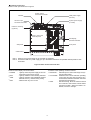
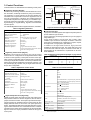
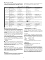
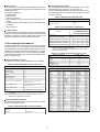
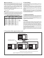
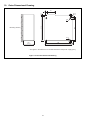
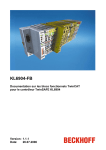
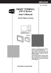
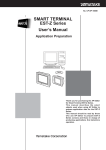
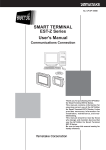
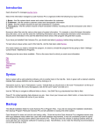
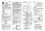
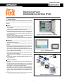
No.SS2-FLC100-0010P
Specification
Harmonas-FLeX
Distributed controller (FLC)
1. Introduction
The FLC is a compact controller designed with an eye towards
installation in a board. The FLC has the following functions and
features:
·
·
·
·
·
·
·
·
·
·
Control
The FLC has functions equivalent to those of a full-scale process controller.
It can be used for executing both PID control and sequence
control and it is provided with various functions.
Program creation and maintenance can be performed with
the integrated engineering environment RTC. Debugging can
be performed easily by conducting virtual simulation on a
personal computer.
Programs can be displayed with charts using the logic block
and function block for easy observation.
Created programs can be displayed in the form of drawings.
Figure 1. Example of Installation in a Board
Installation
Compact type controller that can be installed in a small-size
standard board (400 400).
Mountable on an existing self-standing board or wall-hang
board.
Built-in external wiring terminal board, cable connecting the
input/output card with the terminal board, power supply wiring for field device signal and short protection circuit.
As it can be connected directly with the field wiring, installation is completed by just installing FLC and connecting the
power supply with the field wiring.
368 input/output points at the maximum (approximately 256
points with a usual combination).
Various types can be combined in accordance with the application.
Environment-endurable design that allows operation in an encapsulated board.
Figure 2. EST555Z/EST240Z
Harmonas
PlantWalker-HV
System Compatibility
Redundant controlling Ethernet is equipped for standard specifications.
A programmable indicator [EST555Z] can be connected to
perform graphic monitoring and collecting and storing data.
This system can be used as a digital recorder.
Developable to a system such as the cooperative automation system Harmonas by connecting a controlling Ethernet
cable. The FLC can be introduced for each local board individually, making stepwise networking and systemization possible.
Harmonas-FLeX
Note: Refer to CP-SS-1800 for the specification sheet of the programmable indicator
“EST555Z,” and to CP-SS-1700 for that of the “EST240Z.”
Figure 3. ISystem Architecture
1
2. Functional Overview
··
··
·
The FLC consists of a main unit and three expansion units at
the maximum, and each unit has 6 I/O slots to mount I/O cards.
When using an expansion unit, mount an interface card for the
expansion unit to an I/O slot of the main unit, and mount similarly an interface card for interfacing with the main unit to each
expansion unit, and connect them with a dedicated cable. The
remaining I/O cards can be combined with the following cards
of the necessary number and mounted.
AI [4 - 20 mA/1 - 5 VDC] : 8 points/card
AO [4 - 20 mA] : 8 points/card
RTD : 8 points/card
DI : 16 points/card
DO [Semiconductor output] : 16 points/card
DO [Relay output] : 16 points/card
(In relay output, one card occupies two slots.)
Indicator I/F : 1 port/card (Mounted to the main unit.)
In addition, Ethernet is adopted for the control network and connection to other systems, and information systems such as the
cooperative automation system Harmonas can be made easily.
The control network is provided with a dual port for the standard specification.
··
Specifications
Table 1. Hardware Specifications
Item
CPU
Specifications
32 bits
Largest configuration when three expansion units are connected
- 23 I/O cards at the maximum (When the EST is connected, 22 cards at the maximum.)
- HLAI: 184 points (maximum), 8 points/card
- AO: 184 points (maximum), 8 points/card
- DI: 368 points (maximum), 16 points/card
- DO: 368 points (maximum), 16 points/card
Number of I/O points
- RTD AI for room temperature: 184 points (maximum), 8 points/card, fixed range of - 20 to 80
Note: The maximum number of points shown above is the restriction for the mounted slots when three expansion
base units are connected.
A certain restriction on the number of cards for practical use may be given from the control functional
performance point of view.
Configuration with only the main unit
- 6 I/O cards (5 cards if the EST is connected.)
Table 2. Specifications for Communication
Item
Host communication (Harmonas
system, etc.)
Communication between
controllers
I/O communication
Local indicator (EST)
communication
Specifications
Ethernet 10 Mbps, 400 PPS at the maximum (parameter/second: 400 PPS in total with communication between
controllers)
Available through Ethernet, 400 PPS at the maximum (parameter/second: 400 PPS in total with host communication)
Dedicated parallel bus
(An I/O slot of the main unit is occupied for the interface with the expansion units. No occupancy on the expansion
unit side.)
1:1 communication with the controller through RS232 or RS485
Models that can be connected are EST555Z and EST240Z.
(An I/O slot of the main unit is occupied for the interface.)
Table 3. Software Specifications
Item
Adjustment control point
Adjustment control algorithm
Control cycle
Sequence
Specifications
Adjustment control point: 32 points
Adjustment PV point: 32 points
19 types (48 formulas)
Select the basic cycle from 0.1, 0.2, 0.5 and 1 second (CL is fixed to 1 second.)
Partly, 0.1 second execution processing is possible (CL is also possible.)
128 (Maximum)
6080 MU: 18240 - 24480 statements
(The CL memory has no relation with other functions and can be used as a dedicated memory.)
64 points
1024 blocks at the maximum
25 algorithms
128 points at the maximum
2048 blocks at the maximum
SAMA function block
91 algorithms
(When monitoring from the DOSS/HSS is necessary, it is allocated to the numeric value variable or the flag
variable.)
256 points at the maximum
Digital composite
8192(Note 1) + (80 ( number of sequences used)
Numeric value variable
8192(Note 2) + (128 ( number of sequences used)
Flag variable
32 points
Timer variable
Note 1: 3,000 points are for use by the user, and the rest is reserved for the system.
Note 2: 3,000 points (including 512 for alarm) are for use by the user, and the rest is reserved for the system.
Logic
2
Installation environment conditions
Installation environment conditions for a single installation are
shown in the following table. For a single installation, provide
clearances of the specified dimensions around the main unit.
In addition to the following conditions, pay appropriate attention to the external magnetic field, electrostatic discharge, radio interference, etc.
Table 4. Installation Environment Conditions
Item
Ambient temperature
(Note 1)
Relative humidity
Range (
Standard operating
conditions
Normal operating
conditions
Marginal operating
conditions
Conditions for storage
and transportation
23 2
0 to 50
0 to 50
0 to 50
5
20
5 to 95
Note2
(0.020kg/kg')
0.35 mm or lower
(2 to 9 Hz)
1m/s2 mm or lower
(9 to 150 Hz)
20
5 to 95
(0.020kg/kg')
0.35 mm or lower
(2 to 9 Hz)
1m/s2 mm or lower
(9 to 150 Hz)
5 to 95
(0.020kg/kg')
1.5 mm or lower
(2 to 9 Hz)
5m/s2 mm or lower
(9 to 150 Hz)
)
Rate of change (
/h)
(% RH)
50 10
Amplitude
0
Acceleration
0
Vibration (Note 3)
Note 1: The atmosphere for use shall not include any corrosive gas. It is recommended to install in the control panel with a temperature of 45
Note 2: Maximum relative humidity (ratio of mass, kg/kg between wet air and dry air)
Note 3: Do not install in a place in which strong vibration is applied continuously.
or lower.
Input and output specifications
Table 5-1. Input and Output Specifications
Item
Analog input specifications
Number of points
Input power supply voltage and
consumption current
Input signal
Input range (FS)
Accuracy
Repeatability
Insulation
Input impedance
Transmitter power supply
Number of points
Input power supply voltage and
consumption current
Temperature input
(Room temperature, outside air Input signal
temperature, etc.)
Accuracy
Insulation
Allowable wiring resistance
Analog output
24 VDC ( 10%, 70 mA (When the transmitter* power supply is not used.)
1 to 5 VDC (0 to 100%)
0.726 to 5.276 VDC ( - 6.9 to 106.9%)
0.5% F.S. (factory-shipped adjustment, under the environment of 25
2
0.5% F.S.
Common insulation with the input power supply and system power supply
Differential input for use between channels (allowable operating voltage
1 MΩ or higher
18.6 to 26.4 VDC, 200 mA or more at the maximum
(8 points, prepared for each common card)
8 points
24 VDC
10%, 70 mA
PT 100 Ω, New JIS - 20 to 80 , fixed range
1% F.S. (under the environment of 25
2 )
Common insulation with the input power supply and system power supply
5 Ω or lower
4 to 20 mA (0 to 100%)
2.9 to 21.1 mA (- 6.9% to 106.9%)
0.5% F.S. (factory-shipped adjustment, under the environment of 25
Repeatability
Insulation
0.5% F.S.
Common insulation with the input power supply and system power supply
Maximum load resistance
Number of points
Input circuit
Common
Input power supply voltage and
consumption current
300 Ω
16 points/card
Photocoupler input (selectable for each source, or sink or card)
16 points common
Input impedance
Input filter time constant
Insulation
Input type
)
3 V)
Number of points
Output power supply voltage
and consumption current
Output range
Output scope
Accuracy
Input signal
Digital input
Specifications
8 points/card
8 points/card
24 VDC
10%, 140 mA (at 100% output on all points)
24 VDC
2
)
10%, 100 mA (When all points are ON.)
ON: 18 V or higher (2.4 mA or higher)
OFF: 6 V or lower (0.8 mA or lower)
6.8 kΩ
10 ms
Insulated from the system power supply and not insulated from input power supply
Status-type, or latch-type (push button) input or counter-type
Specifiable for each point (depending on the software)
Latch type DI input detection
width
100 ms or more
Integratable pulse width
100 ms or more (200 ms or higher at ON/OFF)
*Remarks: The transmitter power supply is not insulated from the input power supply.
When the transmitter power supply is used, the input side becomes common and differential input cannot be performed.
When connecting a two-wire transmitter or 4 to 20 mA input, install a 250 ( resistor to the external terminal.
3
Table 5-2. Input and Output Specifications (Continued)
Item
Digital output
Specifications
Number of points
16 points/card
Output circuit
Open collector
Common
Output power supply voltage
and consumption current
16 points common
Maximum key current (load
current)
Maximum 0.5 A (for one point)
Output transistor ON voltage
Insulation
10%, 10 mA (When all points are OFF.)
Maximum 2 A (for one card)
1.5 V or lower (When the load current is 0.5 A.)
Pulse-type DO pulse width
Number of points
Insulated from the system power supply and not insulated from the output power supply
Latch-type (status) output or pulse-type output, specifiable for output of each point
(Depending on the software)
100 ms to 120 s, 100 ms resolution
16 points/card
Output circuit
Make (A contact)
Output power supply voltage
and consumption current
24 VDC
Contact rating
250 VAC 2A (resistance load)
30 VDC 2A (resistance load)
Operating time
10 ms or less
Reset time
Output transistor leak current
Insulation
5 ms or less
1.5 V or lower (with 24 VDC)
Insulated from system power supply and output power supply
Output type, pulse width
Same as open collector output
Output type
Digital output
(When a relay terminal panel
is used.)
24 VDC
16 points
10 %, approximately 150 mA (When relay 16 points excited)
Model
Table 6. List of Models
varnish
finished
HD-FXFLC00P
*
*
*
*
*
Model
*
*
*
*
Name
Remarks
Main unit: With field power supply
HD-FXFLC00PE
Main unit: With field power supply + With expansion unit I/F board
HD-FXFLC00N
Main unit: Without field power supply
Controller/main unit
(Either one shall be selected.)
HD-FXFLC00NE
HD-FXSWFLC20
Main unit: Without field power supply + With expansion unit I/F board
FLC license
Necessary for each main unit
HD-FXFLE00P
Expansion unit: With field power supply
HD-FXFLE00N
Expansion unit: Without field power supply
HD-FXDCBX00
HD-FXEXPNL
HD-FXCBL01
HD-FXCBL02
HD-FXCBL03
Expansion unit I/F board (3 ports on the main unit side)
Front panel for connecting the expansion unit (A part on the main unit side)
Expansion unit connection cable: 1 m
Expansion unit connection cable: 2 m
Expansion unit connection cable: 3 m
HD-FXAIPS00
Controller/expansion unit
(Either one shall be selected.)
Necessary when connecting an expansion
unit to the main unit without an expansion
unit I/F
Necessary when expanding the
input/output
Analog input card (with terminals)
*
HD-FXRTDPS0
*
*
*
*
*
HD-FXAOPS00
Temperature measuring resistor card (Air conditioning specifications: - 20
to 80 , with terminals)
Analog output card (with terminals)
HD-FXDIPS00
HD-FXDOPS00
Digital input card (with terminals)
Digital output card (SS output, with terminals)
HD-FXDYPS00
Digital output card (with relay terminals)
HD-FXESTS00
HD-FXWMCAB0S
EST smart terminal I/F card
Standard board (S size): Wall-hang board type: for installing EST240Z
HD-FXWMCAB0M
HD-FXWMCAB0L
Standard board (M size): Wall-hang board type: for installing EST555Z
Standard board (L size): Freestanding board type: for installing EST555Z
HD-FXSWRTCF
RTC_FLEX (software)
: For varnish finished products, a "C" is affixed to the end of the model number.
4
Input/output card
Necessary when connecting the EST
Functions of each part
Names of each part are shown in Figure 4.
Breaker
24 VDC output
connection terminals
Field power supply
(24 VDC)
100 VAC input
connection terminals
System power supply
(3.3 VDC)
Holes for mounting
(4 places)
Area to mount the
terminal panel
LED display,
operation switches
Side panel
Front panel
Cable shield
Note 1: Wiring for 3.3V power supply for the controller is completed.
Note 2: Connect the field 24 V power supply (2.2 A) to the feeder terminal on the specified terminal panel for each
I/O module.
Figure 4. Name of each Part of the FLC
Functions of the display unit are as follows:
POWER
: Lights up when the power supply of the communication control unit is normal.
RUN
: Lights up while the control is being executed.
SAVE
: Lights up when the control database exists in
the flash memory. Flashes during saving.
ERR.
: Flashes when any error occurs.
Functions of the operating unit are as follows:
RUN/STOP : Starts/stops the control and brings the system into idling status.
LOCAL/RMT.: Switches to the LOCAL side when operating
control start and stop with the above-mentioned switch; switches to the RMT. side when
operating through the RTC.
SAVE
: Executes saving. Move the switch to the left
and continue to hold it there until the SAVE
LED starts to flash. When the switch is released, it returns to the right.
·
··
·
·
·
·
5
3. Control Functions
Commanded state (OP)
(from operator or user program)
Control functions are classified into the following control points:
Regulatory PV Point (RegPV)
Standard I/O processing functions, like industrial unit conversion and alarm, are directly carried out by using I/O monitoring.
The regulatory PV point achieves the process variable (PV)
calculation and compensation functions. Algorithms such as
flow rate compensation, integration and variable dead time
compensation implement PV processing. It is available to provide more enhanced configuration such as alarm suppression,
signal filtering, etc. Signal filtering, algorithm and calculation
formula options.
For available algorithm and other supported functions, see Table 7.
Input
(up to 2 inputs)
Data acquisition
Flow rate compensation
Middle of three
High/low/average selector
Summer
Integration (totalizer)
Variable dead time
Lead/lag compensation
General linearization
Calculator algorithm
Support function
Output
(up to 3 outputs)
10 11 12
Override "Forced"
Logic Point (Logic)
Logic points are used together with digital composite points to
provide interlock logic functions.
A logic point has a processing equivalent of up to two pages of
relay ladder logic.
A logic point consists of a logic block, flag, numeric value
variable, input connection and output connection. Three are
three types of combinations in configuration of inputs, outputs,
and logic block of a logic points. (See Table 9)
In addition to the logic block functions, logic points are
available as data transfer points. This reads data from input
connections and makes an output connection of this data, so
that the data can be transferred to a parameter of other defined databases.
PV source(Automation, manual,
substitution)
PV clamp
Engineering unit conversion and
extended PV range check
PV status
PV filtering
PV alarm
- Bad PV
- Upper and lower limits of PV
- Upper-upper/Lower-lower limits of PV
- PV rate of change alarm
Table 9. Maximum Configuration Example of Logic Points
Configuration
Type
Input
Output
Logic block
12
12
12
4
8
12
16
8
0
Option 1
Option 2
Option 3
Note: Each logic point provides six status flags, six user flags and four numeric value variables.
Table 10. Logic Block Algorithm
Table 8. Adjustment Control Points
PID
With PID field forward
With PID external feedback
Position proportion on/off
control
Ratio control
Lamp/soak
Automatic/manual station
Speed type addition
Switch
Override selector
Forced output
Interlock
Figure 5. Structure of Digital Composite Points
Regulatory Control Point (Reg Ctl)
Regulatory control points are used to carry out the control
functions of FLC. Configuration of the algorithms listed in Table
8 carries out the regulatory control point functions. Each algorithm contains configurable options and achieves complicated
control by a simple menu selection. Functions provided as standard functions include initialization and windup protection. The
set point lamping (by operator entry of target values and lamp
time) is also configurable.
Available algorithm
Operation permission
Interlock
P0 P1 P2
Permissive "Permission"
Table 7. Regulatory PV Points
Available algorithm
Off nomal
Command disagree
Un-commanded
change alarm
Current status
(PV)
Support function
Mode/mode attribute
Red tag
Initialization
Windup protection
Logic
AND
OR
NOT
NAND
NOR
XOR
QUALIFIED-OR 2 (2-input majority decision)
External mode switchover
Safety cutoff
Limit (output)
PV source
PV alarm
- Bad PV
- Upper and lower limits of PV
- Upper-upper/Lower-lower limits of PV
- PV rate of change alarm
QUALIFIED-OR3 (3-input majority decision)
Comparison
EQ (= with dead band)
NE ( with dead band)
GT (> with dead band)
LT (< with dead band)
LE ( dead hand)
DELAY
Digital Composite Point (Dig Comp)
Digital composite points are multi input and multi output points
that provides interface to discrete equipment, like the motors,
pumps and solenoid valves. These points provide interlock processing functions as standard functions. These points can also
display interlock states on the screen of an open supervisory
station. The displayed states have information effective for tracking the cause of interlock. The “ / local / hand / off / auto / ” switches
generally used for motor driving equipment can also be handled.
Figure 5 shows the major parameters related to this type of
control point.
Delay
ON DELAY
OFF DELAY
FIXPLS (fixed length pulse)
Pulse
Watch dog timer
MAXPLS (maximum time limit pulse)
MINPLS (minimum time limit pulse)
WATCHIDOG
Flip flop
Input error check
Switch
FLIPFLOP
CHECKBAD
SWITCH
Change detection
CHDETECT
Note: AND, OR, NAND and NOR gates accept three inputs per block. Options are available to inverse inputs.
6
Function Block Point (FB)
Function block point consists of 91 types of function blocks (see
Table 11). Up to 2048 function blocks are available per point.
Conforming to a block notation system called SAMA (Scientific
Apparatus Makers Association), these function blocks can construct control functions by a logic diagram system.
Table 11. Function Block Algorithm
Arithmetic operation
(8 types)
Single number value
variable (13 types)
ADD (addition)
SUB (subtraction)
MUL (multiplication)
DIV (division)
MOD (modulo)
EXPT (exponent xy)
SUM (4-point addition)
DADD (digital addition)
ABS (absolute value)
SQR (square)
SQRT (square root)
LN (logarithm natural)
LOG (customary logarithm)
EXP (exponent ex)
SIN (sine)
COS (cosine)
TAN (tangent)
ATAN (arctangent)
TRUNC (truncation)
ROUND (rounding)
PSQRT (percent square root)
Selection (9 types)
Detection (12 types)
MAX (maximum value)
MIN (minimum value)
AVG (average value)
HSE (high selector)
LSE (low selector)
MID3 (middle of three)
SW (switch)
SFT (softening switch)
ALSW (alternate switch)
HLM (high limiter)
LLM (low limiter)
DRL (rate-of-change limiter)
HMS (high monitor)
LMS (low monitor)
DRM (rate-of-change monitor)
DMS (deviation monitor)
NUMCHK (normality check)
BADCHK (badness check)
INFCHK (infinity check)
QLTCHK (change check 1)
CHGCHK (change check 2)
ETP (% conversion)
FUNC (function conversion)
CONV (data type conversion)
Conversion (4 types) PTE (EU value conversion)
Logical operation
(11 types)
Comparison (6 types)
Pulse (3 types)
Timer (5 types)
AND (logical product)
OR (logical sum)
NOT (inversion)
NAND (inverted logical product)
NOR (inverted logical sum)
XOR (exclusive logical sum)
QOR2 (2-input majority decision)
SR (set)
RS (reset)
ORIN4 (4-input logical sum)
ANDIN4 (4-input logical product)
EQ (= with dead band)
NE ( with dead band)
GT (> with dead band)
LE ( dead band)
GE ( with dead band)
LT ( < with dead band)
FIXPLS (fixed length pulse)
MAXPLS (maximum time limit pulse) MINPLS (minimum time limit pulse)
CYCPLS (timer)
WDT (watch dog timer)
DELAY (delay)
ONDLY (on delay)
OFFDLY (off delay)
Counter (4 types)
UCNT (up counter)
DCNT (down counter)
AAV (analog integration)
PAV (pulse integration)
Control operation
(8 types)
PID (PID operation)
PRO (proportion)
INT (integration)
DIF (differentiation)
DLTPV (speed type PV)
Others (7 types)
LDLG (leading/delay)
DED (waste time)
TF (filtering time)
RMP (lamp)
MAV (movement average)
ANMA (analog memory)
GW (gate way)
SG (single)
FL (flag)
TIMFL (one shot FL)
REDTAG
Process Module Data Point (Proc Mod)
Process control often requires flexible control programs that are
also available for continuous process, batch or hybrid applications. Process module data point is a user created program (CL
program) written in special-purpose control language. This
language provides powerful sequence control and calculation
functions.
CL programs can access analog input and output, digital input
and output, logic block status, alarm status, failure status,
numeric value variables, and flags.
Process module data points provide phase, step and statement
structures suitable for implementing batch process control functions. They can also activate a sequence for hold, shutdown, or
emergency shutdown by means of the powerful function of the
multilevel error processing.
4. Alarm System Functions
FLC supports alarm functions. If alarms occur, these alarms
are notified onto an open supervisory station via various types
of screens. Alarms are generally classified into PV alarms and
digital alarms.
PV Alarm
For access variables, configurable PV alarms are as follows.
Methods are available for setting alarms in I/O points or in control points. In general, if a control point uses an I/O point, an
alarm is set in a control point. Otherwise, it is set in an I/O point.
High
Change rate high
High high
Change rate low
Low
Significant change
Low low
A dead band can be set in all PV alarms mentioned above.
··
··
Flag Point
Flag points indicate two states, such as on and off, and accepts
entries of Boolean algebra values. Flag points can be changed
by operators and user programs. Per FLC, 8192 flags are prepared. Of these flags, the first 512 flags support off-normal
alarms (generates alarm at status on).
··
·
Digital Alarm
Digital alarms are divided into the following three types:
Off normal alarm
Uncommanded change alarm
Command disagree alarm
Off normal alarms are simply generated when the status is on.
Both uncommanded change alarms and command disagree
alarms are set within digital composite points and detect a disagreement between input and output. A command disagree
alarm detects a disagreement between input and output just
after an output change, while an uncommanded change alarm
detects a disagreement between input and output when no output change is made. Both alarms can set dead band time.
··
·
Numeric Value Variable Point
Numeric value variable points are numeric value variables that
literally save real values and are effective for batch (recipe) operations. Per FLC, 8192 numeric value variable points are prepared. Like flag points, numeric value variable points are not
included in the point processing schedule.
Timer Point
Timer points are effective for operators and user programs to
supervise process events. Timer points are processed once
every second. Per FLC, 32 timer points are prepared.
7
Alarm Priority
Alarm priority can be configured for individual alarm types for
each point. Selectable alarm priorities can be divided into the
following five types:
Emergent (emergency)
Important (high)
Ordinary (low)
Record only (journal)
Only journal printer output (not used when the EST is connected)
Journal recording + printer output (not used when the EST is
connected)
None (no action)
Processing Unit (PU Value)
This unit represents the processing capability of FLC, determined based on the point types, control cycles, etc.
PU values differ depending on point types and control cycles.
The following table lists the maximum PU values per FLC and
PU values at points.
··
··
·
·
·
Table 14. Maximum PU Value (Per FLC)
Point Type
Total of control points and function blocks
and of I/O points
700
Table 15. List of PU Values of I/O Points
PU Value
Contact Cutout
The contact cutout function allows a program to temporarily stop
an alarm for each point having alarm functions. The “CONTCUT”
parameter, prepared for the points having alarm functions, can
be set to on to put the points in the alarm stop status.
Device
5. Processing Performances
Combining adjustment control loops, logic functions, sequence
and I/O processes, FLC can configure control functions according to applications. The configuration needs to take into account
restrictions on the maximum number of points per FLC, the processing unit (PU value), which is a unit of processing capability,
and the memory unit (MU value), which is a permitted memory
unit of CL program size.
I/O Monitoring Cycle
1sec 0.5sec 0.2sec 0.1sec
Main unit
2.0
Expansion unit (for each unit)
4.0
-
Digital input (DI) (for each card)
-
0.7
1.1
2.3
Digital output (DO) (for each card)
-
0.2
0.4
1.0
4.3
2.0
Analog input (AI) (for each card)
-
1.5
2.2
4.3
7.8
Analog output (AO) (for each card)
-
0.3
0.6
1.5
3.0
Note: In AI, it is assumed that two alarms (occurrence or restoration) at a
time occur every second in the 4 slots.
In DI, it is assumed that one off-normal alarm at a time occurs
every second in the 8 slots.
Table 16. List of PU Values (Control Cycle = 1 sec)
Control Point Name
1sec PU Value
RegPV
RegCtl
Logic
DigComp
ProcMod(short)
ProcMod(long)
Maximum Number of Points
The maximum number of points settable per FLC is as follows.
Table 12. Maximum Number of Points (per FLC)
Point type
PU value
0.8
1.1
0.7
0.1
1.0
2.0
Maximum number of points
Regulatory control
Regulatory PV
Process module
Logic
Digital composite
Function block
32
32
128
64
256
128
Numeric value variable (NN)
8,192(Note 1) + (80 ( number of
sequences used)
Flag variable (FL)
8,192(Note 2) + (128 ( number of
sequences used)
Timer variable (TM)
I/O point
32
(Number of points per module 24)
Function Block
ADD
SUB
MUL
DIV
MOD
EXPT
SUM
DADD
ABS
SQR
SQRT
LN
LOG
EXP
SIN
COS
TAN
ATAN
TRUNC
ROUND
PSQRT
MAX
MIN
AVG
HSE
LSE
MID3
SW
SFT
ALSW
HLM
Note 1: 2,047 points are for use by the user, and the rest is reserved for
the system.
Note 2: 2,047 points (including 512 for alarm) are for use by the user,
and the rest is reserved for the system.
Maximum Number of Blocks
The following restrictions apply to the function blocks, components of function block points.
Table 13. Maximum Number of Function Blocks
Function block point
Per point
2048 blocks
Per FLC
2048 blocks
8
1sec,
PU Value
0.027
0.027
0.027
0.027
0.022
0.027
0.031
0.031
0.018
0.018
0.018
0.027
0.027
0.027
0.027
0.027
0.027
0.027
0.027
0.027
0.018
0.031
0.031
0.031
0.027
0.027
0.031
0.027
0.044
0.022
0.018
Function Block
LLM
DRL
HMS
LMS
DRM
DMS
NUMCHK
BADCHK
INFCHK
QLTCHK
CHGCHK
PTE
ETP
FUNC
CONV
AND
OR
NOT
NAND
NOR
XOR
QOR2
SR
RS
ORIN4
ADDIN4
EQ
NE
GT
GE
LT
1sec,
PU Value
0.018
0.044
0.018
0.018
0.044
0.027
0.018
0.018
0.018
0.018
0.027
0.022
0.022
0.031
0.035
0.022
0.022
0.022
0.022
0.022
0.022
0.027
0.022
0.022
0.031
0.031
0.027
0.027
0.027
0.027
0.027
Function Block
LE
FIXPLS
MAXPLS
MINPLS
CYCPLS
WDT
DELAY
ONDLY
OFFDLY
UCNT
DCNT
AAV
PAV
PID
PRO
INT
DIF
LDLG
DED
TF
DLTPV
RMP
MAV
ANMA
GW
SG
FL
TIMFL
REDTAG
1sec,
PU Value
0.027
0.027
0.027
0.027
0.031
0.027
0.018
0.031
0.031
0.022
0.022
0.031
0.031
0.083
0.027
0.053
0.070
0.044
0.040
0.053
0.027
0.035
0.048
0.031
0.022
0.018
0.018
0.031
0.018
Memory Unit (MU Value)
Memory unit value is a unit value indication that helps user in using
memory of FLC, this determines the total size of CL programs.
Memory unit values are used to store CL programs themselves.
For MU value calculation, a CL program is divided into three
statements. An MU value is then found by the quantity of statements. Each division is called a CL block, with 1CL block = 1 MU.
The maximum MU value per FLC is 6080.
Different from PU values, MU values are not affected by control
cycles or the number of I/O points.
6. Smart Debug
The smart debug function can check operations of various control functions and I/O processing functions provided by FLC without using I/O modules.
This function can be carried out per FLC. After the transition to
the debug mode, the function neither receives inputs from I/O
modules nor transmits outputs to I/O modules, except for performing controlling operations within FLC and I/O processing
operation.
Engineers can set any values on FLC as virtual process data,
making the debugging of CL programs, etc., easy. Engineers
can operate and supervise the status of the debug mode on the
Harmonized supervisory station.
Control Cycle
Control cycles are selectable per FLC from among 1 sec, 500
msec, 200 msec and 100 msec (for combinations, see Table 17).
In addition to the control cycles, some of the data points can be
processed at high speed (100 ms) by means of fast scan function.
7. Software Simulation
Table 17. Combination of Control Cycles
SCANRATE
Parameter
Reg1 Log1
Reg1 Log2
Reg1 Log5
Reg1 Log10
Reg2 Log2
Reg2 Log5
Reg2 Log10
Reg5 Log5
Reg5 Log10
Reg10 Log10
Fast scan
The software simulation function (option) allows standalone PCs
to virtually carry out functions of FLC. Using this function enables creating and verifying (debugging) applications in an environment without actual machines. One PC can perform those
operations for more than one FLC.
Point Type
、
RegcTl、
RegPV
1sec
1sec
1sec
1sec
500msec
500msec
500msec
200msec
200msec
100msec
100msec
、
Logic、
DigComp
1sec
500msec
200msec
100msec
500msec
200msec
100msec
200msec
100msec
100msec
100msec
PromMod
1sec
1sec
1sec
1sec
1sec
1sec
1sec
1sec
1sec
1sec
100msec
FB
Selection of the
following control
cycles per point
・1sec
・500msec
・200msec
・100msec
8. Restart
The FLC restarts operation based on data from the flash memory
on the CPU card (CTC) at a time of normal restart. It is designed so that, at restart, the necessary startup operations become minimal, while the status of the process is maintained.
The control loop performing output to the field is switched into
the manual mode, and the sequence can be selected from
among automatic start from the beginning, stop at the first step,
or stop at the last execution position.
Data save to the flash memory can be manually performed with
switches on the front panel of the controller or on the local indicator.
9. Connection of the expansion base units
Main unit (master side)
The expansion unit I/F board is
mounted to the bottom I/O slot.
The length of the cable
must not exceed 3 m.
Expansion unit -1 (Slave side)
Expansion unit -2 (Slave side)
Expansion unit -3 (Slave side)
Install the main unit and the expansion units in the same board.
Figure 6. Diagram for Connection of the Expansion Base Unit
9
10. Outer Dimensional Drawing
23
98
R4.5
13
13.5
9
18
280
310
Mounting surface
280
136
(127)
9
25
8
R4.5
325
*: The figure in the brackets is for models without the field power supply (24 V)
Figure 7. FLC Outer Dimensional Drawing
10
(This page intentionally left brank.)
11
• Windows 2000, Windows, MS are trademarks of Microsoft Corporation of USA and other countries.
• Ethernet is a trademark of the XEROX Corporation of USA.
• Pentlium is a trademark of Intel Corporation of USA.
• Other product names, model nos., company names are trademarks of each company.
Specifications are subject to change without notice.
Savemation
Saving through Automation
New Stage Yokohama Building 1-1-32, Shin-urashima-cho, Kanagawa-ku,
Yokohama 221-0031, JAPAN
Tel : 81-45-461-8823
http://jp.yamatake.co/
0310-Y/Y
This has been printed on recycled paper.
12