1
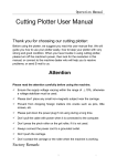
PF2100 Modbus Card Instruction Manual v1.1 Jan 5, 2012 by Ryan Northcott Table of Contents Description ............................................................................................................................................................................................................................................... 1 Quick Start Checklist ................................................................................................................................................................................................................................ 2 Specifications and System Requirements ................................................................................................................................................................................................ 3 PF2100 System Requirements ............................................................................................................................................................................................................. 3 Modbus Master Device Requirements ................................................................................................................................................................................................ 3 Modbus Card Specifications................................................................................................................................................................................................................. 4 Included Components .............................................................................................................................................................................................................................. 5 DIP Switch Settings................................................................................................................................................................................................................................... 6 Installing the Card .................................................................................................................................................................................................................................... 7 Procedure When Another Expansion Card is Preinstalled ................................................................................................................................................................... 7 Procedure When No Expansion Card is Preinstalled ........................................................................................................................................................................... 8 System Considerations ............................................................................................................................................................................................................................. 9 Cable Type ............................................................................................................................................................................................................................................ 9 Duplex .................................................................................................................................................................................................................................................. 9 Wiring Topology ................................................................................................................................................................................................................................... 9 Termination........................................................................................................................................................................................................................................ 10 Baud Rate ........................................................................................................................................................................................................................................... 10 Number of Devices............................................................................................................................................................................................................................. 10 Turn-Around Delay ............................................................................................................................................................................................................................. 11 Signal Naming Conventions ............................................................................................................................................................................................................... 11 Common Ground ............................................................................................................................................................................................................................... 11 Electrical Wiring ..................................................................................................................................................................................................................................... 12 PF2100 Modbus Card Instruction Manual v1.1 Jan 5, 2012 ©2011 Profire Energy Inc Page i The Pluggable Header ........................................................................................................................................................................................................................ 12 Connecting the Communication Wires .............................................................................................................................................................................................. 12 Connecting the “GND” Pin ................................................................................................................................................................................................................. 13 Configuring the Menu Settings .............................................................................................................................................................................................................. 14 Testing the Modbus Card ....................................................................................................................................................................................................................... 15 Using a Modbus Master ..................................................................................................................................................................................................................... 15 Using the LEDs.................................................................................................................................................................................................................................... 15 Using a PC Software Based Modbus Test Program ............................................................................................................................................................................ 15 Using a Network Analyzer, Logic Analyzer, or Oscilloscope .............................................................................................................................................................. 15 Appendix A – Modbus Background Info ................................................................................................................................................................................................ 16 Appendix B – Using the PF2100 Menu System ...................................................................................................................................................................................... 17 Menu Structure .................................................................................................................................................................................................................................. 17 Navigating Menus .............................................................................................................................................................................................................................. 17 Viewing Menu Items .......................................................................................................................................................................................................................... 17 System Password ............................................................................................................................................................................................................................... 17 Editing a Menu Item Setting .............................................................................................................................................................................................................. 17 Saving an Edited Menu Item Setting .................................................................................................................................................................................................. 17 Reverting an Edited Menu Item Setting............................................................................................................................................................................................. 18 Menu Item Setting Storage ................................................................................................................................................................................................................ 18 Setting the System Voltage ................................................................................................................................................................................................................ 18 Resetting the System to Factory Defaults.......................................................................................................................................................................................... 18 Appendix C – Modbus Register Numbers .............................................................................................................................................................................................. 19 Discrete Table .................................................................................................................................................................................................................................... 19 PF2100 Modbus Card Instruction Manual v1.1 ©2011 Profire Energy Inc Jan 5, 2012 Page ii Analog Tables ..................................................................................................................................................................................................................................... 19 Command Register ............................................................................................................................................................................................................................. 20 Appendix D – Troubleshooting .............................................................................................................................................................................................................. 21 Menu 6 Does Not Exist on my PF2100 ............................................................................................................................................................................................... 21 The “Run” LED is Not Blinking ............................................................................................................................................................................................................ 21 The “RX” LED Does Not Light When the Master Sends a Command ................................................................................................................................................. 21 The “TX” LED Does Not Light When the Master Sends a Command ................................................................................................................................................. 22 The “TX” LED Blinks but the Master Receives Garbage Data............................................................................................................................................................. 22 PF2100 Modbus Card Instruction Manual v1.1 ©2011 Profire Energy Inc Jan 5, 2012 Page iii Description The Modbus Card is an Expansion Card designed for use with PF2100 Burner Management Systems. It implements a Modbus Slave Device which allows settings and measurements in the PF2100 to be read remotely by a PLC or other remote Master Device. A future firmware update will enable Master Devices to remotely change settings in the PF2100. The protocol used is Modbus RTU and the physical implementation is half-duplex RS-485. The baud rate is user selectable between 9600 and 19200 bps. Note that there are two different versions of the card: Figure 1 PF2100 Modbus Card Instruction Manual v1.1 ©2011 Profire Energy Inc Jan 5, 2012 Page 1 Quick Start Checklist Follow these steps in order to install and setup the Modbus Card properly. Check off each step after it is completed to ensure that you don’t miss a step. More detailed information on how to complete each step is located in later sections of this document. Preparation: □ 1. Verify System Requirements. See instructions on page 3. □ 2. Verify Included Hardware. See instructions on page 5. □ 3. Verify DIP Switch Settings. See instructions on page 6. □ 4. Disconnect Power to Your PF2100 System. Install and Wiring: □ 5. Install the Modbus Card in Your PF2100 System. See instructions on page 7. □ 6. Review the Entire Modbus System Setup to Identify any Necessary Changes. See instructions on page 9. □ 7. Wire up the RS-485 Interface. See instructions on page 12. Menu Settings: □ 8. Enable the Modbus Card and Select an Address. See instructions on page 14. Testing: □ 9. Verify that the Modbus Card is Working Correctly. See instructions on page 15. PF2100 Modbus Card Instruction Manual v1.1 ©2011 Profire Energy Inc Jan 5, 2012 Page 2 Specifications and System Requirements This manual was written for use with Modbus Cards that have the following model and version: Model Number Hardware Version Firmware Version 1PS167 v1.0 / v2.0 v1.1 / v2.0 PF2100 System Requirements This input card is designed to be used only with PF2100 systems that meet the following requirements: Door Card Terminal Card Hardware Version Firmware Version Hardware Version Firmware Version v1.6 or higher v1.6.3CE or higher v1.61 or higher v1.6.3B or higher To check your firmware version, do the following with the PF2100 powered on. Simultaneously hold both the Up and Down buttons on the keypad. The Door Card firmware version (“DC”) must be v1.6.3CE or higher. If it is not, contact Profire to arrange for a firmware upgrade. If your system uses a higher revision of firmware than those listed in the table above, the menu descriptions listed in this document may not be completely accurate. In this case, please consult our website for a newer version of this manual. Modbus Master Device Requirements Modbus Master Devices (such as PLCs or computers) must be compatible with the Modbus Card specifications listed below. If the Master Device is not compatible with one or more of these specs, it may still be possible to make the system work using a repeater or other converter device. For example, if the Master Device only supports Modbus TCP, then a Modbus-TCP-to-Modbus-RTU Converter will allow the system to work as long as the Modbus RTU interface on the converter is compatible with the specifications below. PF2100 Modbus Card Instruction Manual v1.1 ©2011 Profire Energy Inc Jan 5, 2012 Page 3 Modbus Card Specifications The Modbus Card has the following specifications: Spec Operating Temperature: Value -40 C to +60 C RS-485 Signaling: Min Differential Receiver Voltage Absolute Max Receiver Voltage Typical Differential Driver Voltage Maximum Driver Short Circuit Current Termination Receiver Input Impedance 400 mV (A to B) 15 V (A to GND, B to GND) 5 V (Y to Z) +/- 250 mA None or 120 Ohms (user selectable) 96 kOhms Modbus Protocol: Protocol Baud Rate Parity Tx-to-Rx Delay Modbus RTU 9600 or 19200 bps (user selectable) None 2 or 25 ms (user selectable) Terminal Block: Maximum Wire Gauge 16 AWG Physical Dimensions (including components): Width Width (including pluggable header) Length Height Height (including standoff threads) 59.1 mm 68.1 mm 85.7 mm 25.5 mm 30.0 mm PF2100 Modbus Card Instruction Manual v1.1 ©2011 Profire Energy Inc Jan 5, 2012 Page 4 Included Components Your Modbus Card should have come with the following components. If any components are missing, please contact Profire immediately. A picture of these components is included in Figure 2. Item Modbus Card v1.0 / v2.0 Pluggable Header Aluminum Standoffs Phillips Machine Screws Hex Nuts Instruction Manual Quantity 1 1 4 4 4 1 Notes Pre-installed on the card Pre-installed on the card Pre-installed on the card This document Figure 2 PF2100 Modbus Card Instruction Manual v1.1 ©2011 Profire Energy Inc Jan 5, 2012 Page 5 DIP Switch Settings There are 4 DIP switches included on the Modbus Card v1.0 and 8 DIP switches on the Modbus Card v2.0. The default settings for these DIP Switches are shown in Figure 3 and Figure 5 respectively. You should ensure that the DIP switches are set according to your needs. The following tables describe the DIP switch functions: Modbus Card v1.0 # Function 1 Baud Rate 2 3 4 Rx to Tx Delay Unused Termination Modbus Card v2.0 # Function S1-1 Baud Rate 1 S1-2 S1-3 S1-4 S2-1 S2-2 S2-3 S2-4 Baud Rate 2 Protocol Termination Rx to Tx Delay 1 Rx to Tx Delay 2 Parity Enable Parity Odd/Even Description OFF = 9600 bps, ON = 19200 bps NOTE: Press the reset button on the card after changing the baud rate setting while the system is running OFF = 2ms, ON = 25ms OFF = 120 Ohm Termination, ON = No Termination NOTE: External termination with a different resistor value may be required for best performance if cable other than Cat-5e is used. Description OFF = 9600 bps, ON = 19200 bps NOTE: Press the reset button on the card after changing the baud rate setting while the system is running Ignored in the current firmware revision Ignored in the current firmware revision OFF = 120 Ohm Termination, ON = No Termination NOTE: External termination with a different resistor value may be required for best performance if cable other than Cat-5e is used. OFF = 2ms, ON = 25ms OFF = 2ms, ON = 25ms Ignored in the current firmware revision Ignored in the current firmware revision PF2100 Modbus Card Instruction Manual v1.1 ©2011 Profire Energy Inc Figure 3 S1 S2 Figure 4 Jan 5, 2012 Page 6 Installing the Card If your system did not have a Modbus Card preinstalled at the factory, follow these steps to install it. Otherwise, skip to the next section of this document. Figure 5 Before you begin, first inspect your terminal card to determine if there is another expansion card (such as a 4-20mA Input Card) already installed in your PF2100 system. There are separate procedures later in this section for the case where there is another card preinstalled and the case where there is not. Figure 6 Procedure When Another Expansion Card is Preinstalled 1. Shut off the power to the PF2100 system. 2. Remove the 4 machine screws from the expansion card that is already installed in your PF2100 system. See Figure 5. 3. Remove the 4 machine screws and 4 standoffs from the new Modbus Card that you are about to install. See Figure 6. 4. Attach the 4 standoffs to the expansion card that is Figure 7 already installed in your PF2100 system. Tighten to 4 in*lbs. Do not over tighten or the standoffs may break. See Figure 7. 5. Carefully install the new Modbus Card on top of the existing expansion card such that the long pinned Figure 8 header on the Modbus Card mates with the socket on the old expansion card. Be careful not to bend any pins while doing this. Continue to apply pressure to the Modbus Card until the header is fully inserted. See Figure 8. 6. Finish attaching the new Modbus Card to the old expansion card using the 4 machine screws that were previously removed. Tighten to 4 in*lbs. See Figure 8. 7. You are done installing the card! You should have the following extra parts left over which you can either discard or keep for future use: 4 machine screws and 4 hex nuts. PF2100 Modbus Card Instruction Manual v1.1 ©2011 Profire Energy Inc Jan 5, 2012 Page 7 Procedure When No Expansion Card is Preinstalled 1. Shut off the power to the PF2100 system. 2. Remove the 4 screws that hold the terminal card in place in the product enclosure. Do not lose these screws as you will need them later. See Figure 9. 3. Carefully install the Modbus Card onto the Terminal Card such that the long pinned header on the Modbus Card mates with the socket P1 on the Terminal Card. Be careful not to bend any pins while doing this. Continue to apply pressure to the Modbus Card until the 4 standoffs fit into the holes in the PCBA. See Figure 10. 4. On the back side of the Terminal Card, install 4 hex nuts onto the standoffs to hold the Modbus Card in place. Tighten to 4 in*lbs. Do not over tighten or the standoffs may break. See Figure 10. 5. Place the terminal card back into the product enclosure and fasten it using the 4 screws removed previously. Tighten to between 12 and 26 in*lbs taking care to not leave any screws loose enough that the terminal card rattles around and not too tight that the enclosure holes begin to strip out. See Figure 9. 6. You are done installing the card! There should not be any extra parts left over. If there are, double check if you have missed a step. Figure 9 Figure 10 PF2100 Modbus Card Instruction Manual v1.1 ©2011 Profire Energy Inc Jan 5, 2012 Page 8 System Considerations When installing the Modbus Card, it is important to consider the entire system in order to ensure proper operation of all devices. The system consists of all components that are on the same bus including the Master device, all Slave devices, the wiring, repeaters, and bus terminators. The following things should be considered before designing a new RS-485 bus or when adding devices to an existing bus: 1. Cable Type 2. Duplex 3. Wiring Topology 4. Termination 5. Baud Rate 6. Number of Devices 7. Turn-Around Delay 8. Signal Naming Conventions 9. Ground Cable Type The RS-485 signaling standard is intended to be used with twisted pair cable (such as Cat-5e) for best performance in noisy environments or in installations with long cable runs. Non-twisted pair cable may be acceptable for shorter cable runs but is generally not recommended. Ensure that you use 2 wires of the Cat-5e cable that are from the same color coded pair for the signal wires plus one other for ground. Otherwise, you will not reap the noise immunity benefits of the twisted pair cable. Duplex This card is intended to be used in a half-duplex configuration using a single twisted pair of wires. Full-duplex communication (using 4 wires organized in 2 twisted pairs plus one other wire for ground) may be possible but is not officially supported by this card or by the RS-485 standard. Wiring Topology For installations where there are multiple devices operating on the same bus, it is important to consider the wiring topology. RS-485 is intended to be wired up as a single bus with short “drops” used to connect the individual devices to the bus. RS-485 should not be wired up in a star or ring configuration. A star wiring topology can work if a repeater is used to prevent impedance mismatches. PF2100 Modbus Card Instruction Manual v1.1 ©2011 Profire Energy Inc Jan 5, 2012 Page 9 Termination The two devices at the far ends of the bus should both be terminated. All other devices on the bus must NOT be terminated. For Cat-5e cable, a 120 Ohm resistor is used to terminate the devices. The Modbus card has a built-in, jumper selectable 120 Ohm termination resistor. If another cable type is used, an external termination resistor of a different value may be required instead. Baud Rate It is not required that all devices on the bus communicate at the same baud rate but it is generally a good idea to do so. It is, however, required that any devices that must communicate with each other must do so at the same baud rate. Furthermore, all devices on the bus must communicate at less than the maximum baud rate. To determine the maximum baud rate that you can safely run your system at, you need to know the total cable length (L in meters) from the first device on the bus to the last device on the bus. Plug that number into the following equation to determine the maximum baud rate in bps. Note that this equation provides an approximation assuming that Cat-5e cable is used with proper termination. ܴܤெ = 100,000,000 ܮ Ensure that the baud rate setting selected on the Modbus Card DIP switches is less than or equal to the calculated maximum baud rate. Also ensure that all other devices on the bus are configured to communicate at less than or equal to this baud rate. Number of Devices The maximum number of devices on the bus is a function of the input impedance of each device’s receiver. The device with the lowest input impedance will determine the maximum number of devices. Generally speaking, older RS-485 devices will have lower input impedances and therefore lower maximum device counts. The following table can be used to determine the approximate maximum number of devices supported given the input impedance of the lowest impedance device on the bus. Input/Output Impedance 12 kOhm 24 kOhm 48 kOhm 96 kOhm Unit Load 1 ½ ¼ 1/8 Maximum Devices on the Bus 32 64 128 256 (Modbus further limits this to 247) PF2100 Modbus Card Instruction Manual v1.1 ©2011 Profire Energy Inc Jan 5, 2012 Page 10 Turn-Around Delay RS-485 devices must tri-state when they are done transmitting on the bus in order to allow other devices to communicate. The amount of time required to switch from transmit mode to tri-state or from receive mode to tri-state is called the turn-around delay. Different devices may have different turn-around delays. It is therefore important to ensure that any two devices on the bus that must communicate with each other are setup to accommodate these delays. Signal Naming Conventions The RS-485 specification uses pins named “A” and “B” for the inverting and non-inverting pins respectively. Unfortunately, some vendors of RS-485 chips and devices have named their pins reversed from the standard. The chipset used on the Modbus Card is one of those that uses the reversed naming convention. This reversed convention was also used for the labels on the pluggable headers on Modbus Card v1.0. On the Modbus Card v2.0, the pluggable header uses the less ambiguous polarity markings instead. It is therefore always important to consult the documentation for each RS-485 product on your bus to check which pin is the inverting pin and which is the non-inverting pin. Below is a table showing various pin names that might be encountered on other products and documentation. Full-Duplex Wiring (Used on Modbus Card v1.0): RS-485 Names A B n/a n/a Reversed Names B A Z Y Polarity Names RXDRXD+ TXDTXD+ Description Inverting Receiver Pin (Negative relative to other pin when idle) Non-Inverting Receiver Pin (Positive relative to other pin when idle) Inverting Driver Pin (Negative relative to other pin when idle) Non-Inverting Driver Pin (Positive relative to other pin when idle) Half-Duplex Wiring (Used on Modbus Card v2.0): RS-485 Names A B Reversed Names Polarity Names B “-” or “TXD-/RXD-” A “+” or “TXD+/RXD+” Description Inverting Pin (Negative relative to other pin when idle) Non-Inverting Pin (Positive relative to other pin when idle) Common Ground While the signalling over RS-485 is differential, it is still important to provide a common ground for all devices on the bus. If the difference between the ground levels of any two devices on the bus exceeds -7/+12V, bit errors may be introduced or the devices may be physically damaged. PF2100 Modbus Card Instruction Manual v1.1 ©2011 Profire Energy Inc Jan 5, 2012 Page 11 Electrical Wiring The following steps should be followed to wire up the pluggable header on the Modbus Card. More detailed instructions for each step can be found later in this section of the document. 1. 2. 3. 4. 5. 6. Disconnect power from the PF2100 to prevent accidentally shorting any component of the system. Remove the pluggable header from the Modbus Card. Wire up the communication pins to the RS-485 Bus. Wire up the “GND” pin to the RS-485 Bus. Replace the pluggable header back onto the Modbus Card and ensure that it is fully inserted. Reconnect power to the PF2100. The Pluggable Header The terminal block on the Modbus Card includes a pluggable header. You may find it easier to wire up if you first remove the pluggable header from the Modbus Card by pulling it out as shown in Figure 11. Figure 11 The pluggable header has set screws to loosen or tighten the wire cages on the front of the connector. Turn the screw clockwise to raise and thus tighten the cage. Turn the screw counter clockwise to lower and thus loosen the cage. Wires should not be stripped longer than 9mm to prevent bare conductor from being exposed after insertion into the terminal block. Insert each wire fully into the front of the pluggable header and then ensure that the corresponding set screws are tight enough to securely clamp the wires in place. Connecting the Communication Wires The wiring will be a bit different depending on the version of card that you have: • For Modbus Card v1.0, wire up the A, B, Y, and Z communication terminals to the RS-485 Bus according to Figure 13. The jumper wires from A-to-Y and from B-to-Z are required for half-duplex operation. Full-duplex communication may be possible but is not officially supported by this card or by the RS485 standard. • For Modbus Card v2.0, wire up the + and - communication terminals to the RS-485 Bus according to Figure 12. Only half-duplex operation is supported. If your device is not at the end of the bus, you will need to use shunt wires to “drop” your device onto the bus. Make sure to keep the wires used for the “drops” as short as possible. PF2100 Modbus Card Instruction Manual v1.1 ©2011 Profire Energy Inc Jan 5, 2012 Page 12 Ensure that you use 2 wires from the same color coded pair of wires if you are using Cat-5e cable. Connecting the “GND” Pin It is important to provide a common ground for all devices on the RS-485 bus. The common ground is usually run over an otherwise unused wire in the Cat-5e cable. If your device is not at the end of the bus, use a shunt wire to “drop” the ground connection onto the bus. Make sure to keep the wires used for the “drops” as short as possible. Note that the ground pins are a bit different depending on the version of card that you have: • For Modbus Card v1.0, there is only one ground pin on the pluggable header (the rightmost pin). See Figure 13. • For Modbus Card v2.0, there are three ground pins on the pluggable header (the three rightmost pin). You only need to connect to one of these. See Figure 12. Figure 13 Figure 12 PF2100 Modbus Card Instruction Manual v1.1 ©2011 Profire Energy Inc Jan 5, 2012 Page 13 Configuring the Menu Settings Menu 6 is the expansion card menu where all settings for the Modbus Card can be found. This menu is not present in all versions of firmware so it is important to verify that your firmware is compatible with expansion cards. From the status menu, press the “menu” button 6 times to get to Menu 6. The text “6 – Expansion Modules” will display on the screen. Press the “OK” button to view the first menu item, 6.1. You may be prompted to enter the system password if you have not already done so. The password is Up-Down-Up-Up-Down-Up-OK. The following table shows the organization of the expansion card menu as implemented in door card FW v1.6.3CE. Menu # 6.1 6.2 6.3 6.4 6.5 6.6 6.7 6.8 Prompt Enable 4-20 Exp Card 4-20 Low Level Setpnt 4-20 High Level Setpnt 4-20 Max Volume 4-20 Volume Units 4-20 Level Span Calibration 4-20 Level Zero Calibration Comm Expansion Card Min Max Default See 4-20mA Input Card Manual. 0 (Disabled), 1 to 127 (Enabled) 0 (Disabled) Description Not used for Modbus Cards. See 4-20mA Input Card Manual. Used to enable, disable, and set the address of the Modbus Card. Follow these steps to configure the menu settings for the Modbus Card: 1. If you are unfamiliar with the operation of the PF2100 menu system, review the “Appendix B – Using the PF2100 Menu System” section of this document before proceeding further. 2. Set the address of the Modbus Card using menu 6.8. Menu 6.8 is also used to disable the Modbus card by setting the address to zero. A non-zero address enables the card. Note that every device on the RS-485 bus must have a unique address or data collisions will occur. PF2100 Modbus Card Instruction Manual v1.1 ©2011 Profire Energy Inc Jan 5, 2012 Page 14 Testing the Modbus Card There are a many different ways that you can determine if the Modbus Card is functioning correctly. These should generally be tried in this order: 1. Try to read a register from the PF2100 using the Modbus Master Device on the bus 2. Look at the LEDs on the Modbus Card 3. Use a PC Software Based Modbus Test Program 4. Use a Network Analyzer, Logic Analyzer, or Oscilloscope Using a Modbus Master First ensure that the Modbus Master Device that is intended to be used with your final system installation is setup correctly on the same RS-485 bus as the Modbus Card. Then attempt to read a register from the PF2100 over the Modbus link. Consult “Appendix D – Troubleshooting” to determine which register address(es) that you want to read and the meaning of the result(s) that you might get back. If the value that comes back is what you expect, then your card and bus are probably setup correctly. Using the LEDs If your Modbus Card is powered up, you should see the “RUN” LED blinking at a fixed rate of about 2Hz. In addition, the “RX” LED will blink once briefly every time that the Modbus Card sees a voltage transition on the bus. The “RX” LED will blink regardless of whether the packet was actually addressed to the Modbus Card or even had a valid CRC. The “RX” LED is therefore a useful tool to visually see the total amount of traffic (or noise) on the bus. If a successfully received packet was addressed to the Modbus Card, the “TX” LED will also light up almost at the same time as the “RX” LED indicating that a response has been transmitted. If some of these LEDs are not behaving as described above, then consult the troubleshooting section of this document for further advice. Using a PC Software Based Modbus Test Program If you cannot figure out what is wrong with your Modbus Card by using the intended Master Device or by looking at the LEDs, you may want to use a laptop with an RS-485 dongle and some test software to attempt to communicate with the Modbus Card at other locations along your bus. Some examples include: • The “SeaLINK+485-DB9” available from “Sealevel Systems Inc.” is a USB to RS-485 dongle for Windows PCs. • “Simply Modbus Master” and “Simply Modbus Slave” are test programs for Windows PCs available from a company called “Simply Modbus” in both paid and trial versions. Using a Network Analyzer, Logic Analyzer, or Oscilloscope A portable Network Analyzer, Logic Analyzer, or Oscilloscope are useful for checking timing, level, and noise issues that might be present on your bus. Be sure to verify that the Master Device is putting out signals on the bus that are compliant with the specifications for the Modbus Card listed on page 4. PF2100 Modbus Card Instruction Manual v1.1 ©2011 Profire Energy Inc Jan 5, 2012 Page 15 Appendix A – Modbus Background Info Modbus is an industrial control and monitoring protocol originally designed in the 1970s to connect a PLC (“Programmable Logic Controller”) or some other type of Supervisory Computer with one or more RTUs (“Remote Terminal Units”). Modbus is a Master-Slave protocol where the An RTU typically encoding some physical property such as temperature, pressure, pH, or flow rate into a digitally represented number and then sending it in a framed packet on the bus. There are many different variants of Modbus such as Modbus RTU, Modbus ASCII, Modbus TCP, Modbus+, etc. The PF2100 Modbus Card only supports Modbus RTU and the rest of this Appendix is dedicated to describing this variant. There are four required components in a typical Modbus RTU Implementation: 1. Master – This device is the only device that is allowed to “speak” first on the bus. It will send read or write commands to one or more slave devices. There can be only one Master on a Modbus RTU bus. 2. Slave – This device only “speaks” on the bus if first spoken to by a Master Device. There can be up to 247 slave devices on a single bus. 3. Wire – Three wires are required to be run between the master and all slaves: a pair of differential signal wires and a common ground wire. The bus should be arranged as single bus configuration with short “drops” to individual devices located along the bus. Star or other wiring topologies are not supported. Cat-5e twisted pair cable will result in the best performance especially for long cable lengths and high bit rates. 4. Terminating Resistors – The device at each end of the bus must be terminated using a terminating resistor. Many Modbus devices have these built in which can be enabled or disabled using a jumper or other user selectable setting. PF2100 Modbus Card Instruction Manual v1.1 ©2011 Profire Energy Inc Jan 5, 2012 Page 16 Appendix B – Using the PF2100 Menu System Menu Structure The menu system (for door card firmware v1.6.3CE) is comprised of a status menu followed by six numbered menus containing the system settings and other information. When the system is powered on, it will default to displaying the status menu. Each menu has a number of menu items. The menus are: 1 2 3 4 5 6 Status Menu Setpoints History System Info System Setup Control Setup Expansion Modules Navigating Menus Press the “menu” button to cycle through the menus in sequence. Viewing Menu Items While viewing any numbered menu, press the “OK” button to view the first menu item in that menu. Then press the “menu” button to cycle through the menu items in sequence. Press the “OK” button to return back to the parent menu. System Password When you attempt to view a menu’s menu items, you may be prompted to enter the system password if it has not already been entered. The password is UpDown-Up-Up-Down-Up-OK. Editing a Menu Item Setting Some menu items have user editable settings. To edit the currently displayed menu item’s setting, press the up or down button. Hold the up/down button continuously to automatically increment/decrement the value. The longer you hold the button, the faster the system will count. At first the system will count by 1’s, later by 10’s, and finally by 50’s. Saving an Edited Menu Item Setting To accept the currently displayed value, press the “OK” button. The message “Parameter Saved” will display briefly on the screen and then the system will return to the status menu. PF2100 Modbus Card Instruction Manual v1.1 ©2011 Profire Energy Inc Jan 5, 2012 Page 17 Reverting an Edited Menu Item Setting To cancel editing and revert to the previous value, press the “menu” button. The message “Parameter NOT Saved” will display briefly on the screen and the system will advance to the next menu item. Menu Item Setting Storage The settings for the PF2100 System (including those for the Modbus Card) are physically stored on the door card in non-volatile memory. This means that the settings will be retained even if power is lost. No battery is required to maintain these settings. Setting the System Voltage The PF2100 can be programmed to expect either 12V nominal or 24V nominal for its power source using menu 4.8. This setting only affects the under voltage and over voltage alarm points that the system uses. It does not in any other way affect the system. The PF2100 electronics are designed to operate correctly from about 8.5V to 32V regardless of this menu setting. Resetting the System to Factory Defaults To reset the PF2100 system to factory default settings (including the Modbus Card settings), use menu 4.14. From the status menu, press the “menu” button 4 times and then press “OK”. Enter the system password if prompted. Then press the “menu” button 13 times. The screen should display the message “Reset to Factory Defaults = No”. Press the up or down key to change the display to “Reset to Factory Defaults = Yes” and then press the “OK” button. The screen will briefly display “Parameter Set” and then the system will reboot using the factory default settings. The system will now alternately flash the messages “Configuration Reset to Default” and “Check Settings and Setpoints” on the screen to remind you to check all system settings. Press “OK” to dismiss this message and return to the status menu. PF2100 Modbus Card Instruction Manual v1.1 ©2011 Profire Energy Inc Jan 5, 2012 Page 18 Appendix C – Modbus Register Numbers The following tables list all of the PF2100 Register Numbers that are accessible via the Modbus Card interface. Discrete Table The following registers are all 1-bit in size and are read only in the current firmware version. A future firmware revision may enable some of these to be writable. Register # 10001 10002 10003 10004 10017 10018 10019 10020 10021 10022 10023 10024 10025 10026 10027 10028 10029 Register Name RUN Pilot Low Fire High Fire Level Input Main Solenoid Feedback Pilot Solenoid Feedback High Pressure Input Proof of Closure ESD Input Start Input Low Pressure Flame Detected Flame Test Fail Unit Failure Low or High voltage High Temperature Alarm Values 0 = OFF 0 = OFF 0 = OFF 0 = OFF 0 = Closed 0 = Off 0 = Off 0 = Closed 0 = Closed 0 = Closed 0 = Closed 0 = Closed 0 = No Flame 0 = Flame Test OK 0 = Unit OK 0 = Voltage OK 0 = No Alarm Analog Tables The following registers are all 16-bit in size and are read only in the current firmware version. The registers are all mirrored between two different tables (the 30000 Input Register Table and the 40000 Output Holding Register Table). It has been observed that some PLCs do not allow bit masks to be applied to some tables but do allow it on others. This is the reason for mirroring the registers between two tables. A future firmware revision may enable some of the 40000 series registers to be writable. PF2100 Modbus Card Instruction Manual v1.1 ©2011 Profire Energy Inc Jan 5, 2012 Page 19 Register # 30001/40001 30002/40002 30003/40003 30004/40004 30005/40005 30006/40006 Register Name Run and Valve Status Bits: Bit 1 – RUN Bit 2 – Pilot Bit 3 – Low Fire Bit 4 – High Fire Input Status and Flags: Bit 0 – Level Input Bit 1 – Main solenoid feedback Bit 2 – Pilot solenoid feedback Bit 3 – High Pressure Input Bit 4 – Proof of Closure Bit 5 – ESD Input Bit 6 – Start Input Bit 7 – Low Pressure Bit 8 – Flame Detected Bit 9 – Flame Test Fail Bit 10 – Unit failure Bit 11 – Low or High voltage Bit 12 – HiTemp Alarm Process High Temperature Process Temperature Aux Temperature Pilot Flame Quality Values 0 = OFF 0 = OFF 0 = OFF 0 = OFF 0 = Closed 0 = Off 0 = Off 0 = Closed 0 = Closed 0 = Closed 0 = Closed 0 = Closed 0 = No Flame 0 = Flame Test OK 0 = Unit OK 0 = Voltage OK 0 = No Alarm -50 to +1350C -50 to +1350C -50 to +1350C 0% = No Flame, 100% = Good Flame Command Register This register is 16-bit in size and is read/write. Register # 40100 Register Name Write Command Register Values • Set register to decimal “1234” to start unit • Set register to decimal “4321” to stop unit • Command Register will clear to 0 once the command has been accepted PF2100 Modbus Card Instruction Manual v1.1 ©2011 Profire Energy Inc Jan 5, 2012 Page 20 Appendix D – Troubleshooting If you are having trouble with your Modbus Card, please consult the following resources in this order: 1. Consult the following list of common problems to see if one matches yours. 2. Consult the support section of our website at http://www.profireenergy.com. 3. Contact us on our support line at 1-855-PRO-FIRE (776-3473). Menu 6 Does Not Exist on my PF2100 The firmware version is too old and does not support expansion cards. • Verify that the firmware version in your PF2100 is old using the procedure on page 3. • Install the card in a different system with the correct firmware version. • Contact Profire to arrange for a firmware update. The “Run” LED is Not Blinking The Modbus Card is not getting power from the Terminal Card or is damaged. • Double check that the Modbus Card is installed properly on the Terminal Card and that no pins are bent or damaged. • Using a multimeter, probe pins 4 and 6 on header P1 as illustrated in Figure 14 to verify that 3.5V is present. • Contact Profire to arrange for a hardware repair or replacement. The “RX” LED Does Not Light When the Master Sends a Command The Modbus Card is not enabled, the wiring is incorrect, the baud rate is incorrect, or the card is damaged. • Double check that the Modbus Card is enabled in the menu 6.8. • Double check the wiring of the card and the master device • Double check the baud rate settings for the card and the master device • Contact Profire to arrange for a hardware repair or replacement. PF2100 Modbus Card Instruction Manual v1.1 ©2011 Profire Energy Inc Figure 14 Jan 5, 2012 Page 21 The “TX” LED Does Not Light When the Master Sends a Command The address is incorrect, the wiring is incorrect, the baud rate is incorrect, or the card is damaged. • Double check that the Modbus Card has the correct address in the menu 6.8. • Double check that the Master is using the correct address to talk to the Modbus Card • Double check the wiring of the card and the master device • Double check the baud rate settings for the card and the master device • Contact Profire to arrange for a hardware repair or replacement. The “TX” LED Blinks but the Master Receives Garbage Data The Modbus Card may be responding before the Master is ready. This problem may be common when certain types of repeaters are used on the bus. • Try changing the Rx to Tx delay from 2ms to 25ms using the DIP switch. PF2100 Modbus Card Instruction Manual v1.1 ©2011 Profire Energy Inc Jan 5, 2012 Page 22