1
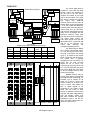
DIGITAL SWITCHERS
2100 SERIES
HIGH PERFORMANCE DIGITAL ROUTING
OPERATORS MANUAL
Includes Module and Frame Information for:
AUDIO
DAS-2144
DAS-2188
DAS-21616
VIDEO
DVS-2144
DVS-2184
DVS-21164
DVM-1616
DVS-1616
SIGMA ELECTRONICS, INC.
P.O. Box 448
1027 COMMERCIAL AVENUE
EAST PETERSBURG, PA 17520-0448
(717) 569-2681
(MAR 04)
2100 DIGITAL
TABLE OF CONTENTS
SECTION 1
OPERATORS MANUAL
Specifications ............................................................................................. Page
Unpacking .................................................................................................. Page
Installation .................................................................................................. Page
Interconnect Wiring .................................................................................... Page
Communication Line Wiring ....................................................................... Page
Control Bus Wiring ..................................................................................... Page
Serial Port Connections .............................................................................. Page
Sync. Reference Input ................................................................................ Page
Redundant Power ...................................................................................... Page
Split Frame ................................................................................................. Page
2100 Series Compatibility ........................................................................... Page
Digital Video General Information .............................................................. Page
DVM-1616 Power ....................................................................................... Page
System Frames .......................................................................................... Page
Video Wiring ............................................................................................... Page
DVS-1616, DVM-1616 ..................................................................... Page
DVS-2144, DVS-2184 and DVS-21164 .............................................. Page
Configuration .............................................................................................. Page
Audio Wiring ............................................................................................... Page
DAS-2144 Module Drawing ........................................................................ Page
DAS-2188 Module Drawing ........................................................................ Page
DAS-21616 Module Drawing ...................................................................... Page
Control Panels ............................................................................................ Page
Multi-Frame Systems ................................................................................. Page
1,2
3
3
3
3
3
3
4
4
4
4
4
4
5
5
5,6
7
7
7
8
9
10
11
11
SECTION 2
SYSTEM CONTROL INTERFACE
SCI-2144 or SCI-1616 for DVS-1616
SECTION 3
CONTROL PANEL OPERATION
System Control Panel ...... ........................................................................ Multiple Pages
SECTION 4
FRAME AND POWER SUPPLY
Modular Frame / Power Supply ............ ................................................... Multiple Pages
SECTION 5 (OPTIONAL)
2100 SERIES OPTIONS
Descriptions for 2100 Series Options ... ................................................... Multiple Pages
2100 DIGITAL
Specifications
DIGITAL VIDEO SWITCH FRAME (DVS -1616, DVM-1616, DVS-2144, DVS-2184, DVS-21164)
DIGITAL VIDEO INPUT:
Input Signal ................... ........................................................ 16, Single-ended, terminated 75Ω
Input Level ..................... ........................................................ SMPTE 259M, 800 mVp-p
Data Rate ...................... ........................................................ 400 Mb/s maximum
Input Cable Length (DVS-1616).............................................. 100 ft. (33 meters) maximum (BELDEN 8281)
(others) .................................................... 50 ft. maximum (BELDEN 8281)
Connectors .................... ........................................................ BNC
DIGITAL VIDEO OUTPUT:
Output Signal ............................... ..........................................
Output Return Loss ................... .............................................
Output To Output Isolation (DVS-1616).... ..............................
(others).........................................
Overshoot ...............................................................................
Connectors .............................................................................
16 Outputs, 800 mVp-p typical, ±10%
15 dB minimum, 5 MHz to 270 MHz
20 dB minimum, 5 MHz to 270 MHz
>45 dB, 5 MHz to 270 MHz
10% maximum of total signal
BNC
GENERAL:
Power Requirements (DVS-1616)........................................... 120 VAC 50/60 Hz, 3A slow blow fuse
........................................ ........................................................ 230 VAC 50/60 Hz, 1.5A slow blow fuse
Power Consumption (DVS-1616)............................................ 13 Watts typical
Operational Temperature ....................................................... 0° to 50° C (+32° to +122° F)
Size (DVS-1616).................................................... ................. 19” W x 1.7” H x 8.2” D (483 x 43.2 x 208 mm)
(DVS-2144 – 1 slot, DVS-2184 – 2 slots, DVS-21164- 4 slots in 2100 system frame)
DIGITAL AUDIO SWITCH MODULE (DAS-2144, DAS-2188, DAS-21616)
Inputs ............................ ........................................................ Differential, Terminated
Input Level ..................... ........................................................ 7 Vp-p maximum
Input Coupling ............... ........................................................ Transformer Coupled, AES-3 1992
Input Impedance ........... ........................................................ 110 Ω
Outputs .......................... ........................................................ Differential
Output Level .................. ........................................................ 7 Vp-p maximum, 3.7 Vp-p typical
Output Impedance ......... ........................................................ 110 Ω
Output to Output Isolation ...................................................... 50 dB minimum
Rise and Fall Time ........ ........................................................ 5nS < tr < 30 nS, 10% to 90% (rise time)
........................................ ........................................................ 5nS < tf < 30 nS, 10% to 90% (fall time)
Serial Data Jitter ............ ........................................................ ± 20 nS Maximum
Input Cable Length ........ ........................................................ 500 ft. maximum (Belden 1800A or equivalent)
Input Common Mode Rejection ............................................. 7 V Peak from DC to 20 kHz
Output Common Mode Noise ................................................ 30 dB Minimum below signal from DC to 6 MHz
Electrical Length ............ ........................................................ 70 nS typical
Connectors .................... ........................................................ 3 Pin Detachable terminals
(continued next page)
2100 Digital Page 1
2100 DIGITAL
Specifications (cont.)
SYSTEM CONTROL INTERFACE MODULE (SCI-2144)
Data Transmission System ....................................................
Serial Port Baud Rate ... ........................................................
Control Levels ............... ........................................................
Communication Line ..... ........................................................
Control Panels ............... ........................................................
Protocol ......................... ........................................................
External Sync Reference .......................................................
Connectors .................... ........................................................
........................................ ........................................................
RS-232 & RS-422
4,800, 9,600, 19,200, 38,400 baud
4
Coaxial, up to 2000 feet
Up to 16 on Comm. Line
Simple ASCII, supports Xon/Xoff
Composite Sync or Blackburst
BNC for Comm. Line and Ext. Sync.
9 Pin “D” for Serial Port
ENVIRONMENTAL
Operational Temperature ....................................................... 0 to 50° C
MECHANICAL
Switch Frame,
Master Control Panel
Single Bus Panels
SS-2100-6 ....................................... 1RU, 1.75” H x 19” W x 9.5” D
SS-2100-16+ ................................... 3RU, 5.25” H x 19” W x 9.5” D
HSY-16S, RC-1640 ....................... 2RU, 3.48” H x 19” W x 1.75” D
HSY-1616, RC-840, SYC-88 ......... 1RU, 1.74” H x 19” W x 1.75” D
HSB-16, SBC-16 ........................... 1RU, 1.74” H x 19” W x 1.75” D
POWER REQUIREMENT
Voltage (Specify at time of order) ...........................................115 VAC or 230 VAC, 50/60 Hz
Power Consumption,
1 RU Frame ................................... 40 W maximum, per frame
3 RU Frame ................................... 100 W maximum, per frame
Supply model / Fuse
SS-2100-6 (120 VAC) ................... APA-2100-6 with WT-2100-6, 2A
SS-2100-6 (230 VAC) ................... APA-2100-6 with WT-2101-6, 2A
SS-2100-16+ (120 VAC) ............... FPS-2100, 2A
SS-2100-16+ (230 VAC) ............... FPS-2101, 1A
Specifications are subject to change without notice.
2100 Digital Page 2
UNPACKING
Inspect your packages and equipment for any damage that may have occurred during shipping. Report any
damages to both Sigma Electronics, Inc. and your shipping company. It is the buyer’s responsibility to file a claim
against the shipping company for cost of repair due to shipping damage.
2100 Series frames are shipped fully loaded within the shipping carton. The frame includes the power supply
and required system modules. Remove the fully loaded frame from the carton. The Operator’s Manual is packed within
the same carton as the frame. Systems configured within the SS-2100-6 frame will contain a wall transformer within the
frame’s carton. Control Panels are shipped in separate cartons. The “Wall Mount” power supply for the control panel is
in the same carton as the control panel.
INSTALLATION
All frames and control panels are intended to be mounted in standard 19” EIA equipment racks. To allow frame
installation into a rack, remove the front door. The SS-2100-16+ frame has two screws used to retain the front panel
during shipping. Remove these screws before attempting to mount the frame into a rack. After mounting the frame into
the rack, the front door is held into place by the ball stud and retaining clip hardware.
Frames are designed for maximum ventilation of normal operational heat production. When feasible leave 1RU
(1.75”) space between frames and other equipment within the rack to assist ventilation.
The Master Frame, in multi-frame systems, is the frame containing the SCI-2144 System Control Interface
Module. The position of the Master Frame may be anywhere within reach of the Control Bus interconnect cable
supplied with the system. Ease of wiring the video and audio Source and destination cables may dictate position of
each frame in multi-framed systems.
INTERCONNECT WIRING
After racking the system, the Video and/or Audio signals must be connected to the router modules.
Connections to the SCI-2144 will allow control of the router. All these connections are located at the rear of the frame.
The following information is a guideline to perform the interconnect wiring.
COMMUNICATIONS LINE WIRING
References to the control panel's communication line are typically abbreviated to COMM Line. All of the control
panels are connected to the System Control Interface SCI-2144 via a coaxial cable. There is one COMM Line BNC
connector on the rear of the Master frame that houses the SCI-2144.
Installation of the Master Control panel in a system requires a 75Ω coaxial cable connection between the
COMM Line BNCs. Connect a coaxial cable between the COMM Line BNC of the SCI-2144 and the COMM connection
BNC on the rear of the control panel. Up to 16 control panels may be added to the COMM Line as system
requirements dictate. Additional panels are added by installing BNC “T” connectors in the coax path. Short coax cables
may be used between the “T” and the new panel or the “T” may be connected directly to the panel. Total coaxial cable
paths are recommended to be within 2000 feet. This coaxial path should NOT be terminated in a 75Ω load.
CONTROL BUS WIRING
Systems with multiple frames use an SLV-2126 module or SLC-2102 kit to transfer the control data between
frames. The control data transfer modules interface via a ribbon cable with 9 Pin D-type connectors. There are two 9
Pin connectors on each card. Either connector may be used. The interface cable supplied is 18 inches in length. Frame
placement within the racks will determine the required length of the bus cable. If the supplied cable does not meet the
site requirements a straight pin to pin 9 Pin Sub-D custom cable may be used.
SERIAL PORT CONNECTIONS
Sigma’s custom RS-232 and RS-422 protocol may be used for external control of the system. This provides a
method to allow computer control, modem control, or other third party control devices to communicate with the SCI2144. The 9 Pin D-type Serial I/O connector is used for this purpose. It is located on the rear of the Master frame on the
SCI-2144 (or SCI-1616 in the DVS-1616). The pin assignment and wiring information is provided in the SCI section of
this manual.
2100 Digital Page 3
SYNC REFERENCE
Sync reference may be applied to the SCI-2144 (or SCI-1616 in the DVS-1616). The routing switcher will
switch during the vertical interval of the reference signal when applied. This signal is applied to the REF IN input on the
rear of the Master frame. In the SCI-2144, the signal is not internally terminated and must be terminated if not looping
through the system. More detailed information is provided in the operator’s manual concerning the differences in the
DVS-1616. This signal can be either Composite Video (1Vp-p) or Composite Sync Pulse (4Vp-p). A jumper, J4, is
provided on the SCI-2144 to properly compensate for the sync-reference signal level. Use the “Comp” position of J4 for
1Vp-p signals (jumper pins 2 and 3) and the “Drive” position for 4Vp-p signals ( jumper pins 1 and 2).
If no signal is present on the REF IN input BNC, the SCI-2144 will execute the switch as soon as it interprets
the command. This may result in non-synchronous switching.
REDUNDANT POWER
The 2100 Series can be configured with a 3RU frame that contains a redundant power supply. The dual power
supplies operate simultaneously. When the 3RU frame contains a redundant power supply the number of card slots
available drops from seventeen to thirteen.
SPLIT FRAME
The SS-2100-16+ frame has a switch in the center of the mother board. The switch provides the option to open
the control bus. The open control bus partitions the frame into two separate switch systems within one frame. An SCI2144 would be required for each system. One side of the frame allows eight card slots the other nine card slots. This
makes the split frame configuration suitable for an 8x8 router of composite video with either mono or stereo audio.
2100 SERIES COMPATIBILITY
The 2100 frames are designed to hold any combination of 2100 Series modules. This allows the frame to
support not only the routing modules but also modules for distribution of various signal formats, sync and pattern
generators and signal transcoders, converters, encoders or decoders.
The flexibility of this frame design allows the router to mix routing modules. Matrix sizes of 4x4 to 16x16 can be
combined under a common control scheme. This also allows balanced and unbalanced audio modules to be combined
within a system. Any 2100 series routing module can be used to configure custom operating systems.
Control panels from any other 2100 Series system can be used to enhance or limit the control capabilities of
multiple control locations. Panels with full X-Y control with or without breakaway capability are available. A panel with
full output status of each output is available. Single bus panels with or without breakaway are also available. The
system has panel addressing capabilities to allow up to sixteen control panels to interface to the router.
DIGITAL VIDEO GENERAL INFORMATION:
The DVS-2144, DVS-2184 and DVS-21164 are full cross-point matrix switchers of 4, 8 or 16 inputs to 4 outputs.
The DVM-1616 or DVS-1616 are full, crosspoint-matrix switchers of 16 inputs to 16 outputs. These units are designed
for Serial Digital signal format SMPTE 259M, CCIR 601 and embedded AES/EBU audio and auxiliary data into digital
video per SMPTE 272M.
The DVM-1616 requires access to a separate SCI-2144 module for system control. The DVS-2144, DVS-2184 and
DVS-21164 would normally receive their control data from the SCI-2144 through the frame motherboard. The control
data generated in the Master frame must be looped to the DVM-1616 via a control-data, looping module, SLV-2126.
The SLV-2126 module consumes a card slot within the Master frame and supplies a data cable that connects to the
DVM-1616.
Data rates of 143, 177, 270 and 360 Mb/s are compatible with this switcher. This refers to data rates for serial
digital video signals of 4fsc NTSC composite, 4fsc PAL composite, and 4:2:2 sampling ratio of component video (NTSC
or PAL format) respectively. Neither unit provides equalization or reclocking circuitry on the inputs and therefore the
input cable lengths should not exceed 100 feet (33 meters) of Belden 8281 or equivalent. If cable lengths exceed the
specifications for the switcher, there are devices available to correct signal degradation for those applications.
POWER: (DVM/DVS-1616 only)
The unit operates from line voltage of 120 VAC or 230 VAC dependent upon the configuration of the power supply
module. Internally the power supply provides a +5 VDC source for the circuit boards contained within the frame. The
PSD-1616 power supply module regulates the bus voltage to +5 VDC via the regulator U1 and associated circuitry.
Circuit protection is provided by fuse F1.
2100 Digital Page 4
FRAME:
The DVM-1616/DVS-1616 system is provided in a frame designed for rack mounting. The 1 RU frame provides
mounting tabs for a standard 19 inch EIA rack cabinet. All components are mounted into the frame from the rear of the
unit. This frame does not provide additional card slots for insertion of other 2100 Series modules.
The DAS-21xx and DVS-21xx modules can reside in some of four different frames provided by Sigma Electronics,
Inc. If these modules are purchased as a component of a system, please refer to the SERIES 2100 FRAMES
Instruction Manual. If the module was purchased separately, an existing frame must be present for proper operation.
Sigma would like to emphasize the fact that any of the Series 2100 Digital modules can be combined in a common
frame with other modules and they must be controlled by a separate control module like the SCI-2144.
♦ The SS-2100-2 frame is designed for desktop applications. This frame provides two (2) slots and can therefore
only accommodate the DVS-2144 or DAS-2144 and the SCI-2144 controller module.
♦ The SS-2100-6, 1RU frame is designed for 19-inch EIA rack installations. This frame can accommodate some of
the DAS-21xx and DVS-21xx modules along with the SCI-2144 controller module. It provides six (6) slots for modules.
♦ The SS-2100-12+ frame provides thirteen (13) slots for modules within 3 RU. A redundant power supplies can be
provided within this frame. This frame can accommodate the DAS-21xx and DVS-21xx modules and the SCI-2144
controller module.
♦ The SS-2100-16+ frame is also available for installations in a 19-inch EIA rack. This frame provides seventeen
(17) slots for modules within 3 RU. This frame can accommodate the DAS-21xx and DVS-21xx modules and its SCI2144 controller module.
VIDEO WIRING:
The video switch inputs are terminating. If the application requires a looping configuration, use a distribution
amplifier on the input signal to send the source signal to multiple devices. This provides the video source with proper
75Ω termination.
Simply connect the source video cables to corresponding input BNCs on the rear of the video routing frame.
Refer to the sections below to review drawings for input and output layout. Sigma Electronics’ connector layout is
designed to economically maximize performance. The source video cable connects to the video input on the rear panel.
The outputs of the video router connect to destination devices. Some devices may be both source and destination
devices. Connect the source signal from the device’s output to the routers input. The destination's input receives a
signal from the router’s output.
DVS-1616 and DVM-1616
Connectors for wiring of source signals and destination devices are located on the rear panel. The inputs, outputs,
Comm. bus and sync reference input use BNCs. A 9 pin D connector is provided for the SCI RS-232/422 interface on
the DVS-1616 model. The DVM-1616 has a 9 pin D connector for control data from a master frame.
SERIAL DIGITAL VIDEO INPUT: The BNC connectors to the left of center on the rear panel provide the 16 Serial
Digital video inputs. Each BNC is a 75Ω terminated connection.
SERIAL DIGITAL VIDEO OUTPUT: The BNC connectors to the right of center on the rear panel provide the 16
Serial Digital video outputs. Each output utilized requires a 75Ω terminated destination. The unused outputs do not
require a 75Ω load.
SYSTEM CONTROL: There are several methods of configuring system control. Take note that the DVS-1616 is
complete with an SCI. The DVM-1616 does not include an SCI and therefore requires control data from a master
frame.
The DVS-1616 has a BNC labeled “COMM” which is used to connect a coaxial cable to a remote control panel.
Multiple control panels are attached via BNC ‘T’ connectors at each panel to perform a looping network. Total cable
distance can be up to 2000 feet. The system can support as many as sixteen control panels.
The DVS-1616 includes the SCI-1616 which provides a 9 pin D connector for external control of RS-232/RS-422
protocol. This system uses the SCI-1616 module which operates from SCI-2144 protocol which is standard for the
2100 Series. The SCI is located on the rear far left side of the frame.
The DVM-1616 does not include an SCI-1616 module or control panel and therefore is dependent upon a
master frame for control. The control data from the master frame is provided by an optional SLV-2126. This is a single
slot module which mounts in the master frame. Along with the module is an interface cable with 9 pin D connectors.
The control data enters the DVM-1616 at the 9 pin D connector on the power supply module located on the right side
on the rear of the frame. There is no direct connection for control on the DVM-1616. All control communications must
be connected to the master frame. Note that the DVM-1616 requires a control scheme of 16 inputs to 16 outputs. If the
master frame is configured in a smaller matrix the SCI in the master frame will need to be reconfigured for 16x16. This
is achieved by the DIP switch selection on the SCI within the master frame. Refer to the protocol section of the
operation manual for the master frame.
2100 Digital Page 5
DVS-1616 and DVM-1616
SERIES 2100
DVS-1616
SIGMA ELECTRONICS, INC.
DVS-1616 FRONT PANEL
SCI
1616
CONTROL BUS
CLEAR
2
4
6
SERIAL I/O
1
REF IN
S1
3
8
10
INPUTS
7
9
5
12
11
14
13
16
1
3
5
2
15
7
4
9
11
OUTPUT
8S
10
6
13
12
15
14
16
FUSE
3.0 AMP
SLO-BLO
120
VAC
COMM
System Control
Interface
Serial Digital
Serial Digital
Video Input
Video Output
DVS-1616 REAR PANEL CONNECTIONS
Figure 1
SERIES 2100
Power Supply
DVS-1616
SIGMA ELECTRONICS, INC.
DVM-1616 FRONT PANEL
2
1
4
3
6
5
8
INPUTS
7
9
10
12
11
14
13
16
15
1
3
2
5
4
7
6
9
11
OUTPUT
8S
10
13
12
Serial Digital
Serial Digital
Video Input
Video Output
DVM-1616 REAR PANEL CONNECTIONS
Figure 2
2100 Digital Page 6
CONTROL BUS
15
14
16
FUSE
3.0 AMP
SLO-BLO
120
VAC
Power Supply
& Control Bus
DVS-2144, DVS-2184 AND DVS-21164
The DVS-2144 is a four-input to four-output video switch, the DVS-2184 is an eight input to four output video
switch and the DVS-21164 is a sixteen input to four output video switch. The inputs; arranged in ascending numerical
order, top to bottom; are on the left side of the rear panel. The outputs 1 to 4 are located to the right of the inputs.
DVS-2144, DVS-2184 and DVS-21164 REAR PANEL CONNECTIONS
CONFIGURATION:
The DVS-2144, DVS-2184 and DVS-21164 all slide into the 2100 system frames from the rear. The DVS/DVM1616 has a motherboard that slides into its 1RU frame from the rear. This PCB contains all the input, crosspoint and
output driver circuitry. The following information is provided for custom configuration of the digital video control bus. The
factory settings provide control of the digital video frame normally on level four.
The jumpers provided on the modules are set at factory default conditions. The main module should not require
any reconfiguration for normal operation. A soldered wire jumper is provided for control level selection. In typical
systems, the main video is set to Level 1 and audio is set to Level 2. Therefore, the following defaults are used.
LEVEL JUMPER: This is a soldered wire jumper located near the front edge of the printed circuit board. There are
five holes labeled “C or W2A”, “1”, “2”, “3”, and ”4” to the right of the silk screen label of “LEVELS”.
Model: DVM-1616, Jumper configured for level 4 control (“C” and “4” positions jumped). Typically, this model
functions as an add-on frame to a master system. The master frame may already have level 1 video and/or level 2
audio modules.
OUTPUTS JUMPER (DVS/DVM-1616 ONLY): Do NOT reconfigure this jumper. The DVS/DVM-1616 must use the
“1-16” position.
AUDIO WIRING
Differential Audio connections are provided via 3 position detachable terminal blocks. There is an individual
connector assigned for each input and output. Where audio signals need to be bridged from the audio switch module to
another device, the use of digital, audio distribution amplifiers is recommended.
Refer to the digital, audio module drawings that follow for locations of the input and output connectors. Each
detachable connector is marked for polarity and keyed for insertion of the plug into the receiving header.
2100 Digital Page 7
DAS-2144
Module Block Diagram
DAS-2144
W1 - Level Jumper
J6
Logic IC
Control Bus
CROSS-POINTS
Differential Receivers
Differential Drivers
INPUTS 1 TO 4
The 4x4 digital audio switcher is
provided as a one-slot width module. The
rear panel has inputs on the top half and
outputs on the bottom half of the module.
The main PCB, also identified as DAS2144, is directly attached to the rear
panel. This card plugs into the frame that
supplies power and control data.
The Level jumper, W1, sets the
control level. The control level is typically
factory-set to Level 2 for audio. The input
group is set by the position of jumper J6.
The default setting is 1-8. The output
group on this card is set at the factory
and should not be changed.
OUTPUTS 1 TO 4
W1 Settings
Control Level
Control
Level #
1
2
3
4
W1
ORIGIN
C
C
C
C
W1
DEST.
1
2
3
4
J6 Settings
Input Group
Group
Level
1-8
9 - 16
J6
Position
2-3
1-2
Rear View
2100 Digital Page 8
DAS-2188
Module Block Diagram
DAO-108
DAI-108
P1
J5 / J6
S1 Level /
Matrix / Group
Logic IC
Control Bus
CROSS-POINTS
Differential Receivers
Differential Drivers
INPUTS 1 TO 8
OUTPUTS 1 TO 8
S1 Settings
Output Group / Matrix / Control Level
S1-1
Matrix S1-2
Control
Level #
ON
8x8
ON
1
OFF
16x8
OFF
2
3
4
Output
Group
1 to 8
9 to 16
S1-3
S1-4
ON
ON
OFF
OFF
ON
OFF
ON
OFF
DAS
2188
Inputs
+
C
-
+
C
-
Outputs
+
C
-
+
C
-
1
1
2
+
C
-
+
C
-
2
+
C
-
+
C
-
3
3
4
+
C
-
+
C
-
+
C
-
+
C
-
4
+
C
-
+
C
-
+
C
-
+
C
-
5
4
3
2
1
ON
5
6
6
7
7
8
Inputs
S1
8
Outputs
DAS
2188
Rear View
OUTPUT INPUT
Front View
2100 Digital Page 9
The 8x8 digital audio is provided
as a two card slot width module. The rear
panel has inputs on the left half of the
module. The input card, DAI-108, is
attached to the input connector panel.
Outputs are located on the right half of
the rear panel. An output card DAO-108
is attached to the back panel. This card
plugs into the frame that supplies power
and control data.
The Level / Group switch, S1,
sets the control level as well as the matrix
configuration and output group. The
control level is typically factory set to
Level 2 for audio. The input group is
defaulted to 1-8. The output group on this
card should be set to 1-8. The matrix
setting should be set to 8x8 for this
module. Refer to the S1 switch chart to
customize the settings for special
applications.
DAS-21616
DAO-916
Module Block Diagram
S1
Level/Group
S1
Level/Group
Logic
Logic
Control
Bus
DAO-108
Control
Bus
J7
U4
Crosspoints
U4 Crosspoints
DAI-916
Output Drivers
Output Drivers
DAI-108
P1
INPUTS 9-16
OUTPUTS 9-16
OUTPUTS 1-8
INPUTS 1-8
S1 Settings
Output Group, Matrix Size and Control Level
S1-1
Matrix
S1-2
Control
S1-3
Size
Level
ON
8x8
ON
1
ON
OFF
16x16
OFF
2
ON
3
OFF
4
OFF
Output
Group
1-8
9-16
Inputs
Inputs
+
C
-
+
C
-
+
C
-
+
C
-
+
C
-
+
C
-
+
C
-
+
C
-
+
C
-
9
+
C
-
+
C
-
+
C
-
+
C
-
+
C
-
+
C
-
+
C
-
C
-
+
C
-
+
C
-
+
C
-
+
C
-
+
C
-
+
C
-
+
C
-
-
+
C
-
+
C
-
+
C
-
+
C
-
+
C
-
+
C
-
9
10
11
12
ON
S1
4
3
2
1
ON
14
7
8
S1
4
3
2
1
13
6
8
Inputs
C
5
7
16
+
4
6
15
-
3
5
14
C
2
4
13
+
1
3
12
Inputs
+
2
11
ON
OFF
ON
OFF
Outputs Outputs
1
10
S1-4
15
16
Outputs Outputs
DAS
1616
Rear View
OUTPUT OUTPUT INPUT INPUT
Front View
2100 Digital Page 10
The 16x16 digital audio is
provided in a four card slot width
module. Inputs are provided on
the left side of the rear panel.
Outputs are located on the right
side of the rear panel. Four cards
are used to process the signals.
The output card, DAO-108
receives power from the frame to
support input circuitry and outputs
1 to 8. The output card DAO-916
receives power from the frame for
output group 9 to 16. The DAO108 receives control data from the
frame for it’s crosspoints and the
DAO-916 receives control data
from the frame for its crosspoints.
The output cards receive the
audio input signals from the two
input cards via P1, on the DAI-108
and P1 on the DAI-916. The
output
card
performs
the
crosspoint switching function.
The Output Group / Matrix
Size / Control Level Select switch,
S1, sets the logical control level,
the size of the matrix and output
group. It is located on the output
cards (DAO-108 and DAO-916).
The control level is typically
defaulted to Level 2 for audio. The
matrix size on both modules
should be set to 16x16. The
output group select should be set
to 1-8 for the DAO-108 and group
9-16 for the DAO-916 card. Refer
to the S1 Settings chart for other
control level settings.
Multiple modules may be
present if the system is configured
for multiple levels of switching. For
example: Use a module for all
audio on a level 2 control and
another module for all audio on a
level 4 control. This allows two
sets of digital signals to be
controlled by one master control
panel. Set the levels of each
module to different control levels
and they will switch independently
from one another. Please note
that video modules are typically
defaulted to level 1. Do not use
level 1 for audio unless audio is to
follow the video source.
Control Panels
The 2100 Digital Series routers will function with any of the 2100 Series Control Panels.
The control panels have address switches that allow addressing from one (1) through sixteen (16). There may be
as many as sixteen panels on each router system. The panels may be a mixture of Full X-Y master control panels or
Single Bus panels that control only one selected output. Most panels offer the selection to operate in either a Preset or
Auto-Take mode. The Preset mode allows the user to select a source and desired destination and hold that “preset”
until the TAKE button is depressed. The AutoTake mode will automatically perform the “take” function when the
destination number is selected. Some panels allow the user to select the mode of operation via a switch on the rear of
the control panel housing. Other streamlined panels provide autotake mode only.
Refer to the Control Panel section of this manual for specific operation information for the supplied control panel(s).
The required control panel interface cable is 75-ohm coax. The total length of the cable should not exceed 2000
feet. If multiple panels are to be connected to the system, BNC ‘T’ connectors should be used to split the
communication (COMM) line. The COMM line can be configured in either a daisy chain, star or mixture of both
configurations. Cable lengths should be kept to a minimum for best system operation. No 75-ohm termination is
required
All control panels will be allowed the same priority on the router system. There are no user level priorities available
to limit the control of any given panel. Some control panels do allow the setting of control levels that would allow a panel
to restrict control of video only or audio only.
Multi-Frame Systems
When system configuration requires more than one frame to house the modules, the control data must be looped
from the master frame, which contains the SCI-2144, to any additional frames. The control data contains the Control
Level and Crosspoint information generated by the SCI-2144. The transfer of control data between frames requires an
interface module in each frame with a flexible ribbon cable attached to each module.
When two frames are in a routing system the SLC-2102 kit is required. This kit contains two modules, one for each
frame, and an interface cable. The cable is typically 18 inches as supplied by the factory. Longer cables may be used
when the application does not allow the frames to be mounted together in the rack mount frame. The 9 Pin D
connectors used on this cable are wired pin to pin. The modules supplied with the SLC-2102 have two connectors
each. Either connector may be used. The alternative connector will be used for communicating to additional frames.
If more than two frames are used the additional frames require only the SLV-2126 kit. This kit contains one single
card slot module and a cable. The module mounts into the frame with the cable attached between the module and an
available 9 Pin D connector on the SLV-2126 located in the master frame.
If 2100 Series frames are used only for modules other than routing, there is not a need to interface the frames. This
applies to frames that house analog or digital distribution amplifiers, transcoders, encoders, decoders and sync
generator modules. The control-data looping kits are only required when multiple frames house routing modules.
2100 Digital Page 11
REV 5
Specifications and performance subject to change without notice.
MAR 04
2100 Series Digital Switchers