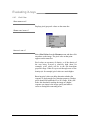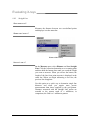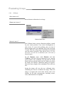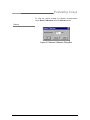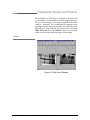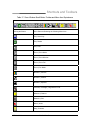
1
CDR User Guide Schick Technologies, Inc. 30-00 47th Avenue Long Island City, NY 11101 (718) 937-5765 (718) 937-5962 (fax) PART NUMBER B1051001 REV. B Copyright 2001 by Schick Technologies, Inc. All Rights Reserved Many of the designations used by manufacturers and sellers to distinguish their products are claimed as trademarks. Where those designations appear in this document, and Schick Technologies, Inc. was aware of a trademark claim, the designations have been printed in caps or initial caps. Part Number B1051001 Rev. B September 11 2001 ! Printed in the United States of America This document was originally prepared in English Contents 1. THE BASICS ....................................................................................................................................... 1 2. CDR SYSTEM..................................................................................................................................... 3 2.1 2.2 2.3 2.4 2.5 2.6 2.7 2.8 CDR SENSORS ....................................................................................................................................... 3 SENSOR CARE ........................................................................................................................................ 3 ACCESSORIES ......................................................................................................................................... 4 PERIPHERALS ......................................................................................................................................... 4 HARDWARE AND SOFTWARE .................................................................................................................. 5 OTHER CDR EQUIPMENT ....................................................................................................................... 5 ABOUT THIS MANUAL ............................................................................................................................ 5 TEXT CONVENTIONS IN THIS MANUAL ................................................................................................... 6 3. INSTALLING CDR ............................................................................................................................ 7 3.1 3.2 3.3 3.4 INSTALLING CDR SOFTWARE ................................................................................................................ 7 INSTALLING SENSOR CALIBRATION FILE................................................................................................ 8 WHERE IMAGES ARE STORED ................................................................................................................. 8 NETWORKING......................................................................................................................................... 8 3.4.1 Dedicated Server Networks........................................................................................................ 8 3.4.2 Non-Dedicated Server Networks................................................................................................ 9 4. CDR FUNDAMENTALS.................................................................................................................. 11 4.1 4.2 4.3 4.4 SETUP................................................................................................................................................... 11 ACQUIRE .............................................................................................................................................. 11 EVALUATE ........................................................................................................................................... 11 PRINT AND STORE ................................................................................................................................ 12 5. CDR WINDOWS............................................................................................................................... 13 5.1 5.2 5.3 5.4 5.5 EXAM WINDOW ................................................................................................................................... 14 QUICKZOOM DISPLAY.......................................................................................................................... 15 ZOOM WINDOW ................................................................................................................................... 16 MENUS ................................................................................................................................................. 17 TOOLBARS ........................................................................................................................................... 17 5.5.1 Normal Size Toolbars............................................................................................................... 18 5.5.2 Small Button Toolbars ............................................................................................................. 18 TOOLTIPS, MENU ITEM TIPS, AND STATUS MESSAGES ........................................................................ 19 5.6.1 ToolTips ................................................................................................................................... 19 5.6.2 Menu Item Tips......................................................................................................................... 19 5.6.3 Status Messages ....................................................................................................................... 19 5.6 6. EXAMS .............................................................................................................................................. 21 6.1 6.2 NEW ..................................................................................................................................................... 21 SERIES .................................................................................................................................................. 22 6.2.1 Editing a Series (Current exam)............................................................................................... 23 6.2.2 Editing a Series (Current and / or New exam) ......................................................................... 25 6.2.3 Creating a New Standard Series .............................................................................................. 27 6.2.4 Creating a New Grid Series ..................................................................................................... 29 6.2.5 Creating a New Video Series ................................................................................................... 31 6.2.6 Creating a New Panoramic Series ........................................................................................... 33 OPEN .................................................................................................................................................... 35 SAVE .................................................................................................................................................... 37 PATIENT HISTORY ................................................................................................................................ 38 CLOSE .................................................................................................................................................. 40 PATIENT INFORMATION ........................................................................................................................ 41 EXAM COMMENTS................................................................................................................................ 43 6.3 6.4 6.5 6.6 6.7 6.8 CDR User Guide B1051001 Rev. B i 7. ACQUIRING X-RAYS ..................................................................................................................... 45 7.1 7.2 7.3 7.4 7.5 7.6 7.7 SELECTING THE TARGET FRAME .......................................................................................................... 45 ACQUIRING IMAGES ............................................................................................................................. 45 AUTO-ACQUIRING IMAGES (AUTOTAKE™)......................................................................................... 45 ACCEPTING, RETAKING, AND REJECTING X-RAYS ............................................................................... 46 POSITIONING CDR SENSORS ................................................................................................................ 47 SENSOR ORIENTATION ......................................................................................................................... 47 GETTING THE BEST IMAGE QUALITY ................................................................................................... 49 7.7.1 Calibration ............................................................................................................................... 49 7.7.2 Exposure .................................................................................................................................. 49 7.7.3 Placement................................................................................................................................. 50 8. EVALUATING X-RAYS.................................................................................................................. 53 8.1 8.2 8.3 8.4 8.11 8.12 ZOOM ................................................................................................................................................... 55 ZOOM AREA ......................................................................................................................................... 56 PAN AREA ............................................................................................................................................ 57 ENHANCE ............................................................................................................................................. 59 8.4.1 Colorize.................................................................................................................................... 60 8.4.2 Positive..................................................................................................................................... 61 8.4.3 Sharpen .................................................................................................................................... 62 8.4.4 Spot Remover ........................................................................................................................... 63 8.4.5 Equalize.................................................................................................................................... 65 8.4.6 Emboss ..................................................................................................................................... 66 8.4.7 Highlight .................................................................................................................................. 67 NOTES .................................................................................................................................................. 69 8.5.1 Adding Notes............................................................................................................................ 70 8.5.2 Editing/Deleting Notes ............................................................................................................. 72 8.5.3 Note Shortcuts .......................................................................................................................... 74 8.5.4 Global Notes ............................................................................................................................ 76 CONTRAST ........................................................................................................................................... 78 REORIENT............................................................................................................................................. 79 FLASHLIGHT ......................................................................................................................................... 81 MEASURE ............................................................................................................................................. 82 8.9.1 Exposure Advisor™ ................................................................................................................. 83 8.9.2 Pixel Value ............................................................................................................................... 84 8.9.3 Straight Line............................................................................................................................. 86 8.9.4 Calibrate .................................................................................................................................. 88 8.9.5 Multiple Lines and Angles........................................................................................................ 90 8.9.6 Grid .......................................................................................................................................... 92 8.9.7 Histograms ............................................................................................................................... 93 FILE...................................................................................................................................................... 95 8.10.1 Save Xray ................................................................................................................................. 95 8.10.2 Export....................................................................................................................................... 96 8.10.3 Delete ....................................................................................................................................... 97 8.10.4 Retake....................................................................................................................................... 98 8.10.5 Print ......................................................................................................................................... 99 8.10.6 Close Window ........................................................................................................................ 100 UNDO/REDO/LIST ALL CHANGES....................................................................................................... 101 IMPORT .............................................................................................................................................. 102 9. ARRANGING IMAGES................................................................................................................. 103 9.1 9.2 COPY/PASTE....................................................................................................................................... 103 SWAP ................................................................................................................................................. 104 10. MAILING IMAGES ....................................................................................................................... 105 10.1 10.2 10.3 10.4 SENDING MAIL ................................................................................................................................... 106 RECEIVING MAIL................................................................................................................................ 109 SOME NOTES ON CONFIGURING MAIL ................................................................................................ 111 GENERATING ATTACHMENTS ONLY................................................................................................... 112 8.5 8.6 8.7 8.8 8.9 8.10 ii B1051001 Rev. B CDR User Guide 10.5 NOTE FOR RECEIVING CDR EXAMS FROM AOL USERS..................................................................... 112 11. PRINTING....................................................................................................................................... 113 11.1 11.2 11.3 11.4 SINGLE IMAGE.................................................................................................................................... 114 MULTIPLE IMAGES (EXAMS) .............................................................................................................. 115 PRINTERS ........................................................................................................................................... 116 REPORTS ............................................................................................................................................ 117 11.4.1 Endodontic Report ................................................................................................................. 117 11.4.2 Periodontic Report................................................................................................................. 119 11.4.3 Word Template Report ........................................................................................................... 121 12. DISPLAYING IMAGES AND EXAMS........................................................................................ 123 12.1 12.2 12.3 MULTIPLE IMAGES ............................................................................................................................. 123 12.1.1 Tiling ...................................................................................................................................... 124 12.1.2 Stacking.................................................................................................................................. 126 12.1.3 Image History......................................................................................................................... 127 MULTIPLE EXAMS .............................................................................................................................. 128 HIDING EXAM WINDOW AREAS ......................................................................................................... 129 13. ADVANCED TOPICS .................................................................................................................... 131 13.1 13.3 13.4 13.5 13.6 FILE MAINTENANCE ........................................................................................................................... 131 13.1.1 Copy In/Out............................................................................................................................ 131 13.1.2 Delete ..................................................................................................................................... 133 13.1.3 Historical Compression ......................................................................................................... 135 13.1.4 Setup CD-ROM ...................................................................................................................... 137 13.1.5 Rebuild Database................................................................................................................... 138 SYSTEM MAINTENANCE ..................................................................................................................... 139 13.2.1 Sensor Information................................................................................................................. 139 13.2.2 System Configuration ............................................................................................................. 141 13.2.3 Setup Dentist Information ...................................................................................................... 144 13.2.4 Define Note Short-Cuts .......................................................................................................... 145 13.2.5 Set Background Color and Set Font....................................................................................... 146 13.2.6 Set TWAIN Source.................................................................................................................. 147 CDR.INI FILE .................................................................................................................................... 149 CDR OPTIONS.................................................................................................................................... 153 CDR DIAGNOSTIC UTILITY ................................................................................................................ 155 UPGRADING CDR USB REMOTE MODULES ...................................................................................... 157 14. SHORTCUTS AND TOOLBAR BUTTONS ................................................................................ 131 14.1 14.2 SHORTCUTS ........................................................................................................................................ 159 TOOLBAR BUTTONS ........................................................................................................................... 162 13.2 List of Figures FIGURE 1. EXAM WINDOW ............................................................................................................................... 14 FIGURE 2. QUICKZOOM DISPLAY .....................................................................................................................15 FIGURE 3. ZOOM WINDOW ............................................................................................................................... 16 FIGURE 4. SAMPLE PULL-DOWN MENU ............................................................................................................17 FIGURE 5. EXAM WINDOW TOOLBAR ...............................................................................................................18 FIGURE 6. ZOOM WINDOW TOOLBAR ...............................................................................................................18 FIGURE 7. EXAM WINDOW SMALL BUTTON TOOLBAR .....................................................................................18 FIGURE 8. ZOOM WINDOW SMALL BUTTON TOOLBAR .....................................................................................18 FIGURE 9. ACCEPTING/REJECTING IMAGE DISPLAY .........................................................................................46 FIGURE 10. ACCEPTING IMAGE ON ACQUISITION DISPLAY ...............................................................................46 FIGURE 11. SOME ALIGNMENT EFFECTS ON IMAGE QUALITY ..........................................................................51 FIGURE 12. USING THE ZOOM FEATURE ...........................................................................................................55 FIGURE 13. USING THE POSITIVE FEATURE ......................................................................................................61 FIGURE 14. USING THE SHARPEN FEATURE ......................................................................................................62 CDR User Guide B1051001 Rev. B iii FIGURE 15. USING THE SPOT REMOVER FEATURE ............................................................................................64 FIGURE 16. USING THE EMBOSS FEATURE ........................................................................................................66 FIGURE 17. USING THE HIGHLIGHT FEATURE ...................................................................................................68 FIGURE 18. INSERT NOTE DIALOG BOX ............................................................................................................71 FIGURE 19. EDITING AND DELETING NOTES .....................................................................................................73 FIGURE 20. NOTE SHORTCUT DIALOG BOXES ..................................................................................................75 FIGURE 21. LOCATION OF GLOBAL NOTES .......................................................................................................77 FIGURE 22. USING THE REORIENT FEATURE .....................................................................................................80 FIGURE 23. USING THE FLASHLIGHT FEATURE .................................................................................................82 FIGURE 24. USING THE PIXEL VALUE FEATURE ...............................................................................................85 FIGURE 25. USING THE STRAIGHT LINE FEATURE ............................................................................................87 FIGURE 26. DISTANCE CALIBRATION DIALOG BOX ..........................................................................................89 FIGURE 27. USING MULTIPLE LINE FEATURE ...................................................................................................91 FIGURE 28. USING MULTIPLE LINE FEATURE (ANGLES SHOWN)......................................................................91 FIGURE 29. GRID PATTERN ............................................................................................................................... 92 FIGURE 30. VERTICAL HISTOGRAM SAMPLE ....................................................................................................94 FIGURE 31. RETAKE COMPARISON DISPLAY .....................................................................................................98 FIGURE 32. UNDO/REDO MENU AND DIALOG BOX.........................................................................................101 FIGURE 33. ENDODONTIC REPORT ..................................................................................................................118 FIGURE 34. PERIODONTIC REPORT..................................................................................................................120 FIGURE 35. MENU LIST OF IMAGES AND EXAMS ............................................................................................123 FIGURE 36. TILED ZOOM WINDOWS ...............................................................................................................125 FIGURE 37. TILED EXAMS IN EXAM WINDOW ................................................................................................128 FIGURE 38. CASCADED EXAMS IN EXAM WINDOW ........................................................................................128 FIGURE 39. EXPLODED EXAM IN EXAM WINDOW...........................................................................................129 FIGURE 40. HIDE ELEMENTS MENU ITEM .......................................................................................................129 FIGURE 41. COPY IN AND COPY OUT DIALOG BOXES.....................................................................................132 FIGURE 42. HISTORICAL COMPRESSION DIALOG BOX ....................................................................................136 FIGURE 43. SENSOR DIALOG BOX ..................................................................................................................140 FIGURE 44. SYSTEM CONFIGURATION DIALOG BOX .......................................................................................142 FIGURE 45. DENTIST INFORMATION DIALOG BOX ..........................................................................................145 FIGURE 46. SELECT TWAIN SOURCE ............................................................................................................148 FIGURE 47. SAMPLE CDR.INI FILE ................................................................................................................152 FIGURE 48. CDR OPTIONS DIALOG BOX ........................................................................................................154 FIGURE 49. ONE OF THE CDR DIAGNOSTIC UTILITY SCREENS .......................................................................156 FIGURE 50. UPGRADING REMOTE MODULE SCREEN ......................................................................................158 List of Tables TABLE 1. CDR SENSOR CARE INSTRUCTIONS ....................................................................................................3 TABLE 2. CDR SENSOR CABLE CARE INSTRUCTIONS.........................................................................................3 TABLE 3. INSERTING BITE TAB AND COVERALL SENSOR SHEATH ......................................................................4 TABLE 4. CDR PROGRAM GROUP ......................................................................................................................7 TABLE 5. CDR SENSOR TO IMAGE ORIENTATION .............................................................................................48 TABLE 6. OPENING AN IMAGE IN A ZOOM WINDOW .........................................................................................53 TABLE 7. EXITING THE ZOOM WINDOW ...........................................................................................................53 TABLE 8. SAVING CHANGES IN THE ZOOM WINDOW ........................................................................................54 TABLE 9. PAN MODE KEYSTROKES ..................................................................................................................58 TABLE 10. PRINTERS COMPATIBLE WITH CDR...............................................................................................116 TABLE 11. CDR QUESTIONS AT THE SYSTEM CONFIGURATION DIALOG BOX ................................................143 TABLE 12. EXAM WINDOW SHORTCUT KEYS .................................................................................................159 TABLE 13. ZOOM WINDOW SHORTCUT KEYS .................................................................................................160 TABLE 14. EXAM WINDOW TOOLBAR BUTTON AND MENU ITEM EQUIVALENCE ...........................................162 TABLE 15. ZOOM WINDOW TOOLBAR BUTTON AND MENU ITEM EQUIVALENCE ...........................................164 TABLE 16. EXAM WINDOW SMALL BUTTON TOOLBAR AND MENU ITEM EQUIVALENCE ...............................166 TABLE 17. ZOOM WINDOW SMALL BUTTON TOOLBAR AND MENU ITEM EQUIVALENCE ...............................167 iv B1051001 Rev. B CDR User Guide Getting Help In the event you require technical support related to your new CDR system, please contact your local distributor (Patterson Dental Supply, Inc. in the United States), or the authorized international dealer for Schick Technologies products in your country or region. Customers who have purchased products directly from Schick Technologies can reach us at the following number: 1-877-SCHICK-Help (1-877-724-4254). Before contacting us for technical support, there are a few things you can do to help us expedite your call. Below is a short list of information our support personnel will ask you, so having this information available before you call will help us resolve your questions more efficiently. • What Windows operating system are you running (Windows 98, NT, 2000, etc.)? • What numbered version of CDR software are you running (2.6, 2.5, etc). Is it single- or multi-user? • If your CDR system is networked, does it use a dedicated server (server stores images but is not used for acquisition), a non-dedicated server (server used for image storage and acquisition), or peer-to-peer (no central server)? Depending on the nature of your call, we may also ask you to check the communication status between your CDR hardware and software. To do this, make sure your sensor and Remote Module are connected, and the cable connection between the Remote Module and your computer is secure. Start CDR, open the System menu, and then click on Sensor and Sensor Info. If you are using a CDR 2000 USB system, three "Unknowns" in the Sensor Info dialog box often point to an incorrect or corrupt device driver. You may have also received white images in CDR software even though the steps and duration for taking X-rays appeared normal. In this case, use the Diagnostic Utility provided with CDR to reload the USB driver (Windows 98 systems) and to verify other potential problem areas. It is also important to make sure you have the correct firmware installed in your Remote Module for the version of CDR software you are running. (Make sure your sensor, Remote Module, and USB cable are connected when checking this information.) The firmware version number can be verified in the Help menu by clicking on About CDR. Starting with CDR 2.6, you will be automatically prompted in the event there is a mismatch between CDR software and firmware. You can also verify the firmware version manually by clicking the Windows Start menu, Programs, CDR, Upgrade CDR 2000 Remote, and then at the Start screen click the Verify menu. CDR User Guide B1051001 Rev. B v (This page intentionally left blank) vi B1051001 Rev. B CDR User Guide 1. The Basics Follow the steps below to take an X-ray using CDR. For additional details on acquiring images (manual acquire and AutoTake), refer to Section 7. STEP 1 Start CDR from the Windows Start button or by clicking on the desktop shortcut to CDR. STEP 2 A. In the CDR exam window, click > File > New, or click the New Exam button. B. In the Patient Information dialog box, enter the appropriate information and select the series. C. Click OK. STEP 3 A. Place the sensor in the holder, and then place the sheath over sensor and holder. Place the sensor in the patient’s mouth with the flat side facing the X-ray tube. B. Check the X-ray source exposure setting. The proper setting on the X-ray source depends on several factors, among them, the type of tube, the anatomy of the patient, and the location of the sensor in the oral cavity. STEP 4 CDR USB Systems with AutoTake — The first empty target frame is preselected and flashes green (default setting). Skip ahead to Step 6. All other CDR Systems — Select an empty target frame that matches the sensor’s location in the patient’s mouth. When the frame is highlighted, click on it again. If the system is equipped with a footpedal, press the amber pedal. CDR User Guide B1051001 Rev. B 1 The Basics STEP 5 The CDR system is now in image acquisition mode. A “Please Wait” message may appear momentarily. STEP 6 CDR USB Systems with AutoTake — Activate the X-ray source. “Reading Image from Sensor” appears on the screen momentarily. All other CDR Systems — Activate the X-ray source when “Waiting to take X-ray” appears. STEP 7 CDR USB Systems with AutoTake — When acquisition is complete, the image appears in the zoom window. All other CDR Systems — If AUTO_ACCEPT=YES, the image appears immediately in the zoom window. If AUTO_ACCEPT=NO, the Accept/Reject dialog box appears. STEP 8 CDR USB Systems with AutoTake — CDR advances to the next empty frame in the series automatically. To take another X-ray, repeat this procedure starting at Step 6. All other CDR Systems — Close the zoom window. The exam window is displayed again with the image. To take another X-ray, repeat this procedure starting at Step 4. 2 B1051001 Rev. B CDR User Guide 2. CDR System Computed Dental Radiography (CDR®) is an electronic diagnostic system that acquires, displays, prints, and stores digital X-rays and video images. This section provides a general system overview and describes the conventions used in this manual. In the sections that follow, all of the features of the CDR software program are described, up to and including CDR version 2.5. More detail about new software features can also be found in the "Using New Features" documents, located after the CDR Supplements tab of this binder. 2.1 CDR Sensors CDR sensors are available in three sizes (0, 1, and 2). Size 0 is suitable for children, and Sizes 1 and 2 are appropriate for adult patients. The sensor is an electronic device, and although it has been designed for durability and long-term reliability, it should be handled with care. 2.2 Sensor Care Your CDR sensor is designed and tested to withstand years of daily use. To help ensure it provides reliable service, refer to the following tables for guidelines on proper care. Table 1. CDR Sensor Care Instructions DO DON’T Wipe down Sensor with sterile solution Don't soak Sensor or its edge-card connector in sterile solution and don't autoclave Sensor Use our bite holders, tabs, and sterile sheaths with Sensor Don't clamp Sensor or cable with a hemostat Table 2. CDR Sensor Cable Care Instructions DO DON'T Carefully uncoil Sensor cable by letting edgecard hang down while holding Sensor. Carefully remove all tangles and sharp bends and make sure cable is completely uncoiled before using Sensor. Don't create sharp bends and knots when untangling Sensor cable. When completely uncoiled, don't allow Sensor cable to become tangled during use. Disconnect Sensor from Remote Module by grasping edge-card and pulling it gently from Remote Don’t disconnect Sensor from Remote Module by pulling on Sensor cable Remove Rinn holder from Sensor by grasping Sensor and gently sliding holder off Sensor Don't pull on Sensor cable to remove Rinn holder After using your Sensor, gently coil Sensor cable and place Sensor in its protective case Don't hang Sensor by its cable, or let Sensor cable dangle near the floor where it can become tangled or near a cabinet drawer where it can be caught or crimped CDR User Guide B1051001 Rev. B 3 Evaluating X-rays 2.3 Accessories There are several different holders available for the CDR sensors, including Rinncompatible, endodontic and pedodontic holders. There is also a modified “Snap-a-Ray” holder and a variety of bite tabs as well. Finally, there are holders that clip on the sensor and have tabs that can be gripped with a hemostat. CAUTION – Never clamp the sensor package or cable with a hemostat or an unmodified “Snap-a-Ray” holder. Plastic Sheaths are available for CDR sensors as an important measure of protection from bacterial exposure. Use CDR Sensor Holder Sheaths (Schick Part Number A2404500) or their equivalent with all CDR sensors. CAUTION – New sheaths and bite tabs should be used for every patient to provide an important measure of protection against exposure to bacteria. Dispose of sheaths and tabs properly after they have been used. Table 3. Inserting Bite Tab and Coverall Sensor Sheath Step Action 1. Slide Bite Tab over Sensor. 2. Slip Sheath over Bite Tab and Sensor. 3. Replace Sheath and Tab for each new patient and repeat steps 1 and 2. 2.4 Peripherals Capturing images with the sensor and viewing them on a monitor requires interconnecting hardware (the Remote Module, also called the CDR 2000 Interface on CDR USB systems). The connection between the CDR 2000 Interface and the computer is made by USB (Universal Serial Bus) cable. When the CDR system is used with the CDRCam2000 intraoral camera, additional hardware may be required. Our website, www.schicktech.com, provides more information on the requirements and typical setup procedures for this device. 4 B1051001 Rev. B CDR User Guide Evaluating X-rays 2.5 Hardware and Software The computer requirements for CDR systems include the following: • Pentium-based PC or better running Windows 9X, Windows NT, Windows 2000, and Windows ME (Windows ME not recommended as the server in a network environment). • Minimum of 64 MB of RAM and 20 GB of free hard disk space for approximately 40,000 images. Check our website www.schicktech.com for the latest information.) • Available USB port and Intel chipset required for CDR USB systems. (Refer to our website for a current list of compatible chipsets.) • Minimum display of 800 x 600 x 256 colors for X-rays. For video images, the minimum display requirement is 800 x 600 x 24-bit color. (Actual settings are defined by the video adapter and/or capture card installed in each system.) The operation and performance of the CDR software is affected by the amount of free memory. If any programs besides CDR are to be operated with CDR, installing additional RAM is strongly recommended. 2.6 Other CDR Equipment Schick Technologies offers additional hardware designed to integrate with the CDR system and to make the most of its features. CDRCam 2000® is the newest hand-held intraoral camera from Schick Technologies. Providing both intraoral and extraoral viewing. Its lightweight design, sleek handpiece profile contour means that the camera is portable, comfortable to hold, and easy to use. CDRCam 2000’s patented light source provides clear, long-life, low-power illumination. CDRPan® is an electronic imaging system that integrates with panoramic machines to acquire, display, store and print digital X-rays. CDRPan will retrofit to the mechanical profile of most types of panoramic machines (drum, cassette, and curved-cassette types) from many popular panoramic equipment manufacturers. Refer to our website for a current list of supported host machines. 2.7 About this Manual This User Guide has been updated to describe new features and changes made in CDR software since version 2.0. When new or recently updated features are described in text, a short note is provided specifying the software version when the feature appeared or was updated. If you have not upgraded your CDR software since version 2.0, some features discussed in this manual will not be reflected in your software. CDR User Guide B1051001 Rev. B 5 Evaluating X-rays To upgrade to a newer version of CDR, please contact us directly or your local CDR dealer or distributor for more information. 2.8 Text Conventions in this Manual Throughout this manual, some text conventions have been introduced to highlight certain actions (keyboard and mouse), screen locations (toolbar buttons and menu items) and other areas of usage or interest. The following list documents these conventions. Item 6 Usage Example [ ENTER ] Keystrokes Describe keyboard keys Screen Text Describes text found in dialog boxes Menus and Buttons Describe menu commands and toolbar button names New Exam Cautions and Warnings Emphasize CDR safety issues and maintenance topics requiring special attention CAUTION Notes Describe general information that may be of interest to you File Names Describe file names and locations B1051001 Rev. B “ Dentist data unavailable ” NOTE C:\CDR\XRAYS CDR User Guide 3. Installing CDR 3.1 Installing CDR Software To install CDR software from CD-ROM, insert the disk into the CD Drive. The CD should play a brief intro and then display a menu screen. If the CD doesn’t run automatically, click Start, Run, and then enter d:\cdrsetup\setup at the command line (if “d” is the drive letter for the CD player). Click OK. To install CDR software from floppy disk, insert the first disk in the floppy drive. Click Start, Run, and then enter a:\setup at the command line. Click OK. When prompted, remove the disk and insert the next disk in the sequence. Continue until the files from each disk have been copied. After CDR is installed, it is listed as a program group on the Windows Start menu. Table 4. CDR Program Group Icon Description CDR Diagnostic Utility – verifies whether CDR is configured correctly and if critical files and settings are up-to-date (CDR USB Systems only) CDR Online Help – Opens Help for CDR CDR Options (CDR.INI) – Displays CDR configuration settings Install CDR for Windows – Installs or updates the CDR program Install CDR Sensor Calibration File – Installs the Sensor file from disk Install CDR Video Manager – Installs Video Manager from disk Upgrade CDR 2000 Remote – Updates firmware in the Remote Module (CDR USB Systems only) CDR for Windows 2.5 – Runs the CDR program CDR User Guide B1051001 Rev. B 7 Installing CDR 3.2 Installing Sensor Calibration File Provided with every sensor is a disk containing the sensor calibration file. The disk has the sensor’s serial number stamped on the label. Each calibration file is unique to the sensor it was shipped with and the file must be installed on every computer systems using that sensor. To install the sensor calibration file, insert the disk in the floppy drive and click on “Install CDR Sensor Calibration File” under the CDR group on the Start menu. 3.3 Where Images are Stored The location of all CDR data and images is determined by two settings in the CDR.INI file (Section 13) XDRIVE and XPATH. XDRIVE indicates the drive letter used to store data and images, and XPATH indicates the path to the folder storing that information. For single-users the default drive is “C” and may not be greater than “E”. For network users the default is “F”, but it can be any drive letter greater than (and including) “C”. 3.4 Networking There are two different versions of the CDR software, single-user and multi-user. To operate CDR on a network, the multi-user version of the CDR software must be installed. The single-user version of the software will not work on a network. If you have a CDR Network license, the disk will be clearly labeled as such on the front of the disk. 3.4.1 Dedicated Server Networks In a dedicated server network, the server is used only to store images. The server does not take X-rays, nor is it used as a viewing station for displaying images. All of the workstations in the network are mapped to the server’s hard drive, and all of them use the same drive letter to access the server’s hard drive. To install CDR on a server-based network that uses “F” as the network drive, make the following adjustments to the CDR.INI file (Section 13). (The first time the multi-user version of CDR is installed, these changes are made automatically by the software.) NETWORK=YES XDRIVE=F XPATH=F:\CDR\XRAYS With server-based networks, the recommended method is to install CDR on the local hard drive of each computer on the network (local execution). This provides the fastest performance for CDR, and if the server fails, CDR can be started from the workstation (although stored X-rays, since they are on the server, would not be accessible). With local execution, custom series and reports must be copied to each local computer (for more 8 B1051001 Rev. B CDR User Guide Installing CDR information on custom series and reports, refer to Sections 6 and 11). Also, be sure to install the calibration file for each sensor on each workstation used to acquire X-rays. 3.4.2 Non-Dedicated Server Networks In a non-dedicated server network, one workstation is designated as the server and all the images are stored on its hard drive. In addition, the server can be used to acquire images and display them. Since the server is used to acquire X-rays, the following command must be added to the server's AUTOEXEC.BAT file: SUBST F: C:\ NOTE:Do not use the above command with Novell NetWare. In a Novell network, the server is dedicated and cannot be used to acquire X-rays. To install CDR on a server-based network that uses “F” as the network drive, make the following adjustments to the CDR.INI file (Section 13). (The first time the multi-user version of CDR is installed, these changes are made automatically by the software.) NETWORK=YES XDRIVE=F XPATH=F:\CDR\XRAYS With server-based networks, the recommended method is to install CDR on the local hard drive of each computer on the network (local execution). This provides the fastest performance for CDR, and if the server fails, CDR can be started from the workstation (although stored X-rays, since they are on the server, would not be accessible). With local execution, custom series and reports must be entered on each local computer on the network (for more information on custom series and reports, refer to Sections 6 and 11). Also, be sure to load the sensor calibration file for each sensor on each computer used to acquire X-ray images. CDR User Guide B1051001 Rev. B 9 Installing CDR (This page intentionally left blank) 10 B1051001 Rev. B CDR User Guide 4. CDR Fundamentals The fundamentals of CDR operation can be described by the following functions: • Setup – Creating new patient exams or opening existing ones • Acquire – Capturing digital X-rays and video images • Evaluate – Manipulating images using CDR enhancement tools • Print and Store – Printing and storing images 4.1 Setup Setup includes the selections you will need to make before acquiring images. There are several choices to be made, but CDR’s integrated, menu-driven software assists you in finding the best exam fit for each patient and getting you quickly to the image acquisition phase. When you create a new exam, you are prompted to provide some basic patient information and to choose the type of series. A series is an arrangement of target frames where X-ray and video images are captured and displayed. A series provides the framework for every dental exam; it supplies the location, orientation, and position of each image in relation to the patient’s jaw. Several standard series are supplied with your software (Full Mouth Series or Bitewings for example), but you can also create your own. When you create a new series, CDR provides significant flexibility in helping you customize the series. You have the option to create a completely new series or edit an existing one. After you’ve created a new series, you can re-use it, change it, make it your default series (which places it at the top of the series list in the Patient Information dialog box), or delete it. For more information on related screens and menus, refer to Sections 6 and 11. 4.2 Acquire Once exam setup is complete, X-ray and video images can be acquired. The sequence for acquiring images is displayed in the CDR exam window by a series of empty target frames, arranged and numbered according to the series and order selections made during setup. For more information on related screens and menus, refer to Sections 6 and 11. 4.3 Evaluate Evaluate includes two related functions. The first consists of reviewing the acquired image and, if desired, comparing it to another, second exposure of the same area, to determine the better quality image. The second function consists of manipulating the image graphically, using the enhancement tools available in CDR. Refer to Section 8 for a full description of CDR enhancement tools. CDR User Guide B1051001 Rev. B 11 CDR Fundamentals 4.4 Print and Store Print and Store perform exactly the functions their names describe: printing the image and storing (saving) the image. An image is saved automatically when accepted and will be displayed in its target frame when the zoom window is closed. When printing from the main and zoom windows, CDR adds additional options to the Print dialog box. “Patient Info” and “Dentist Info” can be included on the printed page by checking the appropriate checkbox. Other print options will vary from printer to printer, but some are fairly standard: the number of copies to print and print to file are two common options. For more information on related screens and menus, refer to Section 11 of this manual. 12 B1051001 Rev. B CDR User Guide 5. CDR Windows While working with the CDR software, you will become familiar with two CDR windows, the exam window and zoom window, and a special display, QuickZoom®, which appears on the exam window. Both the exam and zoom windows have some common elements, listed below. • Menu Bar – A row near the top of the main and zoom windows containing the names of drop-down menus. • Toolbar –A row of buttons located below the menu bar that accesses several commonly used CDR features. Each button includes an icon and a short text description. Options to turn off toolbar text, to use a smaller button toolbar, or to hide the toolbar entirely, are available also. • Image Area – The viewing area for target frames (exam window), for QuickZoom (exam window), and for a single, zoomed image (zoom window). • Status Bar – A row at the bottom of the main and zoom windows containing CDR system status information, time of day, and additional help. In addition, CDR 2.5 software has incorporated several additional elements. • Exam Tabs – A row of tabs located along the bottom of the exam window with each tab representing an exam for that patient. A brief description of this feature can be found in Section 5.1 • Mini-Exam Window – A thumbnail view of the patient exam viewable from the zoom window. A brief description of this feature can be found in Section 5.3 CDR User Guide B1051001 Rev. B 13 CDR Windows 5.1 Exam Window Whenever the CDR program is started, the exam window appears first. Initially, only the menu bar, toolbar, and status bar are shown, but as patient exams are either opened or created, the exam window fills with exam and image information. Menu Bar Toolbar Global Notes Selected Image Patient Exam Information Image Area Exam Tabs Status Bar Figure 1. Exam Window Exam Tabs When the new tab format is active, a tabbed row will appear along the bottom of the CDR main window. Each tab represents an exam for that patient, shown from the oldest exam at the left to the most current one on the right. If there are more exams than can fit along the row at the bottom of the screen, two arrow keys located at the lower right of the exam window can be used to scroll through the tabs until the desired exam is displayed. Every tab consists of the following items: the date of the exam; an icon that signifies Xray, Panoramic, or Video exam (image history does not have an icon associated with it), and the Tool tip (appears when you move the cursor over the tab). If exam tabs are not active when you open or create a new exam, click Window > Hide Elements > Hide Exams Tabs. This will remove the checkmark next to the Hide Exam Tabs option and will display exam tabs. 14 B1051001 Rev. B CDR User Guide CDR Windows 5.2 QuickZoom Display QuickZoom is a special CDR feature that “zooms” or magnifies the images in an exam, allowing each image to appear at its zoomed size. Using QuickZoom is a valuable timesaver, eliminating the repetition of opening each image separately to view it in greater detail. QuickZoom can be activated several different ways, by clicking on the QuickZoom button on the toolbar, by selecting QuickZoom from the Xray/Image menu, or by using the mouse and right-clicking on the target frame. QuickZoom is particularly useful with exams containing several X-rays – full mouth series exams for example. Three zoom settings, 1:1, 2X, and 4X, are available when QuickZoom is active. Moving the cursor across each target frame displays that image in its zoom setting. Image in Target Frame QuickZoom Window Figure 2. QuickZoom Display CDR User Guide B1051001 Rev. B 15 CDR Windows 5.3 Zoom Window The zoom window supplies the image enhancement tools in CDR. These tools employ graphic elements (for example, color, brightness, contrast, orientation, and magnification) and diagnostic aids (measurements, pixel values, and notes). Refer to Section 8 for more information on these tools. Menu Bar Toolbar Contrast and Brightness Controls Mini-View Window Image Area Mini-Exam Window Zoom Window Status Bar Figure 3. Zoom Window Mini-Exam Window The mini-exam window provides the capability to take X-rays and evaluate them from a single location inside CDR. Figure 3 shows that the mini-exam window is really just that — a smaller version of the patient exam, displaying all of the images "mini-size." The mini-exam window can be used to keep track of images already in the current exam and to select a target frame for the next image. If AutoTake mode is on during X-ray acquisition, CDR will capture the image in the current target frame and then automatically advance to the next frame in the series. If the mini-exam window is not active when you open an image in a zoom window, click Window > Display Exam. 16 B1051001 Rev. B CDR User Guide CDR Windows 5.4 Menus All CDR commands are provided in drop-down menus located along the top of the screen. To open a drop-down menu using the mouse, simply click on the menu name on the menu bar. To open the menu using the keyboard, press and hold down the [Alt] key and type the letter that is underlined in the menu name (also known as the access key). For instance, holding down the [Alt] key and pressing the “F” will open the “File” menu because the F in File is underlined. To clear a menu listing, press the [Esc] key or click anywhere on the screen outside of the menu. Figure 4. Sample Pull-down Menu After opening a drop-down menu, any command can be selected by either clicking on it with the mouse, entering the command letter in the command name, or by pressing the down arrow until the command is highlighted and then pressing [Enter]. Some menu commands will appear as “dimmed” on the menu bar, meaning the selection is disabled. This is one of the ways CDR ensures that you make valid choices that can be performed by the CDR program. Other commands may be dimmed because the command itself is not active or represents a future function not currently available. Some commands can be activated by holding down the [Ctrl] key and by pressing the letter corresponding to the command. These are shortcut keys and they can be useful timesaving devices. A complete list of CDR shortcuts is provided in Section 14.1 . 5.5 Toolbars The CDR windows make generous use of toolbar buttons to expedite the selection of features and to streamline exam setup and editing tasks. Using toolbar buttons is optional because every feature started by a toolbar button can also be started from a menu. In addition, there are no functional differences between starting a CDR feature from a toolbar button or a drop-down menu. They work exactly the same way. CDR User Guide B1051001 Rev. B 17 CDR Windows 5.5.1 Normal Size Toolbars The exam window toolbar, shown below, consists of buttons for the most commonly used features in that window. The toolbar can be hidden from view and restored when needed by clicking Hide Elements then Hide Toolbar in the Window menu. Hiding Exam Information hides the current patient’s information area, image and exam information, and the thumbnail image. Clicking on Hide All Extras hides the current exam information and the toolbar buttons. Figure 5. Exam Window Toolbar The zoom window toolbar, shown below, consists of buttons for the most commonly used features in that window. The toolbar can be hidden from view and restored when needed by clicking Display Toolbar in the Window menu. Clicking on Hide Extras hides the mini-view window and the toolbar buttons. Figure 6. Zoom Window Toolbar 5.5.2 Small Button Toolbars You may prefer to view the buttons as icons only, without the descriptions that appear underneath the picture. Changing the CDR.INI file (Section 13) by setting BigButtons=No will display the following icon-only exam window and zoom window toolbars the next time the CDR program is run. Figure 7. Exam Window Small Button Toolbar Shown from left to right the buttons are: New, Open, Save, Send Mail, Patient Information, Select Series, Print, Zoom-In, Quick Zoom, Swap, Hide Extras, Tile X-rays, and Help. Figure 8. Zoom Window Small Button Toolbar 18 B1051001 Rev. B CDR User Guide CDR Windows Shown from left to right the buttons are: Save, Retake, Print, Zoom Mode, Zoom Window, Zoom Full, Pan, Colorize, Positive, Equalize, Flashlight, Measure, Grid, Insert Notes, and Help. The tables on the following pages match every toolbar button (both normal and small button sizes) with a menu item that performs the same function. A complete list of CDR toolbar buttons is provided in Section 14.2 . 5.6 ToolTips, Menu Item Tips, and Status Messages 5.6.1 ToolTips ToolTips provide short descriptions of toolbar buttons in the exam and zoom windows. Whenever the cursor moves over a button, CDR displays a short description of its function. ToolTips can be especially useful when the small button toolbar is active. When this style of toolbar is used, the names of the buttons are hidden to minimize the area used by the toolbar and to maximize the size of the screen for viewing images. Even if the small buttons seem unfamiliar, ToolTips can be used to identify each button just by moving the cursor over it. 5.6.2 Menu Item Tips Selections in CDR's drop down menus are described in the status bar located below the exam and zoom windows. By scrolling through each menu item, a short description of the selection appears in the status bar 5.6.3 Status Messages Status messages provide information on the currently selected acquisition mode, the readiness of the CDR system to acquire images, and other helpful reminders. This information, like menu item tips, can be found in the status bar. CDR User Guide B1051001 Rev. B 19 CDR Windows (This page intentionally left blank) 20 B1051001 Rev. B CDR User Guide 6. Exams Opening patient exams and creating new ones are two of the most common CDR tasks. In both cases, CDR makes frequent use of command buttons in the dialog boxes to browse and retrieve patient information and to access features found in other dialog boxes. In setting up an exam series especially, CDR simplifies the steps needed to retrieve an available series or create a custom one. 6.1 New WHAT DOES IT DO? Creates new patient exams. WHERE CAN I FIND IT? File Menu Toolbar Button HOW DO I USE IT? To start a new exam, select New from the File menu, or press the [Ctrl + N] keys, or click the New Exam button on the exam window toolbar. At the Patient Information dialog box, first and last names are mandatory and can be filled by numbers as well as letters. As characters are entered into the name text boxes, CDR automatically formats them to upper case style. If the exam is intended for a new patient with no previous CDR exams, the first and last name information must be entered manually. If previous CDR exams exist for the patient, clicking the List button can retrieve that information. When the List button is clicked, all of the text boxes pertaining to that patient are filled automatically. The ID Number box is optional and the Exam Date will default to the current day’s date. CDR User Guide B1051001 Rev. B 21 Exams 6.2 Series CDR includes several types of series intended to cover the most common types of exams performed by dental professionals. These exam series (Full Mouth, Checkup, Bitewings, Checkup, Vertical and Horizontal Endo) are selected from the Patient Information dialog box and are appropriate for many dental examinations. Please Note – A series can be edited before images are acquired. After the images are taken, a different series cannot be used to change the current one. X-rays in a series can be flipped from one side of the exam window to the other by clicking Flip from the Series menu. When X-rays are flipped, the patient’s left is shown on the left side of the screen. This method differs from the predominant one where X-rays on the patient’s left side are displayed on the right side of the screen. This is the default setting and organizes the exam on the screen as you were looking directly at the patient. To enable Series Flip at the start of CDR, make the following change in the CDR section of CDR.INI file (Section 13): SERIES_FLIP=YES. A series may not always provide an exact match for the type of examination needed. At other times, only a few specific exposures are required, rather than more comprehensive exams. In these cases, edit the series to fit the exam, as described in the following paragraphs. 22 B1051001 Rev. B CDR User Guide Exams 6.2.1 Editing a Series (Current exam) WHAT DOES IT DO? Edits the series for the current CDR exam. WHERE CAN I FIND IT? Patient Information Dialog Box Edit Exam Series Dialog Box (Arrow Pointing to Edit Series Button) HOW DO I USE IT? To change a series for the current exam, perform the steps in A or B. Method A: Using the Edit Series Button • Start a new patient exam (File > New), and enter patient information in the Patient Information dialog box. CDR User Guide • Select the type of series and use the scroll arrows to review all the series available on your system. • Click Edit Series to customize that series for the current exam. Click OK. B1051001 Rev. B 23 Exams Method B: Using the Series Edit Menu Option • Start a new patient exam (File > New), and enter patient information in the Patient Information dialog box. 24 • Select the type of series and use the scroll arrows to review all the series available on your system. • Click on the Series menu and select Edit to customize that series for the current exam. Click OK. B1051001 Rev. B CDR User Guide Exams 6.2.2 Editing a Series (Current and / or New exam) WHAT DOES IT DO? Edits the series for current and / or new exams. WHERE CAN I FIND IT? On Select Series Dialog Box (Series in gray– changes only current series) On Select Series Dialog Box (Series in white – modifies series for new exams) HOW DO I USE IT? For an alternate method of editing a series for the current exam (assuming no images have been taken yet), perform the following steps. CDR User Guide • Start a new patient exam (File > New), and enter patient info in the Patient Information dialog box. • Select the type of series and use the scroll arrows to review all the series available on your system. Click OK. • Click on the Series menu. There will be two versions of the current series: one with white target frames and one with gray. Select the version with gray frames. Select Edit to customize that series for the current exam. • Click OK, and then click Close. B1051001 Rev. B 25 Exams To modify a series for new exams, perform the following steps. 26 • Start a new patient exam (File > New), and enter patient info in the Patient Information dialog box. • Select the type of series and use the scroll arrows to review all the series available on your system. • Click on the Series menu. There will be two versions of the current series: one with white target frames and one with gray. Select the version with white frames. Select Edit to customize that series for the current exam. • Click OK. Click Close (which enables new exams to use the modified series). B1051001 Rev. B CDR User Guide Exams 6.2.3 Creating a New Standard Series WHAT DOES IT DO? Creates new standard series for intra-oral X-rays. WHERE CAN I FIND IT? Series Menu New Standard Series Dialog Box HOW DO I USE IT? To create a new standard series, click on the Series menu and select the New Standard Series option. A dialog box opens, which is used to set up the new series. Unlike an edited series, a new standard series does not use any of the existing series as a starting point, but is created completely new. The name of the series and the number and orientation of the target frames are all defined in the dialog box for the new series. CDR User Guide B1051001 Rev. B 27 Exams To customize the series, several text boxes are available to define the number of X-rays to be taken in each area of the mouth. As the numbers are entered, the pattern of target frames is adjusted in the series window. Bitewing and anterior areas can also be oriented in either a vertical or horizontal direction. CDR immediately verifies the selections made at this dialog box and will issue a message if the number is invalid. It also displays the maximum number of X-rays permitted in each area. If you need help on editing a standard series after you’ve created it, refer to Sections 6.2.1 or 6.2.2. 28 B1051001 Rev. B CDR User Guide Exams 6.2.4 Creating a New Grid Series WHAT DOES IT DO? Creates new grid series for intraoral X-rays. (Feature updated in CDR 2.5) WHERE CAN I FIND IT? Series Menu New Grid Series Dialog Box HOW DO I USE IT? To create a new grid series, click on the Series menu and select the New Grid Series option. A dialog box opens, which is used to set up the new series. A grid series can be customized for a maximum of two different target types. This means that, for example, if you choose Right Bitewing as the type for horizontal view boxes, all of the horizontals will be of this type. The same is true of verticals. If you choose Center Maxillary for vertical text boxes, all of the verticals will be of this type. When several images of a specific region in the mouth are required, creating a grid series is an efficient way to set up the exam and acquire the images needed. To ensure exact coverage, the target areas can be oriented vertically and horizontally. CDR User Guide B1051001 Rev. B 29 Exams Although the grid series can be created for any reason, it is especially valuable in endodontic dentistry where multiple evaluations of a specific area are important. Like the standard series, a grid series is created before images are acquired and cannot be changed afterwards. The grid series can be assigned any name up to 39 characters, but the series will be easier to identify and retrieve when its name is short and descriptive. Also like the standard series, CDR controls the maximum number of target frames in either a horizontal or vertical orientation. A message box will be issued if the entered value exceeds that maximum number. If you need help on editing a grid series after you’ve created it, refer to Sections 6.2.1 or 6.2.2. 30 B1051001 Rev. B CDR User Guide Exams 6.2.5 Creating a New Video Series WHAT DOES IT DO? Creates new series for video images. (New feature in CDR 2.5) WHERE CAN I FIND IT? Series Menu New Video Series Dialog Box HOW DO I USE IT? To create a new standard series, click on the Series menu and select the New Video Series option. A dialog box opens, which is used to set up the new series. CDR can capture video in an intra-oral X-ray series, but using video series for video images helps you organize your different types of CDR exams. For example, when you create a video series, CDR makes it easy to find that series the next time you want to use it. When starting a new exam for a patient, just click on the button for Video exam when CDR asks you to select an exam type, and CDR will list all the video series available on your system. CDR User Guide B1051001 Rev. B 31 Exams You may also found that displaying exam tabs are helpful when scrolling through exams for a particular patient. Each tab has an icon that identifies the kind of exam it is. A Video series has a camera on the tab to distinguish it from intraoral and panoramic exams, which have their own icons. If you need help on editing a video series after you’ve created it, refer to Sections 6.2.1 or 6.2.2. 32 B1051001 Rev. B CDR User Guide Exams 6.2.6 Creating a New Panoramic Series WHAT DOES IT DO? Creates new series for panoramic images. (New feature in CDR 2.5) WHERE CAN I FIND IT? Series Menu New Panoramic Series Dialog Box HOW DO I USE IT? To create a new standard series, click on the Series menu and select the New Panoramic Series option. A dialog box opens, which is used to set up the new series. CDR can capture panoramic images in an intra-oral X-ray series, but using a panoramic series for panoramic images helps you organize your different types of CDR exams. For example, when you create a panoramic series, CDR makes it easy to find that series the next time you want to use it. When starting a new exam for a patient, just click on the button for Panoramic exam when CDR asks you to select an exam type, and CDR will list all the panoramic series available on your system. CDR User Guide B1051001 Rev. B 33 Exams Also, if you’ve found that using exam tabs helps you when you scrolling through exams for a particular patient, you’ve already noticed that each tab has an icon that identifies the kind of exam it is. A Panoramic series has a stylized jaw on the tab to distinguish it from intraoral and video exams, which have their own icons. If you need help on editing a panoramic series after you’ve created it, refer to Sections 6.2.1 or 6.2.2. 34 B1051001 Rev. B CDR User Guide Exams 6.3 Open WHAT DOES IT DO? Opens patient exams. WHERE CAN I FIND IT? File Menu Toolbar Button HOW DO I USE IT? To open an existing exam, select Open from the File menu, or press the [Ctrl + O] keys, or click the Open button on the exam window toolbar. To see all the exams for a patient, as well as the exam dates and the type of series used, check the box next to “Show all exams for all patients”. (Otherwise, only one entry per patient is shown.) Open the desired exam by highlighting it and then clicking OK or double-click on the patient names to see if there are other exams present. Sorting Patient Exams Above the exams in the Patient Examination dialog box are headings (Last Name, First Name, ID Number, Series Name) that can be used for sorting. Clicking once on the heading sorts the items in that column alphabetically with any numbered entries listed first. Clicking the heading a second time reverses the sort. CDR User Guide B1051001 Rev. B 35 Exams Searching Patient Exams Searches for patient names, ID numbers, exam dates, and exam comments can be performed using those items as keywords. It is also possible to qualify the search by including or excluding images received using CDR Mail. The Search feature is initially hidden when the Patient Examination dialog box appears, but clicking on Search >> will display the keyword search boxes and other options. SAMPLE Patient Examination Dialog Box 36 B1051001 Rev. B CDR User Guide Exams 6.4 Save WHAT DOES IT DO? Saves exam changes. WHERE CAN I FIND IT? File Menu Save Button HOW DO I USE IT? When changes are made to the exam window, CDR automatically saves them, so it is not necessary to click on Save to retain changes. Once new images are acquired or imported, the exam window can be closed safely without Save and with no loss of information. Other examples of changes that are saved automatically include changes to the position of the images and changes to the size or order of the target frames. CDR User Guide B1051001 Rev. B 37 Exams 6.5 Patient History WHAT DOES IT DO? Lists all the exams for a specific patient. WHERE CAN I FIND IT? File Menu HOW DO I USE IT? To retrieve previous exams for a patient, enable the Exam Tabs feature (CDR 2.5 and later) or select the Patient History option from the File menu. Exam Tabs When this feature is active, each time an exam is opened for a selected patient, a row of tabs -- corresponding to all of the exams for that patient -- is displayed. To open another exam for the current patient, click on the tab. (Figure 1 provides an example.) The row of tabs can be turned on and off during a CDR session using the Window > Hide Elements > Hide Exam Tabs option. Patient History To open any exam for the current patient, click on the File menu, and then select Patient History. When the Examination Dates dialog box appears, click on “Show All Exams”. 38 B1051001 Rev. B CDR User Guide Exams Highlighting the exam date folder and clicking OK will open the first exam in that folder Each time the Examination Dates dialog box opens, a plus or minus sign can be seen at the left of each exam folder — meaning there is either more information that can be displayed (+) or all of the information is already shown (-). Depending on your preferences, exams can be displayed either in chronological or reverse chronological (most recent exam) order. To open the exam, select it, and then double-click on either the exam date or description. (You can also click OK on the dialog box.) Only one exam can be opened at a time. To keep the current patient exam open when retrieving a previous exam, clear the “Close current exam first” checkbox on the Examination Dates dialog box. This box is checked by default as a way of keeping the number of exams open at the same time to a minimum. SAMPLE Examination Dates Dialog Box CDR User Guide B1051001 Rev. B 39 Exams 6.6 Close WHAT DOES IT DO? Closes patient exams. WHERE CAN I FIND IT? File Menu Toolbar Button HOW DO I USE IT? To close an exam, select Close from the File menu, or press the [Ctrl + W] keys, or click the Close button in the exam window. CDR images are saved automatically when they are acquired. In the event a patient exam is closed accidentally, all CDR images in that exam are saved and will appear when the exam is reopened. 40 B1051001 Rev. B CDR User Guide Exams 6.7 Patient Information WHAT DOES IT DO? Displays patient information and exam comments. WHERE CAN I FIND IT? Edit Menu Toolbar Button HOW DO I USE IT? Open an exam for one of your current patients. Select Patient Information from the Edit menu or use the [Ctrl + I] shortcut keys. In Patient Information dialog box, you can edit the patient information and comments for the current exam. In some situations, when there is more than exam for a patient, you may want to carry a change through all the exams for that patient. For example, a name change is one item that could be applied to every exam for a particular patient. When you change patient name or ID information, CDR will ask whether you want the rest of the exams for that patient to be updated as well. If you answer “Yes”, CDR will automatically update the patient’s records without any additional instructions from you. If you answer “No”, CDR will only update the current exam. CDR User Guide B1051001 Rev. B 41 Exams SAMPLE Patient Information Dialog Box 42 B1051001 Rev. B CDR User Guide Exams 6.8 Exam Comments WHAT DOES IT DO? Displays exam comments. (Feature updated in CDR 2.5) WHERE CAN I FIND IT? Edit Menu HOW DO I USE IT? Open an exam for one of your current patients and select Exam Comments from the Edit menu. Selecting Patient Information provides the same option to add exam comments, but also includes other patient information fields that can be modified. Using exam comments consistently can also expedite searches for a particular exam. Although CDR’s other search fields are far more common (patient name, ID, or exam date), you can search by exam comments when other information is not known or is missing. There are two ways to add comments in an exam. CDR User Guide • If you are creating a new exam, use the “Enter Exam Comment” text box located near the bottom of the Patient Information dialog box. • If you have an exam currently open, use either the Patient Information or Exam Comments dialog boxes to add, modify, or delete comments. B1051001 Rev. B 43 Exams SAMPLES Exam Comments Dialog Box Exam Comments in the Patient Information Dialog Box 44 B1051001 Rev. B CDR User Guide 7. Acquiring X-rays To acquire X-rays, the following information is required – patient information, type of exam (X-ray or video) and type of series (such as Full Mouth Series). All of these selections are made in the Patient Information dialog box each time a new exam is created. 7.1 Selecting the Target Frame Images can be acquired in any order, but it is important to select a target frame that matches the sensor’s position in the patient’s mouth. Selecting a target frame for acquisition outlines it with a red border. To navigate the target frames (change the selected frame), do one of the following. Perform One of These Actions. . . At Keyboard Press [spacebar], [Page Up], or [Page Down] 7.2 With Mouse Left-click on any target frame With Footpedal Depress green pedal Then Do This . . . In CDR Acquire image (Section 7.2 or 7.3 Acquiring Images After the target frame is selected, acquire an image by doing one of the following. Then, activate the X-ray source. Perform One of These Actions. . . At Keyboard With Mouse Press [Insert] or [Enter] Double-click on target frame 7.3 With Footpedal Depress amber (or red) pedal Then Do This . . . At X-ray Source Activate to take X-ray Auto-Acquiring Images (AutoTake™) AutoTake™ is available on CDR USB systems running CDR 2.5 or higher with Remote Modules upgraded to firmware 27 or higher. After the target frame is selected (frame will flash green by default), activate the X-ray source to acquire an image. No other step is needed. Perform One of These Actions. . . At Keyboard — CDR User Guide With Mouse — With Footpedal — B1051001 Rev. B Then Do This . . . X-ray Source Activate to take X-ray 45 Acquiring X-rays 7.4 Accepting, Retaking, and Rejecting X-rays X-rays can be either accepted immediately upon acquisition or reviewed first in a separate zoom window. (When AutoTake is active, images are acquired automatically.) The AUTO_ACCEPT line in the CDR.INI file (Section 13) controls which one of these options is used. Each time an X-ray image is acquired, it will be displayed according to the AUTO_ACCEPT setting. Every time you acquire an image, you can review it first before accepting it when the AUTO_ACCEPT line in the CDR.INI file is set to NO. AUTO_ACCEPT=NO Figure 9. Accepting/Rejecting Image Display Every time you acquire an image, you can accept it immediately when the AUTO_ACCEPT line in the CDR.INI file is set to YES. AUTO_ACCEPT=YES (This is the default setting.) Figure 10. Accepting Image on Acquisition Display 46 B1051001 Rev. B CDR User Guide Acquiring X-rays When AUTO_ACCEPT=YES, the image is displayed in the CDR zoom window. The image can be manipulated using any of the graphic tools described in detail in Section 8, or you can click the Exit button to close the zoom window and acquire the next X-ray. When AUTO_ACCEPT=NO, the image is displayed in the Accept/Retake Screen window. • Clicking Accept (or pressing the green foot pedal) accepts the image. • Clicking Reject (or pressing the amber foot pedal) discards the image. • Clicking Retake holds the image in the Accept/Retake window and sets the system to acquire a second image to compare with the first. Select either the first or second image (one of the two images must be accepted) and that image will be displayed on the exam window. Double-click on the image to evaluate it in the zoom window. 7.5 Positioning CDR Sensors The orientation of the sensor is indicated on the computer screen by a small square of inverse pixels. When the image is zoomed, either by QuickZoom or by using one of the zoom settings in the zoom window, these pixels can be seen in one corner of the image. There are two ways to view the orientation of images on the screen: the default (normal orientation) and the alternate (flipped left/right orientation). Viewed normally, images in a standard full mouth series appear on the screen as if you were facing the patient. The patient’s right appears on the left side of the screen; the patient’s left, on the right side of the screen. When the alternate setting is selected (by clicking Flip from the Series menu bar), the images are re-arranged so that the patient’s left is now on the left side of the screen. In Table 5, images are shown in normal orientation. 7.6 Sensor Orientation The orientation of the sensor is indicated on the computer display by a small square of inverse pixels. These pixels will be seen in one corner of the Zoom Window, Facing the flat part of the sensor, with the cable extending the right, the inverse pixels are located on the bottom right as shown in the following figure. CDR User Guide B1051001 Rev. B 47 Acquiring X-rays Table 5. CDR Sensor to Image Orientation Sensor Location Right side of patient Sensor Orientation Image Location Inverse Pixels and Image Orientation Left side of exam window Normal Orientation of Right Bitewing Left side of patient Right side of exam window Normal Orientation of Left Bitewing Upper anterior of patient jaw Upper middle of exam window Normal Orientation of Center Maxillary Periapical 48 B1051001 Rev. B CDR User Guide Acquiring X-rays Sensor Location Lower anterior of patient jaw Sensor Orientation Image Location Inverse Pixels and Image Orientation Lower middle of exam window Normal Orientation of Center Mandibular Periapical 7.7 Getting the Best Image Quality There are three key elements to getting great images with CDR: • Calibration • Exposure • Placement 7.7.1 Calibration The calibration file for each sensor must be installed and available to every workstation where the sensor is used. The calibration file is supplied on the floppy disk that was shipped with your sensor and can be identified by the format, ST12345.COR, where the “12345” corresponds to the serial number of the sensor. 7.7.2 Exposure CDR sensors are very sensitive to X-rays; more sensitive than film to X-rays. This is one of CDR’s important advantages over film since it allows for a reduction in radiation when using the system. For this same reason, however, small variations in exposure can produce visible differences in image quality because the sensors are so sensitive. CDR User Guide B1051001 Rev. B 49 Acquiring X-rays In addition, the X-ray setting may need to be changed depending on sensor placement and the distance between the X-ray source and the sensor. With film, the X-ray source was left on a single setting. With the CDR system, small adjustments may be needed based on the sensor’s location in the patient’s mouth. Before taking the X-ray, properly aligning the sensor is very important (see Figure 11), as is using the right holder or bite tab. Over a period of time, you will learn what the best setting is for your X-ray source. After taking the X-ray, use the Pixel Value command in the Measure menu to measure the pixels in the darkest areas of the image. The darkest pixels should have a value between 92 and 99%. If they are not dark enough, the image can be retaken at a higher exposure. 7.7.3 Placement The distance between the X-ray source and the sensor is extremely important. The intensity of X-rays decreases with the square of the distance. Therefore, if the sensor is twice as far from the X-ray source, the amount of X-rays reaching the sensor will be reduced by a factor of four. This effect can be minimized by using a “long cone” tube or a longer collimator. A longer cone, for example, reduces the effect of distance. Although the increase in tube length means an increase in exposure duration, this is actually an advantage because a typical Xray source offers few settings for short exposures. More choices are available if the exposure duration is longer. 50 B1051001 Rev. B CDR User Guide Acquiring X-rays Optimum position: Source, sensor, and area to be X-rayed are parallel Image appears longer than actual size: Sensor not parallel with source Image appears shorter than actual size: Source not parallel with sensor Figure 11. Some Alignment Effects on Image Quality CDR User Guide B1051001 Rev. B 51 Acquiring X-rays (This page intentionally left blank) 52 B1051001 Rev. B CDR User Guide 8. Evaluating X-rays After X-rays are acquired, they can be manipulated and enhanced using features in the CDR zoom window. When using these features remember that CDR changes the attributes of the image – its contrast, color, or brightness – not the image itself. For this reason, images that appear too dark or too light when acquired will not benefit from the enhancement features in the zoom window. In these cases it is best to re-acquire the images by changing the exposure setting at the X-ray source: increase the exposure when the images are too light, decrease the exposure when they are too dark. To save memory while using CDR software, close each zoom window when its image is not being used for evaluation or and whenever new images will be acquired. To open, exit, and save changes in the zoom window, refer to the following tables. Table 6. Opening an Image in a Zoom Window Perform One of these Actions . . . Double-click on the image Click on the image once, right click, and then click on Zoom In Click the Zoom In button Click on the Xray /Image menu and then on Zoom In Table 7. Exiting the Zoom Window Perform One of these Actions . . . Click the Exit button CDR User Guide Press the [Ctrl + Q] keys B1051001 Rev. B Click on the File menu and then on Close Window 53 Evaluating X-rays Table 8. Saving Changes in the Zoom Window Perform One of these Actions . . . Click the Save button 54 Press the [Ctrl + S] keys B1051001 Rev. B Click on the File menu and then on Save Xray CDR User Guide Evaluating X-rays 8.1 Zoom WHAT DOES IT DO? Magnifies the entire image, using either pre-set or userdefined settings. WHERE CAN I FIND IT? Zoom Button Zoom Menu HOW DO I USE IT? Click on the Zoom button or select Zoom Mode from the Zoom menu. Click the left mouse button to increase the zoom setting and to provide greater detail. Click the right mouse button to decrease the zoom setting, shrinking the image back to its original setting (also called Zoom Full). SAMPLE Figure 12. Using the Zoom Feature CDR User Guide B1051001 Rev. B 55 Evaluating X-rays 8.2 Zoom Area WHAT DOES IT DO? Magnifies a user-defined area of the image. WHERE CAN I FIND IT? Zoom Menu HOW DO I USE IT? Select Zoom Window from the Zoom menu. Press and hold down the left mouse button then move it in the desired direction. This will size the viewing area. Release the button to define the zoom window, which is magnified immediately. When the zoom window is active, a thumbnail display of the image appears in a small viewing box called the MiniView window. As the zoom magnifications change, a red rectangle in the mini window re-sizes, defining the magnified area. Zoom window areas enable you to be more flexible in defining the area you wish to magnify. By creating a zoom area, you define exactly the area you wish to see at higher magnification. SAMPLE See Figure 12 for sample 56 B1051001 Rev. B CDR User Guide Evaluating X-rays 8.3 Pan Area WHAT DOES IT DO? Provides navigation inside the image at any zoom setting. WHERE CAN I FIND IT? Zoom Menu HOW DO I USE IT? Select a pre-set zoom setting from the Zoom menu or adjust the magnification manually using the mouse buttons. Select Pan Mode from the Zoom menu and position the pan cursor on the image. Left clicking re-positions the cursor, displaying the image at its zoomed setting. Right-clicking toggles from pan to zoom mode, permitting the zoom setting to be increased or decreased. To resume pan mode, select it from the Zoom menu again. Panning can also be accomplished inside the mini-view window, using scroll bars and keyboard controls (listed on Table 9). Pan Cursor Viewable Area SAMPLE See Figure 12 for sample. CDR User Guide B1051001 Rev. B 57 Evaluating X-rays Table 9. Pan Mode Keystrokes Keystrokes Scroll Bar Equivalent Scroll arrow up Scroll arrow down Scroll arrow left Scroll arrow right Move to upper left corner Move to bottom right corner Vertical scroll bar up Vertical scroll bar down Horizontal scroll bar left Horizontal scroll bar right 58 B1051001 Rev. B CDR User Guide Evaluating X-rays 8.4 Enhance Under the Enhance menu there are several features that can be used to manipulate the appearance of the image graphically. Some of these features, like Colorize and Positive, toggle on and off, meaning one click applies the effect, the next click removes it. Of the remaining features, Sharpen, Equalize, and Spot Remover, are applied by clicking just once, and clicking on Highlight will display its own set of options, discussed in the following paragraphs. CDR User Guide B1051001 Rev. B 59 Evaluating X-rays 8.4.1 Colorize WHAT DOES IT DO? Applies a color layer to the image by mapping 8-bit grayscale pixel values to a 24-bit color range. WHERE CAN I FIND IT? Colorize Button Enhance Menu HOW DO I USE IT? Click on the Colorize button or select Colorize from the Enhance menu. Then use the contrast and brightness sliders to modify the color. When you apply this enhancement to an X-ray, you’ll notice significant color contrast between different elements of the image. Because some differences can be easier to distinguish in color, colorizing provides another means to identify potential problem areas during examinations. 60 B1051001 Rev. B CDR User Guide Evaluating X-rays 8.4.2 Positive WHAT DOES IT DO? Inverts the gray shades of the image – negative images appear as positive, and positive images as negative. WHERE CAN I FIND IT? Positive Button Enhance Menu HOW DO I USE IT? Click on the Positive button or select Positive from the Enhance menu. Clicking the button toggles the feature on and off. Choosing the menu item once, then selecting it again, performs the same action. SAMPLE Negative Positive Figure 13. Using the Positive Feature CDR User Guide B1051001 Rev. B 61 Evaluating X-rays 8.4.3 Sharpen WHAT DOES IT DO? Applies an edge filter to the entire image. WHERE CAN I FIND IT? Enhance Menu HOW DO I USE IT? Select Sharpen from the Enhance menu. To increase sharpness, choose the menu item again. SAMPLE Before Sharpening After Sharpening Figure 14. Using the Sharpen Feature 62 B1051001 Rev. B CDR User Guide Evaluating X-rays 8.4.4 Spot Remover WHAT DOES IT DO? Removes fixed pattern noise from an image. WHERE CAN I FIND IT? Enhance Menu HOW DO I USE IT? First, click Positive from the toolbar to change the negative image to a positive. (If the image is already positive, begin with the following instruction.) Second, select Spot Remover from the Enhance menu to remove the noise (spots) from the image. Then, click on Positive to revert the image to its negative. If the spots were caused by fixed pattern noise, they should have been removed. If images continue to display spots or lines that Spot Remover does not eliminate, the calibration file for the current sensor may be missing, in the wrong file location, or not the correct file for that sensor. To make sure the calibration file is installed, go to the System menu and select Sensor then Sensor Info. Check the Sensor serial number and the Calibration File date. The Sensor Serial Number should match the information on the calibration file disk exactly. If the Calibration File Date reads “Unknown” it means that the file is missing or is not in the \CDR\OBJ directory – the location CDR expects to find it. To correct the problem, reload the file from disk, restart CDR, and check sensor info again. CDR User Guide B1051001 Rev. B 63 Evaluating X-rays SAMPLE Missing Calibration File (Lines can also be horizontal, have different lengths, and appear more than once on an image) Fixed Pattern Noise (White pixels on negative image) Figure 15. Using the Spot Remover Feature 64 B1051001 Rev. B CDR User Guide Evaluating X-rays 8.4.5 Equalize WHAT DOES IT DO? Stretches the contrast of an image, and can be used to enhance some light X-rays to produce darker, more discernible images. WHERE CAN I FIND IT? Equalize Button Enhance Menu HOW DO I USE IT? Locate the darkest area of an image and measure some of the pixels using the Pixel Value tool in the Measure menu The values should be between 92 and 98% (black). If they are not, using the Equalize feature can help to improve the image. To apply Equalize, click on the Equalize button or select Equalize from the Enhance menu. When used appropriately, this feature can be a valuable tool for exposures where the darkest pixels are not all black. NOTE:If all images are underexposed, increase the settings on the X-ray source so that the darkest areas of an image are nearly all black. Equalize should not be used to routinely compensate for underexposed images since they may become “pixilated” or “noisy” after applying this feature, As with film, exposures in different areas of the mouth may require different Xray settings. CDR User Guide B1051001 Rev. B 65 Evaluating X-rays 8.4.6 Emboss WHAT DOES IT DO? Applies a relief filter to an X-ray, giving it a threedimensional appearance. (New feature in CDR 2.5) WHERE CAN I FIND IT? Enhance Menu HOW DO I USE IT? Select Emboss from the Enhance menu. The emboss filter traces the edges in an image and distinguishes between foreground and background layers. Emboss raises the foreground layer, giving the image its three-dimensional look. Emboss can be applied more than once to an image, but in most cases applying it once or twice is sufficient. Emboss is only effective when applied to X-rays. SAMPLE Before Embossing After Embossing Figure 16. Using the Emboss Feature 66 B1051001 Rev. B CDR User Guide Evaluating X-rays 8.4.7 Highlight WHAT DOES IT DO? Emphasizes areas on the image that share the same pixel values. It can be a valuable tool for determining the outline of particular areas in the image and for detecting potential problem areas. WHERE CAN I FIND IT? Enhance Menu HOW DO I USE IT? Select Highlight from the Enhance menu. The Highlight scroll bar appears and the cursor changes as you move it over the image to resemble the icon shown below. Click on a pixel in the area of the image you want to highlight. A color palette appears from which one color can be selected. After selecting the color, All pixels with that value will appear on the image in that color. These steps can be repeated any number of times, each color standing for a particular item or area of interest. CDR User Guide B1051001 Rev. B 67 Evaluating X-rays SAMPLE Highlight on Highlight feature showing tooth fracture Figure 17. Using the Highlight Feature 68 B1051001 Rev. B CDR User Guide Evaluating X-rays 8.5 Notes Notes are a popular feature of CDR, allowing you to mark important areas of an image and to refer to them when needed. Notes can also be used to include a comment about the image in general. There are two categories of notes: • Flagged Notes –these notes are numbered consecutively and are marked as flags on the image. CDR also saves the total number of flagged notes on the image and displays that number in the exam window. For notes that are repeated frequently, CDR can create shortcut descriptions. These shortcuts are defined, edited, and deleted in separate dialog boxes in the exam window (Section 8.5.3). • Global Notes – a global note can be used to provide a single line summary of an image. Although it is not numbered, a global note will appear in the “Image Information” area when that image is selected (Section 8.5.4). When flagged notes are used, they refer to text that you enter directly or select from several default descriptions supplied by CDR. Refer to the following paragraphs for information on adding notes to a CDR image. CDR User Guide B1051001 Rev. B 69 Evaluating X-rays 8.5.1 Adding Notes WHAT DOES IT DO? Adds numbered flag notes to an image. WHERE CAN I FIND IT? Notes Button Notes Menu HOW DO I USE IT? Flagged notes can be added whenever an image is open in the zoom window. Select Insert from the Notes menu, which changes the cursor to an arrowhead (as shown below.) Clicking on the image displays the Insert New Note dialog box. Inside the Insert New Note dialog box, the wording for the note can be added in any of the following ways: • • • Note buttons (Caries, Abscess, Root Canal, and Filling) Note shortcuts (described in Section 8.5.3) Text you enter yourself Once the text of the note has been decided, clicking OK closes the dialog box, assigns (or increments) the number of the note, and saves the text. 70 B1051001 Rev. B CDR User Guide Evaluating X-rays SAMPLE Figure 18. Insert Note Dialog Box CDR User Guide B1051001 Rev. B 71 Evaluating X-rays 8.5.2 Editing/Deleting Notes WHAT DOES IT DO? Edits or deletes numbered flag notes on an image. WHERE CAN I FIND IT? Notes Menu HOW DO I USE IT? To edit or delete specific notes, select Edit or Delete from the Notes menu. Position the cursor over the note flag and click the left mouse button. A dialog box appears (either Edit or Delete) with the wording of the note. The note can then be deleted or edited. (The following samples are provided only for illustration and should not be used for diagnostic purposes.) SAMPLE Flagged Notes #1 and #2 72 B1051001 Rev. B Image inside zoom window with two flagged notes CDR User Guide Evaluating X-rays Flagged note #2 selected and ready to be edited Flagged note #2 selected and ready to be deleted Figure 19. Editing and Deleting Notes CDR User Guide B1051001 Rev. B 73 Evaluating X-rays 8.5.3 Note Shortcuts WHAT DO THEY DO? Instantly recall and apply relevant information when evaluating images. Shortcuts can be used in a variety of ways – to mark a condition that is encountered often in the practice or a recommendation that is used frequently. WHERE CAN I FIND THEM? Define Note Short-Cuts Menu Item HOW DO I USE THEM? Creating, editing, and deleting shortcuts is accomplished in the exam window by clicking on the System menu and selecting Define Note Short-Cuts. Performing this action brings up the Define Note Short-Cuts dialog box immediately. 74 B1051001 Rev. B CDR User Guide Evaluating X-rays The Define Note Short-Cuts dialog box is the starting point for setting up the shortcuts and reviewing or changing them. When the dialog box appears, it lists all the currently defined shortcuts (if any). The Edit, New, and Delete buttons display other dialog boxes as shown in the following Sample area. SAMPLE C. Clicking Edit on the Define Short-Cuts dialog box displays the next dialog box. Note text is displayed, ready for editing. D. Clicking New on the Define Short-Cuts dialog box displays the next dialog box. The text box is blank so new text can be added. E. Clicking Delete on the Define Short-Cuts dialog box displays the next dialog box. Note text is displayed as part of the message in the dialog box. Figure 20. Note Shortcut Dialog Boxes CDR User Guide B1051001 Rev. B 75 Evaluating X-rays 8.5.4 Global Notes WHAT DO THEY DO? Provide an easy way of getting information about an image without having to open it in the zoom window. WHERE CAN I FIND THEM? Global Notes Menu Item HOW DO I USE THEM? To edit or delete specific notes, select Global from the Notes menu. When the dialog box appears, enter any note information you wish to add about the image. In the Sample area (Figure 21), several notes have been added to a CDR image. A global note is shown as it appears when the patient exam is opened in the exam window. The global note is also shown highlighted in the List All Notes dialog box. In addition to the global note, a CDR default note “Abscess” was used in Note #1; and two note shortcuts (Note #2 and Note #3) were also added. Any global note information appears in the “Image Information” section of the CDR Exam window. 76 B1051001 Rev. B CDR User Guide Evaluating X-rays SAMPLE Global Note in Exam Window Global Note in Zoom Window Figure 21. Location of Global Notes CDR User Guide B1051001 Rev. B 77 Evaluating X-rays 8.6 Contrast WHAT DOES IT DO? Changes image contrast and brightness. WHERE CAN I FIND IT? Contrast menu Contrast / Brightness sliders HOW DO I USE IT? Image brightness is adjusted by moving the slider either to the left (where the image approaches 100% black) or to the right (where the image approaches 100% white). When image brightness is maximized, all pixels are 100% white. When image brightness is minimized, all pixels are 100% black. As image contrast is increased (scroll away from the symbol), there are fewer mid-range (gray) pixels and much clearer distinctions between black and white areas. As image contrast decreases (scroll towards the symbol), this distinction decreases. When image contrast is at a minimum, the image will appear entirely gray, as higherand lower-range pixel values are mapped into the middle (half-black and half-white) range. In addition to the sliders, contrast and brightness are also controlled using commands from the Contrast menu. When contrast and brightness are adjusted using the menu items, the changes are small and incremental. For quick adjustments, use the sliders. For maximum contrast, click the Maximum Contrast menu item. 78 B1051001 Rev. B CDR User Guide Evaluating X-rays 8.7 Reorient WHAT DOES IT DO? Changes image orientation. WHERE CAN I FIND IT? Reorient Menu HOW DO I USE IT? Select any option from the Reorient menu to change the view of the image. There are three Reorient settings: rotating the image 180 degrees, flipping the image up and down, and flipping the image left to right. A fourth setting, Normal, returns the image to its original orientation. In some cases this feature is used when images are acquired in the wrong target frame. Normally, CDR autorotates the image to its correct orientation based on the view, and this is usually sufficient. In other cases additional reorientation may be needed. In the CDR exam window, it is also possible to change the orientation of an image by using the Swap feature. When an exam contains both vertical and horizontal frames, swapping an image will re-orient it to 90 or 270 degrees. Use the commands in the menu bar under Reorient to rotate or flip the image or to return it to its original orientation. CDR User Guide B1051001 Rev. B 79 Evaluating X-rays SAMPLE Normal Flip Up/Down Rotate 180° Flip Left/Right Figure 22. Using the Reorient Feature 80 B1051001 Rev. B CDR User Guide Evaluating X-rays 8.8 Flashlight WHAT DOES IT DO? Enhances or “illuminates” a specific area of an image. WHERE CAN I FIND IT? Flashlight Button Flashlight Menu HOW DO I USE IT? Click the Flashlight button on the toolbar or select Flashlight from the Contrast menu. Selecting Flashlight from the menu brings up the beam selection menu and a selection of four beam sizes. Clicking the Flashlight toolbar button turns on the feature with the large beam size as the default. Once the beam appears, right clicking on the image displays a popup menu so other beam sizes can be selected. In addition, like other CDR toolbar buttons, Flashlight has a toggle feature that enables and disables it with successive button clicks. When Flashlight is on, the beam can be suspended in its current location by selecting Suspend from the menu bar or popup menu. When the beam is suspended, moving the mouse will not affect beam location. Other features can be used with Flashlight as well: Positive, Sharpen, Spot Remover, Equalize, Maximize Contrast, Brightness, Lighten, Darken, and Normal. By applying these options you remain focused on a specific area and evaluate it completely. Using the Suspend feature keeps the beam stationary so there is no need to reposition the beam after each effect is applied. CDR User Guide B1051001 Rev. B 81 Evaluating X-rays SAMPLE Figure 23. Using the Flashlight Feature 8.9 Measure CDR includes several tools to measure lines and pixels. Measuring line distances (Distance) can be done manually using the mouse or by selecting a 1 mm by 1 mm grid overlay (Grid). The mouse can be used to help determine distances in other ways as well. To calculate the distance for more than one line at a time, use the Multiple Lines option. To measure the angle between two lines, using the Angles option is appropriate. Pixels can be measured individually (Pixel Values) or along a straight line (Histogram) in any of the following ways: by user-defined line (Line Histogram), by column (Vertical Histogram), and by row (Horizontal Histogram). 82 B1051001 Rev. B CDR User Guide Evaluating X-rays 8.9.1 Exposure Advisor™ WHAT DOES IT DO? Assesses the image brightness of X-rays. (New feature in CDR 2.1) WHERE CAN I FIND IT? Measure Menu HOW DO I USE IT? After taking an X-ray, the Exposure Advisor may appear after the image is acquired. If Exposure Advisor does not appear, then: • The exposure is good, or • Exposure Advisor is off. You can run the Exposure Advisor for any X-ray inside a zoom window. Click on the Measure menu and then on the Exposure Advisor menu item to start this feature. To turn off the Exposure Advisor, perform any one of the following steps. 1. Click the “Don’t show this after every acquisition” on the Exposure Advisor dialog box itself --OR -2. Locate the [Messages] section of the CDR.INI and make ShowExposureAdvisor=NO -- OR -3. Start CDR Options (Start > Programs > CDR > CDR Options (CDR.INI). On the Intra-Oral Xray tab, find the checkbox for Show Exposure Advisor and click on it to remove the checkmark. CDR User Guide B1051001 Rev. B 83 Evaluating X-rays 8.9.2 Pixel Value WHAT DOES IT DO? Displays pixel grayscale values on the status bar. WHERE CAN I FIND IT? Measure Menu HOW DO I USE IT? Select Pixel Value from the Measure menu and then click anywhere on the image. The pixel value at that point appears on the status bar. Pixel values are measures of density, so if the density of the area being X-rayed is relatively high (bone for example), pixel values will be in the low-to-medium grayscale range. When X-rays travel through areas of low density (air for example) pixel values are much higher. Knowing pixel values can help determine whether the exposure is dark enough for evaluation purposes. Darkest pixels should fall within the 92 to 99% range. If they fall below this threshold, retaking the image at a higher exposure can improve the image quality and make it easier to distinguish contrasting areas. 84 B1051001 Rev. B CDR User Guide Evaluating X-rays SAMPLE Figure 24. Using the Pixel Value Feature CDR User Guide B1051001 Rev. B 85 Evaluating X-rays 8.9.3 Straight Line WHAT DOES IT DO? Measures the distance between two user-defined points and displays it on the status bar. WHERE CAN I FIND IT? Distance Menu Items HOW DO I USE IT? On the Measure menu, select Distance and then Straight Line. Click the left mouse button the to set a starting point and then hold the button down until you reach the length you want to measure. When you release the button, the length of the line from point-to-point is displayed in the status bar. When you begin measuring a new line, the previous line disappears. Use this option as a quick way to determine single line distances and when you require more precise measurements than those supplied by the grid pattern. Distances measured with the Straight Line option are rounded to the nearest tenth of a millimeter; in comparison, the Grid is a 1-millimeter pattern. 86 B1051001 Rev. B CDR User Guide Evaluating X-rays SAMPLE Figure 25. Using the Straight Line Feature CDR User Guide B1051001 Rev. B 87 Evaluating X-rays 8.9.4 Calibrate WHAT DOES IT DO? Resets distance information in an image. WHERE CAN I FIND IT? Distance Menu Items HOW DO I USE IT? The Calibrate feature corrects distortion problems created by poor sensor position, X-ray source misalignment, or other factor. To correct this problem, place an item of known length (such as an endodontic file) in the area being X-rayed. This item will provide a benchmark measurement once the image is acquired. Then, take an X-ray. (For this discussion, we will use an endodontic file as the item of known length.) On the Measure menu, select Distance and then Calibrate. Click the left mouse button the to set a starting point parallel to the endodontic file and hold the button down until you reach the end of the file. When you release the button, the Distance Calibration dialog box appears. Enter the known length of the endodontic file in the text box. Saving the image will save the new calibrated value, eliminating the need to recalibrate the image. When the image is re-opened, the saved value will be used as the baseline for all other measurements, including crowns, roots, and the distance for implants. 88 B1051001 Rev. B CDR User Guide Evaluating X-rays To clear the current settings for distance measurements select Reset Calibration from the Measure menu. SAMPLE Figure 26. Distance Calibration Dialog Box CDR User Guide B1051001 Rev. B 89 Evaluating X-rays 8.9.5 Multiple Lines and Angles WHAT DO THEY DO? Measure the distance between multiple lines and the angle between two straight lines. (Although they are separate features, Multiple Lines and Angles are grouped together for this discussion.) WHERE CAN I FIND THEM? Distance Menu Items HOW DO I USE THEM? On the Measure menu, select Multiple Lines or Angles. Click the left mouse button the to set a starting point on the image. Move the cursor in any direction to draw the next line, and left click again to end that line. Continue that line or stop measuring by clicking the right mouse button. When Measure > Multiple Lines is selected, at least two measurements are provided in the Multiple Line Measure dialog box. One is the distance of the last line and the other is the total of all line distances. Angles can also be reported in the dialog box when the checkbox for that item is set. When Measure > Angles is selected, the angle between the last two lines drawn, up to 180°, is displayed on the dialog box. The Multiple Line option is used primarily to measure lines with curved features (for example, files and roots). 90 B1051001 Rev. B CDR User Guide Evaluating X-rays SAMPLE Figure 27. Using Multiple Line Feature Figure 28. Using Multiple Line Feature (Angles Shown) CDR User Guide B1051001 Rev. B 91 Evaluating X-rays 8.9.6 Grid WHAT DOES IT DO? Places a grid overlay over the image WHERE CAN I FIND IT? Histogram Menu Items HOW DO I USE IT? Select Grid from the Measure menu or click on the Grid toolbar button. The grid pattern, divided into 1 mm by 1 mm squares, appears over the image. To remove the pattern, click the Grid button again or select Grid from the Measure menu again. Grid is updated automatically when images are calibrated. The grid can be used to get a quick, one-step view of distances on the image. When the dimensions of a small area are needed, using the grid overlay provides an accurate frame for that information. SAMPLE Figure 29. Grid Pattern 92 B1051001 Rev. B CDR User Guide Evaluating X-rays 8.9.7 Histograms WHAT DO THEY DO? Display the grayscale value of every pixel along a vertical, horizontal, or user-defined line. WHERE CAN I FIND THEM? Histogram Menu Items HOW DO I USE THEM? Select Histogram from the Measure menu and select the histogram style. For vertical and horizontal styles, click on any pixel in the image and CDR creates a histogram measuring every pixel along that line. To display a line histogram, click once in the image to mark the starting point for the line, then hold the button down and drag the line to a certain length. When the button is released, the histogram is displayed. Histograms are useful tools for finding areas of pixels having similar grayscale percentages. This can be an excellent indicator for determining the spread of areas affected by pathology and for finding other areas on the image with similar indications. This is the reason why CDR asks if the pixel information should be saved in a separate text file. When CDR saves this file, the grayscale value (0 to 255) for each pixel in the selected line is listed. Saving the information can be useful when making comparisons of the same tooth area over time. CDR User Guide B1051001 Rev. B 93 Evaluating X-rays SAMPLE Figure 30. Vertical Histogram Sample 94 B1051001 Rev. B CDR User Guide Evaluating X-rays 8.10 File Under the File menu are the basic options that control the zoom window. In many cases, the selections found in this menu represent both the starting and the ending points for evaluating images. A brief summary of the menu items is supplied in the following paragraphs. 8.10.1 Save Xray WHAT DOES IT DO? Saves the current image and any changes that were made to it during the current CDR session. WHERE CAN I FIND IT? File Menu Save Button HOW DO I USE IT? Select Save Xray from the File menu or click on the Save toolbar button. CDR User Guide B1051001 Rev. B 95 Evaluating X-rays 8.10.2 Export WHAT DOES IT DO? Exports images to other applications. WHERE CAN I FIND IT? File Menu HOW DO I USE IT? Select Export from the File. When the dialog box appears, select the location where you want to save the file and select the file format. Enter a name for the file and click the Save button on the dialog box to export the image. Selecting a graphics format depends generally on the how the image will be used. Refer to the following list for guidelines. 96 Windows Bitmap .BMP Standard, popular format. LEAD PQ1 .CMP Minimal loss in image quality, but lower compression rate (5:1) than JPEG. JPEG .JPG (New feature in CDR 2.1) Higher compression rate (17:1) than PQ1, but higher loss of image quality. Paintbrush .PCX Paintbrush bitmap format. Targa .TGA High-end graphics output format. TIFF/TIFF RLE .TIF Bitmap format for grayscale images and optional RLE lossless compression for smaller file sizes. WordPerfect .WPG WordPerfect bitmap format. B1051001 Rev. B CDR User Guide Evaluating X-rays 8.10.3 Delete WHAT DOES IT DO? Deletes the currently selected image from the exam. WHERE CAN I FIND IT? File Menu HOW DO I USE IT? Select Delete from the File menu. A dialog box appears, asking to confirm the action. If your response is “Yes” the image is deleted from the exam, the zoom window closes, and you are returned to the exam window. “No” closes the dialog box only with no effect on the image. This option is identical to the Delete option in the exam window under the Xray/Image menu. NOTE:Once the Delete action is performed, it cannot be undone. The Undo option, which is used for removing image enhancements, is not available for deletions. CDR User Guide B1051001 Rev. B 97 Evaluating X-rays 8.10.4 Retake WHAT DOES IT DO? Takes a second X-ray to compare with the current one. WHERE CAN I FIND IT? File Menu HOW DO I USE IT? Select Retake from the File menu or click on the Retake toolbar button. After you take the second X-ray, CDR displays both images, side-by-side, for easy comparison. After reviewing the X-rays, accept one image, which will appear in its target frame in the exam window. SAMPLE Figure 31. Retake Comparison Display 98 B1051001 Rev. B CDR User Guide Evaluating X-rays 8.10.5 Print WHAT DOES IT DO? Prints the current image in the zoom window. WHERE CAN I FIND IT? File Menu Print Button HOW DO I USE IT? Select Print from the File menu or click on the Print toolbar button. A Print dialog box appears, with options specific to the printer currently connected to your computer. There are two additional options for CDR – Print Patient Info and Print Dentist Info. • Add a checkmark next to the Print Patient Info to include patient name, ID, and exam date to the printed report. • Add a checkmark next to the Print Dentist Info to include dentist name, address, and phone information to the printed report. The printed image will reflect the enhancements and options applied in the zoom window (zoom level, contrast, colorize, etc.). These changes will appear on the image in the printed report even if the changes themselves were not saved yet. CDR User Guide B1051001 Rev. B 99 Evaluating X-rays 8.10.6 Close Window WHAT DOES IT DO? Closes the zoom window. WHERE CAN I FIND IT? File Menu Exit Button HOW DO I USE IT? Select Close Window from the File menu or click on the Exit toolbar button. If the image was enhanced in any way, you are prompted to save those changes as well or discard them. 100 B1051001 Rev. B CDR User Guide Evaluating X-rays 8.11 Undo/Redo/List All Changes WHAT DOES IT DO? Keeps track of all changes to an image (List all changes), and can be used to remove them (Undo) and re-apply them (Redo). WHERE CAN I FIND IT? Edit Menu HOW DO I USE IT? Select from the Edit menu in the zoom window. Changes are undone one at a time and every enhancement change that was applied to an image can be removed and reapplied. The date and the time the enhancement changes were made are also listed in the dialog box. SAMPLE Figure 32. Undo/Redo Menu and Dialog Box CDR User Guide B1051001 Rev. B 101 Evaluating X-rays 8.12 Import WHAT DOES IT DO? Imports images from other applications. WHERE CAN I FIND IT? Xray/Image Menu HOW DO I USE IT? Create a new exam or open an existing one. In that exam. select an empty target frame where you want the imported image to appear. Select Import from the Xray/Image menu. When the dialog box appears, select the location and the file format of the image you want to import. Click the Open button on the dialog box to import the image. NOTE:The orientation of the imported image (vertical or horizontal) must match the orientation of the target frame. If it doesn't, CDR will ask you to select another frame with the appropriate orientation. CDR can import files in the following formats: 102 • Windows Bitmap (.BMP) • LEAD PQ1 (.CMP) • JPEG (.JPG ) • Paintbrush (.PCX) • Targa (.TGA) • TIFF/TIFF RLE (.TIF) • WordPerfect (.WPG) B1051001 Rev. B CDR User Guide 9. Arranging Images There are a number of options available in the exam window to move images: (a) within patient exams, (b) between patient exams, and (c) from the CDR program to other applications. Of the following options, Copy/Paste can move images in all three ways and Swap can move images in the same exam. 9.1 Copy/Paste WHAT DOES IT DO? Copies and pastes images within CDR or from CDR into another application. WHERE CAN I FIND IT? Exam Window Edit Menu Right-Click Menu Item HOW DO I USE IT? To copy an image, highlight it first and select Copy from the Edit menu, or press the [Ctrl + C] keys, or right click on the highlighted image to display a short menu and click on Copy. When pasting a CDR image, the frame must be empty before the image can be copied there. Images can be copied and pasted within a single CDR exam or from one CDR exam to another. Using the Tile Exam feature to display multiple CDR exams will expedite moving images between patient exams. To facilitate coping images between exams for the same patient, turn off the Hide Exam Tabs option from the Window menu, Hide Elements submenu. Images can also be copied and pasted in other applications like Microsoft Word for example. CDR User Guide B1051001 Rev. B 103 Arranging Images 9.2 Swap WHAT DOES IT DO? Switches the position of two images in the same patient exam. WHERE CAN I FIND IT? Xray/Image Menu Toolbar Button HOW DO I USE IT? Highlight both images first by pressing down and holding the <SHIFT> key and selecting one image and then the next. Go to the Xray/Image menu and select Swap. The images will appear immediately in their new positions. It is also possible to change the orientation of an image in the exam window by swapping two frames at different orientations. For example, swapping two images, one oriented vertically, the other horizontally, will re-orient both images 90 or 270 degrees. 104 B1051001 Rev. B CDR User Guide 10. Mailing Images This feature allows CDR users to exchange X-ray and video images electronically over a networked system or the Internet. To benefit from the new messaging feature in CDR, you will need the following resources: Hardware " Desktop or notebook system " Modem or other hardware providing Internet access (required to send and receive images over the Internet). Software " CDR 2.0 or higher " Windows 95, 98, or NT " E-mail program (also called a mail client) like Microsoft’s Outlook Express, Netscape’s Messenger, or Qualcomm’s Eudora. On-Line Service (required for sending and receiving images over the Internet) " Account with an on-line service or an Internet Service Provider (ISP) like America Online (AOL), Microsoft Network (MSN), or Prodigy. The following steps describe how to send and receive CDR images. To illustrate these steps by example, Microsoft’s Exchange is used as the mail client. CDR User Guide B1051001 Rev. B 105 Mailing Images 10.1 Sending Mail STEP 1 A. Sending CDR mail requires that information about the sender (at the very least the dentist name) be included with the mail. B. If you receive the warning shown below when you try to mail the exam, it means that CDR did not find the dentist information it needed to identify the sender. C. Go to the CDR exam window menu bar and click on System, then Setup Dentist Information. Click New from the Dentist Information dialog box and enter the required information. STEP 2 Open a patient exam from either the menu bar at the CDR main window or by clicking on the Open button on the toolbar. 106 B1051001 Rev. B CDR User Guide Mailing Images STEP 3 A. After selecting a patient exam, choose the image (or images) to be e-mailed by clicking on it once (if it isn’t highlighted already). Once an image is highlighted with a red border, it means it has been selected. B. Multiple images are selected by: • holding down the [Shift] key and left-clicking images, or • positioning the cursor over an image, right-clicking to open a context menu, then clicking on the Extend Selection item. Refer to Section Error! Reference source not found. if you need more information on how to select images. STEP 4 A. After selecting the images to be emailed, go to the menu bar and click on File > Send to or File > Send to > Mail Recipient, depending on your configuration. B. Depending on the mail program you are using, the Choose Profile dialog box may be displayed, confirming your profile settings and providing additional options. Click OK. CDR User Guide B1051001 Rev. B 107 Mailing Images STEP 5 A. Your system will display a mail message window similar to the sample shown at right. NOTE:The display of the mail message dialog completes the CDR portion of sending e-mail. Any errors encountered after this step are outside the responsibility of CDR. B. Patient name and the number of images included in the attachment (indicated by the CDRMail icon) are supplied automatically. C. Subject and dentist information are also supplied automatically. D. Additional comments can be added anywhere in the scrolling text area. E. Add the recipient’s e-mail address in the text area next to the button labeled To. . . F. Click on Send to e-mail the CDR images. 108 B1051001 Rev. B CDR User Guide Mailing Images 10.2 Receiving Mail When images have been received electronically, they can be viewed immediately or saved for subsequent examination. These options are described in the following steps. As in the previous paragraph, Microsoft Exchange is used as the mail client. STEP 1 A. Start your e-mail program. B. Check your e-mail Inbox. (In the sample, the Inbox for Microsoft Exchange is shown.) C. If a new mail message with CDR images is found, double click on that item in the list. STEP 2 A. The message opens in its own window with the CDR mail attachment, patient exam, and dentist information provided. B. Double-click on the CDR Mail icon. NOTE:In Microsoft’s e-mail programs and some others, the CDR Mail icon appears just as you see it in the sample shown at the right. In other programs, like Netscape or Eudora Light, only the name of the attachment will appear. CDR User Guide B1051001 Rev. B 109 Mailing Images STEP 3 A dialog box may appear (as shown in this sample for Microsoft Exchange). If not, continue with step 6. STEP 4 A. Locate the checkbox near the bottom of the dialog box and shown at the right B. Make sure the checkbox is clear. C. If necessary, click the check box to remove the check mark. By clearing this box, you’ll skip over the previous step the next time you open a CDR Mail message. Instead, you’ll see the CDR message described in step 6. STEP 5 A. Click on the radio button to Open the CDR mail attachment. B. Click OK to start the CDR program (if it is not active already). 110 B1051001 Rev. B CDR User Guide Mailing Images STEP 6 A message box is displayed, confirming that the mailed exam has been copied to your CDR database. Click OK to close this message. STEP 7 A. If CDR detects that you intend to add the same exam you added previously, it displays the dialog box shown at the right. B. Click Cancel because you already have this exam. NOTE:The other two options on this dialog box, Replace and Add Anyway, are intended for special situations. For example, if you inadvertently deleted an image from a mailed exam, you could retrieve the original exam from your mail program’s Inbox and Replace the modified exam with the original one. If you choose Add Anyway, an extra copy of the CDR exam will be placed in the database. Please note that this choice adds the same exam you added previously. 10.3 Some Notes on Configuring Mail To work directly with CDR, the mail client must be MAPI-compliant. (MAPI is the programming standard used by Windows to support e-mail.) Some mail clients (Outlook, Internet Mail, and Exchange for example) are MAPI-compliant and require no changes in the CDR.INI file. Other MAPI-compliant programs (Outlook Express, Eudora Light, and Netscape) do require an additional change in the CDR.INI file, as described below. CDR User Guide B1051001 Rev. B 111 Mailing Images Outlook Express (versions prior to OE 5) 1. 2. 3. 4. 5. Open the CDR.INI file. Under the [MAIL] section, change the Mapi line to: Mapi_DLL=OEMAPI32.DLL. Save changes and close the CDR.INI file. Find OEMAPI32.DLL on your system and then copy and paste it into the CDR\OBJ folder. NOTE: For users upgrading to Outlook Express 5 from earlier versions of OE, the Mapi DLL is MAPI32.DLL. The CDR.INI file should reflect this DLL. Eudora Light 1. 2. 3. 4. Open the CDR.INI file. Under the [MAIL] section. change the Mapi line to: Mapi_DLL=EUMAPI32.DLL. Save changes and close the CDR.INI file. Find EUMAPI32.DLL on your system and then copy and paste it into the CDR\OBJ folder. Netscape 5. 6. 7. 8. Open the CDR.INI file. Under the [MAIL] section, change the Mapi line to: Mapi_DLL=NSMAPI32.DLL. Save changes and close the CDR.INI file. Find the NSMAPI32.DLL file on your system and then copy and paste it into the CDR\OBJ folder. 10.4 Generating Attachments Only If the mail client does not support MAPI, CDR will not create an e-mail message, but you can open your mail client and attach a file (*.CDRMAIL) that includes the CDR exam and the selected images. Using CDR messaging in this way requires a change to the CDR.INI file (Section 13) since this is not the default setting. Under the [MAIL] section change the attachment line to read Attachment_Only=YES. This option is also suitable if you intend to send the file attachments at some later time, using a mail client or MAPI program. 10.5 Note for Receiving CDR Exams from AOL Users All CDR exams received from AOL users require extra consideration. This applies to AOL subscribers and mail recipients who do not subscribe to AOL but who receive CDR exams from AOL users (any @aol.com address). 112 • (AOL Subscribers) When the AOL Download Manager prompts you, change the file extension of the mail attachment from *.CDR to *.CDRMAIL. • (Non-AOL Subscribers) When your mail client prompts for the location to save the attachment, change the file extension from *.CDR to *.CDRMAIL. B1051001 Rev. B CDR User Guide 11. Printing CDR provides several different printing options. • Print the current image in the zoom window. The effects of CDR's enhancement tools (for example, Contrast, Colorize, etc.) will appear when printed, even if those effects have not been saved with the image yet. • Print the last saved version of the image. • Print an entire exam. After images are printed they can be used in a number of ways. • Stored with other information in a patient’s physical file • Shared with other consulting dental care professionals • Provided to dental insurers when needed • Shared with the patient CDR User Guide B1051001 Rev. B 113 Printing 11.1 Single Image WHAT DOES IT DO? Prints one image. WHERE CAN I FIND IT? Print Image in Zoom Window Print Image in Exam Window HOW DO I USE IT? To print the last saved version of an image, highlight the image in the exam window, and then select the Print One option from the Print menu. When printing with this option, the image is always shown at 100%. When the print dialog box opens, you can include patient, dentist, and exam date information by adding a checkmark to the appropriate box. To print the current image in the zoom window, select the Print option from the File menu. When printed, the image reflects any of the enhancement effects you have applied, even if you have not saved them yet with the image. In addition, any numbered flag or global notes will be printed with the image. You can also choose to include patient and dentist information by adding a checkmark to the appropriate box on the print dialog box. 114 B1051001 Rev. B CDR User Guide Printing 11.2 Multiple Images (Exams) WHAT DOES IT DO? Prints all the images in a patient exam. WHERE CAN I FIND IT? Print Menu Print Set Button HOW DO I USE IT? To print all the images in an exam, select the Print Set option from the Print menu, or click on the Print Set button, or press the [Ctrl + P] keys. When the print dialog box opens, you can include patient, dentist, and exam date information by adding a checkmark to the appropriate box. Exams are printed in landscape orientation, show only target frames with images (empty target frames are disregarded), and include exam comments (if any were added). Occasionally, you may need to print images from several different exams. In this situation, copy and paste the images into a single exam and then select the Print Set option. This will print each image and the date it was acquired. Click the Print Dates checkbox on the Print Dialog Box to include/suppress exam dates in the printed copy. NOTE:Not including exam dates will enable images to print about 20% larger. CDR User Guide B1051001 Rev. B 115 Printing 11.3 Printers CDR is compatible with several types of printers and can support the printing of both color and monochrome images. Color images include colorized X-rays, intra-oral camera images, and imported color bitmap images. Black and white (monochrome) images include X-rays and imported gray-scale bitmap images. The printers listed below are several popular printers that have been tested with CDR and have been proven to be compatible with it. In general, though, almost any 8½ x 11 or 8½ x 14 printer with a Windows printer driver can be used. Table 10. Printers Compatible with CDR MANUFACTURER Epson MODEL TYPE 800 and 900 Series Color inkjet printer FotoFun! Dye-sublimation color printer PrimeraPro Digital color printer Hewlett Packard LaserJet Series Monochrome laser printer Sony UP-D860, UP-D890 Thermal grayscale printer Fargo 116 B1051001 Rev. B CDR User Guide Printing 11.4 Reports There are three types of reports that can be printed using CDR: • “Classic” Endodontic Style Reports • “Classic” Periodontic Style Reports • Word Style Template Reports All report styles are available from the Print menu in the exam window. Reports can be generated after a patient exam is opened. Once the exam is open, you choose between a default report style, which includes standard wording appropriate to the type of exam, or a new report style, where the text is entered directly by you. In both default and new report styles, you can revise the text as needed. Another advantage to these reports is that when new styles are created, they can be listed as menu items for quick and easy access, just like the default styles (Endodontic and Periodontic). Up to 10 new styles of endodontic and periodontic reports can be added. 11.4.1 Endodontic Report WHAT DOES IT DO? Creates a standard report for endodontists. WHERE CAN I FIND IT? Template Styles HOW DO I USE IT? Creating a New Report 1. Open an exam in CDR and select TWO images. 2. At the Print menu, click Add Report >Classic CDR Endo Style. CDR User Guide B1051001 Rev. B 117 Printing 3. Fill in the appropriate text areas. When you’re finished, click on the Save button. 4. To create a report based on the template, click Print > Reports and then browse for the template. Both the patient name and exam date information are already supplied by the current exam. SAMPLE Figure 33. Endodontic Report 118 B1051001 Rev. B CDR User Guide Printing 11.4.2 Periodontic Report WHAT DOES IT DO? Creates a standard report for periodontists. WHERE CAN I FIND IT? Template Styles HOW DO I USE IT? Creating a New Report • Open an exam in CDR. Perio reports include all the images in the exam, so it is not necessary to make any specific selections. CDR User Guide • At the Print menu, click Add Report >Classic CDR Perio Style. • Fill in the appropriate text areas. When you’re finished, click on the Save button. • To create a report based on the template, click Print > Reports and then browse for the template. Both the patient name and exam date information are already supplied by the current exam. B1051001 Rev. B 119 Printing SAMPLE Figure 34. Periodontic Report 120 B1051001 Rev. B CDR User Guide Printing 11.4.3 Word Template Report WHAT DOES IT DO? Creates a Microsoft Word report or new template. (New feature in CDR 2.1 and updated in CDR 2.5) WHERE CAN I FIND IT? Report Folders Template Styles HOW DO I USE IT? Creating a New Report • Open an exam in CDR. Choose the images you want to include in the report by selecting one image at a time. The order in which the images are selected determines where the images appear in the report. CDR User Guide • Click on the Print menu, Reports, and then on the particular report style you want to use. Word creates a report based on the template style, and the patient’s name, X-ray images, and dates are all automatically copied into the report. • At Word’s File menu, click Print to print the report B1051001 Rev. B 121 Printing • Since your report was based on a template, Word will prompt you to save changes to the report. (The template remains unchanged.) • Word will open the Save dialog box so you can choose to save the report just as you would any document that you create in Word. Creating a New Template • Start CDR. At the Print menu, click Add Report > New Word Template Report. 122 • Word opens a blank template (BLANK.DOT). • Start entering the text portion of your template. Use the special toolbar (shown at left) provided with BLANK.DOT to add First Name, Last Name, and Exam Date to the appropriate places in text. Use the Insert Image button on the special toolbar to select the image order and orientation. • When you click on the Insert Image button, the dialog box (shown at left) is displayed. The Image # box refers to the order (starting with number 1) in which images are selected in CDR. Select the Orientation of the image box by clicking either the vertical or horizontal checkbox. Select whether you want the Exam Date to appear below the image. • When you’re finished, click on File > Save As and then enter a name for the template. • To create a report based on the new template, click Print > Reports and then browse for the template. B1051001 Rev. B CDR User Guide 12. Displaying Images and Exams Options under the Window menu are available to change the way CDR images and exams are displayed and arranged, making it easier to work with them and use them. Two of these options, tiling and stacking, are covered in detail below. A third option (“exploding”) maximizes a tiled or stacked exam to fill the area inside the exam window. 12.1 Multiple Images Multiple images can be tiled (placed side-by-side to each other) or stacked (placed on top of each other). The images can be of any type and any mix — X-rays, video, or panoramic. As images are tiled or stacked, each image is displayed inside a zoom window, ready for any editing or enhancement that might be needed. The choice to use either the tile or stack features is related to how the images are being used at the time. Tiling provides a global view: all the tiled images are shown and ready for evaluation. Stacking is a singular view: one image at a time, available for viewing and enhancement. Lists the different ways that images, exams, and the exam window itself, can be displayed Lists images open in zoom windows Lists exams open in exam windows Exam Window Menu Figure 35. Menu List of Images and Exams CDR User Guide B1051001 Rev. B 123 Displaying Images and Exams 12.1.1 Tiling WHAT DOES IT DO? Compares two or more images side-by-side. WHERE CAN I FIND IT? Window Menu Toolbar Button HOW DO I USE IT? When you open two or more images, it is possible to tile them so you can see all of the images at once on your display. NOTE:If you intend to tile images, open each image from the exam window: do not use the thumbnail exam on the zoom window. Using the mini-exam window “recycles” images in the same zoom window. Tiling requires at least two images, each in its own zoom window. How can you tell how many images are open at one time? One way is to check your Windows taskbar, found usually at the bottom of your Windows desktop. Each time an image is opened in CDR, a button is placed on the taskbar. Another alternative is to check the Window menu of the exam window. A list of currently open images will appear on the menu. 124 B1051001 Rev. B CDR User Guide Displaying Images and Exams When images are tiled, they are resized to fit inside the exam window. As the number of tiled images increases, the size of each image – how large it appears in the zoom window – decreases. This is important to remember since opening too many images at the same time will make them difficult to see even with the tile feature active. Selecting Hide All Extras from the Window menu of each zoom window will provide some extra space for the image. SAMPLE Figure 36. Tiled Zoom Windows CDR User Guide B1051001 Rev. B 125 Displaying Images and Exams 12.1.2 Stacking WHAT DOES IT DO? Places two or more images on top of each other in one zoom window. WHERE CAN I FIND IT? Window Menu HOW DO I USE IT? When you open two or more images, it is possible to stack them, making it easy to page through the images at full size. When you stack images, working with them is similar to having them in a book with one image on top of another. To move from one stacked X-ray to the next, use the [Page Up] and [Page Down] keys. Stacking X-rays works best when it is necessary to work with several images, full size, at the same time. All buttons and menu features are available for stacked X-rays. 126 B1051001 Rev. B CDR User Guide Displaying Images and Exams 12.1.3 Image History WHAT DOES IT DO? Searches through the exams of the current patient and locate images that share the same view. WHERE CAN I FIND IT? Xray/Image Menu HOW DO I USE IT? To open the history of an image, you should click on the image and select the Open History item from the Xray/Image menu. As CDR finds images with the same view as the selected image, it displays them in an X-ray history window. To see the entire exam where an X-ray history images was found, click on that image, then go back to the Xray/Image menu and select the Go to Exam item. The entire patient exam will be displayed in the exam window. CDR User Guide B1051001 Rev. B 127 Displaying Images and Exams 12.2 Multiple Exams Like images, exams can also be displayed in different ways. • Tiling is an effective way of viewing images from different exams. It can be especially useful when you wish to keep several exams open for comparison or to copy and paste images from one exam to another. • Cascading offer similar advantages, but only the images in the first exam can be seen since the other exams overlap behind it. • Using the Explode option displays the selected exam at full size. Figure 37. Tiled Exams in Exam Window Figure 38. Cascaded Exams in Exam Window 128 B1051001 Rev. B CDR User Guide Displaying Images and Exams Figure 39. Exploded Exam in Exam Window 12.3 Hiding Exam Window Areas The Hide Elements option toggles the display of specific items to increase or decrease the area available to display an exam. This is a good way to focus just on the exam images themselves by hiding other elements of the exam window, namely, exam information, toolbar buttons, status bar, and exam tabs. Hiding elements “cleans up” the exam window so it is easier to work with the exams. No exam information is changed, and any element that can be hidden can be redisplayed again just by clicking on the appropriate menu item. As elements are hidden, exam images are displayed at slightly larger sizes. Figure 40. Hide Elements Menu Item Selecting Hide Exam Information hides the following information in the current exam: (a) patient information, (b) image and exam view information, (c) exam tabs, and (d) thumbnail image. If several exams are open, each one will hide these areas as well. By hiding exam information, the images in the current exam and the dates below them are rescaled upwards to a larger size. CDR User Guide B1051001 Rev. B 129 Displaying Images and Exams Selecting Hide Toolbar hides the toolbar buttons. If several exams are open, any one of them can be used to hide the toolbar, just as any current exam can be used to redisplay it. When this option is selected, the current exam is maximized (“exploded”) to fill the exam window. If several exams are open, these are initially hidden behind the current exam, but when they are re-tiled, all of them will be displayed slightly larger now that the toolbar is hidden. Selecting Hide Status Bar hides the status bar information located at the bottom of the exam window. When this option is selected, the current exam is maximized (“exploded”) to fill the exam window. If several exams are open, these are initially hidden behind the current exam, but when they are re-tiled, all of them will be displayed slightly larger now that the status bar is hidden. Selecting Hide Exam Tabs hides the tabs located just above the status bar. When this option is selected, the current exam is maximized (“exploded”) to fill the exam window. If several exams are open, these are initially hidden behind the current exam, but when they are re-tiled, all of them will be displayed slightly larger now that the exam tabs are hidden. Selecting Hide All Extras hides the exam information, the toolbar, the status bar, and exam tabs. This is the quickest way to “clean up” the exam window, and display just the images in the current exam. If several exams are open, these are initially hidden behind the current exam, but when they are re-tiled, only the current exam will have the extra elements hidden. Selecting Hide All Extras again will restore the toolbar, status bar, and exam tabs. 130 B1051001 Rev. B CDR User Guide 13. Advanced Topics The following items are called advanced based more on their function than on any difficulty in using them. Primarily, they are tools to help manage the exams in the CDR patient database and are less likely to be used during typical CDR exams. 13.1 File Maintenance In the File Maintenance menu there are several features that focus on manipulating patient exams (by copying, deleting, or reading them from CD) and cleaning up the patient database (by compressing images or rebuilding the database). 13.1.1 Copy In/Out WHAT DOES IT DO? Copy In copies exams from a connected drive to the drive where the patient database is located. Copy out copies exams from the drive where the patient database is located to another connected drive. WHERE CAN I FIND IT? File Maintenance Submenu HOW DO I USE IT? When receiving an exam on floppy disk, for example, use the Copy In option to copy it into your patient database. When you need to send an exam to another CDR user, use Copy Out to perform this task. CDR User Guide B1051001 Rev. B 131 Advanced Topics Copying exams requires that you become familiar with the dialog boxes that control the copy function. The “Drives” scroll boxes are used to locate the source of the exams to be copied in or out. Click on the appropriate drive letter and then select the exams to be copied. Click the copy button to perform the action or on Close to cancel. Before each exam is copied, CDR will display a message box, asking you to confirm the copy operation. Once confirmed, the exam is copied from the source drive unless there is insufficient space on the destination drive. If this happens, CDR indicates how much space is needed for the copy operation to be completed. SAMPLES Copy In Exams Dialog Box Copy Out Exams Dialog Box Figure 41. Copy In and Copy Out Dialog Boxes 132 B1051001 Rev. B CDR User Guide Advanced Topics 13.1.2 Delete WHAT DOES IT DO? Deletes one or more exams from a selected drive. WHERE CAN I FIND IT? File Maintenance Submenu HOW DO I USE IT? Deleting exams is important for keeping the patient database free of duplicate or empty exams and for eliminating information that is no longer needed. Proper back-ups and periodic maintenance is one of the best ways to ensure good system operation and sufficient space for new CDR exams. The search feature in the Delete Examination dialog box uses several key fields to locate exams. Once the search is activated, CDR will locate all the exams that fulfill the search criteria and will highlight them in the Delete Examinations dialog box. The Delete option should be used mindful of the fact that deleted exams cannot be retrieved. As a precaution, CDR will prompt you before deleting the exam and will require confirmation before deleting the exam. CDR User Guide B1051001 Rev. B 133 Advanced Topics CDR Tip As you take X-rays and save them in patient exams, they occupy space on your hard drive or other storage location. Each CDR image is between 200 and 600 KB in size (40 to 125 KB compressed), so over a period of time, exams can consume a significant of amount of space. When the amount of storage memory available is less than 50 MB, CDR will issue a warning message, but it is far better to “clean up” your exam archive periodically by removing old and obsolete exams. Deleting old exams is one good strategy for ensuring your system always has enough space for new exams. To delete an exam: 1. Make sure you want to delete the exam. 2. Open the exam you wish to delete. 3. Click File > File Maintenance > Delete Exam. The Delete Examinations dialog box is displayed with the current exam highlighted in the exam list. 4. Click the Delete button, and when prompted, click OK to delete the exam. 134 B1051001 Rev. B CDR User Guide Advanced Topics 13.1.3 Historical Compression WHAT DOES IT DO? Compresses images to help reduce the amount of storage space used by CDR exams. WHERE CAN I FIND IT? File Maintenance Submenu HOW DO I USE IT? The first step before compressing files is to back up data and close or save any current exams. Compressing images can take time depending on the number of exams undergoing compression, so selecting exams in small groups is usually preferable to compressing a large number of exams at the same time. Selecting which exams to compress is made at the Historical Compression dialog box. For the best compression format in CDR, we recommend LEAD Compression (Perfect Quality 1, or just PQ1), which is one of the formats available in the dialog box. If you can’t remember if you’ve already compressed the images in an exam, perform either one of the following steps: • CDR User Guide Open an image in CDR. Click on the Help menu and then on Image Information. Several types of information appear in the dialog box including whether the image has been compressed and what type of compression was used. Check other images in the exam for this information as well. B1051001 Rev. B 135 Advanced Topics • Re-compress the exam. Using the same compression format on a compressed exam does not degrade the quality of its images. CDR Tip To compress exams: 1. 2. 3. 4. 5. 6. 7. Make sure all exam data has been backed up. Close or save any current exams. Start CDR if it is not already running. Click File > File Maintenance > Historical Compress. In the dialog box, click Search. Enter a date in the first date field and the last date field Press OK. (All the exams between those dates are highlighted. As a general rule, do not compress more than 100 exams at a time.) 8. Select the compression type (LEAD Compression PQ1) by clicking on the Format scroll bar and scrolling up to find the PQ1 format. 9. Click Compress. 10. After exams are compressed, they are indicated by asterisk (as shown below). SAMPLE Figure 42. Historical Compression Dialog Box 136 B1051001 Rev. B CDR User Guide Advanced Topics 13.1.4 Setup CD-ROM WHAT DOES IT DO? Copies images from a Schick Technologies CD to the patient database. WHERE CAN I FIND IT? File Maintenance Submenu HOW DO I USE IT? When you run a Schick Technologies backup CD of your exams, CDR scans the CD, comparing the exams with your patient database. When CDR encounters duplicate exams, it deletes the exam on the hard drive. If the exams are not exactly the same, you must choose SKIP to keep the exam on the hard disk or ADD to install the exam from the CD-ROM. In this way, no data is ever lost: an exam is either on the hard drive or it is on the CD-ROM. Once the CD-ROM has been scanned, CDR will automatically know where to find the exams, in either location. Every CD supplied by Schick Technologies is labeled with the client’s name plus a CD sequence number. This number is unique and is used by CDR to distinguish between other CD-ROMs. If the CD is different from the one CDR expects, CDR will display a message box prompting you to insert the appropriate CD. CDR User Guide B1051001 Rev. B 137 Advanced Topics 13.1.5 Rebuild Database WHAT DOES IT DO? Rebuilds the patient database. WHERE CAN I FIND IT? File Maintenance Submenu HOW DO I USE IT? Rebuilding the patient database actually refers to rebuilding the patient.db file. The patient.db file, located in the CDR\XRAYS folder, is a shortcut containing all the information CDR needs to display the patient list. To provide this list, the patient.db file contains data stored in the individual .p0 and .vs0 files in the exam directories. The .p0 and .vs0 files contain enough exam information for the patient.db to be a fast and current summary of CDR exams. This also the reason why rebuilding the patient.db is possible at all — it is only a copy of the actual data in the .p0 and .vs0 files. In cases when an exam has been copied or added incorrectly to the patient database, using the Rebuild Database feature should be used to repair the patient database. 138 B1051001 Rev. B CDR User Guide Advanced Topics 13.2 System Maintenance The System menu allows you to check sensor information, to configure system information (for example, printer, printer port, and file format), to set up dentist information, to define note short-cuts (described in Section 8.5.3), to set the background color of windows in CDR, and to set the fonts. 13.2.1 Sensor Information WHAT DOES IT DO? Provides information on the currently connected sensor. WHERE CAN I FIND IT? Sensor Submenu HOW DO I USE IT? Sensor Info includes the sensor serial number, the size of the sensor, and the date of the sensor’s calibration file. If no sensor is connected, "Unknown" is displayed for each of these items. If for CDR cannot find the calibration file for the current sensor, the calibration file date will be listed as “Unknown.” Checking the sensor information is important during troubleshooting. If images cannot be acquired, verify that the calibration file for the currently connected sensor is installed on your system. If the correct calibration file is installed (the date of the calibration file is listed on the Sensor Information dialog box), but you continue to experience problems with taking X-rays, additional troubleshooting is indicated. CDR User Guide B1051001 Rev. B 139 Advanced Topics One of the first places to look for the cause of the problem is the computer-to-sensor connection. If the cables between sensor, Remote Module, and computer are secure, but CDR does not detect the sensor, the problem may be along the path between the sensor and the computer. Additional troubleshooting would be needed to localize the cause of the error, but this simple check may eliminate some obvious factors. For a detailed analysis of current or potential problem areas in your CDR 2000 USB system, run the CDR Diagnostic Utility. More information on this utility can be found in Section 13.5 . When more than one sensor is used on a CDR system, information about which sensors can be used is provided in All Sensors. The All Sensors option displays which sensors have calibration files and the dates of those files. This information can be useful when swapping and upgrading CDR sensors. SAMPLE Figure 43. Sensor Dialog Box 140 B1051001 Rev. B CDR User Guide Advanced Topics 13.2.2 System Configuration WHAT DOES IT DO? Changes the current printer, printing format settings, and file compression. WHERE CAN I FIND IT? System Menu HOW DO I USE IT? In general, these options are concerned with printing options, but you can also choose the default format for saving and exporting images here. Refer to the following descriptions and the accompanying sample for more information on configuration options. • Printer – Displays the currently selected printer • File Format – Displays the default file format used for acquiring images • Sony LPT Port – Displays the available port settings for the Sony 890 printer when the Windows printer driver is not used • Print Options – Displays the information that is included when images and reports are printed. • Sony Printer Series – Displays the size setting options available with the Sony 890 printer Changing an option takes effect immediately, without the need to exit and restart CDR. In addition, you can set the changes for the current CDR session only, or for each time you use CDR. Refer to Table 11. CDR User Guide B1051001 Rev. B 141 Advanced Topics SAMPLE Figure 44. System Configuration Dialog Box 142 B1051001 Rev. B CDR User Guide Advanced Topics Table 11. CDR Questions at the System Configuration Dialog Box CDR Question CDR User Guide Details • Clicking YES changes the settings for the current CDR session only. In the next CDR session, the settings will reset to their previously saved indications. • Clicking NO returns to the System Configuration dialog box. • Clicking YES saves the changes to the settings and will be used in the current and subsequent CDR sessions until changed again. • Clicking NO returns to the System Configuration dialog box. • Clicking YES does not save any changes made in the System Configuration dialog box, but it closes the dialog box and returns to the CDR Exam window. • Clicking NO returns to the System Configuration dialog box. B1051001 Rev. B 143 Advanced Topics 13.2.3 Setup Dentist Information WHAT DOES IT DO? Adds dentist information to reports and mailed exams. WHERE CAN I FIND IT? System Menu HOW DO I USE IT? Dentist information can be included with CDR reports and as part of the text supplied with CDR Mail messages. It can also be hidden during report printing or deleted before images are mailed. In dental practices where several associates are resident, this option is an easy time-saver, eliminating the need to re-enter dentist information. Up to five different sets of dentist information may be stored in CDR, although only one set may be selected at any time. Inside the Dentist Information dialog box, you have the option to edit, add, copy and delete information. Information to be deleted should be double-checked since there are no prompts prior to deletion. 144 B1051001 Rev. B CDR User Guide Advanced Topics SAMPLE Figure 45. Dentist Information Dialog Box 13.2.4 Define Note Short-Cuts (Refer to Section 8.5.3 for description.) CDR User Guide B1051001 Rev. B 145 Advanced Topics 13.2.5 Set Background Color and Set Font WHAT DOES IT DO? Sets the background color of CDR and the font style used in CDR text. WHERE CAN I FIND IT? System Menu HOW DO I USE IT? Set Background Color is used to select the background color of the CDR Exam and Zoom windows. When this option is selected, a color palette will appear with a choice of colors. Clicking OK selects the new color background. The new settings will not take effect until the next time CDR is opened. Set Font is used to set the font and font size of text in CDR. When this option is selected, a choice of font styles will appear. Clicking OK selects the new display and printer font style. The new settings will not take effect until the next time CDR is opened. The font used in CDR can also be changed in the CDR.INI file (Section 13). To edit the INI file, select the Edit CDR.INI item from the CDR menu (click the Windows Start menu, then Programs, then CDR). Under the [Windows] section, there is a FONT= entry followed by the font currently used by CDR. Delete that font name and enter the new one from the fonts available. Generally, a sans serif font (Arial, Helvetica, Univers) will be easier to read when displayed and printed. 146 B1051001 Rev. B CDR User Guide Advanced Topics 13.2.6 Set TWAIN Source WHAT DOES IT DO? Selects the TWAIN device (scanner, digital camera, or other digital source) to be used for acquiring images in CDR. WHERE CAN I FIND IT? System Menu HOW DO I USE IT? To acquire images in CDR with a TWAIN device, be sure: • The TWAIN device is on and connected correctly to your computer. • Any software provided with the TWAIN device (for example, scanning software) has been installed on your computer. • You are acquiring either 24-bit color or 8-bit grayscale images on at a time. After selecting the TWAIN source, click on the Xray/Image menu, then Acquisition Mode > Scanner. When you click on an empty target frame, CDR begins to acquire one image. Accepting an image from a TWAIN device adds a watermark “S” to one corner of the image as a reminder of how the image was acquired. CDR User Guide B1051001 Rev. B 147 Advanced Topics SAMPLE Figure 46. Select TWAIN Source 148 B1051001 Rev. B CDR User Guide Advanced Topics 13.3 CDR.INI File WHAT DOES IT DO? Contains (in text format) the settings for the acquisition, display, printing, and storage of X-ray and video images in CDR. WHERE CAN I FIND IT? Opening CDR.INI from the Run Dialog Box HOW DO I USE IT? CDR.INI is always located in the Windows directory. For Windows 95/98 this is usually C:\Windows; in Windows NT, this is usually C:\WINNT. If Windows is installed elsewhere, the CDR.INI will be located in that location. The best sequence for editing the CDR.INI file is to perform the following steps: • Close CDR • Open and edit the CDR.INI file using Notepad. When editing items, make sure there are no spaces on either side of the equal sign. There should also be no extra spaces before or after an item. • Save the CDR.INI file and close Notepad • Restart CDR The order of sections listed in CDR.INI has no effect on CDR. Similarly, the order of items within each section is also irrelevant. Items that belong in the same section, however, must be grouped together in that section. SAMPLE CDR User Guide B1051001 Rev. B 149 Advanced Topics [CDR] Device=USBCDR.SYS DynamicRangeMsg=NO Eq_Min_Count=9999 Eq_Thresh=9950 Integrate_time=7 Check_Mult_Plist=YES Print_DentInfo=YES Print_PatInfo=YES Print_Dates=YES RAMPUP=8 XDrive=C XPath=C:\CDR\XRAYS Reports_Root=C:\CDR\REPORTS QZoom_Def_Mag=1 Phoenix_Integrate_time=7 Reset_Duration=410 Network=NO Language=English PRINTER=Windows COMPRESS=None FOOTPEDAL=TWO-PEDAL EXP_TIME=15 AUTO_THRESH=15 AUTO_COUNT=40 SPOT_REMOVER=NO EQUALIZE=NO CALIBRATE=YES AUTO_ACCEPT=YES LPT_Port=LPT1 Port=300 SONY_SERIES=MINI SERIES_FLIP=NO FOOTPEDAL_COM=0 Storage=Flat Check_Show_All_Exams=NO New_Exam_Copy=NO RAMPUP_IMG=6 Check_Local_Drives=YES [MAIL] Mapi_DLL=MAPI32.DLL Attachment_Only=NO 150 B1051001 Rev. B CDR User Guide Advanced Topics [MODULES32] &Xray=XRAY32.DLL &Video=cdrvideo.dll &Panoramic=CDRPANO.DLL &Scanner=CDRTwain.DLL [Windows] AcquireModeButton=NO MaximizeEvalWindow=YES DisplayEvalMiniView=YES DisplayEvalStatus=YES DisplayEvalToolbar=YES DisplayEvalTicks=NO DisplayMainToolbar=YES DisplayMainStatusBar=YES DisplayExamInfo=NO MainWindowSize=46 80 623 469 MaximizeMainWindow=NO BigButtons=YES DisplayZoomExam=YES DisplayExamTabs=YES HideExtrasAfterTile=NO CustomColor1=0 255 255 CustomColor2=16 0 239 CustomColor3=32 255 223 CustomColor4=48 0 207 CustomColor5=64 255 191 CustomColor6=80 0 175 CustomColor7=96 255 159 CustomColor8=112 0 143 CustomColor9=128 255 127 CustomColor10=144 0 111 CustomColor11=160 255 95 CustomColor12=176 079 CustomColor13=192 255 63 CustomColor14=208 0 47 CustomColor15=224 255 31 CustomColor16=240 015 [USB] rev=27 program_time=20 post_reset_time=9 CDR User Guide B1051001 Rev. B 151 Advanced Topics [MESSAGES] AutoDatabaseCheck=NO ShowTwainMessage=Yes ShowTwainRotateMessage=YES ShowExposureAdvisor=YES [PANO] Last_Direction=LTOR Device=CDRPAN.VXD lx=2700 ly=1603 blanks=3 thresh=99 extra_bad_rows=NO Direction=LTOR Spot_Remover=NO Initial_Timeout=15 Stop_Timeout=7 [Auto_Acquire] Init_At_Startup=NO Flash_Interval=1 [VIDEO] Driver=vidvfw.dll [CAMERA] AutoWhite=YES CamPort=320 LightSource=YES Mode=0 UseCamera=NO [REPORTS] PERIO1=C:\CDR\REPORTS\PERIO\PERIO1.rpt PERIO1ITEM=PERIO &2 ENDO1=C:\CDR\REPORTS\ENDO\endo1.rpt ENDO1ITEM=&Endo2 Figure 47. Sample CDR.INI File 152 B1051001 Rev. B CDR User Guide Advanced Topics 13.4 CDR Options WHAT DOES IT DO? Contains (in one dialog box) the settings for the acquisition, display, printing, and storage of X-ray and video images in CDR. (New feature in CDR 2.5) WHERE CAN I FIND IT? CDR Program Group HOW DO I USE IT? By selecting CDR Options, a dialog box with several tabs is displayed. Each tab covers a different aspect of CDR, and related settings are enclosed in groups that contain checkboxes or lists. Active settings are checkmarked. To disable the setting, click on the checkbox to clear the checkmark. Clicking on an empty checkbox enables the setting. To accept changes made in the dialog box without closing the dialog box itself, click Apply. To accept changes and close the dialog box, click OK. To close the dialog box without accepting changes, click Cancel. CDR settings shown with gray backgrounds cannot be changed using the CDR Options. CDR User Guide B1051001 Rev. B 153 Advanced Topics SAMPLE Figure 48. CDR Options Dialog Box 154 B1051001 Rev. B CDR User Guide Advanced Topics 13.5 CDR Diagnostic Utility WHAT DOES IT DO? Compares the system’s resources and configuration with CDR’s own performance requirements. (New feature in CDR 2.5 – for USB systems only) WHERE CAN I FIND IT? CDR Program Group HOW DO I USE IT? Before starting the Diagnostic Utility, make sure you connect all the CDR hardware you would normally use to take X-rays at the workstation, including: • Sensor • Remote Module • USB cable from computer to Remote Module • Footpedal To start the Diagnostic Utility, click the Windows Start button > Programs > CDR > CDR Diagnostic Utility. This utility is capable of detecting multiple installations of CDR, but will test one instance at a time. At the setup screen, click the Check CDR USB System button. The utility probes the resources of the computer running CDR (or NCDR) and verifies whether CDR is configured correctly, and if critical files and settings are up-to-date. As the utility collects information, it reports the results on a series of screens. CDR User Guide B1051001 Rev. B 155 Advanced Topics • A green arrow next to an item indicates that the item is correctly configured and up-to-date. • A red checkmark (Error) indicates a problem that will prevent CDR from operating normally. Additional information and recovery buttons are provided. • A yellow checkmark indicates a potential problem. As with errors, additional information and recovery buttons are provided. As an option, a cumulative report of the current utility session, and of previous sessions, can be printed. SAMPLE Figure 49. One of the CDR Diagnostic Utility Screens 156 B1051001 Rev. B CDR User Guide Advanced Topics 13.6 Upgrading CDR USB Remote Modules WHAT DOES IT DO? Upgrades the firmware in USB Remote Modules. WHERE CAN I FIND IT? CDR Program Group HOW DO I USE IT? Before starting the upgrade utility, make sure you connect the following CDR hardware: • Sensor • Remote Module • USB cable from computer to Remote Module To start the upgrade utility, click the Windows Start button > Programs > CDR > Upgrade CDR 2000 Remote. NOTE:If prompted, disconnect the USB cable from the Remote Module for a moment, and then reconnect them. If they are not connected, connect them. At the setup screen, click the GO button. Follow the short directions provided as the new firmware version is copied to the remote. The upgrade itself will take approximately 1 – 2 minutes to complete. When the upgrade is successful, the message, “The CDR 2000 USB Remote Interface is programmed successfully” will be displayed. CDR User Guide B1051001 Rev. B 157 Advanced Topics SAMPLE Figure 50. Upgrading Remote Module Screen 158 B1051001 Rev. B CDR User Guide 14. Shortcuts and Toolbar Buttons 14.1 Shortcuts Table 12. Exam Window Shortcut Keys Menu Name FILE EDIT CDR User Guide Command Name Shortcut Key New Exam + Open Exam + Save Exam + Patient History + Close Exam + Send CDR Mail + Exit CDR + Copy X-ray + Paste X-ray + Edit Patient Information + B1051001 Rev. B 159 Shortcuts and Toolbars Menu Name Command Name Shortcut Key SERIES Edit Series + PRINT Print Full Set + Table 13. Zoom Window Shortcut Keys Menu Name FILE Command Name Shortcut Key Save X-ray + Print + Close Window + Zoom In 2x + Zoom Out 2x + Zoom Full + Zoom Window + Colorize Image + ZOOM ENHANCE 160 B1051001 Rev. B CDR User Guide Shortcuts and Toolbars Menu Name MEASURE Command Name Shortcut Key Grid + Increase Contrast + Decrease Contrast + Lighten Image + Darken Image + Normal + Flashlight + CONTRAST CDR User Guide B1051001 Rev. B 161 Shortcuts and Toolbars 14.2 Toolbar Buttons Table 14. Exam Window Toolbar Button and Menu Item Equivalence Clicking this button . . . Is the Same as Selecting the following Menu Item . . . File | New File | Open File | Close File | Send To Edit | Patient Information Print | Print Set Xray/Image | Zoom In Xray/Image | Quick Zoom Xray/Image | Swap 162 B1051001 Rev. B CDR User Guide Shortcuts and Toolbars Clicking this button . . . Is the Same as Selecting the following Menu Item . . . Window | Tile X-rays Window | Hide Elements | Hide All Extras Help | Contents CDR User Guide B1051001 Rev. B 163 Shortcuts and Toolbars Table 15. Zoom Window Toolbar Button and Menu Item Equivalence Clicking this button . . . Is the Same as Selecting the following Menu Item . . . File | Close Window File | Save Xray Edit | Retake File | Print Zoom | Zoom Mode Enhance | Colorize Enhance | Positive Enhance | Equalize 164 B1051001 Rev. B CDR User Guide Shortcuts and Toolbars Clicking this button . . . Is the Same as Selecting the following Menu Item . . . Contrast | Flashlight | Large Beam or Off Measure | Distance Notes | Insert Help | Contents CDR User Guide B1051001 Rev. B 165 Shortcuts and Toolbars Table 16. Exam Window Small Button Toolbar and Menu Item Equivalence Clicking this Button . . . Is the Same as Selecting the following Menu Item . . . File | New File | Open File | Save File | Send To Edit | Patient Information Series | Select Print | Print Set Xray/Image | Zoom In Xray/Image | Quick Zoom Xray/Image | Swap Window | Hide Elements | Hide All Extras Window | Tile Xrays Help | Contents 166 B1051001 Rev. B CDR User Guide Shortcuts and Toolbars Table 17. Zoom Window Small Button Toolbar and Menu Item Equivalence Clicking this Button . . . Is the Same as Selecting the following Menu Item . . . File | Save Xray File | Retake File | Print Zoom | Zoom Mode Zoom | Zoom Window Zoom | Zoom Full Zoom | Pan Mode Enhance | Colorize Enhance | Positive Enhance | Equalize Contrast | Flashlight | Large Beam or Off Measure | Distance Measure | Grid Notes | Insert Help | Contents CDR User Guide B1051001 Rev. B 167 Shortcuts and Toolbars (This page intentionally left blank) 168 B1051001 Rev. B CDR User Guide Index A E About this Manual, 6 Accepting Images on Acquisition, 46 Accepting or Rejecting Images, 46 Accessories, 4 Alignment Effects on Image Quality, 51 Attachments: Use with CDR Mail, 112 AutoAccept, 46 AutoTake, 45 Emboss, 66 Endodontic Report: Dialog Box, 118 Enhance, 59 Enhancement and Exposure, 53 Equalize, 65 Exam Comments, 43; Dialog Box, 44; Shown in Patient Information Dialog Box, 44 Exam Tabs, 13, 14, 38 Exams: Searching, 36; Sorting, 35 Exit Zoom Window, 53 Exploded View of Exams, 129 Export, 96; Supported File Types, 96 Exposure, 49 Exposure Advisor, 83 B BMP Format, 96, 102 C Calibration, 49 Calibration File: Installing Sensor, 8 Cascading Exams: Example of, 128 CDR: Accessories, 4; Diagnostic Utility, 155; Exam Tabs, 13; Image Area, 13; INI File, 149; Menu Bar, 13; Mini-Exam Window, 13; Options, 153; Peripherals, 4; Program Group, 7; Requirements, 5; Sensor to Image Orientation, 48; Sensors, 3; Status Bar, 13; Steps for Taking X-rays, 1; Toolbar, 13; Upgrading USB Remotes, 157 CDR Fundamentals: Acquire, 11; Evaluate, 11; Setup, 11; Store and Print, 12 CDR Mail: Hardware Requirements, 105; Receiving, 109; Sending, 106; Software Requirements, 105; Using Attachments with, 112 CDR Tips: Compressing Exams, 136; Deleting Exams, 134 CDR Windows: Main Window Picture, 14; Menus, 17; QuickZoom Display Picture, 15; Toolbars, 17; ToolTips, Menu Item Tips, Status Messages, 19; Zoom Window Picture, 16 CDRCam 2000, 5 CDRPan, 5 Close Exam, 40 Close Window, 100 Colorize, 60 Configuration: Changing Items in, 141 Contrast, 78 Copy, 132 Copy In/Out, 131 Copy/Paste, 103 D Database: Description of Patient, 138 Delete, 97, 133 Diagnostic Utility, 155 Distances: Calibrating in Images, 88; Dialog Box, 89 CDR User Guide F File Maintenance Menu, 131 Flashlight, 81; Example of Using, 82 G Global Notes: Location of, 77 Grid, 92; Example of, 92; Series, 29 H Hiding Main Window Areas, 129 Highlight, 67; Using, 66, 68 Histogram, 93; Example of, 94 Historical Compression, 135 How To: Add Image Notes, 69; Auto-Acquire X-rays, 45; Care for CDR Sensors, 3; Close an Exam, 40; Close Zoom Window, 100; Compress Exams, 135; Configure CDR, 141; Configure Mail Prograns, 111; Copy In Exams, 131; Create a New Exam, 21; Create Reports, 117; Delete Exams, 133; Edit CDR Options, 153; Edit CDR.INI, 149; Enhance Images, 59; Get Sensor Info, 139; Get the Best Image Quality, 49; Install CDR Software, 7; Install Sensor Calibration File, 8; Manually Acquire X-rays, 45; Measure Images, 82; Open an Exam, 35; Open Images in a Zoom Window, 53; Position Sensors, 47; Print Exams and Images, 113; Rebuild Patient Database, 138; Receive CDR Exams with AOL, 112; Receive Images with CDR Mail, 109; Retake X-rays, 98; Save an Exam, 37; Select a Target Frame, 45; Select and Modify Exam Series, 22; Send Images with CDR Mail, 106; Set Up Dentist Info, 144; Take X-rays with CDR, 1; Tile Exams, 128; Tile Images, 124; Undo Changes, 101; Upgrade Remote Modules, 157; Use Auto Accept, 46; Use Flashlight, 81; Use the Diagnostic Utility, 155 B1051001 Rev. B 169 Shortcuts and Toolbars I Image Area, 13 Image History, 127 Image Quality: Exposure, 49; Sensor Calibration, 49; Sensor Placement, 50 Images: Attributes of, 53; Getting the Best, 49 Import, 102; Supported File Types, 102 JPG Format, 96, 102 M Mail: Receiving, 109; Sending, 106; Sending Attachments, 112 Measure, 82 Measuring: Angles, 91; Multiple Lines, 91; Pixel Values, 85; Straight Lines, 87 Menu Bar, 13 Menu Item Tips, 19 Menus: CDR, 7; Sample Pull-Down, 17 Mini-Exam Window, 13, 16 Multiple Exams, 128 Multiple Images, 123 Multiple Lines and Angles, 90 S N Networking, 8; Dedicated Server, 8; Non-Dedicated Server, 9 New Exam: Creating, 21 Notes, 69; Adding, 70; Editing and Deleting, 72; Editing and Deleting Flag Type, 73; Flagged, 69; Global, 69, 76; Insert Notes Dialog Box, 71; Locating Global Type, 77; Shortcuts, 74 Open Exam, 35 Open Zoom Window, 53 P Pan: Shortcut Keys, 58 Pan Area, 57 Patient: History, 38; Information, 41; Information Dialog Box, 42; Rebuild Database, 138 Patient History, 38 PCX Format, 96, 102 Periodontic Report: Dialog Box, 120 Peripherals, 4 Pixel Value, 50, 84 Positive, 61 PQ1 Format, 96, 102 170 R Rebuild Database, 138 Reorient, 79; Examples of Using, 80 Reports: Endodontic, 117; Periodontic, 119; Types of, 117; Word Template, 121 Requirements: Hardware and Software, 5 Retake, 98; Example of, 98 Retaking Images, 47 J O Print, 99 Print One, 114 Print Set, 115 Printers, 116 Printing: Exam, 115; Single Image, 114 Saving: Changes in Zoom Window, 54; Exams, 37; Xrays, 95 Sensor: Care of, 3; Information, 139; Installing Calibration File, 8; Orientation of, 47; Placement, 49; Positioning, 47; Sizes, 3 Series: Creating New Grid, 29; Creating New Panoramic, 33; Creating New Standard, 27; Creating New Video, 31; Editing for Current Exam, 23; Editing for Current or New Exam, 25; Flip, 22 Set Color, 146 Set Font, 146 Set TWAIN Source, 147 Setup CD-ROM, 137 Setup Dentist Information, 144; Dialog Box, 145 Sharpen, 62 Sheaths, 4; Use of with Bite Tabs, 4 Shortcuts: Main Window, 159; Zoom Window, 160 Software: Installing CDR, 7 Spot Remover, 63; Using, 64 Stacking, 126 Standard Series, 22 Status Bar, 13 Status Messages, 19 Straight Lines, 86 Swap, 104 System: CDR Questions in Configuration Dialog Box, 143; Configuration, 141; Configuration Dialog Box, 142; Maintenance, 139 T Target Frames: Acquiring Images, 45; Acquiring Images with AutoTake, 45; Selecting, 45 TGA Format, 96, 102 TIF Format, 96, 102 Tiling: Example of, 125 Tiling Exams: Example of, 128 B1051001 Rev. B CDR User Guide Index Tiling Images, 124 Toolbar, 13 Toolbar Buttons and Menu Items: Main Window, 162, 166; Zoom Window, 164, 167 Toolbars: Normal Size, 19; Normal Size Buttons, 18; Small Buttons, 18 ToolTips, 19 TWAIN, 147, 148 Where Images are Stored, 8 Window Menu: Sample of Items, 123 WPG Format, 96, 102 X X-rays: Accepting, Retaking, and Rejecting, 46; Steps to Acquire, 1 U Undo/Redo/List All Changes, 101 USB: Specific Requirements for, 5; Upgrading CDR Remotes, 157 CDR User Guide W Z Zoom, 55; Example of with Colorized Image, 55 Zoom Area, 56 Zoom Window: Exiting, 53; File Menu, 95; Opening, 53; Saving Changes, 54 B1051001 Rev. B 171