1
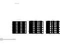
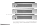
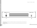
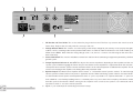
JONAS HELLBORG SIGNATURES M A N U A L
W A R W I C K
A M P L I F I C A T I O N
P
P
04
05
RECOMMENDATION
INTRODUCTION
PREAMP
07
P 08
P 09-10
P 11
P 12
P 13
P
PREAMP
QUICK START
OPERATING INSTRUCTIONS
SIMPLIFIED SCHEMETIC
TECHNICAL SPECIFICATIONS
EQ-GRAPHS
POWER AMPLIFIERS
15
16-17
P 18-19
P 20
P 21
P 22
P 23
P
POWER AMPLIFIERS
P
OPERATING INSTRUCTIONS MONO POWER
250W/500W
2/250W
OPERATING INSTRUCTIONS STEREO POWER
RACK MOUNTING
PROTECTIVE CIRCUITS
TECHNICAL SPECIFICATIONS
SIMPLIFIED SCHEMATICS
CABINETS
25-26
27
CABINETS
TECHNICAL SPECIFICATIONS
C O M B I N AT I O N P O S S I B I L I T I E S
P
P
28-29
30
COMBINATION POSSIBILITIES
WIRING EXAMPLES
INDEX
P
P
RECOMMENDATION
RECOMMENDATION
The following recommendations are to ensure that the device always functions reliably:
Never open the casing! To do so would expose you to the risk of an electric shock. Should repairs prove necessary, leave
them to qualified service personnel. Avoid dust and high moisture levels, direct sunlight and extremely high or low
temperature. Safeguard the device from excessive vibration. Always place the unit on a stable and horizontal surface.
See to adequate ventilation. The device should not be placed on soft surfaces (carpet, cushions, etc.). When mounting it
in a rack, make sure that the cooling vents remain unobstructed. Avoid leaving the unit near radiators or other objects
producing heat. Internal components should only be adjusted or cleaned by qualified service technicians. Ensure no object
or liquid penetrates the device through its cooling vents. When replacing a fuse make sure you fit in one of identical value!
Have the device examined by a qualified service technician in the following cases: the mains lead or mains switch have been
damaged, objects or liquids have penetrated the device, it has been exposed to excessive moisture, malfunctions or abnormal
operating conditions have occurred, the device has been dropped or the casing damaged.
This apparatus shall not be exposed to dripping or splashing. No objects filled with liquids, such as vases, shall be placed
on the apparatus. This apparatus should be connected to a MAINS socket outlet with a protective earth connection. If
the apparatus shows any malfunction, immediately disconnect the main power cord from the mains socket. Remove the
plug whenever changing a fuse. Only ever replace a fuse with another of the same type. Never bridge defective fuses. Make
sure the top and bottom of the device are properly ventilated and that the vents are not blocked. Do not subject the device
to excessive vibration or hard jolts as these could damage the device. Don't undertake repairs yourself. Only allow the case
to be opened by qualified personnel. (Remove the plug). Repairs should only be undertaken by qualified personnel.
Please read through these instructions before connecting and operating the device. If you keep to the guidelines set out
in this manual, you will soon be able to appreciate the excellent quality of the new Jonas Hellborg Series. Please keep
this instruction booklet handy in case you need to consult it again.
01
4
INTRODUCTION
Welcome to the Warwick family and congratulations to the purchase of one of our fine Amps.
The Jonas Hellborg Series of Bass amplification products is designed to be the highest quality system of amps specifically
for bass available today. There is truly no musical challenge that will present a problem for this extraordinary range of
products. As we all know every manufacturer claims to be producing the greatest and most uncompromising products, and
we are sure everyone has the best intent and believes in what they do. However the level of circuitry and design solutions
applied here are in the league of top of the line recording studio products rather than normal amplifiers so for the moment,
until the competition catches up we are in a league of our own. We sincerely hope you will get many years of happy use out
of your Amp(s) and Speaker(s).
Throughout the conception evolution and manufacture of the “Hellborg Amp System” quality of sound, craftsmanship and
aesthetics have been solid priorities. Of course sound is the number one issue in any musical instrument, and yes the
amplifier is without a doubt an integral part of the instrument. The main problem of “old style” bass amps is in the lack of
what one expects a bass being capable of producing. Both in regards to dynamics and frequency range. So internal headroom,
range of equalizers, dynamic power reserves of Power Amps and range and quality of Speaker Cabinets have all been sadly
short of the mark. Whatever your musical genre these amps can handle anything you put into them and the sound coming
out of the speakers will make you a happier bassist. We believe that the amp has to look as incredible as it sounds. So much
work has gone in to designing a rig that will make you proud just by looking at it, every time you look at it.
5
INTRODUCTION
GENERAL POINTS
01
02
PREAMP
PREAMP
The centre piece of the “Hellborg Amp System” is the Preamp.
The input is a combined ¼”/XLR jack providing both low (XLR) and high (¼”) impedance. The input jack is followed by an
input transformer. This imparts galvanic signal isolation and the sweetness for which good transformers are known. The
EQ section provides shelving EQ for high and low band and an inductive (coil based) EQ for the mids with stepped (fixed)
frequency and continuously variable gain. Choices of frequencies are as follows: 110, 300 and 800Hz for low mids, 1.5, 3
and 5kHz for high mids. All transformers and coils are optimally shielded in MU-metal housing. The DI output amp is driving a carefully configured output transformer for the warmest recording or PA sound.
Warning: High Voltage inside. To prevent electric shock do not open cover. Refer servicing to qualified service personnel.
To avoid fire hazard, replace fuse with same type and rating. To avoid electric shock hazard, do not operate this equipment
in rain or wet environment.
7
PREAMP
Safety Appliances
02
GETTING STARTED
QUICK START PREAMP
1.
2.
3.
4.
5.
6.
7.
8.
9.
10.
11.
12.
02
Make sure that the Power Amplifier load is matched to the connected loudspeakers load.
We recommend using speaker cables with lockable coaxial connectors that meet a cross-section of at least 2 x 1.5 mm.
Check that the mains supply has been plugged in and that the connection Pre- to Power- Amplifier is correct.
Make sure that external (effects) units possibly used are correctly connected and operational.
Set the MASTER controls (Pre- and Power Amplifier) to zero.
Plug your bass guitar into the Preamp's INPUT with a shielded line-cable.
Press the POWER switch to turn on the units.
Switch MUTE off and the red LED will extinguish.
Turn all volume controls of your bass guitar on to their maximum.
Adjust the GAIN control until the CLIP LED flashes green (Note PAD -20dB switch). The clip LED turning red indicates clipping
Set the LEVEL on the Power Amplifier to 5 and slowly increase the MASTER volume to a pleasing level.
Dial in the sound you want using the controls, described in their respective chapters.
If necessary readjust GAIN setting. Green indicates correct operating level, red indicates distorted signal.
8
PREAMP
4
1
2
3
5
6
7
8
9
10
11
12
Input Jack This Neutrik© Combo Connector provides an unbalanced ¼” and balanced XLR input. The ¼” jack is used
for all normal basses. The balanced XLR input is for instruments with balanced outputs.
2. PAD Switch Some instruments have an unusual low output level. If you own such an instrument, it may be necessary to
disengage the -20dB PAD to match the correct signal level with this Preamp. Note that the PAD should normally be engaged.
3 Gain (-6dBu to +60dBu) This control regulates and controls the gain in the whole system. The actual settings for
this control will depend on the output level of the instrument being used.
4 Clip LED Green indicates the correct operational level and red indicates clipping.
5 EQ (On/Off) Switch This switch bypasses the EQ-Section. The Control LED above the switch indicates the status.
6 Bass This adjusts the amount of Bass rates by 40Hz ±18dB. The Bass-Filter is shelving type that provides 6dB per
octave rising or falling curve shapes.
7 Lo-Mid Level This adjusts the amount of Lo-Mid rates depending on the selected frequency. The selectable frequencies
are 110, 300 and 800Hz ±15dB.
8 Hi-Mid Level This adjusts the amount of Lo-Mid rates depending on the selected frequency. The selectable frequencies
are 1.5, 3 and 5kHz ±15dB.
9 Treble This adjusts the amount of Treble rates by 15kHz ±18dB. The Treble-Filter is shelving type that provides 6dB per
octave rising or falling curve shapes.
10 Master Control This sets the signal level of the “TO POWER AMP” outputs. It should be set at -40dB when switching
on the Preamp and turned up to the desired playing volume.
11 Mute Switch Pressing this switch will mute Line out and DI out. Its status is shown on the red LED above the switch.
The mute function is useful when changing instruments or if a tuner is connected to the TUNER out, for tuning up silently.
12 Power Switch This switch is to turn on the unit. The switch will be illuminated when the Preamp power is on.
9
OPERATING INSTRUCTIONS PREAMP
1.
02
OPERATING INSTRUCTIONS PREAMP
1
1.
2.
3.
4.
5.
6.
02
2
3
4
5
6
IEC Socket and Fuse Holder This is the socket for plug in the line cord. The fuse tray contains the main fuse of the
Preamp. Replace the fuse only with the same type and size.
Voltage Selector Switch This switch is set at the factory to the correct voltage for your country. It can easily be changed
to 230V or 115V by switching to the correct position. Fuse values are T500mAL for 230V and T1AL for 115V. Note
when the wrong voltage value is set, there is a serious risk of damage to the unit if this is done incorrectly.
Tuner This is an output for connecting a Tuner. The signal from this output is identical to the instruments signal.
Effect Loop This part is for connecting effect units to the Preamp. The Send jack will be connected to the effect
unit input and the Return to the effect unit output. The Balance Control adjusts between serial and parallel mode. If
the control is turned to wet the signal will be fully processed. Turned to dry direction adjusts the mix of the effect loop.
The sensitivity is switchable between +4dB and -10dB.
To Power Amp These are two Line Out jacks for connecting the Power Amplifiers.
DI Out The DI Output is for connecting the Preamp to P.A. systems or recording consoles. The level control sets
the amount of the signal that appears at the output of the XLR connector. The DI Selector allows different settings for
the DI output signal. In the PRE EQ/EFF position is the sound uncoloured. The signal is immediately taken after the input
and gain section. By POST EQ/PRE EFF the signal is taken after the equalizer section but before EFFECT SEND. The
sound will be affected by the equalizer section. By POST EQ/EFF is the signal taken after the equalizer section and
effect loop. The sound will be affected by the equalizer and connected effect units. Wiring of the XLR connector is:
pin 1 = ground(GND), pin 2 = +(hot), pin 3 = -(cold).
10
11
SIMPLIFIED SCHEMATIC PREAMP
PREAMP
02
Input sensitivity
Level range
PAD
Input Impedance
HI-Z
LO-Z
Filter Section
Bass
TECHNICAL SPECIFICATIONS PREAMP
Lo-Mid
Hi-Mid
Treble
Effect Send
Impedance
Output Level
Effect Return
Impedance
Nominal Input Level
02
Tuner Out Level
Nominal Output
4dBu
500kΩ
600Ω
Line Out Level
Impedance
Nominal Output Level
600Ω
0dBu
Type: 6dB/oct. Shelving
Gain: ±18dB at 40Hz
DI Output
Impedance
Output Level
600Ω
Frequency Response
20Hz – 20kHz, -0.5dB
Type: 6dB/oct. Bandpass Filter,
Selectable Frequencies 1,5kHz, 3kHz and 5kHz
Gain: ±15dB
SNR
> 85dB below full conduction
THD+N at 1kHz
< 0,07%
Type: 6dB/oct. Shelving
Gain: ±18dB at 15kHz
Auxiliary
Mains Protection
Dimensions (W/H/D)
Weight
T500mAL (230V), T1AL (115V)
19" / 1HE / 9,2" (233mm)
10 lb (4,5kg)
-6dBu to +60dBu
-20dB
Type: 6dB/oct. Bandpass Filter,
Selectable Frequencies 110Hz, 300Hz and 800Hz
Gain: ±15dB
600Ω
Selectable +4dB/-10dB
Content
10kΩ
Selectable +4dB/-10dB
-15dBu to +6dBu
IEC supply cable, owners
manual, hexagon socket
12
PREAMP
Bass/Treble
Lo-Mids
Hi-Mids
20
10
dB
dB
0
-10
-20
100
1K
F/Hz
13
10K
F/Hz
F/Hz
EQ-GRAPHS PREAMP
dB
02
03
POWER AMPLIFIER
2/250W
MONO POWER AMP
250W
MONO POWER AMP
500W
The Hellborg Power Amps again are a mix of old and new ideas. They are characterized by their capacities to deliver
fast transient attacks due to over dimensioned output stage and by the warm tube like sound resulting from the large
speaker output transformers. In addition it has a range of computer controlled safety features to keep both amps and
speakers healthy and happy.
15
POWER AMPLIFIER
STEREO POWER AMP
03
OPERATING INSTRUCTIONS MONO POWER AMP
250W/500W
MONO POWER AMPS
1
1.
2.
03
2
Level Control This adjusts the main volume of the amplifier. The CLIP LED above indicates when the input stage
is being over-driven.
Power (On/Off) Switch This switch is to turn on the unit. The switch will be illuminated when the Power Amp
is turned on.
16
2
5
6
4
1
1. IEC Socket and Fuse Holder This is the socket for plug in the line cord. The fuse tray contains the main fuse of the
Power Amp. Replace the fuse only with the same type and size.
2. Voltage Selector Switch This switch is set at the factory to the correct voltage for your country. It can easily be changed to
230V or 115V by switching to the correct position FUSE values are T4AL for 230V and T8AL for 115V (T5AL/T10AL by the
Mono Power 500W). Note when the wrong voltage value is set, there is a serious risk of damage to the unit if this is
done incorrectly.
3.
4.
5.
6.
17
Ground/Lift Switch This switch is included to remove hum and buzz when connecting to equipment powered by a different
ground system.
Output Impedance Selector (2, 4 or 8Ω) This adjusts the correct impedance depending on the impedance of the used
speaker system. Before engaging the Power Amp be sure that the correct impedance is adjusted to obtain the maximum
rated power. Never connect speaker cabinets with lower load as in the selected position is labelled on the amplifier. This will
result in over heating of the amplifier and shutting down into protection mode.
Speaker Output The Mono Power Amplifier Series feature ¼” and lockable coaxial speaker sockets. To avoid damages
connect speaker cabinets before main power is applied to the unit. When connecting speaker cabinets we recommend to
use the lockable coaxial speaker socked preference to the ¼” jack as it provides a far superior connection. ¼” jacks have
been added for a user-friendly handling when it is absolutely necessary to use them (for example by old cabinets without
lockable speaker connection). Before turning on the amplifier make sure that the speakers are connected and the
impedance switch is set to the correct position.
Input ¼” jack audio input for connecting instrument Preamp.
OPERATING INSTRUCTIONS MONO POWER AMP
250W/500W
3
03
OPERATING INSTRUCTIONS STEREO POWER AMP
2/250W
STEREO POWER AMP
2
1
3
1. Level Control I & II This adjusts the main volume of each amplifier unit. The CLIP LED’s above indicates when the
inputstage is being over-driven.
2. Mode Indication LED’s These LED’s above the POWER switch indicates the consisting mode (Bridge/Stereo).
3. Power (On/Off) Switch This switch is to set on the unit. The switch will be illuminated when the power amplifier is engaged.
03
18
3
1
4
7
6
1.
2.
3.
4.
5.
6.
7.
19
5
IEC Socket and Fuse Holder This is the socket for plug in the line cord. The fuse tray contains the main fuse of the
Power Amp. Replace the fuse only with the same type and size.
Voltage Selector Switch (115V/230V) This switch is set at the factory to the correct voltage for your country. It can
easily be changed to 230V or 115V by switching to the correct position. Fuse values are T5AL for 230V and T10AL for
115V. Note when the wrong voltage value is set, there is a serious risk of damage to the unit if this is done incorrectly.
Ground/Lift Switch This switch is included to remove hum and buzz when connecting to equipment powered by a
different ground system.
Stereo/Bridged Switch This switch is to select Stereo or Bridged Mode (in bridge mode the amplifier works as a 500Wmono amp).
Output Impedance Selector (2, 4 or 8Ω Stereo/4, 8 or 16Ω Bridged) This adjusts the correct impedance depeding
on the impedance of the used speaker system. Before engaging the Power Amplifier be sure that the correct impedance
is adjusted to obtain the maximum rated power. Note the table for Stereo and Bridge setting. Never connect Speaker
Cabinets with lower load as in the selected position is labelled on the amplifier. This will result in over heating of the
amplifier and shutting down into protection mode.
Speaker Output The Stereo Power Amp features three ¼” and lockable coaxial speaker sockets for channel I,
channel II and bridged mode (center socket). To avoid damages connect Speaker Cabinets before main power
is applied to the unit. When connecting Speaker Cabinets we recommend to use the lockable coaxial speaker socked
preference to the ¼” jack as it provides a far superior connection.
¼” jacks have been added for a user-friendly handling when it is absolutely necessary to use them (for example by old
cabinets without lockable speaker connection). Before turning on the amplifier make sure that the speakers are
connected and the impedance switch is set to the correct position.
Input The Stereo Power Amps features two ¼” audio input jacks for connecting the instrument Preamp.
Input I is coupled with Input II when input II is not connected.
OPERATING INSTRUCTIONS STEREO POWER AMP
2/250W
2
03
MOUNTING OF THE POWER AMPLIFIERS
FRONT MOUNTING
REAR MOUNTING
The Hellborg Amplifiers are designed for installation in a conventional 19” rack case. 2 brackets for securing the Power
Amplifier and 4 case nuts and screws are supplied.
03
20
The new Warwick Jonas Hellborg Power Amplifiers are equipped with a series of circuits to prevent it from destruction in case of inadequate operating conditions:
Power-up delay: When the unit is switched on, the SPEAKER OUT sockets are activated with a slight delay to
protect the loudspeakers.
Short-Circuit:
In the event of a short-circuit at the Power Amp outputs, this feature prevents the output stage
transistors from destruction by quickly reducing current.
HF oscillation: By switching the Power Amp off, this safety feature prevents from damages that could be caused by
frequencies in excess of 20kHz (feedback, etc.).
Excessive
temperatures: Should the temperature-regulated fan cooler prove to be insufficient in extreme conditions, this circuit
protects the output stage transistors from destruction by switching the device off.
Note:
21
The amplifier switches automatically back to playing mode as soon as it detects the fault has
disappeared (e.g. the amplifier has overheated and cooled down again).
POWER AMPLIFIER PROTECTIVE CIRCUITS
PROTECTIVE CIRCUITS
03
TECHNICAL SPECIFICATIONS POWER AMPLIFIERS
POWER AMPLIFIERS
Specifications
Mono Power 250
Mono Power 500
Stereo Power 2/250
Input Sensitivity
0dBu
0dBu
0dBu
Input Impedance
5kΩ
5kΩ
5kΩ
Frequency Response
25Hz to 16kHz, -3dB
25Hz to 16kHz, -3dB
25Hz to 16kHz, -3dB
SNR
> 70dB
> 70dB
> 70dB
THD+N at 1kHz
< 0,1% below rated power
< 0,1% below rated power
< 0,1% below rated power
Output Power Rating
250W at 2/4/8Ω
500W at 2/4/8Ω
2x250W at 2/4/8Ω
1x500W at 4/8/16Ω (Bridged)
Mains Protection
T4AL (230V); T8AL (115V)
T5AL (230V); T10AL (115V)
T5AL (230V);T10AL (115V)
Dimensions (W/H/D)
19" / 1HE / 9,2" (233mm)
19" / 2HE / 15,6" (370mm)
19" / 2HE / 16,5" (420mm)
Weight
32lb(14,5kg)
42lb(19kg)
46,35lb(21kg)
Content
IEC supply cable, owners manual, 2x
hexagon sockets, rear mounting brackets
IEC supply cable, owners manual, 2x
hexagon sockets, rear mounting brackets
IEC supply cable, owners manual,
2x hexagon sockets, rear mounting brackets
Auxiliary
03
22
STEREO POWER
MONO POWER
250/500W
23
SIMPLIFIED SCHEMATIC POWER AMPLIFIERS
2/250W
03
04
CABINETS
The philosophy behind the cabinets is to through correct cabinet design and use of specifically designed speaker drivers
create clear full and loud sounding bass cabinets that projects over large spaces.
25
CABINETS
CABINETS
04
CABINETS
CABINETS
Club Cab
Big Cab
Hi Cab
Lo Cab
The Club Cab is designed to be portable, full range and loud enough to
deal with any small venue or club setting. It basically is the top half of the
Big Cab, with the same specially
designed Celestion coaxial 15-inch
speaker inside. It outperforms any
4x10 cabinet in the realms attack
and clarity and still has a big,
warm bottom end.
The Big Cab is a full range, high-performance
speaker cabinet. It comes loaded with two
Celestion 15-inch speakers. One coaxial 15inch speaker was developed in cooperation
with Celestion and is a powerful full range
speaker that takes advantage of the phase
linearity that coaxial technology (high frequency driver in the middle of the bass driver)
gives. This is a hybrid bandpass cabinet an
old trusted design that gives excellent low
frequency response with the frontloaded coaxial a real Hi-Fi construction that will forever
clear the bass fog and let you be heard.
The Hi Cab was created to compete
with loud guitars. It will give the clarity, presence and the full sound that
you need competing with a noisy
musical environment. The Hi Cab
can be combined with the Big Cab
or the Lo Cab to make an impressive bass stack. It is loaded with two
Celestion 12-inch full range speakers.
The Lo Cab is a low-end compliment
to the Hi Cab and the Club Cab. The
single Celestion 15-inch speaker is
warm and punchy, adding a strong
foundation to your bass tone.
04
26
Specifications
Big Cab
Club Cab
Hi Cab
Lo Cab
Type
2x15 direct radiating
bandpass cabinet
1x15 bass reflex cabinet
2x12 bass reflex cabinet
1x15 bass reflex cabinet
Frequency Response
40Hz - 20kHz
50Hz - 20kHz
50Hz - 8kHz
40Hz - 3kHz
Power Rating
500W RMS
250W RMS
200W RMS
300W RMS
Impedance
4Ω
8Ω
4Ω
8Ω
Sensitivity
102dB SPL at 1w/1m
99dB SPL at 1w/1m
100dB SPL at 1w/1m
99dB SPL at 1w/1m
Speaker
1 x custom designed Celestion
15" coaxial speaker and
1 x 15" Celestion bass speaker
1 x custom designed Celestion
15" coaxial speaker
2 x Celestion
12" full range speakers
1 x 15" Celestion bass speaker
Dimensions (HxWxD)
42“x 21“x18“
106,5 x 53,5 x 45,5cm
24“x 21“x 16“
61 x 53,5 x 41,5cm
26.5“x 21“x 15“
67 x 53,5 x 38cm
24“x 21“x 16“
61 x 53,5 x 41,5cm
Weight
92.6lb (42kg)
48.5lb (22kg)
53lb (24kg)
48.5lb (22kg)
27
TECHNICAL SPECIFICATIONS CABINETS
TECHNICAL
SPECIFICATIONS
04
Cabinet
Combinations
Club Cab
&
Lo Cab
Hi Cab
&
Big Cab
Hi Cab
&
Lo Cab
Big Cab
Pre & 250W
x
Pre & 500W
x
x
Pre & Stereo 2/250W
x
x
Pre & 250W & 250W
x
Club Cab
COMBINATIONS
x
x
x
Pre & 250W & Stereo 2/250W
x
Pre & 250W & 500W
x
Club and Lo Cab
The Club and Lo Cab can be satisfactory powered by the 250W Mono, the 500W Mono, the 2x250W Stereo or two separate 250W Mono Amps. The first combination with the 250W Mono Amp is powerful enough for most applications if one
however needs some extra kick the other combinations are recommended. The Stereo Amp offers the possibility to adjust
the volume of each cabinet separately.
COMBINATION POSSIBILITIES
Big Cab
The Big Cab requires a powerful amplifier so either the 500W Mono or the 2x250W Stereo in bridged mode can be used.
Club Cab
The Club Cab can be powered by either the 250W or 500W Mono Amps. The 250W Mono Amp will power the Club Cab adequately for smaller gigs. With the 500W Mono Amp gives you the possibility to expand your system to a powerful setup for
bigger venues.
Hi and Big Cab
The Hi and Big Cab are ideally powered by the combination of a 250W Mono and a 500W Mono Amp.(the 500W could be
replaced by a stereo unit in bridge mode). This setup is the loudest and most open sounding. It will not be drowned out in any
sort of sonic mayhem.
Hi and Lo Cab
The Hi and Lo Cab requires two 250W Mono Amps. Because of the difference in impedance between the 2 cabinets you need
separate amps so you can adjust the impedance correctly.
05
28
Hi & Big Cab
Hi & Lo Cab
Big Cab
Club Cab
COMBINATION POSSIBILITIES
Club & Lo Cab
05
WIRING
Preamp & 500W & 250W
Preamp & 250W & 250W
Preamp & Stereo 2/250W
Preamp & Stereo 2/250W
WIRING EXAMPLES
Preamp & 250W
05
Club & Lo Cab
Hi & Big Cab
Hi & Lo Cab
Big Cab
Club Cab
30
Headquarters:
Branch China:
Branch UK:
Branch Switzerland:
Branch CZ/SK:
Branch PL:
Warwick GmbH&Co.Music Equipment KG • Gewerbepark 46 • 08258 Markneukirchen/Germany • E-Mail: [email protected]
Warwick Music Equipment (Shanghai) Ltd., Co.• Shanghai Waigaoqiao Free Trade Zone • Shanghai 200131/P.R.China • E-Mail: [email protected]
Warwick Music Equipment Trading (Manchester UK) Ltd. • 75 Bridge Street • Manchester M3 2RH / Great Britain • E-Mail: [email protected]
Warwick Music Equipment Trading (Zurich) GmbH • Kriesbachstrasse 30 • 8600 Dübendorf / Switzerland • E-Mail: [email protected]
Warwick Music Equipment Trading (Praha CZ) s.r.o. • Spálená 23/93 • 11000 Praha 1 / Czech Republic • E-Mail: [email protected] z
Warwick Music Equipment Trading (Warsaw) Sp. z o.o. • Flory 7/18a • 00-586 Warsaw / Poland • E-Mail: [email protected]
Visit us on the World Wide Web: http://www.warwick.de & join us in WARWICK BASS FORUM: www.warwick.de/forum