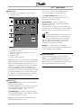
1
VLT® 2800 Series
■ Quick
Setup
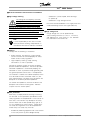
■ General warning
Using this Quick Setup, you can carry out quick and
EMC-correct installation of the frequency converter
in five steps. The Operating Instructions, which are
also enclosed, give other examples of installation
and describe all functions in detail.
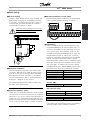
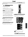
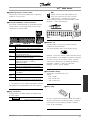
■ Electrical Installation, control cables
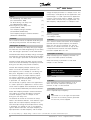
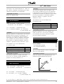
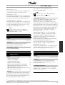
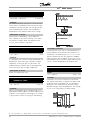
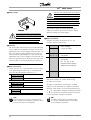
Remove the front cover underneath the control panel.
Place a jumper between terminals 12 and 27.
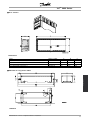
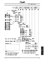
■ Mechanical Installation
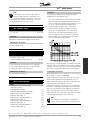
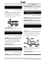
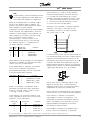
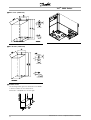
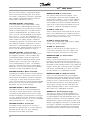
VLT 2800 frequency converters allow side-by-side
installation. Because of the need for cooling, there
must be 10 cm free air passage above and below
the frequency converter. Drill holes in accordance
with the measurements given in section Mechanical
dimensions. Retighten all four screws.
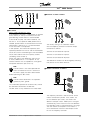
Fit the decoupling plate to the power cables and
the earth screw (terminal 95).
Quick
Setup
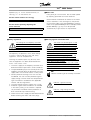
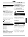
Read the safety instructions on the next
page before installing the unit.
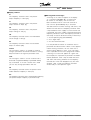
■ Programming
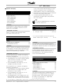
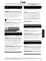
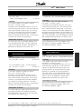
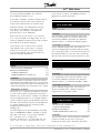
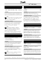
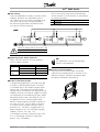
Carry out programming on the control panel. Press
the [QUICK MENU] key to enter the Quick menu. In
this menu, parameters can be selected by means of
the [+] and [-] keys. The parameter values can be
changed by pressing [CHANGE DATA]. Changes are
programmed using the [+] and [-] keys. Finish the
change of a parameter setting by pressing [CHANGE
DATA]. A change of parameter values is saved
automatically after a mains failure. If the display shows
three dots at the right, the parameter value has more
than three digits. In order to see the value, activate
[CHANGE DATA]. Press [QUICK MENU]: Set the motor
parameters that are on the nameplate of the motor:
Motor
Motor
Motor
Motor
Rated
power [kW]
voltage [V]
frequency [Hz]
current [A]
motor speed
parameter
parameter
parameter
parameter
parameter
102
103
104
105
106
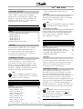
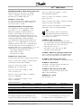
Activate AMT:
Automatic motor tuning
parameter 107
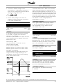
Set reference range
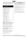
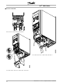
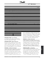
■ Electrical Installation, power
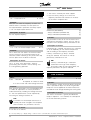
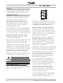
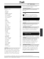
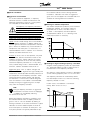
Please note that the power terminals can be removed.
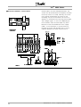
Connect mains to the mains terminals of the frequency
converter, i.e. 91, 92, 93 and the earth connection to
terminal 95. Fit a screened/armoured cable from the
motor to the motor terminals of the frequency converter,
i.e. U, V, W. The screen ends in a screen connector.
MG.28.A9.02 - VLT is a registered Danfoss trademark
Min. reference, RefMIN
Max. reference, Ref MAX
Ramp-up time [s]
Ramp-down time [s]
parameter 204
parameter 205
parameter 207
parameter 208
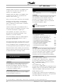
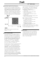
In parameter 002 Local/remote control, the frequency
converter mode can be selected as Remote
3