1
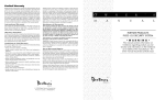
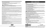
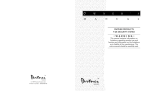
INSTRUCTION
MANUAL
29000525 R0
November 22 1993
PC115O
FCC COMPLIANCE
CAUTION: Changes or modifications not expressly approved by Digital Security Controls Ltd. could void your authority to use this equipment.
This equipment has been tested and found to comply with the limits for a Class B digital device, pursuant to Part 15 of the FCC Rules. These
limits are designed to provide reasonable protection against harmful interference in a residential installation. This equipment generates, uses
and can radiate radio frequency energy and, if not installed and used in accordance with the instructions, may cause harmful interference to
radio communications. However, there is no guarantee that interference will not occur in a particular installation. If this equipment does cause
harmful interference to radio or television reception, which can be determined by turning the equipment off and on, the user is encouraged to
try to correct the interference by one or more of the following measures:
• Re-orient the receiving antenna.
• Increase the separation between the equipment and receiver.
• Connect the equipment into an outlet on a circuit different from that to which the receiver is connected.
• Consult the dealer or an experienced radio/television technician for help.
The user may find the following booklet prepared by the FCC useful: “How to Identify and Resolve Radio/Television Interference Problems”. This
booklet is available from the U.S. Government Printing Office, Washington D.C. 20402, Stock # 004-000-00345-4
IMPORTANT INFORMATION
This equipment complies with Part 68 of the FCC Rules. On the side of this equipment is a label that contains, among other information, the FCC
registration number of this equipment.
Notification to Telephone Company
Upon request, the customer shall notify the telephone company of the particular line to which the connection will be made, and provide the FCC
registration number and the ringer equivalence of the protective circuit.
PC1150 FCC Registration Number: F53CAN-73151-AL-E
Ringer Equivalence Number: 0.1B
USOC Jack: RJ-31X
Telephone Connection Requirements
Except for the telephone company provided ringers, all connections to the telephone network shall be made through standard plugs and
telephone company provided jacks, or equivalent, in such a manner as to allow for easy, immediate disconnection of the terminal equipment.
Standard jacks shall be so arranged that, if the plug connected thereto is withdrawn, no interference to the operation of the equipment at the
customer’s premises which remains connected to the telephone network shall occur by reason of such withdrawal. Ensure that plugs and jacks
meet the dimension, tolerance and metallic plating requirements of 47 C.F.R. Part 68 Subpart F.
Incidence of Harm
Should terminal equipment or protective circuitry cause harm to the telephone network, the telephone company shall, where practicable, notify
the customer that temporary disconnection of service may be required; however, where prior notice is not practicable, the telephone company
may temporarily discontinue service if such action is deemed reasonable in the circumstances. In the case of such temporary discontinuance,
the telephone company shall promptly notify the customer and will be given the opportunity to correct the situation.
Additional Telephone Company Information
The security control panel must be properly connected to the telephone line with a USOC RJ-31X telephone jack.
The FCC prohibits customer-provided terminal equipment be connected to party lines or to be used in conjunction with coin telephone service.
Inter-connect rules may vary from state to state.
Changes in Telephone Company Equipment of Facilities
The telephone company may make changes in its communications facilities, equipment, operations or procedures, where such actions are
reasonably required and proper in its business. Should any such changes render the customer’s terminal equipment incompatible with the
telephone company facilities the customer shall be given adequate notice to the effect modifications to maintain uninterrupted service.
Ringer Equivalence Number (REN)
The REN is useful to determine the quantity of devices that you may connect to your telephone line and still have all of those devices ring when
your telephone number is called. In most, but not all areas, the sum of the RENs of all devices connected to one line should not exceed five (5.0).
To be certain of the number of devices that you may connect to your line, you may want to contact your local telephone company.
Equipment Maintenance Facility
If you experience trouble with this telephone equipment, please contact the facility indicated below for information on obtaining service or repairs.
Do not return equipment to this address without prior authorization. The telephone company may ask that you disconnect this equipment from
the network until the problem has been corrected or until you are sure that the equipment is not malfunctioning.
Digital Security Controls Ltd.
160 Washburn Street
Lockport, NY 14094
Limited Warranty
Digital Security Controls Ltd. warrants that for a period of twelve months from the date of purchase, the
product shall be free of defects in material and workmanship under normal use and that in fulfilment of
any breach of such warranty, Digital Security Controls Ltd. shall, at its option, repair or replace the
defective equipment upon return of the equipment to its repair depot. This warranty applies only to
defects in parts and workmanship and not to damage incurred in shipping or handling, or damage due to
causes beyond control of Digital Security Controls Ltd. such as lightning, excessive voltage, mechanical
shock, water damage, or damage arising out of abuse, alteration or improper application of the
equipment.
The foregoing warranty shall apply only to the original buyer, and is and shall be in lieu of any and all
other warranties, whether express or implied and of all other obligations or liabilities on the part of Digital
Security Controls Ltd. This warranty contains the entire warranty. Digital Security Controls Ltd. neither
assumes, nor authorizes any other person purporting to act on its behalf to modify or to change this
warranty, nor to assume for it any other warranty or liability concerning this product.
In no event shall Digital Security Controls Ltd. be liable for any direct , indirect or consequential damages,
loss of anticipated profits, loss of time or any other losses incurred by the buyer in connection with the
purchase, installation or operation or failure of this product.
WARNING
Digital Security Controls Ltd. recommends that the entire system be completely tested on
a regular basis. However, despite frequent testing, and due to but not limited to, criminal
tampering or electrical disruption, it is possible for this product to fail to perform as
expected.
Keypad Zones
System Information
There are three zones that can be activated from the keypad by pressing and holding two keys at the
same time. These keys are only functional if they have been programmed by your installer. The installer
should indicate which of these keys are functional, and the functional keys should be noted on the
System Information page in this manual.
Zone
Protected Area
Zone Type
1
_________________________________________________
________________________
[1]+[3]: Holding these keys down for two seconds will sound a Pulsed Alarm. The siren will sound in a
2
_________________________________________________
________________________
pulsing mode. The keypad will sound three beeps once the system has accepted the alarm. An auxiliary
warning device is also activated if your installer has connected it to your system. To silence the alarm, enter
an Access Code.
3
_________________________________________________
________________________
4
_________________________________________________
________________________
[4]+[6]: Holding this key down for two seconds activates a silent alarm if your installer has
programmed this option. When activated, there is no audible alarm and no lights on the keypad will
come on. When the system has accepted the alarm, the keypad will sound a series of beeps. An
auxiliary warning device is activated only if connected to your system by your installer.
[∗]+[#]: Holding this key down for two seconds will produce a steady tone on your siren if your installer
has programmed this key for audible operation. An auxiliary warning device is also activated if your
installer has connected it to your system. Enter an Access Code to silence the alarm.
Pulsed Alarm
[1]+[3]
Enabled
Auxiliary Alarm
[4]+[6]
Enabled
Panic Alarm
[ ]+[#]
Access Code
Assigned To
Testing Your System
∗
Enabled
2
___________________________________________________
3
___________________________________________________
1 Inform the monitoring station that you are testing your system.
4
___________________________________________________
2 Disarm the system (“Ready” light ON).
5
___________________________________________________
6
___________________________________________________
It is recommended that you test your system weekly.
NOTE: Perform system tests in the off-peak hours, such as early morning or late evening.
∗
3 Perform a siren/battery test by pressing [ ][6][Master Code]+[8]. The signal will sound for about 2
seconds. If a trouble occurs after the test, press [ ][2] to view the trouble condition.
∗
4 Activate each sensor in turn (for example, open a door or window, or walk in motion detector areas).
Observe the Zone Lights come ON as each zone is activated. The Zone Lights will go OFF when the
system restores to normal (i.e. door or window closed).
Master Code:
________________________________
Entry Delay:
_______________ seconds
5 If they are programmed for operation, activate the [1]+[3], [4]+[6] and [ ]+[#] functions. [1]+[3] will
sound the siren in a pulsed mode. Enter the Access Code to silence the alarm. [4]+[6] key is silent; the
[ ]+[#] may be programmed as silent or audible. If the alarm sounds, enter the Access Code to
silence.
Exit Delay:
_______________ seconds
6 Should the system fail to operate properly, call your alarm dealer for service.
Call:
__________________________________________________________
Phone:
__________________________________________________________
∗
∗
7 When testing is complete, call and advise the monitoring station.
Maintenance
With normal use, the system requires minimum maintenance. The following points should be observed:
For Service:
Notes
1 Do not wash the keypad with a wet cloth. Light dusting with a slightly damp cloth should remove
normal accumulations of dust.
2 The sire/battery test is designed to determine battery condition. However, it is recommended that the
stand-by battery be replaced every three years.
3 For other system devices such as passive infrared, ultrasonic or microwave motion detectors,
glassbreak detectors or smoke detectors, consult the respective manufacturer’s literature for testing
and maintenance.
8
1
About Your Security System
Your DSC security equipment has been designed to give the greatest possible flexibility and
convenience. Read this manual carefully and have your installer instruct you on system operation and on
which features have been implemented in your system. All users of this system should be equally
instructed in its use. Fill out the System Information page and store this manual in a safe place for future
reference.
PC1150 Keypad
The Zone Lights will come ON when the system is disarmed
to indicate that there is activity in a zone. Refer to the System
Information page at the front of this manual for zone information.
Testing
To ensure that your system continues to function as intended, it is important that you test your system
weekly. See the testing procedure elsewhere in this manual. If your system does not function properly,
call your installing company for service.
Zone
Zone
Zone
Zone
General System Operation
Your security system is made up of a DSC PC1150 Control Panel and various sensors and detectors. The
control panel is designed to be mounted flush with a wall in a conveniently accessible location. The
metal cabinet contains the system electronics, fuses and stand-by battery. There is normally no reason
for anyone but the installer or service personnel to have access to the control panel. The PC1150 keypad
has an audible indicator (buzzer), a group of zone and system status lights and command entry keys.
The keypad is used to send commands to the system and to display the current system status. The
security station will be mounted in a convenient location inside the protected premises close to the entry/
exit door(s).
Ready
Armed
System
1
2
3
4
5
6
7
8
9
0
#
The “Armed” light will come ON to
indicate that the system is armed. To
arm the system, first ensure that the
“Ready” light is ON, then enter an
Access Code.
ACCESS
PC115O
DOC LN/MDC IC 2
The security system has several zones of area protection and each of these zones will have one or more
sensors connected to it (motion detectors, glassbreak detectors, door contacts, etc.). When a sensor is
in alarm, the affected zone will be indicated on the PC1150 (Zone Lights 1 through 4).
Important Notice
A security system cannot prevent emergencies. It is only intended to alert you and, if
included, a monitoring station, of an emergency situation. Security systems are generally
very reliable but they may not work under all conditions and they are not a substitute for
prudent security practices or life and property insurance. Your security system should be
installed and serviced by qualified security professionals who should instruct you on the
level of protection that has been provided and on system operations.
1
2
3
4
The “Ready” light will come ON to indicate
that the system is ready to be armed.
When the “Ready” light is OFF, there is an
open zone on the system. All zones must
be either secure or bypassed before the
system may be armed.
Keypad Zones:
Press [1]+[3] for 2 seconds to activate a Pulsed alarm
Press [4]+[6] for 2 seconds to activate an Auxiliary alarm
Press [ ]+[#] for 2 seconds to activate a Panic alarm
∗
The Keypad Zones will not function unless they are enabled
by your Installer.
The “System” light is used to indicate a
number of conditions on the system that
may require attention before the system is
armed. When the “System” light is ON,
check the following:
• press [ ][1][9] to view Bypassed
Zones
• press [ ][2] to view Trouble
Conditions
• press [ ][3] to view the Alarm Memory
Display
∗
∗
∗
Refer to this instruction manual for
complete instructions on using these
features.
Press [#]...
• when an error is made in entering
code, then enter code again.
Trouble Conditions: The “System” light will come ON when there is a fault on
•
to return
to ready
state
[2]after using
the system. Press any key to silence the keypad sounder.
Press
[ ] then
[
]
commands.
to display the trouble condition. Call for service if you are unable to correct a
∗
∗
trouble condition.
Light
Trouble Type
What to do
Zone 1
Low battery
Call for service
Zone 2
AC failure (keypad
buzzer will not sound)
Check fusebox for
open fuses; call for service
Zone 3
System Fuse open
Call for service
Zone 4
Fail to communicate
Call for service
“Ready”
Not used to indicate troubles
Clock needs resetting
Reset the system time
“Bypass”
2
7
If An Alarm Sounds
If an intrusion alarm sounds (continuous siren tone), the alarm may not be silenced by entering your Access
Code. If the alarm was unintentional, call local authorities immediately to avoid an unnecessary response.
You can determine the source of the alarm by following the instructions in the Alarm Viewing section of
this manual. Once the source of the alarm has been corrected, the system can be restored to its original
armed state.
Zone Bypassing
Use Zone Bypassing when access is needed to part of the protected area while the system is armed.
Bypassed zones will not cause an alarm. Zones that are temporarily out of service due to damaged
wiring or contacts may be bypassed to allow system arming (partial protection) until repairs can be made.
Zones cannot be bypassed after the system is armed.
To bypass zones:
∗
Enter [ ][1][Zone number(s) to be bypassed]
Enter zone number(s) as single digits (1-4).
As each zone is bypassed, the Zone Light will come ON. If a zone is bypassed in error, press that zone
number again and the Zone Light will go OFF indicating that the zone is not bypassed.
Press [#] to return to “Ready”.
To recall last group of zones bypassed:
∗
Enter [ ][1][9]
Zone lights for the last group of zones bypassed will come ON to show which zones are bypassed. If you
wish to add or delete a zone from the group, press [#] to exit then follow the instructions for zone
bypassing as described above.
Press [#] to return to “Ready”.
For security reasons, your installer may prevent the bypass command from working on certain zones.
The “System” light is ON as long as ONE or more zones are bypassed. Do not unintentionally arm the
system with zones bypassed. Zone bypasses are automatically cancelled each time the system is
disarmed and must be re-applied before the next arming.
Viewing Trouble Conditions
The PC1150 continuously monitors a number of possible trouble conditions. If one of these trouble
conditions occur, the keypad will beep twice every 10 seconds and the keypad “System” indicator will
light. Pressing any key on the keypad will silence the sounder but the “System” light will remain ON until
the trouble condition is cleared. If you cannot determine the cause of the trouble condition, contact your
installer for assistance.
∗
Press [ ][2] to display the type of trouble. A Zone Light will come on to indicate which type of trouble
exists. Press [#] to return to “Ready”.
Light
Trouble Condition
1 ................. Low or disconnected stand-by battery
2 ................. Loss of AC power (Loss of AC power will turn on the
.................. trouble light but keypad sounder will not sound)
3 ................. Siren fuse open
4 ................. Unsuccessful communication attempt
“Ready” ........... Not used
“Armed” ........... Loss of time on the system clock
6
Master Code
The 4-digit Master Code is used to arm and disarm the security system, to program additional Access
Codes and to change other system features. The Master Code will be supplied to you by your installer. All
keypad entries are made by pressing one key at a time.
Arming the System
Check the following items before arming the system:
Bypassed Zones
If the “System” light is ON, ensure that zones are intentionally bypassed before arming the system (See
Zone Bypassing section).
Trouble Indications
The “System” light is also used to warn of trouble conditions in the system. If the “System” light is ON,
check to see what the trouble condition is and call for service. (See Viewing Trouble Conditions section).
Ready Light
If the “Ready” light is NOT ON, check to see that all doors and windows are closed and that motion is
stopped in areas covered by motion detectors. The system cannot be armed unless the “Ready” light
is ON, indicating that all zones are closed.
NOTE: The system may be armed with a zone bypassed or a trouble present but your security
protection will be reduced.
To Arm The System
Enter your 4-digit Access Code. As each digit is entered, the keypad sounder will beep. If the correct
Access Code is entered, the keypad sounder will beep quickly and the “Armed” light will come ON.
If the Access Code was entered incorrectly or the “Ready” light comes ON, the keypad buzzer will sound
steadily for 2 seconds. If this occurs, press the [#] key and re-enter your Access Code.
When the correct Access Code is entered and the “Armed” light comes ON, exit the premises through
the door indicated by your installer as the Exit-Entry door. At the end of the exit delay period, all lights,
except the “Armed” light, will go out and the system will be armed. The exit time delay can be changed
by your installer.
Auto-Bypass Option - Home-Away Arming
This feature, if selected by your installer, will allow you to arm your system with any Access Code and
the system will automatically bypass the interior zones. When activated, the “System” light will come on.
If you exit within the allowed exit time, the system will automatically activate the interior zones and the
“System” light will go out. This feature is designed to save the customer from having to manually bypass
interior zones each time they wish to arm the system and remain at home.
In residential applications where the system has been armed and the interior zones are automatically
bypassed, the interior zones can be reactivated from a keypad that is outside the interior zone's
protection area. To reactivate the interior zones, press [ ] then [1] and the “System” light will go out.
∗
Entry Delay Off Arming
∗
If you wish to arm your system and eliminate the entry delay, enter [ ][9] before your Access Code. The
“Armed” light will flash as a reminder that the system is armed and has no entry delay. An entry through
any zone programmed as a delay zone will create an instant alarm.
∗
To arm without entry delay, press [ ][9][Access Code]
3
Disarming the System
Programming Access Codes
Enter the premises only through the door(s) designated by your installer as the Exit-Entry door. Entering
by any other door will sound an immediate alarm. As soon as the entry door is opened, the keypad
sounder will come on to indicate that the system should be disarmed. Go to the keypad and enter your
Access Code. If an error is made entering the code, press the [#] key and enter your code again. As
soon as the correct code is entered, the “Armed” light will go out and the keypad sounder will silence.
The correct Access Code must be entered before the entry time expires. The entry time delay may be
changed by your installer.
If an alarm occurred during the period the system was armed, the “System” light and the Zone Light of
the zone that caused the alarm will flash for two minutes. After the two minute period, the “System” light
and Zone Light will stop flashing and the system will return to the ready state. Pressing the [#] key during
the two minute period will cancel the alarm memory display.
If a trouble is present when the system is disarmed, the “System” light will come ON (See Viewing Trouble
Conditions section to determine the source of the trouble). Note that troubles will not display while the
system is in the Alarm Memory Display Mode.
If you return home and find that an alarm has occurred while you were away, it is possible that an intruder
may still be on the premises. Go to a neighbour's house, and call the local police to investigate.
Quick Arm Feature
Your Installer will inform you of whether or not that Quick-Arm feature is enabled on your system. When
the Quick-Arm feature is enabled, the system may be armed simply by pressing [ ][0] instead of a 4 digit
Access Code. This feature allows a person to arm but not disarm the system.
∗
Press [#] to return to “Ready”.
Door Chime Feature
The door chime feature is used, while the system is disarmed, to provide a tone from the keypad each
time a door or window is opened or closed. The doors and windows which will provide this indication are
programmed by your installer.
∗
Enter [ ][6][Master Code][6] to turn the door chime feature ON and OFF. When the command is entered,
the keypad buzzer will beep 3 times if the door chime feature is being enabled, and will sound one long
beep if it is being disabled.
Press [#] to return to “Ready”.
Alarm Test
∗
Enter [ ][6][Master Code][8] for a 2-second test of the keypad lights, keypad buzzer, battery and the
siren.
Press [#] to return to “Ready”.
Changing The Master Code
∗
Enter [ ][5][current Master Code][new Master Code]
Press [#] to return to “Ready”.
Record your new Master Code on the System Information page in this booklet.
Changing Access Codes
Up to 5 additional Access Codes (2 through 6) may be programmed. The 6th Access Code may be
established by your installer as a One-Time Use code.
To program a new code:
∗
Enter [ ][5][Master Code]. Codes that are already programmed will be indicated by the Zone lights
and the “Ready” and “Armed” lights. The “Ready” light represents Access Code 5, and the “Armed”
light represents Access Code 6.
Enter the number of the Access Code to be programmed as a single digit, then enter the new 4-digit
Access Code. Press [#] to return to “Ready”.
If an Access Code already exists, it will be replaced by the new code. Record your new code(s) on the
System Information page in this book.
To remove a code:
∗
Enter [ ][5][Master Code][code number][
∗∗∗∗].
Press [#] to return to “Ready”.
Do not erase the Master Code (code number 1).
NOTE: It is recommended that the factory-set Master Code [1234] not be used.
One-Time Use Code
The One-Time Use code is designed for entry and exit of the premises for one occasion only. The system
must be programmed by the installer for this option to be enabled. The 6th Access Code is the one-time
code.
To use this code, enter your one-time code as the 6th Access Code using the previously described
commands. When you leave the premises, arm your system with any Access Code except the newly
entered one-time use code. This one-time code is given to a person, such as service personnel, who will
enter the premises while the system is armed and you are away.
The one-time code user enters the premises and disarms the system using the one-time Access Code.
Upon leaving, the same code is used to arm the system. As soon as the system is armed, the one-time
code is erased and can not be used to re-enter the premises. A different code can be provided each time
for the one-time user.
Alarm Memory Display
If the “System” light is ON when the system is disarmed, an alarm has occurred during the last armed
period. The alarm memory will automatically be displayed when the system is disarmed (See Disarming
the System).
∗
Press [ ] then [3] to display the zone which caused the alarm.
Press [#] to return to “Ready”.
NOTE: The alarm memory is cleared each time the system is armed so that any alarms showing are
alarms that occurred only during the last armed period.
4
5
If An Alarm Sounds
If an intrusion alarm sounds (continuous siren tone), the alarm may not be silenced by entering your Access
Code. If the alarm was unintentional, call local authorities immediately to avoid an unnecessary response.
You can determine the source of the alarm by following the instructions in the Alarm Viewing section of
this manual. Once the source of the alarm has been corrected, the system can be restored to its original
armed state.
Zone Bypassing
Use Zone Bypassing when access is needed to part of the protected area while the system is armed.
Bypassed zones will not cause an alarm. Zones that are temporarily out of service due to damaged
wiring or contacts may be bypassed to allow system arming (partial protection) until repairs can be made.
Zones cannot be bypassed after the system is armed.
To bypass zones:
∗
Enter [ ][1][Zone number(s) to be bypassed]
Enter zone number(s) as single digits (1-4).
As each zone is bypassed, the Zone Light will come ON. If a zone is bypassed in error, press that zone
number again and the Zone Light will go OFF indicating that the zone is not bypassed.
Press [#] to return to “Ready”.
To recall last group of zones bypassed:
∗
Enter [ ][1][9]
Zone lights for the last group of zones bypassed will come ON to show which zones are bypassed. If you
wish to add or delete a zone from the group, press [#] to exit then follow the instructions for zone
bypassing as described above.
Press [#] to return to “Ready”.
For security reasons, your installer may prevent the bypass command from working on certain zones.
The “System” light is ON as long as ONE or more zones are bypassed. Do not unintentionally arm the
system with zones bypassed. Zone bypasses are automatically cancelled each time the system is
disarmed and must be re-applied before the next arming.
Viewing Trouble Conditions
The PC1150 continuously monitors a number of possible trouble conditions. If one of these trouble
conditions occur, the keypad will beep twice every 10 seconds and the keypad “System” indicator will
light. Pressing any key on the keypad will silence the sounder but the “System” light will remain ON until
the trouble condition is cleared. If you cannot determine the cause of the trouble condition, contact your
installer for assistance.
∗
Press [ ][2] to display the type of trouble. A Zone Light will come on to indicate which type of trouble
exists. Press [#] to return to “Ready”.
Light
Trouble Condition
1 ................. Low or disconnected stand-by battery
2 ................. Loss of AC power (Loss of AC power will turn on the
.................. trouble light but keypad sounder will not sound)
3 ................. Siren fuse open
4 ................. Unsuccessful communication attempt
“Ready” ........... Not used
“Armed” ........... Loss of time on the system clock
6
Master Code
The 4-digit Master Code is used to arm and disarm the security system, to program additional Access
Codes and to change other system features. The Master Code will be supplied to you by your installer. All
keypad entries are made by pressing one key at a time.
Arming the System
Check the following items before arming the system:
Bypassed Zones
If the “System” light is ON, ensure that zones are intentionally bypassed before arming the system (See
Zone Bypassing section).
Trouble Indications
The “System” light is also used to warn of trouble conditions in the system. If the “System” light is ON,
check to see what the trouble condition is and call for service. (See Viewing Trouble Conditions section).
Ready Light
If the “Ready” light is NOT ON, check to see that all doors and windows are closed and that motion is
stopped in areas covered by motion detectors. The system cannot be armed unless the “Ready” light
is ON, indicating that all zones are closed.
NOTE: The system may be armed with a zone bypassed or a trouble present but your security
protection will be reduced.
To Arm The System
Enter your 4-digit Access Code. As each digit is entered, the keypad sounder will beep. If the correct
Access Code is entered, the keypad sounder will beep quickly and the “Armed” light will come ON.
If the Access Code was entered incorrectly or the “Ready” light comes ON, the keypad buzzer will sound
steadily for 2 seconds. If this occurs, press the [#] key and re-enter your Access Code.
When the correct Access Code is entered and the “Armed” light comes ON, exit the premises through
the door indicated by your installer as the Exit-Entry door. At the end of the exit delay period, all lights,
except the “Armed” light, will go out and the system will be armed. The exit time delay can be changed
by your installer.
Auto-Bypass Option - Home-Away Arming
This feature, if selected by your installer, will allow you to arm your system with any Access Code and
the system will automatically bypass the interior zones. When activated, the “System” light will come on.
If you exit within the allowed exit time, the system will automatically activate the interior zones and the
“System” light will go out. This feature is designed to save the customer from having to manually bypass
interior zones each time they wish to arm the system and remain at home.
In residential applications where the system has been armed and the interior zones are automatically
bypassed, the interior zones can be reactivated from a keypad that is outside the interior zone's
protection area. To reactivate the interior zones, press [ ] then [1] and the “System” light will go out.
∗
Entry Delay Off Arming
∗
If you wish to arm your system and eliminate the entry delay, enter [ ][9] before your Access Code. The
“Armed” light will flash as a reminder that the system is armed and has no entry delay. An entry through
any zone programmed as a delay zone will create an instant alarm.
∗
To arm without entry delay, press [ ][9][Access Code]
3
About Your Security System
Your DSC security equipment has been designed to give the greatest possible flexibility and
convenience. Read this manual carefully and have your installer instruct you on system operation and on
which features have been implemented in your system. All users of this system should be equally
instructed in its use. Fill out the System Information page and store this manual in a safe place for future
reference.
PC1150 Keypad
The Zone Lights will come ON when the system is disarmed
to indicate that there is activity in a zone. Refer to the System
Information page at the front of this manual for zone information.
Testing
To ensure that your system continues to function as intended, it is important that you test your system
weekly. See the testing procedure elsewhere in this manual. If your system does not function properly,
call your installing company for service.
Zone
Zone
Zone
Zone
General System Operation
Your security system is made up of a DSC PC1150 Control Panel and various sensors and detectors. The
control panel is designed to be mounted flush with a wall in a conveniently accessible location. The
metal cabinet contains the system electronics, fuses and stand-by battery. There is normally no reason
for anyone but the installer or service personnel to have access to the control panel. The PC1150 keypad
has an audible indicator (buzzer), a group of zone and system status lights and command entry keys.
The keypad is used to send commands to the system and to display the current system status. The
security station will be mounted in a convenient location inside the protected premises close to the entry/
exit door(s).
Ready
Armed
System
1
2
3
4
5
6
7
8
9
0
#
The “Armed” light will come ON to
indicate that the system is armed. To
arm the system, first ensure that the
“Ready” light is ON, then enter an
Access Code.
ACCESS
PC115O
DOC LN/MDC IC 2
The security system has several zones of area protection and each of these zones will have one or more
sensors connected to it (motion detectors, glassbreak detectors, door contacts, etc.). When a sensor is
in alarm, the affected zone will be indicated on the PC1150 (Zone Lights 1 through 4).
Important Notice
A security system cannot prevent emergencies. It is only intended to alert you and, if
included, a monitoring station, of an emergency situation. Security systems are generally
very reliable but they may not work under all conditions and they are not a substitute for
prudent security practices or life and property insurance. Your security system should be
installed and serviced by qualified security professionals who should instruct you on the
level of protection that has been provided and on system operations.
1
2
3
4
The “Ready” light will come ON to indicate
that the system is ready to be armed.
When the “Ready” light is OFF, there is an
open zone on the system. All zones must
be either secure or bypassed before the
system may be armed.
Keypad Zones:
Press [1]+[3] for 2 seconds to activate a Pulsed alarm
Press [4]+[6] for 2 seconds to activate an Auxiliary alarm
Press [ ]+[#] for 2 seconds to activate a Panic alarm
∗
The Keypad Zones will not function unless they are enabled
by your Installer.
The “System” light is used to indicate a
number of conditions on the system that
may require attention before the system is
armed. When the “System” light is ON,
check the following:
• press [ ][1][9] to view Bypassed
Zones
• press [ ][2] to view Trouble
Conditions
• press [ ][3] to view the Alarm Memory
Display
∗
∗
∗
Refer to this instruction manual for
complete instructions on using these
features.
Press [#]...
• when an error is made in entering
code, then enter code again.
Trouble Conditions: The “System” light will come ON when there is a fault on
•
to return
to ready
state
[2]after using
the system. Press any key to silence the keypad sounder.
Press
[ ] then
[
]
commands.
to display the trouble condition. Call for service if you are unable to correct a
∗
∗
trouble condition.
Light
Trouble Type
What to do
Zone 1
Low battery
Call for service
Zone 2
AC failure (keypad
buzzer will not sound)
Check fusebox for
open fuses; call for service
Zone 3
System Fuse open
Call for service
Zone 4
Fail to communicate
Call for service
“Ready”
Not used to indicate troubles
Clock needs resetting
Reset the system time
“Bypass”
2
7
Keypad Zones
System Information
There are three zones that can be activated from the keypad by pressing and holding two keys at the
same time. These keys are only functional if they have been programmed by your installer. The installer
should indicate which of these keys are functional, and the functional keys should be noted on the
System Information page in this manual.
Zone
Protected Area
Zone Type
1
_________________________________________________
________________________
[1]+[3]: Holding these keys down for two seconds will sound a Pulsed Alarm. The siren will sound in a
2
_________________________________________________
________________________
pulsing mode. The keypad will sound three beeps once the system has accepted the alarm. An auxiliary
warning device is also activated if your installer has connected it to your system. To silence the alarm, enter
an Access Code.
3
_________________________________________________
________________________
4
_________________________________________________
________________________
[4]+[6]: Holding this key down for two seconds activates a silent alarm if your installer has
programmed this option. When activated, there is no audible alarm and no lights on the keypad will
come on. When the system has accepted the alarm, the keypad will sound a series of beeps. An
auxiliary warning device is activated only if connected to your system by your installer.
[∗]+[#]: Holding this key down for two seconds will produce a steady tone on your siren if your installer
has programmed this key for audible operation. An auxiliary warning device is also activated if your
installer has connected it to your system. Enter an Access Code to silence the alarm.
Pulsed Alarm
[1]+[3]
Enabled
Auxiliary Alarm
[4]+[6]
Enabled
Panic Alarm
[ ]+[#]
Access Code
Assigned To
Testing Your System
∗
Enabled
2
___________________________________________________
3
___________________________________________________
1 Inform the monitoring station that you are testing your system.
4
___________________________________________________
2 Disarm the system (“Ready” light ON).
5
___________________________________________________
6
___________________________________________________
It is recommended that you test your system weekly.
NOTE: Perform system tests in the off-peak hours, such as early morning or late evening.
∗
3 Perform a siren/battery test by pressing [ ][6][Master Code]+[8]. The signal will sound for about 2
seconds. If a trouble occurs after the test, press [ ][2] to view the trouble condition.
∗
4 Activate each sensor in turn (for example, open a door or window, or walk in motion detector areas).
Observe the Zone Lights come ON as each zone is activated. The Zone Lights will go OFF when the
system restores to normal (i.e. door or window closed).
Master Code:
________________________________
Entry Delay:
_______________ seconds
5 If they are programmed for operation, activate the [1]+[3], [4]+[6] and [ ]+[#] functions. [1]+[3] will
sound the siren in a pulsed mode. Enter the Access Code to silence the alarm. [4]+[6] key is silent; the
[ ]+[#] may be programmed as silent or audible. If the alarm sounds, enter the Access Code to
silence.
Exit Delay:
_______________ seconds
6 Should the system fail to operate properly, call your alarm dealer for service.
Call:
__________________________________________________________
Phone:
__________________________________________________________
∗
∗
7 When testing is complete, call and advise the monitoring station.
Maintenance
With normal use, the system requires minimum maintenance. The following points should be observed:
For Service:
Notes
1 Do not wash the keypad with a wet cloth. Light dusting with a slightly damp cloth should remove
normal accumulations of dust.
2 The sire/battery test is designed to determine battery condition. However, it is recommended that the
stand-by battery be replaced every three years.
3 For other system devices such as passive infrared, ultrasonic or microwave motion detectors,
glassbreak detectors or smoke detectors, consult the respective manufacturer’s literature for testing
and maintenance.
8
1
FCC COMPLIANCE
CAUTION: Changes or modifications not expressly approved by Digital Security Controls Ltd. could void your authority to use this equipment.
This equipment has been tested and found to comply with the limits for a Class B digital device, pursuant to Part 15 of the FCC Rules. These
limits are designed to provide reasonable protection against harmful interference in a residential installation. This equipment generates, uses
and can radiate radio frequency energy and, if not installed and used in accordance with the instructions, may cause harmful interference to
radio communications. However, there is no guarantee that interference will not occur in a particular installation. If this equipment does cause
harmful interference to radio or television reception, which can be determined by turning the equipment off and on, the user is encouraged to
try to correct the interference by one or more of the following measures:
• Re-orient the receiving antenna.
• Increase the separation between the equipment and receiver.
• Connect the equipment into an outlet on a circuit different from that to which the receiver is connected.
• Consult the dealer or an experienced radio/television technician for help.
The user may find the following booklet prepared by the FCC useful: “How to Identify and Resolve Radio/Television Interference Problems”. This
booklet is available from the U.S. Government Printing Office, Washington D.C. 20402, Stock # 004-000-00345-4
IMPORTANT INFORMATION
This equipment complies with Part 68 of the FCC Rules. On the side of this equipment is a label that contains, among other information, the FCC
registration number of this equipment.
Notification to Telephone Company
Upon request, the customer shall notify the telephone company of the particular line to which the connection will be made, and provide the FCC
registration number and the ringer equivalence of the protective circuit.
PC1150 FCC Registration Number: F53CAN-73151-AL-E
Ringer Equivalence Number: 0.1B
USOC Jack: RJ-31X
Telephone Connection Requirements
Except for the telephone company provided ringers, all connections to the telephone network shall be made through standard plugs and
telephone company provided jacks, or equivalent, in such a manner as to allow for easy, immediate disconnection of the terminal equipment.
Standard jacks shall be so arranged that, if the plug connected thereto is withdrawn, no interference to the operation of the equipment at the
customer’s premises which remains connected to the telephone network shall occur by reason of such withdrawal. Ensure that plugs and jacks
meet the dimension, tolerance and metallic plating requirements of 47 C.F.R. Part 68 Subpart F.
Incidence of Harm
Should terminal equipment or protective circuitry cause harm to the telephone network, the telephone company shall, where practicable, notify
the customer that temporary disconnection of service may be required; however, where prior notice is not practicable, the telephone company
may temporarily discontinue service if such action is deemed reasonable in the circumstances. In the case of such temporary discontinuance,
the telephone company shall promptly notify the customer and will be given the opportunity to correct the situation.
Additional Telephone Company Information
The security control panel must be properly connected to the telephone line with a USOC RJ-31X telephone jack.
The FCC prohibits customer-provided terminal equipment be connected to party lines or to be used in conjunction with coin telephone service.
Inter-connect rules may vary from state to state.
Changes in Telephone Company Equipment of Facilities
The telephone company may make changes in its communications facilities, equipment, operations or procedures, where such actions are
reasonably required and proper in its business. Should any such changes render the customer’s terminal equipment incompatible with the
telephone company facilities the customer shall be given adequate notice to the effect modifications to maintain uninterrupted service.
Ringer Equivalence Number (REN)
The REN is useful to determine the quantity of devices that you may connect to your telephone line and still have all of those devices ring when
your telephone number is called. In most, but not all areas, the sum of the RENs of all devices connected to one line should not exceed five (5.0).
To be certain of the number of devices that you may connect to your line, you may want to contact your local telephone company.
Equipment Maintenance Facility
If you experience trouble with this telephone equipment, please contact the facility indicated below for information on obtaining service or repairs.
Do not return equipment to this address without prior authorization. The telephone company may ask that you disconnect this equipment from
the network until the problem has been corrected or until you are sure that the equipment is not malfunctioning.
Digital Security Controls Ltd.
160 Washburn Street
Lockport, NY 14094
Limited Warranty
Digital Security Controls Ltd. warrants that for a period of twelve months from the date of purchase, the
product shall be free of defects in material and workmanship under normal use and that in fulfilment of
any breach of such warranty, Digital Security Controls Ltd. shall, at its option, repair or replace the
defective equipment upon return of the equipment to its repair depot. This warranty applies only to
defects in parts and workmanship and not to damage incurred in shipping or handling, or damage due to
causes beyond control of Digital Security Controls Ltd. such as lightning, excessive voltage, mechanical
shock, water damage, or damage arising out of abuse, alteration or improper application of the
equipment.
The foregoing warranty shall apply only to the original buyer, and is and shall be in lieu of any and all
other warranties, whether express or implied and of all other obligations or liabilities on the part of Digital
Security Controls Ltd. This warranty contains the entire warranty. Digital Security Controls Ltd. neither
assumes, nor authorizes any other person purporting to act on its behalf to modify or to change this
warranty, nor to assume for it any other warranty or liability concerning this product.
In no event shall Digital Security Controls Ltd. be liable for any direct , indirect or consequential damages,
loss of anticipated profits, loss of time or any other losses incurred by the buyer in connection with the
purchase, installation or operation or failure of this product.
WARNING
Digital Security Controls Ltd. recommends that the entire system be completely tested on
a regular basis. However, despite frequent testing, and due to but not limited to, criminal
tampering or electrical disruption, it is possible for this product to fail to perform as
expected.
INSTRUCTION
MANUAL
29000525 R0
November 22 1993
PC115O