1
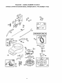
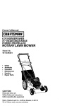
Owner's Manual
I:mAFTSMnNo
13.5 HP
ELECTRIC START
42" MOWER
6 SPEED TRANSAXLE
LAWN TRACTOR
Model No.
917,270411
, Safety
o Assembly
, Operation
Maintenance
Repair Parts
CAUTION:
Read and follow all
Safety Rules and Instructions
before operating this equipment.
For answers to your questions
about this product, Call:
1-800-659=5917
Sears Craftsman Help Line
5 am ,, 5 pro, Mon - Sat
Sears, Roebuck and Co., Hoffman Estates, IL 60179
Maintenance ............... i........................... 17
Service and Adjustments ............................
21
Storage .................................................. 27
Troubleshooting .......... _......................... 28
Repair Parts ............... :......................... 34
Parts Ordering ............ 'o.......... Back Cover
Warranty .................................................... 2
Safety Rules ............................................. 2
Product Specifications ........................... 5
Assembly .................................................. 8
Operation ....................................................11
Maintenance Schedule ......................... 17
o
I=.
LIMITED ONE YEAR WARRANTY ON CRAFTSMAN RIDING EQUIPMENT
For one (1) year from the date of purchase, if this Craftsman Riding Equipment is ma!ntalned, lubricated and tuned up according to the instructions in the owner's manual,
Sears will repair or replace, free of charge, any parts found to be defective in material or
workmanship.
This Warranty does not cover:
• Expendable items which become worn during normal use, such as blades, spark
plugs, air cleaners, belts, etc.
o Tire replacement or repair caused by punctures from outside objects, such as nails,
thorns, stumps, or glass.
- Repairs necessary because of operator abuse, negligence, improper storage or accident or the failure to maintain the equipment according to the instructions contained in
the owner's manual.
o Riding equipment used for commercial or rental purposes.
LIMITED 90 DAY WARRANTY ON BATTERY
For ninety (90) days from date of purchase, if any battery included with this riding equipment proves defective in material or workmanship and our testing determines the battery will not hold a charge, Sears will replace the battery at no charge. In-home warranty
service on your Craftsman riding equipment is available at no charge for 30 days from
the date of purchase. Please contact your nearest service center, After 30 days from the
date of purchase, warranty service is available by taking your Craftsman riding equipment to your nearest Sears Service Center. (In-home warranty service will still be available after 30 days from the date of purchase but a standard trip charge will apply). This
warranty applies only while this product is in the United States. This Warranty gives you
specific legal rights, and you may also have other rights which may vary from state to
state.
Sears, Roebuck and Co., D/817 WA, Hoffman Estates, IL 60179
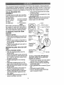
• Never carry passengers.
° Do not mow in reverse unless absolutely necessary, Always look down and
behind before and while backing,
. Be aware of the mower discharge direction and do not point it at anyone. Do
not operate the mower without either
the entire grass catcher or the guard in
place.
= Slow down before turning.
= Never leave a running machine unattended° Always turn off blades, set park..
ing brake, stop engine, and remove
keys before dismounting.
GENERAL OPERATION
e Read, understand, and follow all instructions in the manual and on the machine
before starting.
• Only allow responsible adults, who are
familiar with the instructions, to operate
the machine.
• Clear the area of objects such as rocks,
toys, wire, etc., which could be picked
up and thrown by the blade.
• Be sure the area is clear of other people
before mowing. Stop machine if anyone
enters the area.
O
ft.
W
O
UJ
U.,
03
O
14=
03
IL!
D.
O
=J
03
(5
;E
I=.
:Z:
m
03
n=
O
ii
U.I
5
(5
UJ
i-03
LL!
(5
(5
03
• Do not try to stabilize the machine by
putting your foot on the ground
o Do not use grass catcher on steep
slopes.
CHILDREN
• Turn off blades when not mowing.
• Stop engine before removing grass
catcher or unclogging chute.
• Mow only in daylight or good artificial
light,
• Do not operate the machine while under
the influence of alcohol or drugs.
° Watch for traffic when operating near or
crossing roadways.
o Use extra care when loading or unloading the machine into a trailer or truck.
SLOPE
Tragic accidents can occur if the operator
is not alert to the presence of children.
Children are often attracted to the
machine and the mowing activity, Never
assume that children wd|remain where
you last saw them.
o Keep children out of the mowing area
and under the watchful care of another
responsible adult.
o Be alert and turn machine off if children
enter the area.
o Before and when backing, look behind
and down for small children,
° Never carry children, They may fall off
and be seriously injured or interfere with
safe machine operation.
• Never allow children to operate the
machine,
• Use extra care when approaching blind
corners, shrubs, trees, or other objects
that may obscure vision.
SERVICE
OPERATION
Slopes are a major factor related to lossof-control and tipover accidents, which
can result in severe injury or death. All
slopes require extra caution. If you cannot
back up the slope or if you feel uneasy on
it, do not mow ito
DO:
o Mow up and down slopes, not across°
• Remove obstacles such as rocks, tree
limbs, etc.
° Watch for holes, ruts, or bumps. Uneven
terrain could overturn the machine. Tall
grass can hide obstacles.
o Use slow speed. Choose a low gear so
that you will not have to stop or shift
while on the slope_
o Follow the manufacturer's recommendations for wheel weights or counterweights to improve stability.
• Use extra care with grass catchers or
other attachments. These can change
the stability of the machine.
• Keep all movement on the slopes slow
and gradual Do not make sudden
changes in speed or direction.
o Avoid starting or stopping on a slope. If
tires lose traction, disengage the blades
and proceed slowly straight down the
slope_
DO NOT:
• Do notturn on slopes unless necessary,
and then, turn slowly and gradually
downhill, if possible.
. Do not mow near drop-offs, ditches, or
embankments. The mower could suddenly turn over if a wheel is over the
edge of a cliff or ditch, or if an edge
caves in.
° Do not mow on wet grass, Reduced
traction could cause sliding,
o Use extra care in handling gasoline and
other fuels, They are flammable and
vapors are explosive.
Use only an approved container.
Never remove gas cap or add fuel
with the engine running. Allow engine to cool before refueling, Do not
smoke.
Never refuel the machine indoors,
Never store the machine or fuel
container inside where there is an
open flame, such as a water heater.
o Never run a machine inside a closed
area,
• Keep nuts and bolts, especially blade
attachment bolts, tight and keep equipment in good condition.
° Never tamper with safety devices.
Check their proper operation regularly.
• Keep machine free of grass, leaves, or
other debris build-up. Clean oil or fuel
spillage. Allow machine to cool before
storing.
• Stop and inspect the equipment if you
strike an object. Repair, if necessary,
before restarting,
3
o Nevermakeadjustmentsor repairswith
the engine running.
manufa!cturer's
recommended
parts,
" Grass catcher components are subject
to wear, damage, and deterioration,
which could expose moving parts or
allow objects to be thrown. Frequently
check components and replace with
when n_cessa_
o Mower blades are sharp and can cut.
Wrap tl_e blade(s) or wear g!oves, and
use extI'a caution when servnclng them.
', Cheek I_rake operation frequently.
Adjust _nd service as required.
• Be sure the area is clear of other people
before mowing, Stop machine if anyone
enters the area.
. Never carry passengers,
• Do not mew in reverse unless absolutely necessary. Always look down and
behind before and while backing°
,, Never carry children. They may fall off
and be seriously injured or interfere with
safe machine operation.
,, Keep children out of the mowing area
and under the watchful care of another
responsible adult.
,' Be alert and turn machine off if children
enter the area.
• Before and when backing, look behind
and down for small children.
o Mow up and down slopes (15 ° Max), not
across.=
• Remove obstacles such as rocks, tree
limbs, _,tc.
• Watch for holes, ruts, or bumps.. Uneven
terrain could overturn the machine. Tall
grass can hide obstacles.
° Use slow speed. Choose a low gear so
that you will not have to stop or shift
while orLthe slope.
o Avoid starting or stopping on a slope. If
tires lose traction, disengage the blades
and proceed slowly straight down the
slope.
° Do notturn on slopes unless necessary,
and then, turn slowly and gradually
downhill, if possible,
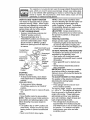
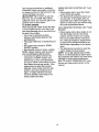
_kLook for this symbol to point out important safety precautions. It means CAUT IONI!! BECOME AWARE!!I YOUR SAFETY IS INVOLVED.
,_.WARNING: The engine exhaust from
this product contains chemicals known to
the State of California to cause cancer,
birth defects, or other reproductive hai'm.
•_kCAUTION: In order to prevent accidental starling when setting up, transporting,
adjusting or making repairs always disconnect spark plug wire and place wire where
it cannot contact spark plug.
4
GASOLINE
CAPACITY
AND TYPE:
1.25 GALLONS
UNLEADED
REGULAR
OILTYPE
API-SF/SG/SH):
SAE 30 (above 32°F)
SAE 5W-30
(below 32°F)
OIL CAPACITY:
3.0 PINTS
S-_RK
Champion
PLUG:
GAP: ,030")
CUSTOMER
STD361458
INTAKE:
.005"-.007"
EXHAUST: .009"-.011"
GROUND SPEED
(MPH):
FORWARD:
1sT
1,0
2ND
1.3
3RD
2,1
4 TM
4.0
5.1
1_6
TIRE PRESSURE:
FRONT:
REAR:
CHARGING
SYSTEM:
3 AMPS BATTERY
5 AMPS HEADLIGHTS
E3ATTERY:
AMP/FIR:
25
MIN. CCA:
190
CASE SIZE: U1R
27-35
_kWARNING: This tractor is equipped
with an internal combustion engine and
should not be used on or near any unimproved forest-covered, brush-covered or
grass-covered land unless the engine's
exhaust system is equipped with a spark
arrester meeting applicable local or state
laws (if any). If a spark arrester is used, it
should be maintained in effective working
order by the operator.
In the state of California the above is
required by law (Section 4442 of the
California Public Resources Code). Other
states may have similar laws. Federal
laws apply on federal lands. A spark
arrester for the muffler is available through
your nearest Sears Authorized Service
Center (See REPAIR PARTS section of
this manual).
3, '1
5 TM
6 TM
REVERSE:
RESPONSMBILITIES
, Read and observe the safety rules,
,, Follow a regular schedule in maintaining, caring for and using your tractor.
• Follow the instructions under "Maintenance" and "Storage" sections of this
owner's manual.
J19LM or
RJ19LM
VALVE
CLEAFLA,NCE:
E3LADEBOLT
TORQUE:
A Sears Maintenance Agreement is available on this product. Contact your nearest
Sears store for details.
14 PSI
12PSI
FT. LBS.
CONGRATULATIONS on your purchase
of a Craftsman Tractor. It has been
designed, engineered and manufactured
to give you the best possible dependability
and performance.
Should you experience any problem you
cannot easily remedy, please contact your
nearest Sears Authorized Service Center.
We have competent, well4rained technicians and the proper tools to service or
repair this tractor.
Please read and retain this manual. The
instructions will enable you to assemble
and maintain your tractor properly, Always
observe the "SAFETY RULES".
5
,
,
,..
,,,
.........
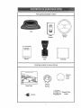
Parts Bag contents shown full size
Metal
Screws
(2) Sheet
#10-t6 × 1!2
©
3/8.24
(1) Locknut
(1) Large Flat Washer
(1) Knob
(1) Shoulder
Bolt 5/16-18
(1) Washer
17/32 x 1-3/16 x 12 Gauge
Washers
(2) Lock 114
(2) Hex Bolts 1/4-20 x 3/4
(2) Washers
9/32 x 5/8 x 16 Gauge
_
6
Nuts
1/4-20
(2) Hex
,-
i
ir_,l ,,,¸
Parts packed separately
r ...................
In carton
Seat
Steering
Wheel
Video
Cassette
L.,ul
-
Steering
Beot
Manual
........
.._
Parts Bag
Parts Bag contents not shown full size
.....
i
,
,
,
__
_.__>
teering
Insert
Wheel
Steering
Slope Sheet
Bushing
,
,_
(2) Keys
I---..--J
,
Steering Wheel
Adapter
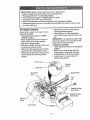
Your new tractor has been assembled at the factory with exception of those paris left
unassembled for shipping purposes To ensure safe and pi'oper operation of your tractor
all parts and hardware you assemble must be t ghtened securely. Use the correct tools
as necessary to insure proper tightness. Revlew the video cassette before you begin_
TOOLS REQUIRED FOR
ASSEMBLY
A socket wrenchset willmake assembly
easier. Standard wrench sizes you need
are listed below,
(1) 9/16" wrench
(2) 1/2" wrench
(1) Pliers
(1) Utility knife
(2) 7/t 6" wrenches
(1) Phillips Screwdriver
(1) Tire pressure
gauge
When right or left hand is mentioned in
this manual, it means, from your point of
view, when you are in the operating position (seated behind the steering wheel).
TO REMOVE
CARTON
TRACTOR
o Snap steering wheel insert into center
of stee_tng wheel.
o Remove protective materials from tractor hood and grill.
IMPORTANT" Check for and remove any
staples in!skid that may puncture tires
where tractor is to roll off skid,
FROM
UNPACK CARTON
o Remove all accessible loose parts and
parts boxes from shipping carton (See
page 6).
o Cut, from top to bottom, along lines on
all four corners of shipping cadon, and
lay panels flat.
, Check for any additional loose parts or
boxes and remove.
BEFORE ROLLING TRACTOR
OFF
SKID
ATTACH STEERING WHEEL
o Slide the steering bushing over the
steering shaft,
• Raise steering shaft forward until screw
holes in dash line up with steering bushing. Install two (2) sheet metal screws
and tighten securely.
° Position steering boot over steering
shaft.
o Place tabs of steering boot over tab
slots in dash and push down to secure.
° Slide steering wheel adapter onto upper
steering shaft.
o Position front wheels of the tractor so
they are pointing straight forward,
o Position steering wheel so cross bars
are horizontal (left to right) and slide
onto adapter°
• Assemble large flat washer and 3/8-24
Iocknut and tighten securely.
TO ROLL TRACTOR OFF SKID (See
Operation section for location and
function of controls)
o Press lift lever plunger and raise attachment lift lever to its highest position,
o Release parking brake by depressing
clutch/brake pedal.
o Place gearshift lever in neutral (N) position.
o Roll tractor forward off skid.
o Remove banding holding discharge
guard up against tractor,
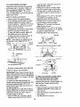
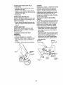
INSTALL SEAT
Adjust seat before tightening adjustment
Imob.
= Remove cardboard packing on seat pan.
o Place seat on seat pan and assemble
shoulder bolt, Tighten shoulder bolt
securely,
• Assemble adjustment knob and flat
washer loosely, Do not tighten.
o Lower seat into operating position and
sit on seat,
, Slide seat until a comfortable position is
reached which allows you to press
clutch/brake pedal all the way down.
° Get off seat without moving its adjusted
position.
o Raise seat and tighten adjustment knob
securely.
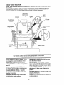
HOW TO SET UP YOUR TRACTOR
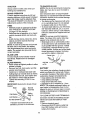
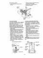
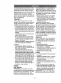
CONNECT
BATTERY
,&CAUTION: Do not short battery termF
rials by allowing a wrench or any other
object to contact both terminals at the
same time. Before connecting battery, remove metal bracelets, wristwatch bands,
rings, etc. Positive terminal must be connected first to prevent sparking from accidental grounding.
o Remove cardboard packing from seat
pan and lift seat pan to raised position.
o Open battery box door and remove protective plastic.
= Remove terminal protective caps and
discard.
° If this battery is put into service after
month and year indicated on label (label
located between terminals) charge bat.
tery for minimum of one hour at 6-10
amps°
o First connect RED battery cable to positive (+) terminal with hex bolt, flat washer, lock washer and hex nut as shown.
Tighten securely.
, Connect BLACK grounding cable to
negative (-) termina! with remaining hex
bolt, flat washer, lock washer and hex
nut. Tighten securely.
• Close battery box door. Open battery
box door for:
,, Inspection for secure connections
(to tighten hardware).
• Inspection for corrosion.
, Testing battery.
• Jumping (if required).
• Periodic charging.
Positive
Discard "lermtnal
(Red) Cable
Proctective Caps
Seat
Seat Pan
Shoulder
_
Bolt
F
_
_("_-
Adjustment Knob
Lock Washer
Flat Washer
Hex Bolt
Negative
(Black)
Seat
Batter
Door
9
.,_===== _k
frT---_'_l
/[
,k\_'C"_\_
_
FlatWasher
CHECK DECK
LEVELNESS
,I CHECKLIST
Fer beet cutting results, mower housing
should be properly teveled_ See '_TO
LEVEL MOWER HOUSING" in the
Service and Adjustments
section of this
manual,
PLEASE REVIEW THE FOLLOWING
CHECKLIST:
,/" All assembly instructions have been
completed.
# No remaining loose parts in carton
,/" Battery is properly prepared and
charged. (Minimum ! hour at 6 amps)o
/" Seat is adjusted comfortably and
tightened securely.
,/" All tires are properly inf!ated. (For
shipping purposes, the tires were
overinflated at the factor,,,).
v" Be sure mower deck is properly leveled
side-to-side/front-to-rear for best
cutting results. (Tires must be properly
inflated for leveling),
,," Check mower and drive belts. Be sure
they are routed properly around pulleys
and inside all belt keepers.
¢ Check wiring. See that all connections
are still secure and wires are properly
clamped_
CHECK FOR PROPER POSITION OF
ALL BELTS
See the figures that are shown for replacing motion and mower blade drive belts in
the Service and Adjustments sectoin of
this manual° Verify that the belts are routed correctly.
CHECK BRAKE SYSTEM
After you learn how to operate your tractor, check to see that the brake is properly
adjusted. See "TO ADJUST BRAKE" in
the Service and Adjustments section of
this manual.
WHILE LEARNING HOW TO USE YOUR
TRACTOR, PAY EXTRA ATTENTION TO
THE FOLLOWING IMPORTANT ITEMS:
#" Engine oil is at proper level.
,/ Fuel tank Is filled with fresh, clean,
regular unleaded gasoline.
,/ Become familiar with all controls - their
location and function. Operate them
before you start the engine.
,f Be sure brake system is in safe
operating condition.
10
Thesesymbolsmay appear on your tractor or in literature supplied with the product,
Learn and understand their meaning.
BATTERY
CAUTION OR
WARNING
ENGINE ON
ENGINE
OFF
IXI
FUEL
CHOKE
REVERSE
FAST
FORWARD
OIL PRESSURE
SLOW
OVER TEMP
LIGHT
LIGHTS ON
.@0
MOWER HEIGHT
PARKING BRAKE
LOCKED
UNLOCKED
MOWER LIFT
L
ATTACHMENT
CLUTCH ENGAGED
REVERSE
NEUTRAL
HIGH
LOW
PARKING BRAKE
®@@®@
KEEP AREA CLEAR
ATTACHMENT
CLUTCH DISENGAGED
IGNITION
SLOPE HAZARDS
(SEE SAFETY RULES SECTION)
I__1
HYDROSTATIC FREEWHEEL
(HydroModels only)
DANGER, KEEP HANDS AND FEET AWAY
11
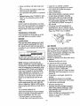
KNOW
YOUR TRACTOR
READ THIS OWNER'S MANUAL AND SAFETY RULES BEFORE OPERATING YOUR
TRACTOR
Compare the illustrations with your tractor to familiarize yourself with !he locations of
various controls and adjustments_ Save this manual for future reference°
Attachment
Clulch Lever
Arnmeter
Light
Ignition
Switch
\
Lift Laver
Plunger
ThrottIeChoke
Control _
Attachment Lift
Lever
Clutch/Brake
Pedal
Gearshift
Lever
•
Parking Brake
i
i
.......
Our tractors conform tothe safety standards of the American
National Standards Institute.
ii
,,
,i,
,,
,,
,i ,
ATTACHMENT CLUTCH LEVER: Used
to engage the mower blades, or other
attachments mounted to your tractor.
LIGHT SWITCH; Turns the headlights on
and off.
THROTTLE/CHOKE CONTROL: Used
for starting and controlling engine speed.
CLUTCH/BRAKE PEDAL: Used for
declutching and braking the tractor and
starting the engine_
PARKING BRAKE: Locks clutch/brake
pedal into the brake position.
L
,
, ,1
,,
GEARSHIFT LEVER: Seledts the speed
and direction of tractor.
ATTACHMENT LIFT LEVER: Used to
raise, lower, and adjust the mower deck or
other attachments mounted to your tractor.
LIFT LEVER PLUNGER; Used to release
attachment lift lever when changing its
position.
IGNITION SWITCH: Used for starting and
stopping the engine.
AMMETER: Indicates battery charging (+)
or discharging (-).
12
The operation of any tractor can result in foreign ob_c-"_s'°ihrown into the
eyes, which can result in severe eye damage. Always wear safety glasses or eye shields while operating your tractor or performing any adjustments or repairs, We recommend a wide vision safety mask over the
spectacles, or standard safety glasses.
,,
HOW TO USE YOUR TRACT,OR
Your tractor is equipped with an _perator
presence sensing switch. When engine
is running, any attempt by the operator to
leave the seat without first setting the
parking brake will shut off the engine.
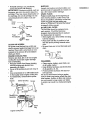
TO SET PARKING BRAKE
Depress clutch/brake pedal into full
"BRAKE" p'osition and hold,
,= Place parking brake lever in
"ENGAGED" position and release pressure from clutch/brake pedal. Pedal
should remain in "BRAKE" position
Make sure parking brake will hold tractor secure.
Attachment Clutch Lever
Position
Throttle/Choke
Control lever
"Disengaged"
Position
Clutch/Brake
Pedal "Drive"
Position
Parklng
Brake
"Engaged"
P0sition
Gearshift
"Disengag
Position
Lever
"Brake"
STOPPING
MOWER BLADES . To stop mower blades, move attachment clutch lever to "DISENGAGED"
position.
GROUND DRIVE • To stop ground drive, depress
clutch/brake pedal into full "BRAKE"
position.
o Move gearshift lever to neutral (N) position.
ENGINE
o Move throttle control to slow position.
NOTE_ Failure to move throttle control to
slow position and allowing engine to idle
before stopping may cause engine to
"backfire",
° Turn ignition key to "OFF" position and
remove key. Always remove key when
leaving tractor to prevent unauthorized
use.
. Never use choke to stop engine.
1,3
_
,
,
,
,,,
,
,
NOTE; Under certain conditions when
tractor is standing idle with the engine running, hot engine exhaust gases may
cause "browning" of grass. To eliminate
this possibility, always stop engine when
,_pping tractor on grass areas.
CAUTION. Always stop tractor completely, as described above, before leaving
the operator's position; to empty grass
catcher, etc.
THROTTLE CONTROL
Always operate engine at full throttle.
o Operating engine at less than full throttle reduces the battery charging rate.
• Full throttle offers the best bagging and
mower performance,
TO MOVE FORWARD AND BACKWARD
The direction and speed of movement is
controlled by the gearshift lever.
• Start tractor with clutch/brake pedal
depressed and gearshift lever in neutral
(N) posltiom
,, Move gearshift lever to desired position,
o Slowly release clutch/brake pedal to
start movement.
IMPORTANT: Bring tractor to a complete
stop before shifting or changing gears,
Failure to do so will shorten the useful life
of your transaxle
TO ADJUST MOWER cUTrlNG HEIGHT
The position of the attachment lift lever
determines the cutting height°
- Grasp lift lever.
,, Press plunger with thumb and move
lever to desired position.
The cutting height range is approximately 1-1/2 to 4". The heights are measured
from the ground to the blade tip with the
engine not running, These heights are
approximate and may vary depending
upon soil conditions, height of grass and
types of grass being mowed.
The average lawn should be cut to
approximately 2-1/2 inches during the
cool season and to over 3 inches during
hot months. For healthier and better
looking lawns, mow often and after
moderate growth.
° Forbest cuttingperformance,grass
over6 inchesin heightshouldbe
mowedtwice. Makethe first cut relativelyhigh;the secondto desired
height.
,, When p_usl_Ingor towing your tractor, be
sure gearshift lever is in neutral (N)
position.
• Do not push or tow tractor at more than
five (5) MPHo
NOTE: T_ protect hood from damage
when transporting your tractor on a truck
or a trailer, be sure hood is closed and
secured to tractor. Use an appropriate
means of tying hood to tractor (rope, cord,
etc.).
TO OPERATE MOWER
Your tractor is equipped with an operator
presence sensing switch. Any attempt by
the operator to leave the seat with the
engine running and the attachment clutch
engaged wfll shut off the engine.
o Select desired height of cut,
• Start mower blades by engaging attachment clutch control.
o TO STOP MOWER BLADES -.disen-
BEFORE
_"
Lilt Lever
High Position _
_l''_-_
"_',,
_'_-_.._/-
;,'
Low
Position
Lift Lever .7 //_::_
Attachment J(F_=N _._
. o./.
High Position/"---__
//I
THE ENGINE
CHECK ENGINE OIL LEVEL
• The engine in your tractor has been
shipped, from the factory, already filled
with summer weight oil
• Check engine oil with tractor on teve!
ground.
o Remove oil fill cap/dipstick and wipe
clean, reinsert the dipstick and screw
cap tight, wait for a few seconds,
remove and read oil level. If necessary,
add oil until "FULL" mark on dipstick is
reached, Do not overfill
• For cold weather operation you should
change oll for easier starting (See "OIL
VISCOSITY CHART" in the Maintenance section of this manual),
• To change engine oU, see the Maintenance section in this manual.
_gage attachment clutch control.
CAUTION. Do not operate the mower
without either the entire grass catcher, on
mowers so equipped, or the discharge
guard in place.
Attachment
STARTING
Qu rd
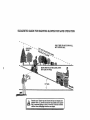
TO OPERATE ON HILLS
,_OAUTION: Do notdriveup ordown
hills with slopes greater than 15° and do
not drive across any slope. A slope guide
at the back of your manual is provided for
your use.
. Choose the slowest speed before starting up or down hills.
° Avoid stopping or changing speed on
hills.
o If slowing is necessary, move throttle
control lever to slower position.
• If stopping is absolutely necessary,
push clutch/brake pedal quickly to brake
position and engage parking brake.
• Move gearshift lever to 1st gear. Be
sure you have allowed room for tractor
to roll slightly as you restart movement.
• To restart movement, slowly release
parking brake and clutch/brake pedal.
• Make all turns slowly.
TO TRANSPORT
o Raise attachment lift to highest position
with attachment Iift control
14
ADD GASOLINE
° Fill fuel tank. Use fresh, clean, regular
unleaded gasoline with a minimum of
87 octaner (Use of leaded gasoline will
increase carbon and lead oxide
deposits and reduce valve life). Do not
mix oil with gasoline, Purchase fuel in
quantities that can be used within 30
days to,assure fuet freshness.
IMPORTANT: When operating in temperatures below 32°F(0°C), use fresh, clean
winter grade gasoline to help insure good
,_d weather starting.
WARNING: Experience Indicates that
alcohol blended fuels (called gasohol or
using ethanol or methanol) can attract
moisture which leads to separation and
formation of acids during storage. Acidic
gas can damage the fuel system of an
engine while in storage. To avoid engine
problems, the fuel system should be emptied before storage of 30 days or longer.
Drain the gas tank, start the engine and
let it run until the fuel lines and carburetor
are empty. Use fresh fuel next season.
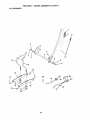
LIFT ASSEM
WARM WEATHER STARTING (50 ° F and
above)
, When engine starts, move the throttle
control to the fast position.
o The attachments and ground drive can
now be used. If the engine does not
accept the load, restart the engine and
allow it to warm up for one minute using
the choke as described above.
See Storage Instructions for, additional
Information. Never use engine or carburetor cleaner products in the fuel tank or per _
_nent damage may occur.
CAUTION: Fill to bottom of gas tank
filler neck° Do not overfill. Wipe off any
spilled oil or fuel. Do not store, spill or use
gasoline near an open flame.
TO START ENGINE
When starting the engine for the first time
or if the engine has run out of fuel, it will
take extra cranking time to move fuel from
the tank to the engine.
= Sit on seat in operating position,
depress clutch]brake pedal and set
parking brake.
,, Place gear shift lever in neutral (N) position.
o Move attachment clutch to "DISENGAGED" position.
o Move throttle control to choke position.
NOTE: Before starting, read the warm
and cold starting procedures below.
• Insert key into Ignition and turn key
clockwise to "START" position and
release key as soon as engine starts.
Do not run starter continuously for more
than fifteen seconds per minute. If the
engine does not start after several
attempts, move throttle control to fast
position, wait a few minutes and try
again° If engine still does not start,
move the throttle control back to the
choke position and retry.
COLD WEATHER STARTING (50 ° FAND
BELOW)
o When engine starts, allow engine to run
with the throttle control in the choice
position until the engine runs roughly,
then move throttle control to fast position. This may require an eng!ne warmup period from several seconds to sev.
eral minutes, depending on the temperature.
o The attachments can also be used dur-.
Ing the engine warm..up pedod.
NOTE; If at a high altitude (above 3000
feet) or in cold temperatures (below 32 F)
the carburetor fuel mixture may need to be
adjusted for best engine performance.
See "TO ADJUST CARBURETOR" in the
Service and Adjustments section of this
manual.
15
MOWING TIPS
• "Tirechains cannot be used when the
mower housing is attached to tractor.
, Mower should be properly leveled for
best mowing performance. See %0
LEVEL MOWER HOUSING" in the
Service and Adjustments section of this
manual.
• The left hand side of mower should be
used for trimming.
o Drive so that clippings are discharged
onto the area that has been cut. Have
the cut area to the right of the machine.
This will result in a more even distribution of clippings and more uniform cutting.
• When mowing large areas, start by turning to the right so that clippings will discharge away from shrubs, fences, driveways, etc. After one ortwo rounds,
mow in the opposite direction making
left hand turns until finished
= If grass is extremely tall, it should be
mowed twice to reduce load and possible fire hazard from dried clippings.
Make first cut relatively high; the second
to the desired height.
• Do not mow grass when it is wet. Wet
grass will plug mower and leave undesirable clumps. Allow grass to dry
before mowing.
• Always operate engine at full throttle
when mowing to assure better mowing
performance and proper discharge of
material, Regulate ground speed by se..
lecting a low enough gear to give the
mower the best cutting performance as
well as the quality of cut desired,
• When operating attachments, select a
ground speed that will suit tile terrain
and give best performance of the attachment being used.
16
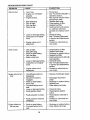
CUSTOMER
RESPONSIBILITIES
F'LL 'N DATES
AS YOU COMPLETE
_'_._.._.
.,/_'_'_'__._._
REGULAR SERVICE
_v
T
_, ,O'_i_'_O_,_'_,_d3__
_
.._.t_,q.?._._._
o
Sallbry
Engine
Change
Engine
Air Filler
N
Clean
Air Screen
Muffler/Spark
Replace
Clean
•
, ,..°
Arrester
OII Filler (If equipped)
Engine
COOling Fins
Replace
Spark
Replace
Air Filler Paper
Replace
Fuel
Plug
Cartridge
Filler
1 - Ch_g_
rnorm ellen when opqrmllng under t=heavy _o_d or In high arnblo_
_ZA Sarvl_{_ mo_. oft=n when _perattng In dirty or _u_ty _ondltlon_
3 _ II _qutpped with o!1 fllhlr, ¢h_ng_ o{I _live ry _0 hour=
GENERAL
tompi;r _oa
RECOMMENDATIONS
EACH
5 - II I={l_{pp_d with R_jul[mb_
_t_r_,
- Not r=qLd_d If =qLllppOd with malnl=n=nc{=, fl_=o to_ltoly
7 ,.'f'lghtan tront €_xlo i_vot bolt to _6 fL-tb_ maximum,
LUBRICATION
The warranty on this tractor does not cover
items that have been subjected to operator
abuse or negligence. To receive full value
from the warranty, operator must maintain
tractor as instructed in this manual° Some
adjustments will need to be made periodF
cally to properly maintain your tractor.
All adjustments in the Service and
Adjustments section of this manual should
be checked at least once each season,
= Once a year you should replace the
spark plug, clean or replace air filter, and
check blades and belts for wear; A new
spark plug and clean air filter assure
proper air-fuel mixture and help your
engine run better end lest longer.
BEFORE
_,l
Oil
Clean
?
...................
_
OII Level
E
Inspect
_
and Terminals/Recharge
x ioo,.o,,oo
o, o
Check
:
.....
'y
Clean
_"
DATES
J
R
_'_Oq'_
_:_,: _: _'_,_/_SERVICE
CHART
Spindle
Zerk
Zerk
-'rent
Front Wheel
Beadng Zerk
Wheel
Searing
Zerk
Engine
@Attachment }
Clutch
Pivot(s)
i
i
@SAE 30 or I0w30 MotorOIL
General Purpose Grease
.
Refer to Maintenance Engine Section
IMPORTANT: Do not oil or grease the
pivot points which have special nylon bearings, Viscous lubricants will attract dust
and dirt that will shorten the life of the selflubricating bearings. If you feel they must
be lubricated, use only a dry, powdered
graphite type lubricant sparingly,
USE
•
o
o
o
Check engine oil level.
Check brake operation,
Check tire pressure.
Check operator presence and interlock
systems for proper operation.
o Check for loose fasteners.
17
TO SHARPEN BLADE
NOTE: We do not recommend sharpening
blade, but if you do, be sure the blade is
balanced.
Care should be taken to keep the blade
balanced. An unbalanced blade will cause
excessive vibration and eventual damage
to mower and engine.
= The blade can be sharpened with a file
or on a grinding wheel. Do not attempt
to sharpen while it is on the mower.
= To check blade balance, you will need a
5/8" diameter steel bolt, pin, or a cone
balancer. (When L.,singa cone ba!ancer,
follow the instructions supplied with balancer).
NOTE: Do not use a nail for balancing
blade. The lobes of the center hole may
appear to be centered, but are not.
o Slide blade onto an unthreaded portion
of the steel bolt or pin and hold the bolt
or pin parallel with the ground. If blade
is balanced, it should remain in a horizontal position. If either end of the blade
moves downward, sharpen the heavy
end until the blade is balanced.
TRACTOR
Always obsewe safety rules when performing any maintenance.
BRAKE OPERATION
If tractor requires more than six (6) feet
stopping distance at high speed in highest
gear, then brake must be adjusted. (See
"TO ADJUST BRAKE" in the Service and
Adjustments section of this manual).
TIRES
. Maintain proper air pressure in all tires
(See "PRODUCT SPECIFICATIONS"
on page 5 of this manual).
, Keep tires free of gasoline, oil, or insect
control chemicals which can harm rubber.
• Avoid stumps, stones, deep ruls, sharp
objects and other hazards that may
cause tire damage.
NOTE: To seal tire punctures and prevent
flat tires due to slow leaks, tire sealant
may be purchased from your local parts
dealer. Tire sealant also prevents tire dry
rot and corrosion.
BLADE CARE
For best results mower blades must be
kept sharp. Replace bent or damaged
blades.
BLADE REMOVAL
• Raise mower to highest position to allow
access to blades.
Remove hex bolt, lock washer and flat
washer securing blade.
= Install new or resharpened blade with
trailing edge up towards deck as shown.
- Reassemble hex bolt, lock washer and
flat washer in exact order as shown.
Tighten bolt securely (27-35 R. Lbs.
torque).
Center Hale
Blade
518" Bolt
or Pin
BATTERY
Your tractor has a battery charging system
which is sufficient for normal use. However, periodic charging of the battery with an
automotive charger will extend its life.
° Keep battery and terminals clean.
• Keep battery bolts tight.
o Keep small vent holes open.
• Recharge at 6-10 amperes for I hour.
NOTE: The original equipment battery on
your tractor is maintenance free. Do not
attempt to open or remove caps or covers.
Adding or checking level of electrolyte is
not necessary.
10 CLEAN BATTERY AND TERMINALS
Corrosion and dirt on the battery and terminals can cause the battery to "leak"
power.
o Remove terminal guard.
= Disconnect BLACK battery cable first
then RED battery cable and remove
battery from tractor.
IMPORTANT: Blade bolt is Grade 8 heat
treated.
Blade
_
Mandrel
Flat Wasl
_
" _
Lock Washer....'_....._
Trailing
Edge Up
Hex Bolt (Grade8)*.
*A Grade 8 heat treated bolt can be
identified by six Itnes on '_hebolt head_
18
ENGINE
• Rinse the battery with plain water and
dry.
Clean terminals and battery cable ends
with wire brush until bright
o Coat terminals with grease or petroleum
jelly.
,, Reinstall battery (See "CONNECT
BATTERY" in the Assembly section of this
manual).
V-BELTS
Check V-belts for deterioration and wear
after 100 hours of operation and replace if
necessary. The belts are not adjustable.
Replace belts if they begin to slip from
wear.
,, Catch oil in a suitable container.
o Remove oil fill cap/dipstick. Be careful
not to allow dirt to enter the engine
when changing oil.
• Remove drain plug.
• After oil has drained completely, replace
oil drain plug and tighten securely,
o Refill engine with oil through oil fill dipstick tube. Pour slowly. Do not overfill.
For approximate capacity see "PRODUCT SPECIFICATIONS" on page 5 of
this manual.
o Use gauge on oil fill cap/dipstick for
checking level. Be sure dipstick cap is
tightened securely for accurate reading.
Keep oil at "FULL" line on dipstick.
TRANSAXLE
COOLING
Keep transaxle free from build_up of dirt
and chaff which can restrict cooling,
Oil Fltl
'-"'Cap/Dipstick
ENGINE
Oil Drain
LUBRICATION
Only use high quality detergent oil rated
with API service classification SF, SG or
SH, Select the oil's SAE viscosity grade
according to your expected operating temperature.
_,,"
Plug
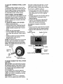
AIR FILTER
Your engine will not run properly using a
dirty air filter. Clean the foam pre-cleaner
after every 25 hours of operation or every
season.. Service paper cartridge every 100
hours of operation or every season,
whichever occurs first°
Service air cleaner more often under dusty
conditions,
o Remove knob(s) and covert
TO SERVICE PRE-CLEANER
NOTE: Although multi-viscosity oils
(5W30, 10W30 etc.) improve starting in
cold weather, these multi-viscosity oils will
result in increased oil consumption when
used above 32°E:Check your engine oil
level more frequently to avoid possible
engine damage from running low on oil.
Change the oil after every 25 hours of
operation or at least once a year if the
tractor is not used for 25 hours In one
o
•
•
°
Slide foam pre-cleaner off cartridge.
Wash it in liquid detergent and water,
Squeeze it dry in a clean cloth.
Saturate it in engine oil Wrap it in clean,
absorbent cloth and squeeze to remove
excess oil,
° If very dirty or damaged, replace precleaner,
o Reinstall pro-cleaner over cartridge,
• Reinstall cover and secure with knob(s).
year.
Check the crankcase oil level before starting the engine and after each eight (8)
hours of operation, Tighten oil fill cap/dipstick securely each time you check the oil
level.
TO SERVICE CARTRIDGE
o Remove cartridge nut.
• Carefully remove cartridge to prevent
debris from entering carburetor. Clean
base carefully to prevent debris from
entering carburetor,
• Clean cartridge by tapping gently on flat
surface. If very dirty or damaged,
replace cartridge.
TO CHANGE ENGINE OIL
Determine temperature range expected
before oil change. All oil must meet API
service classification SF, SG or SH.
o Be sure tractor is on level surface.
• Oil will drain more freely when warm.
19
o Reinstallcartridge,nut,precleaner,
cover andsecurewith knob(s).
IMPORTANT:Petroleumsolvents,suchas
kerosene,are not to be usedto cleanthe
cartridge.They may causedeteriorationof
the cartddgeoDo not oil cartridge_Do not
use pressurizedair to clean or dry cartridge.
Cover
Knob -'_
Cartridge
Nut
Foam
Pre°Cleaner
Cartridge
CLEAN AIR SCREEN
Air screen must be kept free of dirt and
chaff to prevent engine damage from overheating. Clean with a wire brush er compressed air to remove dirt and stubborn
dried gum fibers_
ENGINE COOLING FINS
Remove any dust, dirt or oil from engine
cooling fins to prevent engine damage
from overheating.
o Remove screws from blower housing
and Uft housing and dipstick tube
assembly off engine.
o Cover oil fill opening to prevent entry of
dirt.
• Use compressed air or stiff bristle brush
to thoroughly clean engine cooling fins.
• To reassemble, reverse above procedure.
CLEANING
o Clean engine, battery, seat, finish, etc.
of all foreign matter.
o Keep finished surfaces and wheels free
of all gasoline, oil, etc.
• Protect painted surfaces with automotive type wax.
We do not recommend using a garden
hose to clean your tractor unless the electrical system, muffler, air filter and carburetor are covered to keep water out. Water
in engine can result In a shortened engine
life.
air screen
Assembly
v-'i
/
_park
....
MUFFLER
Inspect and replace corroded muffler and
spark arrester (if equipped) as it could create a fire hazard and/or damager
SPARK PLUGS
Replace spark plugs at the beginning of
each mowing season or after every 100
hours of operation, whichever occurs first.
Spark plug type and gap setting are
shown tn "PRODUCT SPECIFICATIONS"
on page 5 of this manual.
IN-LINE FUEL FILTER
The fuel filter should be replaced once
each season, if fuel filter becomes
clogged, obstructing fuel flew te carburetor, replacement is required.
o With engine cool, remove filter and plug
fuel line sections.
° Place n.ew fuel filter in position in fuel
line with arrow pointing towards carburetor,
° Be sure there are no fuel line leaks and
clam.
Plug
Engine Cooling Fins
20
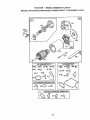
STEERING
._
_CAUTION: Beforeperformingany serviceor adjustments:
o
o
o
•
o
•
Depress clutch/brake pedal fully and set parking brake,
Place gearshift lever in neutral (N) position.
Place attachment clutch in "DISENGAGED" position.
Turn ignition key "OFF" and remove key.
Make sure the blades and all moving parts have completely stopped.
Disconnect spark plug wire from spark plug and place wire wllere it cannot come
in contact with plug,
• Disconnect front links from deck by
removing retainer springs.
, Raise lift lever to raise suspension
arms. Slide mower out from under tractor,
IMPORTANT: If an attachment other than
the mower deck is to be mounted on the
tractor, remove the front links.
TO INSTALL MOWER
o Raise attachment lift lever to its highest
position.
° Slide mower under tractor with discharge guard to right side of tractor.
o Lower lift lever to its lowest position.
o Install mower in reverse order of
removal instructions.
ro REMOVE MOWER
Mower will be easier to remove from the
right side of tractor.
• Place attachment clutch in "DISENGAGED" position.
• Move attachment lift lever forward to
lower mower to its lowest position.
o Roll belt off engine pulley.
• Disconnect clutch rod from clutch lever
by removing retainer spring.
o Disconnect antFswaybar from chassis
bracket by removing retainer spdng
• Disconnect suspension arms from rear
deck brackets by removing retainer
spdngs.
Clutch Lever
Retainer
Spdng
Clutch Rod
Suspension
Arms
Engine Pulley
Front
Link
Retainer Springs
(Both Sides)
prlngs
Sides)
Retainer
Spring
AntI-Swaybar
21
TO LEVEL MOWER HOUSING
Adjust the mower while tractor is parked
on level ground or driveway. Make sure
tires are properly inflated (See "PRODUCT SPECIFICATIONS").
If tires are
over or underinflated, you will not properly
adjust your mower.
SIDE-TO-SIDE ADJUSTMENT
°
°
Q
• Raise mower to its highest position.
o At the midpoint of both sides of mower,
measure height from bottom edge of
mower to ground. Distance "A" on both
sides of mower should be the same or
within 1/4" of each other,
• If adjustment is necessary, make adjustment on one side of mower only. '
° To raise one side of mower, tighten lift
link adjustment nut on that side.
° To lower one side of mower, loosen lift
link adjustment nut on that side.
NOTE: Each full turn of adjustment nut
will change mower height about 1/8",
Bottom
r---_.---,
of Cu__I,
o
o
o
equal ir_length. Both links should be
approximately 10-3/8"o
If links are not equal in length, adjust
one lint_to same length as other link.
"ToIowe_rfront of mower loosen nut "E"
on both_front links an equa number of
turns, i
When d,tstance "D" is 1/8" to 1/2" lower
at frontjthan !ear, tighten nuts "F"
againstltrunnuon on both front links.
'To raise front of mower, loosen nut "F"
from trunnion on both front/inks,
Tighteni nut °E" on both front links an
equal rill'j tuber of turns.
When distance "D" is 1t8" to 1/2" lower
at frontjthan rear, tighten nut "F" against
trunnion on both front links.
Rechedk side-to-side adjustment,
i
Mandrel
Bottom
Both Fro,_tLinks Should be Equal in Length
Curl
Ground Line
Suspension
Arm
Nut"E"
Trunnion-'_"_
• Recheck measurements after adjusting.
FRONT-TO-BACK ADJUSTMENT
IMPORTANT: Deck must be level side-toside. If the followingfront-to-back
adjustment is necessary, be sure to adjust both
front
links to-side.
equally
level side
so mower
Front Links
Trunnion
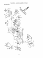
TO REPLACE MOWER BLADE DRIVE
BELT (See Illustration Next Page)
The mower blade drive belt may be
replaced without tools, Park the tractor on
level surface. Engage parking brake.
BELT REMOVAL -
will stay
To obtain the best cutting results, the
mower houstng should be adjusted so that
the front Is approximately 1/8" to 1/2"
lower than the rear when the mower is in
its highest position,
Cheek adjustment on right side of tractor.
Measure distance "D" directly in front and
behind the mandrel at bottom edge of
mower housing as shown.
= Before making any necessary' adjustments, check that both front links are
, Remove mower from tractor (See 'q'O
REMOVE MOWER" in thls section of
this manual).
• Work belt off both mandrel pulleys and
idler pulleys.
. Pull belt away from mower,
22
BELT INSTALLATION
-
o Make sure belt is in all pulley grooves
and inside all belt guides.
o Install mower in reverse orderof
removal instructions.
• Install new belt in reverse order of
removal.
Mandrel
Pulley
idler
Pulleys
\
Mandrel
Pulley
TO REPLACE MOTION DRIVE BELT
Park the tractor on level surface. Engage
parking brake. For assistance, there is a
belt installation guide decal on bottom side
of left footrest.
, Remove mower (See 'qO REMOVE
MOWER" in this section of this manua!.)
• Remove upper belt keeper.
o Remoye belt from stationary idler and
clutching idler.
• Pull belt slack toward rear of tractor.
Remove belt upwards fro m transaxle
pulley by deflecting belt keepers.
, Pull belt toward front of tractor and
remove downwards from around engine
pulley.
• Install new belt by reversing above procedure.
IMPORTANT: Make sure upper belt keeper is positioned properly between locater
tab.
TO ADJUST BRAKE
Your tractor is equipped with an adjustable
brake system which is mounted on the
right side of the transaxle.
If tractor requires more than six (6) feet
stopping distance at high speed in highest gear, then brake must be adjusted.
o Depress clutch/brake pedal and engage
parking brake.
o Measure distance between brake operat ng arm and nut "A" on brake rod.
o If distance is Other than 1-1/2", loosen
jam nut and turn nut "A" until distance
becomes 1-1/2", Retighten jam nut
against nut "A".
o Road test tractor for proper stopping
distance as stated above. Readjust if
necessary. If stopping distance ts still
greater than six (6) feet in highest gear,
further maintenance is necessary.
Contact your nearest authorized service center.
Engine
With Parklng Brake "Engaged"
Pulley _
Locater Tab
clutcht.g_
Idler
Nut "A"
Stationary
!/am
,d,
er
Nut
Transaxle..._
i°_Operating
Arm
23
1"--4
II .-_ I
Ir'-- Upper
Belt
11/ 1=t II
"ql
I[
II
!1 L,LII
II rl
i _11
Keeper
The other vehicle must also be a 12 volt
negative grounded system. Do not use
your tractor battery to start other vehicles.
TO ATTACH JUMPER CABLES • Connect each end of the RED cable to
the POSITIVE (+) terminal of each battery, taking care not to short against
chassis.
° Connect one end of the SLACK cable to
the NEGATIVE (-) terminal of fully
charged battery,
= Connect the other end of the BLACK
cable to good CHASSIS GROUND,
away from fuel tank and battery.
TO ADJUST STEERING WHEEL ALIGNMENT
If steering wheel crossbars are not horizontal (left to right) when wheels are positioned straight forward, remove steering
wheel and reassemble per instructions in
the Assembly section of this manual,
FRONT WHEEL TOE-IN/CAMBER
The front wheel toe-in and camber are not
adjustable on your tractor. If damage has
occurred to affect the front wheel toe-in or
camber, contact your nearest authorized
service center.
TO REMOVE WHEEL FOR REPAIRS
o Block up axle securely.
= Remove axle cover, retaining ring and
washers to allow wheel removal (rear
wheel contains a square key - Do not
lose).
o Repair tire and reassemble.
* On rear wheels only: align grooves in
rear wheel hub and axle. Insert square
key,
, Replace washers and snap retaining
dng securely in axle groove.
° Replace axle cover.
NOTE; To seal tire punctures and prevent
flat tires due to slow leaks, tire sealant
may be purchased from your local parts
dealer. Tire sealant also prevents tire dry
rot and corrosion.
TO REMOVE CABLES, REVERSE
ORDER o Remove BLACK cable first from chassis
and then from the fully charged battery.
o Remove RED cable last from both battedes,
PositiveTerminal
Negative Terminal
Washers
Retaining
Ring
Charged
Battery
Positive Terminal'.
Negative Terminal
Axle Cover
"_
Square Key
(Rear Wheel Only)
TO START ENGINE THAT HAS A WEAK
BATTERY
_,CAUTION:
Lead-acid batteries generate explosive gases. Keep sparks, flame
and smoking materials away from batteries. Always wear eye protection when
around battedes.
If your battery is too weak to start the
engine, it should be recharged° If "jumper
cables" are used for emergency starting,
follow this procedure:
IMPORTANT: Your tractor is equipped
with a 12 volt negative grounded system.
24
TO REPLACE HEADLIGHT BULB
• Raise hood.
= Pull bulb holder out of the hole in the
backside of the grill.
• Replace bulb in holder and push bulb
holder securely back into the hole in the
backside of the grill.
° Close hood,
ENGINE
Maintenance, repair, or replacement of the
emission control devices and systems,
which are being done at the customers
expense, may be performed by any nora
road engine repair establishment or individual. Warranty repairs must be performed by an authorized engine manufacturer's service outlet.
TO ADJUST THROTTLE CONTROL
CABLE
The throttle control has been preset at the
factory and adjustment should not be nec_
essary. Check adjustment as described
below before loosening cable. If adjustment is necessary, proceed as toUows:
o With engine not running, move throttle
control lever from slow to choke position. Slowly move lever from choke to
fast position.
', Check that holes "A" in governor control
lever and hole in governor plate line-up.
If holes "A" are not aligned, loosen
clamp screw and move throttle cable
until holes are aligned_ Tighten clamp
screw securely.
Governor
Governor
Control Lever
Control Plate
INTERLOCKS AND RELAYS
Loose or damaged wiring may cause your
tractor to run poorly, stop running, or prevent it from starting
• Check wiring. See electrical wiring diagram in the Repair Parts section of this
manual.
TO REPLACE FUSE
Replace with 30 amp automotive-type
plug-in fuse. The fuse holder is located
behind the dash.
TO REMOVE HOOD AND GRILL
ASSEMBLY
• Raise hood.
• Unsnap headlight wire connector.
,, Stand in front of tracton Grasp hood at
sides, tilt toward engine and lift off of
tractor.
• To replace, reverse above procedures.
Headlight
Wire
Connector
/ _
Holes "A"
25
Screw
Throttle
Cable
TO ADJUST CAFIBURFTOH
NOTE: The carburetor
on thisengineis
low emission, It is equipped with an idle
fuel adjusting needle with a limiter cap,
which allows some adjustment within the
limits allowed by the cap. Do not attempt
to remove the limiter cap. The timiter cap
cannot be removed without breaking the
adjusting needle.
The carburetor has been preset at the factory and adjustment should not be necessary. However, minor adjustment may be
required to compensate for differences in
fuel, temperature, altitude or load. If the
carburetor does need adjustment, proceed
as follows:
In general, tuming idle mixture valve in
(clockwise) decreases the supply of fuel to
the engine giving a leaner fuel/air mixture,
Turning the idle mixture valve out
(counterclockwise) increases the supply of
fuel to the engine giving a richer fuel/air
mixture,
IMPORTANT: Damage to the needle valve
and the seat in carburetor may result if
screw is turned in too tight.
o While sire noJamg mrot[ie Jever agamsl
idle speed screw, turn idle mixture valve
full travel clockwise then counterclockwise until engine runs rough. Turn valve
to a point midway between those two
positi(_nsoRelease throttle lever.ACCELERAT!ON TEST o Move throttle control lever from slow to
fast position° If engine hesitates or dies,
turn idle mixture valve out (counterclockWise) 1/8 turn. Repeat test and
continue to adjust, if necessary, until
engine accelerates smoothly.
High speed stop is factory adjusts& Do
not adjust--damage may result.
IMPORTANT: Never tamper with the
engine govemor, which is factory set for
proper engine speed, overspeeding the
engine above the factory high speed setting can be dangerous, if you think the
englne..governed high speed needs
adjusting, contact your nearest authorized
service center, which has proper equipment to make any necessary adjustments.
Idle Speed
Screw
PRELIMINARY SETTING , Air cleaner assembly must be assembled to the carburetor when making carburetor adjustments,
o Be sure the throttle control cable ls
adjusted properly (see above).
FINAL SETTING o Start engine and allow to warm for five
minutes. Make final adjustments with
engine running and shift/motion control
lever In neutral (N) positlon.
• Move throttle control lever to slow position. With finger, rotate and hold throttle
lever against idle speed screw. "[urn idle
speed screw to attain 1750 RPM.
Urnlter
26
Throttle
Lever
Immediatelyprepareyourti'actorfor storageat the endof the seasonor if the tractor will not be used for 30 days or more.
._,CAUTION: Never store the tractor with
gasoline in the tank inside a building
where fumes may reach an open flame or
spark. Allow the engine to cool before storing in any enclosure.
TRACTOR
Remove mower from tractor for winter
storage. This will allow you to clean it thoroughly. Remove all dirt, grease, leaves,
etc. Store in a clean, dry area.
o Clean entire tractor (See "CLEANING" in
the Maintenance section of this manual).
o Inspect and replace belts, if necessary
(See belt replacement instructions in the
Service and Adjustments section of this
manual),
o Lubricate as shown in the Maintenance
section of this manual.
o Be sure that all nu!s, bolts and screws
are securely fastened. Inspect moving
parts for damage, breakage and wear,
Replace if necessary.
* Touch up all rusted or chipped paint surfaces; sand lightly before painting,
BATTERY
o FUlly charge the battery for storage,
o After a period of time in storage, battery
may require recharging,
o To help prevent corrosion and power
leakage during long periods of storage,
battery cables should be disconnected
and battery cleaned thoroughly (see "TO
CLEAN BATTERY AND TERMINALS" in
the Maintenance section of this manual),
o After cleaning, leave cables disconnected and place cables where they cannot
come in contact with battery terminals.
o If battery is removed from tractor for
storage, do not store battei'y directly on
concrete or damp surfaces.
fuels (calied gasohol or using ethanol or
methanol) can attract moisture which
leads to separation and formation of acids
during storage, Acidic gas can damage the
fuel system of an engine while in storage.
= Drain the fuel tank.
o Start the engine and let it run until the
fuel lines and carburetor are empty,
• Never use engine or carburetor cleaner
products in the fuel tank or permanent
damage may occur.
° Use fresh fuel next season,
NOTE: Fuel stabilizer is an acceptable
alternative in minimizing the formation of
fuel gum deposits during storage. Add stabilizer to gasoline in fuel tank or storage
container. Always follow the mix ratio
found on stabilizer container. Run engine
at least 10 minutes after adding stabilizer
to allow the stabilizer to reach the carburetor. Do not drain the gas tank and carburetor if using fuel stabilizer.
ENGINE OIL
Drain oil (with engine warm) and replace
with clean engine oil, (See "ENGINE" in
the Maintenance section of this manual).
CYLINDER
• Remove spark plug(s).
o Pour one ounce of oil through spark
plug hole(s) into cylinder(s).
o Turn Ignition key to "STAR]" position for
a few seconds to distribute oil.
• Replace with new spark plug(s).
OTHER
• Do not store gasoline from one season
to another.
o Replac e your gasoline can if it starts to
rust. Rust and/or dirt in your gasoline
will cause problems,
• If possible, store your tractor indoors
and cover it to give protection from dust
and dirt..
• Cover your tractor with a suitable protective cover that does not retain mota,,
ture, Do not use plastic. Plastic cannot
breathe, which allows condensation to
form and cause your tractor to rust,
IMPORTANT; Never cover tractor while
engine and exhaust areas are still warm.
ENGINE
FUEL SYSTEM
IMPORTANT: It is important to prevent
gum deposits from forming in essential fuel
system parts such as carburetor, fuel filter,
fuel hose, or tank during storage° Also,
experience indicates that alcohol blended
27
CHART
TROUBLESHOOTING
,
i
PROBLEM
--
Will not start
o Out of fuel.
, Engine not "CHOKED"
properly.
o Engine flooded.
=
*
,
Bad spark plug.
Dirty air filter.
Dirty fuel filter.
Water in fuel.
• Loose or damaged wiring.
• Carburetor out of adjust..
ment.
• Engine valves out of
adjustment.
Hard to start
• Dirty air filter.
• Bad spark plug.
Weak or dead battery.
o Dirty fuel filter.
, Stale or dirty fuel.
= Loose or damaged wiring.
, Carburetor out of adjustment.
• Engine valves out of
adjustment.
Engine will not turn
over
o Clutch/brake pedal not
depressed.
° Attachment clutch is
engaged.
° Weak or dead battery.
° Blown fuse.
= Corroded battery terminals.
o Loose or damaged wiring.
• Faulty ignition switch.
, Faulty solenoid or starter.
o Faulty operator presence
switch(es).
Engine clicks but
will not start
_Wu
C0 RLRECTION
CAUSE
, Weak or dead battery.
° Corroded battery terminals.
28
o Fill fuel tank.
. See "TO START ENGINE" in
Operation section.
, Wait several minutes before
attempting to start.
• Replace spark plug.
o Clean/replace air tilter.
° Replace fuel filter.
o Drain fuel tank and carburetor, refill tank with fresh
gasoline and replace fuel filter.
• Check all wiring.
• See "To Adjust Carburetor"
in Service and Adjustments
section°
° Contact an authorized service center.
°
o
.
o
•
Clean/replace air filter.
Replace spark plug.
Recharge or replace battery.
Replace fuel filter.
Drain fuel tank and refill with
fresh gasoline.
• Check all wiring.
, See "To Adjust Carburetor"
in Service and Adjustments
section.
° Contact an authorized service center.
• Depress clutch/brake pedal.
o Disengage attachment
clutch.
• Recharge or replace battery.
° Replace fuse.
° Clean battery terminals.
= Check all wiring.
• Check/replace ignition
switch.
° Check]replace solenoid or
starter.
° Contact an authorized service center.
• Recharge or replace battery.
° Clean battery terminals.
TROUBLESHOOTING
PROBLEM
CHART
CAUSE
CORRECTION
Engine clicks but
will not start
(cont'd)
o Loose or damaged wiring.
• Faulty solenoid or starter.
+ Check all wiring.
o Check/replace solenoid or
starter,
Loss of power
o Cutting too much
grass/too fast.
° Throttle In "CHOKE" position.
o Build-up of grass, leaves
and trash under mower,
o Dirty air filter+
° Low oil level/dirty oil+
o Faulty spark plug.
+ Set in =Higher Cut" position/reduce speed,
• Adjust throttle control,
ii
o Dirty fuel filter.
• Stale or dirty fue!,
= Water in fuel
• Spark plug wire loose.
,, Dirty engine air
screen/fins.
, Dirty/clogged muffler.
• Loose or damaged wiring.
o Carburetor out of adjustmont.
= Engine valves out of
adjustment.
Excessive
vibration
= Worn, bent or loose blade,
o Bent blade mandrel.
o Loose/damaged part(s).
• Clean underside of mower
housing.
Clean/replace air tilter.
o Check oil level/change oil.
• Clean and regap or change
spark plug.
• Replace fuel filter.
, Drain fuel tank and refill with
fresh gasoline.
, Drain fuel tank and carburetor, refill tank with fresh gasoline and replace fuel filter.
• Connect and tighten spark
plug wire.
, Clean engine air screen/fins,
• Clean/replace muffler.
° Check all wiring.
, See "To Adjust Carburetor" in
Service and Adjustments
section+
o Contact an authorized service center.
• Replace
bolt.
I • Replace
o Tighten
Replace
, ,
blade. Tighten blade
blade mandrel.
loose part(s)+
damaged parts.
,,,
Engine continues to
run when operator leaves seat
with attachment
clutch engaged
, Fauliy operator-safety
presence control system.
• Check wiring, switches and
connections. If not
corrected, contact an authorized service center.
Poor cut - uneven
o Worn, bent or loose blade.
= Replace blade. Tighten blade
bolt,
= Level mower deck.
, Clean underside of mower
housing.
= Replace blade mandrel.
* Clean around mandrels to
open vent holes,
= Mower deck not level.
• Buildup of grass, leaves,
and trash under mower.
• Bent blade mandrel.
- Clogged mower deck vent
holes from buildup of
29
TROUBLESHOOTING
CHART
PROBLEM
CAUSE
CORRECTION
i
Poor cut - uneven
(cont'd)
grass, leaves, and trash
around mandrels.
i
Mower blades will
not rotate
° Obstruction in clutch
mechanism.
o Worn/damaged mower
drive belt.
, Frozen idler pulley.
[ • Frozen blade mandrel.
,
o Remove obstruction.
° Replace mower drive belt.
Replace idler pulley.
Replace blade mandrel.
,
i
i
Poorgrass
charge
dis-
• Engine speed too slow,
• Travel speed too fast.
= Wet grass.
• Mower
deck not level.
• Low/uneven tire air pressure.
• Worn, bent or loose blade.
• Buildup of grass, leaves
and trash under mower.
• Mower drive belt worn,
o Blades improperly
installed.
= Improper blades used.
• Clogged mower deck vent
holes from buildup of
grass, leaves, and trash
around mandrels.
Headlight(s) not
working (if so
equipped)
°
=
•
=
=
Switch is "OFF".
Bulb(s) burned out.
Faulty light switch.
Loose or damaged wiring.
Blown fuse,
" Place throttle control in
"FAST" position.
= Shift to slower speed.
* Allow grass to dry before
mowing.
, Level mower deck.
i ,_ Check tires for proper air
pressure.
Replace/sharpen blade.
= Tighten blade bolt.
: 'r Clean underside of mower
: housing.
Replace mower drive belt.
, Reinstall blades sharp edge
down.
o Replace with blades listed in
this manual.
o Clean around mandrels to
open vent holes.
• Turn switch "ON".
•
°
•
,
Replace bulb(s).
Check/replace
light switch.
Check wiring and connections.
Replace fuse.
i
Battery willnot
charge
Engine "backfires"
when turning
engine "OFF"
• Bad battery cell(s).
• Poor cable connections.
• Faulty regulator (if so
equipped).
o Faulty alternator.
° Replace battery.
° Check/clean all connection&
o Replace regulator.
° Engine throttle control not
set at "SLOW"
position for 30 seconds
before stopping engine.
. Move throttle control to
"SLOW" position and allow
to Idle for 30 seconds before
stopping engine.
3O
• Replace alternator.
31
32
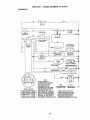
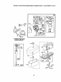
TRACTOR
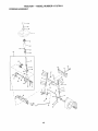
- - MODEL
NUMBER
917.270411
SCHEMATIC
BATTERY
_<_
.to
AMMETER
(OPTIONAL)
.._
)G
WH_
L(
SEAT SW1TCH
(NOT OCCUPIED)
I
IGNITION
SWITCH
GROUNDING
HEADLIGHTS
llaowt_
IGNITION SWITCH
pOSITION CIRCUIT "MAKE"
OFF
G +M÷ L
RUN/LIGHT B÷L
RUN
B+ L
START B _-L+ S
NONE
A+Y
NONE
NONE
NOTE
YOUR TRACTOR IS
EQUIPPED WITH A SPECIAL
ALTERNATOR SYSTEM,
THE LIGHTS ARE NOT
CONNECTED TO THE
NON-REMOVABLE
REMOVABLE
BATTERY, BUT HAVE THEIR
CONNECTIONS
CONNECTIONS
F_
OWN ELECTRICAL SOURCE,
BECAUSE OF THIS, THE
WIRING INSULATED CLIPS
BRIGHTNESS OF THE LIGHTS
WILL CHANGE WITH ENGINE
NOTE: IF WIRING INSULATED
SPEED, AT IDLE THE LIGHTS
CLIPS WERE REMOVED FOR
WiLL DIM. AS THE ENGINE IS
SERVICING OF UNIT, THEY
SPEEDED UP. THE LIGHTS
SHOULD BE REPLACED TO
WILL BECOME THEIR BRIGHTEST.
PROPERLY SECURE YOUR WIRING
33
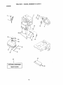
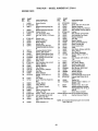
TRACTOR - - MODEL NUMBER 917.270411
ELECTRICAL
21
34
ELECTRICAL
KEY
PART
NO.
NO.
1
2
3
4
6
8
16
19
20
21
22
24
25
26
28
29
30
31
32
33
40
41
42
43
44
45
52
70
NOTE:
DESCRIPTION
144925
Battery 12 Volt 25 Amp
74760412
Bolt, Hax Head 1/4-20 L_ncx 3/4
STD551025
Washer
$TD551125
Washer
Nut
STD541025
156417
Case, Battery Mech Hinge
153664
Switch, Intertock Push-In
BTD551125
Washer, Lock
73350400
Nut, Hex, Jam 1/4o20 UNC
136850
Harness, Light Socket (Includes 4152J)
4152J
Bulb, Light
4799J
Cable, Battery, 6 Gauge, Red, 11'
146147
Cable, Battery, 6 Gauge, Red, W/16 Wire
108824X
Fuse, 30 Amp
4207J
Cable, Ground, 6 Gauge, Black, 12"
121305X
Switch, Plunger
140301
Switch, Ignition
124211X
Nut, Ignition
141226
Cover, Key Switch
109310X
Kay, Ignition
156442
Harness, Ignition
71110408
Bati, Flex Head, Fin. 1/4-20 x 1/2
131-r.r.r.r.r.r.r.r.r_]3
Cover, Terminal, Red
1456'73
Solenoid
73640400
Nut Keps BIk Hex 1/4-20 UNC
121433X
Ammeter Rectangular6 Amp
141940
Protection Wlm Loop
140413
Harness EngineB&S
All component dimensions give in U.S
1 Inch = 25.4 rnm
35
Inches
TRACTOR
- - MODEL
NUMBER
917.270411
CHASSIS AND ENCLOSURES
3O
17
21
22
26
'
'
29
14
19
33
10
34
38
14
36
TRACTOR .. - MODEL NUMBER
917.270411
CHASSIS AND ENCLOSURES
KEY
PART
NO.
NO.
1
2
3
4
5
6
7
8
9
10
11
13
14
15
16
17
18
19
21
22
24
25
26
28
29
30
31
33
34
35
37
38
39
54
140
145
161
--
NOTE:
160393
140356
17490612
STD551025
155272
155924X015
126842X
155138
161914X012
STD533710
155927
155934X010
17490608
74180512
STD541431
154986X558
126939×
17521312
122933X
124479X
STD523710
19131312
STD5414_7
140137
124029X
157584X558
136619
145244X553
145243;<558
STD533707
17490508
139886
139887
161464
158418
156524
161547
5479J
DESCRIPTION
Chassls Asm. 1.3:S'IMP
Drawbar Stretch
Screw Thdrol 3/6-16 x 3/4 Ty-tt
Washer 13/32 X 3/4 X 16 Ga
Dumper Hood/Dash
Saddle Slkscr FI1LT 6SP Dana
Shield Hr, Hood Lt
Clip Retainer Slide-On
Dash Slkscr l-pc
Dolt Rdhd Sqnk 3/8-16unc X 1
Panel Dash LH
Panel Slkser Dash RH
Screw Thdrol 3/8-16 x 1/2 Ty-tt
Screw Mach TRHD 5/16-18 unc x 3/4
Nut Keps 5/16-18 Unc
Hood Asm
Bumper Hood
Screw SItd Hex Hd W/PI Washer
Rivet Ratchet Nylon
Washer Nylon BIk 29 x 75 x 19
Bolt Fin Hex 3/8-16 uric x 1 Gr, 5
Washer 13/32 X 13/16 x 12 Ga
Nut Hax Lock W/lns_ 3/8-16 Uric
Grille Black
Lens Headlight Bar Clear
Fender Pnt LT W/o Shift
Bracket Fender Rep1109973x
Footrest Pnt Lh
Footrest Pnt Rh
Dol_Rdhd Sht Sqnk 3/6-16 x 3/4
Screw Thdrol 5/16-16 x 1,2
Bracket Asm Fvt LH MWR Rear
Bracket Asm Pvt RH MWR Rear
Screw
Bracket Suspension Front
Rod PivotChassis/Hood
Extrusion Hood
Plug Button BIk 359 Dla Choke
All component
dimensionsgivein U,S, inches
1 inch = 25,4 mm
37
TRACT(}R
- - MODEL
NU MBER
917.270411
GROUND DRIVE
57
7
"'+*+'"
1
++,======_
• "+_;++
+__++.
!7
. "
++;++..+.- _...:+-+
. I
",,
++ +.,_,
',
_
.
t ,,
,+ o +." o +_+
1
+,
72
I
116
/
I
4B
150
151
!
26
27
38
•
I HA_
GROUND
KEY
NO.
2
3
4
5
6
I Ui'i - - IVIUUr"L
I_UIVlIJr'H
_ I/.ZfU_.I
t
DRIVE
PART
NO,
146682
123666X
12000028
121520X
17490512
7
8
10
11
12
t3
14
15
18
162240
131679
STD561210
105701X
19151216
74550412
STD551125
74496544
STD523718
19
STD541437
21
22
24
25
26
27
26
29
30
31
32
34
35
36
37
38
39
40
106933X
130804
STD541237
106888X
STD551037
STD561210
146204
124236X
130807
127275X
STD523107
155071
120183X
STD551062
1572H
123674X
STD523727
4470J
KEY
NO.
DESCRIPTION
Transaxle Dana 43604 28
(See Breakdown)
Spring Return Brake T/a Zinc
Pulley Transaxle 18/20" tires
Ring Retainer # 5100-62
Strap Torque 30 Degrees
Screw Thdrol 5/18-18 X 3/4
Bracket Saddle Shilt T/a
Rod Shf Sdl LY/¥T Btr BIkZinc
Pin Cotter 1/8 X 1 Cad
Washer Plate Shf 386 Sq Hole
Washer 15/32 X 3/4 X 16ga
Boll 1/4-2Bunt Gr8 W/Patch
Washer Lock Hvy Helical 1/4
Bolt Hex FLGHD5/16-18Gr,5
Bolt Fin Hex 3/8-16 UNC x 1 G_
5
Nut Lock Hex W/Ins. 3/84 6
Une
Knob Rd 1/2-13 PIstcThds BIk
Rod Brake BIk Zinc 26 840
Nut Hex Jam 3/8-16 Unc
Spdng Rod Brake 2 00 Zinc
Washer 13/32 X 13/16 X 16 Ga
Pin Cotter 1/8 X 3/4 Cad
Rod Brake ParldngLt/Yt
Cap Brake Pa_ng Red
Bracket Mtg Traneaxle
Keeper BOlt LH LT 14 Ga
Bolt Hex Hd 5/16-18un0 X 3/4
ShaftAsm Pedal Foot LT/STLT
Beadng Nylon BIk 629 Id
Washer 21/32 X 1 X 16 Ga
Pin Roll 3/16 X 1"
Pulley Idler Rat
Bolt Fin Hex 3/8-16unc X 2..3/4
Spacer Split 395 X 59 Bzp
41
42
47
48
49
50
51
52
53
55
66
57
6B
59
61
62
63
154777
19131312
127783
154407
123205X
STD523715
STD541437
STD541431
105710X
105709X
STD523712
160855
127274X
140312
17490612
8883R
140186
64
65
66
70
72
74
75
76
77
76
112
116
71170764
STD551143
154778
134683
19132012
109502X
121749X
STD581075
123683X
121748X
t 9091210
72110610
148
149
150
151
159103
122052X
150935
19133210
NOTE:
39
PART
NO.
DESCRIPTION
Keeper Belt Idler Fool Proof
Washer 13/32 X 13/16 X 12 Ga
Pulley Idler V Groove Plastic
Betlcrank Asm Clutch
Retalner Belt Style Spring
Bolt Hex Hd 3/8-16unc X 1-1/2
Nut Crownlock 3/8-16 UNC
Nut Crown Lock 5/16-18
Unk Clutch 7 66
Spring Return Clutch 6 75
Bolt Fin Hex 3/8-16 uno x 1-1/4
V-Belt Gd Ddve 95 25
Keeper Belt RH LT Pnt/zinc 169
Keeper Belt Centerspan
Screw Thdrol 3/8-16x3/4 Ty4t
Cover Pedal BIk Round
Pulley Eng CI Mech 38dag
LT/YT
Bolt Hex 7/16-20x4 Gr 5
Washer Lock Hvy Hlcl Spr 7/16
Keeper Belt Engine Fool Proof
Guide Belt Mower Ddve RH
Washer !3/32 X 1-1/4 X 12 Ga
Spacer Axle
Washer 25,/32 X 1 1/4 X 16 Ga
E-dng #5133-75
Key Square 2 0 X 1845/1665
Washer25/32 X 1-5/6 X 16ga
Washer 9/32 X 3/4 X 10 Ga
BoK Rdhd Sq Neck 3/6o18 x
1,25
Spacer
Spacer, Retainer Pm
Bushing, Nylon Collared
Washer 13/32 x 2 x 10 Ga,
All componentdimensionsgivein U.S
inches 1 inch= 25.4 mm
TRACTOR
- - MODEL
NUMBER
STEERING ASSEMBLY
L
:: ......
'
t,
, ;"------ t
. .&-::[-[, - .-,
/
I
47
4O
917.270411
TRACTOR:
STEERING ASSEMBLY
KEY
NO,
1
2
3
4
5
6
7
8
9
10
11
13
15
17
18
19
20
22
23
25
26
27
28
29
30
32
36
37
38
39
40
41
42
43
46
47
62
65
66
67
68
PART
NO.
139768
154427
156483
157473
6266H
121748X
19272016
12000029
3366R
156438
STD551137
154779
73901000
156_15
57079
124035X
126684X
71200410
12790t
154406
126847)(
136874
19131416
17490612
STD561210
130465
155099
152927
139769
19133608
STD541537
104820X
124417X
121749X
121232X
6855M
156593
154790
154404
74781044
154429
- - MODEL
NUMBER
917.270411
DESCRIPTION
Steering Wheel
Axle Assembly STMP Dropped STL
Spindle Assembly, L.H
Spindle Assembly, R H.
Bearing, Race, Thrust, Hardened
Washer 25/32 x 1-5/8 × 15 Gauge
Washer 27/32 x 1-114x 16 Gauge
Rfng, Kltp
Beadng, Steering Column
Dragllnk Extended Stamped
Washer, Lock
BearingAxle STLT/GT
Nut, Lock, Flange 5/9-11 UNC
Shaft Assembly, Steering
Washer, Thrust 513 x .750 x 033
Support, Shaft
Washer, Shim 1/4 x 5(8 x .(].62
Screw, Hex Socket 1/4-20 x 5/8
Pittman Shatt Assembly
Bracket, Steedng
Suahlng, Link, Drag
Gear, Sector
Washer 13/32 x T/B x16 Gauge
Scraw, Thd., Roll. 5/8-16 × 3/4
Pin
Rod, T_e
J3ushfng,Steering
Screw
Insert, Sleeting Wheel
Washer 13/32 x 2_3/8 x 8 Gauge
GripooNut
Adaptor, Steering Wheel
Boat, Steering Shaft
Washer 25/32. x 1-1/4 x 16 Gauge
Cap, Spindle
Fitting, Grease
Kit Staering Asm Servlca
SpacerAxle
Beadng Arm Ptttman
Bolt, Fin Hex 5/8-11 UNC x 2-3/4
Axle, Brace
NOTE: All componentdimensionsglven inUS. Inches
1 inch= 25,4 mm
41
TRACTOR
- - MODEL
NUMBER
917.270411
ENGINE
4
33
23
29
OPTIONAL
EQUIPMENT
Spark Arrester
42
TRACTOR
KEY
NO,
1
2
4
13
14
15
15
23
29
31
32
33
35
37
38
40
44
46
62
72
78
81
PART
NO,
162144
17720410
137348
272293
13280324
13200300
STD551237
159880
137180
109202X
158990
123487X
17490512
137040
.......
124028)(
17490412
19091416
8TD551131
71070512
17490620
128861
- - MODEL
NUMBER
917.27041!
DESCRIPTION
Control Th/ch RH BIk Pd115 10
Screw Hex Thd Out 1/4-20;<5/8T
Engine B&S (See Breakdown)
Model No 28R707- H40-,EI
Muffler LT B&S 12/12 5/18 I-tP
Gasket Eng 1 313 Id Tin Plated
Nipple Pipe 3/8 Npt x 3"
Elbow Std 90 Degree 3/8-18 Npt
Washer Lock Ext Tooth 3/8
Shield Browning
Kit Spark Arrestor (Flat Scm)
Tank Fuel Front 1 25
Cap Asm Fuel Wlsym Vented
Clamp Hose elk
Screw Thdml 5/16-.18 x 3/4
Une Fuel 20"
Plug Oil Drain (Order From Engine Manufacturer)
Bush{ng Snap Nyt Blk Fuel Une
Screw Hexwsh Thdrol 1/4-20 x 3/4
Washer 9/32 x 7/8 x 16 ga
Washer Lock Hvy HIcl Spr 5/16
Screw Hex Hd Cap 5/16-18 X 3/4
Screw Thdml 3/8-16x1-1/4 TYTT
Nut Flange 1/4-20 StarlerNut
NOTE: AIt component dimensions given in US, inches
1 inch= 25.4 mm
43
TRACTOR
- - MODEL
NUMBER
917.270411
SEAT ASSEMBLY
KEY
NO.
1
2
3
4
5
6
7
8
9
10
11
12
13
PART
NO.
145122
140551
STD523710
19131510
145006
STD541437
124151X
17490616
19131614
155925
120098
121246X
121248X
KEY
NO.
DESCRIPTION
Seat
Bracket Pvt St
Bolt Fin Hex 3/8..16uno X 1
Washer Rat 13/32 X 1 X10Ga
Clip Push-In Hinged
Locknut Hex WiVVsh 3/8-16
Spring Seat Cprsn 2 250 BIk Zi
ScrewThdrol 3/8-16 X 1 Ty-tt
washer 13/32 X 1 X 14 Ge
Pan Seat
Knob Seat 112.,13
Bracket Mounting Switch
Bushing Snap BIk
14
1.5
16
17
21
22
24
25
PART
NO,
72050412
134300
121250X
123975X
153235
STD541431
19171912 '
127018X
DESCRIPTION
Ny150 Id
Bolt Rdhd Sht Nk 1/4_20xl,-1/2
Spacer Split 28x 96 Yel Zinc
Spring Cprsn 1 27 BIk Pnt
Nut Lock 1/4 Lge Fig Gr 5 Zinc
Bolt Shld 5116-15Unc
Nut LockHex'W/Ina
5/16-18
Washer 17132X 1-3/16 X 12 Ga
Bolt Shoulder 5/16*18 X 62
NOTE: All component dimensions given In U S Inches
1 Inch = 25.4 mm
44
I HAL;
I Ul'{
- - iViUUIZ, L I_Ui_g;,l'_
:d I/._/U_
I I
DECALS
6
3
4
11
21
10
12
2
13
M_
15
KEY
NO.
PART
NO.
1
2
3
4
6
273297
163209
163990
163991
133644
8
9
10
156857
163204
149516
11
156439
WHEELS
18
-I
_KEY
NO.
DESCRIPTION
Decal, Engine
Decal, Fender
Decal, Hood RH Crafts Sip LT
Decal, Hood LH Crafts Sip LT
Decal, Maint Oust Sears
Domesti
Decal, Oper Sd! Pit. Gear
Decal, Fender Craftsman White
Decal, Battery Dngr/Psn Eng
Acme
Decal, FancierEng/span]Dnger
& TIRES
4,10
PART
NO,
12
13
14
15
18
21
--*
-°
--
4900J
146046
163248
160396
133179
131265
157199
138311
164841
164842
KEY
NO.
PART
NO.
1
2
3
4
5
6
59192
55139
106222.X
59904
106732X427
278H
7
9040H
2
DESCRIPTION
Decal, Clutch/brakeEnglish
Decal, V.BelI Dr Sch Tractor
Decal, Panel Dash
Decal, V-Belt Sch
Decal, Mower Qc System
Decal, Llghlbox
Pad Footrest
Decal, Handle LftHeight Adjust
Manual Owners English
Manual Owners Spanish
DESCRIPTION
Cap Valve _ra
Stem Valve
Tire FTs 15X50 - 6 Serv]ca
Tube Front (Service Item Only)
Rim Asm 6" 1rent White Servlca
Fitting Grease (Front Wheel
Only)
0
9
10
11
106108X427
124635X
7152J
104757X
144334
Bearing Range (Front Wheel
Only)
Rim Asm 8" rear White SaUce
"13reR "is 18x9 5-8 C Service
Tube Rear (Service Item Only)
Cap Hub Axle BIk 1 50 X 1 00
Sealant, 3!re (10 oz° Tube)
NOTE: All component dimensions given in U.S_inches
1 Inch = 25A mm
45
TRACTOR
- - MODEL
NUMBER
917.270411
LiFT ASSEMBLY
7
8
/
/
/
!
/
J
3
13
2
6
5
13
19
20
19
13
32
46
I
/
I I Ill'IV
1 I,/I
I
-- -- 1111_/i_l.iI_
I_IVIIIII..II..I
| ill I ! mr..!
I.I"I
LIFT ASSEMBLY
KEY
NO.
1
2
3
4
5
6
7
8
11
12
13
15
16
17
18
19
20
31
32
PART
NO,
159460
159474
105767X
12000002
19211621
120183X
126631X
122365X
139865
139866
STD624008
127218
73350800
130171
73800800
139868
STD624008
140302
73540600
DESCRIPTION
Wire Asm Inner W/plunger
ShaftAsm Lift
Pin Groove 1 560 Zinc
E Ring #5133-62
Washer PItd 21/32 X 1 X 21ga
Bearing Nylon BIk 629 Id
Grip Handle Fluted BIk
Bulton Plunger Red
Link Lift LH
Link Lift RH
Retainer Spring
LinkFront
Nut Jam Hax 1/2-13 Unc
Trunnion Blk Zinc
Nut LockWAvsh 1/2-13unc
Ann Suspension Rear
Retainer Spdng Zinc
Beadng Pvt Lift Spherical
Nut Crownlock 3/8-24
NOTE: All component dimensions given In U.S, Inches
1 Inch = 25.4 mm
47
I •
TRACTOR
MOWER
- - I'_ODEL NUMBER
917.270411
DECK
68
58
21 22
,_23
24
\
2
16
28
29
,,.18
18
48
27
TRACTORi-
- MODEL
NUMBER
9'i7.270411
MOWER DECK
KEY
NO.
PART
NO.
1
2
8
144393
STD533107
138017
4
5
6
8
138440
STD624008
130832
950857
9
10
11
12
13
STD551137
140296
134149
129895
137645
14
15
16
17
19
19
20
21
22
23
24
25
26
27
28
128774
110485X
140329
72110610
72140505
132827
159770
STD541431
134.753
131267
105304X
123713X
110452X
130968
19111016
29
30
131491
157722
31
32
33
34
35
36
37
40
41
43
129963
153535
137266
STD533717
133835
131494
STD551037
STD541437
133551
140083
44
140988
KEY
NO,
DESCRIPTION
45
46
48
49
50
51
52
53
54
55
56
58
59
67
68
71
72
73
74
PART
NO,
DESCRIPTION
Retainer
Screw, Thd. Rol! 1/4-20 x 5/8
Washer, Hardened
Roller Assembly, Cam Follower
Boil,
Shoulder #10-24 Grade 5
Locknut
Bolt, Shoulder 5/16-16 UNC
Arm Assembly, Pad, Brake
Washer, Hardened
Arm, Idler
Spacer, R_talner
Spdng, Tomlon Brakes 42"
Guard, TuvIdler (94)
Knob, Custom Oval
V-Bait
Rod, Clutch, Primary, with Nlbs
Spdng, Return
Arm, Clutch, Secondary
Washer 25/32 x 1.5/6 x 16
Gauge
76
128903
Bolt, Shoulder 3/8-16 UNC ×
1.44
77
127846
Keeper, Spring
78
160571
Arm,Clutch, PIimary
79
127496
Bushing, Large, Brass
80
153701
Spring, Mower Clutch
81
73350600
Nut, HexJam 3/8-16 UNC
82
142026
Trunnion A_I. 94
83
120958;<
Washer, Sintered
84
156084
Keeper, Belt Idler
85
72140620
Bolt Rdhd Sq 3/8-16unc x 2-t/2
92
STD541437
Locknut, Hex WNv'sh 3/8-16
UNC
128
153390
Washer Felt
132
19132203
Spacer, Washer 13/32 LD. x 1..
3/80.D. x 1/4
141
6266H
Washer Tllrust .75 x 1.230
-130794
MandrelAesembly (Includes
Key Numbers 8-10, 12-15, 31
and 32)
- 145411
Mower Deck, Complete
Available Mulcher Plate Kit not includedwith tractor:
- 141112
Mulcher Close-out Rate Kit
Mower Housing
Bolt
Bracket Assembly, Sway Bar,
Front
Bracket Assembly, Sway Bar
Retainer Spring '
Arm, Suspension, Rear
Bolt, He× 3/8-24× 125 Grade
8
Washer, Lock
Washer, Hardened
Blade, Mulching
Bearing, Ball
Shaft Assembly, Mandrel,
Vented (Includes Key Number
6)
Housing, Mandrel, Vented
Bearing, Ball, Mandrel
Stripper, Vented Mower Deck
Bolt, Carnage 3/8-16 x 2..1/4
Bolt, Cardage 5/16-18 x 5/8
Bolt, Shoulder
Baffle, Vortex
Nut,Crowelock5/16-18UNC
StiffenerBracket
Bracket, Deltector
Cap, Sleeve
Spdng, Torsion,Deflector
Nut, Push
Shield, Deflector
Washer 11/32 × 5/8 x 16
Gauge
Rod, Hinge
Screw Thdrol Hex Heed Zinc
Mwr
Washer, Spacer
Pulley, Mandrel
Nut, Toplock, Flanged
Bolt
Fsstner, Christmas Tree
Pulley, ldler_ Flat
Washer 13/32 x 13/16 x 16 Ga.
Nul, Crownlock 3/8-16 UNC
Rod, Plvol, will] Ntbs
Rod, Clutch, Secondary, with
Ntbs
Guard, Mandrel, L.H.
$I"D624003
137729
133944
155066
131340
STD541410
139888
131845
133943
155046
122052X
140088
141043
162113
144200
142427
131870
127847
121746X
NOTE: All component
dimensionsgiven InUS_]nches
1 inch= 25,4 mm
49
TRACTOR
= ,"MODEL
NUMBER
917.270411
DANA TRANSAXLE - - MODEL NUMBER D4360-128
36
38
53
59
62
6t
23
50
TRACTOR -_- MODEL NUMBER
DANA TRANSAXLE
KEY
NO.
PART
NO.
1
2
3
4
5
160955
2274J
134400
105904X
160940
6
7
8
9
10
11
12
18
138235
108727X
148266
148269
2225..I
134793
148268
120415X
14
15
16
17
18
19
20
21
22
23
24
25
26
27
28
29
30
3I
32
33
34
35
142674
161563
161564
105909X
105910X
160942
160943
148267
138236
73810500
142676
2244J
105916X
120470X
110070X
142677
142681
124644X
108980X
120406X
134796
105925X
36
2228J
37
2231J
917.270411
- - MODEL NUMBER D4360-128
DESCRIPTION
Housing, Upper
Screw, Tapping, 1/4-20 X .734
Ball, Detent
Spdng, Detent
Screw, Tapping, No. 10-24 .X
°482
Assy, Kit. Shifter
V-Ring
Bearing, Flange
Seal, Oil
Ring, Retalr)lng
Assy, Kit, Shim, 625 Shalt
Bearing, Flange
Washer, Plain, .632 X 1.38 X
,o46
Key, Woodruff, No. 9
Assy, Kit, Input Shaft
Pinion, Bevel, 12T;
Ring, Retaining
Chain, 24 Pitches
Cover, Detent
Gear, Spur, 12T
Collar, C_utch
Assy, Kit, Clutch Keys
Nut, Lack, 5/16-24
Shaft, Intermediate
Key, Woodruff, Noo61
Ring, Retaining
Sprocket, 183"
Spacer, 1.131 X 1A5 X .494
Gear, Spur,37T
Gear, Spur,35T
Gear, Spur,30T
Gear, Spur, 25T
Gear, Spur, 22T
Gear, Spur, 19T
Washer, Plain, 640 X 1_37X
.061
Washer, Plain, ,632 X 1.00 X
.046
Washer, Plain, .632 X 1.00 X
031
KEY
NO,
PART
NO,
88
39
40
41
42
43
44
45
46
47
48
49
50
51
160944
124839X
120472X
105928X
161565
134394
120473X
142678
143697
124641X
106589X
120408X
105937X
22.26J
52
53
134401
2264J
54
55
56
57
58
58
60
61
62
63
64
65
66
67
68
69
160946
160947
160948
110071X
120952X
160949
160950
160951
120961X
7294J
108989X
160952
120954X
160953
138244
108996X
70
71
72
160954
120951X
120416X
DESCRIPTION
Assy, Gear, Comb, 12"I & 30T
Shaft, Idler
Spacer, .633 X .87 X .755
Sprocket, 9T
Gear, Bevel, 36T
Assy, Kit, Shim, _750 Shaft
Shaft, Drive
Gear, Spur, 12T
Gear, Spur, 15T
Gear, Spur, 20T
Gear, Spur,25T
Gear, Spur, 281"
Gear, Spur, 31T
Washer, Plain, .632 X 1.00 X
,060
Washer, Neoprene
Washer, Plain, .758 X 125 X
.031
Axle, LH
Gear, Miter, 12T, Spllned
Ring, Retaining
Gear, Spur,82T
Shaft, Cross
Gear, Miter, 12T, Idler
Axle, RH
Housing, Lower
Puck, Friction
Disc, Brake
Spacer, Brake Puck
Jaw, Brake
Pin, Dowel
Screw, Tapping, 5/16-18 X 2.35
Lever, Actuating
Washer, Rain, .321 X 1_0OX
.055
Bracket, Anti-Rotation
Puck, F_ction
Grease
NOTE: All component dimensions given In U.S. inches
1 inch = 25A mm
51
TRACTOR-
- MODEL
BRIGGS & STRATTON ENGINE-MODEL
NUMBER
917.270411
NUMBER 28R707, TYPE NUMBER 1140-E1
45
761
15
52
BRIGGS
& STRATTON
ENGINE-MODEL
NUMBER
28R707,
TYPE
NUMBER
_
,
'1_ REQUIRES SPECIAL TOOLS
TO INSTALL. SEE REPAIR
INSTRUCTION MANUAL,
[
f
i
284
I
171
535
53
445
:%.t_
1140.-E1
iii
,
TRACTOR - - MODEL NUMBER
BRIGGS & STRAT'rON ENGINE-MODEL
917.270411
NUMBER 28R707, TYPE NUMBER 1140-E1
240
265
209@
663
75
1044
304
455
_'
13331
100_
_7261
j
334
_A
TRACTOR
- - MODEL
BRIGGS 8=STRATTOH ENGINE-MODEL
NUMBER
917.270411
NUMBER 28R707, TYPE NUMBER 1140-E1
1090
121 CARBURETOR
1270
loe_
1380
95_'
634_
368 GASKET SET
KIT
so7@
_634A
116 _
lo4
137Q
los
142_
51
977 CARBURETOR GASKET SET
55
537_
_RIGGS
& STRATTON
KEY PART
NO, NO.
1
2
3
4
5
7
8
496413
399265
391086
494238
494240
271866
495735
9
10
11
12
27803
94621
280100
271916
271997
271996
94622
94239
498971
291675
94624
492326
222698
394661
394662
13
!5
16
20
22
23
24
25
394663
394664
26
27
28
29
391780
392331
391781
391782
391783
260924
299691
391296
490348
490469
32
33
34
35
94671
262246
262247
65906
36
37
40
41
42
45
26828
224502
221598
292260
494553
262248
46
50
51
212897
213819
272465
ENGINE-MODEL
NUMBER
DESCRIPTION
CylinderAssembly
Beadng, Cylinder
* Seal, OII
Base, Engine
Head, Cylinder
e* Gasket, Cylinder Head
BreatherAssembly
(Includes Mounting Gasket)
e" Gasket Valve Cover
Screw, Barns
"Tube,Breather
*Gaskat, Crankcase Cover, 1/64'
" Gasket, Crankc_ea Cover, r005"
" Gaslrst, Crankcase Cover, .009"
Screw, Cylinder Head
Plug, Oil Dra{n
Crankshaft
* Seal, OII
Screw, Serns, Base Mounting
Flywheel
Key, Flywheel
PlstonAssembly, Standard Size
Piston Assembly, .010'
Oversize
Piston Assembly, 020"
Oversize
PistonAssembly, .030"
Oversize
RingSet, Standard SIze
Ring Set, Standard Size,
Chrome
Ring Set, _OlO"Oversize
Ring Set, ,020" Oversize
Ring Sel, ,030"Oversize
Lock, Piston Pin
Pin, PIston, Standard SIze
Pin, Piston, _005' Oversize
Red, Connecting
Rod, Connecting, ,020"
Undersize
Screw, Connecting Rod
Valve, Exhaust
Valve, Intake
Intake Exhaust Valve
Spting, Valve
Guard, Flywheel
Retainer, Intake Valve
RoIocoll, Exhaust Valve
Retainer, Rotocoil
Tappet, Valve
KEY
NO.
PART
NO,
52
53
73
75
78
67
93
94
95
98
104
105
1_
105
121
123
125
127
130
131
133
137
138
141
142
272554
94637
224948
225136
94626
491323
281346
498030
94099
495808
231789
231855
231854
224540
469220
94913
498027
-. 224539
494379
494881
281165
291164
495097
497736
497737
146
171
186
18'7
168
201
209
216
219
222
224
22"?
230
232
240
265
94196
291051
493496
298049
94627
262767
260871
262766
490815
495611
94729
493935
94927
262785
394356
221536
""
*'*
_
Gear, Cam
Carburetor, Elbow
*"* Gasket, Carburetor
28R707,
TYPE
NUMBER
1140-E1
DESCRIPTION
e* Gasket, Carburetor
Stud, Carburstor Mounting
Screen, Rotating
Washer, Spring
Screw, Phillips
* Seal, Governor
Bushing, Throttta Shaft
Valve, Needle
** Screw, Throtlle
Screw, IdleAdjust
=" Pin, Roar Hinge
** Valve, Inlet Needle
*" Seat, Inlet
Valve, Choice
Carburetor Kit
Screw, Elbow Mounting
Carburetor
*" Plug, Welch (Said inKit Only)
Valve, Throttle
Shaft, Throttle
Roar, Carburetor
*"* Gasket, Float Bowl
*** Washer, FloatBowt
Shaft, Choke
"* Nozzle, Carburetor
Nozzle, Carburetor (High
Altitude)
Key, Timing
Nut, AlrCleaear
Elbow, Fuel Pipe
Usa, Fuel (Cut to Suit)
Screw, Seres
Link, Governor
Spdng, Governor
Link, Choke
Gear, Governor
Plate, GovemorControl
Screw, Hex Head
Lever Assembly, Govemor
Washer, Governor Crank
Spring, Governor Link
Filter; Fuel
Clamp, Casing
Included in Gasket Set (494241)
Included In Carburetor Kit (499220)
Included In both Carburetor tQ (499220),
and Carburetor Gasket Set (494,385)
Included in Valve Overhaul Gasket Set
NOTE: All component dimensions given tn U.S, Inches
1 Inch= 25A mm
56
BRIGGS
& STRATTON
KEY
NO,
PART
NO_
284
284A
304
305
305A
306
307
309
309
310
31t
333
934
337
346
956
358
363
38.3
445
455
467
474
482
503
510
523
524
525
535
537
544
552
562
592
601
614
615
616
634
635
646
657
663
666
668A
689
94903
94704
496280
94786
94881
224545
94930
491490
497595
94003
497608
492341
094731
602592
94896
494328
494241
19203
89838
496894
221561
493903
393474
93621
606000
497606
495230
281370
496113
2t2403
281106
497603
491986
94907
231978
93053
93306
263080
495157
494453
66538
224546
94906
94929
231109
280648
262820
ENGINE-MODEL
NUMBER
KEY
NO,
DESCRIPTION
Screw, Shoulder
Screw, Hex Head
Housing, Blower
Screw, Hex Head
Screw, Hex
Shield, Cyltnder
Screw, Seres
Cover, Cylinder Head
Motor, Starter
ThnJ Bolt
Brush Assembly
Armature, Magneto
Screw, Seres
Plug, Spark
Screw, Hex Head
Wire Assembly
Gasket Set
Puller, Flywheel
Wrench, Spark Plug
Cartridge, Air Cleaner
Cap, Rywbeel
Knob, Air Cleaner
Stator, Aitamator
Screw, Sems
Strap, Starter
StarterDdva Group
Dipstick, Oil
" Seal, Oil
Tube, OUFiller
Element, Filter
_* O-RIng, AIrCleaner
Armature, Starter
Bushing, GovemorCrank
Bolt, Governor Lever
Nut, Hex
Clamp, Fuel Pipe
Pin, Cotter
Retainer
Crank, Governor
* Seal, Spdng Assembly
Elbow, Spark Plug
Brace, AirCleener
Screw, Seres
Screw, HaxHead
Spacer
Spacer
Spring, Fdctlon
726
727
728
729
729A
741
757
758
759
761
763
801
802
803
842
84'7
851
869
870
871
28R707,
TYPE
PART
NO,
392134
490324
94951
281159
225170
262932
213998
399891
298909
94593
280104
394856
497605
497604
270920
*
496415
493880
261463
262924
261961
231218
872 281361
875 494237
677 393456
950 94642
965 94010
975 495933
977 494385
987 281166
**
1005
281400
1006
224413
1019
491252
1036
499362
1044
94673
1045
231828
1090
497607
1091
281364
1095
498539
2500
28R707-1140
-- 496050
NUMBER
1140-E1
DESCRIPTION
Gear, Ring
Cover, Starter
Screw Torx_
Clip, Lead Wire
Retainer, Wire
Gear, Timing
Unk, Counterweight
Counterweight Assembly
Pin, Counterweight
Screw, Counterweight
Gear
Cap, Ddva
Cap, End
Housing, Starter
Seal, Cap
Tube Assembly, Ol_
Terminal, Ignllion Cable
Seat, Intake Valve
Seat, Exhaust Valve
Guide, Exhaust Valve
Guide, Intake Valve, Brass
Cover, Air Cleaner
Body, Air Cleaner
Diode Assembly
Screw, Fuel Bowl
Nut, Hex
Bow], Float
Carburetor Gasket Set
Seal, Throttle Shaft
Fan, Flywheel
Retainer, Fan
Label Kit
Label, Kit, Emission
Screw, Hex Head
Extension, Crankshaft
Retainer, Brush
Cap, Ltmltar
Gasket Set, Valve Overhaul
Replacement Engine
Replacement Shortblock
RPM Settings: Low Speed: 1900-2100
High Speed: 3000-3200
Included in Gasket Set (494241)
Included tn Carburetor Kit (499220)
•"1'
Included in beth Carburetor Kit (499220),
and Carburetor Gasket Set (494385)
Included in Valve Overhaul Gasket Set
NOTE: All component dimensions given in U.S inches
1 inch = 254 mm
57
58
SUGGESTED
GUIDE FOR SnGHT_NG SLOPES
FOR SAFE OPERATION
ONLY RIDE UP AND DOWN HILL,
NOT ACROSS HILL
|
_
__recti°n
greater
never
the the
face.face
Make
Operate than
your 15°),
Tractor
up across
and down
of turns
slopes gradu(not
ally to prevent tipping or loss of control. Exercise extreme |
caution when changing direction on slopes.
|
°n Sl°Pes` ....
.
For the repair or replacement parts you need
delivered directly to your home
Call 7 am - 7 pm, 7 days a week
1=800=366=PART
(1-800-366-7278)
Para ordenar piezas con entrega a
demicilio - 1-800-659-7084
For in-house major brand repair service
Call 24 hours a day, 7 days a week
1-800-4-REPAIR
(1 .-800-473-7274)
Para pedir servicio de reparacidn a
domici|io - 1-800-676-5811
For the location of a Sears Parts and
Repair Center in your area
Call 24 hours a day, 7 days a week
1-800°488°1222
For information on purchasing a Sears
Maintenance Agreement or to inquire
about an existing Agreement
Call 9 am - 5 pm, Monday-Saturday
1-800-.827-6655
When requesting service or ordering
parts, always provide the following
information:
= Product Type
,, Part Number
Model Number = Part Description
America's
164841
03,06.98
RD
Repair SpeciaJ_st5
Printedin
U.S,A,