1
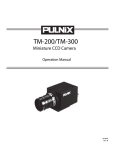
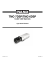
TMC-7DSP/TMC-6DSP
Color CCD Camera
Operation Manual
September 10, 1999
69-0059 Rev. A
Notice
The material contained in this manual consists of information that is proprietary to PULNiX America, Inc., and may only
be used by the purchasers of the product. PULNiX America, Inc. makes no warranty for the use of its product and assumes
no responsibility for any errors which may appear or for damages resulting from the use of the information contained
herein. PULNiX America, Inc. reserves the right to make changes without notice.
Warranty
All of our solid state cameras have a full three-year warranty. If any such product proves defective during this warranty
period, PULNiX America, Inc. will repair the defective product without charge for parts and labor or will provide a
replacement in exchange for the defective product. This warranty shall not apply to any damage, defect or failure caused
by improper use or inadequate maintenance and use.
Certifications
CE Compliance
The TMC-7DSP/TMC-6DSP has been certified to conform to the requirements of Council Directive 89/336/EC for
electromagnetic compatibility and to comply with the following European Standards:
Immunity:
EN500082-2/1995
Emissions:
EN55022:1995 Class A / CISPR 22:1993
All PULNiX products bearing the CE mark have been declared to be in conformance with the applicable EEC Council
Directives. However, certain factory installed options or customer requested modifications may compromise
electromagnetic compatibility and prohibit use of the CE mark. Please note that the use of interconnect cables that are not
properly grounded and shielded may affect CE compliance.
Contact the PULNiX Applications Engineering Department for further information regarding CE compliance.
FCC
This equipment has been tested and found to comply with the limits for a Class A digital device, pursuant to Part 15 of the
FCC Rules. These limits are designed to provide reasonable protection against harmful interference when the equipment
is operated in a commercial environment. This equipment generates, uses and can radiate radio frequency energy and, if
not installed and used in accordance with the instruction manual, may cause harmful interference to radio
communications. Operation of this equipment in a residential area is likely to cause harmful interference in which case the
user will be required to correct the interference at his own expense.
WARNING
Changes or modifications to this unit not expressly approved by the party responsible
for FCC compliance could void the user’s authority to operate the equipment.
TMC-7DSP/TM-6DSP Operation Manual
Printing: September 10, 1999
PULNiX America, Inc.
1330 Orleans Drive
Sunnyvale, CA 94089
Tel: (408) 747-0300
Tel: (800) 445-5444
Fax: (408) 747-0880
E-mail: [email protected]
www.pulnix.com
Table of Content
1 INTRODUCTION ..............................................................................................1
1.1
1.2
1.3
1.4
Product Description and Applications.................................................................................1
Features .............................................................................................................................1
Functional Options..............................................................................................................2
System Configuration .........................................................................................................3
2 INSTALLATION ................................................................................................4
2.1 Getting Started ...................................................................................................................4
2.1.1 Unpacking.................................................................................................................4
2.1.2 Components List.......................................................................................................4
2.1.3 Accessories and Options..........................................................................................4
2.2 Camera Setup ....................................................................................................................5
2.2.1 Connector Pin Configurations...................................................................................5
2.2.2 Power Supply and Power Cable Setup .....................................................................5
2.2.3 Attaching the Video Output.......................................................................................8
2.2.4 Attaching the Camera Lens ......................................................................................8
2.2.5 Back Focusing the Lens ...........................................................................................8
2.2.6 Auto-Iris Lens Setup (Optional) ................................................................................9
2.2.7 Monitor Display Mode...............................................................................................9
2.3 Camera Alinment and Adjustment......................................................................................9
2.3.1 Equipment ................................................................................................................9
3 OPERATION...................................................................................................11
3.1 Modes of Operation ..........................................................................................................11
3.1.1 Shutter Control Functions.......................................................................................11
3.1.2 Color Balance and Adjustment ..............................................................................11
3.1.3 Jumper Swich (JSW)*.............................................................................................12
3.1.4 White Balance Modes.............................................................................................12
3.1.5 Software Control Features......................................................................................14
3.2 Board Layout and Adjustment ..........................................................................................15
3.2.1 Top Board ...............................................................................................................15
3.2.2 Bottom Board..........................................................................................................15
4 SOFTWARE INSTRUCTIONS .......................................................................16
4.1 Software Installation .........................................................................................................16
4.1.1 Before Installing TMCDSP Software.......................................................................16
4.1.2 Installing TMCDSP Software ..................................................................................16
4.1.3 Uninstalling TMCDSP .............................................................................................16
4.2 Operating the Control Interface ........................................................................................17
4.2.1 Before Running TMCDSP.EXE ...............................................................................17
4.2.2 Shutter Mode Control .............................................................................................18
4.2.3 White Balance Control............................................................................................19
4.2.4 Gamma Control ......................................................................................................20
4.2.5 Back Light Compensation Control ..........................................................................20
4.2.6 Pedestal Control .....................................................................................................20
4.2.7 Aperture Control .....................................................................................................21
4.2.8 Gain Control ...........................................................................................................21
4.2.8 Y Gain Control ........................................................................................................21
4.2.9 Advanced Control ...................................................................................................21
4.2.10 Write Current Setting ............................................................................................21
i
Table of Contents
4.2.11 Read Setting.........................................................................................................23
4.3 Troubleshooting and FAQ .................................................................................................24
4.3.1 Main Control Dialog Box Does Not Open ...............................................................24
4.3.2 Advanced Controls Are Not Operational ................................................................24
5 TROUBLESHOOTING ...................................................................................24
5.1 Problems and Solutions....................................................................................................24
5.1.1 Symptom: No Video ................................................................................................24
5.1.2 Symptom: Dark Video.............................................................................................25
5.1.3 Symptom: Non-synchronized Video .......................................................................25
5.2 Information and Support Resources.................................................................................25
6 APPENDIX .....................................................................................................26
6.1 Specifications ...................................................................................................................26
6.1.1 Product Specifications ............................................................................................26
6.1.2 Physical Dimensions ..............................................................................................27
6.1.3 Glass Specifications ...............................................................................................28
6.1.4 C-Mount Specifications...........................................................................................28
6.1.5 Front End Detail......................................................................................................29
6.2 Imager Color Filters ..........................................................................................................30
6.1.1 Spectral Response with Complementary Mosaic Filter..........................................30
6.1.2 Complementary Stripe Filter...................................................................................30
6.3 Timing Chart .....................................................................................................................31
6.4 Block Diagram ..................................................................................................................31
ii
List of Figures
FIGURE 1.
TMC-7DSP/TMC-6DSP System Configuration ..............................13
FIGURE 2.
12P-02 Interface Cable (optional)...................................................16
FIGURE 3.
RS-232C Cable ..............................................................................17
FIGURE 4.
Shutter Control Settings .................................................................21
FIGURE 5.
TMCDSP Software Control Panel ..................................................24
FIGURE 6.
TMC-7DSP/TMC-6DSP Top Board ................................................25
FIGURE 7.
TMC-7DSP/TMC-6DSP Bottom Board...........................................25
FIGURE 8.
TMCDSP Control Dialog Box .........................................................27
FIGURE 9.
White Balance Control....................................................................29
FIGURE 10. Setting Values in “User” External White Balance Mode..................30
FIGURE 11. ASCII Text Format Example ...........................................................32
FIGURE 12. Physical Dimensions ......................................................................37
FIGURE 13. Camera Front End - Glass Specifications ......................................38
FIGURE 14. C-Mount\.........................................................................................38
FIGURE 15. Combination With “CS-Mount” Camera ..........................................39
FIGURE 16. Front End Detail..............................................................................39
FIGURE 17. Spectral Response .........................................................................40
FIGURE 18. Complementary Stripe Filter Diagram ............................................40
iii
September 10, 1999
TMC-7DSP/TMC-6DSP
Color CCD Camera
Operation Manual
1
INTRODUCTION
1.1 Product Description and Applications
The PULNiX TMC-7DSP/TMC-6DSP is a compact, high resolution color CCD camera offering the
latest in high performance Digital Signal Process (DSP) technology. It is available in both NTSC (TMC7DSP) and PAL (TMC-6DSP) formats.
Rugged construction and high resistance to vibration and shock make these cameras particularly
suitable for both industrial and CCTV surveillance applications. Offering superb color reproduction, the
TMC-7DSP/TMC-6DSP is an excellent choice for a wide range of applications such as
teleconferencing, machine vision, object recognition, medical systems, process monitoring, airborne
imaging and remote observation.
1.2 Features
•
High performance Digital Signal Processing (DSP)
PULNiX uses state of the art DSP technology which offers increased speed, greater efficiency and
specialization of function.
•
High sensitivity complementary color filter
The TMC-7DSP/TMC-6DSP uses complementary stripe color filters of Cy, Gr, Ye. More sensitive
than R, G, B primary color systems, a broader range of color variations are generated for
outstanding color fidelity.
•
NTSC (TMC-7DSP) or PAL (TMC-6DSP), Y/C (S-Video), and RGB output (TMC-7DSP
only)
Page 1
INTRODUCTION
In addition to the standard VBS output, the TMC-7DSP/TMC-6DSP cameras feature separate
outputs for the RGB signals with sync and Y/C output. RGB signals are output without the use of a
“breakout” module. Separate RGB and sync signals can be output directly from the camera via the
12-pin connector. Y/C output is available via the 6-pin connector. The Y signal also can be used for
auto iris control.
•
1/60 to 1/10,000 sec. programmable shutter and auto shutter
The auto shutter function on the TMC-7DSP/TMC-6DSP adjusts the shutter speed automatically to
maintain a wide dynamic range of video output (5 lux to 50,000 lux). This eliminates the need for
bulky, expensive auto iris lenses.
•
RS-232C external control
Many functions, including gain, white balance, gamma, aperture, hue control, and shutter control
can be controlled externally via a PC.
•
Anti-smear filter
Like all PULNiX color cameras, the TMC-7DSP/TMC-6DSP camera contains a filter to minimize
smear that can result when shooting a very bright object. Smear should only occur under extremely
bright and point light source conditions.
•
External sync (HD, VD sync) capability
The TMC-7DSP/TMC-6DSP accepts external HD-VD or composite sync.
•
Three Year Warranty
The CCD solid state image sensor allows the camera to maintain a superior performance level
indefinitely while requiring virtually no maintenance. PULNiX backs all of the TM Series cameras
with a three-year warranty.
Warning:
Unscrewing the camera cover or opening the camera in any way
will void this warranty.
1.3 Functional Options
Page 2
•
Standard or mini cylindrical remote head configurations (one meter separation)
•
Custom remote imager lengths
TMC-7DSP/TMC-6DSP Color CCD Camera
INTRODUCTION
1.4 System Configuration
Figure 1 (below) presents a typical system configuration.
FIGURE 1.
TMC-7DSP/TMC-6DSP System Configuration
Power
Ext. Sync
Integration
Video Output*
Auto-Iris Lens
(optional)
OPTION SHUTTER PWR/RGB
78
56
VIDEO
MODE
1
Computer with
Frame Grabber
Board
TMC-7DSP/TMC-6DSP Color CCD Camera
2
3
2 34
9 01
4
AWB
Monitor
* Video Output is the
same as BNC connector
Page 3
INSTALLATION
2
INSTALLATION
The following instructions are provided to help you to set up your video camera system quickly and
easily. It is suggested that you read through these instructions prior to unpacking and setting up your
camera system
2.1 Getting Started
2.1.1 Unpacking Instructions
It is recommended that the original packing cartons for the cameras and lenses be saved in case there is
a need to return or exchange an item. It is also recommended that any equipment being sent to another
location for field installation be bench tested to assure that everything is fully operational as a system.
2.1.2 Components List
Please begin by checking your order against the Components List (below) to assure that you have
received everything as ordered, and that nothing has been overlooked in the packing materials. If any
item is missing, please contact your PULNiX representative immediately.
•
TMC-7DSP/TMC-6DSP camera
•
TMC-7DSP/TMC-6DSP data sheet
2.1.3 Accessories and Options
Following is a list of additional accessories and options that may be recommended or required for your
particular application. Please check with your PULNiX representative prior to the installation of your
video system to determine what you might need.
Page 4
•
CamCom TMC7DSP/6DSP Software
•
RS-232C cable
•
K25-12, K-50-12, or PD-12P power supply
•
12P-02 power cable
•
DSP-2YC, Y/C output cable with RS-232
•
CBL-2R-7D, RGB output cable (for use with TMC-7DSP only)
•
TMC-7DSP/TMC/6DSP Operation Manual
TMC-7DSP/TMC-6DSP Color CCD Camera
INSTALLATION
2.2 Camera Setup
2.2.1 Connector Pin Configurations
2.2.1 (a)
12-Pin Connector
1
The TMC-7DSP/TMC-6DSP has a 12-pin connector for power input. Pin #1 is
Ground and Pin #2 is +12V DC. The other pins handle a number of other input
and output functions, as detailed below.
2
3
Description
Pin
Description
1
GND
7
Ext. Vd
2
+12V DC
8
GND
3
GND
9
Ext. Hd
4
Video out (VBS)
10
R out (TMC-7DSP only)
5
GND
11
G out (TMC-7DSP only)
6
Sync out
12
B out (TMC-7DSP only)
2.2.1 (b)
6
7
12
5
6
6-Pin Connector
The TMC-7DSP/TMC-6DSP has a 6-pin connector for RS-232C communication
and Y/C. A mating 6-pin connector (PC-6P) can be obtained from PULNiX.
1
5
Standard
2
4
8
10
11
4
Pin
9
3
Pin
Description
1
RS-232 RX
2
RS-232 TX
3
NC (12V DC opt.)*
4
Y (video)
5
C
6
GND
* For Pin #3, 12V DC is optional for auto iris control.
2.2.2 Power Supply and Power Cable Setup
2.2.2 (a)
Power Supplies
The TMC-7DSP requires 12 V DC. The 12pin connector is located at the rear of the camera. PULNiX
recommends the following power supplies:
K25-12
110V AC/12V DC
2.1A power supply
K50-12
110V AC/12V DC
4.2A power supply
PD-12P
110V AC/12V DC
0.5A power supply
TMC-7DSP/TMC-6DSP Color CCD Camera
Page 5
INSTALLATION
For users providing power through the 12-pin connector, the PD-12P power supply is available with the
12-pin mating connector already attached to the leads from the power supply. The PD-12 power supply
can be connected to the PULNiX power cable via a terminal strip or directly.
When wiring the PD-12 power supply directly, please note the following:
•
Twist the lead ends together and tin solder for strength and electrical continuity.
•
Use shrink tubing or a similar insulator to prevent exposed leads from touching.
•
The +12V lead is marked with a red stripe or white lettering; be sure not to reverse the leads.
•
Properly insulate all connections to prevent shorting.
2.2.2 (b)
PULNiX Power Cables
If you are using PULNiX power cables, such as the 12P-02, KC-10, etc., please refer to the pin-out
diagram. The color coded leads use Grey for Ground and Yellow for +12V DC.
FIGURE 2.
12P-02 Interface Cable (optional)
+12 V
GND (Gray)
Power (Yellow)
Video Out (Red Coax)
HD In (White Coax)
VD In (Black Coax)
12P-02 Interface Cable
Pin#
Lead Color
Function
Pin#
Lead Color
Function
1
Gray
GND
7
Black coax signal
Ext. Vd
2
Yellow
+12VCD
8
White coax shield
GND
3
Red coax shield
GND
9
White coax signal
Ext. Hd
4
Red coax signal
Video out(VBS)
10
Brown
R out*
5
Orange coax shield
GND
11
Blue
G out*
6
Orange coax signal
Sync out
12
Black coax shield
B out*
* Not recommended for RGB Output
Note:
2.2.2 (c)
Make sure that the unused leads are not touching and that there is no possibility that
the leads could short due to exposed wires.
“K” Series Power Supplies
Attach the 110V line cord to the two terminals marked “AC”. Do not plug the cord into a 110V AC
socket until later in the procedure. Next, attach the Grey and Yellow leads of the power cable to the
Page 6
TMC-7DSP/TMC-6DSP Color CCD Camera
INSTALLATION
Ground and 12V DC terminals respectively. Be sure to replace the plastic terminal guard on the power
supply at this time.
Note:
2.2.2 (d)
FIGURE 3.
The “K” series power supplies are designed primarily for OEM users who will be
mounting the power supply inside a protective enclosure. For use in exposed situations,
the DC-12N and PD-12 are recommended.
CBL-2R-7D RGB and Video Output Cable
CBL-2R-7D
RED
GREEN
BLUE
SYNC
C. Video
TMC-7DSP/TMC-6DSP Color CCD Camera
Page 7
INSTALLATION
2.2.2 (e)
FIGURE 4.
DSP-2YC RS-232 Control and Y/C Output Cable
DSP-2YC Cable
PC
RX
RS-232
TX
Ground
COM
PC COM
OR
Frame
Grabber
PIN1
DCD
PIN2
RxD
PIN3
TxD
PIN4
DRT
PIN5
GND
PIN6
DSR
PIN7
RST
NC
PIN8
CTS
NC
PIN9
RI
YEL
GRY
BLU
Page 8
Monitor
TMC-7DSP/TMC-6DSP Color CCD Camera
INSTALLATION
2.2.2 (f)
RS-232C-9 Communication Cable and Connector (optional)
The TMC-7DSP/TMC-6DSP camera’s built-in microcomputer chip (CPU) can be controlled by an
external RS-232C interface. The RS-232C-9 cable (Figure 5, “RS-232C-9 Cable”) connects to the 6pin connector on the rear of the camera. The internal CPU controls the TMC-7DSP/TMC-6DSP
camera’s operation mode and DSP parameter changes. Contact PULNiX for the TMC-7DSP/TMC6DSP software diskette.
FIGURE 5.
RS-232C-9 Cable
6-PIN CONNECTOR
2.2.2 (g)
D-SUB 9-PIN CONNECTOR
RXD
PIN 2
PIN 1
DCD
TXD
PIN 2
PIN 2
RXD
+12V
PIN 3
PIN 3
TXD
Y out
PIN 4
PIN 4
DTR
C out
PIN 5
PIN 5
GND
GND
PIN 6
PIN 6
DSR
PIN 7
RTS
PIN 8
CTS
PIN 9
RI
Building Your Own Power Cable
Consult the pin-out for the camera purchased. Connect the Ground and +12V power leads of the PC12P power connector (Part #PC-12P) to Pin #1 and Pin #2, respectively (power must be DC regulated,
and of sufficient current to properly power the camera).
TMC-7DSP/TMC-6DSP Color CCD Camera
Page 9
INSTALLATION
2.2.2 (h)
Attaching the Power Cable to the Connector
The 12-pin connector is keyed and will only fit in one orientation. Rotate the connector while applying
slight pressure until the keyways line up. Press the connector into place until firmly seated.
The power cord may now be plugged into the 110V AC socket, and the camera powered up.
2.2.3 Attaching the Video Output
Most users utilize the BNC connector for video output from the camera. Connect the output from the
camera to the input of your monitor, VCR or switching device. The input of the monitor should be
balanced for 75Ω termination. Standard RG-59 type coaxial cable should carry a full video signal for up
to 500 feet.
Users wishing to output the video and input the power and sync to a camera over a single cable can use
the PULNiX multi-conductor cables, such as the 12P-02, the KC-10, etc. The mini coaxial leads in
PULNiX multi-conductor cables are designed for short runs of no longer than 100 feet.
Note: Make sure that no extraneous wires are visible which could cause a short.
2.2.4 Attaching the Camera Lens
The TMC-7DSP/TMC-6DSP camera accepts 1/2" or larger format size C-mount lenses. To attach the Cmount lens to the camera, carefully engage the threads and rotate the lens clockwise until it firmly seats
on the mounting ring. Do not force the lens if it does not seat properly. Please note that some lenses with
extremely long flangebacks may exceed the mounting depth of the camera.
2.2.5 Back Focusing the Lens
To backfocus the TMC-7DSP/TMC6DSP camera, first attach a C-mount lens
in the lens mount. Be sure that the lens is
properly mounted.
Back focus ring
Set the lens focus to infinity (if the lens is
a manual iris, set the iris to a high f-stop
Back focus 2 ft.
while still retaining a well-illuminated
image). Obtain the best focus possible at
this setting, then loosen the three miniature hex head set screws locking the focus ring in place. Now
turn the entire lens and focus ring assembly back and forth until the best image is obtained. Tighten the
focus ring set screws. Your backfocus is now set.
2.2.6 Auto-Iris Lens Setup (Optional)
The auto-iris option allows auto-iris lenses with full video input to be used with the PULNiX TMC7DSP/TMC-6DSP via the 6-pin connector located on the back of the camera. A mating 6-pin connector
(PC-6P) may be obtained from PULNiX. See Section 2.2.1 (b), “6-Pin Connector”, on page 5 for
connections.
Page 10
TMC-7DSP/TMC-6DSP Color CCD Camera
INSTALLATION
Note:
Make sure that the power is removed from the camera before connecting or
disconnecting the auto-iris lens. There is a small chance that damage could occur to
the auto-iris lens by plugging or unplugging it while the camera is powered up.
Power down the camera before installing the auto-iris lens. Point the camera at a light area and then
quickly towards a darker area. If everything is working properly, the iris should adjust for the light
change.
2.2.7 Monitor Display Mode
For monitoring real time video, connect the video output to a video monitor or other device.
2.3 Camera Alignment and Adjustment
2.3.1 Equipment
2.3.1 (a)
Light Source for Test Chart
Pattern Box PTB-500 (90-130V)
PTB-220 (190-240V) (not used in the U.S.)
2.3.1 (b)
Video and Gamma Adjustment
TMC-7DSP/TMC-6DSP Color CCD Camera
Page 11
OPERATION
2.3.1 (c)
Color Bar Chart for Color Adjustment
YL
2.3.1 (d)
CY
G
W
MG R B
Signal Adjustment
Vector Scope
Waveform monitor
Oscilloscope
3
OPERATION
3.1 Modes of Operation
3.1.1 Shutter Control Functions
3.1.1 (a)
Electronic Shutter Control
The capability to externally vary the electronic shutter rate from 1/60 sec. to 1/10,000 sec. is a standard
feature of the TMC-7DSP/TMC-6DSP camera. The TMC-7DSP/TMC-6DSP camera has a substrate
drain type shutter mechanism which results in a superb picture at various speeds with smearing.
Electronic shuttering eliminates the need for costly and distracting strobe lights on high speed assembly
or inspection lines.
3.1.1 (b)
Auto Shutter Mode
Auto shutter (electronic iris control) is available by selecting the SW4 (up) on the rear panel, or by
selecting externally via a PC (see Section 4.2.2, “Shutter Mode Control,” on page 20).
FIGURE 6.
Page 12
Shutter Control Settings
TMC-7DSP/TMC-6DSP Color CCD Camera
OPERATION
NTCS
PAL
1/60
1/50
1/100
1/120
1/250
1/250
1/500
1/500
1/1,000 1/1,000
1/2,000 1/2,000
1/4,000 1/4,000
1/10,000 1/10,000
(not used)
(not used)
4 56
78
9 01
2 3
Switch
0
1
2
3
4
5
6
7
8
9
Shutter Control Switch
3.1.2 Color Balance and Adjustment
The TMC-7DSP/TMC-6DSP cameras feature an advanced color balancing system which is controlled
by DSP (Digital Signal Processing). Upon powering up, the camera will load the color balance setting
from the internal EEPROM.
3.1.3 Jumper Switch (JSW)*
6
5
4
3
2
1
γ
AGCMAX
AEREF
MIRIS
BLCOF
FLON
N/C
7
N/C
8
JSW - Inside camera
jumper switch
*WARNING: Information is for reference only. Opening the cover voids the
warranty. Contact PULNiX for JSW settings.
3.1.4 White Balance Modes
The TMC-7DSP/TMC-6DSP has seven white balance modes. These are selectable by switching SW1,
SW2 and SW3 using the DIP switch.
TMC-7DSP/TMC-6DSP Color CCD Camera
Page 13
OPERATION
TABLE 1.
White Balance Mode Selection Table
Mode
SW1
SW2
SW3
ATW
Up (0)
Up (0)
Up (0)
Push lock
Up (0)
DN (1)
Up (0)
Hold
DN (1)
DN (1)
Up (0)
Indoor fixed value
Up (0)
Up (0)
DN (1)
approx. 3200K
Fluorescent light fixed value
DN (1)
Up (0)
DN (1)
approx. 4200K
User (fl. light fixed value 2)
Up (0)
DN (1)
DN (1)
approx. 4700K
Outdoor fixed value
DN (1)
DN (1)
DN (1)
approx. 6300K
3.1.4 (a)
Set color temp.
Auto Trace White Balance (ATW)
The Auto Trace White Balance mode (ATW) is a feedback system that automatically aligns the white
balance by detection the R-G and B-G before gamma correction processing.
3.1.4 (b)
Push Lock
Convergence is performed at a faster operation speed than ATW without an operation frame or other
limitations. However, the response time, operation frame and other factors cannot be selected.
3.1.4 (c)
Hold
When shifting to the Hold mode, the convergence operation is stopped, and the R, G and B gains at that
point are written to the EEPROM. Push Lock mode and Hold mode can be combined to realize Push
Lock mode. Operation is performed in Push Lock mode while the button is pressed and shifts to Hold
mode when the button is released, allowing the white balance gain at that point to be written to the
EEPROM.
Page 14
TMC-7DSP/TMC-6DSP Color CCD Camera
OPERATION
3.1.4 (d)
Automatic Exposure (AE)
AE
SW4
AE/ME
JSW1
FLON
JSW2
BLCOF
JSW3
MIRIS
JSW4
AEREF
JSW5
AGCMAX
UP (L)
AE Mode
Close (L)
Flickerless OFF
Close (L)
Background lighting
correction ON
Close (L)
Electronic iris
Close (L)
1001RE setting
Close (L)
20dBmax
Open (H)
*1 Flickerless ON
Open (H)
Background lighting
Correction OFF
Open (H)
Mechanical iris
Open (H)
User setting values
Open (H)
26dBmax
DOWN
ME Mode
JSW1-4 are not
active in ME mode
*1. NTSC : 1/100s; PAL : 1/120s
Note: For AE setting: AE/ME(UP), FLON(CLOSE), MIRIS(CLOSE)
3.1.4 (e)
Gamma Variant
Gamma Variant
JSW6
GAMMA
TMC-7DSP/TMC-6DSP Color CCD Camera
Close (L)
Gamma 0.45 (typical)
Open (H)
Gamma 1.0 (linear)
Page 15
OPERATION
3.1.5 Software Control Features
Most of the TMC-7DSP/TMC-6DSP’s functions can be controlled by PC via RS-232C communication
using TMCDSP, PULNiX’s proprietary software. Below is a summary of these functions. Detailed
instructions for using the software program will be provided in Section 4, “SOFTWARE
INSTRUCTIONS,” on page 18. For cable information see 2.2.2(f) on page 8.
FIGURE 7.
•
Shutter Control
•
White Balance Hold
•
Y Gain
•
Gamma
•
Back Light Compensation
•
Pedestal
•
Aperture
•
Hue Control (RYgain, BYgain, RYhue, BYhue)
•
Write / Read setting to / from hard disk
•
Write / Read setting to / from EEPROM
TMCDSP Software Control Panel
3.2 Board Layout and Adjustment
WARNING:
Page 16
For reference only. Removing the camera cover voids the
warranty.
TMC-7DSP/TMC-6DSP Color CCD Camera
OPERATION
3.2.1 Top Board
FIGURE 8.
TMC-7DSP/TMC-6DSP Top Board
VR6
VR5
J2
VR4
J5
VR3
VR2
J1
SW1
12345678
SW1
1
2
3
4
5
6
7
8
Flon
Blcof
Miris
Aeref
AGCMAX
Gamma
Not used
Not used
VR2
VR3
VR4
VR5
VR6
APL
Sharpness
C-Gain
Hue
PLL
3.0± 0.1V
2.5± -/1V
1.8± 0.1V
3.2± 0.1V
3.2.2 Bottom Board
FIGURE 9.
TMC-7DSP/TMC-6DSP Bottom Board
VR1
J2
J4
(VR2)
TP1 TP3
VR1
VR2
TMC-7DSP/TMC-6DSP Color CCD Camera
VD Phase Adjustment
PLL Adjustment (no mount)
Page 17
SOFTWARE INSTRUCTIONS
4
SOFTWARE INSTRUCTIONS
The TMC-7DSP/TMC-6DSP camera can be operated from a PC using TMCDSP, PULNiX’s
proprietary software program. Following are the instructions for installing and using the software.
4.1 Software Installation
4.1.1 Before Installing TMCDSP Software
•
To install TMCDSP software, you must be running Microsoft Windows95, or Windows98
•
It is recommended that small fonts be used in the display properties dialog in the Control Panel
•
Make sure that one free serial communication port is available and does not conflict with other
peripherals such as the mouse or modem.
•
Installation of TMCDSP requires 2.0 MB of free space on your PC hard drive.
4.1.2 Installing TMCDSP Software
The steps for installing TMCDSP are as follows:
Make sure that 2.0 MB are available on your hard disk.
2. Insert the installation diskette into the floppy drive of your PC, and run “Setup.exe”.
3. Install the application code, as directed by the Installer. Continue following the instructions provided by the Installer. Note: You can change the installation directory if you prefer.
4. Uninstalling TMCDSP Software
To remove the TMCDSP software program from your hard disk, use one of the following two methods.
1.
4.1.3 From the Control Panel
2.
Open “Add/Remove Programs” on the control panel.
Select “PULNiX TMC7DSP Camera Controller” from the list of installed software.
3.
Click “Add/Remove”, then click “Yes” to confirm.
1.
4.1.3 (a)
1.
2.
Page 18
From the Task Bar
Go to “Start” -> “Programs” -> “Pulnix”.
Run “Remove PULNiX TMC7DSP Camera Controller”.
TMC-7DSP/TMC-6DSP Color CCD Camera
SOFTWARE INSTRUCTIONS
4.2 Operating the Control Interface
4.2.1 Before Running TMCDSP.EXE
Before running TMCDSP.EXE, the video format (NTSC or PAL) and the serial communication port to
be used for camera control must be customized. The procedure is as follows:
1.
2.
3.
4.
5.
FIGURE 10.
Go to the application directory (default is C:\ProgramFiles\pulnix\TMCDSP) and open camsetting.reg.
Specify the comport number (ex: 1, 2 or 3) in the “camsetting.reg” file. If you are not sure, you may
leave this blank. If this is left blank, you will be asked which comport will be used every time you
run TMCDSP. Edit the video format to use (ex: “VideoFormat”=”PAL” or “VideoFormat”=”NTSC”).
Edit the communication port to use in the “camsetting.reg” file (ex: “Comport”=dword:00000001).
Register to windows registry. From Windows Explorer, double-click on the “camsetting.reg” that
you edited.
Run TMCDSP.exe from “Start” -> “Programs” -> “Pulnix”. The main control dialog box will open
(Figure 10, “TMCDSP Control Dialog Box,” on page 19).
If there is a communication problem, a warning dialog box will pop up. In this event, please refer to
Section 4.3, “Troubleshooting and FAQ,” on page 26.
TMCDSP Control Dialog Box
TMC-7DSP/TMC-6DSP Color CCD Camera
Page 19
SOFTWARE INSTRUCTIONS
4.2.2 Shutter Mode Control
In Shutter Mode Control, you can specify either AE (Auto
Exposure) or Manual shutter mode.
4.2.2 (a)
Auto Exposure Mode
In AE mode, the camera automatically sets the shutter speed
and dynamically adjusts it according to the conditions of the
light source.
Note:
4.2.2 (b)
Selecting AE mode enables Back Light Compensation control (see Section 4.2.5 on
page 22), but disables shutter speed spin box.
Manual Shutter Mode
In Manual shutter mode, you can manually change the shutter speed from 60fps to 10,000fps.
Note:
Selecting Manual Shutter mode enables the shutter speed spin box, but disables Back
Light Compensation control (see Section 4.2.5 on page 22).
Shutter Shutter
Mode
Speed
0
1/60 (1/50)
1/100 (1/120)
1
2
3
4
5
6
7
1/250
1/500
1/1,000
1/2,000
1/4,000
1/10,000
4.2.3 White Balance Control
You can select either Internal White Balance mode or External White Balance mode by clicking the Int
(Internal WB) radio button or the Ext (External WB) radio button, respectively (Figure 11, “White
Balance Control”). “WB status” indicates which WB mode you have selected.
Page 20
TMC-7DSP/TMC-6DSP Color CCD Camera
SOFTWARE INSTRUCTIONS
FIGURE 11.
White Balance Control
4.2.3 (a)
Internal White Balance Mode
Selecting Internal White Balance mode enables auto white balance adjustment of the camera controlled
internally by accumulators built-in DSP.
The Complete Pull-in option (“Cmp Pl”) sets a threshold of color values to adjust white balance. For
instance, if you want the camera to adjust white balance no matter what the colors, you may want to
check this option.
Pushing the “Internal White Hold” button holds the present white balance setting. Pushing it again
released the white balance setting and returns to auto tracking internal white balance.
4.2.3 (b)
External White Balance Mode
Selecting the External White Balance mode enables you to choose among several default fixed white
balance settings which are optimized for specific light conditions (e.g., “Fluorescent”, “Indoor”, and
“Outdoor”), or alternatively to set your own white balance parameters (“User”). To select an External
White Balance mode, select “Ext”, then select the specific mode from the pull down menu.
If “User” is selected, you can input specific Rgain and Bgain values ranging from 0 to 255, by the editor
box, slider or arrow buttons (Figure 12, “Setting Values in “User” External White Balance Mode”). The
larger arrow buttons set values in increments of 10, while the smaller arrow buttons set values in
increments of 1. The “RST” button resets all gains to the default values.
TMC-7DSP/TMC-6DSP Color CCD Camera
Page 21
SOFTWARE INSTRUCTIONS
FIGURE 12.
Setting Values in “User” External White Balance Mode
4.2.4 Gamma Control
Gamma correction can be switched on and off by using the Gamma Control Select
Combo box (right).
4.2.5 Back Light Compensation Control
Back light compensation can be switched on
or off by using the Back Light Compensation
Select Combo box (right). Note that the back
light compensation feature is only enabled
when AE (auto exposure) shutter mode is
selected.
4.2.6 Pedestal Control
Pedestal value is configurable from 0 to 8.5 (IRE) by using the arrow up/down keys
in the Pedestal box (right). Resolution is 4-bit (16 step). Default pedestal is set at
7.367 (IRE).
Page 22
TMC-7DSP/TMC-6DSP Color CCD Camera
SOFTWARE INSTRUCTIONS
4.2.7 Aperture Control
The default setting is Aperture Off. Switching on Aperture can enhance the edges of
an image horizontally and vertically. Aperture ON/OFF is selected by choosing On
or Off from the Aperture menu (right).
4.2.8 Y Gain Control
Default Y Gain is set as 134 in decimals. To change this
value, edit the value in the Edit box (right), either by sliding
the Y Gain slider control or by clicking the large and small
up/down arrow buttons. The larger up/down arrow button
varies the value in increments of 10, while the smaller up/
down arrow button varies the value in increments of 1. The
RST button resets Y gain to the default value.
4.2.9 Advanced Control
Special advanced controls, such as Hue control (RYgain, BYgain, RYhue and BYhue), Fix White
Balance Preset Value, Customized Aperture and Y Signal Delay Control are available by request.
Advanced controls are enabled only if the user is authorized with a valid password distributed by
PULNiX. Please contact the PULNiX America Sales Department to request these advanced controls
(See “Information and Support Resources” on page 27.).
4.2.10 Write Current Setting
The current setting can be saved onto the hard disk
of your PC as a file, or into the TMC-7DSP/TMC6DSP’s EEPROM.
TMC-7DSP/TMC-6DSP Color CCD Camera
Page 23
SOFTWARE INSTRUCTIONS
4.2.10 (a)
Writing the Current Setting onto the Hard Disk as a File
TMCDSP allows you to save your current setting as a text file on your PC’s hard disk. From the menu
bar, select “File” -> “Save As” (below).
The current setting is saved in ASCII format. An example is shown below (Figure 13, “ASCII Text
Format Example”). This text file can be modified or edited using any type of text editor tool. Character
‘#’ represents the start of a comment. All parameters are case sensitive and have a strict range of
variable. Please make sure that you have correctly modified the setting and set valid data before loading
the modified data file.
FIGURE 13.
ASCII Text Format Example
AE
Auto
INT WB
Off
On
On
7.36667
Off
134
0.25197
0.13386
-0.37500
-0.06250
Page 24
#Shutter Mode
#Shutter Speed
#White Balance
#Complete Pullin: 0: OFF
#Gamma selection
#Backlight selection
#Pedestal setup
#Aperture On Off
#Y Gain
#RY Gain
#BY Gain
#FY Hue
#BY Hue
1: ON
TMC-7DSP/TMC-6DSP Color CCD Camera
SOFTWARE INSTRUCTIONS
4.2.10 (b)
Writing the Current Setting to EEPROM
The current setting can also be saved by writing the setting to EEPROM. Select “Write” -> “EEPROM”
from the menu bar (below).
The following parameters are not loaded from EEPROM upon booting up. At boot time, the back panel
mode switch controls these parameters.
•
Shutter Mode and Shutter Speed
•
White Balance
•
Gamma
•
Back Light Compensation
To read in these saved parameters from EEPROM, select “Read” -> “EEPROM” (Refer to).
4.2.11 Read Setting
Settings saved either on the PC’s hard disk as a text file or EEPROM can be loaded on the TMC-7DSP/
TMC-6DSP camera.
4.2.11 (a)
Read Setting Saved On Hard Disk as a File
TMCDSP allows you to load saved settings. To load the setting, select “File” -> “Open” from the menu
bar.
4.2.11 (b)
Read Setting Saved in EEPROM
You can read in the saved setting from EEPROM. Select “Read” -> “EEPROM” from the menu bar.
TMC-7DSP/TMC-6DSP Color CCD Camera
Page 25
TROUBLESHOOTING
4.3 Troubleshooting and FAQ
Following are some troubleshooting suggestions for some common problems. If these suggestions do
not solve your problem, please contact PULNiX (See “Information and Support Resources” on
page 27.).
4.3.1 Main Control Dialog Box Does Not Open
If the Main Dialog Box does not open, check the following:
•
Make sure that you have followed the correct installation procedure.
•
Check that you have correctly customized the “camsetting.reg” file for the Windows registry.
If you get a warning sign that says “Not Valid Comport” or “Comport is already open”, check the
following:
•
Make sure that “camsetting.reg” was edited and correctly registered to the Windows registry is set
correctly
•
Check whether your serial communication port conflicts with other device(s).
4.3.2 Advanced Controls Are Not Operational
Advanced controls are special features not required by all customers. These advanced controls can only
be activated by using a valid password supplied by PULNiX. Please contact the Sales Department at
PULNiX America, Inc. for more details (see “Information and Support Resources” on page 33).
5
TROUBLESHOOTING
5.1 Problems and Solutions
Following are troubleshooting tips for common problems. Generally, problems can easily be solved by
following these instructions. If the following remedies fail to offer a solution to your problems, please
contact a PULNiX representative.
5.1.1 Symptom: No Video
Remedies: Check that the following are properly connected and operational.
Page 26
•
Power supplies
•
Power cables
•
Main power source
•
Shutter control
•
Lens
TMC-7DSP/TMC-6DSP Color CCD Camera
TROUBLESHOOTING
5.1.2 Symptom: Dark Video
Remedies: Check that the following are properly connected and operational.
•
Shutter selection
•
Iris opening on the lens
5.1.3 Symptom: Non-synchronized Video
Remedies: Check that the following are properly connected and operational.
5.2
•
Proper mode output
•
Frame grabber software camera selection
Information and Support Resources
For further information and support:
Phone:
(408) 747-0300
(800) 445-5444
(800) 3-PULNIX (24-hour message access)
Fax:
(408) 747-0660
E-mail:
[email protected]
Mail:
PULNiX America Inc.
Sales Department
1330 Orleans Drive
Sunnyvale, CA 94089
ATTN: Video Applications
Web Site:
TMC-7DSP/TMC-6DSP Color CCD Camera
www.pulnix.com
Page 27
APPENDIX
6
APPENDIX
6.1 Specifications
6.1.1 Product Specifications
TABLE 2.
TMC-7DSP/TMC-6DSP Product Specifications Table
Model
Imager
Pixels
Cell size
Color filter
Scanning
TMC-7DSP (NTSC)
TMC-6DSP (PAL)
1/2" interline transfer CCD (6.4 x 4.8mm)
768 (H) x 494 (V)
752 (H) x 582 (V)
8.4µm (H) x 9.8µm (V)
8.6µm x 8.3µm
Cy, Ye, Mg, G complementary color filter
2:1 interlace, field mode scanning
525 lines, 59.94Hz
Sync
TV resolution
S/N Ratio
Min. illumination
Internal sync; internal sync/external auto switch with HD/VD input
fH = 15.734KHz, fV = 59.95Hz
fH = 15.625KHz, fV = 50.00 Hz
460 (H) x 400 (V) TV lines
450 (H) x 450 (V) TV lines
50 dB (AGC off), 56 dB typical
2 lux F = 1.4 (AGC on)
Video output
VBS = 1.0 Vp-p at 75Ω (NTSC and PAL)
Y (B/W) = 1.0 Vp-p with sync, Chroma = 285mV at 75Ω (Y/C or S-VHS)
RGB = 714m Vp-p without sync, Sync 285mV at 75Ω (TMC-7DSP only)
Color balance
Through-the-lens auto white balance: memory (std) or auto-tracking
(optional) and manual hue adjustment
AGC
Gamma
Lens mount
Power requirement
Operating temp.
Vibration & Shock
Size (W x H x L)
Weight
Power cable
Power supply
Functional options
Accessories
Page 28
625 lines, 50Hz
Max. 32 dB AGC, on-off switchable, manual gain control
0.45 (factory std.), 1.0 (programmable)
C-mount
12V DC, 280 mA
-10°C to +50°C
Vibration: 7 Grms (10Hz to 2000Hz), Shock: 70 G
42mm x 32mm x 146mm (1.65" x 1.26" x 5.74")
210g (7.3oz)
12P-02, KC-10 for NTSC/PAL only
12V DC, 500mA
Refer to Option Matrix chart in current Price List
CS-232-7D (Y/C and RS-232 Controller Set,
CBL-2R-7D RGB Cable (for TMC-DSP only)
TMC-7DSP/TMC-6DSP Color CCD Camera
APPENDIX
6.1.2 Physical Dimensions
Physical Dimensions
FIGURE 14.
42 mm
118 mm (Remote)
PULNiX
32 mm
133mm
146mm
PULNiX
29 mm
25 mm
25 mm
50mm
35 mm
1/4 - 20 UNC -2B
48 mm
M2.6 x 7mm. deep (4x)
1/4-20 UNC-2B
OPTION SHUTTER PWR/RGB
78
56
REMOTE HEAD
TMC-7DSP/TMC-6DSP Color CCD Camera
VIDEO
MODE
1
2
3
2 34
9 01
8
4
AWB
Page 29
APPENDIX
6.1.3 Glass Specifications
FIGURE 15.
Camera Front End - Glass Specifications
CCD Glass (BK-7) 0.75mm thickness
Refractive Index = 1.5
Glass Cover (BD-65) 1.0mm thickness
Refractive Index = 1.51
CCD
Glass Cover
CCD Glass
6.1.4 C-Mount Specifications
FIGURE 16.
C-Mount
The Flange Back Length of the CS-Mount is 12.5mm versus 17.526 of the C-Mount. The shorter Flange
Back Length of the “CS-Mount” allows room for the stripe filter incorporated in the color camera.
Additionally, the shorter Flange Back Length allows for reduction of the effective diameter of the first
lens and reduces the number of lens elements. The common C-Mount lens is completely compatible
with a CS-Mount camera when a 5mm extension ring is inserted between the lens and the camera.
Page 30
TMC-7DSP/TMC-6DSP Color CCD Camera
APPENDIX
FIGURE 17.
Combination With “CS-Mount” Camera
Focal Point
5mm Extension Ring
C-Mount Lens
5
12.5
17.526
Flange Surface of
C-Mount
6.1.5 Front End Detail
FIGURE 18.
Front End Detail
TMC-7DSP/TMC-6DSP Color CCD Camera
Page 31
APPENDIX
6.2 Imager Color Filters
6.2.1 Spectral Response with Complementary Mosaic Filter
FIGURE 19.
Spectral Response
1.0
.9
Relative Response
.8
Ye
.7
Cy
.6
G
.5
.4
Mg
.3
.2
.1
.0
400
500
600
700
Wavelength (nm)
6.2.2 Complementary Stripe Filter
FIGURE 20.
Complementary Stripe Filter Diagram
COMPLEMENTARY MOSAIC FILTER
YE
CY
YE
CY
G
CY
G
MG
MG
YE
MG
G
CY
G
YE
MG
G
CY
G
G
MG
G
MG
G
CY
G
YE
CY
G
YE
CY
G
MG
MG
V SHIFT REGISTER
OUTPUT
CY
YE
MG
YE
MG
MG
YE
MG
HORIZONTAL SHIFT REGISTER
Page 32
TMC-7DSP/TMC-6DSP Color CCD Camera
APPENDIX
6.3 Timing Chart
HD
6.7µSec
818
768
B45
45
757
758
759
760
761
762
763
764
765
766
767
768
5
B1
B2
B3
B4
B5
1
2
3
4
5
6
7
8
9
10
D1
22
D22
70
B45
B1
763
764
765
766
767
768
45
B1
96
6
CCE photo sensors
allocation
Optical
black period
H register
stop period
69.8nSec
Image sensing period
Dummy
H register
Optical
black period
CCD output
signal
Effective picture
period
154
H BLK 10.7µSec
Composite video
output
22
1.54µSec
68
H SYNC
4.75µSec
64
4.47µSec
910
63.56µSec
756
52.81µSec
(1 horizontal line)
6.4 Block Diagram
EEPROM
D/A
CCD
CDS
Serial Communication
RS232C
DSP
YC->RGB
Vertical
Reset
RGB
RGB
RGB
NTSC
NTSC
YC
YC
Ext. VD
T/G
PLL
+15V
+5V
+3.3V
-9V
TMC-7DSP/TMC-6DSP Color CCD Camera
Power
Supply
Ext. HD
+12V in
Page 33
APPENDIX
Page 34
TMC-7DSP/TMC-6DSP Color CCD Camera
Industrial Products Division
PULNiX America, Inc.
1330 Orleans Drive
Sunnyvale, CA 94089
Tel: 408-747-0300
Tel: 800-445-5444
Fax: 408-747-0660
Email: [email protected]
www.pulnix.com
Printed: 9/99