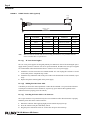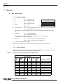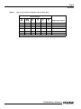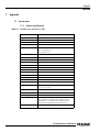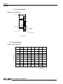
1
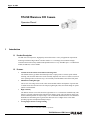
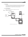
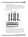
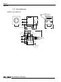
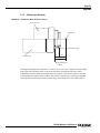
TM-250 Miniature CCD Camera
Operation Manual
69-0081
Rev. A
Imaging Products
Notice
The material contained in this manual consists of information that is proprietary to PULNiX America, Inc., and may only be
used by the purchasers of the product. PULNiX America, Inc. makes no warranty for the use of its product and assumes no
responsibility for any errors which may appear or for damages resulting from the use of the information contained herein.
PULNiX America, Inc. reserves the right to make changes without notice.
Microsoft, Windows 98, Windows 95, Windows NT, and Windows Explorer are either registered trademarks or trademarks of
Microsoft Corporation in the United States and/or other countries.
Warranty
All of our solid-state cameras have a full three-year warranty. If any such product proves defective during this warranty period,
PULNiX America, Inc. will repair the defective product without charge for parts and labor or will provide a replacement in
exchange for the defective product. This warranty shall not apply to any damage, defect or failure caused by improper use or
inadequate maintenance.
Certifications
CE Compliance
The TM-250 camera has been certified to conform to the requirements of Council Directive 89/336/EC for electromagnetic
compatibility and to comply with the following European Standards:
Immunity:
Emissions:
EN50082-2/1995
EN55011/EN61326-1, Class A
All PULNiX products bearing the CE mark have been declared to be in conformance with the applicable EEC Council Directives. However, certain factory-installed options or customer-requested modifications may compromise electromagnetic compatibility and affect CE compliance. Please note that the use of interconnect cables that are not properly grounded and shielded
may affect CE compliance.
Contact PULNiX Applications Engineering Department for further information regarding CE compliance.
FCC
This equipment has been tested and found to comply with the limits for a Class A digital device, pursuant to Part 15 of the
FCC Rules. These limits are designed to provide reasonable protection against harmful interference when the equipment is
operated in a commercial environment. This equipment generates, uses and can radiate radio frequency energy and, if not
installed and used in accordance with the instruction manual, may cause harmful interference to radio communications. Operation of this equipment in a residential area may cause harmful interference, in which case the user will be required to correct
the interference at his own expense.
WARNING
A
SS
O C I AT I O
N
®
RM
UL
FI
S
I
MEMBER
REG
TED IMA
MA
O
G
IN
G
TM-250 Operation Manual
PULNiX America, Inc.
1330 Orleans Drive
Sunnyvale, CA 94089
Tel:(408) 747-0300
Tel:(800) 445-5444
Fax:(408) 747-0880
E-mail: [email protected]
www.pulnix.com
AU
T
Changes or modifications to this unit not expressly approved by the party responsible for
FCC compliance could void the user’s authority to operate the equipment.
TE ED
R
PULNiX AMERICA, INC.
REGISTERED TO ISO-9001
FILE #A3942
TM-250 Miniature CCD Camera
i
Table of Contents
1 Introduction . . . . . . . . . . . . . . . . . . . . . . . . . . . . . 1
1.1
1.2
1.3
1.4
1.5
Product Description. .
Features . . . . . . . . . .
Functional Options . .
Applications . . . . . . .
System Configuration.
.
.
.
.
.
.
.
.
.
.
.
.
.
.
.
.
.
.
.
.
.
.
.
.
.
.
.
.
.
.
.
.
.
.
.
.
.
.
.
.
.
.
.
.
.
.
.
.
.
.
.
.
.
.
.
.
.
.
.
.
.
.
.
.
.
.
.
.
.
.
.
.
.
.
.
.
.
.
.
.
.
.
.
.
.
.
.
.
.
.
.
.
.
.
.
.
.
.
.
.
.
.
.
.
.
.
.
.
.
.
.
.
.
.
.
.
.
.
.
.
.1
.1
.2
.3
.3
2 Installation . . . . . . . . . . . . . . . . . . . . . . . . . . . . . . 4
2.1
Getting Started. . . . . . . . . . . . . . . . . . . . . . . . . . . . . . 4
2.1.1
2.1.2
2.1.3
2.2
Unpacking Instructions . . . . . . . . . . . . . . . . . . . . . . . . . . . . . . . . . . . . 4
Components List. . . . . . . . . . . . . . . . . . . . . . . . . . . . . . . . . . . . . . . . . 4
Accessories . . . . . . . . . . . . . . . . . . . . . . . . . . . . . . . . . . . . . . . . . . . . . 4
Camera Setup . . . . . . . . . . . . . . . . . . . . . . . . . . . . . . . 4
2.2.1
2.2.2
2.2.3
2.2.4
2.2.5
2.2.6
Connector Pin Configurations . . . . . . . . . . . . . . . . . . . . . . . . . . . . . . 4
Power Supply and Power Cable . . . . . . . . . . . . . . . . . . . . . . . . . . . . . 5
Attaching the Video Output . . . . . . . . . . . . . . . . . . . . . . . . . . . . . . . . 7
Attaching the Camera Lens . . . . . . . . . . . . . . . . . . . . . . . . . . . . . . . . 7
Auto-Iris Lens Setup . . . . . . . . . . . . . . . . . . . . . . . . . . . . . . . . . . . . . . 7
Monitor Display Mode . . . . . . . . . . . . . . . . . . . . . . . . . . . . . . . . . . . . 7
3 Operation . . . . . . . . . . . . . . . . . . . . . . . . . . . . . . . 8
3.1
Rear Panel Switches. . . . . . . . . . . . . . . . . . . . . . . . . . . 8
3.1.1
3.1.2
3.1.3
3.2
External Sync . . . . . . . . . . . . . . . . . . . . . . . . . . . . . . 12
3.2.1
3.2.2
3.3
Function Control . . . . . . . . . . . . . . . . . . . . . . . . . . . . . . . . . . . . . . . . 8
Shutter Control . . . . . . . . . . . . . . . . . . . . . . . . . . . . . . . . . . . . . . . . . 8
Field and Frame Modes. . . . . . . . . . . . . . . . . . . . . . . . . . . . . . . . . . . 11
Timing . . . . . . . . . . . . . . . . . . . . . . . . . . . . . . . . . . . . . . . . . . . . . . . . 13
Interfacing to Frame Grabbers . . . . . . . . . . . . . . . . . . . . . . . . . . . . . 13
Operating Modes . . . . . . . . . . . . . . . . . . . . . . . . . . . . 13
3.3.1
3.3.2
3.3.3
3.3.4
3.3.5
3.3.6
3.3.7
3.3.8
Standard Interlace Mode. . . . . . . . . . . . . . . . . . . . . . . . . . . . . . . . . . 14
Cyclic (Continuous) Shutter Mode . . . . . . . . . . . . . . . . . . . . . . . . . 14
Asynchronous Reset and Asynchronous Shutter . . . . . . . . . . . . . . . 14
External Sync Mode . . . . . . . . . . . . . . . . . . . . . . . . . . . . . . . . . . . . . 15
Reset-Restart Mode . . . . . . . . . . . . . . . . . . . . . . . . . . . . . . . . . . . . . 15
External Shutter Control . . . . . . . . . . . . . . . . . . . . . . . . . . . . . . . . . 15
Integration. . . . . . . . . . . . . . . . . . . . . . . . . . . . . . . . . . . . . . . . . . . . . 15
Non-Interlace Operation . . . . . . . . . . . . . . . . . . . . . . . . . . . . . . . . . 15
4 TM-250 External Signals . . . . . . . . . . . . . . . . . . . . 16
4.1
4.2
4.3
External VD . . . . . . . . . . . . . . . . . . . . . . . . . . . . . . . 16
External HD and Internal Sampling Clock . . . . . . . . . . . 16
Width Mode Reset-Restart Operation . . . . . . . . . . . . . 17
5 Operation Mode . . . . . . . . . . . . . . . . . . . . . . . . . . 18
5.1
Cyclic Mode . . . . . . . . . . . . . . . . . . . . . . . . . . . . . . . 18
5.1.1
5.1.2
5.1.3
5.1.4
5.2
No Discharge Operation . . . . . . . . . . . . . . . . . . . . . . . . . . . . . . . . . 18
Fast Shutter Cyclic Mode . . . . . . . . . . . . . . . . . . . . . . . . . . . . . . . . . 19
Trigger Position Reset/Restart Shutter Mode . . . . . . . . . . . . . . . . . 20
Trigger Width Reset/Restart Mode . . . . . . . . . . . . . . . . . . . . . . . . . 21
Asynchronous Operation. . . . . . . . . . . . . . . . . . . . . . . 22
TM-250 Miniature CCD Camera
ii
Table of Contents
5.2.1
5.2.2
5.2.3
5.2.4
5.2.5
5.2.6
TM-250 Strobe Asynchronous Shutter Mode . . . . . . . . . . . . . . . . . 22
Post-Reset Asynchronous Shutter Mode . . . . . . . . . . . . . . . . . . . . . 23
Pulse Width Asynchronous Shutter Mode . . . . . . . . . . . . . . . . . . . . 25
Pre-Reset Asynchronous Shutter Mode. . . . . . . . . . . . . . . . . . . . . . 25
Double Pulse Integration Mode . . . . . . . . . . . . . . . . . . . . . . . . . . . . 27
Pulse Width Integration Mode . . . . . . . . . . . . . . . . . . . . . . . . . . . . . 27
6 Troubleshooting . . . . . . . . . . . . . . . . . . . . . . . . . . 29
6.1
Problems and Solutions . . . . . . . . . . . . . . . . . . . . . . . 29
6.1.1
6.1.2
6.1.3
6.1.4
6.2
Symptom: No Video . . . . . . . . . . . . . . . . . . . . . . . . . . . . . . . . . . . . . 29
Symptom: Dark Video . . . . . . . . . . . . . . . . . . . . . . . . . . . . . . . . . . . . 29
Symptom: Non-Synchronized Video . . . . . . . . . . . . . . . . . . . . . . . . . 29
Symptom: Flickering Video in Reset/Restart Mode . . . . . . . . . . . . . 29
Information and Support Resources . . . . . . . . . . . . . . 30
7 Appendix . . . . . . . . . . . . . . . . . . . . . . . . . . . . . . . 31
7.1
Specifications . . . . . . . . . . . . . . . . . . . . . . . . . . . . . . 31
7.1.1
7.1.2
7.1.3
7.1.4
7.2
Product Specifications . . . . . . . . . . . . . . . . . . . . . . . . . . . . . . . . . . . 31
Physical Dimensions . . . . . . . . . . . . . . . . . . . . . . . . . . . . . . . . . . . . . 32
C-Mount Specifications . . . . . . . . . . . . . . . . . . . . . . . . . . . . . . . . . . 33
Front End Detail . . . . . . . . . . . . . . . . . . . . . . . . . . . . . . . . . . . . . . . . 34
Spectral Response . . . . . . . . . . . . . . . . . . . . . . . . . . . 34
TM-250 Miniature CCD Camera
iii
List of Figures
FIGURE 1.
TM-250 System Configuration . . . . . . . . . . . . . . . . . . . . . . . . . . . . 3
FIGURE 2.
12P-02S Interface Cable (optional). . . . . . . . . . . . . . . . . . . . . . . . . 6
FIGURE 3.
Input Signals . . . . . . . . . . . . . . . . . . . . . . . . . . . . . . . . . . . . . . . . . . 12
FIGURE 4.
TM-250 Timing Chart . . . . . . . . . . . . . . . . . . . . . . . . . . . . . . . . . . 13
FIGURE 5.
External VD . . . . . . . . . . . . . . . . . . . . . . . . . . . . . . . . . . . . . . . . . . 16
FIGURE 6.
Proper Operation . . . . . . . . . . . . . . . . . . . . . . . . . . . . . . . . . . . . . 16
FIGURE 7.
Proper Operation . . . . . . . . . . . . . . . . . . . . . . . . . . . . . . . . . . . . . 17
FIGURE 8.
Illegal Operation . . . . . . . . . . . . . . . . . . . . . . . . . . . . . . . . . . . . . . 17
FIGURE 9.
No Discharge Operation (Frame Accumulation Mode). . . . . . . . 19
FIGURE 10.
No Discharge Operation (Field Accumulation Mode) . . . . . . . . . 19
FIGURE 11.
High-Speed Cyclic Shutter Mode Timing . . . . . . . . . . . . . . . . . . . 20
FIGURE 12.
Trigger Position Reset/Restart Mode Timing . . . . . . . . . . . . . . . . 21
FIGURE 13.
Trigger Width Reset/Restart Shutter Mode Timing . . . . . . . . . . . 22
FIGURE 14.
Strobe Asynchronous Shutter Mode Timing. . . . . . . . . . . . . . . . . 23
FIGURE 15.
Post-Reset Asynchronous Shutter Mode Timing . . . . . . . . . . . . . 24
FIGURE 16.
Pulse Width Asynchronous Shutter Mode . . . . . . . . . . . . . . . . . . 25
FIGURE 17.
Pre-Reset Asynchronous Shutter Mode . . . . . . . . . . . . . . . . . . . . 26
FIGURE 18.
Double Pulse Integration Mode . . . . . . . . . . . . . . . . . . . . . . . . . . 27
FIGURE 19.
Pulse Width Integration Mode . . . . . . . . . . . . . . . . . . . . . . . . . . . 28
FIGURE 20.
Physical Dimensions . . . . . . . . . . . . . . . . . . . . . . . . . . . . . . . . . . . 32
FIGURE 21.
Combination With “CS-Mount” Camera . . . . . . . . . . . . . . . . . . . 33
FIGURE 22.
Front End Detail . . . . . . . . . . . . . . . . . . . . . . . . . . . . . . . . . . . . . . 34
FIGURE 23.
Spectral Response . . . . . . . . . . . . . . . . . . . . . . . . . . . . . . . . . . . . . 34
TM-250 Miniature CCD Camera
iv
List of Tables
TABLE 1.
12-Pin Connector Configuration . . . . . . . . . . . . . . . . . . . . . . . . . . . . . . . . . .5
TABLE 2.
Shutter Speed Control in High-Speed Cyclic Shutter Mode . . . . . . . . . . . . .8
TABLE 3.
Shutter Speed Control in Post-Reset Asynchronous Shutter Mode . . . . . .10
TABLE 4.
Shutter Speed Control in Pre-Reset Asynchronous Shutter Mode . . . . . . .10
TABLE 5.
Shutter Speed Control in High-Speed Cyclic Shutter Mode . . . . . . . . . . . .18
TABLE 6.
Trigger Position Reset/Restart Shutter Mode . . . . . . . . . . . . . . . . . . . . . . .21
TABLE 7.
Trigger Width Reset/Restart Shutter Mode . . . . . . . . . . . . . . . . . . . . . . . . .22
TABLE 8.
Strobe Asynchronous Shutter Mode . . . . . . . . . . . . . . . . . . . . . . . . . . . . . .22
TABLE 9.
Shutter Speed Control in Post-Reset Asynchronous Shutter Mode . . . . . .24
TABLE 10.
Pulse Width Asynchronous Shutter Mode . . . . . . . . . . . . . . . . . . . . . . . . . .25
TABLE 11.
Shutter Speed Control in Pre-Reset Asynchronous Shutter Mode . . . . . . .26
TABLE 12.
Double Pulse Integration Mode . . . . . . . . . . . . . . . . . . . . . . . . . . . . . . . . . .27
TABLE 13.
Pulse Width Integration Mode . . . . . . . . . . . . . . . . . . . . . . . . . . . . . . . . . . .28
TABLE 14.
TM-250 Product Specifications Table . . . . . . . . . . . . . . . . . . . . . . . . . . . . . .31
TM-250 Miniature CCD Camera
August 30, 2001
TM-250 Miniature CCD Camera
Operation Manual
1
Introduction
1.1 Product Description
The TM-250 is an inexpensive, high-quality camera that meets a variety of application requirements.
Featuring an advanced Hyper-HAD1 interline transfer 1/2" CCD imager, this miniaturized highresolution camera offers many standard and optional features at a very affordable price. A CCIR-format
model, the TM-260, is also available.
1.2 Features
•
Variable electronic shutter and random CCD integration
The substrate drain-type shutter mechanism provides a superb picture at various speeds without
smearing. The electronic shutter rate can be externally adjusted, from 1/60 to 1/10,000 (1/29,100 in
some operating modes) in discrete steps, via a manually controlled DIP switch on the back panel.
•
Miniaturized and lightweight
The use of a CCD image sensor in the video camera module and the development of special mini
C-mount lenses allow the TM-250 to be compact, lightweight, robust, and small enough to operate
just like a remoted head.
•
High sensitivity
The TM-250 camera is one of the most low-light sensitive 1/2" CCD cameras available today. This
feature is especially important when using the faster shutter speeds. The CCD detects images into
the near-infrared spectrum. It requires only 1.0 lux of minimum illumination and 0.5 lux minimum
illumination at maximum gain. In general, this allows the use of a higher lens F-value while
providing a greater field depth and sharper images.
•
Low lag/high resistance to image burning
1. Hyper-HAD is a trademark of SONY Corporation.
TM-250 Miniature CCD Camera
Page 2
Introduction
Because the CCD is highly resistant to image burning, the camera may be exposed to bright objects
for a long period of time. Because a “smear” phenomenon may occur when shooting a very bright
object, we recommend an infrared cutoff filter to obtain a clear picture (optional).
•
AGC/MGC selection, manual gain control and gamma adjustment
These adjustments, which are particularly important in vision system applications, are externally
adjustable via switches on the rear plate.
•
Genlock circuit
A genlock circuit is built in to accept external sync for applications in which external sync is
required.
•
High resistance to magnetic field and vibration/mechanical shock
The CCD imager’s rugged design allows it to withstand strong vibration and shock with little or no
noise appearing in the picture. Since the TM-250 is not influenced by a magnetic field, it will
produce stable images even when placed next to objects such as electric furnaces, welding
machines or NMR scanners.
•
Quick start-up and low power consumption
Image capture can begin within a second after turning on the camera. The power consumption is
only 2.5W. This makes the camera excellent for use with battery-operated systems.
•
Camera-mounting flexibility
The TM-250 has tapped holes on all four sides to allow a tripod mount to be installed from any
angle.
•
Three-year warranty
The CCD solid-state image sensor allows the camera to maintain a superior performance level
indefinitely while requiring virtually no maintenance. PULNiX backs all of the TM series cameras
with a three-year warranty.
Warning:
Unscrewing the camera cover or opening the camera in any way
will void this warranty unless prior written approval is
obtained from the factory.
1.3 Functional Options
•
Adjustable backfocus front end
•
Internal IR Cut Filter (OP3-1)
•
Optical Filter Removal (OP3-2)
•
Glassless CCD Imager (OP21)
•
Low impedance (75Ω) termination
•
NIR CCD
•
SONY pinouts
TM-250 Miniature CCD Camera
Page 3
Introduction
1.4 Applications
The miniature size of the TM-250 camera eliminates the need for a remoted imager camera in all but the
most confined spaces. This camera fits easily, both physically and functionally, into all types of machine
vision, automated inspection, and related applications. Other uses include remotely piloted vehicles,
miniature inspection devices, surveillance, microscopes, and medical equipment.
1.5 System Configuration
Figure 1 (below) presents a typical system configuration for the TM-250.
FIGURE 1.
TM-250 System Configuration
SECURE HATCH IN
PLACE AFTER FINAL
ADJUSTMENTS.
Computer with
Frame Grabber
Board
0
OFF 1.0 FRM 0
0
OFF MGC CYC 0
Power
Ext. Sync
Trigger
VIdeo Output*
GAIN
POWER
VIDEO
* Video Output is the same as BNC connector
Monitor
TM-250 Miniature CCD Camera
Page 4
Installation
2
Installation
The following instructions are provided to help you to set up your video camera system quickly and
easily. We suggest that you read through these instructions before unpacking and setting up your camera
system.
2.1 Getting Started
2.1.1 Unpacking Instructions
We recommend that you save the original packing cartons for the cameras and lenses in case you need to
return or exchange an item.
We also recommend that you bench-test any equipment being sent to another location for field
installation to assure that everything is fully operational as a system.
2.1.2 Components List
Please begin by checking your order against the Components List (below) to assure that you have
received everything as ordered, and that nothing has been overlooked in the packing materials. If any
item is missing, please contact your PULNiX representative immediately.
•
TM-250 camera
•
TM-250/260 data sheet
•
TM-250 operation manual (if ordered)
2.1.3 Accessories
Following is a list of additional accessories or equipment that may be recommended or required for your
particular application. Please check with your PULNiX representative before installing your video
system to determine what you might need.
•
Power Cable: 12P-02S Interface Cable
•
Power Supply: PD-12U series, and K series.
2.2 Camera Setup
2.2.1 Connector Pin Configurations
The TM-250 has a 12-pin connector for power input. In general, Pin #1 is
Ground and Pin #2 is +12V DC. The other pins handle a number of other input
and output functions, as shown in the table below.
9
1
2
3
10
11
12
4
7
6
5
TM-250 Miniature CCD Camera
8
Page 5
Installation
TABLE 1.
12-Pin Connector Configuration
Pin
Description
Pin
Description
1
GND
7
VD Input
2
+12V DC
8
GND
3
GND
9
HD Input
4
Video Out
10
N/C
5
GND
11
N/C
6
VINIT/TRIG Input
12
GND
2.2.2 Power Supply and Power Cable
2.2.2 (a)
Power Supplies
PULNiX recommends the following power supplies:
K25-12V
110V AC/12V DC
2.1A power supply (OEM type)
K50-12V
110V AC/12V DC
4.2A power supply (OEM type)
PD-12UU
100-240V AC/12V DC
1.2A universal voltage power supply
PD-12UP
PD-12UU with12-pin connector
US plug
PD-12UE
PD-12UU
European plug
PD-12UEP
PD-12UU with 12-pin connector
European plug
If you are providing power through the 12-pin connector, the PD-12UUP power supply is available with
the 12-pin mating connector already attached to the leads from the power supply. The PD-12UU power
supply can be connected to the PULNiX power cable via a terminal strip or directly.
When wiring the PD-12 power supply directly, please note the following:
•
The lead ends must be twisted together and tin soldered for strength and electrical continuity.
•
Shrink tubing or a similar insulator should be used to prevent exposed leads from touching.
•
The +12V lead is marked with a red stripe or white lettering; be sure not to reverse the leads.
•
All connections must be properly insulated to prevent shorting.
2.2.2 (b)
PULNiX Power Cables
If you are using PULNiX power cables, such as the 12P-02S, please refer to the appropriate pin-out
diagram. The color coded leads use Gray for Ground and Yellow for +12V DC.
TM-250 Miniature CCD Camera
Page 6
Installation
FIGURE 2.
12P-02S Interface Cable (optional)
Flying
Leads
1
32mm
2,000mm± 10mm
(2 Meters)
1 PC-12P (Hirose Part #10A-10P-12S/PC12P)
12P-02S Interface Cable
Note:
Pin#
Lead Color
Function
Pin#
Lead Color
Function
1
Gray
GND
7
Black coax
VD Input
2
Yellow
+12V DC
8
White coax shield
GND
3
Red coax shield
GND
9
White coax
HD Input
4
Red coax
Video
10
Brown
N/C
5
Orange coax shield
GND
11
Blue
N/C
6
Orange coax
VINIT/TRIG
12
Black coax shield
GND
Make sure that the unused leads are not touching and that there is no possibility that the
leads could short due to exposed wires.
2.2.2 (c)
“K” Series Power Supplies
The “K” series power supplies are designed primarily for OEM users who will be mounting the power
supply inside a protective enclosure. For use in exposed situations, the PD-12UU series power supplies
are recommended. Follow the directions below to connect a “K” series power supply.
1.
2.
3.
Attach the 110V line cord to the two terminals marked “AC.” Do not plug the cord into a 110V AC
socket until you have completed steps 2 and 3.
Attach the Gray and Yellow leads of the power cable to the Ground and 12V DC terminals, respectively.
Replace the plastic terminal guard on the power supply.
2.2.2 (d)
Building Your Own Power Cable
Consult the pin-out for the camera purchased. Connect the Ground and +12V power leads of the PD12UUP power connector to Pin #1 and Pin #2, respectively (power must be DC regulated, and of
sufficient current to properly power the camera).
2.2.2 (e)
Attaching the Power Cable to the Connector
The 12-pin connector is keyed and will only fit in one orientation. Follow these directions to properly
attach the power cable to the camera connector:
1.
2.
3.
Rotate the connector while applying slight pressure until the keyways line up.
Press the connector into place until firmly seated.
Plug the power cord into the 100V AC socket. This will power the camera up.
TM-250 Miniature CCD Camera
Page 7
Installation
2.2.3 Attaching the Video Output
Most users utilize the BNC connector for video output from the camera. Connect the output from the
camera to the input of your monitor, VCR, or switching device. The input of the monitor should be
balanced for 75Ω termination. Standard RG-59 type coaxial cable should carry a full video signal for up
to 500 feet.
To output the video and input the power and sync to a camera over a single cable, use the PULNiX
multi-conductor cables, such as the 12P-02S, etc. The mini coaxial leads in PULNiX multi-conductor
cables are designed for short runs of no longer than 100 feet.
Note:
Make sure that no extraneous wires are visible which could cause a short.
2.2.4 Attaching the Camera Lens
The TM-250 camera accepts 1/2" or larger format size C-mount lenses. To attach the C-mount lens to
the camera, carefully engage the threads and rotate the lens clockwise until it firmly seats on the
mounting ring. Do not force the lens if it does not seat properly. Please note that some lenses with
extremely long flangebacks may exceed the mounting depth of the camera.
2.2.5 Auto-Iris Lens Setup
Auto-iris lenses with full video input can be used with the PULNiX TM-250, although this camera
model does not come equipped with auto-iris output.
Note:
Make sure that the power is removed from the camera before connecting or disconnecting
the auto-iris lens. There is a small chance that the auto-iris lens could be damaged by
plugging or unplugging it while the camera is powered up.
Power down the camera before installing the auto-iris lens. To install the auto-iris lens in a PULNiX
camera without an auto-iris output, wire the signal (video) on the lens into the terminal 1 Vp-p video
output on the camera.
Point the camera at a light area and then quickly towards a darker area. If everything is working
properly, the iris should adjust for the light change.
2.2.6 Monitor Display Mode
For monitoring real-time video, connect the video output to a video monitor or other device.
TM-250 Miniature CCD Camera
Page 8
Operation
3
Operation
3.1 Rear Panel Switches
3.1.1 Function Control
1.
2.
3.
4.
5.
6.
7.
F2:
Up = Function 2 ON
UP
.45
FLD
S3
S1
F2
Down = Function 2 OFF
S2
F1
S0
AGC
ASY
F1:
Up = Function 1 ON
Down = Function 1 OFF
0
0
OFF
1.0
FRM
Gamma:
Up = 0.45
0
0
MGC
CYC
OFF
DOWN
Down = 1.0
AGC/MGC switch: Up
=AGC (Automatic Gain Control)
Down =MGC (Manual Gain Control)*
* When MGC is selected, the camera gain can be adjusted using the potentiometer on the back
plate.
FLD/FRM:
Up = FLD (Field Mode)
Down = FRM (Frame Mode)
* Select FRM for strobe applications and FLD for high shutter speed applications.
See Section 3.1.3 on page 11 for details.
ASY/CYC:
Up
= Asynchronous mode (randomly resettable)
Down = Cyclic mode Shutter (free-running only)
S3 to S0: See Section 3.1.2 on page 8.
Note: Functions of the F1 and F2 switches vary depending on the operating mode selected.
3.1.2 Shutter Control
Shutter speeds on the TM-250 can be controlled using DIP switches S3, S2, S1, and S0. The following
tables show the various switch settings in different operating modes.
TABLE 2.
Shutter Speed Control in High-Speed Cyclic Shutter Mode
Switch Position
F1
OFF
ASY
CYC
S3
0
S2
0
S1
0
S0
0
Shutter Speed (Sec.)
Down
Down
Down
Down
Down
Down
1/30 (no shutter)
Down
Down
Down
Down
Down
Up
1/60
Down
Down
Down
Down
Up
Down
1/100
Down
Down
Down
Down
Up
Up
1/120
Down
Down
Down
Up
Down
Down
1/250
Down
Down
Down
Up
Down
Up
1/500
Down
Down
Down
Up
Up
Down
1/1,000
Down
Down
Down
Up
Up
Up
1/5,000
Down
Down
Up
Down
Down
Down
1/2,100
TM-250 Miniature CCD Camera
Page 9
Operation
TABLE 2.
Shutter Speed Control in High-Speed Cyclic Shutter Mode
Switch Position
F1
OFF
ASY
CYC
S3
0
S2
0
S1
0
S0
0
Shutter Speed (Sec.)
Down
Down
Up
Down
Down
Down
Up
Down
Down
Up
1/2,800
Up
Down
1/3,500
Down
Down
Up
Down
Up
Up
1/4,400
Down
Down
Up
Up
Down
Down
1/6,200
Down
Down
Down
Up
Up
Down
Up
1/10,200
Down
Up
Up
Up
Down
1/29,100
F2: not applicable
TM-250 Miniature CCD Camera
Page 10
Operation
TABLE 3.
Shutter Speed Control in Post-Reset Asynchronous Shutter Mode
Switch Position
F1
OFF
ASY
CYC
S3
0
S2
0
S1
0
S0
0
Shutter Speed (Sec.)
Down
Up
Down
Down
Down
Up
1/60
Down
Up
Down
Down
Up
Down
1/120
Down
Up
Down
Down
Up
Up
1/250
Down
Up
Down
Up
Down
Down
1/500
Down
Up
Down
Up
Down
Up
1/1,000
Down
Up
Down
Up
Up
Down
1/1,600
Down
Up
Down
Up
Up
Up
1/1,800
Down
Up
Up
Down
Down
Down
1/2,100
Down
Up
Up
Down
Down
Up
1/2,400
Down
Up
Up
Down
Up
Down
1/2,800
Down
Up
Up
Down
Up
Up
1/3,500
Down
Up
Up
Up
Down
Down
1/4,400
Down
Up
Up
Up
Down
Up
1/6,200
Down
Up
Up
Up
Up
Down
1/10,200
F2 Up: SYNC signal is continuous.
F2 Down: SYNC signal is available in one field right after VINIT.
TABLE 4.
Shutter Speed Control in Pre-Reset Asynchronous Shutter Mode
Switch Position
F1
OFF
ASY
CYC
S3
0
S2
0
S1
0
S0
0
Shutter Speed (Sec.)
Up
Up
Down
Down
Down
Up
1/29,100
Up
Up
Down
Down
Up
Down
1/10,200
Up
Up
Down
Down
Up
Up
1/6,200
Up
Up
Down
Up
Down
Down
1/4,400
Up
Up
Down
Up
Down
Up
1/3,500
Up
Up
Down
Up
Up
Down
1/2,800
Up
Up
Down
Up
Up
Up
1/2,400
Up
Up
Up
Down
Down
Down
1/2,100
Up
Up
Up
Down
Down
Up
1/1,800
Up
Up
Up
Down
Up
Down
1/1,600
Up
Up
Up
Down
Up
Up
1/1,500
F2 Up: SYNC signal is continuous.
F2 Down: SYNC signal is available in one field right after VINIT.
TM-250 Miniature CCD Camera
Page 11
Operation
3.1.3 Field and Frame Modes
The standard factory setting for the TM-250 camera is FRAME MODE. The field and frame integration
mode is selectable using the switch on the rear panel of the camera. The frame integration is used to
separate all CCD pixels. The exposure of Odd and Even fields generates the full frame image shown in
the figure below.
1
2
3
261 262
263
264 524
525
1
2
3
261 262
263
264 524
525
1
2
3
261
262
263
264 524
525
HD
VD
Odd
Field
Even
Field
Odd
Field
Even
Field
Odd
Field
Odd
Even
Odd
Even
Odd
Even
Odd
Even
Odd
Even
Odd
Even
Even
Field
Frame Integration
Field Integration
3.1.3 (a)
Field Mode
In Field mode, two horizontal rows are scanned (binned) simultaneously. At each interlace scan, the
scanned pairs are changed. Thus the sensitivity of the CCD is doubled for one field of integration. When
compared to Frame mode, in which each horizontal row is scanned simultaneously, the CCD obtains the
same sensitivity in half the time period. This mode is useful when Shutter is used. The field integration
is done by combining two pixel rows (binning) together and each pair alternates as interlace scan is
generated. Row 1 is binned with row 2, and row 3 is binned with row 4. In Field 2, row 2 is binned with
row 3, row 4 with row 5, and so on. The field mode is very effective in shutter mode since the pixel
sensitivity is doubled for field integration (1/60 sec) and equals with frame mode (one row at 1/30 sec).
Since shutter mode is only one field output per shutter and darker than normal image, two-row binning
is effective. This mode also reduces interlace moire when a sharp horizontal pattern is observed. For
higher pixel definition such as gauging and sub-pixel interpolation, Frame mode operation is
recommended.
Moire is unnoticeable because of alternating two-row scanning. The vertical resolution in Field mode is
not as good as that in Frame mode, but it is sufficient to view the full vertical resolution of the TV
format.
3.1.3 (b)
Frame Mode
In Frame mode, each horizontal row is scanned as interlace scanning. The integration of each pixel is
one frame period. In Frame mode, vertical pixel resolution is good, and the exact location is obtained. In
comparison with Field mode, however, Frame mode has the disadvantage of showing vertical Moire.
Frame mode should be used in applications that need strobe lighting, because full frame resolution is
achieved in this mode. For higher pixel definition such as gauging and sub-pixel interpolation, Frame
mode operation is recommended.
TM-250 Miniature CCD Camera
Page 12
Operation
3.2 External Sync
The TM-250 can accept external sync from an external sync generator or frame grabber. Its input
specifications are:
Internal/External auto switch
fH=15.734 KHz ±5%, fV=59.95 Hz ±5%
Note:
FIGURE 3.
The TM-250 has a one (1) horizontal line delay between the input VD signal and the
output video. If external vertical drive (VD) is applied to the camera, it may cause the
video output to be delayed 1 HD (1 HD = ~64.0 µs). If the imaging system is capable of
automatically detecting the start of video (within a few HD), then no problem will exist. If
it is not capable of automatically detecting the start of video, you may need to reconfigure
the video capturing sequence to delay video acquisition of 1HD.
Input Signals
1/f(horizontal)
+5Volts HD
TTL Level
0 Volts
3 - 5µsec
1/60
+5Volts VD
TTL Level
0 Volts
1 to 9HD
TM-250 Miniature CCD Camera
Page 13
Operation
3.2.1 Timing
FIGURE 4.
TM-250 Timing Chart
HD
6.36µSec
819
91
768
B40
B1
40
757
758
759
760
761
762
763
764
765
766
767
768
3
B1
B2
B3
1
2
3
4
5
6
7
8
9
10
D1
22
D22
77
B40
B1
40
CCD photo sensors
allocation
Optical
black period
H register
stop period
Optical
black period
Image sensing period
Dummy
H register
CCD output
signal
Effective picture
period
154
H BLK 10.76µSec
CBRK
Composite video
output
21
1.47µSec
70
H SYNC
4.89µSec
63.56µSec
910
(1 horizontal line)
3.2.2 Interfacing to Frame Grabbers
The TM-250 camera can be connected to a frame grabber using either the 12-pin connector or the BNC
connector on the rear panel of the camera.
3.3 Operating Modes
Besides normal operation, the TM-250 supports the following versatile operations that can be selected
by the DIP switch on the rear panel of the camera:
•
Standard Interlace Mode
Field integration Mode
Frame Integration Mode
•
External Sync Mode
•
Non-interlace Mode
•
Cyclic (Continuous) Shutter Mode
•
Asynchronous Reset and Asynchronous Shutter
TM-250 Miniature CCD Camera
Page 14
Operation
•
Reset-Restart Mode
Frame Integration Mode
Field Integration Mode
•
Reset-Restart Mode with Electronic Shutter
Frame Integration Mode
Field Integration Mode
•
Integration Mode (Strobe application)
3.3.1 Standard Interlace Mode
3.3.1 (a)
Field Mode and Frame Mode
The field and frame integration mode is selectable. The frame integration is used to separate all CCD
pixels and the exposure of Odd and Even fields generate the full frame image shown in the figure below.
3.3.1 (b)
Field Mode Binning
The field integration is done by combining two pixel rows (binning) together, each pair alternating as
interlace scan is generated. Row 1 is binned with row 2, and row 3 is binned with row 4. In Field 2, row
2 is binned with row 3, row 4 with row 5, and so on. Field mode is very effective in shutter mode
because the pixel sensitivity is doubled for field integration (1/60 sec) and equals frame mode (one row
at 1/30 sec). Because Shutter mode is only one field output per shutter and darker than normal image,
two-row binning is effective. This mode also reduces interlace moire when a sharp horizontal pattern is
observed. For higher pixel definition such as gauging and sub-pixel interpolation, Frame mode
operation is recommended.
3.3.2 Cyclic (Continuous) Shutter Mode
With back-plate shutter control, the TM-250 operates at the internally predefined shutter speeds. Each
field output is exposed for the same period. The shutter control varies the substrate discharge timing.
The duration between the shutter pulse and transfer gate timing (11H from VD edge) decides the
exposure time (16H for CCIR). The following three cyclic shutter modes are available:
•
High-Speed Cyclic Shutter mode
•
Trigger Position Reset/Restart Shutter mode
•
Trigger Width Reset/Restart Shutter mode
Contact PULNiX for timing charts of various cyclic shutter modes.
3.3.3 Asynchronous Reset and Asynchronous Shutter
By supplying VINIT pulse on pin #6, the camera can be reset asynchronously. In this mode, when
VINIT is kept high, it continuously discharges the CCD and outputs the field video signal upon the
negative going edge. The output stays continuous during VINIT low. The first field output is always
Odd.
TM-250 Miniature CCD Camera
Page 15
Operation
The following four asynchronous shutter modes are available:
•
Strobe Asynchronous Shutter Mode
•
Pre-Reset Asynchronous Shutter Mode
•
Post-Reset Asynchronous Shutter Mode
•
Pulse Width Asynchronous Shutter Mode
Please contact PULNiX for timing charts of various asynchronous shutter modes.
3.3.4 External Sync Mode
TM-250 accepts standard RS-170 external sync, which is defined as horizontal sync (HD) and vertical
sync (VD). The phase-locked loop jitter is designed to be the minimum (< 5ns) in this category using
the latest PLL chip. The wide capture range enables the camera to operate at an extended temperature
range (optional) of -35°C to 65°C. HD and VD input is TTL level and the high impedance is 100KΩ or
75Ω (optional).
3.3.5 Reset-Restart Mode
Rather than using VINIT as asynchronous reset, the camera can be reset using EXT VD. In this mode,
the camera needs multiple VD pulses to output valid images, depending on whether it is set to Field or
Frame mode. Usually, the first field (Field mode) or the first frame (Frame mode) are garbage because
of previous signal residuals prior to reset. A frame grabber has to know which frame or field to capture.
External HD must be applied for this operation.
3.3.6 External Shutter Control
The shutter speed or exposure can be controlled with external pulse (TRIG) in this mode. In
combination with Reset-Restart Pulse (EXT VD), the camera can be externally controlled for imagecapture timing as well as for exposure time.
This is an excellent application for capturing multiple images (two fields of images) of indexing objects
under various lighting or brightness conditions. When Frame mode is selected, the full vertical
resolution is achieved by taking two fields of shutter images, whether or not you are using an electronic
shutter.
3.3.7 Integration
When integration control (VINIT) is low, the CCD imager keeps integrating. When the signal returns to
high, it enables the charge transfer for video output. This mode integrates longer than one field. With
strobe light application, it can capture randomly strobed images during the integration. It also increases
the exposure time to enhance low-light viewing.
3.3.8 Non-Interlace Operation
With non-interlace external sync, the camera operates at non-interlace scanning. External VD must be
generated at integer of 262H ± 8H. (Standard interlace is 262.5 H)
TM-250 Miniature CCD Camera
Page 16
TM-250 External Signals
4
TM-250 External Signals
This section explains how the external signals (VD and HD) and shutter trigger signal (VINIT or TRIG)
must be fed in Async Mode operation, Integration Mode operation, and Reset-Restart operation.
4.1 External VD
The TM-250 I/F circuit intentionally delays the external VD for two pixel clock period. This ensures
that the phase of external HD comes earlier than that of VD with any cable length and absorbs the effect
of jitter caused by the user's sync generators. Assuming that the device propagation delay is more than
zero nanoseconds and the external VD timing is created by the edge of external HD, the HD must come
earlier than VD. Some sync generators, however, produce both VD and HD exactly in phase. In this
case, external factors like jitter or parasitic cable effects may cause VD to come earlier than HD as
shown in Figure 5 below.
FIGURE 5.
External VD
EXT HD
EXT VD (R.R.)
Two-pixel delay
Internal VD
4.2 External HD and Internal Sampling Clock
To ensure stable operation without influence of jitter, the TM-250 latches Shutter Trigger Pulse (TRIG)
using internal sampling clock called HCLK (half line clock). The frequency of HCLK is double of the
external HD and two pixels earlier than external HD in terms of timing. Figure 6 below shows that the
TRIG is latched in 1/2 line later for this reason.
FIGURE 6.
Proper Operation
EXT HD
Two pixels earlier
HCLK
Sample
Sample
TRIG
TRIG detected
TM-250 Miniature CCD Camera
Sample
Page 17
TM-250 External Signals
4.3 Width Mode Reset-Restart Operation
In Width Mode Reset-Restart operation, the leading edge and trailing edge of TRIG must both be
synchronized with external HD. In addition, the duration must be 1 line or longer in one-line step. If the
TRIG does not meet these conditions, the exposure time may vary from the position and the field.
Figure 7 below illustrates the proper operation with constant 2-line exposure period. Figure 8, on the
other hand, illustrates the illegal operation where the exposure time varies by the position of TRIG.
Shutter Trigger generates 1-line long-exposure at position A and 2-line-long exposure at position B
because the TRIG pulse is clocked in the same timing but the termination does not have the same
timing. The same happens by the difference of field (odd or even).
FIGURE 7.
Proper Operation
HCLK
EXT HD
Sample
TRIG
FIGURE 8.
Illegal Operation
HCLK
EXT HD
TRIG (Case A)
Exposure (A)
TRIG (Case B)
Exposure (B)
Clocked in here
TM-250 Miniature CCD Camera
Page 18
Operation Mode
5
Operation Mode
5.1 Cyclic Mode
TABLE 5.
Shutter Speed Control in High-Speed Cyclic Shutter Mode
F1
OFF
ASY
CYC
S3
0
S2
0
S1
0
S0
0
Exposure
Time
Down
Down
Down
Down
Down
Down
1/30
Down
Down
Down
Down
Down
Up
1/60
Down
Down
Down
Down
Up
Down
1/100
Down
Down
Down
Down
Up
Up
1/120
Down
Down
Down
Up
Down
Down
1/250
Down
Down
Down
Up
Down
Up
1/500
Down
Down
Down
Up
Up
Down
1/1,000
Down
Down
Down
Up
Up
Up
1/5,000
Down
Down
Up
Down
Down
Down
1/2,100
Down
Down
Up
Down
Down
Up
1/2,800
Down
Down
Up
Down
Up
Down
1/3,500
Down
Down
Up
Down
Up
Up
1/4,400
Down
Down
Up
Up
Down
Down
1/6,200
Down
Down
Up
Up
Down
Up
1/10,200
Down
Down
Up
Up
Up
Down
1/29,100
F2: not applicable.
5.1.1 No Discharge Operation
In this cyclic operation, the camera generates its own synchronization signal and cyclically transfers the
photo-charge. Since no discharge occurs, the one full frame time (60mS) is the exposure time for both
fields in Frame Accumulation mode, as shown in Figure 9 below, and one full field time (30mS) in Field
mode as shown in Figure 10 on page 19. The discharge pulse dumps photo-electrons accumulated in the
photoreceptor which mechanism is called electronic shutter. Since the discharge pulse is not employed
in this mode, we refer this mode to “NO” shutter.
TM-250 Miniature CCD Camera
Page 19
Operation Mode
FIGURE 9.
No Discharge Operation (Frame Accumulation Mode)
Internal VD
A
Exposure (ODD)
A
A
Transfer (ODD)
B
Exposure (EVEN)
B
B
Video Out
B
A
A
B
B
FIGURE 10. No Discharge Operation (Field Accumulation Mode)
Internal VD
Exposure (ODD)
A
A
A
A
A
B
B
B
B
B
Transfer (ODD)
Exposure (EVEN)
Transfer (EVEN)
Video Out
A+B
A+B
A+B
A+B
A+B
5.1.2 Fast Shutter Cyclic Mode
In this shutter mode, the camera generates its own synchronization signal and cyclically carries out the
internal shutter operation. The discharge and transfer repeats in every field at a predefined timing. The
discharge occurs in every line and stops at the defined timing in one field. The duration between the last
discharge and transfer determines exposure time.
TM-250 Miniature CCD Camera
Page 20
Operation Mode
FIGURE 11. High-Speed Cyclic Shutter Mode Timing
Internal VD
DSUB pulse
Transfer
Exposure
Video Out
5.1.3 Trigger Position Reset/Restart Shutter Mode
The shutter trigger pulse (TRIG) needs to synchronize with Reset-Restart (EXT VD) pulse. It should be
2 lines or more in width. The leading edge of TRIG pulse produces DSUB (discharge) pulse and starts
the exposure. The transfer (read-out) occurs at the 11th line after EXT VD pulse is fed. A full picture
field can be obtained in every field. The TRIG must be wider than one line.
TM-250 Miniature CCD Camera
Page 21
Operation Mode
FIGURE 12. Trigger Position Reset/Restart Mode Timing
EXT VD (R.R.)
TRIG
DSUB pulse
Transfer
Exposure
Video Out
TABLE 6.
Trigger Position Reset/Restart Shutter Mode
F1
OFF
ASY
CYC
S3
0
S2
0
S1
0
S0
0
TRIGGER
Polarity
Up
Down
Up
Up
Up
Down
Positive
F2: not applicable.
5.1.4 Trigger Width Reset/Restart Mode
The timing of the trigger pulse is not critical. It is, rather, the duration (width) that is important for
precise exposure time. The shutter pulse does not need to synchronize with Reset-Restart (EXT VD),
and can synchronize with moving objects.
A full picture field can be obtained on every other field, rather than on consecutive fields, as shown in
Figure 13, “Trigger Width Reset/Restart Shutter Mode Timing,” on page 22, because V shift has to be
stopped after the transfer pulse, and resume after the 11th line. Because V shift has been halted, part of
the field cannot be shifted out. To get a full picture field, the next shutter trigger must be prohibited,
which means a full picture is possible only on every other field. If a full picture field is required one
after another, the falling edge of the shutter pulse must fall between the 1st line and the 11th line to
ensure shift out of all the transferred charge from the previous transfer in FIELD accumulation mode.
This operation is similar to that of Trigger Position shutter, except that the timing is less critical.
TM-250 Miniature CCD Camera
Page 22
Operation Mode
FIGURE 13. Trigger Width Reset/Restart Shutter Mode Timing
EXT VD (R.R.)
Shutter Trigger
D SUB pulse
Transfer
Exposure
V Shift
Video Out
TABLE 7.
Trigger Width Reset/Restart Shutter Mode
F1
OFF
ASY
CYC
S3
0
S2
0
S1
0
S0
0
TRIGGER
Polarity
Up
Down
Up
Up
Up
Up
Positive
F2: not applicable.
5.2 Asynchronous Operation
5.2.1 TM-250 Strobe Asynchronous Shutter Mode
This asynchronous mode is intended for use in strobe applications. In this mode, the horizontal timing
can be synchronized with external HD. The camera operates in the same way as in Pre-reset mode async
operation. But the leading edge of VINIT simply resets the camera and the discharge does not occur in
this mode so that the strobe must engage after VINIT pulse implied but before transfer occurs at 11th
line for TM-250, and at 16th line for TM-260. When the F2 switch is Up (ON) in Frame storage mode,
the camera obtains both odd and even field pictures.
TABLE 8.
Strobe Asynchronous Shutter Mode
F1
OFF
ASY
CYC
S3
0
S2
0
S1
0
S0
0
TRIGGER
Polarity
Down
Up
Down
Down
Down
Down
Negative
F2 Up: Both odd and even field pictures are obtained in Frame mode.
TM-250 Miniature CCD Camera
Page 23
Operation Mode
FIGURE 14. Strobe Asynchronous Shutter Mode Timing
External HD
VINIT
Reset
Reset
Internal VD
Strobe
Transfer (CCD)
Transfer (EVEN)
Video Out
F2 = OFF
F2 = ON
5.2.2 Post-Reset Asynchronous Shutter Mode
The operation of this shutter is similar to Cyclic Fast mode. But the exposure starts in sync with an
external pulse called VINIT pulse. On the leading edge of VINIT, single discharge pulse occurs and all
the photo-charge is damped. Different from Pre-reset Mode, the internal counter reset takes place when
predefined exposure time has passed after the discharge. The photo transfer occurs at the first line of the
odd field right after the reset. Vertical shift starts after 11H for TM-250, and after 16H for TM-260.
Only the image in the first odd field is valid. SYNC signal is continuous when F2 switch is Up (ON).
SYNC is available only in the one field right after VINIT when F2 is down (OFF).
TM-250 Miniature CCD Camera
Page 24
Operation Mode
FIGURE 15. Post-Reset Asynchronous Shutter Mode Timing
VINIT
Reset
Reset
Internal VD
DSUB pulse
Transfer
Exposure
V Shift
Video Out
Invalid
TABLE 9.
Invalid
Invalid
Shutter Speed Control in Post-Reset Asynchronous Shutter Mode
F1
OFF
ASY
CYC
S3
0
S2
0
S1
0
S0
0
TRIGGER
Polarity
Exposure
Time
Down
Up
Down
Down
Down
Up
Negative
1/60
Down
Up
Down
Down
Up
Down
Negative
1/120
Down
Up
Down
Down
Up
Up
Negative
1/250
Down
Up
Down
Up
Down
Down
Negative
1/500
Down
Up
Down
Up
Down
Up
Negative
1/1,000
Down
Up
Down
Up
Up
Down
Negative
1/1,600
Down
Up
Down
Up
Up
Up
Negative
1/1,800
Down
Up
Up
Down
Down
Down
Negative
1/2,100
Down
Up
Up
Down
Down
Up
Negative
1/2,400
Down
Up
Up
Down
Up
Down
Negative
1/2,800
Down
Up
Up
Down
Up
Up
Negative
1/3,500
Down
Up
Up
Up
Down
Down
Negative
1/4,400
Down
Up
Up
Up
Down
Up
Negative
1/6,200
Down
Up
Up
Up
Up
Down
Negative
1/10,200
F2 Up: SYNC signal is continuous.
F2 Down: SYNC signal is available in one field right after VINIT.
TM-250 Miniature CCD Camera
Page 25
Operation Mode
5.2.3 Pulse Width Asynchronous Shutter Mode
Pulse Width Mode Async Shutter enables exposure time to be controlled by the duration of VINIT. The
camera operates in the same way as it does Fast Mode Async Shutter or Pulse Width Mode Integration.
Unlike Pulse Width Mode Integration, the single pulse of discharge occurs only when the falling edge of
VINIT pulse is detected. The rising edge of VINIT resets camera, and photo-charge is transferred
simultaneously at the 1st line so only odd field image is valid. SYNC signal is continuous when F2
switch is up (ON). SYNC is available only in the one field right after VINIT when F2 is down (OFF).
FIGURE 16. Pulse Width Asynchronous Shutter Mode
VINIT
Reset
Reset
Reset
Internal VD
Discharge pulse
Transfer
Exposure
Video Out
Not Valid
TABLE 10.
Not Valid
Pulse Width Asynchronous Shutter Mode
F1
OFF
ASY
CYC
S3
0
S2
0
S1
0
S0
0
TRIGGER
Polarity
Down
Up
Up
Up
Up
Up
Negative
F2 Up: SYNC signal is continuous.
F2 Down: SYNC signal is available in one field right after
VINIT.
5.2.4 Pre-Reset Asynchronous Shutter Mode
The purpose of this mode of operation is to maintain compatibility with the TM-7/6 and the TM-200/
300 series cameras. This shutter operation enables image capture at extremely high speeds with very
short exposure times and image output with a minimum of delay. In contrast with Post-Reset Mode, the
falling edge of the VINIT pulse first resets internal counter logic to the beginning of the odd field. The
discharge of photo-charge occurs at a predefined period later after the reset, then the transfer pulse
occurs at the 11th line for the TM-250, and the 16th line for the TM-260. For this reason, the exposure
TM-250 Miniature CCD Camera
Page 26
Operation Mode
time can be less than 11 lines for the TM-250 and 16 lines for the TM-260. If the F2 switch is Up (ON),
VSYNC is continuously generated and the camera behaves the same as in High-speed Cyclic shutter
operation. When F2 is OFF, VSYNC appears in only the field right after VINIT when F2 is down (OFF).
FIGURE 17. Pre-Reset Asynchronous Shutter Mode
VINIT
Reset
Reset
Internal VD
DSUB pulse
Transfer
Exposure
Video Out
TABLE 11.
Shutter Speed Control in Pre-Reset Asynchronous Shutter Mode
F2
OFFa
F1
OFF
ASY
CYC
S3
0
S2
0
S1
0
S0
0
TRIGGER
Polarity
Exposure
Time
(sec.)
Up
Up
Up
Down
Down
Down
Up
Negative
1/29,100
Up
Up
Up
Down
Down
Up
Down
Negative
1/10,200
Up
Up
Up
Down
Down
Up
Up
Negative
1/6,200
Up
Up
Up
Down
Down
Down
Down
Negative
1/4,400
Up
Up
Up
Down
Down
Down
Up
Negative
1/3,500
Up
Up
Up
Down
Down
Up
Down
Negative
1/2,800
Up
Up
Up
Down
Down
Up
Up
Negative
1/2,400
Up
Up
Up
Up
Down
Down
Down
Negative
1/2,100
Up
Up
Up
Up
Down
Down
Up
Negative
1/1,800
Up
Up
Up
Up
Down
Up
Down
Negative
1/1,600
Up
Up
Up
Up
Down
Up
Up
Negative
1/1,500
F2 Up: SYNC signal is continuous.
F2 Down: SYNC signal is available in one field right after VINIT.
a. If F2 is up, VSYNC is continuously generated and the camera behaves the same as it does in highspeed cyclic shutter mode.
TM-250 Miniature CCD Camera
Page 27
Operation Mode
5.2.5 Double Pulse Integration Mode
Double Pulse Integration mode enables exposure times to be longer than one field. It also works for
strobe applications. The camera operates in the same way as it does in Asynchronous Strobe Shutter
mode. The transfer occurs only at one field in Field Accumulation mode, or at two fields in Frame
Accumulation mode after the leading edge of VINIT pulse is detected. Discharge does not occur in this
mode so that the previous VINIT clears the photo accumulation, as in Cyclic No Shutter. Sync signal is
continuous when F2 switch is up (ON). Sync is available in the two fields (frame mode) and in the one
field (field mode) right after VINIT when the F2 switch is down (OFF).
FIGURE 18. Double Pulse Integration Mode
VINIT
Reset
Reset
Internal VD
Exposure
(Integration)
Strobe
Transfer
Video Out
TABLE 12.
Double Pulse Integration Mode
F1
OFF
ASY
CYC
S3
0
S2
0
S1
0
S0
0
TRIGGER
Polarity
Up
Up
Up
Up
Up
Down
Negative
F2 Up: SYNC signal is continuous.
F2 Down: SYNC signal is available in the two fields (Frame
mode) and in one field (Field mode) right after VINIT.
5.2.6 Pulse Width Integration Mode
Pulse width mode integration enables exposure time to be longer than one field and also works for
strobe application. The camera operates in the same way as it does in Async Pulse Width Mode Shutter.
When VINIT is high, train of discharge pulse occurs. When the falling edge of VINIT pulse is detected,
the discharge stops and photo-charge accumulation starts. The rising edge of VINIT reset camera and
transfer happens at 11th line with TM-250 and at 16th line with TM-260. The transfer occurs only at
one field in field accumulation mode or at two fields in frame accumulation mode. SYNC signal is
continuous when F2 switch is Up (ON). SYNC is available only in the two fields (frame mode) and in
the one field (field mode) right after VINIT, when the F2 switch is down (OFF).
TM-250 Miniature CCD Camera
Page 28
Operation Mode
FIGURE 19. Pulse Width Integration Mode
VINIT
Reset
Reset
Internal VD
DSUB pulse
Exposure
Strobe
Transfer
Video Out
TABLE 13.
Pulse Width Integration Mode
F1
OFF
ASY
CYC
S3
0
S2
0
S1
0
S0
0
TRIGGER
Polarity
Up
Up
Up
Up
Up
Up
Negative
F2 Up: SYNC signal is continuous.
F2 Down: SYNC signal is available in the two fields (Frame
mode) and in one field (Field mode) right after VINIT.
TM-250 Miniature CCD Camera
Page 29
Troubleshooting
6
Troubleshooting
6.1 Problems and Solutions
Following are troubleshooting tips for common problems. In general, problems can easily be solved by
following these instructions. If the following remedies fail to offer a solution to your problems, please
contact a PULNiX representative.
6.1.1 Symptom: No Video
Remedies: Check that the following are properly connected and operational.
•
Power supplies
•
Power cables
•
Main power source
•
Shutter control
•
Async mode
•
Lens
6.1.2 Symptom: Dark Video
Remedies: Check that the following are properly connected and operational.
•
Shutter selection
•
Iris opening on the lens
6.1.3 Symptom: Non-Synchronized Video
Remedies: Check that the following are properly connected and operational.
•
Proper mode output
•
Frame grabber software camera selection
6.1.4 Symptom: Flickering Video in Reset/Restart Mode
Remedies: Check that the following are properly connected and operational.
•
Trigger signal polarity is active high.
•
In Position mode, the trigger starts so that the exposure time in odd and even fields is the same.
•
In Width mode, the trigger width is the same in the odd and even fields.
TM-250 Miniature CCD Camera
Page 30
Troubleshooting
6.2 Information and Support Resources
For further information and support:
Phone:
(408) 747-0300
(800) 445-5444
(800) 3-PULNIX (24-hour message access)
Fax:
(408) 747-0660
E-mail:
[email protected]
Mail:
PULNiX America Inc.
Sales Department
1330 Orleans Drive
Sunnyvale, CA 94089
ATTN: Video Applications
Web Site:
www.pulnix.com
TM-250 Miniature CCD Camera
Page 31
Appendix
7
Appendix
7.1 Specifications
7.1.1 Product Specifications
TABLE 14.
TM-250 Product Specifications Table
Model
TM-250 (EIA)
Imager
1/2" Interline transfer CCD, HAD type
Pixels
768(H) x 494(V)
Cell size
8.4µm x 9.8µm
Scanning
525 lines EIA
Sync
Internal/External auto switch
fH=15.734 KHz ±5%,
fV=59.94 Hz ±5%
Pixel clock
14.318 MHz
TV resolution
570(H) x 350(V)
S/N Ratio
50dB min. AGC off
Min. illumination
0.5 lux (F=1.4)
Video output
1.0 Vp-p composite video, 75Ω
AGC
ON/OFF (back panel selectable)
Gamma
1 or 0.45 (back panel selectable)
Lens mount
C-mount
Power requirement
190 mA, 11-15V
Operating temp.
-10°C to +50°C
Vibration
Vibration: 7Grms/10-2000 Hz
Shock
70G
Size
44.0mm x 44.0mm x 62.6mm
1.73" x 1.73" x 2.46"
Weight
120g (4.2 oz.)
Power cable
12P-02S (optional)
Power supply
K25-12V, K50-12V, PD-12U series
Functional options
Internal IR Cut Filter (3-1); Optical Filter Removal (3-2);
DC Coupled (7-2); Glassless CCD Imager (21); Low
impedance (75Ω) termination (84-1); NIR CCD (25);
SONY pinouts; Adjustable backfocus front end
Accessories
See current price list.
TM-250 Miniature CCD Camera
Page 32
Appendix
7.1.2 Physical Dimensions
FIGURE 20. Physical Dimensions
SECURE HATCH IN
PLACE AFTER FINAL
ADJUSTMENTS.
F2 .45 FLD S3 S1
F1 AGC ASY S2 S0
OFF 1.0 FRM 0
0
OFF MGC CYC 0
0
44.0 (1.73)
18.0 (0.71)
GAIN
POWER
VIDEO
13.0 (0.51)
49.9 (1.96)
8X M3 X 5.0 (0.20) DEEP
44.0 (1.73)
62.6 (2.46)
93.4 (3.68)
20.5 (0.81)
16.5 (0.65)
11.0 (0.43)
11.0 (0.43)
13.0 (0.51)
18.0 (0.71)
2X M6
1/4" —20
TM-250 Miniature CCD Camera
Page 33
Appendix
7.1.3 C-Mount Specifications
FIGURE 21. Combination With “CS-Mount” Camera
CS-Mount Lens
Focal Point
5mm Extension Ring
C-Mount Lens
5
12.5
17.526
Flange Surface of
C-Mount
The flange-back length of the CS-Mount is 12.5mm versus 17.526 of the C-Mount. The shorter flangeback length of the CS-Mount allows room for the stripe filter incorporated in the color camera.
Additionally, the shorter flange-back length allows for reduction of the effective diameter of the first
lens and reduces the number of lens elements. The common C-Mount lens is completely compatible
with a CS-Mount camera when a 5mm extension ring is inserted between the lens and the camera.
TM-250 Miniature CCD Camera
Page 34
Appendix
7.1.4 Front End Detail
FIGURE 22. Front End Detail
18.11 (0.713)
FILTER
ICX038DLA
IMAGER
GASKET
IMAGER P W B
TM-250 FRONT END
7.2 Spectral Response
FIGURE 23. Spectral Response
1.0
0.9
0.8
Relative Sensitivity
0.7
0.6
0.5
0.4
0.3
0.2
0.1
0
400
500
600
700
TM-250 Miniature CCD Camera
800
900
1000
1100
1200
Wave Length (nm)
Imaging Products
JAI PULNiX, Inc.
1330 Orleans Drive
Sunnyvale, CA 94089
Tel: 408-747-0300
Tel: 800-445-5444
Fax: 408-747-0660
Email: [email protected]
w w w . j a i p u l n i x . c o m
69-0081
Rev. A