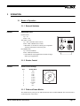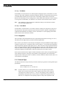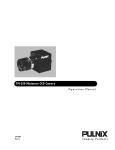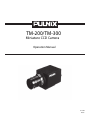
1
TM-200/TM-300
Miniature CCD Camera
Operation Manual
69-0047
Re v. B
Notice
The material contained in this manual consists of information that is proprietary to JAI PULNiX, Inc., and may only
be used by the purchasers of the product. JAI PULNiX , Inc. makes no warranty for the use of its product and assumes
no responsibility for any errors which may appear or for damages resulting from the use of the information contained
herein. JAI PULNiX , Inc. reserves the right to make changes without notice.
Warranty
All of our solid state cameras have a full three year warranty. If any such product proves defective during this warranty
period, JAI PULNiX , Inc. will repair the defective product without charge for parts and labor or will provide a
replacement in exchange for the defective product. This warranty shall not apply to any damage, defect or failure caused
by improper use or inadequate maintenance and use.
Certifications
UL
CE
FCC
This equipment has been tested and found to comply with the limits for a Class A digital device, pursuant to Part 15 of the
FCC Rules. These limits are designed to provide reasonable protection against harmful interference when the equipment
is operated in a commercial environment. This equipment generates, uses and can radiate radio frequency energy and, if
not installed and used in accordance with the instruction manual, may cause harmful interference to radio communications. Operation of this equipment in a residential area is likely to cause harmful interference in which case the user will
be required to correct the interference at his own expense.
WARNING
Changes or modifications to this unit not expressly approved by the party responsible
for FCC compliance could void the user’s authority to operate the equipment.
TM-200 Operation Manual
JAI PULNiX, Inc.
625 River Oaks Parkway
San Jose, CA 95134
Tel: (408) 383-0300
Tel: (800) 445-5444
Fax: (408) 383-0301
Table of Contents
1 INTRODUCTION
1.1
1.2
1.3
1.4
1.5
Product Description .......................................................................... 1
Features ........................................................................................... 1
Functional Options ........................................................................... 2
Applications ...................................................................................... 3
System Configuration ....................................................................... 3
2 INSTALLATION
2.1
2.2
3.2
..................................................................... 4
Getting Started ................................................................................. 4
2.1.1 Unpacking Instructions ........................................................ 4
2.1.2 Components List ................................................................. 4
2.1.3 Accessories ......................................................................... 4
Camera Setup .................................................................................. 5
2.2.1 Connector Pin Configurations ............................................. 5
2.2.2 Power Supply and Power Cable Setup ................................ 5
2.2.3 Attaching the Video Output ................................................. 7
2.2.4 Attaching the Camera Lens ................................................. 7
2.2.5 Back Focusing the Lens ...................................................... 7
2.2.6 Auto-Iris Lens Setup ............................................................ 7
2.2.7 Monitor Display Mode .......................................................... 7
2.2.8 Connectors and Cables ....................................................... 8
3 OPERATION
3.1
.................................................................... 1
.......................................................................... 9
Modes of Operation .......................................................................... 9
3.1.1 External Switches ................................................................ 9
3.1.2 Shutter Control .................................................................... 9
3.1.3 Field and Frame Modes ...................................................... 9
3.1.4 Integration ........................................................................... 10
3.1.5 External Sync ...................................................................... 10
3.1.6 Timing ................................................................................. 11
3.1.7 Interfacing to Frame Grabbers ............................................ 12
3.1.8 Sync Output and Clock Output ............................................ 12
Board Layout and Adjustment .......................................................... 12
3.2.1 Processor Board ................................................................. 12
3.2.2 Mother Board ...................................................................... 12
4 TROUBLESHOOTING
4.1
4.2
Problems and Solutions ................................................................... 14
4.1.1 Symptom: No Video ............................................................. 14
4.1.2 Symptom: Dark Video .......................................................... 14
4.1.3 Symptom: Non-synchronized Video .................................... 14
Information and Support Resources ................................................ 15
5 APPENDIX
5.1
........................................................... 14
............................................................................. 16
Specifications
................................................................................... 16
i
Table of Contents
5.2
5.1.1 Product Specifications ......................................................... 16
5.1.2 Physical Dimensions ............................................................ 17
5.1.3 Glass Specifications ............................................................ 17
5.1.4 C-Mount Specifications ........................................................ 17
5.1.5 Front End Detail ................................................................... 19
Spectral Response ........................................................................... 20
ii
List of Figures
FIGURE 1.
TM-200 System Configuration
................................................... 3
FIGURE 2.
12P-02 Interface Cable (optional)
FIGURE 3.
TM-200 Rear Panel
FIGURE 4.
Shutter Control Settings
FIGURE 5.
Input Signals
FIGURE 6.
TM-200/TM-300 Timing Chart
FIGURE 7.
Processor Board
FIGURE 8.
Physical Dimensions
FIGURE 9.
Camera Front End - Glass Specifications
FIGURE 10.
C-Mount
FIGURE 11.
Combination With “CS-Mount” Camera
FIGURE 12.
Front End Detail
FIGURE 13.
Front End Assembly
...................................................................19
FIGURE 14.
Spectral Response
.....................................................................20
.............................................. 6
....................................................................9
............................................................. 9
..............................................................................11
.................................................... 11
........................................................................12
..................................................................17
.................................. 17
.....................................................................................17
iii
...................................... 18
.........................................................................19
June 15, 1998
TM-200 / TM-300
Miniature CCD Camera
Operations Manual
1
INTRODUCTION
1.1 Product Description
The TM-200/300 is designed to be a simple yet high quality camera capable of meeting a variety of
application requirements. Featuring an advanced Had-type interline transfer 1/2" CCD imager, this
miniaturized high resolution camera offers many standard and optional features at a very affordable
price. It is available in both EIA (TM-200) and CCIR (TM-300) formats.
1.2 Features
•
Variable electronic shutter and random CCD integration.
The substrate drain-type shutter mechanism provides a superb picture at various speeds without
smearing. The electronic shutter rate can be externally adjusted, from 1/60 to 1/10,000 in discrete
steps, via a manually controlled dial switch.
•
Miniaturized and lightweight.
The use of a CCD image sensor in the video camera module and the development of special mini
C-mount lenses makes it possible to produce a very compact, lightweight and robust camera small
enough to operate just like a remoted head.
•
High sensitivity.
The TM-200/TM-300 camera is one of the most low light sensitive 1/2" CCD cameras available
today. This feature is especially important when using the faster shutter speeds. The CCD detects
images into the near infrared. It requires only 1.0 lux of minimum illumination and 0.5 lux
minimum illumination at maximum gain. In general, this allows use of a higher lens f-value while
providing greater depth of field and sharper images.
Page 1
INTRODUCTION
•
Precise image geometry.
On the CCD image sensor, the photosensor elements form exact rows both horizontally and
vertically so that a very precise image geometry may be obtained.
•
Low lag/high resistance to image burning.
Since the CCD is highly resistant to image burning, the camera may be exposed to bright objects
for a long period of time. Because a “smear” phenomena may occur when shooting a very bright
object, an infrared cutoff filter is recommended to obtain a clear picture.
•
AGC selection, manual gain control and gamma adjustment.
These adjustments, which are particularly important in vision system applications, are externally
adjustable via switches on the rear plate.
•
Genlock circuit.
A genlock circuit is built in to accept external sync for applications in which external sync is
required.
•
High resistance to magnetic field and vibration/mechanical shock.
Due to its ruggedized design, the CCD imager can withstand strong vibration and shock with little
or no noise appearing in the picture. Since the TM-200/TM-300 is not influenced by a magnetic
field, it will produce stable images even when placed next to objects such as electric furnaces,
welding machines or NMR scanners.
•
Quick start-up and low power consumption.
No more than 2 seconds is needed for the TM-200/TM-300 to warm up, and shooting can begin
within a second after turning on the camera. The power consumption is only 3.0W. This makes the
camera excellent for use with battery operated systems.
•
Three Year Warranty
The CCD solid state image sensor allows the camera to maintain a superior performance level
indefinitely while requiring virtually no maintenance. PULNiX backs all of the TM Series cameras
with a three-year warranty.
Warning:
Unscrewing the camera cover or opening the camera in any way
will void this warranty.
1.3 Functional Options
Page 2
•
Internal IR Cut Filter (OP3-1)
•
Pixel Clock Output (OP7-2)
•
Glassless CCD Imager (OP21)
•
DC Coupled (OP72)
TM-200 / TM-300 Miniature CCD Camera
INTRODUCTION
1.4 Applications
The miniature size of the TM-200/TM-300 camera eliminates the need for a remoted imager camera in
all but the most confined spaces. This camera fits easily, both physically and functionally, into all types
of machine vision, automated inspection, and related applications. Other uses include remotely piloted
vehicles, miniature inspection devices, surveillance, microscopes and medical equipment.
1.5 System Configuration
Figure 1 (below) presents a typical system configuration in which a computer and frame grabber board
are used. A computer and frame grabber board are not required for operation of the TM-200/TM-300
camera.
FIGURE 1.
TM-200 System Configuration
SHUTTER
SPEED
GAIN
9 0 1
8
2
3
7
6 5 4
VIDEO
1.0
Power
Ext. Sync
Integration
Video Output*
AGC FLD
0.45 MGC FRM
POWER
Computer with
Frame Grabber
Board
Monitor
* Video Output is the
same as BNC connector
TM-200 / TM-300 Miniature CCD Camera
Page 3
INSTALLATION
2
INSTALLATION
The following instructions are provided to help you to set up your video camera system quickly and
easily. It is suggested that you read through these instructions prior to unpacking and setting up your
camera system
2.1 Getting Started
2.1.1 Unpacking Instructions
It is recommended that the original packing cartons for the cameras and lenses be saved in case there is
a need to return or exchange an item.
It is also recommended that any equipment being sent to another location for field installation be bench
tested to assure that everything is fully operational as a system.
2.1.2 Components List
Please begin by checking your order against the Components List (below) to assure that you have
received everything as ordered, and that nothing has been overlooked in the packing materials. If any
item is missing, please contact your PULNiX representative immediately.
•
TM-200 camera
•
TM-200 data sheet
•
TM-200 operations manual
2.1.3 Accessories
Following is a list of additional accessories or equipment that may be recommended or required for your
particular application. Please check with your PULNiX representative prior to the installation of your
video system to determine what you might need.
Page 4
•
Power Cable: 12P-02 Interface Cable
•
Power Supply: PD-12P, PD-12P, DC-12N, or K25-12V
TM-200 / TM-300 Miniature CCD Camera
INSTALLATION
2.2 Camera Setup
2.2.1 Connector Pin Confi gurations
2.2.1 (a)
12-Pin Connector
1
The TM-200 has a 12-pin connector for power input. Generally, Pin #1 is
Ground and Pin #2 is +12V DC. The other pins handle a number of other input
and output functions, which will be discussed further in other sections.
Pin
Description
Pin
Description
1
GND
7
VD Input
2
+12V DC
8
GND
3
GND
9
HD Input
4
Video Out
10
N/C
5
GND
11
Integration
6
N/C
12
N/C
2
3
9
11
4
8
10
7
12
6
5
2.2.2 Power Supply and Power Cable Setup
2.2.2 (a)
Power Supplies
PULNiX recommends the following power supplies:
K25-12
110V AC/12V DC
2.1A power supply
P-15-12
220V AC/12V DC
2.1A power supply
K50-12
110V AC/12V DC
4.2A power supply
PD-12P
110V AC/12V DC
0.5A power supply
For users providing power through the 12-pin connector, the PD-12P power supply is available with the
12-pin mating connector already attached to the leads from the power supply. The PD-12 power supply
can be connected to the PULNiX power cable via a terminal strip or directly.
When wiring the PD-12 power supply directly, please note the following:
•
Twist the lead ends together and tin solder for strength and electrical continuity.
•
Use shrink tubing or a similar insulator to prevent exposed leads from touching.
•
The +12V lead is marked with a red stripe or white lettering; be sure not to reverse the leads.
•
Properly insulate all connections to prevent shorting.
2.2.2 (b)
PULNiX Power Cables
If you are using PULNiX power cables, such as the 12P-02, KC-10, etc., please refer to the pin-out
diagram. The color coded leads use Grey for Ground and Yellow for +12V DC.
TM-200 / TM-300 Miniature CCD Camera
Page 5
INSTALLATION
FIGURE 2.
12P-02 Interface Cable (optional)
Flying
Leads
32mm
1
2,000mm± 10mm
(2 Meters)
1 PC-12P (Hirose Part #10A-10P-12S/PC12P)
12P-02 Interface Cable
Note:
Pin#
Lead Color
Function
Pin#
Lead Color
Function
1
Gray
GND
7
Black coax
VD Input
2
Yellow
+12VCD
8
White coax shield
GND
3
Red coax shield
GND
9
White coax
HD Input
4
Red coax
Video
10
Brown
N/C
5
Orange coax shield
GND
11
Blue
Integration
6
Orange coax
N/C
12
Black coax shield
N/C
Make sure that the unused leads are not touching and that there is no possibility that the
leads could short due to exposed wires.
2.2.2 (c)
“K” Series Power Supplies
Attach the 110V line cord to the two terminals marked “AC”. Do not plug the cord into a 110V AC
socket until later in the procedure. Next, attach the Grey and Yellow leads of the power cable to the
Ground and 12V DC terminals respectively. Be sure to replace the plastic terminal guard on the power
supply at this time.
Note:
The “K” series power supplies are designed primarily for OEM users who will be
mounting the power supply inside a protective enclosure. For use in exposed situations,
the DC-12N and PD-12 are recommended.
2.2.2 (d)
Building Your Own Power Cable
Consult the pin-out for the camera purchased. Connect the Ground and +12V power leads of the PC12P power connector to Pin #1 and Pin #2, respectively (power must be DC regulated, and of sufficient
current to properly power the camera).
2.2.2 (e)
Attaching the Power Cable to the Connector
The 12-pin connector is keyed and will only fit in one orientation. Rotate the connector while applying
slight pressure until the keyways line up. Press the connector into place until firmly seated.
The power cord may now be plugged into the 100V AC socket, and the camera powered up.
Page 6
TM-200 / TM-300 Miniature CCD Camera
INSTALLATION
2.2.3 Attaching the Video Output
Most users utilize the BNC connector for video output from the camera. Connect the output from the
camera to the input of your monitor, VCR or switching device. The input of the monitor should be
balanced for 75Ω termination. Standard RG-59 type coaxial cable should carry a full video signal for up
to 500 feet.
Users wishing to output the video and input the power and sync to a camera over a single cable can use
the PULNiX multi-conductor cables, such as the 12P-02, the KC-10, etc. The mini coaxial leads in
PULNiX multi-conductor cables are designed for short runs of no longer than 100 feet.
Note: Make sure that no extraneous wires are visible which could cause a short.
2.2.4 Attaching the Camera Lens
The TM-200/TM-300 camera accepts 1/2" or larger format size C-mount lenses. To attach the C-mount
lens to the camera, carefully engage the threads and rotate the lens clockwise until it firmly seats on the
mounting ring. Do not force the lens if it does not seat properly. Please note that some lenses with
extremely long flangebacks may exceed the mounting depth of the camera.
2.2.5 Back Focusing the Lens
To backfocus the TM-200 camera, first attach a C-mount lens in the lens mount. Be sure that the lens is
properly mounted.
Set the lens focus to infinity (if the lens is a manual iris, set the iris to a low f-stop while still retaining a
well-illuminated image). Obtain the best focus possible at this setting, then loosen the 3 miniature hex
head set screws locking the focus ring in place. Now turn the entire lens and focus ring assembly back
and forth until the best image is obtained. Tighten the focus ring set screws. Your backfocus is now set.
2.2.6 Auto-Iris Lens Setup
Auto-iris lenses with full video input can be used with the PULNiX TM-200, although this camera
model does not come equipped with auto-iris output.
Note:
Make sure that the power is removed from the camera before connecting or disconnecting
the auto-iris lens. There is a small chance that damage could occur to the auto-iris lens by
plugging or unplugging it while the camera is powered up.
Power down the camera before installing the auto-iris lens. To install the auto-iris lens in a PULNiX
camera for which the auto-iris input is not supplied, wire the signal (video) on the lens into the terminal
1 Vp to peak video output on the camera.
Point the camera at a light area and then quickly towards a darker area. If everything is working
properly, the iris should adjust for the light change.
2.2.7 Monitor Display Mode
For monitoring real time video, connect the video output to a video monitor or other device.
TM-200 / TM-300 Miniature CCD Camera
Page 7
INSTALLATION
2.2.8 Connectors and Cables
12-pin connector and cable: Standard cable is 12P-02 (2m, 8 conductor cable) for power and external
controls.
Page 8
TM-200 / TM-300 Miniature CCD Camera
OPERATION
3
OPERATION
3.1 Modes of Operation
3.1.1 External Switches
FIGURE 3.
TM-200 Rear Panel
Gamma switch
Up = 1.0
Down = 0.45
AGC/MGC switch
Up = AGC (Automatic Gain Control)
Down = MGC (Manual Gain Control)
* When MGC is selected, the camera gain is adjustable
with the potentiometer on the back plate.
FLD/FRM Switch
Up = FLD (Field Mode)
Down = FRM (Frame Mode)
* Select FRM for strobe applications and FLD for high
shutter speed applications.
SHUTTER
SPEED
GAIN
9 0 1
8
2
3
7
6 5 4
VIDEO
1.0
AGC FLD
0.45 MGC FRM
POWER
3.1.2 Shutter Control
FIGURE 4.
Shutter Control Settings
Set
Shutter Mode
0
1
2
3
4
5
6
7
8
9
1/60
1/125
1/250
1/500
1/1,000
1/2,000
1/4,000
1/10,000
N/C
N/C
9
0
1
8
2
7
3
4
6
5
Shutter Control Switch
3.1.3 Field and Frame Modes
The standard factory setting for the TM-200/TM-300 camera is FIELD MODE. The mode selection is
on the back panel of the camera.
TM-200 / TM-300 Miniature CCD Camera
Page 9
OPERATION
3.1.3 (a)
Field Mode
In Field Mode, two horizontal rows are scanned together, changing the pair at each interlace scan. The
sensitivity of the CCD is doubled for one field of integration, therefore it can obtain the same sensitivity
as in Frame Mode in half the period of time. This is an advantage when the shutter is used often.
Because of the alternating two row scanning, Moire is almost unnoticeable. While the vertical resolution
is not as good as in Frame Mode, it is sufficient to view the full vertical resolution of the TV format.
Note:
Only odd fields are output in this mode. Field Mode cannot provide full frame resolution
with strobe lighting applications.
3.1.3 (b)
Frame Mode
In Frame Mode, each horizontal row is scanned as interlace scanning. The integration of each pixel is
one frame period. Vertical pixel resolution is good, and exact location is obtained. A disadvantage as
compared with Field Mode is the tendency to show vertical Moire. For strobe lighting, Frame Mode
must be used to achieve full frame resolution.
3.1.4 Integration
The CCD imager of the TM-200/TM-300 can be exposed longer than normal TV timing (16.7 msec.).
This feature provides high sensitivity for dark environment applications.
Pin #11 of the 12-pin connector is the control pin for integration. It accepts standard TTL inputs. High is
considered 5 Volts and Low is considered 0 Volts. You may enable (i.e., not actually start integrating an
image) integration by applying a high signal to pin #11. Then, when a low voltage is applied to the same
pin #11, the integration process begins. Integration blocks the transfer gate of the image data out of the
CCD array. Think of a transfer gate(sg) as a floodgate that lets water out of a lake (CCD array). Upon
returning the signal back to high which is required to end the process, the image is output.
Set the camera in frame mode to output two fields of information. In this mode, the output fields appear
to have different exposures, so this may cause problems in some applications. Set to field mode to
output one frame with only one frame of resolution, one field is doubled to obtain one frame (this is not
a true full frame of information).
3.1.5 External Sync
The TM-200/TM-300 can accept external sync from an external sync generator or frame grabber. Input
specifications:
Internal/External auto switch
fH+15.734 KHz ±5%, fV +59.95 Hz ±5%
Note:
Page 10
The TM-300 has a one (1) horizontal line delay between the input VD signal and the
output video. If external vertical drive (VD) is applied to the camera, it may cause the
video output to be delayed 1 HD (1 H = ~64.0 µs). If the imaging system is capable of
automatically detecting the start of video (within a few HD), then no problem will exist.
Otherwise, re-configure the video capturing sequence to delay video acquisition of 1H.
TM-200 / TM-300 Miniature CCD Camera
OPERATION
FIGURE 5.
Input Signals
1/f(horizontal)
+5Volts HD
TTL Level
0 Volts
3 - 5µsec.
1/60
+5Volts VD
TTL Level
0 Volts
1 to 9H
3.1.6 Timing
FIGURE 6.
TM-200/TM-300 Timing Chart
HD
6.7µSec
818
768
B45
45
757
758
759
760
761
762
763
764
765
766
767
768
5
B1
B2
B3
B4
B5
1
2
3
4
5
6
7
8
9
10
D1
22
D22
70
B45
B1
763
764
765
766
767
768
45
B1
96
6
CCD photo sensors
allocation
Optical
black period
H register
stop period
69.8nSec
Image sensing period
Dummy
H register
Optical
black period
CCD output
signal
Effective picture
period
154
H BLK 10.7µSec
Composite video
output
22
1.54µSec
68
H SYNC
4.75µSec
64
4.47µSec
910
63.56µSec
TM-200 / TM-300 Miniature CCD Camera
756
52.81µSec
(1 horizontal line)
Page 11
OPERATION
3.1.7 Interfacing to Frame Grabbers
12-pin connector or BNC.
3.1.8 Sync Output and Clock Output
TTL level internal sync and buffered pixel clock output (14.31818MHz) are available from the TM-200/
TM-300 camera. The signal is an emitter follower output requiring a termination resistor at the end of
the cable. The suggested value is from 75Ω to 330Ω.
3.2 Board Layout and Adjustment
3.2.1 Processor Board
Connect Processor Board to test jig and check all functions.
Voltage Setting
AGC
MGC
Adjust VR1 (AGC) so that the pot. is 2.0V.
Set VR3 (MGC) at mechanical center (2.5V at pot.). Then set ext. gain pot.
(rear panel) to 3.6V at pot.
Mechanical center
AGC MAX. Adjust VR2 (AGC MAX) to 3.±0.1V at pot.
FIGURE 7.
Processor Board
VR1
VR2
AGC
AGC MAX
VR3
MGC
3.2.2 Mother Board
External Sync Specification
Page 12
TM-200 / TM-300 Miniature CCD Camera
OPERATION
Sync
HD in
Internal/External auto-switching
fHD = 15.734 KHz ± 5% (EIA)
fHD = 15.625 KHz ± 5% (CCIR)
VD in
fVD = 59.94 Hz ± 5% (EIA)
fVD = 50.00 Hz ± 5% (CCIR)
Input impedance 200Ω
TM-200 / TM-300 Miniature CCD Camera
Page 13
TROUBLESHOOTING
4
TROUBLESHOOTING
4.1 Problems and Solutions
Following are troubleshooting tips for common problems. Generally, problems can easily be solved by
following these instructions. If the following remedies fail to offer a solution to your problems, please
contact a PULNiX representative.
4.1.1 Symptom: No Video
Remedies: Check that the following are properly connected and operational.
•
Power supplies
•
Power cables
•
Main power source
•
Shutter control
•
Async mode
•
Lens
4.1.2 Symptom: Dark Video
Remedies: Check that the following are properly connected and operational.
•
Shutter selection
•
Iris opening on the lens
4.1.3 Symptom: Non-synchronized Video
Remedies: Check that the following are properly connected and operational.
Page 14
•
Proper mode output
•
Frame grabber software camera selection
TM-200 / TM-300 Miniature CCD Camera
TROUBLESHOOTING
4.2 Information and Support Resources
For further information and support:
Phone:
(408) 383-0300
(800) 445-5444
Fax:
(408) 383-0301
E-mail:
[email protected]
Mail:
JAI PULNiX Inc.
Sales Department
625 River Oaks Parkway
San Jose, CA 95134
Web Site:
TM-200 / TM-300 Miniature CCD Camera
www.jaipulnix.com
Page 15
APPENDIX
5
APPENDIX
5.1 Specifications
5.1.1 Product Speci fications
TABLE 1.
TM-200/TM-300 Product Speci fications Table
Model
Imager
TM-300 (CCIR)
1/2" Interline transfer CCD, HAD type
Pixels
768(H) x 494(V)
752(H) x 582(V)
Cell size
8.4µm x 9.8µm
8.6µm x 8.3µm
Scanning
525 lines EIA
625 lines CCIR
Sync
TV resolution
S/N Ratio
Min. illumination
Video output
Internal/External auto switch
fH=15.734 KHz ±5%,
fV=59.95 Hz ±5%
fH=15.725 KHz ±5%,
fV=50 Hz ±5%
570(H) x 350(V)
560(H) x420(V)
50dB min., 56dB typical, AGC off
0.5 lux (F=1.4)
1.0 Vp-p composite video, 75Ω
AGC
ON/OFF back panel switch
Gamma
1 or 0.45 back panel switch
Lens mount
C-mount
Power requirement
190 mA, 11-15V
Operating temp.
-10°C to +50°C
Vibration & Shock
Size
Weight
Power cable
Power supply
Page 16
TM-200 (EIA)
Vibration 7Grms/20-2000 Hz, Shock 70G
45.8mm x 39.4mm x 66.3mm
1.81" x 1.54" x 2.60"
157g (5.6 oz.)
12P-02 (optional)
k25-12V, DC-12N, PD-12
Functional options
3-1, 3-2, 7-2, 21, 25
Accessories
See current price list.
P-15-12
TM-200 / TM-300 Miniature CCD Camera
APPENDIX
5.1.2 Physical Dimensions
FIGURE 8.
Physical Dimensions
78.9 mm
45.8 mm
2X 11.0 mm
66.3 mm
1/4-20 UNC-2B
39.4 mm
7.0 mm
2xM6x10
30.4 mm
2xM3x10
5.1.3 Glass Specifications
FIGURE 9.
Camera Front End - Glass Specifications
CCD Glass (BK-7) 0.75mm thickness
Refractive Index = 1.5
Glass Cover (BD-65) 1.0mm thickness
Refractive Index = 1.51
CCD
CCD Glass
5.1.4 C-Mount Speci fications
FIGURE 10.
C-Mount
TM-200 / TM-300 Miniature CCD Camera
Page 17
APPENDIX
The Flange Back Length of the CS-Mount is 12.5mm versus 17.526 of the C-Mount. The shorter Flange
Back Length of the “CS-Mount” allows room for the stripe filter incorporated in the color camera.
Additionally, the shorter Flange Back Length allows for reduction of the effective diameter of the first
lens and reduces the number of lens elements. The common C-Mount lens is completely compatible
with a CS-Mount camera when a 5mm extension ring is inserted between the lens and the camera.
FIGURE 11.
Combination With “CS-Mount” Camera
CS-Mount Lens
Focal Point
5mm Extension Ring
C-Mount Lens
5
12.5
17.526
Flange Surface of
C-Mount
Page 18
TM-200 / TM-300 Miniature CCD Camera
APPENDIX
5.1.5 Front End Detail
FIGURE 12.
Front End Detail
18.20
Front End
1.00
Image Plane
C-Mount Ring
CCD Imager
16.8
1.41
FIGURE 13.
Front End Assembly
C-MOUNT
RING
I.C.
2X MOUNTING
HARDWARE
PIN 1
FRONT
END
3X C-MOUNT RING
LOCKING SET SCREW
TM-200 / TM-300 Miniature CCD Camera
Page 19
APPENDIX
5.2 Spectral Response
FIGURE 14.
Spectral Response
1.0
O.9
0.8
0.7
Relative Sensitivity
0.6
0.5
0.4
0.3
0.2
0.1
0
400
Page 20
500
600
700
800
900
1000
1100
1200
Wave Length (nm)
TM-200 / TM-300 Miniature CCD Camera
Industrial Products Division
JAI PULNiX Inc.
625 River Oaks Parkway
San Jose, CA 95134
Tel: 408-383-0300
Tel: 800-445-5444
Fax: 408-383-0301
Email: [email protected]
www.pulnix.com