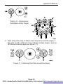
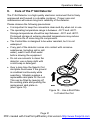
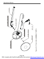
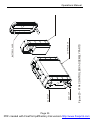
1
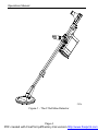
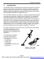
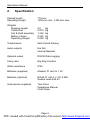
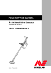
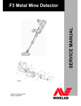
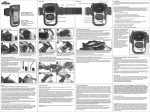
WARNING THIS DOCUMENT CONTAINS MINELAB ELECTRONICS PTY LIMITED RIGHTS TECHNICAL DATA OR RESTRICTED RIGHTS DATA OR BOTH. Minelab Electronics This work is copyright. Apart from any use as permitted under the Copyright Act 1968, no part may be reproduced by any process without written permission from Minelab Electronics Pty Ltd 118 Hayward Avenue, Torrensville, SA 5031 Australia PDF created with FinePrint pdfFactory trial version http://www.fineprint.com PDF created with FinePrint pdfFactory trial version http://www.fineprint.com Operations Manual LIST OF CONTENTS 1. Introduction ................................ ................................ .................. 5 2. Specification................................ ................................ ................. 6 3. List of Parts ................................ ................................ .................. 9 4. Unpacking and Assembly ................................ ............................ 11 4.1 Shaft Assembly ................................ ................................ .....11 4.2 Control Box ................................ ................................ ...........13 4.3 Armrest ................................ ................................ .................15 4.4 Battery Pack................................ ................................ ..........17 4.5 Comfort Adjustments ................................ ............................ 18 5. Operating Instructions ................................ ................................ .19 5.1 Control Panel Description................................ ...................... 19 5.2 Detector Settings ................................ ................................ ..21 5.3 Detector Sounds ................................ ................................ ...24 5.4 Testing Procedure / Using the Test Piece ............................. 25 5.5 Sweeping the Coil ................................ ................................ .27 5.6 Pinpointing the Position of a Small Target............................. 27 5.7 Pinpointing Large or Multiple Targets................................ ....28 5.8 Operating Multiple Detectors in Close Proximity....................30 6. Care of the F1A4 Detector................................ .......................... 31 6.1 Operator Repairs ................................ ................................ ..32 7. Exploded Views of Assembly Parts Diagrams ............................. 33 Page 3 PDF created with FinePrint pdfFactory trial version http://www.fineprint.com Operations Manual Figure 1 - The F1A4 Mine Detector Page 4 PDF created with FinePrint pdfFactory trial version http://www.fineprint.com Operations Manual 1. Introduction The Minelab range of metal detectors has been developed to meet the needs of today“s mine and explosive ordnance clearance operations. Minelab has built its experience in the minefields of South East Asia, where its technology has been exposed to the harshest environments, including highly mineralised, magnetic ground. The F1A4 Mine Detector (see Figure 1) has been specifically designed to provide semi-automatic ”switch and go— operation. The equipment automatically adjusts Ground Balance, Threshold (Audio) and Fine Frequency (Noise Cancel), leaving the operator free to concentrate on other tasks. The F1A4 detector also has the ability to be used with as many as 10 units operating in close proximity. The detector has been designed and built to meet de-mining requirements and incorporates safety features such as ”Low Battery— warning, audible ”OK— signal at the end of setting cycles and includes a standard ”Test Piece—. The main components of the detector are manufactured within tightly controlled parameters so that they can be interchanged in the field without any requirement for calibration. The equipment is supplied as a Mine Detecting Set (see Figure 2) comprising: ‘ the detector, ‘ a carry case, ‘ an ear set, ‘ a test piece, ‘ an operations manual, and ‘ field guide. Figure 2 - The F1A4 Mine Detecting Set Page 5 PDF created with FinePrint pdfFactory trial version http://www.fineprint.com Operations Manual 2. Specification Packed length Operating Length 710 mm 1200 mm min - 1450 mm max. Weights Shipping weight Control box Coil & shaft assembly Battery Carrier Operating Weight 4.0 0.875 1.326 0.225 2.900 Transmission Multi Period Pulsing Audio outputs Ear Set Internal Speaker Optional output RS232 Data Logging Carry case Rip Stop Cordura Water resistance IP65 Batteries (supplied) Alkaline –D“ cell 4 x 1.5V Batteries (optional) NiCad –D“ cell 4 x 1.2V 4.5Ah Sealed Lead Acid 6V Accessories (supplied) Test Piece Operations Manual Field Guide Kg Kg Kg Kg Kg Page 6 PDF created with FinePrint pdfFactory trial version http://www.fineprint.com Operations Manual Accessories (optional) Rechargeable Batteries Battery Charger 6V SLA Battery Charger (Commercial) F Series Battery Charger Ear Set °Loudspeaker Off Ear Set °Loudspeaker On Hard Transport Case (6 unit) Hard Transport Case (1 unit) Temperature (operating) -30oC to +60oC Temperature (storage) -55oC to +90oC Patents US4890064, US4894618 AUS595835, CAN1260146 Page 7 PDF created with FinePrint pdfFactory trial version http://www.fineprint.com Operations Manual EARSET FIELD GUIDE F1A4 BAG CONTROL BOX OPERATIONS MANUAL F1A4 ARMREST BAG COMPACT 'D' CELL BATTERIES (4) CONTROL BOX TEST PIECE MINE DETECTOR P0141-C Figure 3 - The F1A4 Carry Bag and Parts Assembly Page 8 PDF created with FinePrint pdfFactory trial version http://www.fineprint.com Operations Manual 3. List of Parts (see Figure 3) The F1A4 Mine Detecting Set comprises the following parts: This list is not comprehensive: MINELAB PART NO 0304-0004 0703-0046 2003-0010 2018-0022 3001-0011 3001-0018 3012-0052 4001-0003 4002-0003 4005-0008 4308-0004 4523-0019 4523-0024 4901-0025 4903-0015 8001-0005 8001-0007 8007-0015 8012-0005 8701-0002 DESCRIPTION F1A4 Battery Carrier Batt Cover Assy With Strap Skidplate 200mm Khaki Coil Incl Lower Shaft & Nut & Bolt Bag Compact Grey Bag Control Box Grey Control Box F1A4 V8 Nylon Bolt Black Nylon Nut Wing Black Washer Friction ea Lock-pin Control Box Earset Speaker On Earset Speaker Off Operations Manual F1A4 Field Guide F1A4 Armrest Sq Shaft Armstrap Lower Shaft Main Shaft Test Piece Mine Detector Optional Accessories 0302-0035 0302-0036 0302-0040 0302-0041 0302-0042 0303-0004 0303-0010 5305-0016 5305-0010 Charger Hye 4 D Cell Aus Charger Hye 4 D Cell Euro F Series Charger 8 D Cell Aus F Series Charger 8 D Cell US F Series Charger 8 D Cell Euro Battery Alkaline D Cell Battery Rechargeable D Cell Multi Unit (6) Hard Case UN Blue Single Unit Hard Case If you have any questions concerning spare parts please contact Minelab direct (see back cover for details). Page 9 PDF created with FinePrint pdfFactory trial version http://www.fineprint.com Operations Manual Figure 4 - The F1A4 Shaft Assembly Page 10 PDF created with FinePrint pdfFactory trial version http://www.fineprint.com Operations Manual 4. a. b. c. Unpacking and Assembly Open the shipping container and remove the carry bag. Open the carry bag and check all standard and optional components are present and undamaged. Remove the components and assemble the detector in the following sequence. 4.1 Shaft Assembly (see Figure 4) a. b. c. d. e. Remove the armrest from the carry bag. Remove the main shaft (including handle) and lower shaft (including coil) from the carry bag. The two shaft assemblies are interconnected by the coil cable that runs through the inside of these hollow components. Ensure the coil cable is fully within the cable groove in the lower shaft. Release the lower camlock lever on the bottom end of the main shaft, position and slide the small end of the lower shaft inside the main shaft to the desired length and clamp these two components together by closing the lower camlock lever. Before attaching the armrest, decide how the Control Box is to be positioned. (See Figure 6 for correct coil cable positioning.) Release the upper camlock lever at the top end of the main shaft, position the selected grommet on the coil cable into the keyway in the upper camlock, place the end of the armrest inside the main shaft and clamp these two components together by closing the upper camlock lever. NOTE: It is not necessary to pull the cable through the top of the main shaft if the control box is to be connected to the handle. However, if the cable is pulled through, twisting the coiled section of the cable to ”tighten— the coil will make reinsertion of the cable easier. To repack the detector in its carry bag, pack the components in the following sequence: • Folded main and lower shaft • Control Box • Armrest Page 11 PDF created with FinePrint pdfFactory trial version http://www.fineprint.com Operations Manual Figure 5 - Control Box Configurations Page 12 PDF created with FinePrint pdfFactory trial version http://www.fineprint.com Operations Manual 4.2 Control Box (see Figure 5) The Control Box can be positioned in one of three locations: • it can be placed in its control box bag which is attached to the operator“s waist via two belt loops; • when the webbing strap is used, the control box bag can be worn over the operator“s shoulder, or it can hang around the operator“s neck; or • it can be attached to the main shaft via a locking bracket located beneath the handle. a. If the control box bag is to be used to carry the Control Box either worn on the belt or as a shoulder pack, position the grommet (located between the two curled sections of the coil cable) into the keyway beneath the camlock at the top end of the upper shaft. (See Figure 6 for correct coil cable positioning.) The plug end of the coil cable is then connected to the socket marked Coil on the Control Panel. b. If the Control Box is to hang beneath the handle on the main shaft, the mounting block on the Control Box is pushed into the locking bracket immediately beneath the handle. Rectangular lugs on the mounting block snap into rectangular holes on the sides of the locking bracket to hold the Control Box loosely in position. To lock the bracket, turn the locking pin fully clockwise until it locks in position. The plug end of the coil cable is then connected to the socket marked Coil on the Control Panel. c. To remove the Control Box when it is attached to the underside of the handle it is necessary to disconnect the coil cable, and then turn the locking pin counter-clockwise to release the Control Box. Page 13 PDF created with FinePrint pdfFactory trial version http://www.fineprint.com Operations Manual Figure 6 - Armrest Configurations Page 14 PDF created with FinePrint pdfFactory trial version http://www.fineprint.com Operations Manual 4.3 Armrest (see Figure 6) To assemble the armrest: a. Insert the sharp end of the arm strap through one of the slots at the base of the armrest, then through the slots at the top of the wings of the armrest. When the operator“s arm is in the armrest, the protruding part of the –Velcro“ strap should be fixed to make a firm fit. b. Decide whether the Control Box is to be attached to the handle or housed in the control box bag, as this will determine what length of coil should protrude from the main shaft. c. If the Control Box is to be attached to the shaft, position the cable grommet closest to the plug end of the coil cable into the keyway beneath the camlock at the top end of the upper shaft. (Surplus coil cable can be stored inside the hollow main shaft.) d. Alternatively, if the Control Box is to be carried in its shoulder pack, position the grommet located between the two curled sections of the coil cable into the keyway beneath the camlock at the top end of the main shaft. e. When the appropriate grommet is positioned in the keyway, push the end of the armrest assembly into the camlock on the top of the main shaft and clamp using the upper camlock lever. NOTE: It is not necessary to pull the cable through the top of the main shaft if the control box is to be connected to the handle. However, if the cable is pulled through, twisting the coiled section of the cable to ”tighten— the coil will make reinsertion of the cable easier. This technique simplifies shaft reassembly. Page 15 PDF created with FinePrint pdfFactory trial version http://www.fineprint.com Operations Manual 'D' Cell Battery Carrier and Cover Battery Cover Remove Battery Cover Snaplocks Control Box Snaplocks Lead-Acid Battery Pack (Optional) Battery Cover Battery Cover Snaplocks Control Box Snaplocks P0019-D Figure 7 - The F1A4 Battery Pack Page 16 PDF created with FinePrint pdfFactory trial version http://www.fineprint.com Operations Manual 4.4 Battery Pack (see Figure 7) The F1A4 can be powered by one of two battery packs. NOTE: Before connecting or disconnecting either battery pack ensure that the unit is switched Off on the Control Panel. 4.4.1 Lead-Acid Battery Pack To use the belt-mounted Lead-Acid battery pack as a power source: a. It is necessary to undo the –snaplocks“ on the base of the Control Box and remove the Battery Carrier and Cover. b. A freshly charged Lead-Acid Battery can then be connected to the Control Box via its supplied cable to the socket marked POWER ACCESSORY that is located on the base of the Control Box. c. The detector can now be switched to Search and operations resumed. 4.4.2 ’D, Cell Battery Pack To use the –D“ cell battery pack as a power source: a. Disconnect the Coil Cable from the Control Box and remove the Control Box from the Control Box Bag or from the handle as applicable (see Paragraph 4.2). b. To gain access to the four –D“ cells it is necessary to release the two –snaplocks“ that secure the battery cover on the battery carrier which can be found on the bottom of the Control Box. c. The cells can now be removed or replaced (using the battery map inside the battery carrier) in accordance with the illustrations on page 16 of this manual. d. The battery cover can now be refitted and the –snaplocks“ engaged. Connect the Control Box to the handle or insert into the Control Box Bag. Reconnect the Coil Cable to the Control Box. e. The detector can now be switched to Search and operations resumed. Page 17 PDF created with FinePrint pdfFactory trial version http://www.fineprint.com Operations Manual 4.5 Comfort Adjustments (see Figure 8) a. Releasing the upper camlock lever at the top end of the main shaft permits up to 50 mm adjustment of the position of the armrest assembly, relative to the handle position. b. Releasing the handle camlock lever at the base of the handle allows the handgrip to be repositioned along the length of the main shaft. c. Releasing the lower camlock lever at the bottom end of the main shaft enables the effective length of the lower shaft to be altered. d. The hand strap can be changed from right to left-handed by unlacing the handstrap and re-inserting the strap from the other side. e. The coil angle can be adjusted without adjusting the clamping nut. CAUTION Ensure the clamping nut is not over tightened. Figure 8 - Comfort Adjustments Page 18 PDF created with FinePrint pdfFactory trial version http://www.fineprint.com Operations Manual 5. Operating Instructions 5.1 Control Panel Description (see Figure 9) All controls are located on the Control Panel. Battery Low Noise Cancel MINELAB Off On Search Balance F1A4 Audio Reset Coil P0024-D Figure 9 - The F1A4 Control Panel 5.1.1 Off / Search / Balance Switch This three-position switch located near the centre of the Control Panel provides the ability to switch the unit On and Off. Normal detection operations are performed whilst in the Search position. The detector is On when it is switched to either Search or Balance: • Search ‘ Using the detector with the switch set to Search means that the setting to cancel ground noise remains fixed. Changing ground conditions may require the detector to be balanced occasionally to cancel any ground noise. • Balance ‘ In this spring-loaded position, ground noises can be cancelled out. WARNING The detector must always be left in Search when actually searching for mines. It is possible that the signal you are attempting to balance out is that of a small or distant target. Page 19 PDF created with FinePrint pdfFactory trial version http://www.fineprint.com Operations Manual 5.1.2 Noise Cancel Noise Cancel negates the effects of electro-magnetic interference. Installations such as local television stations, radar transmitters and electrical power cables emit signals that can interfere with the detector. Performing a Noise Cancel procedure forces the detector to reset itself so as to minimise the effects of any interference. CAUTION When the detector is emitting a repetitive warble without the coil being moved it is necessary to perform a Noise Cancel procedure. The detector will emit random sounds when operated in close proximity to electrical storms, arc welders and other electrical equipment. 5.1.3 Audio Reset The Audio Reset procedure resets the threshold level of the background tone heard from the internal speaker or operator“s earset. The best sound level for detecting mines and other ordnance is a faint constant tone, just above no sound at all. Using Audio Reset achieves this ideal setting, but it is possible for the level to drift. In this instance, an Audio Reset procedure should be performed. 5.1.4 Battery Low This Red LED flashes and the detector emits a loud oscillating tone when the charge in the batteries drops to a predefined, low level. If the F1A4 is operated while the LED is flashing and the oscillating tone can be heard, the unit may become unstable. WARNING The detector must not be used to detect mines and other ordnance while the battery level is low. Page 20 PDF created with FinePrint pdfFactory trial version http://www.fineprint.com Operations Manual 5.2 Detector Settings WARNING Operators should be aware of other electronic equipment being used in the immediate locality that may affect the operation of the detector. To initialise the detector in a new area, switch the detector from Off to Search. The detector takes 6 seconds to run through a set-up routine, and during this time 3 long –beeps“ with a slowly rising pitch can be heard. Once the set-up routine has completed, Noise Cancel, Audio Reset and Ground Balance procedures should be performed as required. Test the detector with the Test-Piece (refer Paragraph 5.4) To restart the detector in the same operating area, switch the unit from Off to Search. The detector will take 6 seconds to turn on, and during this time 3 long –beeps“ with a slowly rising pitch can be heard. The detector is now set with the same settings that were previously used, that is, the same Audio Reset, Noise Cancel and Balance that applied when the unit was last turned Off. Test the detector with the Test-Piece (refer Paragraph 5.4) Leave the detector in Search and proceed according to your established Standing Operating Procedures for de-mining. 5.2.1 Setting the Audio Threshold When the detector threshold gets too loud or too soft (due to extreme temperature change or Noise Cancel resetting), conduct the following Audio Reset control procedure: a. Press the blue Audio Reset button. b. The detector will emit an –eee-aww-eee“ sound when unit has been reset. This procedure will take less than 5 seconds. c. If all other settings have been established, test the detector with the test piece (refer Paragraph 5.4). If the detector test is satisfactory it is now ready for use. CAUTION The F1A4 cannot detect targets while the Audio Reset procedure is being performed. Page 21 PDF created with FinePrint pdfFactory trial version http://www.fineprint.com Operations Manual 5.2.2 Noise Cancel Procedure When the detector gives a repetitive warble without the coil being moved, perform the following electromagnetic Noise Cancel procedure: CAUTION Keep the detector very still; do not handle the detector during this procedure. It can take some time and any movement can upset the process, as will any metallic objects being moved in the vicinity of the coil. Also ensure that there are no metallic objects near the coil during this procedure. a. Place the detector coil flat on the ground and press the blue Noise Cancel button. b. The detector will take 70 seconds to scan the locality and adjust the detector to a quiet setting. During this time, a continuous, steady tone can be heard. c. The detector sounds four beeps once scanning is completed. d. When this procedure is completed it may again be necessary to follow the Audio Reset and Ground Balance procedures to readjust the audio threshold and Ground Balance. e. If all other settings have been established, test the detector with the test piece (as described in section 5.4). If the detector test is satisfactory it is now ready for use. CAUTION The F1A4 cannot detect targets while the Noise Cancel procedure is being performed. Page 22 PDF created with FinePrint pdfFactory trial version http://www.fineprint.com Operations Manual 5.2.3 Ground Balance Procedure (see Figure 10) Ensure that the Noise Cancel and Audio Reset procedures have been performed and then select an area known to be free of metallic particles. a. Place the detector with the coil resting on the ground. b. Turn the On/Off switch to Balance and hold the switch in this position. c. Move the coil slowly up and down from 25 to 100 mm above the ground. Each complete up and down movement should take 3 to 4 seconds. As this movement is repeated, any ground noise will gradually diminish until it is eliminated, i.e. the detector makes no sound when leaving or approaching the ground surface. d. Before resuming search operations the detector switch should be released to Search. This fixes the ground balance to its current setting and prevents it from being shifted by metallic targets in the ground. WARNING While balancing, a persistent signal indicates the presence of a metallic target in the ground. It is possible that the signal you are attempting to balance out is that of a small or distant target. Figure 10 - Adjusting Ground Balance Page 23 PDF created with FinePrint pdfFactory trial version http://www.fineprint.com Operations Manual 5.3 Detector Sounds WARNING The threshold tone is a safety tone and must be present to ensure correct operation of the detector. If there is a persistent change in this tone, the detector should be tested with the test piece before further use of the detector. (see Section 5.4 for further information on testing the detector.) a. Threshold Tone - is the background tone produced by the detector. The loudness of the threshold is set by the in-built microprocessor. When the detector is turned On or after completing the Audio Reset procedure, the threshold tone should be just audible. The volume of the threshold tone will seldom vary from the level set by the microprocessor. If it does vary and is too loud or too soft, repeat the Audio Reset procedure. b. Target Sound - is an abrupt variation of the audio volume and pitch. The pitch of the tone will vary depending on the metal composition and size of the target. (See Figure 11) Figure 11 - Pitch varies as the Coil passes over a target WARNING Target sounds will vary. Different target sounds in the same area may indicate multiple targets. All target sounds must be considered dangerous. Page 24 PDF created with FinePrint pdfFactory trial version http://www.fineprint.com Operations Manual c. Ground Noise - is an irregular broad noise that is difficult or impossible to pinpoint when moving the coil over the ground. d. If ground noise is affecting the operator“s performance, rebalance the detector as described in the Ground Balance procedure. 5.4 Testing Procedure / Using the Test Piece The F1A4 test piece is used to ensure that when the following test is performed, operators can have full confidence that the detector is working to its optimum performance. It should also be noted that under ideal conditions (detector correctly noise cancelled and ground balanced within a quiet background) the test piece will register a clear signal from a greater distance from the centre of the coil. Page 25 PDF created with FinePrint pdfFactory trial version http://www.fineprint.com Operations Manual CAUTION Follow established standing operating procedures at all times, and use the supplied test piece to confirm that the detector registers a correct signal before and after every use. An area that has just been checked with the F1A4 detector should not be considered safe until the detector has been rechecked with the test piece. a. Ensure that the detector is emitting the correct threshold tone. If in doubt, perform Noise Cancel or Audio Reset procedure. b. Make sure your hands and wrists are free of any metallic objects. c. Place the test piece with the end with the hole lightly against the centre of the bottom of the coil. d. Confirm that a distinct signal is registered as the test piece is moved in the directions shown in Figure 12. P0263-B Figure 12 - Using the Test Piece Page 26 PDF created with FinePrint pdfFactory trial version http://www.fineprint.com Operations Manual 5.5 Sweeping the Coil a. While sweeping the coil it is important to keep it parallel to and at a constant height from the ground at all times (see Figure 13). CAUTION Be aware of any tendency to raise the coil at the ends of each sweep as this will reduce your detection depth. b. Each sweep of the coil should overlap the area covered by the previous sweep to ensure full coverage of the area being searched. Figure 13 - Sweeping the Coil 5.6 Pinpointing the Position of a Small Target a. When a possible –target“ has been located continue to sweep the coil over the location, but reduce the size of the sweeps to more accurately determine the position of the target. b. To further pinpoint the location, sweep the coil across the ground and advance forward towards the target with a half-coil diameter overlap on each sweep. Notice when the target signal is first heard ‘ this determines the edge of the target area. Page 27 PDF created with FinePrint pdfFactory trial version http://www.fineprint.com Operations Manual c. Advance forward another sweep distance and approach the coil from each side. Notice when the target signal is first heard ‘ this will indicate the side boundaries of the target area. (See Figure 14.) Figure 14 - Pinpointing a Small Target using Edge Detection 5.7 Pinpointing Large or Multiple Targets If you have a large target or multiple targets it may be difficult to define using the crossing method defined in section 5.6. It is therefore recommended that the following procedure be used to define large or multiple targets. a. Pass the coil over the target at increasing heights until you get an indication of the main centre (or centres) of metallic mass (see Figure 15). b. At normal search height, move the coil from outside the detection zone directly towards the centre of the mass, and note where a clear detection signal is heard. c. Repeat this process at small intervals around the whole target to provide an outline of the shape of the target (see Figure 16). Figure 15 - Passing the Coil at increasing height Page 28 PDF created with FinePrint pdfFactory trial version http://www.fineprint.com Operations Manual Figure 16 °Determining the Outline of the Target d. Note if the pitch rises or falls at each interval around the target. If the pitch sound is different it may indicate multiple targets, such as AP Mines or booby traps (see Figure 17). Figure 17 °Checking the Pitch around the target Page 29 PDF created with FinePrint pdfFactory trial version http://www.fineprint.com Operations Manual 5.8 Operating Multiple Detectors in Close Proximity When two or more F1A4 detectors are operating in close proximity it is necessary to automatically tune each unit via the Noise Cancel procedure to set the operating frequencies so that the F1A4 detectors do not interfere with each other. To set up multiple detectors it is necessary to adhere to the following procedure: a. Turn –Detector 1“ On, and switch to Search. Wait for the end of the start-up tone. Perform a Noise Cancel procedure if required. b. With –Detector 1“ operational, position –Detector 2“ two metres away and turn it On. Wait for the start-up tones and then perform a Noise Cancel procedure to automatically tune the unit. Wait for 70 seconds and the four –beeps“. c. With –Detector 1“ and –Detector 2“ both operational, position –Detector 3“ two metres away and turn it On. Wait for the start-up tones and then perform a Noise Cancel procedure to automatically tune the unit. Wait 70 seconds and the four –beeps“. d. Continue the above procedure if more than three detectors are to be used in close proximity. The recommended minimum operating distance between units is three metres, but if interference does result it will be necessary to limit the number of detectors in use or increase the distance between units. Page 30 PDF created with FinePrint pdfFactory trial version http://www.fineprint.com Operations Manual 6. Care of the F1A4 Detector The F1A4 Detector is a high quality electronic instrument that is finely engineered and housed in a durable container. Proper care and maintenance will ensure long-term reliability of the detector. Please observe the following precautions: • It is important to keep the connectors clean and dry when not in use. • The operating temperature range is between °30 C and +60 C. Storage temperatures should be kept between °55 C and +90 C. Prolonged storage at extreme elevated temperatures may reduce the service life of some long life components. • The Control Box is designed to be water resistant, but it is not waterproof. • If any part of the detector comes into contact with corrosive substances (including salt or salt water), wash it with fresh water before stowing the equipment • Do not use solvents to clean the detector; use a damp cloth with a mild soap or detergent. • Over a long time the Search Coil skid plate could wear if the ground is scrubbed continuously while searching. Minelab supplies a replaceable skid plate for the coil. This can be fitted by levering off the existing plate and pushing the replacement skid plate on (see Figure 18). Figure 18 - Use a Skid Plate to Protect the Coil Page 31 PDF created with FinePrint pdfFactory trial version http://www.fineprint.com Operations Manual 6.1 Operator Repairs 6.1.1 Replacing the Nylon Bolt, Nylon Nut or Friction Washers on the Coil (See Figure 19) Remove the Nylon (Wing) Nut and pull the Nylon Bolt from the assembly. Pull the Lower Shaft from the coil assembly, only enough to allow removal of the Friction Washers. To replace the Friction Washers, align the four locating pins with the locating holes and press the washer into position. Engage the Lower Shaft assembly over the Friction Washers and align the bolt hole. Replace the Nylon Bolt and Nylon Nut. Only tighten the Nylon Nut until the Coil is firm to move. CAUTION The Coil must always be able to move if it is impacted or leaned upon. DO NOT OVER TIGHTEN. 6.1.2 Replacing the Dust Caps (See Figure 20) The Dust Caps can be replaced by stretching the strap end loop over the connector. To make replacement of the cap easier, wet the rubber with water before stretching the cap over the connector. 6.1.3 Replacing the Battery Cap O-Ring (See Figure 20) Removing the O-ring will damage it and it cannot be reused. Remove all residue of the old O-ring. Place the new O-ring in the groove around the battery lid, then use a contact adhesive or –Cynoacrylate“ (–Super Glue“) in the corners of the lid to retain the O-ring. Page 32 PDF created with FinePrint pdfFactory trial version http://www.fineprint.com Operations Manual 6.1.4 Replacing the Handgrip (See Figure 21) To remove the old Handgrip, unthread the Hand Strap and remove the Strap Jammer. Cut the old foam down the length of the handle and remove all foam residue. Wet the inside of the replacement foam and handle moulding with water, and slide the foam over the moulding. Refit the Strap Jammer in the Handle Moulding and rethread the Handle Strap. 7. Exploded Views of Assembly Parts Diagrams On the following pages are Assembly Parts Diagrams for: • Coil Assembly (See Figure 19) • Control Box (See Figure 20) • Handle Assembly (See Figure 21) • Shaft Assembly (See Figure 22) • Packing Parts (See Figure 23) Page 33 PDF created with FinePrint pdfFactory trial version http://www.fineprint.com SKID PLATE DUST-CAP NYLON BOLT, BLACK FRICTION WASHER Figure 19 - F1A4 COIL ASSEMBLY PARTS COIL 200mm F1A4 FRICTION WASHER NYLON NUT, WING BLACK LOWER SHAF Operations Manual PDF created with FinePrint pdfFactory trial version http://www.fineprint.com Page 34 Figure 20 - F1A4 CONTROL BOX ASSEMBLY PARTS DUST CAP DUST CAP BATTERY COVER CONTROL BOX Operations Manual Page 35 PDF created with FinePrint pdfFactory trial version http://www.fineprint.com LOCKPIN CONTROL BOX STRAP ASSEMBLY THREAD HANDSTRAP THROUGH HANDLE WITH JAMMER IN PLACE SERVICE KIT, CAMLOCK HANDLE HANDLE MOULDING Figure 21 - F1A4 HANDLE ASSEMBLY PARTS STRAP JAMMER HAND STRAP HANDGRIP FOAM Operations Manual PDF created with FinePrint pdfFactory trial version http://www.fineprint.com Page 36 MAIN SHAFT F1A4 Figure 22 - F1A4 SHAFT ASSEMBLY PARTS SERVICE KIT, CAMLOCK LOWER SEE FIGURE 21 ARMSTRAP PATH P0085-C SERVICE KIT, CAMLOCK UPPER ARMREST ARMSTRAP Operations Manual PDF created with FinePrint pdfFactory trial version http://www.fineprint.com Page 37 TEST PIECE MINE DETECTOR Figure 23 - F1A4 PACKING PARTS CONTROL BOX BAG CONTROL BOX EARSET 'D' CELL BATTERIES (4) OPERATI FIELD G Operations Manual PDF created with FinePrint pdfFactory trial version http://www.fineprint.com Page 38 Operations Manual INTENTIONALLY LEFT BLANK Page 39 PDF created with FinePrint pdfFactory trial version http://www.fineprint.com Operations Manual INTENTIONALLY LEFT BLANK Page 40 PDF created with FinePrint pdfFactory trial version http://www.fineprint.com