1
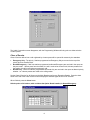
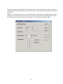
8. If "Yes" was selected in step 2, now with the modem power OFF, set the dip switches to the settings
shown below and then click on OK. For a description of "DIP" switch functions, refer to the table below.
Dip Switch
Number
SW1
SW2
SW3
SW4
SW5
SW6
SW7
SW8
Description
Override DTR
Verbal Result Codes
Suppress Result Codes
Echo Offline Commands
Auto Answer on Ring
Carrier Detect Normal
Load NVRAM Defaults on Power-up
Smart Mode
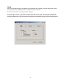
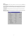
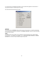
9. After modem setup is complete, the screen below appears verifying a successful setup.
MENU OPTIONS
PRINT
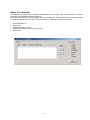
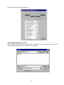
The print option allows the system to provide a hard-copy verification of how the system is programmed.
To print, the PC must be connected to a printer via the RS-232 serial printer port (DB9 connector).
21