1
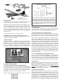
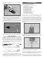
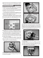
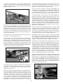
❑ 28) For the T-CLIPS, we need a finished distance from the back
edge of the motor mount to the motor’s thrust washer to end up
exactly 4-1/2”. This is important so the cowling will fit properly.
a) So what you need to do is to subtract the measurement
taken in the previous step (27) from 4-1/2”. The result is the distance you need to set the front of the firewall from the back edge
of the plywood motor mount box. (With the motor we are using in
these photos, the motor measurement is 2-1/2”. So 4-1/2” minus
2-1/2” = 2”. Your result may be different depending.)
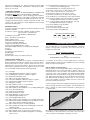
b) Next carefully measure and mark the distance determined
in the previous step from the back edge of the motor mount box
towards the front. Do this along side each of the adjustment slots
on both sides of the box (four marks total).
c) After you have all four slots marked, carefully align the front
face of the firewall to line up with the marks. Make sure you end
up with the firewall straight and square in the box. If it is not,
recheck your marks and adjust as necessary.
d) Tack glue the firewall in place. Recheck once more to make
sure that the front of the firewall is at the correct distance from the
back of the motor mount box. That distance plus the length of
your motor must equal 4-1/2”. When satisfied it is correct, glue
the firewall securely to the rest of the motor mount box.
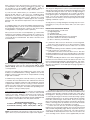
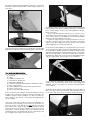
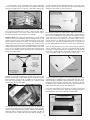
❑ 31) Trial fit the motor mount box onto the front of the fuselage,
inserting the tabs on the back of the box into the slots in the fuselage former. The box must fit tight against the former all the way
around with no gaps. If there is anything (like a gob of dried glue)
keeping the box from fitting up tight against the former, clean it up
now. When it fits properly, glue the motor mount box permanently
in place on the fuselage. We prefer epoxy glue for this.
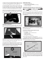
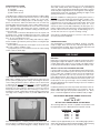
❑ 29) Mount your motor to the front of the firewall using the M4
Socket-Head Bolts, Lock Washers, and Blind Nuts provided.
a) On the front face of the firewall you will find four lines etched
into the plywood at 45 degrees. Use a sharp pencil and a straight
edge to extend these lines out to the edges of the firewall.
b) Set your motor in place on the firewall and carefully line up
the four motor mounting holes with the four 45 degree lines. Once
you are sure the motor is centered properly, mark the mounting
holes with a pencil. Remove the motor and drill out the mounting
holes with a 7/32" dia. drill bit.
c) Install the four M3 blind nuts in the holes, on the back side
of the firewall. Put a couple drops of medium CA glue on the
flanges of the blind nuts to secure them to the plywood, but be
careful not to get any of the glue in the threads.
d) Finally bolt your motor in place on the firewall.
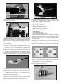
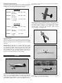
❑ 32) Install your Speed Controller (ESC)
a) Solder appropriate connectors (not supplied) to the battery
leads of your ESC.
b) Mount your ESC onto the plywood tray right behind the firewall, using one of the plastic cinch straps provided. Or if you prefer you can mount the ESC with double-sided servo tape or
Velcro® tape (neither of these are provided).
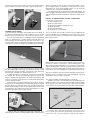
❑ 30) Locate the piece of balsa triangle stock provided. Measure,
cut and install pieces to reinforce the all corner joints inside the
motor mount box. Use Med or Thick CA glue for this job to ensure
a good bond and gap filling.
10