1
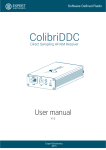
Operating instructions Series SX302 Alphanumeric large size displays with Ethernet interface BAL SX302 ETH EN 3.1 MAC address: : : : : : Site of the unit: Germany Siebert Industrieelektronik GmbH Siebertstrasse, D-66571 Eppelborn Phone +49 (0) 6806 980-0, Fax +49 (0) 6806 980-999 www.siebert.de, [email protected] France Siebert France Sarl 33 rue Poincaré, BP 90 334, F-57203 Sarreguemines Cédex Phone +33 (0) 3 87 98 63 68, Fax +33 (0) 3 87 98 63 94 www.siebert.fr, [email protected] Austria Siebert Österreich GmbH Karl-Eybl-Strasse 4, Postfach 19, A-2435 Ebergassing Phone +43 (0) 2234 795 25, Fax +43 (02234) 795 26 www.siebert-oesterreich.at, [email protected] Switzerland Siebert AG Bützbergstrasse 2, Postfach 91, CH-4912 Aarwangen Phone +41 (0) 62 922 18 70, Fax +41 (0) 62 922 33 37 www.siebert.ch, [email protected] © Siebert Industrieelektronik GmbH ® ® Siebert and LRD are registered trademarks of Siebert Industrieelektronik GmbH All other product names mentioned herein may be the trademarks or registered trademarks of their respective owners. Subject to change. – All rights reserved, including the rights of translation. No part of this document may in any form or by any means (print, photocopy, microfilm or any other process) be reproduced or by using electronic systems be processed, copied, or distributed without our written permission. 2 BAL SX302 ETH EN 3.1 Table of contents Chapter 1 Safety precautions Important information Safety Intended use Mounting and installation Grounding EMC measures Disposal Chapter 2 Unit description Model designation Unit construction Display technology Principle circuit diagram Display range Central Processing Unit Parameterization Ethernet interface Function inputs Auxiliary voltage Menu display Menu buttons Switching output Status indicators Ethernet LEDs Power supply Chapter 3 Control Activation commands Network parameters Socket connection Time-out Switching output Display test Demo operation mode Flashing Brightness Blanking ESC sequences Power-on reset Charater set Chapter 4 Parameterization Menu display Menu operation Menu item P Menu table Chapter 5 Configuration MAC Address Basic configuration Configuration via network Additional information Basic setting BAL SX302 ETH EN 3.1 3 Chapter 6 Technical data Unit properties Max. Power consumption Switching output Screw clips Housing colors Front frame Ambient conditions Chapter 7 Unit measurements and weights Units with one-side display Units with double-sided display 4 BAL SX302 ETH EN 3.1 Chapter 1 Safety precautions Important information Read these operating instructions before starting the unit. They provide you with important information on the use, safety and maintenance of the units. This helps you to protect yourself and prevent damage to the unit. Information intended to help you to avoid death, bodily harm or considerable damage to property are highlighted by the warning triangle shown here; it is imperative that this information be properly heeded. The operating instructions are intended for trained professional electricians familiar with the safety standards of electrical technology and industrial electronics. Store these operating instructions in an appropriate place. The manufacturer is not liable if the information in these operating instructions are not complied with. Safety Components inside the units are energized with electricity during operation. For this reason, mounting and maintenance work may only be performed by professionally-trained personnel while observing the corresponding safety regulations. The repair and replacement of components and modules may only be carried out by the manufacturer for safety reasons and due to the required compliance with the documented unit properties. The units do not have a power switch. They are operative as soon as the operating voltage is applied. Intended use The units are intended for use in industrial environments. They may only be operated within the limit values stipulated by the technical data. When configuring, installing, maintaining and testing the units, the safety and accident-prevention regulations relevant to use in each individual case must be complied with. Trouble-free, safe operation of the units requires proper transport, storage, installation, mounting and careful operation and maintenance of the units. Mounting and installation The attachment options for the units were conceived in such a way as to ensure safe, reliable mounting. The user must ensure that the attachment hardware, the unit carrier and the anchoring at the unit carrier are sufficient to securely support the unit under the given surrounding conditions. The units are to be mounted in such a way that they can be opened up while mounted. Sufficient space for the cables must be available in the unit near the cable infeed. Sufficient space is to be kept clear around the units to ensure air circulation and to prevent the build-up of heat resulting from use. The relevant information must be heeded in the case of units ventilated by other means. When the housing fasteners are opened, the front frame of the housing hinges out upward or downward (depending on the unit version) automatically. BAL SX302 ETH EN 3.1 5 Grounding All devices are equipped with a metal housing. They comply with safety class I and require a protective earth connection. The connecting cable for the operating voltage must contain a protective earth wire of a sufficient cross section (DIN VDE 0106 part 1, DIN VDE 0411 part 1). EMC measures The devices comply with the EU Directive 89/336/EEC (EMC Directive) and provide the required interference immunity. Observe the following when connecting the operating voltage and data cables: Use shielded data cables. The data and operating voltage cables must be laid separately. They may not be laid together with heavy-current cables or other interference-producing cables. The cable thickness must be properly assessed (DIN VDE 0100 Part 540). The cable lengths inside the units are to be kept as short as possible to prevent interference. This applies especially to unshielded operating voltage cables. Shielded cables are also to be kept short due to any interference which might be emitted by the shielding. Neither excessively long cables nor cable loops may be placed inside the units. The connection of the cable shielding to the functional ground (PE) must be as short and low-impedance as possible. It should be made directly to the mounting plate over a large area with a conductive clip: control data line terminals bare metal surface mouting plate conductive clamp Disposal 6 The cable shielding is to be connected at both cable ends. If equipotential bonding currents are expected due to the cable arrangement, electrical isolation is to be performed on one side. In this case, capacitive connection (approx. 0.1µF/600 V AC) of the shielding on the isolated side must occur. Units or unit parts which are no longer needed are to be disposed of in accordance with the regulations in effect in your country. BAL SX302 ETH EN 3.1 Chapter 2 Unit description Model designation The model designation of the units is: SX302-xx/xx/xx-xxx/xx-E0 x = The 'x's in the model designation indicate the size and design of the units (see Chapter 6). Unit construction The following figure shows model type S302-06/10/xx-xxx/xx-xx as example for the other model types. The front frame of the housing is locked with quick-action releases and can be hinged downward for opening the unit. The following figure shows the unit when open and reveals the modular construction of the units. All components, controls and connections are directly accessible. The display modules are found inside the housing front frame. The control computer and power supply unit are located in the lower housing section. Display technology BAL SX302 ETH EN 3.1 Depending on the type, the units are provided with a light-emitting LED or lightreflecting LRD®- display: SX302-xx/xx/0x-xxx/xx-xx: LED display SX302-xx/xx/2x-xxx/xx-xx LED display for outdoor application SX302-xx/xx/4x-xxx/xx-xx LRD® display 7 Principle circuit C8 C7 C6 C5 C4 C3 C2 C1 Central Processing Unit Ethernetconnection Power supply unit 10M RJ45 100M F2 Ethernet-Interface Display range F1 M P Function inputs/Auxiliary voltage NC NO CO Switching output L N PE Power supply Depending on the type, the units have the following displays: SX302-x1/xx/xx-xxx/xx-xx (1 digit): C1 SX302-x2/xx/xx-xxx/xx-xx (2 digits): C2…C1 SX302-x3/xx/xx-xxx/xx-xx (3 digits): C3…C1 SX302-x4/xx/xx-xxx/xx-xx (4 digits): C4…C1 SX302-x5/xx/xx-xxx/xx-xx (5 digits): C5…C1 SX302-x6/xx/xx-xxx/xx-xx (6 digits): C6…C1 SX302-x7/xx/xx-xxx/xx-xx (7 digits): C7…C1 SX302-x8/xx/xx-xxx/xx-xx (8 digits): C8…C1 Devices with double-sided display (SX302-xx/xx/xx-2xx/xx-xx) show the same information on the front and rear side. Central Processing Unit 8 The following figure shows the Central Processing Unit: BAL SX302 ETH EN 3.1 Parameterization The parameterization of the unit is done by means of a menu in the menu display (see chapter 4). Ethernet interface The Ethernet interface serves for activation of the devices (see chapter 4.) It is a standard-RJ45 socket and has the following specifications: Data rate: 10/100 Mbps, Automatic detection Galvanic separation: 1,5 kV Supported protocols: ICMP, ARP, IP, TCP, UDP, DHCP, Telnet and HTTP Operation modes: TCP Server, TCP Client and UDP The units are set-up as TCP server by default. The data is transmitted to port 8000 via a socket connection (factory settings). Other ports between 2000 and 9999 can be set via the menu (see chapter 4). Configuration: The basic configuration can be set up without external aids via the menu (see chapter 4). Further settings can be done via Web Browser or Telnet console (see chapter 5). The Telnet and HTTP protocols are used exclusively for configuration, not for data transmission. Function inputs The function inputs allow, independently of commands via the Ethernet interface, a reduction the brightness and the flashing of the display (see chapter 3). It is located on the screw type terminal of the control computer. The function inputs are PLC-compatible and are designed for the following signal voltages: Signal voltage: L = -3.5...+5 V (open input = L) H = +18...30 V (active H), M = reference potential Auxiliary voltage The units supply terminal P with an auxiliary voltage galvanically isolated from the operating voltage, which can serve as H signal (24 V ± 25%, max. 50 mA, M = reference potential). Menu display The menu display see chapter 4). represents a menu for unit parameterization ( During normal operation On nE appears in the menu display as soon as data arrive at the Ethernet interface. Menu buttons The menu can be operated by means of the menu buttons (see chapter 4). Switching output The devices dispose of a switching output (relay) with potential-free change-over contact (NC, NO, CO). BAL SX302 ETH EN 3.1 9 Status indicators The status indicators (LEDs) of the central processing unit have the following function: READY STAT: On = Ready for data transmission via Ethernet Off = Address conflict on the Ethernet DHCP: On = Ready for data transmission via Ethernet Off = No DHCP server found DATA Data are received OUT Switching output is active Ethernet-LEDs The data transmission rate is detected automatically and displayed via the 100M and 10M Ethernet LEDs. A permanently lit LED signals a connection having the indicated speed. Flickering means additional data exchange. Power supply The power supply of the units is connected to the terminals L, N and PE. They are located on the power supply unit. In devices for a power supply of 24 V (S302-xx/xx/xx-xxx/xB-xx), the terminals are designated with +, – and PE. Chapter 3 Control Activation commands All commands and data telegrams require a telegram ending (*) with the characters CR, LF or CR/LF. Network parameters The network parameters can be set in the menu and no external aids are necessary. Once this has been done, the unit can be accessed via the network. Further settings can then be made via the network (see chapter 5). In the IP menu item, static address assignment or DHCP must be selected. In the I1...I4 menu items, the four bytes of the IP address are set, if static address assignment has been selected. In the S1...S4 menu items, the four address bytes of the Subnet Mask are set, if static address assignment has been selected. In the G1...G4 menu items, the four bytes of the standard gateway address are set, if static address assignment has been selected. Upon resetting the factory settings (Default) in menu item U, DHCP will be activated. After switching to static address assignment, the following addresses are set infactory by default: 10 IP-Address192.168.127.254 Subnet Mask 255.255.255.000 Standard-Gateway 192.168.127.001 BAL SX302 ETH EN 3.1 Socket connection The units are set up as TCP server by default. The data is transmitted to port 8000 via a socket connection (factory settings). Other ports between 2000 and 9999 can be set in menu item P (see chapter 4). In menu item P, the decimal points of the port number flash one after the other. The digit with the decimal point flashing can be set to the value requested by means of the menu key [Q]. Time-out In menu item t, it is possible to set whether a time-out occurs, and if so, after what time. Time-out means that a minus sign appears on the display if the unit has not received a data telegram after a defined time. Switching output The devices dispose of a switching output (relay) with potential-free change-over contact (NC, NO, CO). When setting OFF in menu item r, the switching output can be activated with the following command: Activate switching contact: $Q@1 Deactivate switching contact: $Q@0 When setting 1, 2 or 4 in menu item r, the command $Q@1 causes a wiping pulse at the switching output with a duration of 1, 2 or 4 seconds. When setting A1, A2 or A4 in menu item r, the switching output automatically gives a wiping pulse with a duration of 1, 2 or 4 seconds with every telegram ending. The relay switches after realized telegram ending. The wiping function is suitable, for example, for activating optical and acoustic signal transmitters. The status indicator OUT of the control computer is lighted with active switching output. Display test In menu item F, you can set whether a display test is to be performed after the operating voltage is applied. The display test can be also activated via the serial interface with the following command: Display test on : $T1 Display test off $T0 The display test has priority over blanking and flashing. Demo operation mode If the setting PlAy is selected in menu item F, random characters are displayed. In this case, it is impossible to activate the unit. Flashing Flashing of the display can be activated with the following command: Flashing on: $F1 Flashing off: $F0 If$F1 is sent in the data telegram, the succeeding digits will flash until the end of the data telegram or until$F0 is sent in the data telegram. Flashing of the display can also be activated by application of the H signal to functional input F1 (priority compared to the commands). For units provided with an LRD® display flashing is not possible. BAL SX302 ETH EN 3.1 11 Brightness The brightness of the display can be reduced with the following command: Normal brightness: $L0 Reduced brightness: $L1 The brightness of the display can also be reduced with an H signal applied to functional input F2 (priority compared to the commands). For units provided with an LRD® display brightness reduction is not possible. Blanking The display can be blanked with the following command (priority compared to flashing): Blanking on: $B1 Blanking off: $B0 ESC sequences The character <ESC> (1Bh) can be used in the command instead of the § character, e.g. <ESC>L1 instead $L1. Power-on reset After power-on, minus signs are displayed to signalize that the unit is ready for operation. If a display test has been preselected in menu item F, it will run beforehand. Charater set 0 1 2 3 4 5 6 7 8 9 A B C D E F B R b r E Æ O C S c s A O U │ D T d t A O N E U e u A O F V f v A U G W g w H X h x E Y I Y i y K L M N O k l m n o I I A A O J Z j z E U ! 2 3 4 5 P 6 7 p 8 9 A B E A A Q a q U Æ I U C D E F 12 BAL SX302 ETH EN 3.1 Chapter 4 Parameterization Menu The parameterization of the devices is carried out in a menu of the menu display. During normal operation On nE appears in the menu display as soon as data arrive at the Ethernet interface. Menu operation To reach the menu, press both menu buttons simultaneously (approx. 1 sec.) until an audible signal is heard and menu item 01 appears in the menu display. Now, you can navigate in the menu as follows: Next menu item: Page menu items forward: Previous menu item: Page menu items backward: Shortly press key [R] Press key [R] long Double click on key [R] Double click on [R] and keep it pressed Next setting Page settings forward: Previous setting Page setting backward: Shortly press key [Q] Press key [Q] long Double click on key [Q] Double click on [Q] and keep it pressed The menu ends in menu item Uwith the button [R]. The settings made are either saved (set), not saved (escape) or the factory settings are reset, depending on the setting selected in menu item U. Canceling the menu without saving the settings made is possible by pressing both menu buttons longer (approx. 1 sec.) or will occur automatically if 60 seconds pass without a menu button being pressed. Once the menu is closed, the unit behaves in the same manner as when the operating voltage was applied. In the menu mode the character appears in the main display. Control of the display is not possible in menu mode. Menu item P In menu item P, the decimal points of the port number flash one after the other. The digit with the decimal point flashing can be set to the value requested by means of the menu key [Q]. Menu table The menu items are displayed in the following menu table. The factory settings are marked with an *. Individual menu items or settings can be suppressed in another menu item, depending on the unit version or setting. BAL SX302 ETH EN 3.1 13 Menu item IP IP-Address Settings Static DHCP* I1 IP-Address Byte 1 (xxx.- . . - -) 192.168.127.254* 0 L 255 192* L IP-Address Byte 2 (- - -.xxx.- . - -) 0 L 255 168* L IP-Address Byte 3 (- - -.- - -.xxx.- - -) 0 L 255 127* L IP-Address Byte 4 (- - -.- . - -.xxx) 1 L 254 254* L Subnet Mask Byte 1 (xxx.- . . - -) 255.255.255.0* 0 L 255 255* S L Subnet Mask Byte 2 (- - -.xxx.- . - -) 0 L 255 255* 0 L 255 255* 1 L 255 000* Standard-Gateway Byte 1 (xxx.- . . - -) 192.168.127.001* 0 L 255 192* Standard-Gateway Byte 2 (- - -.xxx.- . - -) 0 L 255 168* 0 L 255 127* 1 L 254 001* I2 I3 I4 S1 S2 S3 S4 G1 G2 G3 G4 P 14 Subnet Mask Byte 3 (- - -.- - -.xxx.- - -) Subnet Mask Byte 4 (- - -.- . - -.xxx) Standard-Gateway Byte 3 (- - -.- - -.xxx.- - -) Standard-Gateway Byte 4 (- - -.- . - -.xxx) Port Menu display P Stat P DHCP S S L S S L S S L S G L G G L G G L G 2000…8000*…9999 G L G P nnnn BAL SX302 ETH EN 3.1 Menu item R Switching output BAL SX302 ETH EN 3.1 Settings No wiping pulse* Wiping pulse 1 sec Wiping pulse 2 sec Wiping pulse 4 sec Automatic wiping pulse 1 sec Automatic wiping pulse 2 sec Automatic wiping pulse 4 sec Menu display r r r r r r r OFF A A A T Time-out No time-out * Time-out after 2 s Time-out after 4 s Time-out after 8 s Time-out after 16 s Time-out after 32 s Time-out after 64 s Time-out after 128 s t t t t t t t t F Display test No display test at power-on * Display test at power-on Demo operation mode F F F Play U Saving Saving parameters* (Set) Not saving parameters (Escape) Resetting to the default settings (Default) U U U set ESC deF 15 Chapter 5 Configuration MAC address The MAC address of the unit is to be found on the Ethernet coupling of the control processor (see label). It is possibly needed for commissioning and should be written down on page 2 of this operating manual before the unit is mounted on a hardly accessible location. Basic configuration The basic configuration can be set up without external aids via the menu (see chapter 4). To integrate the unit in the network, either DHCP must be activated, or the static IP address, the relevant Subnet Mask and, if necessary, the IP address of the standard gateway must be set. These values are assigned by the system administrator and should be known before putting the unit into operation. Configuration via network As soon as the units can accessed via TCP/IP, additional configuration can take place via Telnet and HTTP. Access can be password-protected or can be deactivated, to prevent unauthorized operations. As-delivered and after setting the default in menu item U, access is enabled. Additional information The configuration dialogs are self-explanatory. For detailed information, please refer to the documentation of the Ethernet coupling (Moxa NE4100T type). For further information and PC tools, please go to www.moxa.com. Basic setting Via Telnet and HTTP the gateway can inadvertently be parameterized so that it is no longer accessible via the network. In this case the gateway can be rest in a defined status via menu and selection of default in menu item U (see chapter 4) and after resetting of the network parameters it can be accessed via network again. 16 BAL SX302 ETH EN 3.1 Chapter 6 Technical data Unit properties The model designation is structured as follows: SX302 1 digit 2 digits 3 digits 4 digits 5 digits 6 digits 7 digits 8 digits – / : 0 0 0 0 0 0 0 0 : 1 2 3 4 5 6 7 8 Character height of 50 mm Character height of 100 mm / : : : : : : : : : : 0 1 LED ® LRD : : : : : : : : : : 5 0 – : : : : : : : : : : : : : 0 4 Color of the characters red Color of the characters green Color of the characters white : : : : : : : : : : : : : : : : R G W Display readable on one side Display readable on both sides Steel sheet housing, coated Steel sheet housing, bilayer painting Steel sheet housing V2A, coated Steel sheet housing V2A, brushed Steel sheet housing V4A, brushed Protection type IP54 Protection type IP65 Protection type IP54 climate adjustment Protection type IP54 climate adjustment and heating Wall mounting, cable entry point from the bottom Wall mounting, cable entry point from the top Hanging installation, cable entry point from the bottom Hanging installation, cable entry point from the top Wall and hanging installation, cable entry point from the bottom Wall and hanging installation, cable entry point from the top Power supply 230 V AC ±15 %, 50 Hz Power supply 24 V DC ±15 % Power supply 115 V AC ±15 %, 60 Hz BAL SX302 ETH EN 3.1 / : : : : : : : : : : : : : : : : : : : : 1 2 : : : : : : : : : : : : : : : : : : : : : : : 0 1 2 3 5 : : : : : : : : : : : : : : : : : : : : : : : : : : : : : 0 1 2 4 – : : : : : : : : : : : : : : : : : : : : : : : : : : : : : : : : : : 0 1 2 3 4 5 M 0 : : : : : : : : : : : : : : : : : : : : : : : : : : : : : : : : : : : : : : : : : A B C 17 Max. power consumption Units with one-side display Units with double-sided display 1 digit SX302-01/10/0x-1xx/xx-xx SX302-01/10/4x-1xx/xx-xx approx. 12 VA approx. 50 VA 1 digit SX302-01/10/0x-2xx/xx-xx SX302-01/10/4x-2xx/xx-xx approx. 16 VA approx. 91 VA 2 digits SX302-02/05/0x-1xx/xx-xx SX302-02/10/0x-1xx/xx-xx SX302-02/10/4x-1xx/xx-xx approx. 12 VA approx. 15 VA approx. 50 VA 2 digits SX302-02/05/0x-2xx/xx-xx SX302-02/10/0x-2xx/xx-xx SX302-02/10/4x-2xx/xx-xx approx. 15 VA approx. 21 VA approx. 91 VA 3 digits SX302-03/05/0x-1xx/xx-xx SX302-03/10/0x-1xx/xx-xx SX302-03/10/4x-1xx/xx-xx approx. 13 VA approx. 17 VA approx. 50 VA 3 digits SX302-03/05/0x-2xx/xx-xx SX302-03/10/0x-2xx/xx-xx SX302-03/10/4x-2xx/xx-xx approx. 17 VA approx. 26 VA approx. 91 VA 4 digits SX302-04/05/0x-1xx/xx-xx SX302-04/10/0x-1xx/xx-xx SX302-04/10/4x-1xx/xx-xx approx. 14 VA approx. 21 VA approx. 50 VA 4 digits SX302-04/05/0x-2xx/xx-xx SX302-04/10/0x-2xx/xx-xx SX302-04/10/4x-2xx/xx-xx approx. 19 VA approx. 33 VA approx. 91 VA 5 digits SX302-05/05/0x-1xx/xx-xx SX302-05/10/0x-1xx/xx-xx SX302-05/10/4x-1xx/xx-xx approx. 15 VA approx. 23 VA approx. 50 VA 5 digits SX302-05/05/0x-2xx/xx-xx SX302-05/10/0x-2xx/xx-xx SX302-05/10/4x-2xx/xx-xx approx. 21 VA approx. 38 VA approx. 91 VA 6 digits SX302-06/05/0x-1xx/xx-xx SX302-06/10/0x-1xx/xx-xx SX302-06/10/4x-1xx/xx-xx approx. 16 VA approx. 26 VA approx. 50 VA 6 digits SX302-06/05/0x-2xx/xx-xx SX302-06/10/0x-2xx/xx-xx SX302-06/10/4x-2xx/xx-xx approx. 23 VA approx. 43 VA approx. 91 VA 7 digits SX302-07/05/0x-1xx/xx-xx SX302-07/10/0x-1xx/xx-xx SX302-07/10/4x-1xx/xx-xx approx. 17 VA approx. 30 VA approx. 50 VA 7 digits SX302-07/05/0x-2xx/xx-xx SX302-07/10/0x-2xx/xx-xx SX302-07/10/4x-2xx/xx-xx approx. 25 VA approx. 51 VA approx. 91 VA 8 digits SX302-08/05/0x-1xx/xx-xx SX302-08/10/0x-1xx/xx-xx SX302-08/10/4x-1xx/xx-xx approx. 18 VA approx. 32 VA approx. 50 VA 8 digits SX302-08/05/0x-2xx/xx-xx SX302-08/10/0x-2xx/xx-xx SX302-08/10/4x-2xx/xx-xx approx. 27 VA approx. 55 VA approx. 91 VA For units with built-in heating, the values for power consumption specified in the table increase by approx. 10 – 100 VA (exact values on request), depending on the unit size). Switching output Maximum switching voltage Maximum switching current 30 V AC/DC 500 mA (resistive load) Screw type terminal Control computer Power supply Capacity of terminals 0,14…1,5 mm2 Capacity of terminals 0,2…4 mm2 Housing colors Front pane Front pane RAL 5002 ultramarine RAL 7035 light grey Front frame SX302-xx/xx/xR-xxx/xx-xx SX302-xx/xx/xG-xxx/xx-xx plastic, tinted red, non-reflective plastic, tinted green, non-reflective Ambient conditions Operating temperature Storage temperature Relative Feuchte 0…55 °C -30…85 °C max. 95 % (non-condensing) 18 BAL SX302 ETH EN 3.1 Chapter 7 Unit measurements and weights Units with one-side display The following figure shows unit version S302-04/10/4x-1xx/xx-xx, representing the other unit versions listed in the following table. BAL SX302 ETH EN 3.1 1 digit SX302-01/10/xx-1xx/xx-xx A 330 mm B 245 mm C 145 mm D 32 mm ø 7 mm Weight approx. 7 kg 2 digits SX302-02/05/xx-1xx/xx-xx SX302-02/10/xx-1xx/xx-xx 300 mm 330 mm 185 mm 245 mm 110 mm 145 mm 32 mm 32 mm 7 mm 7 mm approx. 5 kg approx. 7 kg 3 digits SX302-03/05/xx-1xx/xx-xx SX302-03/10/xx-1xx/xx-xx 300 mm 480 mm 185 mm 245 mm 110 mm 145 mm 32 mm 32 mm 7 mm 7 mm approx. 5 kg approx. 9 kg 4 digits SX302-04/05/xx-1xx/xx-xx SX302-04/10/xx-1xx/xx-xx 300 mm 480 mm 185 mm 245 mm 110 mm 145 mm 32 mm 32 mm 7 mm 7 mm approx. 5 kg approx. 9 kg 5 digits SX302-05/05/xx-1xx/xx-xx SX302-05/10/xx-1xx/xx-xx 400 mm 680 mm 185 mm 245 mm 110 mm 145 mm 32 mm 32 mm 7 mm 7 mm approx. 6 kg approx. 12 kg 6 digits SX302-06/05/xx-1xx/xx-xx SX302-06/10/xx-1xx/xx-xx 400 mm 680 mm 185 mm 245 mm 110 mm 145 mm 32 mm 32 mm 7 mm 7 mm approx. 6 kg approx. 12 kg 7 digits SX302-07/05/xx-1xx/xx-xx SX302-07/10/xx-1xx/xx-xx 510 mm 870 mm 185 mm 245 mm 110 mm 145 mm 32 mm 32 mm 7 mm 7 mm approx. 7 kg approx. 14 kg 8 digits SX302-08/05/xx-1xx/xx-xx SX302-08/10/xx-1xx/xx-xx 510 mm 870 mm 185 mm 245 mm 110 mm 145 mm 32 mm 32 mm 7 mm 7 mm approx. 7 kg approx. 14 kg 19 Units with double-sided display The following figure shows unit version S302-04/10/4x-2xx/xx-xx, representing the other unit versions listed in the following table. Units with character height of 50 mm (SX302-xx/06/xx2xx/xx-xx) are provided with 2 eyes instead of 4. 20 1 digit SX302-01/10/xx-2xx/xx-xx A 330 mm B 245 mm C 240 mm Weight approx. 11 kg 2 digits SX302-02/05/xx-2xx/xx-xx SX302-02/10/xx-2xx/xx-xx 300 mm 330 mm 185 mm 245 mm 150 mm 240 mm approx. 9 kg approx. 11 kg 3 digits SX302-03/05/xx-2xx/xx-xx SX302-03/10/xx-2xx/xx-xx 300 mm 480 mm 185 mm 245 mm 150 mm 240 mm approx. 9 kg approx. 15 kg 4 digits SX302-04/05/xx-2xx/xx-xx SX302-04/10/xx-2xx/xx-xx 300 mm 480 mm 185 mm 245 mm 150 mm 240 mm approx. 9 kg approx. 15 kg 5 digits SX302-05/05/xx-2xx/xx-xx SX302-05/10/xx-2xx/xx-xx 400 mm 680 mm 185 mm 245 mm 150 mm 240 mm approx. 9 kg approx. 19 kg 6 digits SX302-06/05/xx-2xx/xx-xx SX302-06/10/xx-2xx/xx-xx 400 mm 680 mm 185 mm 245 mm 150 mm 240 mm approx. 9 kg approx. 19 kg 7 digits SX302-07/05/xx-2xx/xx-xx SX302-07/10/xx-2xx/xx-xx 510 mm 870 mm 185 mm 245 mm 150 mm 240 mm approx. 11 kg approx. 23 kg 8 digits SX302-08/05/xx-2xx/xx-xx SX302-08/10/xx-2xx/xx-xx 510 mm 870 mm 185 mm 245 mm 150 mm 240 mm approx. 11 kg approx. 23 kg BAL SX302 ETH EN 3.1