1
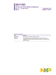
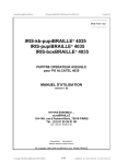
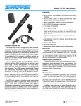
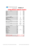
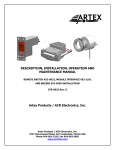
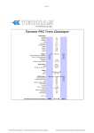
CIRRUS
AIRPLANE MAINTENANCE MANUAL
MODEL SR22
EMERGENCY
1. DESCRIPTION
A. Emergency Locator Transmitter (ELT)
This airplane is equipped with a self-contained ELT. The ELT transmitter is installed immediately
behind the aft cabin bulkhead. The ELT is mounted slightly to the right of the airplane centerline. The
transmitter and antenna are accessible through an access panel at the base of the baggage compartment bulkhead. Two different ELT models are available on the airplane. The standard ACK E-01 ELT
and the optional Artex ME406 ELT.
Serials 0002 & subs w/ ACK E-01 ELT: The transmitter unit is mounted longitudinally in the airplane in
order to detect deceleration greater than 3.5 feet per second. If rapid deceleration is detected, the
transmitter will repeatedly transmit VHF band audio sweeps at 121.5 Mhz and 243.0 Mhz approximately 0.5 seconds apart. The transmitter is automatically activated upon sensing a change of velocity
along its longitudinal axis, exceeding 3 to 5 feet per second. The transmitter can be removed from the
airplane and used as a personal locating device if it is necessary to leave the airplane after an accident.
The main transmitter control switch is labeled ON-OFF-ARMED. The transmitter is in the armed position for normal operations. Eight dated “D” cell alkaline batteries contained within the transmitter unit
provide power to the transmitter. Replace all ELT batteries at the same time and with the same expiration date stamp. The expiration date of the batteries must be indicated on the outside of the ELT battery case and recorded in the aircraft logs.
The ELT Remote Switch and Control Panel Indicator (RCPI) is located below the circuit breakers on
the circuit breaker panel. The RCPI provides test and monitoring functions for the transmitter. The
panel contains a button labeled ON, a button labeled RESET, and a red LED indicator light. The ON
button is used to test the unit in accordance with the manufacturer’s approved Instructions For Continued Airworthiness and/or other service instructions. The RESET button can be used to cancel an inadvertent transmission. The red light flashes when the ELT is transmitting. A Duracell PX28L or Kodak
K28L 6-volt lithium battery mounted in the panel powers the LED.
WARNING:
The ACK E-01 ELT is designed to use only Duracell MN1300 or PC 1300 alkaline
batteries which are dated by the manufacturer. This ELT does not meet the
requirements of TSO-91a or 14 CFR 91.207 if used with any other type of battery.
ELT and RCPI batteries must be inspected in accordance with the requirements of
the replacement schedule in Chapter 5. The ELT and RCPI batteries must be
replaced upon reaching the date stamped on the batteries or whenever the batteries have been in use for one cumulative hour.
Refer to the manufacturer’s approved Instructions For Continued Airworthiness and/or other service
instructions.
Serials 1863 & subs w/ Artex ME406 ELT: The transmitter unit is mounted longitudinally in the airplane
in order to detect deceleration greater than 4.5 ± 0.5 feet per second. If rapid deceleration is detected,
the transmitter will repeatedly transmit VHF band audio sweeps at 121.5 Mhz until battery power is
gone. In addition, for the first 24 hours of operation, a 406 MHz signal is transmitted at 50-second intervals. This transmission lasts 440 ms and contains identification data programmed into the beacon and
is received by Cospas-Sarsat satellites. The transmitted data is referenced in a database (maintained
by the national authority responsible for ELT registration) and used to identify the beacon and owner.
The transmitter is automatically activated upon sensing a change of velocity along its longitudinal axis,
exceeding 4 to 5 feet per second. The transmitter can be removed from the airplane and used as a
personal locating device if it is necessary to leave the airplane after an accident.
EFFECTIVITY:
All
25-60
Page 1
15 Apr 2007
CIRRUS
AIRPLANE MAINTENANCE MANUAL
MODEL SR22
The main transmitter control switch is labeled ON-ARM. The transmitter is in the armed position for
normal operations. A red LED indicator light flashes when the ELT is transmitting. A battery pack consisting of two “D” cell lithium batteries mounts to a cover assembly within the transmitter to provide
power to the transmitter. The expiration date of the batteries must be indicated on the outside of the
ELT battery case and recorded in the aircraft logs.
The ELT Remote Switch and Control Panel Indicator (RCPI) is located below the circuit breakers on
the circuit breaker panel. The RCPI provides test and monitoring functions for the transmitter. The
panel contains a switch labeled ON-ARM, and a red LED indicator light. The ON switch is used to test
the unit in accordance with the manufacturer's approved service instructions. The red LED indicator
light flashes when the ELT is transmitting. Power to the LED is supplied by either the clock bus on the
MCU (Serials 1863 thru 2083) or by a 6V lithium battery in the RCPI (Serials 2084 & subs).
A warning buzzer is mounted to the transmitter mounting tray. When the ELT is activated, the buzzer
“beeps” periodically. This buzzer operates in tandem with the ELT panel indicator and would serve as a
redundant indicator. Power to the buzzer is supplied by the ELT batteries.
After setting transmitter switch to ARM position, the ELT automatically enters a self-test mode. The
self-test transmits a 406 MHz test coded pulse that monitors certain system functions before shutting
off. The test pulse is ignored by any satellite that receives the signal, but the ELT uses this pulse to
check output power and frequency. Other parameters of the ELT are checked and a set of error codes
is generated if a problem is found. The error codes are indicated by a series of pulses on the transmitter LED, remote control panel indicator LED, and alert buzzer. One pulse indicates that the system is
operational and no error conditions were found. For a list of error codes, see Troubleshooting. (Refer to
25-60)
WARNING:
ELT and RCPI batteries must be inspected in accordance with the requirements of
the replacement schedule in Chapter 5. The ELT and RCPI batteries must be
replaced upon reaching the date stamped on the batteries, after an inadvertent
activation of unknown duration, or whenever the batteries have been in use for
one cumulative hour.
Refer to the manufacturer’s approved Instructions For Continued Airworthiness and/or other service
instructions.
25-60
Page 2
15 Apr 2007
EFFECTIVITY:
All
CIRRUS
AIRPLANE MAINTENANCE MANUAL
MODEL SR22
2. TROUBLESHOOTING
Serials 1863 & subs w/ Artex ME406 ELT:
Trouble
Self test indicates 3 flash error.
Self test indicates 4 flash error.
Probable Cause
Remedy
Open or shorted antenna cable.
Verify antenna cable is connected
and in good condition. Perform
continuity check of center conductor and shield. Check cable for
shorts or intermittent connection.
Faulty antenna.
Using a voltage standing wave
ratio (VSWR) meter, check
antenna for opens, shorts, or
resistive ground plane connection.
Verify battery voltage. Replace
Low power detected. Occurs if
battery if low voltage or if 7 Flash
output power is below about 33
dBm (2 watts) for the 406 signal or error is also present.
17 dBm (50 mW) for the 121.5
MHz signal.
406 signal is off frequency.
Verify 406 MHz frequency. If bad,
the ELT must be sent back for
repair or replacement.
Self test indicates 5 flash error.
ELT has not been programmed.
If possible, read ELT 406 MHz signal to verify programming.
Self test indicates 6 flash error.
G-switch jumper wire not installed
between pins 5 and 12 of D-sub
connector. ELT will not activate
during a crash.
Verify less than 1 ohm of resistance between pins 5 and 12 of Dsub connector. If necessary, install
G-switch jumper wire.
Self test indicates 7 flash error.
Accumulated operation time on
battery has exceeded 1 hour.
Replace battery.
Battery circuit damaged.
Inspect battery circuit.
Remote switch LED always illumi- Wiring error.
Verify wiring.
nated.
Frayed wires shorting out pins on Verify integrity of all crimp or solback of remote switch.
der connections on harness.
EFFECTIVITY:
All
25-60
Page 3
15 Apr 2007
CIRRUS
AIRPLANE MAINTENANCE MANUAL
MODEL SR22
3. MAINTENANCE PRACTICES
A. Emergency Locator Transmitter - Serials 0002 & subs w/ ACK E-01 ELT (See Figure 25-601)
(1)
(2)
Removal - ELT
(a) Remove access panel CB06. (Refer to 06-00)
(b) Set transmitter control switch to OFF position.
(c)
Disconnect remote control panel indicator cable from transmitter.
(d) Disconnect antenna cable from transmitter.
(e) Remove portable antenna from transmitter.
(f)
Open quick release straps securing transmitter to mounting tray. Remove transmitter from
airplane.
Installation - ELT
WARNING:
(a)
Position transmitter to mounting tray with printed arrow on battery case pointing in direction of flight.
Note:
(3)
ELT must be installed with printed arrow on battery case pointing in the
direction of flight.
The quick release straps which secure the transmitter to the mounting tray
are slightly different sizes. The strap which fits around front of transmitter is
marked FRONT. The strap which fits around battery end of transmitter is
marked BATTERY.
(b) Close quick release straps securing transmitter to mounting tray.
(c)
Position portable antenna to transmitter and secure.
(d) Connect antenna cable to transmitter.
(e) Connect remote control panel indicator cable to transmitter.
(f)
Perform Operational Test - ELT. (Refer to 25-60)
(g) Install access panel CB06. (Refer to 06-00)
Operational Test - ELT
Note:
Regulations require that transmitter tests only be done during the first 5 minutes of
each hour and must not last for more than 3 audio sweeps (1.5 seconds). If you
are at a location where there is an FAA control tower or other monitoring facility,
notify the facility before beginning the tests. Never activate the ELT while airborne
for any reason.
A low quality AM broadcast receiver should be used to determine if energy is
being transmitted from the antenna. When the antenna of the radio (tuning dial on
any setting) is held about 6 inches from the activated ELT antenna, the ELT aural
tone will be heard on the AM broadcast receiver. This is not a measured check,
but it does provide confidence that the antenna is radiating sufficient power to aid
search and rescue. The aircraft’s VHF receiver, tuned to 121.5 MHz, may also be
used. This receiver, however, is more sensitive and could pick up a weak signal
even if the radiating ELT’s antenna is disconnected. Thus it does not check the
integrity of the ELT system or provide the same level of confidence as does an AM
radio.
(a)
(b)
(c)
25-60
Page 4
15 Apr 2007
Remove access panel CB06. (Refer to 06-00)
Monitor 121.5 Mhz using aircraft COM receiver or portable hand-held receiver.
Turn receiver squelch control all the way down or to OFF position.
EFFECTIVITY:
Serials 0002 & subs w/ ACK E-01 ELT
CIRRUS
(4)
AIRPLANE MAINTENANCE MANUAL
MODEL SR22
(d) Set transmitter control switch to ON position.
(e) Verify audio sweep tone can be heard on COM receiver.
(f)
Set transmitter control switch to ARMED position.
(g) Press ON button on remote control panel indicator.
(h) Verify LED flashes and is readily visible from pilots operating position.
(i)
Verify audio sweep tone can be heard on COM receiver.
(j)
Push RESET button on remote control panel indicator.
(k)
Verify LED stops flashing and audio sweep tone stops transmitting.
(l)
Install access panel CB06. (Refer to 06-00)
Inspection/Check - ELT
Note:
(a)
(b)
(c)
(d)
Perform Inspection/Check in accordance with 14 CFR 91.207.
Remove ELT. (Refer to 25-60)
Visually inspect mounting tray, fasteners, and mechanical assemblies for security.
Visually inspect antenna cable and RCPI cable for cuts, abrasions, or signs of wear.
Visually inspect all cable connectors and mating plugs for signs of corrosion.
Note:
(e)
(f)
(g)
(h)
Pay special attention to antenna cable center conductor pins which are
prone to retracting into connector housing.
Visually inspect and confirm proper seating of all connector pins.
Check transmitter batteries for expiration date and corrosion. Replace if necessary. (Refer
to 25-60)
Check RCPI battery for expiration date and corrosion. Replace if necessary. (Refer to 2560)
Verify operation of G-switch.
Note:
Regulations require that transmitter tests only be done during the first 5
minutes of each hour and must not last for more than 3 audio sweeps (1.5
seconds). If you are at a location where there is an FAA control tower or
other monitoring facility, notify the facility before beginning the tests.
1
2
3
(i)
Set transmitter control switch to ARMED position.
Hold transmitter with printed arrow on battery case pointing forward.
Activate ELT with a rapid forward throwing motion coupled by a rapid reversing
motion.
4
Verify transmitter activation by monitoring 121.5 Mhz with aircraft COM receiver or
portable hand-held receiver.
5
Set transmitter control switch to OFF position.
Install ELT. (Refer to 25-60)
EFFECTIVITY:
Serials 0002 & subs w/ ACK E-01 ELT
25-60
Page 5
15 Apr 2007
CIRRUS
AIRPLANE MAINTENANCE MANUAL
MODEL SR22
CIRCUIT BREAKER
PANEL
(REF)
12
8
9
11
4
5
ELT MOUNTING
TRAY
(REF)
2
10
6
3
7
7
1
4
LEGEND
1. ELT Portable Antenna
2. Antenna Cable
3. RJ-11 Coupler
4. RCPI Connecting Cable
5. ELT
6 ELT Antenna
7. Adel Clamp
8. Washer
9. Nut
10. Cable Tie
11. Remote Control
Panel Indicator (RCPI)
12. Screw
8
9
2
Serials 0002 thru 0820.
Figure 25-601
ELT Installation - Serials 0002 thru 0820 (Sheet 1 of 2)
25-60
Page 6
15 Apr 2007
EFFECTIVITY:
Serials 0002 thru 0820
SR22_MM25_1419C
CIRRUS
AIRPLANE MAINTENANCE MANUAL
CIRCUIT BREAKER
PANEL
(REF)
8
MODEL SR22
9
11
12
5
ELT MOUNTING
TRAY
(REF)
4
2
3
10
6
7
1
8
9
2
LEGEND
1. ELT Portable Antenna
2. Antenna Cable
3. RJ-11 Coupler
4. RCPI Connecting Cable
5. ELT
6 ELT Antenna
7. Adel Clamp
8. Washer
9. Nut
10. Cable Tie
11. Remote Control
Panel Indicator (RCPI)
12. Screw
SR22_MM25_1920A
Figure 25-601
ELT Installation - Serials 0821 & subs w/ ACK E-01 ELT (Sheet 2 of 2)
EFFECTIVITY:
Serials 0821 & subs w/ ACK E-01 ELT
25-60
Page 7
15 Apr 2007
CIRRUS
AIRPLANE MAINTENANCE MANUAL
MODEL SR22
B. Emergency Locator Transmitter - Serials 1863 & subs w/ Artex ME406 ELT (See Figure 25-602)
(1)
(2)
(3)
Removal - ELT
(a) Remove access panel CB06. (Refer to 06-00)
(b) Disconnect remote control panel indicator cable from transmitter.
(c)
Disconnect antenna cable from transmitter.
(d) Loosen strap securing transmitter to mounting tray. Remove transmitter from airplane.
Installation - ELT
(a) Position transmitter to mounting tray and secure with strap.
(b) Connect antenna cable to transmitter.
(c)
Connect remote control panel indicator cable to transmitter.
(d) Perform Operational Test - ELT. (Refer to 25-60)
(e) Install access panel CB06. (Refer to 06-00)
Operational Test - ELT
Note:
Regulations require that transmitter tests only be done during the first 5 minutes of
each hour and must not last for more than 3 audio sweeps (1.5 seconds). If you
are at a location where there is an FAA control tower or other monitoring facility,
notify the facility before beginning the tests. Never activate the ELT while airborne
for any reason.
A low quality AM broadcast receiver should be used to determine if energy is
being transmitted from the antenna. When the antenna of the radio (tuning dial on
any setting) is held about 6 inches from the activated ELT antenna, the ELT aural
tone will be heard on the AM broadcast receiver. This is not a measured check,
but it does provide confidence that the antenna is radiating sufficient power to aid
search and rescue. The aircraft’s VHF receiver, tuned to 121.5 MHz, may also be
used. This receiver, however, is more sensitive and could pick up a weak signal
even if the radiating ELT’s antenna is disconnected. Thus it does not check the
integrity of the ELT system or provide the same level of confidence as does an AM
radio.
(a)
(b)
(c)
(d)
(e)
(f)
(g)
(h)
(i)
(j)
(k)
(l)
(m)
(4)
Remove access panel CB06. (Refer to 06-00)
Monitor 121.5 Mhz using aircraft COM receiver or portable hand-held receiver.
Turn receiver squelch control all the way down or to OFF position.
Set transmitter control switch to ON position.
Verify audio sweep tone can be heard on COM receiver.
Verify audio tone can be heard from buzzer.
Set transmitter control switch to ARMED position.
Set remote control panel indicator switch to ON position.
Verify LED flashes and is readily visible from pilots operating position.
Verify audio sweep tone can be heard on COM receiver.
Verify audio tone can be heard from buzzer.
Set remote control panel indicator switch to ARM position.
Verify LED and buzzer pulse once and audio sweep tone stops transmitting. If LED and
buzzer pulse more than once, refer to Troubleshooting. (Refer to 25-60)
(n) Install access panel CB06. (Refer to 06-00)
Inspection/Check - ELT
Note:
25-60
Page 8
15 Apr 2007
Perform Inspection/Check in accordance with 14 CFR 91.207.
EFFECTIVITY:
Serials 1863 & subs w/ Artex ME406 ELT
CIRRUS
(a)
AIRPLANE MAINTENANCE MANUAL
Acquire necessary tools, equipment, and supplies.
Description
(b)
(c)
(d)
(e)
(h)
P/N or Spec.
Supplier
Purpose
Shorting Plug Connector
150-1130
Artex Aircraft Supplies Enables G-switch
Canby, Oregon 97013 activation.
800-547-8901
ELT Test Set
453-1000
Artex Aircraft Supplies Test 406 MHz digiCanby, Oregon 97013 tal message.
800-547-8901
Remove ELT. (Refer to 25-60)
Visually inspect mounting tray, fasteners, and hardware for cracks and security.
Visually inspect antenna cable and RCPI cable for cuts, abrasions, or signs of wear.
Visually inspect all cable connectors and mating plugs for signs of corrosion.
Note:
(f)
(g)
MODEL SR22
Pay special attention to antenna cable center conductor pins which are
prone to retracting into connector housing.
Visually inspect and confirm proper seating of all connector pins.
Check transmitter batteries for expiration date and corrosion. Replace if necessary. (Refer
to 25-60)
Verify operation of G-switch.
Note:
Regulations require that transmitter tests only be done during the first 5
minutes of each hour and must not last for more than 3 audio sweeps (1.5
seconds). If you are at a location where there is an FAA control tower or
other monitoring facility, notify the facility before beginning the tests.
G-switch activation requires pins 5 and 12 of the D-sub connector to be connected (shorted) together. A shorting plug connector must be used to verify
operation of G-switch.
1
2
3
4
(i)
Connect shorting plug connector to transmitter.
Set transmitter control switch to ARM position.
Hold transmitter with printed arrow on battery case pointing forward.
Activate ELT with a rapid forward throwing motion coupled by a rapid reversing
motion.
5
Verify ELT activation by observing transmitter LED and by monitoring 121.5 Mhz
with aircraft COM receiver or portable hand-held receiver.
6
Reset ELT by setting transmitter control switch to ON position, then to ARM position.
Install ELT. (Refer to 25-60)
Note:
(j)
Digital message verification is not mandatory per 14 CFR 91.207 but is
highly recommended.
Verify 406 MHz digital message.
1
Disconnect antenna cable from transmitter.
2
Connect ELT test set to transmitter.
3
Power up test set per manufacturer’s operating instructions.
4
Set transmitter control switch to ON position, then to ARM position.
EFFECTIVITY:
Serials 1863 & subs w/ Artex ME406 ELT
25-60
Page 9
15 Apr 2007
CIRRUS
5
6
7
8
9
AIRPLANE MAINTENANCE MANUAL
MODEL SR22
After test set receives digital message from transmitter, verify information is correct
for country code, aircraft Identification, etc.
Verify 15 digit transmitter identification number matches number shown on transmitter product label.
Power down test set per manufacturer’s operating instructions.
Disconnect test set from transmitter.
Connect antenna cable to transmitter.
C. ELT Battery
Refer to the manufacturer’s approved Instructions For Continued Airworthiness and/or other service
instructions.
25-60
Page 10
15 Apr 2007
EFFECTIVITY:
All
CIRRUS
AIRPLANE MAINTENANCE MANUAL
MODEL SR22
7
CIRCUIT BREAKER
PANEL
(REF)
6
9
2
FORWARD
WARNING
10
Serials 1863 thru 2083.
3
7
CIRCUIT BREAKER
PANEL
(REF)
8
10
12
9
4
10
Serials 2084 & subs.
ELT MOUNTING
TRAY
(REF)
6
7
11
10
5
2
6
7
1
LEGEND
1. Antenna Cable
2. RCPI Connecting Cable
3. ELT
4 ELT Antenna
5. Adel Clamp
6. Washer
7. Nut
8. Cable Tie
9. Remote Control
Panel Indicator (RCPI)
10. Screw
11. Buzzer
12. Label
SR22_MM25_2347A
Figure 25-602
ELT Installation - Serials 1863 & subs w/ Artex ME406 ELT
EFFECTIVITY:
Serials 1863 & subs w/ Artex ME406 ELT
25-60
Page 11
15 Apr 2007
CIRRUS
AIRPLANE MAINTENANCE MANUAL
MODEL SR22
D. Remote Control Panel Indicator (RCPI) - Serials 0002 & subs w/ ACK E-01 ELT (See Figure 25601)
(1)
(2)
25-60
Page 12
15 Apr 2007
Removal - Remote Control Panel Indicator
(a) Remove aft screws securing circuit breaker panel to console. Open circuit breaker panel.
(b) Disconnect transmitter cable from RCPI.
(c)
Remove screws, washers, and nuts securing RCPI to circuit breaker panel. Remove RCPI
from airplane.
Installation - Remote Control Panel Indicator
(a) Position RCPI to circuit breaker panel and secure with screws, washers, and nuts.
(b) Connect transmitter cable to RCPI.
(c)
Perform Operational Test - ELT. (Refer to 25-60)
(d) Position circuit breaker panel to console and secure with screws.
EFFECTIVITY:
Serials 0002 & subs w/ ACK E-01 ELT
CIRRUS
AIRPLANE MAINTENANCE MANUAL
MODEL SR22
E. Remote Control Panel Indicator (RCPI) - Serials 1863 & subs w/ Artex ME406 ELT (See Figure
25-602)
(1)
(2)
Removal - Remote Control Panel Indicator
(a) Remove aft screws securing circuit breaker panel to console. Open circuit breaker panel.
(b) Remove cable tie securing RCPI ground wire to RCPI connecting cable.
(c)
Disconnect transmitter cable from RCPI.
(d) Serials 1863 thru 2083: Remove screws, washers, and nuts securing RCPI to circuit
breaker panel. Remove RCPI from airplane.
(e) Serials 2084 & subs: Remove screws and nuts securing RCPI to circuit breaker panel.
Remove RCPI from airplane.
Installation - Remote Control Panel Indicator
(a) Serials 1863 thru 2083: Position RCPI to circuit breaker panel and secure with screws,
washers, and nuts.
(b) Serials 2084 & subs: Position RCPI to circuit breaker panel and secure with screws and
nuts.
(c)
Connect transmitter cable to RCPI.
(d) Perform Operational Test - ELT. (Refer to 25-60)
(e) Position circuit breaker panel to console and secure with screws.
EFFECTIVITY:
Serials 1863 & subs w/ Artex ME406 ELT
25-60
Page 13
15 Apr 2007
CIRRUS
F.
AIRPLANE MAINTENANCE MANUAL
MODEL SR22
Remote Control Panel Indicator (RCPI) Battery - Serials 0002 & subs w/ ACK E-01 ELT
(1)
(2)
Removal - Remote Control Panel Indicator Battery
(a) Remove RCPI. (Refer to 25-60)
(b) Remove screws securing upper and lower half of RCPI.
(c)
Loosen nuts securing switches to RCPI.
(d) Remove top half of RCPI to access battery compartment.
(e) Remove battery from RCPI.
Installation - Remote Control Panel Indicator Battery
(a)
Acquire necessary tools, equipment, and supplies.
Description
6-Volt Battery
(b)
(c)
(d)
(e)
(f)
(g)
25-60
Page 14
15 Apr 2007
P/N or Spec.
Supplier
Duracell PX28L Any Source
or
Kodak K28L
Purpose
Provide power to
RCPI.
Visually inspect battery contacts for dirt or corrosion. If necessary, clean contacts with
nonabrasive electrical contact cleaner and a stiff brush.
Insert battery with polarity as shown on bottom of battery compartment.
Position top half of RCPI to bottom half and secure with screws.
Tighten nuts securing switches to RCPI.
Record next battery replacement date on one of the adhesive labels supplied with the ELT.
Affix label to ELT in a readily visible location when installed. Record battery replacement
date in logbook.
Install RCPI. (Refer to 25-60)
EFFECTIVITY:
Serials 0002 & subs w/ ACK E-01 ELT
CIRRUS
AIRPLANE MAINTENANCE MANUAL
MODEL SR22
G. Remote Control Panel Indicator (RCPI) Battery - Serials 2084 & subs w/ Artex ME406 ELT
(1)
(2)
Removal - Remote Control Panel Indicator Battery
(a) Remove RCPI. (Refer to 25-60)
(b) Remove screws securing upper and lower half of RCPI.
(c)
Loosen nuts securing switch to RCPI.
(d) Remove top half of RCPI to access battery compartment.
(e) Remove battery from RCPI.
Installation - Remote Control Panel Indicator Battery
(a)
Acquire necessary tools, equipment, and supplies.
Description
6-Volt Battery
(b)
(c)
(d)
(e)
(f)
(g)
P/N or Spec.
131-0001
Supplier
Purpose
Artex Aircraft Supplies Provide power to
Canby, Oregon 97013 RCPI.
800-547-8901
Visually inspect battery contacts for dirt or corrosion. If necessary, clean contacts with
nonabrasive electrical contact cleaner and a stiff brush.
Insert battery with polarity as shown on bottom of battery compartment.
Position top half of RCPI to bottom half and secure with screws.
Tighten nuts securing switches to RCPI.
Record next battery replacement date on one of the adhesive labels supplied with the ELT.
Affix label to ELT in a readily visible location when installed. Record battery replacement
date in logbook.
Install RCPI. (Refer to 25-60)
EFFECTIVITY:
Serials 2084 & subs w/ Artex ME406 ELT
25-60
Page 15
15 Apr 2007
CIRRUS
AIRPLANE MAINTENANCE MANUAL
MODEL SR22
H. ELT Antenna (See Figure 25-601), (See Figure 25-602)
(1)
(2)
25-60
Page 16
15 Apr 2007
Removal - ELT Antenna
(a) Remove access panel CB06. (Refer to 06-00)
(b) Disconnect antenna cable from antenna.
(c)
Remove cable tie securing antenna tip to fuselage.
(d) Remove nut and washers securing antenna base to mounting tray. Remove antenna from
airplane.
Installation - ELT Antenna
(a) Position antenna base to mounting tray and secure with washers and nut.
(b) Position antenna tip to fuselage and secure with cable tie.
(c)
Connect antenna cable to antenna.
(d) Serials 0002 & subs w/ ACK E-01 ELT: Perform Operational Test - ELT. (Refer to 25-60)
(e) Serials 1863 & subs w/ Artex ME406 ELT: Perform Operational Test - ELT. (Refer to 25-60)
(f)
Install access panel CB06. (Refer to 06-00)
EFFECTIVITY:
All