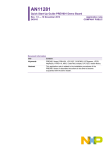
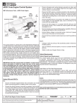
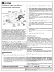
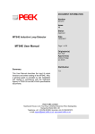
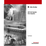
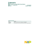
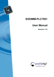
1
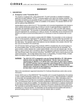
AN11562 PN7120 Low Power Mode Configuration Rev. 1.0 — 15 March 2015 299210 Application note COMPANY PUBLIC Document information Info Content Keywords NFC, PN7120, low power, discovery mode Abstract This application notes provides guidance on how PN7120 can be configured in order to reduce current consumption by using low power discovery mode AN11562 NXP Semiconductors PN7120 Low Power Mode Configuration Revision history Rev Date Description 1.0 20150315 Approved version for product release 0.1 20141223 Initial version of the document Contact information For more information, please visit: http://www.nxp.com For sales office addresses, please send an email to: [email protected] AN11562 Application note COMPANY PUBLIC All information provided in this document is subject to legal disclaimers. Rev. 1.0 — 15 March 2015 299210 © NXP B.V. 2015. All rights reserved. 2 of 21 AN11562 NXP Semiconductors PN7120 Low Power Mode Configuration 1. Introduction PN7120 implements an extreme low power discovery mode allowing decreasing up to 100 times the current consumption of the NFC Controller. This consumption reduction does not impact the user experience. This application note depicts how to use and tune this feature. 2. Low Power Discovery Mode concept PN7120 supports RF DISCOVERY defined within ACTIVITY specification from NFC FORUM (see [1]). PN7120 can be configured by following guidance depicted with NFC specification (see NCI specification [2]). The discovery loop consist of 2 phases: - POLL phase where NFCC emits RF field and sense for remote tag or peer NFC device - LISTEN phase where NFCC hears for remote reader of peer NFC device Average NFCC power consumption then depends on: - Technologies enabled in the POLL phase (lead to about 5ms to 80ms duration) - LISTEN phase duration - Antenna system used by the application (impedance of the RF system) Fig 1. AN11562 Application note COMPANY PUBLIC Regular Discovery loop All information provided in this document is subject to legal disclaimers. Rev. 1.0 — 15 March 2015 299210 © NXP B.V. 2015. All rights reserved. 3 of 21 AN11562 NXP Semiconductors PN7120 Low Power Mode Configuration Fig 2. Oscilloscope screenshot of Regular Polling loop @ 2Hz Current consumption is one of the main criteria during a NFC design-in within an embedded equipment. PN7120 NFC controller implements two modes of Low Power discovery additionally to the regular discovery mode: - Low Power Tag Detector mode - Hybrid mode 2.1 Low Power Tag Detector mode It consists on replacing each POLL phase of the regular discovery loop by a short LPCD pulse (few us of RF emission), allowing the PN7120 to check any change in the antenna proximity area. Whenever a change is detected, a regular POLL phase is triggered to verify the presence of tag or peer NFC device. The obtained new duty cycle allows achieving an extremely low current consumption. NXP provides a proprietary extension to the NCI protocol to enable and configure this mode (refer to PN7120 User Manual [4] for more details). AN11562 Application note COMPANY PUBLIC All information provided in this document is subject to legal disclaimers. Rev. 1.0 — 15 March 2015 299210 © NXP B.V. 2015. All rights reserved. 4 of 21 AN11562 NXP Semiconductors PN7120 Low Power Mode Configuration Fig 3. Discovery loop in Low Power Tag Detector mode Fig 4. Oscilloscope screenshot of Low Power Tag Detector mode @ 2Hz 2.2 Hybrid mode The aim of Hybrid discovery mode is to replace some regular POLL phases by LPCD pulses. This mode allows reducing significantly the average current consumption of the NFC Controller in comparison to the regular discovery loop, if the LPCD could not be used (infrequent cases where Low Power Tag Detector mode provide reduced user experience). NXP provides several proprietary parameters which can be configured through CORE_SET_CONFIG_CMD from the Device Host in order to enable this mode and define the amount of LPCD pulse (refer to PN7120 User Manual [4] for more details). AN11562 Application note COMPANY PUBLIC All information provided in this document is subject to legal disclaimers. Rev. 1.0 — 15 March 2015 299210 © NXP B.V. 2015. All rights reserved. 5 of 21 AN11562 NXP Semiconductors PN7120 Low Power Mode Configuration AN11562 Application note COMPANY PUBLIC Fig 5. Discovery loop in Hybrid mode Fig 6. Oscilloscope screenshot of Hybrid mode with POLL phase every 3 LPCD pulses @ 2Hz All information provided in this document is subject to legal disclaimers. Rev. 1.0 — 15 March 2015 299210 © NXP B.V. 2015. All rights reserved. 6 of 21 AN11562 NXP Semiconductors PN7120 Low Power Mode Configuration 3. Power consumption overview Current consumption of PN7120 depends on hardware integration within platform. Below figure depict the current consumption according the PN7120 IC state: Fig 7. Power consumption depending on IC state The wake-up time is about 2.5ms and the time to switch back in standby is a few hundreds of µs. The current consumption is standby state is about 20µA and about 6mA in wake-up state, while in RF emission state it highly depends on the antenna impedance and matching circuitry (refer to PN7120 Product Datasheet [3] for more details about power consumption figures). Following parameters impact the overall current consumption of the system: - - AN11562 Application note COMPANY PUBLIC Duration of RF emission o TPOLL, in Regular and Hybrid modes, relates to the Technologies enabled in the discovery loop o RF pulse, in Low Power Tag Detector mode, is about 150µs Duration of clock establishment o Using XTAL Tclock is only few us o Using an external system clock Tclock is from 1ms to 10ms (depending on platform capability) All information provided in this document is subject to legal disclaimers. Rev. 1.0 — 15 March 2015 299210 © NXP B.V. 2015. All rights reserved. 7 of 21 AN11562 NXP Semiconductors PN7120 Low Power Mode Configuration Reference configuration used for the overview: - Clock: XTAL - Antenna matching impedance: 28Ohms - TPOLL = 60ms - Hybrid mode: 1 regular RF polling for 3 RF pulses are considered Table 1. Current consumption of discovery modes Discovery loop frequency Discovery loop mode 1Hz 2Hz Regular 6,037mA 12,053mA Hybrid 1,623mA 3,411mA 75uA 130uA Low Power Tag Detector Here is a view of current consumption in Low Power Tag Detector mode with different configurations (antenna impedance and clock): Table 2. Current consumption depending on configuration Z = 80Ohms Z = 28Ohms Discovery loop mode XTAL XTAL Low Power Tag Detector @2Hz AN11562 Application note COMPANY PUBLIC 113uA 130uA All information provided in this document is subject to legal disclaimers. Rev. 1.0 — 15 March 2015 299210 Z = 28Ohms Z = 28Ohms SysClock 1ms SysClock 4ms 139uA 165uA © NXP B.V. 2015. All rights reserved. 8 of 21 AN11562 NXP Semiconductors PN7120 Low Power Mode Configuration 4. Configure Low Power mode 4.1 Host interface parameter description You can find below parameters needed to configure the PN7120 in Regular, Hybrid or Low Power Tag Detector modes. All those parameters can be modified by using the CORE_SET_CONFIG_CMD from NCI standard (see NCI specification [2]). Proprietary part is described in PN7120 User Manual [4]. Table 3. Discovery loop NCI Host Interface definition NCI Default Name Length Tag value Total_Duration 0x00 2 0xE803 Description Total duration of the single discovery period in [ms-Little endian coded] TLISTEN = Total_Duration - TPOLL Table 4. Discovery loop proprietary Host Interface definition Prop. Default Name Length Tag value Tag_Detector_CFG 0xA040 1 0x00 Description Tag detector setting as follows: - 0x00 Tag Detector disabled - 0x01 Tag Detector enabled - 0x81 Tag Detector with trace enabled Tag_Detector_Threshold_CFG 0xA041 1 0x04 Sets the detection level Tag_Detector_Period_CFG 0xA042 1 0x19 Time in steps of 8us to wait the measurement Tag_Detector_Fallback_Cnt_CFG 0xA043 1 0x50 Hybrid mode setting as follows: - 0x00 hybrid disabled - 0xXX Regular RF polling triggered after XX LPCD pulse PN7120 proposed a trace mechanism allowing to tune the sensitivity of the LPCD feature, later described in chapter 4.3. The format of the notification message is the following: Table 5. Offset AN11562 Application note COMPANY PUBLIC Format definition of notification message in trace mode Length value Description 0 1 0x6F NXP proprietary NTF 1 1 0x13 TAG DETECTOR message 2 1 0x04 Length of the message 3 2 0xXXXX Current reference value [Little endian coded] 5 2 0xXXXX Last measurement value [Little endian coded] All information provided in this document is subject to legal disclaimers. Rev. 1.0 — 15 March 2015 299210 © NXP B.V. 2015. All rights reserved. 9 of 21 AN11562 NXP Semiconductors PN7120 Low Power Mode Configuration 4.2 Description of main configuration Whatever the mode used, NCI Tag “Total_Duration” has to be set if you want a specific duty cycle. 4.2.1 Enable Regular Mode - Proprietary Tag “Tag_Detector_CFG”: o - Set to 0x00 Other proprietary tags are disregarded. 4.2.2 Enable Hybrid Mode - Proprietary Tag “Tag_Detector_CFG”: o - Proprietary Tag “Tag_Detector_Threshold_CFG”: o - Tune according to the system (see 4.3) Proprietary Tag “Tag_Detector_Period_CFG”: o - Set to 0x01 in order to enable the Tag Detector Keep to default value Extension Tag “Tag_Detector_Fallback_Cnt_CFG”: o This value has to be specified: If you want 1 regular POLL phase every N LPCD pulses, this tag has to be set to N+1 (e.g. setting this parameter to 0x04 lead to 1 regular POLL phase every 3 LPCD pulses) 4.2.3 Enable Low Power Card Detection Mode - Proprietary Tag “Tag_Detector_CFG”: o - Proprietary Tag “Tag_Detector_Threshold_CFG”: o - Application note COMPANY PUBLIC Keep to default value Extension Tag “Tag_Detector_Fallback_Cnt_CFG”: o AN11562 Tune according to the system (see 4.3) Proprietary Tag “Tag_Detector_Period_CFG”: o - Set to 0x01 in order to enable Tag Detector Set to 0x00 All information provided in this document is subject to legal disclaimers. Rev. 1.0 — 15 March 2015 299210 © NXP B.V. 2015. All rights reserved. 10 of 21 AN11562 NXP Semiconductors PN7120 Low Power Mode Configuration 4.3 Determining LPCD sensitivity In order to define easily the threshold for the system, PN7120 provide trace functionality sharing measurement values from internal HW modules for each LPCD pulse. Thanks to the information raised in these messages the adequate threshold level can be determined for the current system. 4.3.1 Pre-requisite 4.3.2 - DUT: system based on PN7120 IC - Non electromagnetic spacers of few centimeters - Oscilloscope with NFC coil Procedure Step 1: Preparation Place the DUT on top of a spacer in order to have some distance from the desk and turn the DUT antenna upward. Then ensure that no external interference could impact the measurement. For instance, avoid having other electronic devices around. Step 2: Set the DUT in Low Power Tag Detector with trace mode Enable the TRACE mode by setting the proprietary Tag “Tag_Detector_CFG” to 0x81. Then set the Tag “Tag_Detector_Threshold_CFG” to 0x10 defining the first threshold to evaluate. Verify if this configuration is well applied by reading back the parameter value with CORE_GET_CONFIG_CMD. Check that TRACE messages are broadcasted by the PN7120. For instance, if the system run android environment (refer to Android SDK for more information), use the following command from a computer connected through ADB (use ‘find’ instead of ‘grep’ from windows): adb logcat –vtime | grep “6f 13” Fig 8. AN11562 Application note COMPANY PUBLIC NTF messages from the LPCD mechanism All information provided in this document is subject to legal disclaimers. Rev. 1.0 — 15 March 2015 299210 © NXP B.V. 2015. All rights reserved. 11 of 21 AN11562 NXP Semiconductors PN7120 Low Power Mode Configuration Step 3: Evaluate the sensitivity for the default threshold For instance, if the system run android environment, use the following command (use ‘find’ instead of ‘grep’ from windows): adb logcat –vtime | grep “6f 13” > DUT_threshold_10.txt Wait some minutes in order to obtain around 2500 messages; then abort the process. Step 4: analyze logs Extract from the logs the list of values measured by the LPCD module. PN7120 in this mode will always set its reference value around the middle of measurements dispersion. To define the threshold maximum and minimum measurements have to be considered:Update the threshold to its new value by modifying Tag “Tag_Detector_Threshold_CFG”, then evaluate the new sensitivity set. For instance, if the system run android environment, use the following command (use ‘find’ instead of ‘grep’ from windows): adb logcat –vtime | grep “6f 13” > DUT_threshold_XX.txt Wait in order to have a large amount of data (more than 5000). Extract from the logs the number of times the LPCD was triggered due to wrong detection. Step 5: Optional – Fine tune this threshold Depending on the final application, it could be interesting to either maximize power saving or maximize RF performance. You can find below a table which summarizes the impact of wrong detections on the overall current consumption: Table 6. Impact of wrong detection on the current consumption Wrong detection 0,00% 0,01% 0,10% 1,00% 2,00% 5,00% 10,00% 20,00% 50,00% rate Current consumption (mA) 0,139 0,140 0,151 0,256 0,370 0,700 1,209 2,101 4,063 This table shows that a threshold with a wrong detection rate below 1 per 1000 has a limited impact (12uA). If you want to increase or decrease the threshold, perform again step 4 in order to verify the wrong detection rate. Step 6: Verify the overall behavior Once final value of threshold is defined, you could verify the overall RF behavior with a scope (see Fig 3). AN11562 Application note COMPANY PUBLIC All information provided in this document is subject to legal disclaimers. Rev. 1.0 — 15 March 2015 299210 © NXP B.V. 2015. All rights reserved. 12 of 21 AN11562 NXP Semiconductors PN7120 Low Power Mode Configuration 4.4 Determining reader communication range 4.4.1 Required material 4.4.2 - DUT: system based on PN7120 IC - Non electromagnetic spacers of different thickness (1 / 2 / 5 / 10 mm) - Oscilloscope with NFC coil - Tags to evaluate Procedure Step 1: Preparation Prepare the setup as depicted within the figure below. A spacer of 1cm has to be inserted between the NFC coil and the desk. Then another 1cm spacer will be positioned between the tag under and the NFC coil. Oscilloscope will be useful in order to identify if the LPCD is triggered or not. Fig 9. Setup to check detection limit Step 2: Find detection limit Enable the regular discovery mode (see 4.2.1). For each tag: 1- Start with no Spacer between the Card under test and the DUT 2- Place the DUT on top of the tag under test; 3- Verify that tag is detected several times (stability of the measurement): a. If yes: remove the DUT, add more spacer and go back to 2; b. If no: Tag detection limit is reached; AN11562 Application note COMPANY PUBLIC All information provided in this document is subject to legal disclaimers. Rev. 1.0 — 15 March 2015 299210 © NXP B.V. 2015. All rights reserved. 13 of 21 AN11562 NXP Semiconductors PN7120 Low Power Mode Configuration Step 3: Verifying detection limit Apply the Procedure of Step 2 for the Hybrid or Low Power Detector mode (see 4.2.2 or 4.2.3) instead of the regular discovery mode, in order to confirm the same Tag detection limit is reached in the targeted configuration. 5. Example with a reference device 5.1 Device description Device is equipped with a 4 turn antenna (45mm * 25mm). 5.2 Definition of the sensitivity threshold of this reference device On this reference device, here are results of the threshold definition study: Fig 10. Measurement dispersion for 5000 measurements For this device, here is the evolution of the wrong detection rate versus the threshold: AN11562 Application note COMPANY PUBLIC All information provided in this document is subject to legal disclaimers. Rev. 1.0 — 15 March 2015 299210 © NXP B.V. 2015. All rights reserved. 14 of 21 AN11562 NXP Semiconductors PN7120 Low Power Mode Configuration Fig 11. Wrong detection rate against threshold Here is a summary of the impact of the threshold on the reader range of the LPCD feature: Table 7. Detection range of the LPCD depending on the threshold Regular Threshold in Low Power Detector mode Card/Device discovery 0x08 0x09 0x0A 0x0C 0x0E mode ISO15693 58mm 46mm 45mm 43mm 38mm 33mm TOPAZ 37mm 35mm 35mm 35mm 33mm 31mm FELICA 31mm 31mm 30mm 30mm 30mm 29mm MIFARE 1K 41mm 39mm 39mm 38mm 35mm 28mm MIFARE 4K 28mm 27mm 25mm 24mm 22mm 20mm MIFARE plus X 22mm 21mm 21mm 20mm 19m 19mm NTAG203 38mm 34mm 32mm 32mm 31mm 29mm NTAG210 57mm 38mm 35mm 34mm 32mm 30mm MIFARE UL 40mm 38mm 36mm 36mm 34mm 27mm MIFARE ULC 20mm 20mm 20mm 20mm 19mm 19mm DESFIRE 19mm 19mm 19mm 19mm 19mm 18mm P2P against GS3 30mm 29mm 28mm 28mm 27mm 25mm N/A 0,22% 0,02% 0,00% 0,00% 0,00% 12mA 232uA 210uA 207uA 207uA 207uA Wrong detection rate Expected current consumption AN11562 Application note COMPANY PUBLIC All information provided in this document is subject to legal disclaimers. Rev. 1.0 — 15 March 2015 299210 © NXP B.V. 2015. All rights reserved. 15 of 21 AN11562 NXP Semiconductors PN7120 Low Power Mode Configuration There are 3 cases to consider in order defining the threshold value: Case 1: Detection range just meet acceptance criteria in regular discovery mode A Low threshold (i.e. 0x08 and below) has to be set. User experience will be favored compared current consumption (no margin at RF side). Case 2: Detection range is greater than acceptance criteria in regular discovery mode A medium threshold (i.e. 0x09 or 0x0A) has to be set. Giving an excellent tradeoff between current consumption and user experience. Case 3: Detection range is far greater than acceptance criteria in regular discovery mode A high threshold (i.e. 0x0B or more) has to be set. Current consumption will be favored compared to user experience (because we have margins at RF side). AN11562 Application note COMPANY PUBLIC All information provided in this document is subject to legal disclaimers. Rev. 1.0 — 15 March 2015 299210 © NXP B.V. 2015. All rights reserved. 16 of 21 AN11562 NXP Semiconductors PN7120 Low Power Mode Configuration 6. How to spy RF activity by using a scope 6.1 Pre-requisite - NFC device (the DUT) Oscilloscope with NFC coil or oscilloscope probe with alligator clip ground lead 6.2 Procedure Step 1 – Set the oscilloscope Set the X scale to a large value (i.e. 1s per division). Set the Y scale to 200mV per division. Set the mode to AUTO and place the trigger on the left part of the screen. Step 2 – Observe RF activity Bring the NFC coil or the oscilloscope probe on top of the device antenna: Fig 12. Spying RF activity of a NFC device using a coil or a probe The best in class approach is to put some distance between the device and the oscilloscope probe in order to not bring noise: AN11562 Application note COMPANY PUBLIC All information provided in this document is subject to legal disclaimers. Rev. 1.0 — 15 March 2015 299210 © NXP B.V. 2015. All rights reserved. 17 of 21 AN11562 NXP Semiconductors PN7120 Low Power Mode Configuration Fig 13. Recommended approach to spy RF activity 7. Abbreviations Table 8. Abbreviations Acronym Description AN11562 Application note COMPANY PUBLIC ADB Android Debug Bridge DUT Device Under Test HW Hardware IC Integrated Circuit mm Millimeter NFC Near Field Communication NFCC NFC Controller RF Radio Frequency LPCD Low Power Card Detection Z Impedance All information provided in this document is subject to legal disclaimers. Rev. 1.0 — 15 March 2015 299210 © NXP B.V. 2015. All rights reserved. 18 of 21 AN11562 NXP Semiconductors PN7120 Low Power Mode Configuration 8. References AN11562 Application note COMPANY PUBLIC [1] NFC FORUM Activity Specification 1.0 [2] NFC FORUM NFC Controller Interface, version 1.0 [3] PN7120 Datasheet [4] UM10819 - PN7120 User Manual All information provided in this document is subject to legal disclaimers. Rev. 1.0 — 15 March 2015 299210 © NXP B.V. 2015. All rights reserved. 19 of 21 AN11562 NXP Semiconductors PN7120 Low Power Mode Configuration 9. Legal information 9.1 Definitions Draft — The document is a draft version only. The content is still under internal review and subject to formal approval, which may result in modifications or additions. NXP Semiconductors does not give any representations or warranties as to the accuracy or completeness of information included herein and shall have no liability for the consequences of use of such information. 9.2 Disclaimers Limited warranty and liability — Information in this document is believed to be accurate and reliable. However, NXP Semiconductors does not give any representations or warranties, expressed or implied, as to the accuracy or completeness of such information and shall have no liability for the consequences of use of such information. NXP Semiconductors takes no responsibility for the content in this document if provided by an information source outside of NXP Semiconductors. In no event shall NXP Semiconductors be liable for any indirect, incidental, punitive, special or consequential damages (including - without limitation lost profits, lost savings, business interruption, costs related to the removal or replacement of any products or rework charges) whether or not such damages are based on tort (including negligence), warranty, breach of contract or any other legal theory. Notwithstanding any damages that customer might incur for any reason whatsoever, NXP Semiconductors’ aggregate and cumulative liability towards customer for the products described herein shall be limited in accordance with the Terms and conditions of commercial sale of NXP Semiconductors. Right to make changes — NXP Semiconductors reserves the right to make changes to information published in this document, including without limitation specifications and product descriptions, at any time and without notice. This document supersedes and replaces all information supplied prior to the publication hereof. Suitability for use — NXP Semiconductors products are not designed, authorized or warranted to be suitable for use in life support, life-critical or safety-critical systems or equipment, nor in applications where failure or malfunction of an NXP Semiconductors product can reasonably be expected to result in personal injury, death or severe property or environmental damage. NXP Semiconductors and its suppliers accept no liability for inclusion and/or use of NXP Semiconductors products in such equipment or applications and therefore such inclusion and/or use is at the customer’s own risk. Applications — Applications that are described herein for any of these products are for illustrative purposes only. NXP Semiconductors makes no representation or warranty that such applications will be suitable for the specified use without further testing or modification. Customers are responsible for the design and operation of their applications and products using NXP Semiconductors products, and NXP Semiconductors accepts no liability for any assistance with applications or customer product design. It is customer’s sole responsibility to determine whether the NXP Semiconductors product is suitable and fit for the customer’s applications and products planned, as well as for the planned application and use of customer’s third party customer(s). Customers should provide appropriate design and operating safeguards to minimize the risks associated with their applications and products. customer’s applications or products, or the application or use by customer’s third party customer(s). Customer is responsible for doing all necessary testing for the customer’s applications and products using NXP Semiconductors products in order to avoid a default of the applications and the products or of the application or use by customer’s third party customer(s). NXP does not accept any liability in this respect. Export control — This document as well as the item(s) described herein may be subject to export control regulations. Export might require a prior authorization from competent authorities. Translations — A non-English (translated) version of a document is for reference only. The English version shall prevail in case of any discrepancy between the translated and English versions. Evaluation products — This product is provided on an “as is” and “with all faults” basis for evaluation purposes only. NXP Semiconductors, its affiliates and their suppliers expressly disclaim all warranties, whether express, implied or statutory, including but not limited to the implied warranties of noninfringement, merchantability and fitness for a particular purpose. The entire risk as to the quality, or arising out of the use or performance, of this product remains with customer. In no event shall NXP Semiconductors, its affiliates or their suppliers be liable to customer for any special, indirect, consequential, punitive or incidental damages (including without limitation damages for loss of business, business interruption, loss of use, loss of data or information, and the like) arising out the use of or inability to use the product, whether or not based on tort (including negligence), strict liability, breach of contract, breach of warranty or any other theory, even if advised of the possibility of such damages. Notwithstanding any damages that customer might incur for any reason whatsoever (including without limitation, all damages referenced above and all direct or general damages), the entire liability of NXP Semiconductors, its affiliates and their suppliers and customer’s exclusive remedy for all of the foregoing shall be limited to actual damages incurred by customer based on reasonable reliance up to the greater of the amount actually paid by customer for the product or five dollars (US$5.00). The foregoing limitations, exclusions and disclaimers shall apply to the maximum extent permitted by applicable law, even if any remedy fails of its essential purpose. . 9.3 Licenses Purchase of NXP ICs with NFC technology Purchase of an NXP Semiconductors IC that complies with one of the Near Field Communication (NFC) standards ISO/IEC 18092 and ISO/IEC 21481 does not convey an implied license under any patent right infringed by implementation of any of those standards. 9.4 Trademarks Notice: All referenced brands, product names, service names and trademarks are property of their respective owners. DESFire — is a trademark of NXP B.V. I²C-bus — is a trademark of NXP B.V. MIFARE — is a trademark of NXP B.V. SmartMX — is a trademark of NXP B.V. NXP Semiconductors does not accept any liability related to any default, damage, costs or problem which is based on any weakness or default in the AN11562 Application note COMPANY PUBLIC All information provided in this document is subject to legal disclaimers. Rev. 1.0 — 15 March 2015 299210 © NXP B.V. 2015. All rights reserved. 20 of 21 AN11562 NXP Semiconductors PN7120 Low Power Mode Configuration 10. Contents 1. 2. 2.1 2.2 3. 4. 4.1 4.2 4.2.1 4.2.2 4.2.3 4.3 4.3.1 4.3.2 4.4 4.4.1 4.4.2 5. 5.1 5.2 6. 6.1 6.2 7. 8. 9. 9.1 9.2 9.3 9.4 10. Introduction ......................................................... 3 Low Power Discovery Mode concept ................ 3 Low Power Tag Detector mode .......................... 4 Hybrid mode ....................................................... 5 Power consumption overview ............................ 7 Configure Low Power mode ............................... 9 Host interface parameter description ................. 9 Description of main configuration ..................... 10 Enable Regular Mode ...................................... 10 Enable Hybrid Mode ......................................... 10 Enable Low Power Card Detection Mode ........ 10 Determining LPCD sensitivity ........................... 11 Pre-requisite ..................................................... 11 Procedure......................................................... 11 Determining reader communication range ....... 13 Required material ............................................. 13 Procedure......................................................... 13 Example with a reference device ..................... 14 Device description ............................................ 14 Definition of the sensitivity threshold of this reference device............................................... 14 How to spy RF activity by using a scope ........ 17 Pre-requisite ..................................................... 17 Procedure......................................................... 17 Abbreviations .................................................... 18 References ......................................................... 19 Legal information .............................................. 20 Definitions ........................................................ 20 Disclaimers....................................................... 20 Licenses ........................................................... 20 Trademarks ...................................................... 20 Contents ............................................................. 21 Please be aware that important notices concerning this document and the product(s) described herein, have been included in the section 'Legal information'. © NXP B.V. 2015. All rights reserved. For more information, visit: http://www.nxp.com For sales office addresses, please send an email to: [email protected] Date of release: 15 March 2015 299210 Document identifier: AN11562