1
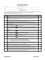
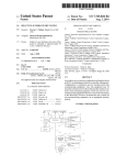
CLEANVOLT ELECTRIC HOT WATER AND STEAM BOILERS MANUAL OPERATIONS AND MAINTENANCE MANUAL TRIAD Boiler Systems, Inc. West Chicago, IL 60185 Ph: 630-562-2700 Fax: 630-562-2800 Email – [email protected] 04/16/11 TRIAD BOILER SYSTEMS, INC. !!!!!! ATTENTION !!!!!! READ THIS MANUAL VERY CAREFULLY! IT IS VERY IMPORTANT! DO NOT SKIP OVER THE BOILER NOTES AND WARNINGS THAT ARE IN SECTION I WHICH CONTAIN INFORMATION THAT MUST BE READ AND UNDERSTOOD. THESE ITEMS IN PARTICULAR ARE VERY IMPORTANT: BOILER SAFETY - Read the Warnings in this manual. WATER TREATMENT/QUALITY (See Section I & VII for more detail) - pH between 7 and 9 - Total Dissolved Solids (TDS) levels < 2000 ppm (Levels above these can cause foaming / surging) NEAR BOILER PIPING - See Section V for recommended near boiler piping FEEDWATER - Temperature of 160°F - Temperature below 200°F requires an oxygen scavenger FIELD STARTUP CHECKLIST (See Section VII) TRIAD BOILER SYSTEMS, INC. Steam Boiler Operations and Maintenance Manual TABLE OF CONTENTS: Section I BASIC BOILER WARNINGS Section II BOILER MODEL INFORMATION Packing Slip Wiring Diagrams Section III INSTALLATION AND STARTUP INSTRUCTIONS Section IV SEQUENCE OF OPERATIONS Section V OPERATIONAL TESTING Section VI OEM COMPONENT PRODUCT DATA Section VII GENERAL MAINTENANCE Section VIII TROUBLESHOOTING Retain this manual and keep it readily available, typically near the boiler. TRIAD BOILER SYSTEMS, INC. Section I BASIC BOILER WARNINGS STOP! READ THIS FIRST. TRIAD STRONGLY RECOMMENDS THAT THE SYSTEM DESIGN ENGINEER THOROUGHLY REVIEW THIS MANUAL BEFORE INSTALLATION AND STARTUP. ALL OPERATORS SHOULD BE FAMILIAR WITH THIS MATERIAL - THIS MANUAL SHOULD BE READ, ITS MATERIAL UNDERSTOOD, AND ITS INSTRUCTIONS FOLLOWED. THIS MANUAL SHOULD BE READILY AVAILABLE IN THE BOILER ROOM AS A REFERENCE. The first and most critical step in the installation and startup procedure for any boiler system is to carefully read and understand the WARNINGS in this section. The second step is to review this entire manual including the original equipment manufacturer's (OEM) component instruction information included in Section VI. The third and very important step is to ensure that the system and in particular the water and electrical components have been properly installed and meet local codes before placing the boiler in operation. The fourth and ongoing step is to ensure that the system is properly maintained. WARNING: It is important to make sure the main power switch and all power to the boiler is OFF prior to working on the boiler. NOTE: Consult local building and safety codes before proceeding with work. The operation of this WARNINGS equipment by the owner and operating personnel must comply with all requirements of the authorities or regulations having jurisdiction. In the absence of such authorities, the installation must conform to the safety codes set forth by both the American Society of Mechanical Engineers (ASME) and the National Electric Code (NEC). NOTE: Correct near boiler piping is critical to the proper operation of steam boilers. Consult Factory Representative for recommended near boiler piping diagrams. NOTE: Triad highly recommends that boiler feed water be treated before it enters the boiler. The water in the boiler should have a pH level of between 7.5 and 8.5, and in no case above 9. If feed water temperature is below 140°F it also requires an oxygen scavenger. See WATER in Section III of this boiler manual. NOTE: If using a condensate return tank; (i) its capacity should be large enough to satisfy boiler consumption and maintain proper return tank temperature, (ii) it should be vented, (iii) the vent pipe should not be downsized, which could cause pressure to build up in the tank; (iv) return pipes should not be insulated to avoid overheating the return system that could cause a vapor lock in the pump. NOTE / WARNING: Only properly trained personnel should install and maintain the water gauge glass on a steam boiler. Wear safety glasses during installation. Improper installation or maintenance can cause immediate or delayed breakage resulting in injury and/or property damage. Never clean the gauge glass while pressurized or in operation. WARNING: If using soap for leak testing, be careful as some soap are corrosive to certain metals. Clean all piping with water after the leak check has been completed. WARNING: Do not tamper with the low water safety cut off. TRIAD Boilers can provide years of dependable SECTION I service with proper maintenance and by carefully following the instructions and information provided in this manual. Failure to follow the directions and warnings can result in property damage or serious injury. Independent Operation -- the boiler controls and accessories are activated by the "Call For Heat" circuit. As a result these components can be supplied with electricity and/or operate without warning. It is imperative that all power is removed and the control signal(s) is "locked out" before any maintenance is done on the boiler system. Operating Limits -- Boilers heat water under pressure. When water is heated above its boiling point it can flash to steam if the pressure is removed. In addition, "dry firing a boiler" (applying heat to a boiler with inadequate water inside) can result in an extremely destructive and hazardous condition caused by the rapid and potentially explosive buildup of extreme pressures and temperatures. According to the National Board Bulletin/Fall 2007, it is a good idea to post signage near the boiler that states something similar to the following: EXPLOSION WARNING - Do Not Introduce Water Into or Onto an Overheated Boiler The boiler contains several limit controls to prevent excessive temperatures, but make sure these controls are properly set, maintained, and operated. CAUTION: Boiler controls must NEVER be bypassed. If any manual reset control device has “tripped”, the boiler control must NEVER be reset until the system has been thoroughly checked by a qualified technician. Failure to follow this warning can result in damage to the vessels and serious personal injury. The following is a list of Recommendations for a Boiler Room derived from the National Board of Boiler and Pressure Vessel Inspectors. 1) Keep the boiler room clean and clear of all unnecessary items. The boiler room should not be considered a storage area. 2) Ensure that all personnel who operate or maintain the boiler room are properly trained on all equipment, controls, safety devices and up-to-date operating procedures. of all potentially dangerous items like flammable materials that could cause a fire. Check for deterioration and possible leaks. 4) Conduct a thorough inspection by a properly qualified inspector such as one who holds a National Board commission. 5) After any extensive repair or new installation of equipment, make sure a qualified boiler inspector reinspects the entire system. 6) Monitor all new equipment during startup to ensure its proper operation according to the manufacturer’s specifications. 7) Establish a preventive maintenance schedule based upon the manufacturer's recommendations and a safety-testing program that follows CSD-11995, Part CM and the manufacturer's recommendations 8) Establish a checklist for proper startup and shutdown of boilers and all related equipment according to the manufacturer's recommendations. 9) Observe equipment extensively before allowing automatic operating systems to be used without supervision. 10) Use boiler operating log sheets, maintenance records, and the manufacturer's recommendations to establish a preventive maintenance schedule based on operating conditions, repair, and replacements performed on the equipment. TRIAD reminds end-users that boilers and boiler rooms may fall under many code and regulatory requirements with local jurisdiction usually controlling. Installation should be carried out by competent personnel in accordance with the standards of the National Fire Protection Association, National or Canadian Electrical Code. State and jurisdictional codes beyond the scope of the ASME Boiler and Pressure Vessel Codes should be followed in all cases. Jurisdictional authorities must be consulted prior to installation. TRIAD very strongly recommends that a competent and knowledgeable system design engineer be given design and implementation responsibility. 3) Before startup, ensure that the boiler room is free WARNINGS SECTION I WATER Properly treated vessel water is highly important, and critical for normal boiler service life and correct operation. This is water free of excessive minerals and gases with a nominal pH of 7.8 ± 0.5. A pH reading of around 10.0 or higher can result in priming and surging, which can cause wet steam and/or flooding of the steam supply and steam header. A pH level only a single digit away from these recommendations can make a dramatic difference. This is because each increasing level of pH is ten times greater than the prior level. So for example, a pH of 8 is ten times more acidic than a pH of 9, and one hundred times more acidic that a pH of 10. Conversely, a pH of 8 is ten times more basic (alkaline) than pH of 7. Water Items pH TDS Hardness CaCO3 Levels 7.5 to 9.5 <2000 ppm <10 ppm (Calcium Carbonate) Alkalinity Organic Carbon Iron Suspended Solids <300 ppm No sheen or Foam (1) Colorless Liquid (2) No visual turbidity (3) (1) Organic Carbon – After a water sample sits for 10 minutes there should be no visible solids. (2) Iron – Hold a water sample against a white background and there should be no visible yellow, red, or orange tinge. (3) Suspended solids – Vigorously shake a water sample for 30 seconds. There should be no visible sheen or foam. Water samples should be taken from the lower part of the boiler, not from an area higher up such as the gauge glass. Raw makeup water (feedwater) contains dissolved oxygen, suspended solids such as dirt, minerals and organic materials that can cause corrosive failure and a buildup of scale inside the boiler. One way to lower the amount of dissolved oxygen in feedwater is use a sparge tube. This injects steam into the feedwater to increase the temperature to 180°F to remove oxygen. Scale is a very effective insulator that will cause a loss of heat transfer efficiency and eventually tube sheet failure. Hard water results in a high amount of suspended solids. This condition is not covered under the boiler warranty. Water that is too soft can be even more aggressive, WARNINGS so a minimum hardness is usually recommended. And both soft and hard water conditions can result in boiler surging, which can produce wet steam. Too much oil present in the water will also cause foaming and surging. Other items that also are harmful to the boilers include silica, iron, chlorides, and phosphates. Following are several terminology items: water treatment Alkalinity – Levels of this determine the ability of acids to be neutralized in water. Alkalinities can form carbon dioxide in steam, which is the primary culprit in corrosion in condensate lines. High alkalinity also causes foaming and carryover in boilers. High levels can be from infrequent blowdowns, or an overdose of alkaline water treatment chemical. Chlorides – The higher the levels, the more corrosive the water. These can be controlled by increasing the amount of corrosion inhibiter or changing the type of inhibiter used. Dissolved Oxygen – High levels in the feedwater and boiler can cause pitting. It is very difficult to stop pitting once it has started, and can proceed very quickly. Preheating feedwater can help prevent this. Iron (Oxides) – Iron can start in the raw feedwater, condensate return water, or from directly in the boiler due to corrosion. It can be a major culprit in developing of scale. Oil – Oil can get into boiler water from various sources, including high levels in a new boiler, or from the condensate. It can contribute to scale formation and cause foaming. pH – This is a measure of the level of acid or base of water. If too low (acidic) corrosion will increase, if too high then scale can develop. It can also cause water carryover. It is very important to continuously monitor pH levels. Phosphates – High levels can cause scale formation. It usually comes from some type of pollution in the groundwater. Sodium Sulfite – This is used to remove dissolved oxygen from the feedwater before it gets to the boiler. It reacts with oxygen to produce sodium sulfate (versus sulfite). Feedwater at all times should have slightly more than enough sodium sulfite to consume all the dissolved oxygen. If not fed continuously, the boiler may not be protected from oxygen corrosion. This is a very important aspect of SECTION I water treatment. TDS – Total Dissolved Solids is undissolved organic matter such as dirt and silt in the water. This can cause high hardness in feedwater, and result in foaming or carryover. A thorough review by a qualified water treatment system specialist should be done, and their recommendations followed. . WARNINGS SECTION I TRIAD BOILER SYSTEMS, INC. Section II BOILER MODEL INFORMATION This section includes a copy of the packing list for the boiler system that shows the model number and input firing rate that defines the size and capacity, and a wiring diagram for future reference. If you should have a question or need service, it is important to provide the following information: Boiler Model Serial Number for boiler and burner Date of Installation Job Number, usually shown on packing list. The boiler model and serial numbers can be found on the boiler registration. WARNING: Please read the manual completely before attempting to place the boilers into service. It is extremely important that all of the information in this manual be studied before attempting to operate the boilers. Failure to follow the directions and warnings can result in property damage or serious injury. Each TRIAD Boiler is certified to meet or exceed the requirements of the American Society of Mechanical Engineers (ASME) Code for pressure vessels. Each boiler is registered with the National Board of Boiler and Pressure Vessel Inspectors (National Board, NBBI). TRIAD Boiler Systems, Inc. is not responsible for general system design. The boiler is only one component of the entire heating system. Only trained and qualified individuals experienced in boiler room mechanics and local code requirements should be used to install the system. Specifications are subject to change without notice. MODEL INFORMATION SECTION II ABBREVIATIONS AND TERMS ASME -- American Society of Mechanical Engineers -- boiler engineering code specifications. BTU/hr -- British Thermal Unit per hour, heat to raise 1 gallon of water 1F. Blow-Down – cleaning, opening a valve to release quantities of steam and water. Call For Heat -- completion of the thermostat control loop T-TY circuit. Condensate – condensed steam, phase changed back to water giving up latent heat. Cycle -- from Call For Heat to shut-off after call is satisfied. Dry Fire -- heating a vessel with insufficient water, extremely hazardous. Flash -- water heated above boiling will convert violently to steam on loss of pressure. Gauge Glass – special glass tube displaying internal boiler water level. L.W.C.O. -- Low Water Cut Off -- controls boiler by monitoring water level. Latent Heat – heat associated with phase conversion from liquid to steam. Lever Test -- safety relief valve, raise manual lever to check operation, releases steam and water. Low Pressure – 0 to 15 psig steam system. MBH – 1000 btu per hour. NBBI -- National Board of Boiler and Pressure Vessel Inspectors, aka: The Board. Near Boiler Piping – equalizer, header, feed, drain, and Hartford loop connections. Nominal -- under all conditions being within expected parameters. OEM -- Original Equipment Manufacturer, a purchased product component. Operator -- someone trained and competent to monitor in-use boiler systems. Pressure Bound Vessel -- NBBI registered ASME code built boiler shell. Pressure Controller – limits boiler operating pressure, part of boiler control circuit. PSIG -- pounds per square inch gauge (vs absolute), typically used as just psi. Raw Water -- untreated for ph, solids, dissolved minerals and gasses, and organics. Remove From Service -- properly disconnect and render inoperative. Safety Relief Valve -- ASME rated steam relief valve matched for pressure and heat capacity (15 psig max.). Scale - the solidification of dissolved minerals from water, typically carbonates. Sight glass – glass port for viewing firebox. Skim Tap – a flange at the water line for the cleaning process required for new (and dirty) boilers. Staging -- the controlled firing in sequence of modular boilers to meet varying demands. System Design Engineer -- responsible for system compliance and specifications. Technical Service -- knowledgeable, licensed, trained, experienced, and qualified. Thermal Shock -- cyclic metal fatigue caused by excessive heat differentials. Tripped -- a device that has been activated and must be physically re-set. UL -- Underwriters Laboratories. Water Hammer – water driven at high speeds by steam and trapped air. Water Treatment -- controls ph, hardness, dissolved minerals and gasses, and organics. MODEL INFORMATION SECTION II TRIAD BOILER SYSTEMS, INC. Section III INSTALLATION & STARTUP INSTRUCTIONS above 15 psi, which normally are required to be piped to overhead discharge outside, safely away from personnel. Hot water boilers may be equipped with an air vent pipe on the top of the boiler. Plumb this connection to the expansion tank or install an automatic air vent on this pipe. Electrical equipment can be damaged if exposed to adverse weather. The boiler should be stored inside. The electrical panel and controls should be covered with plastic throughout all construction of to avoid accumulation dust and moisture on the controls and load components. The contactors can be damaged by dust/dirt in the mechanism. The direction of flow through hot water boilers and water heaters must be from the inlet to the outlet (ie, bottom to top). Do not reverse these connections. WARNING: If the equipment is to be placed in a room with little or no ventilation, a supply of ducted filtered air may have to be brought to the lower portion of the control cabinet to limit the control cabinet interior temperature to (122°F) maximum. ELECTRICAL CONNECTIONS: NOTE: Standard electric boilers/water heaters are not suitable for placement on combustible flooring. Leave a permanent space for element removal opposite the element access panels as shown on the Dimensional Drawing (DD) and 36 inches opposite electrical panels. Note: 42” is required opposite the electrical panels if the opposing surface is conductive. Be sure to keep electrical panels and controls covered at all times while construction work is in process. CAUTION: Do not use the equipment housing top for scaffolding. NOTE: Do not oversize feed water piping and valves on steam boilers, as this may result in severe pressure fluctuations during feed water cycles if the fill rate is too rapid. Power Feed Wirinq: The recommended wire size is listed on both the unit's Bill of Material (BOM) and the Wiring Diagram (WD). Also, the full load amperage and maximum voltage are stamped on the unit's nameplate. The feeder must be sized for l25% of the full load amperage in accordance with Article 424-3 of the NEC. The wiring must have insulation rated 75°C or greater. Copper wiring is recommended for all power connections. The recommended size is noted in the "Notes" on the wiring diagram. CAUTION: Do not exceed the maximum voltage as listed on the nameplate. For resistance loads, amperage increases proportionally with voltage. EQUIPMENT GROUNDING CONDUCTORS: The unit is equipped with grounding plug(s) inside the power panel(s).The grounding conductors must be installed and sized in accordance with NEC Article 424-14. The recommended size is noted in the "Notes" on the wiring diagram. PIPING CONNECTIONS: CAUTION: The pipe extensions outside the unit are usually the extensions of pipes which are permanently welded into the unit's vessel. Normally the only removable (threaded) connection is the drain pipe. DO NOT ATTEMPT TO REMOVE ANY OTHER PIPING! Install the safety relief valve(s) on the pipes provided. Plumb the relief valve outlet connections full size to the floor drain. Check local codes for proper safety valve discharge for steam boilers INSTALLATION Control Wiring Alteration of, or additions to, control wiring may void both the Underwriters Laboratories Listing and the Manufacturer's Limited Warranty. Field-installed controls and control connections and modifications must be approved in writing by the Factory. NOTE: All power connections are 3-Phase, 3-Wire. (Unless unit is specifically single phase) There is no provision for a neutral connection; (ie, the unit SECTION III should not be wired "wye"or "star"), The system and the boiler/water heater must be thoroughly flushed before the final fill. Steam boilers should be "boiled out" before operation. CLEANING STEAM BOILERS (BOIL OUT/SKIMMING) New steam boilers need to be thoroughly cleaned before being placed into normal operations. After installation and before the boiler is officially in service the pressure vessel should be cleaned of any oil film, dirt, and other impurities. The boiler should be ready for firing and the operator should be fully familiar with the operation of the boiler and follow instructions contained in this manual. The operating conditions of all auxiliary equipment should be formally checked out. Boil outs and skimming the water surface are methods of cleaning a steam boiler and the system to remove oils and contaminates from the water. It is performed by heating the boiler to temperature and then skimming off the top of the water at the water line. New boilers require repetitive cleaning during the first few weeks of continuous operation. Existing boilers need cleaning whenever the water level begins to surge, prime or bubble. It is usually best to let the boiler operate for several days to clear out the system before doing the initial cleaning operation. See section VII. The manual blow-down valves on the LWCO controls should be operated at least 2 to 3 times a day during the first two weeks of boiler operation. After that, manual blow-down should be performed at least daily on all operating boilers – see LWCO manufacturer’s instructions and Section VII. Three possible methods are suggested depending on the conditions, age and size of the systems. . 1. The simplest method is to run the system and dispose all condensate for several days until it runs clear (if allowed by local code). This method is the least effective. 2. Another method, which is more effective is the following: A) Run the boiler to a low boil temperature slightly above 217°F or 2 psig. Then turn the boiler off. B) Isolate the boiler from the rest of the system and allow the boiler to cool until no pressure is showing on the gauge. C) Open the skim tap shut-off valve carefully to “skim” off the top level of water – be careful of flash. Power the boiler feed water solenoid open to replace the water being “skimmed-off” D) Capture a sample of the spill into a suitable container about 2 inches across and 9 inches deep and heat it to a boil. If the water foams, surges or forms large bubbles, then dirt and oil remain in the system. Water Treatment: The internal materials of boilers are steel, incoloy and cast iron, all of which are compatible with standard boilout compounds. In lieu of a commercial boilout compound, the following mix of chemicals can be used for every 1,000 gallons of water: 30lbs tri-sodiumphosphate (Na3PO4) 5 lbs caustic soda (NaOH) 2 lbs ordinary detergent These chemicals should be dissolved in warm water prior to their addition to the boiler. The boiler should be heated for at least 3 hours, then drained and flushed. NOTE: Standard hot water boilers are suitable for ethylene glycol mixtures up to a 50/50 blend. The gauge glass should be dry above the water line and the water line should be stable. Changes in the gauge glass water level or the presence of visible moisture above the water line or water droplets carrying over from the top suggest the need for a good cleaning. INSTALLATION 3. A third method is chemical cleaning, which is the most effective method. There are special trademarked chemicals available on the market for boil outs. It is strongly recommended that a water treatment consultant with expertise in boiler water chemistry be available to provide direction as required. Failure to completely clean a new boiler will result in wet steam production and erratic boiler performance. The oil in the water will lead to foaming, and surges (“priming”) in the water level, typically visible through the gauge glass. SECTION III You can also refer to the instructions in Section 7 of the ASME Boiler Code for more detail on cleaning pressure vessels. Depending on the age and condition of the system, the system may require several cleaning cycles Replace the control transformer fuse which was previously removed. 2. Remove element access panel(s) and open the doors to the electrical control panel(s). Run an inspection of the tightness of all elecgrical connections (ie)at fuse lugs, power entrance lugs, contactors, and heating elements). PRE-STARTUP INSPECTION Minimum equipment required for startup and troubleshooting: Volt-Ohm Meter Clamp-On Ammeter Megohm Meter Torque Wrench - inch lbs Torque Wrench - foot lbs Mechanical System Checks: Note: See Maintenance Section on rechecking the torque on these components after an initial break-in period. Typically one to two weeks after startup and then at least annually. Plumbing Connections Completed Inlet/ Makeup water? Discharge/Outlet? Drain/Blowdown? Relief/Safety Valve discharge? Feed pumps/Circulating Pumps Pumps wired, connected and checked for proper rotation? Is the boiler filled to the proper level with water? System Flush Has the System been flushed? Has the unit been cleaned construction debris? All branch circuit connections should be tightened to 40-50 inch lbs. (actual value listed on components). Torque to avoid component damage from heat buildup. This tightness inspection is vital, because the vibration during shipment can often loosen electrical connections. If this is not done, damage may occur to component parts when power is switched on, and those damaged parts will not be covered under the manufacturer’s warranty. of all Valves Are all valves in the proper open or closed positions? Electrical System Checks WARNING! All POWER Supplying boiler should be off and locked out! 3. With an ohmmeter, check the resistance between the phases on the load side of the contactors. Each should read the same and approximately what is shown on the wiring diagram. 4. Check the electrical panels for loose material, dust and/or moisture. Thoroughly vacuum the panels if dust or foreign materials have accumulated. If there has been severe exposure to dust, the contactors should be disassembled and cleaned. Dust in the contactors will cause contactor chattering and eventual destruction of the contacts. All components should be clean and free of dust, moisture, and foreign matter. 5. Verify that field-installed control and load connections have been properly completed. 6. Check the tightness of all control circuit connections. HEATING ELEMENT: When the unit's main power switches are OFF and locked out: CAUTION Moisture in the elements may result in damage to the elements. 1. Remove one of the unit’s control circuit transformer primary fuses. Then check the resistance phase-to-phase or phase-to-ground. With a megger (500VDC minimum) check contactor load side terminals to ground. If a reading of <1 megohm is obtained, consult with the Factory. NOTE: There is a possibility that during shipment or storage prior to operation the elements may accumulate moisture. The moisture will turn to steam when the elements are turned on and may rupture the element casing. INSTALLATION SECTION III How to check Elements for Moisture: Take a reading with a megger between the contactor terminals (load side) to ground for each contactor. Moisture is present if the reading is less than 1 megohm for standard 3-phase connection. Removal of Moisture in Element (Method #1) Remove the fuses going to that contactor. The fuses should be removed so that during the first day of operation the affected element will not be energized allowing the hot water to drive the moisture out at a controlled rate. Removal of Moisture in Element (Method #2) An alternate heating method is to direct a heat lamp at the suspect element, or remove the element, bake it in a 200°F oven for 8 hours, then reinstall and rewire. After completion of either of the above methods for moisture removal, re-check the element with a megger. When the reading indicates an acceptable level the element may be put in operation by replacing the fuses. Replace all Element Access Panels and close electrical/control panel doors. INSPECTION POWER/VOLTAGE Verify the boiler ON/OFF control switch is in the "OFF" position. Close the boiler main power switch, switch the control switch to "ON" and then: 1. Check the phase-to-phase voltage at the main terminals in the boiler electrical panel. The phase-tophase voltage between any two of the phases must not exceed the boiler nameplate voltage. 2. Check the voltage at the boiler control circuit fuse. It should be between 105 volts and 125 volts. 3. Open the boiler main power switch. If all of the above prove satisfactory, replace all covers and close all doors and proceed with Startup Instructions. . STARTUP INSTRUCTIONS: Controller: The controller is the pressure or temperature sensing device which controls the operation of the contactors directly or indirectly via the step control. NOTE: (For Water Heaters) The maximum water temperature for lined vessels is 160°F except for cement lined vessels which can operate at 180°F. NOTE: (For Hot Water Boilers) Outdoor reset (dualbulb) controllers are set at the temperature at which the boiler should operate when the outdoor temperature is 70°F (this outdoor reference temperature is adjustable on most solid state controls; fixed on Honeywell T991B controllers). The reset ratio (fixed on Honeywell T775) is the number of degrees the boiler control temperature will increase for a 1 degree decrease in outdoor temperature. Throttling Range is the number of degrees (or psi) the outlet water temperature (or steam pressure) must change to drive the step controller from full-off to full-on. If the controller is set at 160°F, and the throttling range is set for 10°F, the step controller will be full-on at 155°F (1/2 of throttling range below set point) and full-off at 165°F (U2 of throttling range above set point). The more stable the load on the unit (from system demands), the smaller the throttling range may be set. High Limit (Temperature or Pressure) Set the automatic reset high limit 10°F (or 5 psi),or twice the throttling range, whichever is greater, above the setting of the controller. Manual reset limits should be set slightly higher than the automatic reset limits. For steam boilers, the manual reset high limit should be set at least 10% below the safety valve set pressure. Low Water Cutoffs These cut offs are always factory-set. If additional cut offs are field-installed, the cut-off levels should be at least three inches above the highest heating element. Manual reset cutoffs should be set below automatic reset cutoffs. Low Limit Sensors (Temperature or Pressure) Low limits should be set below the controller setting by at least the same margin as specified for high limits to be above the controller setting. Relief Valve The relief valve should NEVER function under normal operations. If it has then something needs to INSTALLATION SECTION III be adjusted. Many codes require periodic testing and replacement of relief valves -- the user must meet local code requirements. Many codes require that the safety relief valve be freely vented to the outside atmosphere (potential line freezing must be considered). Relief valves are sized for both their pressure rating and their BTU/hr load. Replace only with properly sized, ASME approved units designed for steam systems -- SEE MANUFACTURER'S TAG ATTACHED TO THE VALVE. control (circuit board inside cabinet) will light up one at a time, indicating that step control is operating properly. (Note: The enable pilot lights or contactors will not be activated at this time since the "enable/disables" switches are in the off position.) OPERATING INSTRUCTIONS For units with ON/OFF/PREHEAT switches, only part of the steps (approximately 25%) may be activated when the switch is down in the “PREHEAT” position. This PREHEAT position is now rarely used. 1. With the unit's control power ON/OFF or ON/OFF/PREHEAT switch "OFF", close the main power switch(es). NOTE: Units with shunt trip disconnects and remote 120-volt control power may require turning the control power switch "ON" and activating the 120volt control power, before closing the main power switch(es). For units equipped with electric door interlocks do not attempt to open electrical panel doors after the main switch is closed. The lock tabs are mechanically restrained by the electric interlocks. With the step control full on, individually enable each step. The respective pilot light should light and the contactor(s) applying power to the respective elements. If a PREHEAT switch is used, when the outlet water temperature (or steam pressure) is at or near set point turn the ON/OFF/PREHEAT switch "OFF", then to "ON" again, The controls will recycle to the no-load condition. The steps should then begin to cycle on as needed, and all of the steps may come on if necessary. 2. Switch all the "enable/disable" pilot switches to the "off" position (toggle down). 3. If a separate 120-volt power source is provided, close its disconnect switch. 4. Turn the control power ON/OFF ON/OFF/PREHEAT switch to "ON". or 5. Alarm and reset circuits 6. If the alarm sounds when the control switch is turned “ON”, then depress the alarm silence button. Check the unit to make certain that no limit condition exists by noting if the alarm pilot is illuminated. The alarm will sound momentarily on some units when power is initially applied. 7. Units with Manual Reset Button(s) may require resetting of the manual reset switch upon initial application of power, and after the interruption or power or the trip-out of a limit control. Sequencing of Elements Circuits: On units with step controls, the unit will always start with no steps energized. As the steps begin cycling on, the LED's on the step INSTALLATION SECTION III TRIAD BOILER SYSTEMS, INC. Section IV SEQUENCE OF OPERATIONS ACTIVATION OF HEATING ELEMENT CIRCUITS Contactors: The heating elements are energized by pilot operation. That is, the power to an element circuit is supplied through the contacts of a contactor. The contactor is activated (on a call for heat) by the closure of a temperature (or pressure) switch or by a contact in the step control circuit. Fuses: All power leads to the elements are fused. The fusing is on the line side of the contactors. SEQUENCING CONTROLS: Stage Control Circuit: In this type of circuit, the contactor coils are energized directly by the contacts of immersion thermostats (or pressuretrols). There is usually a thermostat (or pressuretrol) for each stage; or a multi-stage thermostat (or pressuretrol) may be provided in some cases. The safety limit devices (high temperature, low water, etc) interrupt the power to the contactor coil circuits. PROPORTIONAL STEP CONTROLS: Step Control Sequence: The controller senses the unit’s water temperature (either via 135-ohm device or thermistor) or steam pressure (either via 135-ohm device or 4-20ma transducer). The output signal of the controller causes the step control to sequence the steps on, or off, depending on whether the unit’s output is below or above stepoint. When one of the switches closes on the step control, a contact or coil(s) is energized in a stepwise fashion. This type of step control will midposition (bring on half of the steps) when the unit's water temperature (or steam pressure) is at set point. For example: an 8 step steam boiler with the pressure controller set at 12 PSIG, will have 4 steps on when the boiler steam pressure is at 12 PSIG. PROGRESSIVE SEQUENCE STEP CONTROLS: These controls are provided as standard and include Selectronix SLC series and Viconics' model R851B. They provide first-on, first-off staging of the element INSTALLATION circuits. As the unit's temperature (or pressure) drops below set point, the control brings on more steps. As the temperature (or pressure) increases and approaches set point, the step control drops out stages. The first step to drop off is the one that has been on the longest. This provides even usage of the system's components. LINEAR SEQUENCE STEP CONTROLS: This type of step control is limited to the same Selectronix models and Viconics' model R8518. In this sequence progression, the control applies power by progressing from Step 1 to the maximum number required to satisfy the load, and then decreases power by retracing this sequence down toward the first step. NOTE: Refer to the applicable vendor literature provided on the step control installed in your unit. RECYCLE FEATURE: All step controls now incorporate the recycle feature which returns the step control to the no-load condition upon loss of control power. MANUAL STEP ENABLE/DISABLE TOGGLE SWITCHES: All units with >1 step include manual enable/disable toggle switches to provide a positive “off” override of each step. These are used to disable a faulty step, limit total output or allow for a slow preheat. PREHEAT SWITCH (BOILERS ONLY): The preheat switch is a manual limit switch. In order to preheat the boiler, the ON/OFF PREHEAT switch must be in the down position. When the ON/OFF/PREHEAT switch is in its down or PREHEAT position, the boiler output is limited to approximately 25% of full power. This allows the operator to limit the boiler output during startup cycles (particularly if the boiler is shut off at night and turned on again in the morning), which could lessen electrical demand charges. When the boiler has been brought up to the setpoint temperature (or pressure), the ON/OFF PREHEAT switch is moved slowly from its down or PREHEAT position to its up or ON position passing through the OFF position to cause the step control to recycle to the NO LOAD position. Thereafter, the boiler can operate up to full load if necessary. SECTION III NOTE: The PREHEAT switch is included as an option on boilers of nine or more steps. It is intended to be used to prevent setting demand peaks on cold starts. It does not have to be used. INSTALLATION SECTION III TRIAD BOILER SYSTEMS, INC. Section V OPERATIONAL TESTING STANDARD CONTROLS: 135-ohm Controllers (T991, T915, 191,etc): With the water temperature (or steam pressure) at setpoint, the step controller should bring on nominally one half of the steps. An adjustable band is provided on the controller proportional (sensor) to enable tuning the unit to system demand. then determine the number of degrees this temperature is above or below 70°F. Check the boiler outlet water temperature; if the outdoor temperature is below 70°F, multiply the difference between 70°F and the actual outdoor temperature by the reset ratio (1.0, .67 or 1.5); and subtract this from the temperature of the boiler outlet water. Then set the controller at this resultant temperature; the step controller should maintain nominally half of the steps on, See Honeywell manual for specific details. Solid State Dual Input Reset Controls (HoneywelI T775J controls): Solid State Controls: With the water temperature (or pressure) at setpoint, the step control should bring on nominally half of the steps. Adjustable time delays between steps and adjustable proportional bands are normally provided on the step control to enable tuning the unit to system demand. Most solid state controls also include band width adjustment at the control itself, and normally include PID control action. IMPORTANT: The timing between stages is adjustable (with step control). Steam boilers normally have a delay of between 15 -20 seconds while stepping up and 3-5 seconds while stepping down. Water boilers can normally respond slower so 25-40 seconds up and 5-10 seconds down is usually appropriate. The slower the step sequencing the less wear on both the contactors and heating elements (yet still able to control the process as needed) and the less heat that is generated in the cabinet which results in longer component life. These are dual sensor reset controllers with adjustable reset ratio and outdoor reference temperature. The “reset ratio" is the ratio of the change in the temperature at the secondary sensor to the opposing change in the control point. If the reset ratio is 2:1, every 2°F change at the outdoor sensor will cause an automatic inverse change of 1°F at the control point, Example: Assume a reset ratio of 2:1, a primary set point of 100°F, and a secondary setpoint at 70°F. The first number of the reset ratio indicates change in outdoor temperature; the second, a change in the control point. If the outdoor temperature drops from 70°F to 20°F a change of 50°F, the control point will increase from 100°F to 125°F, a change of 25°F. NOTE: Refer to the applicable vendor literature provided on both the setpoint controls and step controls installed on your boiler. Outdoor Reset Controls: 135-ohm Type Outdoor Reset Controller (Hot Water Boilers Only) (Honeywell T991B type) These controllers have a fixed reset ratio: 1-to-1, or 1-to-1.5 or 1.5-to-1. Outdoor reference temperature is 70°F. This means the boiler outlet water control point temperature is equal to the setting on the controller when the outdoor temperature at the outdoor bulb is 70°F). To test the operation of this controller check the outdoor temperature at the outdoor air sensing bulb, INSTALLATION SECTION V TRIAD BOILER SYSTEMS, INC. Section VI OEM COMPONENT PRODUCT DATA It is imperative that the OEM documentation that pertains to your model be thoroughly reviewed before placing the boiler in operation. If the specific OEM documentation for your model was not shipped with the boiler, please contact your Representative or Triad Boiler Systems directly. These items can vary, such as Honeywell L4008A or L4008E, and information on the Selectronix Step Controller, if your model has one. In addition of operating instructions, these materials include specific operating cautions and warnings that must be followed. Failure to follow the directions and warnings can result in serious personal injury and/or damage to the boilers and other property. MAINTENANCE SECTION VII TRIAD BOILER SYSTEMS, Inc. Section VII GENERAL MAINTENANCE CAUTION: Start with a review of the warnings, cautions, notes and NBBI recommendations found in Section I of this manual. NEVER add water to an overheated boiler. This can cause an immediate conversion of the water to steam with an explosive increase in volume. Turn OFF the boiler and allow it to cool slowly. Maintain a clean boiler room. Provide “clean” water to the boiler. Maintain a planned program of proactive preventive maintenance. NEVER fire the boiler if there appears to be signs of water leakage in the combustion chamber. NEVER "dry fire" the boiler - operate the boiler without the boiler being completely filled with water. NEVER operate the boiler without a functional Low Water Cut Off control. NEVER operate the boiler without a functional High Pressure Limit control. NEVER reset a “tripped” manual shutoff without first removing the boiler from service, determining the cause of the problem and correcting the cause. NEVER operate the boiler without an ASME approved rated safety relief valve matched for both BTU/hr and pressure relief values. Test and inspect the relief valve at least annually. Replace defective valves immediately or as required by code. See Safety Relief Valve manufacturer's tag. NEVER operate a boiler if the safety relief valve has discharged. If the safety relief valve has discharged, something is wrong. Immediately remove the boiler from service and have a trained service technician investigate and correct the problem. Warning: For steam boilers, blow-down the Low Water Cut Off controls at least daily during service periods. Failure to thoroughly flush the controls can render them inoperative. MAINTENANCE NEVER bypass any of the controls on the boiler. If a control is considered defective, replace it before using the boiler again. NEVER operate a boiler above its rated input. NEVER allow a boiler to be exposed to freezing conditions. If used outdoors, properly protect the system from the weather. NEVER expose a boiler to thermal shock. Thermally induced stress cycling can result in metal fatigue or failure. Maintain a minimum temperature differential between boiler feed water and vessel water. NEVER introduce "cold" water into a hot boiler. For a steam boiler, feed water should be a nominal 160F before entering a hot boiler. Thermal shock voids the boiler warranty. Good water quality and treatment are very important. The introduction of new water into a steam system also introduces oxygen (possibly with other dissolved gasses, minerals, particulates and organic material). This can cause internal corrosion, scaling and fouling material to build up in the boiler and system. Establish a suitable boiler water treatment program to reduce oxygen, scale, sludge buildup, corrosion and to control pH. OPERATORS & TRAINING Operators should be trained in and develop a thorough familiarity of the system and its controls. Operators should be trained in the use of fire prevention equipment. Operators should review and become familiar with all manuals, diagrams and warnings related to the system. SECTION VII Written site procedures should be developed and be readily accessible to all operators. A permanent logbook should be maintained in the boiler room to record maintenance work, inspections, tests and other pertinent data. Only a qualified service technician should make boiler or system adjustments and perform heating season start up. The boiler should normally operate on its own controls once it receives the "Call For Heat" signal. If the boiler should fail to heat after a “Call For Heat”, a system malfunction has probably occurred. A qualified service technician should determine the problem and correct it before putting the boiler back into service. side). This should be done at time of commissioning, at 7-14 days thereafter, and at least annually. Replace any components that show signs of heat damage (discoloration, charring, melted insulation, etc.) Inspect the condition of the contactors. Look for burned or corroded contacts or overheated coils and wires. If the contactors chatter or hum during operation, they should be either disassembled and cleaned to remove dust or other foreign material in the mechanism or replaced Inspect the heating elements. Make sure that the terminal contacts are tight, clean, and corrosion-free. Check all the wiring throughout the unit for frayed or brittle insulation. Replace any wiring showing insulation degradation. PREVENTIVE MAINTENANCE – SUMMARY Boiler Mechanical System Maintenance Electric immersion heating element boilers and water heaters are automatic, quiet and safe. Consequently they are all too often neglected. Like any piece of electrical mechanical equipment, they require care and maintenance to keep them in top working condition. With the Power off, remove the element access covers. Inspect all internal vessel connections, particularly at the heating elements. Spot check torque on element flange bolts. Acceptable torque range is 10-15 ft lbs. CAUTION: Do not over tighten elements! WARNING: If electrical connections are allowed to become loose or dirty, there is danger of an electrical fault. If the elements are not inspected periodically for leaks, the water from leaking elements can leak onto adjacent elements, causing external element damage and resulting in the blowing of load fuses in the electrical panels. If the boiler water is not properly treated, element failure could occur due to the formation of scale. Treat the boiler with respect. CAUTION: Always work on the boiler with all electrical power sources disconnected! Clean the control cabinets (as often as needed) to keep both the interior and the exterior free of dust, moisture and foreign matter. The interior cleaning of the electrical panels must be done with the POWER Off. NOTE: For units supplied with control cabinet cooling fans, the condition of the fan filter must be periodically checked and the filters cleaned or replaced as necessary. With the power off, periodically check the tightness of electrical connections, particularly at power entrance lugs, fuses (line side) and contactors (load MAINTENANCE Remove and replace any leaking elements or element gaskets. Inspect hand hole and manhole gaskets. If these gaskets are brittle, they should be replaced. WARNING: Over-torquing of the element nuts will damage the element gasket. Repair any leak at anywhere on the unit or adjacent piping. Re-torque flange bolts on system piping. You must inspect the interior of the pressure vessel at least once a year. If there is any presence of scale, refer to “Preventive Maintenance Water Treatment” above and consult a local water treatment firm immediately. Scale formation elsewhere in the boiler can cause erratic control operation/failure, particularly on water level controls. When the boiler is inspected, rod out the pipes to the water columns and inspect the operation of the float in the level controller. NOTE: Read the tag attached to the Safety Relief Valve -- FOLLOW THE MANUFACTURER'S INSTRUCTIONS COVERING INSPECTION, TESTING, AND REPLACEMENT. SECTION VII WARNING: Protect yourself when testing Safety Relief Valves and performing blow-down of Low Water Cut-Off valves – hot water and steam will flow from the drainpipes. Safety relief valves should be inspected and tested at the start of each service period and monthly during the service period. During the annual boiler inspection and cleaning, remove the valve and check for deposits in the valve and plumbing. If the valve has buildup, fails to operate or leaks, replace the valve only with an ASME approved steam relief valve of both the same pressure and BTU/hr rating. NEVER operate a boiler without a functional safety relief valve. Under normal service conditions, replace the valve every three to five years Blow-down valves should be inspected and tested at the beginning of each service period. Blow-downs should be performed at least daily during service period. See manufacturer’s tag. The boiler room area should be kept as clean as possible and free of all debris. The boiler room should be thoroughly washed down at least weekly to eliminate all dust and dirt, which will help extend the intervals between boiler fireside cleanings. . ELEMENT REPLACEMENT PROCEDURE 4-Bolt Style Element: WARNING: Before element replacement, make certain the main power to the unit is turned off, there is no pressure in the unit, and that the unit is drained below the element opening. NOTE: To prevent hazardous conditions of leaking water/steam at the element terminal ends, defective elements or element gaskets should be replaced immediately upon leak detection. 1. Adequately tag wires and then remove wires from defective elements. 2. Remove element by removing the four attachment nuts. 3. Install replacement element wit new gasket and torque nuts to 10-15 ft lbs. WARNING: Do not exceed 15 ft lbs. 4. Connect phase wires to new element. 5. When unit is filled and pressurized, check for leaks. MAINTENANCE WATER Properly treated vessel water is highly important, and critical for normal boiler service life and correct operation. This is water free of excessive minerals and gases with a nominal pH of 7.8 ± 0.5. A pH reading of around 10.0 or higher can result in priming and surging, which can cause wet steam and/or flooding of the steam supply and steam header. A pH level only a single digit away from these recommendations can make a dramatic difference. This is because each increasing level of pH is ten times greater than the prior level. So for example, a pH of 8 is ten times more acidic than a pH of 9, and one hundred times more acidic that a pH of 10. Conversely, a pH of 8 is ten times more basic (alkaline) than pH of 7. Water Items pH TDS Hardness CaCO3 Levels 7.5 to 9.5 <2000 ppm <10 ppm (Calcium Carbonate) Alkalinity Organic Carbon Iron Suspended Solids <300 ppm No sheen or Foam (1) Colorless Liquid (2) No visual turbidity (3) (1) Organic Carbon – After a water sample sits for 10 minutes there should be no visible solids. (2) Iron – Hold a water sample against a white background and there should be no visible yellow, red, or orange tinge. (3) Suspended solids – Vigorously shake a water sample for 30 seconds. There should be no visible sheen or foam. Water samples should be taken from the lower part of the boiler, not from an area higher up such as the gauge glass. Raw makeup water (feedwater) contains dissolved oxygen, suspended solids such as dirt, minerals and organic materials that can cause corrosive failure and a buildup of scale inside the boiler. One way to lower the amount of dissolved oxygen in feedwater is use a sparge tube. This injects steam into the feedwater to increase the temperature to 180°F to remove oxygen. Scale is a very effective insulator that will cause a loss of heat transfer efficiency and eventually tube sheet failure. Hard water results in a high amount of suspended solids. This condition is not covered under the boiler warranty. Water that is too soft can be even more aggressive, so a minimum hardness is usually recommended. SECTION VII And both soft and hard water conditions can result in boiler surging, which can produce wet steam. Too much oil present in the water will also cause foaming and surging. Other items that also are harmful to the boilers include silica, iron, chlorides, and phosphates. Following are several terminology items: water treatment Alkalinity – Levels of this determine the ability of acids to be neutralized in water. Alkalinities can form carbon dioxide in steam, which is the primary culprit in corrosion in condensate lines. High alkalinity also causes foaming and carryover in boilers. High levels can be from infrequent blowdowns, or an overdose of alkaline water treatment chemical. Chlorides – The higher the levels, the more corrosive the water. These can be controlled by increasing the amount of corrosion inhibiter or changing the type of inhibiter used. Dissolved Oxygen – High levels in the feedwater and boiler can cause pitting. It is very difficult to stop pitting once it has started, and can proceed very quickly. Preheating feedwater can help prevent this. Iron (Oxides) – Iron can start in the raw feedwater, condensate return water, or from directly in the boiler due to corrosion. It can be a major culprit in developing of scale. Oil - Oil can get into boiler water from various sources, including high levels in a new boiler, or from the condensate. It can contribute to scale formation and cause foaming. pH – This is a measure of the level of acid or base of water. If too low (acidic) corrosion will increase, if too high then scale can develop. It can also cause water carryover. It is very important to continuously monitor pH levels. Phosphates – High levels can cause scale formation. It usually comes from some type of pollution in the groundwater. Sodium Sulfite – This is used to remove dissolved oxygen from the feedwater before it gets to the boiler. It reacts with oxygen to produce sodium sulfate (versus sulfite). Feedwater at all times should have slightly more than enough sodium sulfite to consume all the dissolved oxygen. If not fed continuously, the boiler may not be protected from oxygen corrosion. This is a very important aspect of water treatment. organic matter such as dirt and silt in the water. This can cause high hardness in feedwater, and result in foaming or carryover. A thorough review by a qualified water treatment system specialist should be done, and their recommendations followed. TYPICAL PREVENTATIVE MAINTENANCE: This list may not be all inclusive! Read and understand entire Operation and Maintenance Manual and be aware of any modifications and/or optional equipment. DAILY/WEEKLY PROCEDURES – Verify: Boiler operation on “Call For Heat”. Pump and boiler feed solenoid operations. Feed water temperature to a nominal 160F. Bottom blowdown to keep sludge from building up and help with water TDS. Surface blow off to remove floating solids and to help with water TDS. Water treatment and expansion tank operations. Damper operations. Combustion air supply. Gauge glass is clear. Ensure that valves, connections, piping, gaskets, etc are not leaking. WEEKLY/MONTHLY PROCEDURES A thorough wash down of the boiler room. Check the safety relief and blow-down valves. Blowdown water column and sight glass. Verify water properties are within desired parameters. Check and lubricate all system motors. Check and clean any strainers. Verify that the air separation, water treatment and makeup/feed/condensate systems are operating per manufacturer's instructions. SEVEN TO FOURTEEN DAYS AFTER STARTUP: Re-torque screws on distribution, fuse blocks and contactors to their specified torque (typically 45-50 in. lbs.) TDS – Total Dissolved Solids are undissolved MAINTENANCE SECTION VII Re-torque any bolts on copper distribution from disconnects or circuit breakers to typical torque values for the size of the bolt used. MONTHLY TO EVERY SIX MONTHS: Check for any heating element gasket or manway gasket leaks. Clean filters on cooling fans to maintain proper air flow. WARNING: Main power must be turned off to do electrical checks! frothing, or violent changes in the water line, or carry over into the top of the gauge glass, the boiler should be skimmed. Since this requires some plumbing and operating the boiler under controlled and monitored conditions, it is covered in the technical support section of this manual – see Section VIII. ANNUAL INSPECTION: Drain and flush the vessel. Remove all inspection clean-out caps. Inspect interior surfaces for signs of corrosion or pitting. If advanced corrosion is evident, remove all supply/return lines and arrange for boiler pressure testing or replacement. Ensure all screws are torqued to their proper values for any replaced components. A light coating of scale is acceptable, but deposits or evidence of sludge must be cleaned and water treatment procedures set up/improved immediately. High pressure water spray should be directed at any deposits. Deposits are typically easier to remove while still warm and wet as long as the boiler has drained and cooled enough for maintenance. Chemical agents may be used, but follow the chemical agents manufacturer's instructions. ANNUALLY or during a lay-up period: Inspect the safety relief valve. The waterside and fireside of the boiler should be inspected to determine their condition. Look for sludge or scale, and clean it and modify water treatment chemistry as necessary. Boilers out of service for extended periods (more than seasonal) should be properly laid-up dry. Ensure that idle boilers are protected from freezing conditions if laidup wet. If the boiler is not to be returned to service soon, dry the inside with forced warm air and minimize exposure to humidity and moisture. Inspection of the boiler vessel should occur at least annually or whenever a 1/8 inch of scale has built up in the vessel. Initial 30 and 90-day inspections are recommended. AFTER CLEANING Replace any brittle element gaskets, valve gaskets and manway gaskets as necessary. Lubricate all mechanical equipment such as fans and pumps. Re-torque ALL distribution, fuse block and contactor screws to the proper value. Check all plumbing for leaks or missing insulation. Check fuses and heating elements with an ohm meter for proper values. Look for signs of overheating on fuses, fuse blocks, contactors and wires. Any discolored, charred or melted components should be replaced. Re-torque any bolts on copper distribution from disconnects or circuit breakers to typical torque values for the size of bolt used. If the boiler is to be laid-up wet, then run through at least one full cycle after filling before isolating it from the system to drive off excess oxygen. This will help limit corrosion exposure. Verify the operation of all boiler mounted controls and gauges. Replace as necessary. Have the water retested and the water treatment system serviced. If required, have the boiler inspected by an authorized inspector. Local/state codes may apply. WATERSIDE CLEANING RESTARTING THE BOILER SURFACE SKIMMING FOR STEAM BOILERS: After the first several days of operations, a new boiler needs the water level surface to be skimmed. Anytime there is evidence of moisture above the water line in the gauge glass, surging (“priming”), MAINTENANCE WARNING: Never dry fire the boiler – operate it without the boiler completely filled with water. SECTION VII Do not operate the boiler without functional Low Water Cut Off control. a Follow the initial startup procedures as outlined in Section V above and in particular refilling the boiler with water and properly re-connecting the electric wiring. Monitor the boiler through several complete cycles to confirm proper operation. Update all maintenance information in the log book. REMOVING A BOILER FROM SERVICE If the boiler has been taken out of service due to an operational problem, ensure that the necessary repairs/services have been completed before putting it back into service. If required, arrange to have the boiler inspected. Follow the initial startup procedures as outlined in Section V above. MAINTENANCE SECTION VII CLEANVOLT ELECTRIC PRODUCTS FIELD STARTUP CHECKLIST Boiler S/N _________________________ Job Name/Address: ___________________________________________ Date: _____________________________ Startup Technician: ___________________________________________ !!!IMPORTANT!!! This startup check list must be completed and each step initialed and a copy faxed to 630-562-2800 or mailed to Triad Boiler Systems to validate warranty. Note: Second Check of screw torques on distribution, fuse blocks and Contactors must also be done to keep warranty in full force. Item 1 2 Description Initials Plumbing Check – Visually check all plumbing connections: inlet, outlet, feed system, blow-downs, vents, etc. Ensure all power is OFF to Boiler –This includes main power (at main disconnect) and any connections to pumps or control systems that may e back-feeding power into the unit. Check all possible sources of power with voltmeter. 3 Electrical Connection Check – Visually check that all electrical connections are made: main power, fee circuits to pumps, common alarms, shunt trips, interlocks, solenoids, etc. 4 Boiler Cabinet Check- Open cabinet doors on boiler cabinet. Check to make sure load wires at elements are tight and terminals are away from bolts or ground. Check all manways and hand holes to ensure they are tight. Electrical Cabinet Check - Part A. Visually check that all the low (120V) voltage connections are secured. Wires sometimes vibrate loose during shipping. 5A 5B 5C Electrical Cabinet Check - Part B. Check the torque of all phase wires to fuse blocks, the jumpers from the fuse blocks to the contactors, and the connections from the contactor to the element. Torque lugs to 50 inch pounds, contactors and fuse blocks to 50 inch pounds and distribution blocks to 40 inch pounds. Electrical Cabinet Check - Part C. With two people, double check to ensure that no screws have been missed. 5D Electrical Cabinet Check - Part D. With an Ohm Meter, check phase to phase resistance between all 3 phases (A-B, B-C, C-A). End result should be an Infinity Ohm reading. 5E Electrical Cabinet Check - Part E. Check Phase to GROUND resistance on each phase. Should have Infinity Ohm reading. Check continuity of phasing of each circuit. 5F Electrical Cabinet Check - Part F. Visually check the cabinet for any loose connections, fuses or debris. Use compressed air or vacuum to remove any and all metal shavings and debris. 6 Element Check. (Inside Electrical Cabinet) a) Check the continuity of each element fuse with an ohm meter. b) Check resistance of each element and compare with value on WD. c) Check the Megohm reading of each element (greater than 1 Megohm). 7 Energize Disconnect. Make sure boiler and feed system are turned OFF. Be sure and close breaker or switchgear taking necessary precautions and check voltage at main connection. At this point, Energize any feed system and check for correct voltage/phasing. 8 Fill Unit with Water. Using valves or pumps fill boiler with water and flush several times until water comes out clean. Flush sight gauge and water column by briefly opening valves. 9 Check for Leaks. Check all connections, manway and/or inspection gaskets. Check all element gaskets for evidence of leaks. If leaks are found, turn OFF power at disconnect before correcting. 10 Set Controllers and/or Stages. Set mechanical controllers for a low setting such as 80F (or 5 or 50 psi for steam). Set the limits at a low setting (slightly above the controller). If the unit has “stage enable/disable switches”, they should all be turned off (down position). MAINTENANCE SECTION VII 11 12 13 14 15 Power ON - Turn the boiler to “PREHEAT” if available, or “ON” if not. Reset any alarms. If an alarm condition re-occurs, investigate and correct. If all conditions are normal, then the stages may be manually turned on (gradually) to energize a few stages for preheat. Observe for correct operation of controls and limits as unit reaches the set-point. Check Limits – Change set-point higher, while keeping the limits low. This will test for proper operation of the limits. Gradually bring boiler-up to normal operating conditions. Continually observe all connections, temperatures, pressures and gaskets to make sure everything is working properly. Check Limit Devices – Check the operation of all other devices that are part of the system provided by the Manufacturer. (i.e. low water, auxiliary low water, pressure switches, door interlocks, etc.) a). Verify Low Water Circuit shuts off power to elements (and alarms if provided). b). Verify Aux Low Water Circuit shuts off power to elements (and alarms if provided). c). Verify High Limit Manual Reset (Temp or Pressure) shuts off power to elements (and alarms if provided). Setting_________________ d). Verify High Limit Auto Reset (Temp or Pressure) shuts off power to elements (and alarms if provided). e). Ensure step up delay is set properly. Should be 28 to 30 seconds. Up Time______________ Check Optional Equipment – Check any optional equipment for proper operation. Items such as pumps need to be checked for proper rotation, correct amp draw valves opened correctly. Items such as photo cells (steam leak) or cabinet temp monitors, etc. should be checked and verified that they are operating properly. Close Cabinets – Close electrical cabinet doors. Be sure to engage all interlocks, etc. that may have been overridden during the testing. Turn all power to the elements OFF to replace the element access panel(s) on the boiler cabinet. !!! VERY IMPORTANT!!! POST STARTUP CHECKLIST This will keep your warranty in full force. Between 7 and 14 days of operation, Perform and initial the following steps and FAX a copy of the entire form to Triad Boiler Systems, Inc. at 630-562-2800, NOTE: Tool Required for Torquing Contactor Lugs is a 5 mm. Allen Wrench. Date of Re-Torque___________________ Technician Performing Re-Torque:___________________________________ 18 19 Ensure all power is OFF to boiler – This includes main power (at main disconnect) and any connections to pumps or control systems that may be back-feeding power into the unit. Check all possible sources of power with a voltmeter. Electrical Cabinet Check – Check the torque of all phase wires to the fuse blocks, the jumpers from the fuse blocks to the contactors and the connection from the contactor to the element. Torque lugs to 50 inch pounds, contactors and fuse blocks to 50 inc pounds and distribution blocks to 40 inch pounds. . MAINTENANCE SECTION VII TRIAD BOILER SYSTEMS, INC. assume the operating and safety controls have control of the boiler. Section VIII The response to a severely over heating boiler should be to shut off the power and allow the boiler to cool slowly. NEVER introduce cold water into an overheated boiler. Adding water to an overheated boiler can produce explosive expansion as the water converts to steam. TROUBLESHOOTING WARNING: BEFORE ATTEMPTING ANY ELECTRICAL CIRCUIT ANALYSIS REMOVE BOILER FROM NORMAL SERVICE AND REMOVE POWER FROM THE BOILER. Failure to use the required care and caution can result in electrical shock, injury, and property damage. NOTE: ASME's CSD-1 requires that only listed controls be used on boilers. Rebuilt controls do not comply with this standard and are never recommended. These suggested guidelines are for general troubleshooting only by qualified individuals such as a licensed electrician or HVAC technician with both the appropriate technical training and the necessary experience to work on powered systems. See warnings in Section I. If you are not a professional repairperson qualified to work on HVAC equipment stop here and call for service. OVERHEATING WARNING: boilers heat water under pressure. When water is heated above its boiling point it can flash to steam if the pressure is removed. Should the manual high pressure limit control, low water cutoff, or safety relief valve activate, the boiler should immediately be removed from service. It is very important that the cause of the situation be identified as soon as possible and corrective actions be taken immediately. Several malfunctions must usually occur before the safety relief valve is triggered. Should a boiler overheat, the response procedures should optimize the safety to people, and of the boiler and building. A readily accessible power disconnect is recommended. When a boiler has a severe pressure or over-heating condition causing large volumes of water, or any amount of steam, to blow out the pressure relief valve, DO NOT TROUBLESHOOTING The boiler should be thoroughly inspected for damage. Once the situation is corrected it should be restarted by a qualified technician. Its operation must be fully monitored to confirm that the problem has been corrected before the boiler is returned to normal service. BOILER IS SURGING Check these items: Too high pH (too much water softener) or too many dissolved solids (TDS), or some other water component – so have the water tested by a treatment professional. Too much cleaning solvent in the boiler – clean the vessel with washing soda. Too much water treatment compound in the system – flush the system and dump the return tank and have the water tested. Steam traps are blowing through – check the traps to see if they are clean or need replacing. A symptom of this is if live steam is coming back into the boiler room in the condensate return lines. Boiler might be undersized, or if it is a multiple boiler installation, the controller might be having one boiler come on first to try and meet pressure, then another boiler etc. Instead, have all boilers come on at once, in low fire, and gradually bring them all up to full fire if needed, than drop ones off as required. BOILER IS FLOODING Pump may not be shutting off due to dirty probes or a failed relay. A vacuum may be occurring when the boiler turns off. As the boiler cools it pulls water away from the system piping. Add a check valve that will close under pressure but opens under a vacuum. Check to see if the installation is a gravity return system with motorized zone valves. When a zone valve closes and the boiler is under pressure, water will back into the return line of the closed zone which will then bring on the automatic water feeder. So the next time the valve opens the condensate returns from the system and floods the boiler. Consider installing quarter-inch bleed lines around the tops of the zone valves to let through SECTION VIII enough pressure to keep the water from backing out of the boiler, but won’t allow enough steam by to overheat the zone. Welded joints that develop a leak will need to be drained and re-welded. PRESSURE VESSEL REPAIR CONDENSATE SLOW TO RETURN TO BOILER/LOW WATER CONDITIONS OCCUR The slow return of condensate can be caused by an old system with piping issues. But an important question to ask – was the old system a Vacuum System that was turned into a gravity return system? This can cause problems – many things can come into play - one of which is the piping diameter will be smaller than normal, hence the reason for vacuum systems. A vacuum was used to pull the condensate back to the boiler room, allowing the use of smaller diameter piping, saving money. But if it has been turned into a gravity return system, the condensate will take much longer to return because it takes longer for the water to build up to the point that gravity can return to it the boiler room. This can cause low water conditions, and then flooding when condensate finally rushes back. Make sure you consult a steam engineer to assist. PUMP RUNS BUT WATER NOT ENTERING BOILER Possible Vapor Lock – let system cool down and check steam traps, make sure return lines not insulated. Check return tank temperature, if it is above 180 degrees then vapor lock of pump will occur. Inspect the check valves and clean or replace if needed. BOILER LEAKS In the rare instance of a leak of the pressure vessel such as a crack in the material or a failed weld, only an NBBI registered "R" (repair) stamp technician should attempt to repair the shell. The repaired shell must be pressure checked and inspected before the boiler is returned to service. Local and state code may also apply. Any such repairs must only be made according to the ASME Code and within the requirements of the NBBI as authorized and approved by a commissioned inspector. The inspector must pre-approve the method for repair and the materials to be used and establish the inspection stages before repair work begins A leak involving the fire tubes is usually the result of thermal shock that may have been caused through the introduction of water at an excessive temperature differential, or as the result of the accumulation of scale or sludge from untreated water. Such damage is not covered under the warranty. Problems with leaks, etc. will continue to develop unless the cause of the initial problem is identified and permanently corrected. WARNING: if the pressure vessel should develop a leak, only an ASME certified shop should make repairs. Only a qualified individual such as a licensed plumber or HVAC technician should service plumbing. In the event that water is found around a boiler, a thorough investigation is warranted. There are typically two sources of leaks: fitting leaks and pressure vessel failure. . Fitting leaks are typically evidenced by released steam or water accumulation around the outer perimeter of the vessel below the jacket. Because it can be difficult to determine which fitting is leaking, removal of the jacket may be required. FITTING REPAIR After removing the boiler from service, do not simply try to tighten the fitting. Instead, remove the fitting; thoroughly clean the threads; apply new sealant (pipe dope) and re-tighten the connection. This also is the typical procedure required for a control replacement. TROUBLESHOOTING SECTION VIII