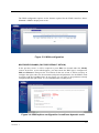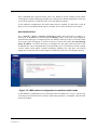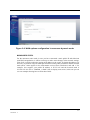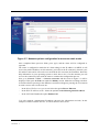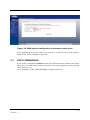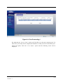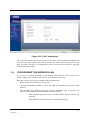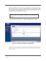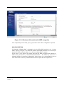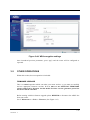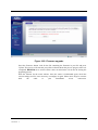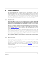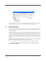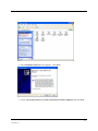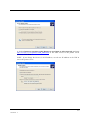
1
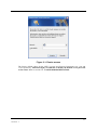
BASIC INSTRUCTIONS TO CONFIGURE ZYXEL P870HNU-51B CPE USING THE WEB INTERFACE Version 1.1 15/06/2011 Index 1 INTRODUCTION .................................................................................................................. 1-1 2 FACTORY DEFAULT SETTINGS ................................................................................... 2-1 3 CPE BASIC OPERATIONS .............................................................................................. 3-1 4 3.1 PASSWORD MODIFICATION .................................................................................... 3-1 3.2 CONFIGURING THE ROUTER.................................................................................. 3-2 3.2.1 MULTIUSER SETTINGS ............................................................................. 3-2 3.2.2 MONOUSER SETTINGS ............................................................................ 3-6 3.3 PORT FORWARDING ................................................................................................ 3-9 3.4 CONFIGURING THE WIRELESS LAN .....................................................................3-11 3.5 OTHERS OPERATIONS........................................................................................... 3-15 USB INTERFACE…………………………………………………………………………….4-1 4.1 3G BACKUP ............................................................................................................... 4-1 4.2 FILE SHARING ........................................................................................................... 4-1 4.3 PRINTER SERVER .................................................................................................... 4-2 Version 1.1 13BBASIC INSTRUCTIONS TO CONFIGURE ZYXEL P870HNU-51B CPE USING THE WEB INTERFACE iii 1 INTRODUCTION This document provides some indications about how to configure the VDSL2 ZyXEL P870HNU-51B, supplied as Telefonica Home Station VDSL2, using the web configurator built-in this device. To configure the broadband service provided by Telefonica, it is recommended to follow the instructions covered in the User’s Guide included in the package. This document is a complementary element to that user’s guide explaining how to configure the router using the VDSL2 router web configurator instead of the configuration wizard included in the router package valid for the Windows OS. It is recommended to use with higher preference this configuration wizard. NOTE: Before starting to use the configuration tools provided directly by the CPE vendor, the ones which Movistar mentions just for reference purposes, we must remind you that Movistar doesn’t provide any kind of technical support for them. This configuration process is based in the access to the router using the PC network adaptor, which will allow using it independently of the operating system. Refer to the help information in your operating system to see how to have a network adaptor properly installed. This document is oriented to advanced users with enough knowledge about networks, routers, operating systems, etc… 1-1 Version 1.1 2 FACTORY DEFAULT SETTINGS The VDSL2 router supplied within the Home Station VDSL2 package is pre-configured by factory default settings in a dynamic multiuser mode, with the DHCP server enabled (this is, it will assign and IP address to those PCs in the internal network configured to obtain the IP settings dynamically) and the wireless LAN interface disabled. To gain the access to the router, it is necessary to have a network adapter installed on the PC, configured to receive an IP address automatically from the DHCP server and with a web explorer configured accordingly with the dynamic multiuser settings. NOTE: The VDSL2 router must be switched on and properly connected to the PC. If you are using a Windows operating system, you can refer to the Ethernet Card and TCP/IP protocol installation guide document and the annex 1 of the Installation Guide for more detailed information. If you are using a Linux or MAC operating system, please refer to the help information in your OS. In case these initial settings could not be useful for your particular case or you find some problems in the broad band service start-up process, you can update or review the configuration using the router web GUI. As the VDSL2 router will be initiated with the LAN IP address 192.168.1.1 and network mask 255.255.255.0, you can check your connectivity with the router (i.e., using a ping command). Once the IP connectivity was successfully checked, you just need to access the http://192.168.1.1 address from your web explorer. NOTE: The screenshots in this document may change in function of the web explorer and the operating system used. 2-1 Version 1.1 FACTORY DEFAULT SETTINGS Figure 2-1: Router access The factory default values for the CPE Username and Password parameters are 1234 and 1234 respectively. Telefónica highly recommends to modify the default access password to the router. Refer to section 3.1 - PASSWORD MODIFICATION. 2-2 Version 1.1 FACTORY DEFAULT SETTINGS Figure 2-2: Web GUI main page In next section you will find how to make some basic operations using the web configurator embedded in this ADSL router. It will be necessary to use the options Network, Security, Advanced and Maintenance that appear on the left side of the menu to complete operations such as: PASSWORD MODIFICATION CONFIGURING THE ROUTER PORT FORWARDING CONFIGURING THE WIRELESS LAN It is not recommended to make any other different operation from these ones defined above using the web configuration. 2-3 Version 1.1 3 BASIC OPERATIONS ON THE ROUTER 3.1 PASSWORD MODIFICATION This is the first operation recommended to be made. Select: Maintenance -> System -> General and you will see next screen: Figure 3-1: Password modification menu Fill in the fields accordingly and keep in mind the key is sensitive to capital and non-capital letters: Old Password: The current password New Password: The new password Retype to confirm: Retype the new password Once filled these boxes, press Apply button. If the operation is completed successfully, the web explorer will be disconnected and it will be necessary to introduce the new password to gain the access back to the router. In case you forget this new password, please refer to the User’s Guide about how to restore factory default settings in your router. 3-1 Version 1.1 BASIC OPERATIONS ON THE ROUTER 3.2 CONFIGURING THE ROUTER If you are going to connect only one PC to your router, a monouser configuration would be enough. In that case, it is recommended to install a firewall and an antivirus software updated and enabled in your PC due to it will be directly connected to the internet. On the other side, if you expected to connect different devices to your router, you must select the multiuser configuration. It is recommended to use a multiuser configuration even though when you´re going to connect only one PC to the internet, due to the fact that it provides higher security and makes it possible to enjoy all the advanced features supported by the router. Additionally to the monouser or multiuser configuration, you must also configure the IP address assignment mode for the VDSL2 router. There are two possibilities about this IP address assignment configuration for a broad band line. Static address assignment: a fixed IP address is assigned to the router for all connections. Dynamic address assignment: the IP address assigned is not always the same, the values provided are the PPPoE session username and password to be used to get the connection. This information appears in the welcome note received by the user at home. They can also be obtained dialing to the phone number 900502010 from the phone line where the broad band line is installed . NOTE: In all next explanations it is considered that the starting point is the factory default settings. If it were necessary, please refer to the CPE User’s Guide to check how to restore factory default settings. 3.2.1 MULTIUSER CONFIGURATIONS In both network address assignments, dynamic (factory default value in the router) and static, some configuration options are common. Initially, it is necessary to configure the router private network (LAN). Select: Network ->LAN to display next screen where you will need to fill in the according values: 3-2 Version 1.1 BASIC OPERATIONS ON THE ROUTER Figure 3-2: Private network address options configuration in multiuser mode If you want, you can change the router IP address (LAN IP->IP Address and IP Subnet Mask) and the DHCP server settings (DHCP Setup -> IP Pool Starting Address and Pool Size) according with the private network desired values. It is not recommended to modify any other parameters. Once introduced previous values, press Apply button and the router will be updated properly. 3-3 Version 1.1 BASIC OPERATIONS ON THE ROUTER The WAN configuration options are the features required for the VDSL2 interface. Select: Network -> WAN to display next screen: Figure 3-3: WAN configuration MULTIUSER DYNAMIC (FACTORY DEFAULT OPTION) In the previous screen, it will be required to press Edit icon located under the Modify section. In the first screen which appears, you must ensure the WAN type is configured as PPP over Ethernet. Then press the Next bottom. In the new screen, it will be necessary to configure the right values for the username and password parameters for the PPPoE client according with the broadband line. In next figure you can refer to the parameters already configured with the right values. It is recommended not to modify them. Figure 3-4: WAN options configuration in multiuser dynamic mode 3-4 Version 1.1 BASIC OPERATIONS ON THE ROUTER Once completed these previous fields, press Next button in all the coming screens which could appear, without modifying anything else, and press the bottom Apply/Save in the last screen of the sequence to make the router saves the changes properly. In the multiuser configurations, the NAT feature must be enabled. To check this, verify in this previous screen that the NAT option is selected. If not, select the Enable NAT option. MULTIUSER STATIC Go to Network -> WAN -> Internet Connection to diplay the screen above in figure 3-3. Now press on the Edit icon located under the Modify section. In the first screen displayed, check that the NAT type is configured as IP over Ethernet. Then press the Next bottom. In the new screen which will appear, it will be necessary to choose the option Use the following Static IP address. It will be necessary to configure here the right values received for the broadband line. Once completed these previous fields, press Next button in all the coming screens which could appear, without modifying anything else, and press the bottom Apply/Save in the last screen of the sequence to make the router saves the changes properly Figure 3-5: WAN options configuration in multiuser static mode In the multiuser configurations, the NAT feature must be enabled. To verify it, check in the according screen from the above sequence where this parameter is configured, that the NAT feature is enabled. 3-5 Version 1.1 BASIC OPERATIONS ON THE ROUTER 3.2.2 MONOUSER CONFIGURATIONS These are not highly recommended settings for this router due to the advanced features supported by this device can not be used. In this case, the PC is the device directly connected to the internet, cause the NAT feature in the router is disable. It is recommended to adopt some safety applications to avoid undesired threats or intrusions in the PC. MONOUSER DYNAMIC In this case, you will need to install a PPPoE client in the PC. If you are using Windows 2000, you can use the client provided in the package or the one supported by the own OS in Windows XP, Vista and 7. If you are using a different operating system, please refer to the help information in your OS to see how to install and use a PPPoE client. If you can not have this PPPoE client in your operating system, you won’t be able to work under this mode. In the configuration process of the PPPoE client installed on the PC you will need to introduce username and password to establish the connection. Additionally it will be required both PC and router to have IP visibility. To do that, both devices must be configured in the same IP private network range. As we take factory default settings as starting point, then the router will have the IP address 192.168.1.1 with network mask 255.255.255.0 and the PC will receive the IP settings through DHCP. If it were necessary, refer to the CPE User’s Guide to see how to restore factory default settings in your router. It is not mandatory, but you can configure the DHCP server settings with the values refered in the Figure 3-2: Private network address configuration options in multiuser mode Go to: Network -> WAN - > Internet connection and the screen in figure 3-3 will be displayed. Next press the Edit icon under the Modify section. In the first screen which appears, ensure that the WAN type is configured as Bridging. Then press the Next bottom. In the next page displayed, press the Apply/Save bottom to make the router can apply the changes properly. 3-6 Version 1.1 BASIC OPERATIONS ON THE ROUTER Figure 3-6: WAN options configuration in monouser dynamic mode MONOUSER STATIC For the monouser static mode, in case you have contracted a static public IP with Movistar with IPoE encapsulation, it will be necessary to make some changes in the network settings. First of all, it will be required to assign an IP address to the router. To obtain this address it is necessary to perform a logical AND operation between the public IP address and the network mask (these values appear in the information received from Telefonica) and add 1. For example, let’s suppose your public IP address is X.X.X.135 and the network mask is 255.255.255.192. Go to: Network -> LAN -> IP to display next screen, in this one you can see one example showing how to fill in these fields. 3-7 Version 1.1 BASIC OPERATIONS ON THE ROUTER Figure 3-7: Network options configuration in monouser static mode Once completed these previous fields, press Apply and the router will be configured as expected. The router is configured to make the PC when asking for the IP address via DHCP, it will receive the public IP address. At this moment, you will lose the IP connectiviy between your PC and the router and it will not be recovered till the PC can renew the IP address. Refer the help information in your operating system to check how to do it. In this moment you will recover the connectivity back with the router to continue the configuration process. Now go to Network -> WAN - > Internet connection and the screen in figure 3-3 will be displayed. Then press the Edit icon under the Modify section. Make the according selections as described below pressing in the different screen that will appear, pressing the Next bottom on each screen to move to the next one. - In the Select WAN service type screen: Select the option IP over Ethernet - In the WAN IP Address screen : Select the option Use the following Static IP address - In the NAT field: Disable the option Enable NAT It is only required a management IP address (shown in the information received). In this example, it will be used the 10.0.0.5, as can be shown in next screen. 3-8 Version 1.1 BASIC OPERATIONS ON THE ROUTER Figure 3-8: WAN options configuration in monouser static mode Once completed these previous fields, press Apply/Save in the last screen of the sequence and the router will be configured as expected. 3.3 PORT FORWARDING If your router is configured in multiuser mode, the NAT feature will be enabled. This feature implies that you could need to forward some ports to use some applications (online gaming, videoconference, etc.). Go to: Network -> NAT -> Port Forwarding to display next screen: 3-9 Version 1.1 BASIC OPERATIONS ON THE ROUTER Figure 3-9: Port Forwarding-1 By deploying the “Service Name” option you´ll be able to see the most common ports. For these ones, you´ll only need to complete the IP addrees to what you want to forward the port. Inside this option, select the “User Define” option and the following screen will be displayed: 3-10 Version 1.1 BASIC OPERATIONS ON THE ROUTER Figure 3-10: Port Forwarding-2 Fill in the data required in the rule for the service name, the port number, IP address and protocol. Press Apply and the rule will be stored in the router. Add as many ports as you need. For safety reasons it is recommended to close all ports not in use, this is, removing them from the above table. 3.4 CONFIGURING THE WIRELESS LAN If you want to configure the ADSL router Wireless LAN interface, keep in mind to use similar settings in the wireless LAN clients to be associated to the router. Basically it will be necessary to configure following parameters: Radio channel to be used by the access point. The network identifier (SSID), it will be the name for identifying the wireless LAN network. The encryption type. Basically there are two main encryption types to provide some privacy to the communications through the wireless interface: WEP (Wired Equivalent Privacy) for Wi-Fi IEEE 802.11b and 802.11g networks. WPA-PSK (Wi-Fi Protected Access / Phase Shift Keying). 3-11 Version 1.1 BASIC OPERATIONS ON THE ROUTER Movistar recommends, for safety reasons, to enable always some encryption in the wireless network. If the network has no 802.11b clients, it is suggested to use WPA encryption. But in the case some 802.11b client could be associated to the router, then it is recommended to use WEP 128-bits encryption. NOTE: The VDSL2 router IP address will depend on the configuration mode (multiuser/monouser , static/dynamic). In this case, we will take, as reference, the 192.168.1.1. To access the wireless LAN settings, go to: Network -> Wireless LAN -> General: Figure 3-11: Wireless LAN options configuration In the previous screen, a generic case of wireless network without security is displayed. To enable any of the security modalities shown before, deploy the “Security Mode” option in the field “Security”: 3-12 Version 1.1 BASIC OPERATIONS ON THE ROUTER Figure 3-12: Security modalities WEP ENCRYPTION In Network -> Wireless LAN -> General option you can define the required parameters (channel, SSID, etc) and the WEP encryption parameters (figure 3-13) by deploying the “Security Mode” option and selecting “WEP”. We strongly recommend you to avoid the No Security option. As a reference, it has been selected the channel 13, ESSID = “zyxelg” and WEP encryption with 128-bits in hexadecimal mode and encryption key 5a303031333439303030303031. Keep on mind the SSID field will differentiate between capital and non-capital letters, and the WEP key length must be of 26 hexadecimal digits. 3-13 Version 1.1 BASIC OPERATIONS ON THE ROUTER Figure 3-13: Wireless LAN enabled with WEP encryption Once completed previous fields, press Apply and the router will be configured as expected. WPA ENCRYPTION In Network -> Wireless LAN -> General select the WPA-PSK modality in the “Security Mode” option (see figure 3.12) and define channel and ESSID parameters. It is necessary to disable the WEP encryption (figure 3-13) before enabling WPA encryption. In the figure 3-14 it appears an example based on this WPA encryption with channel 13, SSID zyxelg and the key "aaaaaaaaaaaaaaaaaaaaaaaaa" . The WPA key must have a minimum length of 8 characters, although for safety reasons it is recommended to have at least 20 characters. This key will differentiate between capital and non-capital letters. 3-14 Version 1.1 BASIC OPERATIONS ON THE ROUTER Figure 3-44: WPA encryption settings Once introduced previous parameters, press Apply and the router will be configured as expected. 3.5 OTHER OPERATIONS Within this section, the next operation is included: FIRMWARE UPGRADE This is a critical operation which can make your router useless, so you must act carefully and use appropiate firmware versions. It is a must to use OFFICIAL FIRMWARE releases approved by Movistar for this model. In other case the guarantee period for this device will be cancelled. Before starting with this firmware upgrade please REMIND to disconnect the ADSL line from your router. Go to: Maintenance -> Tools -> Firmware (See Figure 3.15) 3-15 Version 1.1 BASIC OPERATIONS ON THE ROUTER Figure 3-55: Firmware upgrade Press the Examinar button, look for the file containing the firmware in your PC and press Upload. The process will start and you will be informed about the process progress till it was completed. REMIND not to switch off the router nor disconnect it from the PC during the upgrading process. Wait few minutes for the router reboots. Once the router is initializated again, check the current settings and if it were necessary, reconfigure it again. Please don’t forget to connect back the cable to your Broadband access connection. 3-16 Version 1.1 4 USB INTERFACE This device built-in an USB 2.0 master port which allows end-users to increase the functionality of their access device. By one side, it is possible to connect a 3G modem to enable a backup access to the main DSL interface, through the mobile network; it also allows connect storage USB devices to share files between the users connected in the local network; and finally, it allows as well to act as printer server to allow users connected in the local network to print documents in any printer which could be connected to this USB port. 4.1 3G BACKUP Through the USB port of this device it is possible to connect a 3G modem which could provide a backup line to the VDSL2 main line, to allow end-users could keep on enjoying the internet access according with the price rate contract for the 3G modem, in case of problems with the fixed line. This device is completely compatible with the 3G modems Huawei E1752, Huawei E1752C, ZTE MF110 and ZTE MF190, which are possible to adquire to Movistar. To know if there are new compatible devices, as far as to clarify any other related detail, please check the webpage www.movistar.es/router. The end-user will only need to connect a compatible 3G modem to the router USB port, and in case of problems with the VDSL2 access, it will be automatically redirected to some local pages in the router where it will be required to input the PIN code of the SIM card inserted in the 3G modem to continue surfing in internet through the mobile network according with the prices conditions adquired with the 3G modem. The navegation rate with the 3G modem could depend in function of the coverage area where it were used. 4.2 FILE SHARING It is also possible to connect to this USB port in the router, a external memory disk or a USB memory to be shared in the local network. Once connected, it is possible to access the contents of the external disk or USB memory from any PC in the local network. To do that, it is only necessary to access through the Windows explorer, to the router LAN IP address, by default \\192.168.1.1, to get the access to the shared contents. It will be shown one shared folder with the contents of the external disk or USB memory, to easily surf through them. 4-1 Version 1.1 PRINTER SERVER It will be possible to access only to the primary partitions of the NTFS or FAT32 type of the disks connected, but not possible to access to secondary partitions or other types. 4.3 PRINTER SERVER It will be possible also to connect a printer to the router USB port to share it with the other devices connected to the local network allowing them to print documents in the printer connected to the router. To do that, it would be enough to connect a compatible printer to the router and to have the installation software of that printer on each one of the PCs connected in the local network. It will be just necessary to follow the indications in the installation procedure of the printer software on each PC. If the installation software could require to connect the printer to the PC, keep in mind to ensure that what it will be necessary to ensure is that it is connected to the router. The operating systems supporting this printer server feature are Windows 2000, Windows XP, Windows Vista, Windows 7 and MAC OS X or higher versions. In next case, we will describe how to add manually a printer in the Windows XP OS. 1.- Click Start > Control Panel > Printers and Faxes to open the Printers and Faxes screen. Click Add a Printer. 4-2 Version 1.1 PRINTER SERVER 2.- The Add Printer Wizard screen displays. Click Next. 3.- Select A network printer, or a printer attached to another computer and click Next. 4-3 Version 1.1 PRINTER SERVER 4.- Select Connect to a printer on the Internet or on a home or office network: and enter http://192.168.1.1:631/printers/USB_PRINTER as the URL access to the printer server (Device). Click Next. NOTE : If you change the Device’s LAN IP address, use the new IP address in the URL to access the printer server. 4-4 Version 1.1 PRINTER SERVER 5.- Select the brand of the printer that you want to connect to the router in the Manufacturer list of printers. 6.- Select the printer model from the list of Printers. 7.- If your printer is not displayed in the list of Printers, you can insert the printer driver installation CD/disk or download the driver file to your computer, click Have Disk… and install the new printer driver. 8.- Click Next to continue. 9.- Select Yes and then click the Next button if you want to use this printer as the default printer on your computer. Otherwise select No and then click Next to continue. 4-5 Version 1.1 PRINTER SERVER 10.- The following screen shows your current printer settings. Select Finish to complete adding a new printer. 4-6 Version 1.1