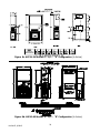
1
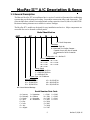
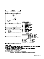
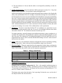
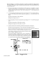
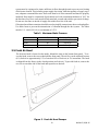
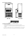
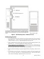
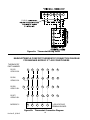
ModPac II™ Vertical Modular Wall-Mount Air Conditioners Installation and Operation Manual MODELS AVP 24-30-36-42-48-60 Supporting Member of 1. Description......................................... 5 2. Installation......................................... 8 3. Start-Up............................................19 4. Troubleshooting.................................20 5. Ratings & Specifications.....................24 6. Maintenance......................................27 7. Warranty...........................................28 Exploded Views & Parts Lists....................29 Manufactured By: Marvair® Division of AIRXCEL®, Inc. P.O. Box 400 • Cordele, Georgia 31010 156 Seedling Drive • Cordele, Georgia 31015 (229) 273-3636 • Fax (229) 273-5154 E-mail: [email protected] • Internet: www.marvair.com The most current version of this manual can be found at www.marvair.com. P/N 81021 9/09-15 supersedes manual dated 2/08-14 How To Use This Manual This manual is intended to be a guide to Marvair's ModPac™ line of vertical air conditioners. It contains installation, troubleshooting, maintenance, warranty, and application information. The information contained in this manual is to be used by the installer as a guide only. This manual does not supersede or circumvent any applicable national or local codes. If you are installing the ModPac™ unit, first read Chapter 1 and scan the entire manual before beginning the installation as described in Chapter 2. Chapter 1 contains general, descriptive information and provides an overview which can speed up the installation process and simplify troubleshooting. If a malfunction occurs, follow this troubleshooting sequence: 1. Make sure you understand how the ModPac™ unit works (Chapters 1 & 3). 2. Identify and correct installation errors (Chapter 2). 3. Refer to the troubleshooting information in Chapter 4. If you are still unable to correct the problem, contact the Factory at 1-800-726-2734 for additional assistance. Please read the following “Important Safety Precautions” before beginning any work. Important Safety Precautions 1. USE CARE when LIFTING or TRANSPORTING equipment. 2. TRANSPORT the UNIT UPRIGHT. Laying it down on its side may cause oil to leave the compressor and breakage or damage to other components. 3. TURN ELECTRICAL POWER OFF AT THE breaker or fuse box BEFORE installing or working on the equipment. LINE VOLTAGES ARE HAZARDOUS or LETHAL. 4. OBSERVE and COMPLY with ALL applicable PLUMBING, ELECTRICAL, and BUILDING CODES and ordinances. 5. SERVICE may be performed ONLY by QUALIFIED and EXPERIENCED PERSONS. * Wear safety goggles when servicing the refrigeration circuit * Beware of hot surfaces on refrigerant circuit components * Beware of sharp edges on sheet metal components * Use care when recovering or adding refrigerant 6. Use COMMON SENSE - BE SAFETY-CONSCIOUS This is the safety alert symbol . When you see this symbol on the ModPac unit and in the instruction manuals be alert to the potential for personal injury. Understand the signal word DANGER, WARNING and CAUTION. These words are used to identify levels of the seriousness of the hazard. Failure to comply will result in death or severe personal injury and/or ! DANGER property damage. Failure to comply could result in death or severe personal injury and/or ! WARNING property damage. Failure to comply could result in minor personal injury and/or property ! CAUTION damage. IMPORTANT is used to point out helpful suggestions that will result in improved installation, reliability or operation. ModPac II, 9/09-15 Specifications subject to change without notice. © 9/09 Marvair® WARNING • If the information in these instructions are not followed exactly, a fire may result causing property damage, personal injury or loss of life. • Read all instructions carefully prior to beginning the installation. Do not begin installation if you do not understand any of the instructions. • Improper installation, adjustment, alteration, service or maintenance can cause property damage, personal injury or loss of life. • Installation and service must be performed by a qualified installer or service agency in accordance with these instructions and in compliance with all codes and requirements of authorities having jurisdiction. INSTALLER: Affix the instructions on the inside of the building adjacent to the thermostat. END USER: Retain these instructions for future reference. Table of Contents ModPac II™ A/C Description & Specs 1.1 General Description........................................................................................................................ 5 1.2 General Operation.......................................................................................................................... 6 1.3 Electrical Diagrams........................................................................................................................ 6 Installation 2.1 2.2 2.3 2.4 2.5 2.6 2.7 2.8 2.9 Equipment Inspection..................................................................................................................... 8 Installation Requirements............................................................................................................... 8 Installation Materials.................................................................................................................... 11 Porting and Duct Work................................................................................................................. 12 Fresh Air Hood Installation.......................................................................................................... 13 "V" Damper Installation............................................................................................................... 14 Bracket Installation ..................................................................................................................... 14 Mounting the Unit........................................................................................................................ 15 Electrical Connections.................................................................................................................. 16 Start-Up 3.1 Check-Out of Cooling Cycle . ......................................................................................................19 3.2 Check-Out of Heating Cycle.........................................................................................................19 Troubleshooting 4.1 4.2 4.3 4.4 Overview.......................................................................................................................................20 Failure Symptoms Guide...............................................................................................................21 Compressor Troubleshooting........................................................................................................22 Electric Heat Controls...................................................................................................................23 Ratings & Specifications 5.1 Ratings & Specifications ..............................................................................................................24 5.2 Dimensional Data..........................................................................................................................25 ModPac II, 9/09-15 Periodic Maintenance Requirements 6.1 Scheduled Maintenance................................................................................................................ 27 Warranty Information 7.1 Warranty Statement.......................................................................................................................28 Exploded Views & Parts Lists..............................................................................................................29 Illustrations Figure 1. Figure 2. Figure 3. Figure 4. Figure 5. Figure 6a. Figure 6b. Figure 7. Figure 8a. Figure 8b. Figure 8c. Figure 8d. Tables Table 1. Table 2. Table 3. Table 4. Table 5. Typical Electric Schematic ........................................................................................... 7 Damper Air Path.......................................................................................................... 10 Fresh Air Hood Adjustment......................................................................................... 13 "V" Damper Installation.............................................................................................. 14 Wall Mounting Detail - AVP24-36............................................................................... 15 Thermostat Wiring Detail............................................................................................ 18 Thermostat Connection Diagram................................................................................. 18 Typical Configuration for Single Element Heater....................................................... 23 ModPac II™ A/C Dimensions - AVP24-36 "N" Config............................................... 25 ModPac II™ A/C Dimensions - AVP42-60 "N" Config................................................ 25 ModPac II™ A/C Dimensions - AVP24-36 "B" Config............................................... 26 ModPac II™ A/C Dimensions - AVP42-60 "B" Config................................................ 26 Voltage Limitations.........................................................................................................9 Maximum Static Pressure.............................................................................................13 CFM @ ESP..................................................................................................................24 Ship Weight...................................................................................................................24 Filter Size......................................................................................................................24 ModPac II, 9/09-15 ModPac II™ A/C Description & Specs 1.1General Description The Marvair ModPac II™ air conditioner line is a series of vertical wall-mounted air conditioning systems that provide heating and cooling for modular construction offices and classrooms. The series includes three cabinet sizes and nominal cooling capacities from 24,000 to 56,000 BTUH. Resistance heating elements are available in various wattages. The ModPac II™ models are designed for easy installation and service. Major components are accessible for service beneath external panels. Model Identification AVP • AC • • M • • U = Scroll Compressor Ventilation N = 0-15% Fresh Air B =Motorized Two Position Damper Capable of up to 450 cfm of outside air (maximum of 40% of rated air flow) Configuration - M = ModPac II Electric Heat 000 040 050 080 = = = = No Heat 090 = 9 kW 4 kW 100 = 10 kW 5 kW 150 = 15 kW 8 kW Power Supply A = 208/230V,1ø,60 Hz C = 208/230V,3ø,60 Hz D = 460V,3ø,60 Hz System Type - Air Conditioner Nominal Cooling 24 = 24,000 BTUH 42 = 42,500 BTUH 30 = 29,400 BTUH 48 = 48,000 BTUH 36 = 36,000 BTUH 60 = 56,000 BTUH Air Source Vertical Package Serial Number Date Code A = January J = September B = February K = October C = March L = November D = April M = December E = May F = June G = July H = August L = 2000 M = 2001 N = 2002 P = 2003 R = 2004 S = 2005 T = 2006 U = 2007 V = 2008 Y = 2009 Z = 2010 A = 2011 ModPac II, 9/09-15 1.2General Operation Refrigerant Cycle (Cooling Mode) The ModPac II™ A/C uses R-22 refrigerant in a conventional vapor-compression refrigeration cycle to transfer heat from air in an enclosed space to the outside. A double blower assembly blows indoor air across the evaporator. Liquid refrigerant passing through the evaporator is boiled into gas by heat removed from the air. The warmed refrigerant gas enters the compressor where its temperature and pressure are increased. The hot refrigerant gas condenses to liquid as heat is transferred to outdoor air blown across the condenser by the condenser fan. Liquid refrigerant is metered into the evaporator through capillary tubes to repeat the cycle. Heating Mode A wall-mounted thermostat controls the heating cycle of models which incorporate resistance heating elements. On a call for heat, the thermostat closes the heat relay to energize the indoor fan and the resistance elements. Ventilation Options • Manual damper capable of up to 15% of rated airflow of outside air; field adjustable, no pressure relief. (Standard - Ventilation Configuration N) • Motorized, two position damper (open and closed) capable of 0 to 450 cfm (maximum of 40% of rated airflow) of outside air; includes pressure relief. A 24-volt actuated motor controls the damper from an external input such as: a time clock, CO2 sensor, energy management system or manual switch. (Optional - Ventilation Configuration B) • Manual damper capable of 15 to 450 cfm of outside air (up to a maximum of 40% of rated air flow). No pressure relief. An external, field installed front panel replaces standard front panel. (Optional - “V” Damper ) 1.3Electrical Diagrams The compressor incorporates an internal PTC crankcase heater that functions as long as primary power is available. The heater drives liquid refrigerant from the crankcase and prevents loss of lubrication caused by oil dilution. Power must be applied to the unit for 24 hours before starting the compressor. The compressor is energized with a contactor controlled by a 24 VAC pilot signal (see Figure 1). The evaporator blower motor is cycled by the blower time delay relay. IMPORTANT NOTE: The ModPac II™ A/C models incorporate a 90 second purge cycle that runs the evaporator blower after the thermostat is satisfied. ModPac II, 9/09-15 Figure 1. Typical Electric Schematic for Models AVP24-60 ModPac II, 9/09-15 Installation WARNING Failure to observe and follow Warnings and Cautions and these Instructions could result in death, bodily injury or property damage. Read this manual and follow its instructions and adhere to all Cautions and Warnings in the manual and on the Marvair unit. 2.1Equipment Inspection Concealed Damage Inspect all cartons and packages upon receipt for damage in transit. Remove cartons and check for concealed damage. Important: keep the unit upright at all times. Remove access panels and examine component parts. (Note: the bottom brackets for Models AVP24-60 are stored in the condenser air compartment. Remove them before replacing the side screen). Inspect refrigerant circuit for fractures or breaks. The presence of refrigerant oil usually indicates a rupture. If damage is apparent, immediately file a claim with the freight carrier. Units that have been turned on their sides or tops may have concealed damage to compressor motor mounts or to the oil system. If the unit is not upright, immediately file a claim for concealed damages and follow these steps: 1. Set unit upright and allow to stand for 24 hours with primary power turned on. 2. Attempt to start the compressor after 24 hours. 3. If the compressor will not start, makes excessive noise, or will not pump, return the unit to the freight carrier. 2.2Installation Requirements General 1. Inspect unit for completeness. Check for missing parts (e.g. hardware). Refer to the installation kit information in section 2.3. 2. Remove access panels and check for loose wires. Tighten screw connections if necessary. 3. Complete and mail the warranty registration card. You must consider all of the following when choosing the installation site: 1. Noise. Install the unit so that the least amount of noise will be transmitted to inhabited spaces. 2. Condensate Drainage. Condensate produced during operation must be discharged to a suitable drain. 3. Placement. A) Place the unit in a shaded area, if possible. B) Install it above ground for protection against flooding. ModPac II, 9/09-15 C) The unit exhausts air. Be sure that the airflow is not impeded by shrubbery or other obstructions. 4. Airflow Requirements. Note the minimum CFM requirements (section 2.4). Keep duct lengths as short as possible. Do not obstruct airflow through the unit. Applications using duct work should be designed and installed in accordance with all applicable safety codes and standards. Marvair® strongly recommends referring to the current edition of the National Fire Protection Association Standards 90A and 90B before designing and installing duct work. The duct system must be engineered to insure sufficient air flow through the unit to prevent over-heating of the heater element. This includes proper supply duct sizing, sufficient quantity of supply registers, and adequate return and filter areas. Duct work must be of correct material and must be properly insulated. Duct work must be constructed of galvanized steel with a minimum thickness of .019". Duct work must be firmly attached, secured, and sealed to prevent air leakage. See section 2.4 for additional duct work requirements. 5. Clearances. Clearances around the ModPac II™ air conditioner are required for service access and for proper operation of the unit. For service, the minimum clearance from either side and the front is 30". The minimum clearance from the top is 24". For proper operation, especially during warm ambient temperatures, proper condenser air is essential. The condenser air is brought into the condenser compartment through grilles on each side of the unit. The condenser air is discharged through the coil at the front of the unit. It is important that the inlet air not be restricted and that the discharge air not be "short circuited" back into the side intakes. 6. Codes. Make sure your installation conforms to all applicable electrical, plumbing, building, and municipal codes. Some codes may limit installation to single story structures. 7. Electrical Supply. The power supply must have the appropriate voltage, phase, and ampacity for the model selected. Voltage must be maintained above minimum specified values listed below. Refer to the data sticker on the unit for ampacity requirements. Table 1. Voltage Limitations Electrical Rating Designations* Nominal Voltage Phase and Hertz Minimum Voltage Maximum Voltage A C D 208/230 1/60 197 253 208/230 3/60 187 253 460 3/60 414 506 *Letters refer to the system electrical rating in the model number identification. Refer to page 5. 8. Ventilation System Set-Up: Manual Fresh Air System (Configuration N). This is the standard ventilation system in the ModPac™ air conditioner. Fresh air ventilation by means of a damper can provide up to 15% of rated air flow of outside air. The damper has four positions corresponding to 0, 5, 10 and 15% of rated air flow of outside air. The damper only opens when the indoor fan is operating. Position the screw on the side of the damper hood for the desired air flow. ModPac II, 9/09-15 Motorized Damper - 0 to 450 cfm of Outside Air and Pressure Relief (Configuration B) The settings of the damper require a balometer and a thermometer for measuring internal and external temperatures. a. Measure the total supply air with a balometer. If the supply air is controlled by a manual fan speed controller, make certain that the air flow is in accordance with Table 3, Air Flow (CFM) at Various Static Pressures. This CFM is referred to as "C" in the illustration and equation below. b. "A" is the quantity of outside air expressed as a percentage of "C". For example, if the supply air is 1,220 CFM and 300 CFM of outside air is required, "A" is 25% (300 CFM/1,220 CFM) Measure the temperature of the outside air. Multiply the temperature by "A". c. "B" is the quantity of return air expressed as a percentage of "C". "A" and "B" must equal 100%. Measure the temperature of the indoor return air. Multiply the temperature of the indoor air by "B". d. Calculate what the Tmix should be with the desired quantity of outside air. Measure the actual temperature of Tmix at the inlet to the supply air blower. Adjust the damper blade until the measured value of the Tmix equals the calculated or desired value of Tmix. To adjust the damper, loosen the set screw on the damper rod and move the rod as required. When the adjustment is complete, tighten the set screw. The motorized damper, Configuration B, can be controlled by an optional relay that allows additional external control with a choice of 24, 120 or 240V coils to regulate fresh air ventilation in response to a control located remote from the ModPac™ air conditioner. Figure 2. Damper Air Path ModPac II, 9/09-15 10 2.3Installation Materials Installation Kits All ModPac II™ A/C units have built-in side flanges that function as side brackets. All models require and are shipped with a bottom mounting bracket. There is also an air intake hood factory installed behind the lower front panel. Standard Kit Components - Models AVP24-60: 1. One 12 Ga. "L"-shaped bottom bracket Accessories: The package may include other factory-supplied items (optional) as follows: Part #Description 50121 Digital thermostat. 1 stage heat, 1 stage cool. Non-programmable. Fan switch:Auto & On. Manual changeover system switch: Cool-Off-Heat. Low temperature protection. °F or °C. 50123 Digital thermostat. 1 stage heat, 1 stage cool. 7 day programmable. Fan switch: Auto & On. Auto-change over. Keypad lockout. Non-volatile program memory. 80674 VPG-20S, 20 x 8" Adjustable, Aluminum Double Deflection Supply Grille for AVP 24 80675 VPG-30S, 28 x 8" Adjustable, Aluminum, Double Deflection Supply Grille for AVP 30-36 80676 VPG -40S, 30 x 10" Adjustable, Aluminum, Double Deflection Supply Grille for AVP 42-48-60 80677 VPG -20R, 20 x 12" Aluminum Return Grille for AVP 24 80678 VPG -30R, 28 x 14" Aluminum Return Grille for AVP 30-36 80679 VPG -40R, 30 x 16" Aluminum Return Grille for AVP 42-48-60 80671* VPG -20RF, 20 x 12" Aluminum Return Filter Grille for AVP 24 80672* VPG -30RF, 28 x 14" Aluminum Return Filter Grille for AVP 30-36 80673* VPG -40RF, 30 x 16" Aluminum Return Filter Grille for AVP 42-48-60 *Use when outside air is not required. Remove and discard filter in unit. Additional Items Needed: Additional hardware and miscellaneous supplies (not furnished by Marvair®) are needed for installation. For example, the list below contains approximate quantities of items typically needed for mounting a unit on a wood frame wall structure. Concrete or fiberglass structures have different requirements. 10 3/8" mounting bolts for side brackets. The length needed is typically the wall thickness plus one inch. 20 3/8" washers 10 3/8" hex nuts 6 3/8" x 2-1/2" lag screws for bottom bracket • Silicone Sealer to seal around cracks and openings • 4-conductor low voltage multi-colored wire cable (i.e. thermostat wire) 11 ModPac II, 9/09-15 Appropriate electrical supplies such as conduit, electrical boxes, fittings, wire connectors, etc. • High voltage wire, sized to handle the MCA (minimum circuit ampacity) listed on the data plate. • Over-Current Protection Device sized in accordance with the MFS (maximum fuse size) listed on the unit data plate. Duct materials usually are also needed in addition to the mounting hardware. To save time, design the duct work before mounting the unit. • Warning FIRE HAZARD Improper adjustment, alteration, service, maintenance or installation could cause serious injury, death and/or property damage. Installation or repairs made by unqualified persons could result in hazards to you and others. Installation MUST conform with local codes or, in the absence of local codes, with codes of all governmental authorities have jurisdiction. The information contained in this manual is intended for use by a qualified service agency that is experienced in such work, is familiar with all precautions and safety procedures required in such work, and is equipped with the proper tools and test instruments. 2.4Porting and Duct Work General Information Note: The following instructions are for general guidance only. Due to the wide variety of installation possibilities, specific instructions will not be given. When in doubt, follow standard and accepted installation practices, or contact Marvair® for additional assistance. Wall Openings and Duct Clearance Measure the dimensions of the supply and return openings on the ModPac II™ air conditioner . Warning Cut the supply opening in the exterior wall for the supply and return. IMPORTANT: All units must have one inch clearance on all four sides of the supply outlet duct flange on the unit. The one inch clearance must extend on all sides of the supply duct for the first three feet from the unit. Minimum Airflow Requirements Warning The duct system must be engineered to assure sufficient air flow through the ModPac II™ A/C, even under adverse conditions such as dirty filters, etc. Use Table 2 below and Table 3 - CFM at External Static Pressure (Wet Coil) in section 5.1. Ducting Extensions should be cut flush with the inside wall for applications without duct work. Applications using duct work should be designed and installed in accordance with the current edition of the National Fire Protection Association codes and standards 90A and 90B. The duct ModPac II, 9/09-15 12 system must be engineered to insure sufficient air flow through the unit to prevent over-heating of the heater element. This includes proper supply duct sizing, sufficient quantity of supply registers, adequate return and filter area. Duct work must be of correct material and must be properly insulated. Duct must be constructed of galvanized steel with a minimum thickness of .019" for the first three feet. Duct work must be firmly attached, secured and sealed to prevent air leakage. Do not use duct liner on inside of supply duct within four feet of the unit. Galvanized metal duct extensions should be used to simplify connections to duct work and grilles. Use fabric boots to prevent the transmission of vibration through the duct system. The fabric must be U.L. rated (UL-181) to a minimum of 197°F. Table 2. Maximum Static Pressure Basic Model Maximum Total Static Minimum Filter Area 24 .40 2.25 sq. ft. 30/36 .40 3.00 sq. ft. 42/48/60 .50 3.90 sq. ft. 2.5Fresh Air Hood The fresh air hood is located on the inside, behind the slots on the bottom front panel. To access the hood, remove the screws that hold the front panel. The air flow can be adjusted from no (0%) fresh air to approximately 15% of rated air flow of fresh air, in 5% increments. The hood is shipped from the factory in the closed position (no fresh air). To provide fresh air, remove the two screws on either side of the hood and reposition as desired.. Figure 3. Fresh Air Hood Damper 13 ModPac II, 9/09-15 2.6"V" Damper Installation ® Figure 4. "V" Damper Installation 2.7Bracket Installation 1. The ModPac II™ air conditioners have built-in mounting flanges. See Figure 5. 2. Refer to Figure 5. Attach the bottom support bracket to the wall using appropriate 3/8" diameter hardware. For example, on wooden structures, use 3/8 x 2-1/2 inch all-thread lag screws. The screws must penetrate the center of the wall stud. Drill a pilot hole in the stud to prevent it from splitting. ModPac II, 9/09-15 14 For units with electric heat, a one inch clearance is required around the duct extensions. The duct extensions must be constructed of galvanized steel with a minimum thickness of .019” as per the NFPA standards 90A & 90B. Figure 5. Wall Mounting Detail - Models AVP24-60 2.8Mounting the Unit 1. For wiring into the back of unit, locate the lower of the two knock-outs on the wall side of the ModPac II™ A/C. Drill a one inch hole in the shelter wall to match this opening. Allow sufficient clearance to run 3/4" conduit through the hole and to the unit. 2. Apply a generous bead of silicone sealer on the wall side of the mounting brackets on the ModPac II™ A/C. Circle the mounting holes with the silicone bead. 3. Using an appropriate and safe lifting device, set the ModPac II™ A/C on the bottom support bracket mounted on the wall. You must stabilize the unit on the bracket with the lifting device or by some other means - the bracket alone is not sufficient. 4. Make sure that the duct flanges are properly aligned with the wall opening. Adjust as necessary. 5. Note the holes in each side bracket. Using the holes for guides, drill holes through the wall with a 3/8" drill bit. Insert the 3/8 x 5" bolts through the brackets. Install nuts and washers on the inside of the building. Tighten the bolts to secure the unit. 15 ModPac II, 9/09-15 6. Apply a bead of silicone where the flashing and side brackets contact the unit and the building wall. 7. Fasten the flashing to the unit casing and the building wall using #10 x 1/2 inch sheet metal screws. 8. On the inside of the building, install the wall sleeves in the supply and return air openings. The sleeves may be trimmed to fit flush with the inside wall. For units with electric heat, a one inch clearance is required around the duct extensions. The duct extensions must be constructed of galvanized steel with a minimum thickness of .019” as per the NFPA standards 90A & 90B. 9. Check the fit of each sleeve to its mating flange for possible air leaks. Apply silicone sealer to close any gaps. Install the air return and supply grilles. WARNING ELECTRICAL SHOCK HAZARD Failure to follow safety warnings exactly could result in serious injury, death, and/or property damage. Turn off electrical power at fuse box or service panel BEFORE making any electrical connections and ensure a proper ground connection is made before connecting line voltage. 2.9Electrical Connections IMPORTANT! All electrical work must meet the requirements of local codes and ordinances. Work should be done only by qualified persons. CAUTION ModPac II™ A/C units incorporate an internal crankcase heater for compressor protection. The crankcase heater must be energized for at least 24 hours prior to starting the compressor. Scroll compressors are standard on the ModPac II™ models AVP42,48 and 60. They may be ordered as an option on the models AVP24, 30 and 36. Scroll compressors, like several other types of compressors, will only compress in one rotational direction. The direction of rotation is not an issue with single-phase compressors since they will always start and run in the proper direction. However, three phase compressors will rotate in either direction depending upon phasing of power. Since there is a 50-50 chance of connecting power in such a way as to cause rotation in the reverse direction, it is imperative to confirm that the compressor is rotating in the proper direction at the initial field start-up of the system. Verification of proper rotation is made by observing that the suction pressure drops and the discharge pressure rises when the compressor is energized. An alternate method of verification for self contained system with small critical refrigerant charges, where the installation of gauges may be objectionable, can be made by monitoring the temperature of the refrigerant lines at the compressor. The temperature should rise on the discharge line while the suction line temperature decreases. Reverse rotation also results in a substantially reduced current draw when compared to tabulated values. There is no negative impact on durability caused by operating three phase compressors in the reversed direction for a short duration of time, usually defined as less than one hour. However, ModPac II, 9/09-15 16 after several minutes of operation the compressor's internal protector will trip. The compressor will then cycle on the protector until the phasing is corrected. Reverse operation for longer than one hour may have a negative impact on the bearings. Failure to ensure proper rotation will void the warranty of the compressor. High Voltage Wiring The power supply should have the proper voltage, phase, and ampacity for the selected model. 1. Refer to electrical data stamped on the unit rating plate for field wiring requirements. The electrical data lists heater sizes, fuse sizes, and wire sizes for all models. Also shown are the number for field power circuits required for the various modes with the electric heaters. Each unit is marked with a “Minimum Circuit Ampacity”. This means that the field wiring used must be sized to carry that amount of current. Use “Copper Conductions Only”. Refer to the National Electrical Code for complete current carrying capacity data on the various insulation grades of wiring materials. CAUTION Note: Power supply service must be within allowable range (+10% - 5%) of rated voltage stamped on the unit rating plate. To operate nominal 230/208V unit at 208V, change the transformer line tap from 240V to 208V following the instruction on wiring label in unit. 2. Connect the wires to the input side of the internal breaker (L1 & L2 for single-phase units; L1, L2, & L3 for three phase models). 3. Install the ground wire on the ground lug. 4. Units designed to operate on 460V have a step down transformer for 230V motors. Low Voltage Wiring 1. Pull the low voltage wiring (e.g., 18 gauge 4-conductor Class 2 thermostat wire) from the ModPac II™ A/C into the thermostat / sub-base assembly. 2. Mount the sub-base on a level plane. Use a spirit level. Connect the thermostat wire to the ModPac II™ A/C terminal board and the thermostat as shown in Figure 6. 3. Attach the thermostat assembly to the sub-base. Check the heat anticipator settings - it should read .40. THE INTERNAL TRANSFORMER IS NOT DESIGNED TO POWER OTHER EXTERNAL DEVICES. 17 ModPac II, 9/09-15 5 FIVE (5) Figure 6a. Thermostat Wiring Detail MARVAIR®/SIMPLE COMFORT THERMOSTAT CONNECTION DIAGRAM FOR MARVAIR MODPAC II™ AIR CONDITIONERS THERMOSTAT PART NUMBER 50121/ SC2010-SL R G Y W C O B 50124/ SC3001-SL Rc RH G Y W C O B 50123/ SC5011-SL Rc RH G Y W C O B 50107/ SC5811-SL R G Y1 W1 C Y2 W2 MODPAC II R G Y W C LOW VOLTAGE TERMINAL BOARD O/B Figure 6b. Thermostat Connection Diagram ModPac II, 9/09-15 18 Start-Up Important: If your unit has a crankcase heater be sure that the crankcase heater has been energized for at least 24 hours prior to start-up of the unit. Double check all electrical connections before applying power. Various thermostats can be used to control the air conditioner. The thermostat may have a fan switch with an Automatic and On positions, a system switch with Heat, Cool, and Off positions. The spec sheets have detailed description of the various Marvair® thermostats. Since other thermostats or remote control systems may be used, the following procedures should be viewed as guidelines for standard thermostats with system and fan switches. 3.1Check-Out of Cooling Cycle Procedure: 1. Set the cooling temperature on the wall thermostat to a point higher than the ambient temperature. Set the heating temperature to a temperature that is lower than the ambient. 2. Set the thermostat system switch in the AUTO position. Nothing should operate at this time. 3. Slowly lower the thermostat's cooling temperature until the switch closes. The indoor fan should operate. Once the indoor fan turns on, allow approximately three minutes for the compressor to start. Note that the outdoor fan may not come on immediately, because it is cycled by refrigerant pressures. Alternately, when outdoor conditions are lower than the set point, a source of heat such as a hair dryer can be directed on the air temperature sensor to simulate warmer conditions, which will bring on mechanical cooling and start the compressor. IMPORTANT 4. To stop cooling, slowly raise the thermostat cooling to a temperature higher than the ambient. If the unit fails to operate, refer to the troubleshooting information in Chapter 4. Follow the same procedure for additional units. NOTE: Blower Time Delay Relay (BTR) allows the indoor fan to run for approximately 90 seconds after the compressor is off. This operation provides a small improvement in system efficiency. 3.2Check-Out of Heating Cycle Procedure: (Applies only to units with resistance elements.) 1. Raise the heating temperature to a setting which is higher than the ambient temperature. The fan and electric heat should immediately cycle on. 2. Move the system switch to the "OFF" position. All functions should stop. 19 ModPac II, 9/09-15 Troubleshooting 4.1Overview A comprehensive understanding of the operation of the ModPac II™ air conditioner is a prerequisite to troubleshooting. Please read the Chapter 1 for basic information about the unit. Marvair® ModPac II™ air conditioners are thoroughly tested before they are shipped from the factory. Of course, it is possible that a defect may escape undetected, or damage may have occurred during transportation. However, the great majority of problems result from installation errors. If you experience difficulties with the ModPac II™ A/C, please review the installation steps in Chapter 2. Much time can be saved by taking a thoughtful and orderly approach to troubleshooting. Start with a visual check - are there loose wires, crimped tubing, missing parts, etc.? Begin deeper analysis only after making this initial inspection. The troubleshooting information in this manual is basic. The troubleshooting section contains problem / solution charts for general problems, followed by a compressor section. Not every problem can be anticipated. If you discover a problem that is not covered in this manual, we would be very grateful if you would bring it to the attention of our service department for incorporation in future revisions. As always, please exercise caution and good judgement when servicing the ModPac II™ A/C. Use only safe and proven service techniques. Use safety goggles when servicing the refrigeration circuit. warning The refrigerant circuit has hot surfaces, and the electrical voltages inside of the unit may be hazardous or lethal. SERVICE SHOULD BE PERFORMED ONLY BY QUALIFIED AND EXPERIENCED PERSONS. ModPac II, 9/09-15 20 4.2 Failure Symptoms Guide PROBLEM/SYMPTOM A. Unit does not run. LIKELY CAUSE(S) CORRECTION 1. Power supply problem. 1. Check power supply for adequate phase and voltage. Check wiring to unit and external breakers or fuses. 2. Blown fuse or breaker. 2. Check circuit protection devices for continuity. 3. Shut off by external thermostat or thermostat is defective. 3. Check operation of wall-mounted thermostat. 4. Internal component or connection failure. 4. Check for loose wiring. Check components for failure B. Unit runs for long periods or continuously; cooling is insufficient. C. Unit cycles on Compressor Overload D. Unit blows fuses or trips circuit breaker. E. Water on floor near unit or leaking from cabinet. F. No space heating or reduced heating (units equipped with resistance elements) 1. Unit undersized for job. 1. Add additional units for greater capacity. 2. Loss of refrigerant. 2. Check for proper charge and possible leak. 3. Component failure. 3. Check internal components, especially compressor for proper operation. 4. Dirty filter or reduced airflow. 4. Check air filter(s). Check blower operation. Remove airflow restriction. 1. Loss or restriction of airflow. 1. Check blower assembly for proper operation. Look for airflow restrictions, e.g., the air filter. Check blower motor and condenser fan. 2. Restriction in refrigerant circuit. 2. Check for blockage or restriction, especially filter drier and capillary tube assembly. 3. Refrigerant overcharge (following field service) 3. Evacuate and recharge to factory specifications. 1. Inadequate circuit ampacity. 1. Note electrical requirements in Chapter 2 and correct as necessary. 2. Short, loose, or improper connection in field wiring. 2. Check field wiring for errors. 3. Internal short circuit. Loose or improper connection(s) in unit. 3. Check wiring in unit. See wiring and schematic diagrams. Test components (especially the compressor) for shorts. 4. Excessively high or low supply voltage or phase loss (3ø only). 4. Note voltage range limitations specific to the compressor troubleshooting section. 1. Obstruction in condensate line. 1. Check for clog or restriction. 2. Obstruction or leak in condensate pan. 2. Check pan for leak or blockage. 3. Unit is not level. 3. Level unit. 1. Defective heating element(s). 1. Check resistance element(s) for continuity. 2. Thermal limit open. 2. Check continuity across thermal limit switch. 3. Defective heater contactor. 3. Check for proper operation. 21 ModPac II, 9/09-15 4.3Compressor Troubleshooting NOTE: It is important to rule out other component failures before condemning the compressor. The following electrical tests will aid diagnosis: 1. Start-Up Voltage: Measure the voltage at the compressor terminals during start-up. The voltage must exceed the minimum shown in Table 4, section 2.2, or compressor failure is likely. A low voltage condition must be corrected. 2. Running Amperage: Connect a clamp-on type ammeter to the (common) lead to the compressor. Turn on the supply voltage and energize the unit. The compressor will initially draw high amperage; it should soon drop to the RLA value or less. If the amperage stays high, check the motor winding resistances. NOTE: Feel the top of the compressor to see if it has overheated. If it is hot, the internal overload may be open. You may have to wait several hours for it to reset. 3. Motor Winding Resistances: Using a digital volt-ohm meter (VOM), measure the resistance across the compressor windings as shown on the following page: C SINGLE PHASE R2 S R1 R3 R THREE PHASE R3 > R2 > R1 R3 = R2 + R1 T1 R2 T2 R1 R3 R3 = R2 = R1 T3 Resistance can be measured as shown above. Any deviation from above values could indicate a defective compressor. 4. High Voltage/Insulation Test: Test internal leakage with a megohmeter. Attach one lead to the compressor case on a bare metal tube and to each compressor terminal to test the motor windings. A short circuit at high voltages indicates a motor defect. Do not do this test under vacuum. 5. On single phase models, check the capacitor by substitution. ModPac II, 9/09-15 22 4.4Electric Heat Controls Figure 7. Typical Configuration for Single Element Heater The electric heater assembly can have up to three individual heating elements. Each individual heating element is protected against overheating by its own dual function thermal cut-out switch. Additionally, a separate single function thermal cut-out switch protects the entire heater assembly. The dual function thermal cut-out switch (P/N 70006) is composed of two independent line voltage snap-disc temperature switches mounted in a single enclosure. One of these switches is an automatic reset device which cycles off at approximately 145°F and back on at approximately 115°F. Should this switch fail to open, the second switch will open the circuit if the temperature continues to increase. This second switch does not reset. If it opens (breaks the line voltage circuit to the heater assembly) the switch will have to be replaced by qualified service personnel after the source of the overheat problem is resolved. In addition to the thermal cut-out switch described above, there is a single function thermal cut-out switch (P/N 70005) mounted on the heater frame. This switch controls the 24V AC control current to the heater contactor(s) which powers all the heating elements. This single function thermal cutout switch operates totally independent of the dual thermal cut-out switch described above. If the single function switch senses an overheat situation, it opens the control circuit and turns off all of the installed heating elements via the heater contactor(s). Because this switch controls the heater contactor(s), only one switch is required to disconnect power from the contactor(s), regardless of the number of heater elements. This single function switch is also non-resettable, and must be replaced by qualified service personnel after the source of the overheat problem is resolved. This switch would typically open if both elements of the dual thermal cut-out switches failed. 23 ModPac II, 9/09-15 Ratings and Specifications 5.1Ratings & Specifications Table 1. CFM @ ESP (Wet Coil) MODEL 24 0.10 0.20 0.30 0.40 0.50 860 810 670 --- --- 30 1100 1000 920 810 --- 36 1310 1220 1150 1060 --- 42 --- 1650 1520 1450 1360 48 --- 1900 1760 1700 1620 60 --1900 1760 CFM = Cubic Feet per Minute - Indoor Air Flow ESP = External Static Pressure in Inches WG 1700 1620 Table 2. Ship Weight (Lbs.) MODEL "N" Configuration 24 30/36 42 48 60 270 350 485 510 522 "B" Configuration 286 365 527 552 565 Table 3. Filter Size (In Inches) MODEL FILTER SIZE ModPac II, 9/09-15 24 30/36 42/48/60 16 x 25 x 1 16 x 30 x 1 22 x 36-1/2 x 1 24 5.2Dimensional Data DIMENSIONS AVPA 24-36 N DAMPER AVPA 24 AVPA 30-36 Figure 8a. AVP24-36 ModPac II™ A/C - "N" Configuration (In Inches) Figure 8b. AVP42-60 ModPac II™ A/C - "N" Configuration (In Inches) 25 ModPac II, 9/09-15 AVPA 24 AVPA 30-36 Figure 8c. AVP24-36 ModPac II™ A/C - "B" Configuration (In Inches) Figure 8d. AVP42-60 ModPac II™ A/C - "B" Configuration (In Inches) ModPac II, 9/09-15 26 Maintenance 6.1Scheduled Maintenance Marvair® strongly recommends that the air conditioner be serviced a minimum of twice a year – once prior to the heating season and once prior to the cooling season. At this time the filters, evaporator coil, condenser coil, the cabinet, and condensate drains should be serviced as described below. Also at this time, the air conditioner should be operated in the cooling and heating cycles as described in Chapter 3, Start-Up. In addition to this seasonal check-out, the ModPac™ A/C should be maintained as follows: Air Filter Replace the air filter whenever it is visibly dirty. Evaporator If the evaporator becomes clogged or dirty, it may be cleaned by careful vacuuming or with a commercial evaporator cleaning spray. DO NOT use a solvent containing bleach, acetone, or flammable substances. Turn power off before cleaning. Be careful not to wet any of the electrical components. Be sure the unit has dried before restarting. Condenser Periodically inspect the outdoor condenser coil and the cabinet air reliefs for dirt or obstructions. Remove foreign objects such as leaves, paper, etc. If the condenser coil is dirty, it may be washed off with a commercial solvent intended for this purpose. TURN OFF POWER BEFORE CLEANING! Be sure that all electrical components are thoroughly dry before restoring power. Cabinet The cabinet may be cleaned with a sponge and warm, soapy water or a mild detergent. Do not use bleach, abrasive chemicals or harmful solvents. Drains Regularly check the primary and secondary condensate drains. The secondary drain has a stand pipe. An obstruction will force water to dump into the middle of the unit and drain out the sides of the ModPac II™ A/C, causing discoloration of the side panels. If discoloration is noted, service the drains. If a commercial drain solvent is used, flush out the drain pan and system with plenty of fresh water to prevent corrosion. Lubrication Oiling of the condenser fan motor or the evaporator blower motor is not recommended. 27 ModPac II, 9/09-15 Warranty 7.1 Limited Product Warranty If any part of your Marvair® Air Conditioner, Heat Pump or Unit Ventilator fails because of a manufacturing defect within fifteen months from the date of original shipment from Marvair or within twelve months from the date of original start-up, whichever is the earlier date, Marvair will furnish without charge, EXW Cordele, Georgia, the required replacement part. Any transportation, related service labor, diagnosis calls, filter, driers, and refrigerant are not included. The owner must provide proof of the date of the original start-up. The owner’s registration card filed with Marvair, the contractor’s invoice, the certificate of occupancy or similar document are examples of proof of the date of the original start-up. In addition, if the hermetic compressor fails because of a manufacturing defect within sixty months from the date of original shipment from Marvair®, Marvair will furnish without charge, EXW Cordele, Georgia, the required replacement part. Any related service labor, diagnosis calls, filter, driers and refrigerant are not included. Marvair will pay for non-priority shipping costs of the compressor during the first twelve months of the warranty period. After the first twelve months of the warranty period, all costs of shipment and risk of loss during the shipment of the compressor shall be the responsibility of the owner. The owner of the product may ship the allegedly defective or malfunctioning product or part to Marvair®, at such owner’s expense, and Marvair will diagnose the defect and, if the defect is covered under this warranty, Marvair will honor its warranty and furnish the required replacement part. All costs for shipment and risk of loss during shipment of the product to Marvair and back to the owner shall be the responsibility and liability of the owner. Upon written request by an owner, Marvair may arrange for remote diagnosis of the allegedly defective or malfunctioning product or part but all costs for transportation, lodging and related expenses with regard to such diagnostic services shall be the responsibility and liability of the owner. An owner requesting performance under this Warranty shall provide reasonable access to the allegedly defective or malfunctioning product or part to Marvair® and its authorized agents and employees. This warranty applies only to products purchased and retained for use within the U.S.A., Canada, and Mexico. This warranty does not cover damage caused by improper installation, misuse of equipment or negligent servicing. THIS WARRANTY CONSTITUTES THE EXCLUSIVE REMEDY OF ANY PURCHASER OF A MARVAIR® HEAT PUMP OR AIR CONDITIONER AND IS IN LIEU OF ALL OTHER WARRANTIES, EXPRESSED OR IMPLIED, INCLUDING, WITHOUT LIMITATION, ANY IMPLIED WARRANTY OF MERCHANTABILITY OR FITNESS FOR USE, TO THE FULLEST EXTENT PERMITTED BY LAW. IN NO EVENT SHALL ANY IMPLIED WARRANTY OF MERCHANTABILITY OR FITNESS FOR USE EXCEED THE TERMS OF THE APPLICABLE WARRANTY STATED ABOVE AND MARVAIR SHALL HAVE NO OTHER OBLIGATION OR LIABILITY. IN NO EVENT SHALL MARVAIR BE LIABLE FOR INCIDENTAL OR CONSEQUENTIAL DAMAGES OR MONETARY DAMAGES. THIS WARRANTY GIVES YOU SPECIFIC LEGAL RIGHTS, AND YOU MAY ALSO HAVE OTHER RIGHTS WHICH VARY FROM STATE-TO-STATE. Some states do not allow limitations or exclusions, so the above limitations and exclusions may not apply to you. Rev. 902 Supersedes 7/02 ModPac II, 9/09-15 28 EXPLODED VIEWS AND PARTS LISTS Current parts lists and exploded views of the unit can be found on our web site at www.marvair.com. Click on the Service and Parts in the menu on the left hand side of the Home page. From the drop down menu, select Exploded Views. Once here, you can select your air conditioner or heat pump. The units are grouped by model and by the refrigerant – R-22 or R-410A. 29 ModPac II, 9/09-15