1
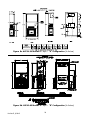
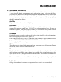
Motorized Damper - 0 to 450 cfm of Outside Air and Pressure Relief (Configuration B)
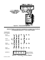
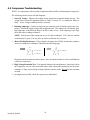
The settings of the damper require a balometer and a thermometer for measuring internal and
external temperatures.
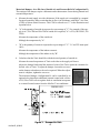
a. Measure the total supply air with a balometer. If the supply air is controlled by a manual
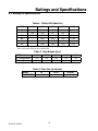
fan speed controller, make certain that the air flow is in accordance with Table 3, Air Flow
(CFM) at Various Static Pressures. This CFM is referred to as "C" in the illustration and
equation below.
b. "A" is the quantity of outside air expressed as a percentage of "C". For example, if the supply air is 1,220 CFM and 300 CFM of outside air is required, "A" is 25% (300 CFM/1,220
CFM)
Measure the temperature of the outside air.
Multiply the temperature by "A".
c. "B" is the quantity of return air expressed as a percentage of "C". "A" and "B" must equal
100%.
Measure the temperature of the indoor return air.
Multiply the temperature of the indoor air by "B".
d. Calculate what the Tmix should be with the desired quantity of outside air.
Measure the actual temperature of Tmix at the inlet to the supply air blower.
Adjust the damper blade until the measured value of the Tmix equals the calculated or
desired value of Tmix. To adjust the damper, loosen the set screw
on the damper rod and move the rod as required. When the adjustment is complete, tighten the set screw.
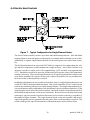
The motorized damper, Configuration B, can be controlled by an
optional relay that allows additional external control with a choice
of 24, 120 or 240V coils to regulate fresh air ventilation in response
to a control located remote from the ModPac™ air conditioner.
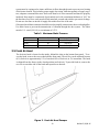
Figure 2. Damper Air Path
ModPac II, 9/09-15
10