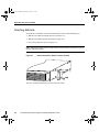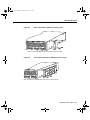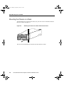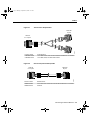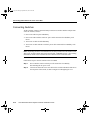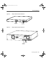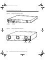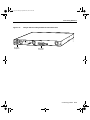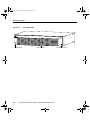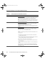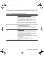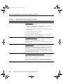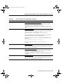
1
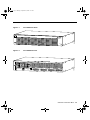
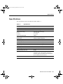
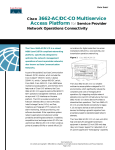
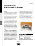
rpsprf Page xi Monday, September 14, 1998 8:20 AM
About This Guide
This section discusses the objectives, audience, organization, and conventions of the
Cisco Redundant Power System Hardware Installation Guide.
Document Objectives
This publication provides installation instructions and troubleshooting information for the
Cisco Redundant Power System (RPS) in the following product lines:
•
Cisco FastHub 100 series, FastHub 200 series, FastHub 300 series 100BaseT hubs, and
HP 10BaseT Hub-16M hubs
•
Catalyst 1900 series switches, Catalyst 2820 series switches, and Catalyst 2900
series XL switches
•
•
Cisco 2500 series routers/access servers, Cisco 2600, 3600, and 4000 series routers
Cisco MC3810 multiservice concentrator
Audience
This publication is designed for people who have some experience installing networking
equipment such as routers, hubs, servers, and switches. The person installing and
troubleshooting the Cisco RPS should be familiar with electronic circuitry and wiring
practices and have experience as an electronic or electromechanical technician.
xi
rpsprf Page xii Monday, September 14, 1998 8:20 AM
Document Organization
Document Organization
Chapter
Title
Description
Preface
About This Guide
Discusses the objectives, audience, organization, and conventions of
this publication and describes how to get additional documentation.
Chapter 1
Overview of the
Cisco RPS
Gives an overview of the Cisco RPS, supported devices,
configurations, features, product specifications, safety
recommendations, and installation prerequisites.
Chapter 2
Installing the Cisco RPS
Provides instructions for setting the Cisco RPS on a desktop or
rack-mounting the Cisco RPS.
Chapter 3
Connecting to External
Devices
Explains how to connect the Cisco RPS to external devices and how
to order cabling appropriate to each device.
Chapter 4
Connecting Cables
Gives steps for connecting the Cisco RPS to the supported external
devices (see Table 1-1).
Appendix A
Replacing an External
Device
Provides steps for replacing a failed external device receiving power
from the Cisco RPS.
Appendix B
Troubleshooting the
Cisco RPS
Provides specifics on troubleshooting the Cisco RPS, isolating
problems to a specific subsystem, and reading front-panel LEDs.
xii
Cisco Redundant Power System Hardware Installation Guide
rpsprf Page xiii Monday, September 14, 1998 8:20 AM
Installation Guide Conventions
Installation Guide Conventions
Convention
Description
Note
Means reader take note. Notes contain helpful suggestions or references to additional
information and material.
Caution
This symbol means reader be careful. In this situation, you might do something that could
result in equipment damage or loss of data.
Warning
This symbol means danger. You are in a situation that could cause bodily injury. Before you
work on any equipment, you must be aware of the hazards involved with electrical circuitry
and be familiar with standard practices for preventing accidents. To see translations of the
various warnings that appear in this publication, refer to the Regulatory Compliance and
Safety Information document that accompanied this device.
Waarschuwing Dit waarschuwingssymbool betekent gevaar. U verkeert in een situatie die
lichamelijk letsel kan veroorzaken. Voordat u aan enige apparatuur gaat werken, dient u zich
bewust te zijn van de bij elektrische schakelingen betrokken risico's en dient u op de hoogte
te zijn van standaard maatregelen om ongelukken te voorkomen. Voor vertalingen van de
waarschuwingen die in deze publicatie verschijnen, kunt u het document Regulatory
Compliance and Safety Information (Informatie over naleving van veiligheids- en andere
voorschriften) raadplegen dat bij dit toestel is ingesloten.
Varoitus Tämä varoitusmerkki merkitsee vaaraa. Olet tilanteessa, joka voi johtaa
ruumiinvammaan. Ennen kuin työskentelet minkään laitteiston parissa, ota selvää
sähkökytkentöihin liittyvistä vaaroista ja tavanomaisista onnettomuuksien ehkäisykeinoista.
Tässä julkaisussa esiintyvien varoitusten käännökset löydät laitteen mukana olevasta
Regulatory Compliance and Safety Information -kirjasesta (määräysten noudattaminen ja
tietoa turvallisuudesta).
Attention Ce symbole d'avertissement indique un danger. Vous vous trouvez dans une
situation pouvant causer des blessures ou des dommages corporels. Avant de travailler sur un
équipement, soyez conscient des dangers posés par les circuits électriques et familiarisezvous avec les procédures couramment utilisées pour éviter les accidents. Pour prendre
connaissance des traductions d’avertissements figurant dans cette publication, consultez le
document Regulatory Compliance and Safety Information (Conformité aux règlements et
consignes de sécurité) qui accompagne cet appareil.
xiii
rpsprf Page xiv Monday, September 14, 1998 8:20 AM
Installation Guide Conventions
Warnung Dieses Warnsymbol bedeutet Gefahr. Sie befinden sich in einer Situation, die zu
einer Körperverletzung führen könnte. Bevor Sie mit der Arbeit an irgendeinem Gerät
beginnen, seien Sie sich der mit elektrischen Stromkreisen verbundenen Gefahren und der
Standardpraktiken zur Vermeidung von Unfällen bewußt. Übersetzungen der in dieser
Veröffentlichung enthaltenen Warnhinweise finden Sie im Dokument Regulatory
Compliance and Safety Information (Informationen zu behördlichen Vorschriften und
Sicherheit), das zusammen mit diesem Gerät geliefert wurde.
Avvertenza Questo simbolo di avvertenza indica un pericolo. La situazione potrebbe
causare infortuni alle persone. Prima di lavorare su qualsiasi apparecchiatura, occorre
conoscere i pericoli relativi ai circuiti elettrici ed essere al corrente delle pratiche standard
per la prevenzione di incidenti. La traduzione delle avvertenze riportate in questa
pubblicazione si trova nel documento Regulatory Compliance and Safety Information
(Conformità alle norme e informazioni sulla sicurezza) che accompagna questo dispositivo.
Advarsel Dette varselsymbolet betyr fare. Du befinner deg i en situasjon som kan føre til
personskade. Før du utfører arbeid på utstyr, må du vare oppmerksom på de faremomentene
som elektriske kretser innebærer, samt gjøre deg kjent med vanlig praksis når det gjelder å
unngå ulykker. Hvis du vil se oversettelser av de advarslene som finnes i denne
publikasjonen, kan du se i dokumentet Regulatory Compliance and Safety Information
(Overholdelse av forskrifter og sikkerhetsinformasjon) som ble levert med denne enheten.
Aviso Este símbolo de aviso indica perigo. Encontra-se numa situação que lhe poderá
causar danos físicos. Antes de começar a trabalhar com qualquer equipamento, familiarize-se
com os perigos relacionados com circuitos eléctricos, e com quaisquer práticas comuns que
possam prevenir possíveis acidentes. Para ver as traduções dos avisos que constam desta
publicação, consulte o documento Regulatory Compliance and Safety Information
(Informação de Segurança e Disposições Reguladoras) que acompanha este dispositivo.
xiv
Cisco Redundant Power System Hardware Installation Guide
rpsprf Page xv Monday, September 14, 1998 8:20 AM
Ordering Additional Documentation
¡Advertencia! Este símbolo de aviso significa peligro. Existe riesgo para su integridad
física. Antes de manipular cualquier equipo, considerar los riesgos que entraña la corriente
eléctrica y familiarizarse con los procedimientos estándar de prevención de accidentes. Para
ver una traducción de las advertencias que aparecen en esta publicación, consultar el
documento titulado Regulatory Compliance and Safety Information (Información sobre
seguridad y conformidad con las disposiciones reglamentarias) que se acompaña con este
dispositivo.
Varning! Denna varningssymbol signalerar fara. Du befinner dig i en situation som kan
leda till personskada. Innan du utför arbete på någon utrustning måste du vara medveten om
farorna med elkretsar och känna till vanligt förfarande för att förebygga skador. Se
förklaringar av de varningar som förkommer i denna publikation i dokumentet Regulatory
Compliance and Safety Information (Efterrättelse av föreskrifter och säkerhetsinformation),
vilket medföljer denna anordning.
Ordering Additional Documentation
Cisco documentation and additional literature are available in a CD-ROM package, which
ships with your Cisco RPS. The Documentation CD-ROM, a member of the Cisco
Connection Family, is updated monthly. Therefore, it might be more up to date than printed
documentation. To order additional copies of the Documentation CD-ROM, contact your
local sales representative or call customer service. The CD-ROM package is available as a
single package or as an annual subscription. You can also access Cisco documentation on
the World Wide Web at http://www.cisco.com, http://www-china.cisco.com, or
http://www-europe.cisco.com. Or you can order printed copies of documentation
separately. See the section, “Cisco Connection Online” later in this preface.
xv
rpsprf Page xvi Monday, September 14, 1998 8:20 AM
Documentation Feedback
Documentation Feedback
You can send us your comments on any Cisco document by using the CCO Feedback
button. Click CCO Feedback. Then click MarketPlace and press Return to access the
feedback form. You can also use the Feedback button to send us your comments on other
CCO content.
If you are reading Cisco product documentation on the World Wide Web, you can submit
comments electronically. Click Feedback in the toolbar and select Documentation. After
you complete the form, click Submit to send it to Cisco. We appreciate your comments.
Cisco Connection Online
Cisco Connection Online (CCO) is Cisco Systems’ primary, real-time support channel.
Maintenance customers and partners can self-register on CCO to obtain additional
information and services.
Available 24 hours a day, 7 days a week, CCO provides a wealth of standard and valueadded services to Cisco’s customers and business partners. CCO services include product
information, product documentation, software updates, release notes, technical tips, the
Bug Navigator, configuration notes, brochures, descriptions of service offerings, and
download access to public and authorized files.
CCO serves a wide variety of users through two interfaces that are updated and enhanced
simultaneously: a character-based version and a multimedia version that resides on the
World Wide Web (WWW). The character-based CCO supports Zmodem, Kermit,
Xmodem, FTP, and Internet e-mail, and it is excellent for quick access to information over
lower bandwidths. The WWW version of CCO provides richly formatted documents with
photographs, figures, graphics, and video, as well as hyperlinks to related information.
You can access CCO in the following ways:
•
•
•
•
xvi
WWW: http://www.cisco.com
WWW: http://www-europe.cisco.com
WWW: http://www-china.cisco.com
Telnet: cco.cisco.com
Cisco Redundant Power System Hardware Installation Guide
rpsprf Page xvii Monday, September 14, 1998 8:20 AM
Cisco Connection Online
•
Modem: From North America, 408 526-8070; from Europe, 33 1 64 46 40 82. Use the
following terminal settings: VT100 emulation; databits: 8; parity: none; stop bits: 1; and
connection rates up to 28.8 kbps.
For a copy of CCO’s Frequently Asked Questions (FAQ), contact [email protected]. For
additional information, contact [email protected].
Note If you are a network administrator and need personal technical assistance with a
Cisco product that is under warranty or covered by a maintenance contract, contact Cisco’s
Technical Assistance Center (TAC) at 800 553-2447, 408 526-7209, [email protected], or
http://www.cisco.com. To obtain general information about Cisco Systems, Cisco products,
or upgrades, contact 800 553-6387, 408 526-7208, or [email protected].
xvii
rpsprf Page xviii Monday, September 14, 1998 8:20 AM
Cisco Connection Online
xviii
Cisco Redundant Power System Hardware Installation Guide
rps1 Page 1 Monday, September 14, 1998 8:17 AM
C H A PT E R
1
Overview of the Cisco RPS
This chapter describes the Cisco 600W RPS, its features, and supported devices. The
Cisco RPS provides power system redundancy to external devices such as routers,
switches, or hubs.
The system includes two fully redundant AC input power modules and four DC output
power modules for connection to external devices. The Cisco RPS supports
quasi-redundant, fully redundant, and redundant-with-reboot configurations.
Table 1-1 lists the supported external devices and power configurations. Figure 1-1 shows
the front panel of the Cisco RPS, and Figure 1-2 shows the rear panel.
Overview of the Cisco RPS 1-1
rps1 Page 2 Monday, September 14, 1998 8:17 AM
Table 1-1
Cisco RPS-Supported External Devices and Power Configurations
External Device
QuasiRedundant
Fully
Redundant
Redundant With
Reboot
FastHub 100 series 100BaseT hubs
Yes
Yes
Yes
FastHub 200 series 100BaseT hubs
Yes
Yes
Yes
FastHub 300 series 100BaseT hubs
Yes
Yes
Yes
HP 10BaseT Hub-16M hub
Yes
No
No
Catalyst 1900 series switches
Yes
Yes
Yes
Catalyst 2820 series switches
Yes
Yes
Yes
Catalyst 2900 series XL switches
Yes
Yes
Yes
Cisco 2500 series routers/access servers
Yes
Yes
No
Cisco 2600 series routers
Yes
Yes
No
Cisco 3600 series routers
Yes
Yes
No
Cisco MC3810 multiservice concentrator
Yes
Yes
No
Cisco 4000 series routers
Yes
Yes
No
Note For simplicity, Cisco 2500 series access servers, such as Cisco 2509 or 2511, are
referred to as Cisco 2500 series routers throughout this guide.
Note You may need to order a power adapter plate for your router or concentrator to make
it compatible for use with the Cisco RPS. See Table 3-2, which lists adapter plates and
corresponding product order numbers. Contact Cisco Customer Service at 800 553-6387 or
408 526-7209 for ordering information. (See also the section “Cisco Connection Online”
in the “About This Guide” preface.)
1-2
Cisco Redundant Power System Hardware Installation Guide
rps1 Page 3 Monday, September 14, 1998 8:17 AM
DC STATUS
1
2
3
4
FAN
Figure 1-2
AC INPUT 1
100-200 V~ 50/60 Hz
10-5 A 1000 W
TEMP
H9588
Cisco RPS Front Panel
Cisco RPS Rear Panel
AC INPUT 2
100-200 V~ 50/60 Hz
10-5 A 1000 W
DC OUTPUT 1
DC OUTPUT 2
DC OUTPUT 3
DC OUTPUT 4
H9589
Figure 1-1
Overview of the Cisco RPS 1-3
rps1 Page 4 Monday, September 14, 1998 8:17 AM
Quasi-Redundant Configuration
Quasi-Redundant Configuration
The Cisco RPS provides a quasi-redundant power source for four external devices that use
up to 150W DC each. You can use a one-to-one cable (one connector at each cable end) to
connect four external devices to the four DC output power modules, as shown in Figure 1-3.
The power source is quasi-redundant because there are two AC input power modules for
the Cisco RPS and one DC output power module for each external device. The AC input to
the Cisco RPS is fully redundant, but the DC output to the external devices is not.
Figure 1-3
Quasi-Redundant Configuration
AC input
AC
NM3998
AC
DC
DC
Cisco RPS
DC
DC
DC output
External devices
150W or less
1-4
Cisco Redundant Power System Hardware Installation Guide
rps1 Page 5 Monday, September 14, 1998 8:17 AM
Fully Redundant Configuration
Fully Redundant Configuration
The Cisco RPS can provide a fully redundant power source for two pieces of equipment.
You can use a two-to-one cable to connect two external devices to the four DC output power
modules, as shown in Figure 1-4. The two-to-one cable is a Y-shaped cable with two
connectors at one end and one connector at the other end.
In this configuration, the connectors at one end of the Y-shaped cable connect two
Cisco RPS DC output power modules to one external device. The power source is fully
redundant because there are two AC input modules and two DC output power modules
connected to each external device. If any power module fails, there is a full backup.
Figure 1-4
Fully Redundant Configuration
AC input
AC
11962
AC
DC
Cisco RPS
DC
DC
DC
DC output
FastHub 100 series, FastHub 200 series, FastHub 300 series,
Catalyst 1900 series and Catalyst 2820 series switches,
Catalyst 2900 series XL switches,
Cisco 2500, 2600, 3600, and 4000 series routers,
Cisco MC3810 multiservice concentrators
Overview of the Cisco RPS 1-5
rps1 Page 6 Monday, September 14, 1998 8:17 AM
Redundant With Reboot
Redundant With Reboot
By using a second mode of redundant operation called redundant with reboot, you can
connect more hubs and switches to the Cisco RPS and thereby extend its capacity. This
configuration also provides switches and hubs (except the HP 10BaseT Hub-16M) with
additional redundancy.
Redundancy with reboot works for the following devices only: FastHub 100 series,
FastHub 200 series, or FastHub 300 series 100BaseT hubs, Catalyst 1900 series,
Catalyst 2820 series switches, and the Catalyst 2900 series XL switches.
Note Cisco recommends that you use configurations without the AC power plug (that is,
not in redundant-with-reboot mode) connected to the external device, due to the reboot and
downtime—approximately 30 seconds.
The redundant-with-reboot configuration is shown in Figure 1-5, where a straight-through
one-to-one cable connects an external device (the figure shows switches, but they could also
be hubs) to the Cisco RPS while the device is simultaneously powered by its own internal
power supply (the device AC power plug is connected).
1-6
Cisco Redundant Power System Hardware Installation Guide
rps1 Page 7 Monday, September 14, 1998 8:17 AM
Redundant With Reboot
Figure 1-5
Redundant-With-Reboot Configuration
AC input
AC
12052
AC
DC
DC
Cisco RPS
DC
DC
DC output
External devices
150W or less
AC power cords
AC power strip
In this configuration, one Cisco RPS can support four devices instead of two. Despite
30 seconds of downtime that occur when using redundancy with reboot, this configuration
provides additional redundancy and extends the capacity of the Cisco RPS.
In this way, the Cisco RPS and external device internal power supply can be connected
simultaneously. A sense circuit in the Cisco RPS reads that the device has its AC power
connected and shuts the Cisco RPS output off. In this way competition between the power
supplies is prevented.
Normally, the external device internal power supply always provides power. If the internal
power system of the external device fails, the device powers down briefly until the
Cisco RPS begins supplying power. When the device comes back up, the Cisco RPS is the
main power source.
Overview of the Cisco RPS 1-7
rps1 Page 8 Monday, September 14, 1998 8:17 AM
Redundant With Reboot
If the Cisco RPS fails or is disconnected, the external device will not power cycle because
its internal power supply has not been disturbed. When both the Cisco RPS and internal
power supply are powered, the LED on the Cisco RPS front panel and the RPS LED on the
external device both blink green.
If you cannot afford the 30-second interruption, unplug the external device AC power cord
and use only the Cisco RPS with the Y-cable. There is no downtime when using the
Cisco RPS with the Y-cable.
1-8
Cisco Redundant Power System Hardware Installation Guide
rps1 Page 9 Monday, September 14, 1998 8:17 AM
Mixed Configuration (Quasi- and Fully Redundant)
Mixed Configuration (Quasi- and Fully Redundant)
You can mix quasi-redundant and fully redundant configurations. For example, two devices
can be in quasi-redundant mode while one is in fully redundant mode (see Figure 1-6).
Figure 1-6
Mixed Configuration
AC input
AC
11681
AC
DC
Cisco RPS
DC
DC
DC
DC output
Fully redundant
Quasi-Redundant
Overview of the Cisco RPS 1-9
rps1 Page 10 Monday, September 14, 1998 8:17 AM
Features
Features
The following features are standard:
•
•
•
•
•
•
•
•
Two AC input power cords
Two fully redundant AC input power modules
Four 150W DC output power modules
Four one-to-one cables (PWR600-AC-RPS-CAB)
Rack-mountable chassis (19-inch rack-mount brackets included)
Redundant cooling fans
LEDs for the AC and DC fans and temperature status
Simple Network Management Protocol (SNMP) support of error messages for
Cisco 2600 and Cisco 3600 series routers.
There is no SNMP support for error messages in the FastHub series 100,
FastHub series 200, FastHub series 300, Catalyst 1900 series, Catalyst 2820 series,
Catalyst 2900 XL switches, Cisco 2500 and 4000 series routers, and the Cisco MC3810
multiservice concentrator.
Note Optional Y-cables (for use with the PWR600-AC-RPS-NCAB—the Cisco RPS
which ships with no cables) can be ordered separately. For ordering information, Contact
Cisco Customer Service at 800 553-6387 or 408 526-7209. See also the section “Cisco
Connection Online,” in the “About This Guide” preface.
1-10
Cisco Redundant Power System Hardware Installation Guide
rps1 Page 11 Monday, September 14, 1998 8:17 AM
Specifications
Specifications
The specifications for the Cisco RPS are listed in Table 1-2.
Table 1-2
Specifications
Description
Specification
Dimensions (H x W x D)
3.44 x 17.5 x 16 in. (8.73 x 44.45 x 40.64 cm)
Weight
27.25 lb (12.36 kg)
Nominal input voltage
Current
Frequency
Absolute maximum input
100 to 240 VAC autoranging
10A maximum
50 to 60 Hz
1000W
Output voltage/maximum current
Output power
+5@24 ADC, +12@5 ADC, –12@3 ADC
150W per module (maximum)
Operating temperature
32 to 104°F (0 to 40°C)
Nonoperating temperature
–4 to 149°F (–20 to 65°C)
Operating humidity
10 to 85%, noncondensing
Nonoperating humidity
5 to 95% noncondensing
Operating altitude
0 to 10,000 ft (0 to 3,000 m)
Nonoperating altitude
0 to 30,000 ft (0 to 9,000 m)
Normal operating noise level
48 dBa
Regulatory compliance
FCC Class B. For additional compliance
information, refer to the Regulatory Compliance
and Safety Information document that accompanied
the Cisco RPS and external devices.
Demonstrated MTBF
In excess of 500,000 hours
Overview of the Cisco RPS 1-11
rps1 Page 12 Monday, September 14, 1998 8:17 AM
Safety Recommendations
Safety Recommendations
Follow these guidelines to guarantee general safety:
•
•
•
Keep the chassis area clear and dust-free during and after installation.
•
•
Wear safety glasses when working under conditions that may be hazardous to your eyes.
Keep tools and chassis components away from walk areas.
Do not wear loose clothing that could get caught in the chassis. Fasten your tie or scarf
and roll up your sleeves.
Do not perform any action that creates a hazard to people or makes the equipment
unsafe.
Safety Warnings
Safety warnings appear throughout this guide in procedures that, if performed incorrectly,
may harm you. A warning symbol precedes each warning statement. (For information on
safety warnings and translations, see “Installation Guide Conventions” in the “About This
Guide” section.)
Safety with Electricity
Follow these guidelines when working on equipment powered by electricity:
•
Locate the emergency power-OFF switch in the room in which you are working. Then,
if an electrical accident occurs, you can quickly shut the power OFF.
Warning Read the installation instructions before you connect the system to its power
source.
Warning The device is designed to work with TN power systems.
Warning Before working on equipment that is connected to power lines, remove jewelry
(including rings, necklaces, and watches). Metal objects will heat up when connected to
power and ground and can cause serious burns or weld the metal object to the terminals.
1-12
Cisco Redundant Power System Hardware Installation Guide
rps1 Page 13 Monday, September 14, 1998 8:17 AM
Safety with Electricity
Warning This product relies on the building’s installation for short-circuit (overcurrent)
protection. Make sure that a fuse or circuit breaker is no larger than 120 VAC, 15A U.S.
(240 VAC, 10A international) is used on the phase conductors (all current-carrying
conductors).
Warning This equipment is intended to be grounded. Make sure that the host is connected
to earth ground during normal use.
•
Look carefully for possible hazards in your work area, such as moist floors, ungrounded
power extension cables, and missing safety grounds.
•
If an electrical accident occurs, proceed as follows:
— Use caution; do not become a victim yourself.
— Turn off power to the Cisco RPS.
— If possible, send another person to get medical aid. Otherwise, determine the
condition of the victim and then call for help.
— Determine if the person needs rescue breathing or external cardiac compressions;
then take appropriate action.
Warning Ultimate disposal of this product should be handled according to all national
laws and regulations.
Overview of the Cisco RPS 1-13
rps1 Page 14 Monday, September 14, 1998 8:17 AM
Safety Recommendations
1-14
Cisco Redundant Power System Hardware Installation Guide
rps2 Page 1 Monday, September 14, 1998 8:17 AM
C H A PT E R
2
Installing the Cisco RPS
You can set the Cisco RPS chassis on a desktop or install it in a rack.
Warning Only trained and qualified personnel should be allowed to install or replace this
equipment.
Warning Do not work on the system or connect or disconnect cables during periods of
lightning activity.
Before opening the chassis, disconnect the telephone-network cables to avoid
contact with telephone-network voltages.
Warning
Warning This equipment is intended to be grounded. Ensure that the host is connected to
earth ground during normal use.
Warning Never defeat the ground conductor or operate the equipment in the absence of a
suitably installed ground conductor. Contact the appropriate electrical inspection authority
or an electrician if you are uncertain that suitable grounding is available.
Warning When installing the unit, the ground connection must always be made first and
disconnected last.
•
•
Do not work alone if potentially hazardous conditions exist.
Never assume that power is disconnected from a circuit. Always check.
Installing the Cisco RPS 2-1
rps2 Page 2 Monday, September 14, 1998 8:17 AM
Setting the Cisco RPS on a Desktop
Use the procedure in this section that best meets your needs:
•
•
Setting the Cisco RPS on a Desktop
Rack-Mounting the Cisco RPS
Setting the Cisco RPS on a Desktop
The location of the Cisco RPS is extremely important for proper operation. Equipment
placed too close together, inadequate ventilation, and inaccessible panels can cause
malfunctions and shutdowns and can make maintenance difficult. The following
information will help you to plan the location of the chassis.
•
•
Plan for access to both the front and rear panels of the Cisco RPS.
Make sure that the room where the Cisco RPS operates has adequate ventilation.
Remember that electrical equipment generates heat. Ambient air temperature may not
cool equipment to acceptable operating temperatures without adequate ventilation.
(See Table 1-2.)
Warning Do not stack the chassis on any other equipment. If the chassis falls, it can cause
severe bodily injury and equipment damage.
Warning This unit is intended for installation in restricted access areas. A restricted access
area is where access can only be gained by service personnel through the use of a special
tool, lock and key, or other means of security, and is controlled by the authority responsible
for the location.
Follow these steps to install your chassis on a desktop:
2-2
Step 1
Unpack the Cisco RPS.
Step 2
Attach the rubber feet included in the accessory kit in the round recesses on the
bottom of the chassis.
Step 3
Set Cisco RPS chassis on an appropriate desktop.
Step 4
Plug in the Cisco RPS and turn power ON.
Cisco Redundant Power System Hardware Installation Guide
rps2 Page 3 Monday, September 14, 1998 8:17 AM
Rack-Mounting the Cisco RPS
Note If you have questions or need assistance, see the section, “Cisco Connection Online”
near the end of the “About This Guide” preface.
Rack-Mounting the Cisco RPS
This sections explains how to rack-mount the Cisco RPS in 19-, 23-, 24-inch, or telco
equipment racks. Read the following information before rack-mounting your chassis.
Planning Your Rack-Mount Installation
Warning To prevent bodily injury when mounting or servicing this unit in a rack, you
must take special precautions to ensure that the system remains stable. The following
guidelines are provided to ensure your safety:
— This unit should be mounted at the bottom of the rack if it is the only
unit in the rack.
— When mounting this unit in a partially filled rack, load the rack from
the bottom to the top with the heaviest component at the bottom of the
rack.
— If the rack is provided with stabilizing devices, install the stabilizers
before mounting or servicing the unit in the rack.
The following information will help you plan your equipment rack installation:
•
Enclosed racks must have adequate ventilation. Make sure that the rack is not congested
because each unit generates heat. Heat generated by equipment near the bottom of the
rack can be drawn upward into the intake ports of the equipment above. An enclosed
rack should have louvered sides and a fan to provide cooling air.
•
When mounting a chassis in an open rack, make sure that the rack frame does not block
the intake or exhaust ports. If the chassis is installed on slides, check the position of the
chassis when it is seated in the rack.
Installing the Cisco RPS 2-3
rps2 Page 4 Monday, September 14, 1998 8:17 AM
Rack-Mounting the Cisco RPS
•
Baffles can isolate exhaust air from intake air, which also helps to draw cooling air
through the chassis. The best placement of the baffles depends on the airflow patterns in
the rack, which can be found by experimenting with different configurations.
•
When equipment installed in a rack (particularly in an enclosed rack) fails, try operating
the equipment by itself, if possible. Power off other equipment in the rack and in
adjacent racks to allow the unit under test a maximum of cooling air and clean power.
•
Install the Cisco RPS and the external device to which it will connect in adjacent shelves
in a rack.
Tools and Equipment Required
You need the following tools and equipment to rack-mount the Cisco RPS:
•
•
•
Number 2 Phillips screwdriver (not included)
Screws for attaching the Cisco RPS to the rack (not included)
Rack-mount brackets (see Figure 2-1 and Figure 2-2):
— One set of 19-inch brackets (ACS-3640RM-19=) ships with the Cisco RPS.
— Order 23- or 24-inch brackets (ACS-3640RM-24=) as needed.
— Order telco brackets (AS52/3RM-TELCO-19=) as needed.
2-4
Cisco Redundant Power System Hardware Installation Guide
rps2 Page 5 Monday, September 14, 1998 8:17 AM
Identifying Rack-Mount Brackets
Identifying Rack-Mount Brackets
Figure 2-1 and Figure 2-2 show 19-, 23-, 24-inch, and telco brackets.
Figure 2-1
19-, 23-, and 24-inch Rack-Mount Brackets
Use with 23-inch rack
H9695
Use with 24-inch rack
Bracket for 19-inch rack
Telco Bracket
10253
Figure 2-2
Bracket for 23- and 24-inch rack
Installing the Cisco RPS 2-5
rps2 Page 6 Monday, September 14, 1998 8:17 AM
Rack-Mounting the Cisco RPS
Attaching Brackets
To install the Cisco RPS in a rack, attach the brackets in one of the following ways:
•
•
•
With the Cisco RPS front panel forward (see Figure 2-3).
With the Cisco RPS rear panel forward (see Figure 2-4).
In a center-mount telco rack (see Figure 2-5).
Note Although the figures show 19-inch brackets, the procedure is the same for 23-inch,
24-inch, and telco brackets.
Bracket Installation—RPS Front Panel Forward
H9696
Figure 2-3
DC STATUS
1
2
3
4
FAN
TEMP
Note: The second bracket attaches to the other side of the chassis.
2-6
Cisco Redundant Power System Hardware Installation Guide
rps2 Page 7 Monday, September 14, 1998 8:17 AM
Attaching Brackets
Bracket Installation—RPS Rear Panel Forward
H9697
Figure 2-4
DC OUTPUT 2
DC OUTPUT 3
DC OUTPUT 4
Note: The second bracket attaches to the other side of the chassis.
Telco Bracket Installation—RPS Rear Panel Forward
11540
Figure 2-5
DC OUTPUT 3
DC OUTPUT 4
Note: The second bracket attaches to the other side of the chassis.
Installing the Cisco RPS 2-7
rps2 Page 8 Monday, September 14, 1998 8:17 AM
Rack-Mounting the Cisco RPS
Mounting the Chassis in a Rack
After the brackets are secured to the chassis, use your own screws to attach the chassis to
the rack, as shown in Figure 2-6.
Attaching the Chassis to a Rack—Rear Panel Forward
H9699
Figure 2-6
DC OUTPUT 3
DC OUTPUT 4
Note: The second bracket attaches to the rack at the other side of the chassis.
2-8
Cisco Redundant Power System Hardware Installation Guide
rps3 Page 1 Monday, September 14, 1998 8:17 AM
C H A PT E R
3
Connecting to External Devices
This section describes how to connect the Cisco RPS to external devices. The Cisco RPS
includes two fully redundant AC input power modules and four DC output power modules
for connection to external devices. The Cisco RPS supports quasi-redundant, fully
redundant, and redundant-with-reboot configurations. For an explanation of power source
configurations, refer to Chapter 1, “Overview of the Cisco RPS.”
Caution The Cisco RPS AC input power modules are power-factor-corrected to comply
with certain International Electrotechnical Commission (IEC) standards. Do not connect
the Cisco RPS to an uninterruptible power supply (UPS) that has not been tested and
designed for power-factor-corrected power systems. Do not connect the Cisco RPS to a
ferro-resonant transformer. If you do either of these things, you could damage the
Cisco RPS.
Tools and Equipment Required
You may need the following tools and equipment:
•
•
Y-cable—Needed for fully redundant power configurations.
Upgrade kit—Needed for routers that originally came with AC or DC power supplies
(Cisco 2500, 2600, 3600, 4000 series routers or the Cisco MC3810 multiservice
concentrator).
Connecting to External Devices 3-1
rps3 Page 2 Monday, September 14, 1998 8:17 AM
Cables
Cables
The Cisco RPS ships in either of the following configurations:
•
With four cables of one-to-one configuration (22-pin to 18-pin) for quasi-redundant
powering of up to four external devices (Cisco RPS number PWR600-AC-RPS-CAB).
•
Without cables (Cisco RPS number PWR600-AC-RPS-NCAB) for fully redundant
powering of up to two external devices. If you want a fully redundant power source, you
will need to order Y-shaped two-to-one cables separately.
Figure 3-1 and Figure 3-2 show the cables you can order, and Table 3-1 lists the
corresponding product order numbers. For ordering information, Contact Cisco Customer
Service at 800 553-6387 or 408 526-7209. See also the section “Cisco Connection Online,”
in the “About This Guide” preface.
3-2
Cisco Redundant Power System Hardware Installation Guide
rps3 Page 3 Monday, September 14, 1998 8:17 AM
Cables
Figure 3-1
Two-to-One Y-Shaped Cable
RPS side
22 pins
11538
Load unit
8 or 18 pins
Product number
CAB-RPSY-2208
CAB-RPSY-2218
One-to-One (Point-to-Point) Cable
Load unit
8 or 18 pins
Product number
CAB-RPS-2208
CAB-RPS-2218
RPS side
22 pins
11539
Figure 3-2
External device
Cisco 2500 series router and Cisco MC3810 multiservice concentrator
Cisco 2600, 3600, and 4000 series routers
External device
Cisco 2500 series router and Cisco MC3810 multiservice concentrator
All others
Connecting to External Devices 3-3
rps3 Page 4 Monday, September 14, 1998 8:17 AM
Cables
Table 3-1
Redundancy
Configuration
Quasi-Redundant
Fully Redundant
Redundant with
Reboot
Cable Order Numbers
Cable Order
Number
For Use With
Cable Description
HP 10BaseT Hub-16M, FastHub 100
series, FastHub 200 series, and
FastHub 300 series 100BaseT hubs,
Catalyst 1900 and Catalyst 2820 series
switches, Catalyst 2900 series XL
switches, Cisco 2600, 3600, and 4000
series routers
One-to-one cable, 22-pin to
18-pin, 4 ft (1.22 m)1
CAB-RPS-2218=2
Cisco 2500 series routers and
Cisco MC3810 multiservice
concentrators
One-to-one cable, 22-pin to
8-pin, 4 ft (1.22 m)1
CAB-RPS-2208=
FastHub 100 series, FastHub 200 series,
and FastHub 300 series 100BaseT hubs,
Catalyst 1900 and Catalyst 2820 series
switches, Catalyst 2900 series XL
switches, Cisco 2600, 3600, and 4000
series routers
Two-to-one cable, 22-pin to
18-pin, 4 ft (1.22 m)1
CAB-RPSY-2218=
Cisco 2500 series routers and
Cisco MC3810 multiservice
concentrators
Two-to-one cable, 22-pin to
8-pin, 4 ft (1.22 m)1
CAB-RPSY-2208=
FastHub 100 series, FastHub 200 series,
and FastHub 300 series 100BaseT hubs,
Catalyst 1900 and Catalyst 2820 series
switches, Catalyst 2900 series XL
switches
One-to-one cable, 22-pin to
18-pin, 4 ft (1.22 m)1
CAB-RPS-2218=2
1. The cables come in one length only. Custom cable-lengths are not available. Excessive voltage drop and marginal or failed operation
can occur with cables of different lengths. Use of cables other than the ones provided can cause damage to the Cisco RPS or router.
2. If you have a Catalyst 1900 series switch (WS-C1900, WS-C1912, or WS-C1900C), depending on when it was manufactured, you
might need a special cable. CAB-RPS-2218A(=) used for pre-EN or-A models of the Catalyst 1900 series and Catalyst 2820 series
switches. Contact Cisco’s Technical Assistance Center (TAC) at 800 533-2447, 408 526-7209, [email protected], or
http://www.cisco.com. Be ready to provide the serial number of your Catalyst 1900 series switch and the part number of the special
cable (72-1327-01).
3-4
Cisco Redundant Power System Hardware Installation Guide
rps3 Page 5 Monday, September 14, 1998 8:17 AM
Upgrade Kit With Power Adapter Plate for Routers and Concentrators
Upgrade Kit With Power Adapter Plate for Routers and
Concentrators
To operate an external device with the Cisco RPS, the device must have an RPS connector.
Cisco 2500, 2600, 3600 and 4000 series routers and the Cisco MC3810 multiservice
concentrator do not automatically ship with an RPS connector.
Note The FastHub 100 series, FastHub 200 series, and FastHub 300 series 100BaseT
hubs, HP 10BaseT Hub-16M, Catalyst 1900 and Catalyst 2820 series switches, and
Catalyst 2900 series XL switches come with an RPS connector and do not require a power
adapter plate.
If you did not specify that you wanted the RPS connector installed on your router or
concentrator when you ordered it, you must order a power adapter plate that provides this
compatibility with the Cisco RPS and install the plate in place of your existing power
supply.
If you need to order a power adapter plate for your router or concentrator, see Table 3-2,
which lists adapter plates and corresponding product order numbers. Contact
Cisco Customer Service at 800 553-6387 or 408 526-7209 for ordering information. (See
also the section “Cisco Connection Online” in the “About This Guide” preface.)
Table 3-2
Power Adapter Plate Product Numbers
Description
Product Number
Cisco 2500 series, Cisco MC3810 adapter plate
ACS-2500RPS=
Cisco 2600 series adapter plate
ACS-2600RPS=
Cisco 3620 adapter plate
ACS-3620RPS=
Cisco 3640 adapter plate
ACS-3640RPS=
Cisco 4000 series adapter plate
ACS-4000RPS=
Connecting to External Devices 3-5
rps3 Page 6 Monday, September 14, 1998 8:17 AM
Upgrade Kit With Power Adapter Plate for Routers and Concentrators
Device-specific instructions for this procedure are shipped with the RPS power adapter
plate when you order it, or are available in Cisco Connection Online (CCO)
at: http://www.cisco.com.
3-6
Cisco Redundant Power System Hardware Installation Guide
rps4 Page 1 Monday, September 14, 1998 8:19 AM
C H A PT E R
4
Connecting Cables
This chapter provides instructions on cabling your external device to the Cisco RPS and is
divided into three major sections:
•
•
•
Connecting Hubs
Connecting Switches
Connecting Routers and the Cisco MC3810
Connecting Cables 4-1
rps4 Page 2 Monday, September 14, 1998 8:19 AM
Cabling Options
Cabling Options
The external devices have different configuration and cabling options outlined below and
discussed in detail in the “Connecting External Devices to the Cisco RPS” section of this
chapter:
•
FastHub 100, FastHub 200, and FastHub 300 series 100BaseT hubs support:
— One-to-one cable for quasi-redundancy
— Option to connect the AC power cable for redundancy with reboot
— Two-to-one Y-cable for full redundancy
— Two-to-one Y-cable with the switch AC power cable connected for redundancy with
reboot
Note The HP 10BaseT Hub-16M supports only a one-to-one cable for quasi-redundant
configuration. This hub does not support connection of its AC power cable for redundancy
with reboot, nor does it support use of the Y-cable for full redundancy.
•
Catalyst 1900 series, Catalyst 2820 series switches and Catalyst 2900 series XL
switches support:
— One-to-one cable for quasi-redundancy
— One-to-one cable with the switch AC power cable connected for redundancy with
reboot
— Two-to-one Y-cable for full redundancy
— Two-to-one Y-cable with the switch AC power cable connected for redundancy with
reboot
•
Cisco 2500, 2600, 3600 and 4000 series routers and the Cisco MC3810 multiservice
concentrator support:
— One-to-one cable for quasi-redundancy
— Two-to-one Y-cable for full redundancy
4-2
Cisco Redundant Power System Hardware Installation Guide
rps4 Page 3 Monday, September 14, 1998 8:19 AM
Connecting External Devices to the Cisco RPS
Connecting External Devices to the Cisco RPS
Note If you want to connect an additional external device to a Cisco RPS that is already
powered up, you can do so without interrupting power to the Cisco RPS or any other
external devices that are already connected. Be sure to connect your cable to the Cisco RPS
first and then to the external device.
Warning Use the Cisco RPS (model PWR600-AC-RPS) only to power the external
device.
Warning Attach only the Cisco RPS (model PWR600-AC-RPS) to the RPS receptacle.
Warning Before performing any of the following procedures, ensure that power is
removed from the DC circuit. To ensure that all power is OFF, locate the circuit breaker on
the panel board that services the DC circuit, switch the circuit breaker to the OFF position,
and tape the switch handle of the circuit breaker in the OFF position.
Warning Before working on a system that has an On/off switch, turn OFF the power and
unplug the power cord.
Warning This unit might have more than one power cord. To reduce the risk of electric
shock, disconnect the two power supply cords before servicing the unit.This unit might
have more than one power cord. To reduce the risk of electric shock, disconnect the two
power supply cords before servicing the unit.
Connecting Cables 4-3
rps4 Page 4 Monday, September 14, 1998 8:19 AM
Connecting External Devices to the Cisco RPS
Connecting Hubs
This section provides illustrations and cabling information for connecting the Cisco RPS to
the following hubs:
•
•
•
•
HP 10BaseT Hub-16M (Figure 4-1)
FastHub 100 series 100BaseT hubs (Figure 4-2)
FastHub 200 series 100BaseT hubs (Figure 4-2)
FastHub 300 series 100BaseT hubs (Figure 4-3)
All hubs can use the one-to-one cable configuration for quasi-redundancy. The
FastHub 100 series, FastHub 200 series, and FastHub 300 series also support the option of
connecting the AC power cord for redundancy with reboot, and use of the Y-cable for fully
redundant configuration.
The HP 10BaseT Hub-16M does not support redundancy with reboot nor does it support
use of the Y-cable for full redundancy.
Follow these steps to connect hubs to the Cisco RPS:
4-4
Step 1
Power OFF the hub to which you will connect the Cisco RPS by disconnecting
the power cord.
Step 2
Connect one end of the one-to-one cable or the two-to-one-Y-cable to the RPS
connector on the hub rear panel. (For connector locations, see Figure 4-1,
Figure 4-2, and Figure 4-3.)
Cisco Redundant Power System Hardware Installation Guide
rps4 Page 5 Monday, September 14, 1998 8:19 AM
Connecting Hubs
HP 10BaseT Hub-16M Rear Panel
11537
Figure 4-1
RS-232
Power receptacle
Serial port
Redundant
power system
connector
FastHub 100 Series and FastHub 200 Series Rear Panel
H9911
Figure 4-2
Reset
switch
RATING
100-127/200-240V~
0.5A/0.3A 50-60Hz
AC power
receptacle
CONSOLE PORT
For FastHub 200
and Catalyst only
DC INPUTS FOR REMOTE
POWER SUPPLY SPECIFIED
IN MANUAL.
+5V 6A +12V 1A
AUI
For Catalyst only
Cisco RPS
connector
Connecting Cables 4-5
rps4 Page 6 Monday, September 14, 1998 8:19 AM
Connecting External Devices to the Cisco RPS
Figure 4-3
FastHub 300 Series Rear Panel
MODEL NO.# 32905 1996, U.S.A.
DC INPUTS FOR REMOTE
POWER SUPPLY SPECIFIED
IN MANUAL. +5V @ 8A,
+12V @ 1A, -12V @ 0.5A
DOWN
UP
DC INPUTS
AC power
receptacle
4-6
Cisco RPS
connector
Cisco Redundant Power System Hardware Installation Guide
H9423
SERIAL NUMBER: 23985001119584856
INPUT POWER RATING: 115/230
V; 60/50 HZ; 5/3.5 A
SEE INSTALLATION INSTRUCTIONS
FOR PROPER SELECTION OF POWER
SUPPLY CORD.
CONFORMS TO US STANDARDS
FOR MAGNETIC EMISSION
rps4 Page 7 Monday, September 14, 1998 8:19 AM
Connecting Hubs
Step 3
Figure 4-5
AC INPUT 1
100-200 V~ 50/60 Hz
10-5 A 1000 W
AC INPUT 2
100-200 V~ 50/60 Hz
10-5 A 1000 W
DC OUTPUT 1
DC OUTPUT 2
DC OUTPUT 3
DC OUTPUT 4
H9790
AC INPUT 1
100-200 V~ 50/60 Hz
10-5 A 1000 W
Connecting a One-to-One Cable for Quasi-Redundant Power
Connecting a Two-to-One Y-Cable for Fully Redundant Power
AC INPUT 2
100-200 V~ 50/60 Hz
10-5 A 1000 W
DC OUTPUT 1
DC OUTPUT 2
DC OUTPUT 3
DC OUTPUT 4
H9791
Figure 4-4
Connect the other end of the one-to-one cable or the two-to-one cable to a
rear-panel connector on the Cisco RPS, as shown in Figure 4-4 and Figure 4-5.
Connecting Cables 4-7
rps4 Page 8 Monday, September 14, 1998 8:19 AM
Connecting External Devices to the Cisco RPS
Step 4
Connecting the AC Power Cables to the Cisco RPS
H9694
Figure 4-6
On the rear panel of the Cisco RPS, connect an AC power cable to either or both
of the power connectors. Use cable locks—included with the Cisco RPS—to
lock the cables in place. (See Figure 4-6.)
Cable locks
4-8
Step 5
Plug the other end of the Cisco RPS AC power cable into a grounded AC power
outlet at your site.
Step 6
If you are using the redundant-with-reboot configuration, plug the hub AC
power cord into a grounded AC power outlet.
Cisco Redundant Power System Hardware Installation Guide
rps4 Page 9 Monday, September 14, 1998 8:19 AM
Connecting Hubs
Step 7
Powering ON the Cisco RPS
H9700
Figure 4-7
Power ON the Cisco RPS. There is one power switch for each AC input power
module. Make sure the power switch is ON (|) for each AC power module used.
(See Figure 4-7.)
The Cisco RPS provides power in 10 to 15 seconds. The Cisco RPS is working
properly when all its front-panel LEDs are solid green. If the external device
does not power up, refer to Appendix B, “Troubleshooting the Cisco RPS.”
Step 8
If you are using the redundant-with-reboot configuration, press the power switch
on the hub to the ON (|) position to begin providing power simultaneously with
the Cisco RPS.
Connecting Cables 4-9
rps4 Page 10 Monday, September 14, 1998 8:19 AM
Connecting External Devices to the Cisco RPS
Connecting Switches
All the switches (Catalyst 1900 and Catalyst 2820 series switches and the Catalyst 2900
series XL switches) can use:
•
•
One-to-one cable for quasi-redundancy
•
•
Two-to-one Y-cable for full redundancy
One-to-one cable with the switch AC power cable connected for redundancy with
reboot
Two-to-one Y-cable with the switch AC power cable connected for redundancy with
reboot
Note Depending on when it was manufactured, a Catalyst 1900 series switch (WS-C1900,
WS-C1912, or WS-C1900C) may need a special cable: CAB-RPS-2218A(=). For ordering
information, contact Cisco Customer Service at 800 553-6387 or 408 526-7209.
Follow these steps to connect switches to the Cisco RPS:
4-10
Step 1
Power OFF the switch to which you will connect the Cisco RPS by
disconnecting the AC power cord.
Step 2
Connect one end of the one-to-one cable or the Y-cable to the RPS connector on
the rear panel of the switch, as shown in Figure 4-8 through Figure 4-12.
Cisco Redundant Power System Hardware Installation Guide
rps4 Page 11 Monday, September 14, 1998 8:19 AM
Connecting Switches
Catalyst 1900 Series Switch Rear Panel
11774
Figure 4-8
RATING
100-127/200-240V~
0.6A/0.3A 50-60Hz
CONSOLE PORT
For FastHub200
and Catlayst only
AC power
receptacle
SPECIFIED IN MANUAL.
+5V @6A, +12V @1A
AUI
For Catalyst only
Cisco RPS
connector
Catalyst 2820 Series Switch Rear Panel
H9426
Figure 4-9
DC INPUTS FOR REMOTE
POWER SUPPLY
CONSOLE PORT
DC INPUTS FOR USE WITH
POWER SUPPLY SPECIFIED
IN MANUAL. +5V @ 8A,
+12V @ 1A, -12V @ 1A
RESET
AUI
Cisco RPS
connector
AC power
receptacle
Connecting Cables 4-11
rps4 Page 12 Monday, September 14, 1998 8:19 AM
Connecting External Devices to the Cisco RPS
Catalyst 2908 XL Switch Rear Panel
12202
Figure 4-10
DC INPUT
CONSOLE
RATING
100-120/200-240V ~
0.7A/0.4A 50-60HZ
DC INPUTS FOR REMOTE
POWER SUPPLY
SPECIFIED IN MANUAL.
+5V
@8A, +12V @0.5A
Figure 4-11
Cisco RPS
connector
Catalyst 2916M XL Switch Rear Panel
RATING
100-120/200-240V ~
2.0A/1.0A 50-60HZ
DC INPUTS FOR REMOTE
POWER SUPPLY
SPECIFIED IN MANUAL.
+5V @24A, +12V @1.0A
DC INPUT
CONSOLE
Cisco RPS
connector
4-12
Cisco Redundant Power System Hardware Installation Guide
AC power
receptacle
12278
AC power
receptacle
rps4 Page 13 Monday, September 14, 1998 8:19 AM
Connecting Switches
Catalyst 2924 and Catalyst 2924C XL Switch Rear Panel
H11751
Figure 4-12
RATING
100-127/200-240V~
1.0A/O.5A 50-80HZ
DC INPUTS FOR REMOTE
POWER SUPPLY
SPECIFIED IN MANUAL
+5V
@9A, +12V
@0.5A
AC power
receptacle
Cisco RPS
connector
Connecting Cables 4-13
rps4 Page 14 Monday, September 14, 1998 8:19 AM
Connecting External Devices to the Cisco RPS
Step 3
Figure 4-14
AC INPUT 1
100-200 V~ 50/60 Hz
10-5 A 1000 W
4-14
AC INPUT 2
100-200 V~ 50/60 Hz
10-5 A 1000 W
DC OUTPUT 1
DC OUTPUT 2
DC OUTPUT 3
DC OUTPUT 4
H9790
AC INPUT 1
100-200 V~ 50/60 Hz
10-5 A 1000 W
Connecting a One-to-One Cable for Quasi-Redundant Power
Connecting a Two-to-One Y-Cable for Fully Redundant Power
AC INPUT 2
100-200 V~ 50/60 Hz
10-5 A 1000 W
DC OUTPUT 1
DC OUTPUT 2
DC OUTPUT 3
Cisco Redundant Power System Hardware Installation Guide
DC OUTPUT 4
H9791
Figure 4-13
Connect the other end of the one-to-one cable or Y-cable to the rear-panel
connector on the Cisco RPS, as shown in Figure 4-13 and Figure 4-14.
rps4 Page 15 Monday, September 14, 1998 8:19 AM
Connecting Switches
Step 4
On the rear panel of the Cisco RPS, connect an AC power cable to either or both
of the power connectors. Use cable locks—included with the Cisco RPS—to
lock the cables in place. (See Figure 4-15.)
Connecting the AC Power Cables to the Cisco RPS
H9694
Figure 4-15
Cable locks
Step 5
Plug the other end of the Cisco RPS AC power cable into a grounded AC power
outlet at your site.
Step 6
If you are using the redundant-with-reboot configuration, plug the switch AC
power cord into a grounded AC power outlet now.
Connecting Cables 4-15
rps4 Page 16 Monday, September 14, 1998 8:19 AM
Connecting External Devices to the Cisco RPS
Step 7
Power ON the Cisco RPS. There is one power switch for each of the AC input
power modules. Make sure the power switch for each connected AC cable is
ON (|). (See Figure 4-16.)
Powering ON the Cisco RPS
H9700
Figure 4-16
The Cisco RPS provides power in 10 to 15 seconds. The Cisco RPS is working
properly when all its front panel LEDs are solid green. If the external device
does not power up, refer to Appendix B, “Troubleshooting the Cisco RPS.”
Step 8
4-16
If you are using the redundant-with-reboot configuration, press the switch power
switch to ON (|) to begin providing power simultaneously with the Cisco RPS.
Cisco Redundant Power System Hardware Installation Guide
rps4 Page 17 Monday, September 14, 1998 8:19 AM
Connecting Routers and the Cisco MC3810
Connecting Routers and the Cisco MC3810
This section provides illustrations and cabling information for connecting the Cisco RPS to
Cisco 2500, 2600, 3600 and 4000 series routers and the Cisco MC3810 multiservice
concentrator. All these devices use:
•
•
One-to-one cable for quasi-redundancy
Two-to-one Y-cable for full redundancy
Note If your router does not have a Cisco RPS connector on its rear panel, you will need
to convert your router by removing its existing power supply and replacing it with a Cisco
power adapter plate.
See Chapter 3, “Connecting to External Devices,” for more information about power
adapter plates and for product order numbers. Device-specific instructions for this
procedure are shipped with the RPS power adapter plate when you order it, or are available
in Cisco Connection Online (CCO) at: http://www.cisco.com.
Note Cisco IOS Release 11.2(7)P or later is required when using Cisco 3600 series routers
with the Cisco RPS.
Follow these steps to connect a router or multiservice concentrator to the Cisco RPS:
Step 1
Power OFF the router or concentrator to which you will connect the Cisco RPS
by pressing the power switch to the OFF (O) position.
Step 2
Connect one end of the one-to-one cable or Y-cable to the RPS connector on the
rear panel of the router or concentrator, as shown in Figure 4-17 through
Figure 4-22.
Connecting Cables 4-17
rps4 Page 18 Monday, September 14, 1998 8:19 AM
Connecting External Devices to the Cisco RPS
Cisco 2500 Series Router Rear Panel
Input: 100-240VAC
Freq: 50/60 Hz
Current: 1.2-0.6A
Watts: 40W
TOKEN RING
H9425
Figure 4-17
Cisco RPS
connector
On/off
switch
Cisco 2600 Series Router Rear Panel
11751
Figure 4-18
SERIAL 1
SERIAL 1
SERIAL 0
CONN
SEE MANUAL BEFORE INSTALLATION
WIC
CONN 2A/S
SERIAL 0
CONN
Cisco 2611
WIC
CONN 2A/S
SEE MANUAL BEFORE INSTALLATION
W0
LINK
LINK ETHERNET 0 ACT CONSOLE
AUX
Cisco RPS
connector
On/off switch
4-18
Cisco Redundant Power System Hardware Installation Guide
rps4 Page 19 Monday, September 14, 1998 8:19 AM
Connecting Routers and the Cisco MC3810
DO NOT INSTALL WAN INTERFACE
CARDS WITH POWER APPLIED
2W
ACT
ETHERNET 0
LNK
ETHERNET 1
AUI
EN
ACT
ACT
SERIAL
LNK
LNK
ACT
1
WO 2E W1
SERIAL
INSTALLATION
12276
BRI
NT1
B2
SEE MANUAL BEFORE
LNK
B1
ACT
NT1
2E
W1
2W
Cisco 3620 Router Rear Panel
ACT
Figure 4-19
ETHERNET
ETH 1 1
AUI
EN
0
ETHERNET 0
DC INPUT FOR USE WITH
CISCO RPS
+5V– – –14A, +12V– – –5A,
-12V– – –3A
Cisco RPS connector
Figure 4-20
Cisco 3640 Router Rear Panel
Cisco RPS
connector
On/off switch
2
WO 2E W1
DO NOT INSTALL WAN INTERFACE
CARDS WITH POWER APPLIED
2W
SERIAL
ETHERNET 1
ETHERNET 0
ETHERNET 1
ACT
LNK
STP
LNK
AUI
EN
ACT
LNK
SERIAL
ACT
LNK
ACT
SEE MANUAL BEFORE INSTALLATION
1
12277
BRI
NT1
B2
ACT
B1
ACT
2E
W1
2W
NT1
3
AUI
EN
ETHERNET 0
INPUT 100-240VAC 50/60HZ 3.0-1.5 AMPS
Power supply
Connecting Cables 4-19
rps4 Page 20 Monday, September 14, 1998 8:19 AM
Connecting External Devices to the Cisco RPS
Cisco 4000 Series Router Rear Panel
11750
Figure 4-21
On/off
switch
Cisco MC3810 Multiservice Concentrator Rear Panel
12212
Figure 4-22
Cisco RPS
connector
AVM
1
2
3
4
5
P
O
W
E
R
6
ETHERNET 0
SERIAL 0
SERIAL 1
CONSOLE
AUX
Cisco RPS
connector
On/off switch
4-20
Cisco Redundant Power System Hardware Installation Guide
rps4 Page 21 Monday, September 14, 1998 8:19 AM
Connecting Routers and the Cisco MC3810
Step 3
Figure 4-24
AC INPUT 1
100-200 V~ 50/60 Hz
10-5 A 1000 W
AC INPUT 2
100-200 V~ 50/60 Hz
10-5 A 1000 W
DC OUTPUT 1
DC OUTPUT 2
DC OUTPUT 3
DC OUTPUT 4
H9790
AC INPUT 1
100-200 V~ 50/60 Hz
10-5 A 1000 W
Connecting a One-to-One Cable for Quasi-Redundant Power
Connecting a Two-to-One Y-Cable for Fully Redundant Power
AC INPUT 2
100-200 V~ 50/60 Hz
10-5 A 1000 W
DC OUTPUT 1
DC OUTPUT 2
DC OUTPUT 3
DC OUTPUT 4
H9791
Figure 4-23
Connect the other end of the one-to-one or Y-cable to the rear panel connector
on the Cisco RPS, as shown in Figure 4-23 and Figure 4-24.
Connecting Cables 4-21
rps4 Page 22 Monday, September 14, 1998 8:19 AM
Connecting External Devices to the Cisco RPS
Step 4
On the rear panel of the Cisco RPS, connect an AC power cable to either or both
of the power connectors. Use cable locks—included with the Cisco RPS—to
lock the cables in place. (See Figure 4-25.)
Connecting the AC Power Cables to the Cisco RPS
H9694
Figure 4-25
Cable locks
Step 5
4-22
Plug the other end of the Cisco RPS AC power cable into a grounded AC power
outlet at your site.
Cisco Redundant Power System Hardware Installation Guide
rps4 Page 23 Monday, September 14, 1998 8:19 AM
Connecting Routers and the Cisco MC3810
Step 6
Power ON the Cisco RPS. There is one power switch for each of the AC input
power modules. Make sure the power switch for each connected AC cable is
ON (|). (See Figure 4-26.)
Powering ON the Cisco RPS
H9700
Figure 4-26
The Cisco RPS is on and provides power in 10 to 15 seconds. The Cisco RPS is
working properly when all its front-panel LEDs are solid green. If the external
device does not power up, refer to Appendix B, “Troubleshooting the
Cisco RPS.”
Connecting Cables 4-23
rps4 Page 24 Monday, September 14, 1998 8:19 AM
Connecting External Devices to the Cisco RPS
4-24
Cisco Redundant Power System Hardware Installation Guide
rpsappa Page 1 Monday, September 14, 1998 8:18 AM
A P PEN D I X
A
Replacing an External Device
If an external device (hub, switch, router or concentrator) that is receiving power from the
Cisco RPS fails, you can replace it without powering down the Cisco RPS or interrupting
power to any other external devices. Take these steps to replace a failed external device that
is connected to the Cisco RPS:
Note Do not power down the Cisco RPS.
Step 1
Power OFF the external device.
(a)
If the external device is a router or concentrator, press the On/off switch to
the OFF position.
(b)
If the external device is a hub or switch, disconnect the AC power cord.
Step 2
Disconnect the external device from the Cisco RPS. Make sure to leave the
power cable connected to the Cisco RPS.
Step 3
Replace the failed external device.
Step 4
Reconnect the new external device to the Cisco RPS power cable.
Step 5
Power ON the external device.
(a)
If the external device is a router or concentrator, press the On/off switch to
the ON (|) position.
(b)
If the external device is a hub or switch, connect the device AC power cord.
The new external device powers up in 10 to 15 seconds.
Replacing an External Device A-1
rpsappa Page 2 Monday, September 14, 1998 8:18 AM
If you have questions or need assistance, see the section, “Cisco Connection Online” near
the end of the “About This Guide” preface.
A-2
Cisco Redundant Power System Hardware Installation Guide
rpsappb Page 1 Monday, September 14, 1998 8:19 AM
A P PEN D I X
B
Troubleshooting the Cisco RPS
The key to troubleshooting is to isolate the problem to a specific subsystem. Start by
reading the LEDs on the front panel of the Cisco RPS and any error messages displayed on
the external device console. If you are unable to resolve the problem, refer to the section
“Cisco Connection Online” in the “About This Guide” preface.
Reading the LEDs
The LEDs on the front panel of the Cisco RPS display the current operating condition of
the Cisco RPS:
•
•
•
Two AC STATUS LEDs—Left side of the front panel.
Four DC STATUS LEDs—Center of the front panel.
Two LEDs, FAN and TEMP—Right side of the front panel.
When the Cisco RPS is working properly, all LEDs on its front panel are solid green.
Note Some external devices also include LEDs that show the operating condition of the
Cisco RPS. Refer to the installation guide that accompanied the device for detailed
information about the LEDs.
Figure B-1 shows the LEDs on the front panel of the Cisco RPS, and Table B-1 explains
the meaning of the colors.
Troubleshooting the Cisco RPS B-1
rpsappb Page 2 Monday, September 14, 1998 8:19 AM
Reading the LEDs
Figure B-1
Cisco RPS LEDs
1
2
3
4
FAN
AC status LEDs
B-2
DC status LEDs
Cisco Redundant Power System Hardware Installation Guide
TEMP
Fan and temp LEDs
H9629
DC STATUS
rpsappb Page 3 Monday, September 14, 1998 8:19 AM
Reading the LEDs
Table B-1
LED Description
LED Name
Color/State
Description
AC status
Off
AC power is not being supplied to the Cisco RPS, or it is switched off.
Amber
AC power is being supplied to the Cisco RPS, but the designated AC-input power
module has failed.
Green
The AC-input power module is on and operating correctly.
Off
The DC output is powered down at the external device, AC power is not being
supplied to the Cisco RPS, or there is no output cable attached to the DC output
module.
DC status
Note The DC status LEDs are numbered to correspond to the DC-output
connectors on the Cisco RPS rear panel.
Amber
The DC output power module has failed.
Note The amber DC status LED is on for 10 to 15 seconds after the DC output
power module has been connected and the external device has been powered up.
Fan
Temp
Green
The DC output power module is on and operating correctly.
Off
AC power is not being supplied to the Cisco RPS.
Amber
One or more cooling fans has failed.
Green
All cooling fans are functioning correctly.
Off
AC power is not being supplied to the Cisco RPS.
Amber
The Cisco RPS internal temperature is exceeding the operating range.
Green
The Cisco RPS internal temperature is within the operating range.
Troubleshooting the Cisco RPS B-3
rpsappb Page 4 Monday, September 14, 1998 8:19 AM
Displaying Status
Displaying Status
Cisco IOS Release 11.2(7)P and later releases support status messages for Cisco 3600
series routers using the Cisco RPS. Cisco IOS Release 11.3(2) and later releases support
status messages for Cisco 2600 series routers using the Cisco RPS. Status messages are not
supported for the FastHub series 100, FastHub series 200, FastHub series 300 100BaseT
hubs, HP 10BaseT Hub-16M 10BaseT hub, the Catalyst 1900 series, Catalyst 2820 series,
Catalyst 2900 series XL switches, Cisco 2500 series and 4000 series routers, and the
Cisco MC3810 multiservice concentrator.
The show env command (available in Cisco IOS Releases 11.2 (7) and later releases)
provides an environmental status of the Cisco RPS. An example display follows:
router# show env
Power Supply:
Redundant Power supply is present.
Thermal status is normal.
AC status is normal.
DC status is normal.
Board Temperature:
Warning: Board overtemperature condition detected.
Caution If the Cisco RPS gets too hot, it shuts down to prevent damage to its components.
If thermal shutdown occurred because the cooling-system failed or ambient temperature
rose above normal operating limits, a thermal warning will display on the router console
and an SNMP trap will be sent before shutdown.
B-4
Cisco Redundant Power System Hardware Installation Guide
rpsappb Page 5 Monday, September 14, 1998 8:19 AM
Reading Error Messages on Cisco 2600 and 3600 Series Routers
Reading Error Messages on Cisco 2600 and 3600 Series
Routers
When Cisco RPS status failure is detected while connected to Cisco 2600 and 3600 series
routers, Cisco IOS software receives an interrupt and displays the error messages on the
router console. Table B-2 describes these error messages:
•
•
•
•
•
•
•
Table B-2
Console error message
RPS LED status
Description of the error
SNMP trap issued from the error
Solution to the error
Console message issued after correcting the error
SNMP trap issued after correcting the error
Error Descriptions and LED Status
RPS LED Status
Condition
Error Indicators, Descriptions, and Solutions
DC LED 1, 2, 3, or 4 is
amber.
FAIL
Console Error Message:
Note The DC FAIL
LED is amber for 10 to 15
seconds after the DC
output module has been
connected and the
external device has been
powered on.
When an external device console monitor screen displays the Cisco IOS
software prompt (routername > or routername #) “System detected
Redundant Power Supply DC FAIL condition.”
The Cisco IOS software checks the condition once every 30 seconds. If
the condition still exists, the error message redisplays.
When an external device console monitor screen displays the ROMMON
prompt (rommon #>)
“*** System Environmental Interrupt ***
WARNING: REDUNDANT POWER SUPPLY DC FAIL BIT IS
ASSERTED.”
Troubleshooting the Cisco RPS B-5
rpsappb Page 6 Monday, September 14, 1998 8:19 AM
Reading Error Messages on Cisco 2600 and 3600 Series Routers
Table B-2
Error Descriptions and LED Status (Continued)
RPS LED Status
Condition
Error Indicators, Descriptions, and Solutions
Description of the Error:
The cable connected to one of the internal DC output modules is loose or
one of the internal DC output modules in the Cisco RPS has failed.
Note The Cisco 2600 and 3600 series router reports the failure of any of
the DC output modules of the Cisco RPS, including DC output modules to
which it is not directly connected.
SNMP Trap Issued Upon Error:
ciscoEnvMonRedundantSupplyNotification is generated. The varbinds
included are ciscoEnvMonSupplyStatusDescr and
ciscoEnvMonSupplyState. The value of ciscoEnvMonSupplyState will be a
warning.
How to Correct Error:
Check the DC LEDs on the front panel of the Cisco RPS to determine
which cable is loose or if the module has failed.
Caution The following steps will power down the external device if it is
not already down.
1 Disconnect the corresponding output cable from the external device.
The amber light will go off.
2 Make sure that the other end of the output cable is securely connected
to the Cisco RPS and that the connector is fully seated.
3 Reconnect the output cable to the external device.
4 Make sure that the connector is fully seated and is attached securely to
the external device.
5 Wait 15 seconds. The LED will be amber for 15 seconds, and then turn
green.
If the failure persists, one of the DC output modules has failed and the
Cisco RPS needs to be replaced. If there is an unused DC output module,
try switching to it first.
B-6
Cisco Redundant Power System Hardware Installation Guide
rpsappb Page 7 Monday, September 14, 1998 8:19 AM
Reading Error Messages on Cisco 2600 and 3600 Series Routers
Table B-2
Error Descriptions and LED Status (Continued)
RPS LED Status
Condition
Error Indicators, Descriptions, and Solutions
Console Message Issued Upon Correction of Error:
When an external device console monitor screen displays the Cisco IOS
software prompt (routername > or routername #) “Redundant Power
Supply DC condition is now normal.”
When an external device console monitor screen displays the Cisco IOS
software prompt (routername > or routername #) “Redundant Power
Supply DC condition is now normal.”
When an external device console monitor screen displays the ROMMON
prompt (rommon #>) no console message is issued when the error is
corrected.
SNMP Trap Issued Upon Correction of Error:
ciscoEnvMonRedundantSupplyNotification is generated. The varbinds
included are ciscoEnvMonSupplyStatusDescr and
ciscoEnvMonSupplyState. The value of ciscoEnvMonSupplyState will be
normal.
AC 1 or 2 LED is amber
or off.
FAIL
Console Error Message:
When an external device console monitor screen displays the Cisco IOS
software prompt (routername > or routername #) “System detected
Redundant Power Supply AC FAIL condition.”
The Cisco IOS software checks the condition every 30 seconds. If the
condition still exists, the error message redisplays.
When an external device console monitor screen displays the ROMMON
prompt (rommon #>)
“*** System Environmental Interrupt ***
WARNING: REDUNDANT POWER SUPPLY AC FAIL BIT IS
ASSERTED.”
Troubleshooting the Cisco RPS B-7
rpsappb Page 8 Monday, September 14, 1998 8:19 AM
Reading Error Messages on Cisco 2600 and 3600 Series Routers
Table B-2
Error Descriptions and LED Status (Continued)
RPS LED Status
Condition
Error Indicators, Descriptions, and Solutions
Description of Error:
One of the following has occurred:
• Power has been turned off to one of the wall outlets into which the
specific Cisco RPS AC power cord is plugged.
• One of the power cords has been disconnected at either the Cisco RPS
or the wall outlet.
• One of the AC modules has been turned off.
• One of the AC modules has failed.
The Cisco IOS software checks the condition every 30 seconds. If the
condition still exists, the error message redisplays.
SNMP Trap Issued Upon Error:
ciscoEnvMonRedundantSupplyNotification is generated. The varbinds
included are ciscoEnvMonSupplyStatusDescr and
ciscoEnvMonSupplyState. The value of ciscoEnvMonSupplyState will be
a warning.
How to Correct Error:
Check the AC LEDs on the Cisco RPS to determine which AC module is
reporting the error. Make sure that the AC module power switch is ON
and that the power cord is locked in place. Make sure the power cord is
securely plugged into a wall outlet and that the wall outlet is receiving
power. If the failure persists, one of the AC output modules has failed, and
the Cisco RPS needs to be replaced.
Console Message Issued Upon Correction of Error:
When an external device console screen displays the Cisco IOS software
prompt (routername > or routername #) “Redundant Power Supply
AC condition is now normal.”
When an external device console screen displays the ROMMON prompt
(rommon #>) no console message is issued when the error is corrected.
B-8
Cisco Redundant Power System Hardware Installation Guide
rpsappb Page 9 Monday, September 14, 1998 8:19 AM
Reading Error Messages on Cisco 2600 and 3600 Series Routers
Table B-2
Error Descriptions and LED Status (Continued)
RPS LED Status
Condition
Error Indicators, Descriptions, and Solutions
SNMP Trap Issued Upon Correction of Error:
ciscoEnvMonRedundantSupplyNotification is generated. The varbinds
included are ciscoEnvMonSupplyStatusDescr and
ciscoEnvMonSupplyState. The value of ciscoEnvMonSupplyState will be
normal.
FAN LED is amber
FAIL
Console Error Message:
When an external device console screen displays the Cisco IOS software
prompt (routername > or routername #) “System detected
Redundant Power Supply THERMAL FAIL condition.”
The Cisco IOS software checks the condition once every 30 seconds. If
the condition still exists, the error message redisplays.
When an external device console screen displays the ROMMON prompt
(rommon #>)
“*** System Environmental Interrupt ***
WARNING: REDUNDANT POWER SUPPLY THERMAL BIT IS
ASSERTED.”
Description of Error:
One of the Cisco RPS’s fans has failed. The remaining fans switch to full
speed to keep the Cisco RPS cool.
SNMP Trap Issued Upon Error:
ciscoEnvMonRedundantSupplyNotification is generated. The varbinds
included are ciscoEnvMonSupplyStatusDescr and
ciscoEnvMonSupplyState. The value of ciscoEnvMonSupplyState will be
a warning.
How to Correct Error:
The Cisco RPS continues to operate with a single fan failure. To correct
the failure, the Cisco RPS needs to be replaced.
Troubleshooting the Cisco RPS B-9
rpsappb Page 10 Monday, September 14, 1998 8:19 AM
Reading Error Messages on Cisco 2600 and 3600 Series Routers
Table B-2
Error Descriptions and LED Status (Continued)
RPS LED Status
Condition
Error Indicators, Descriptions, and Solutions
Console Message Issued Upon Correction of Error:
When an external device console screen displays the Cisco IOS software
prompt (routername > or routername #) “Redundant Power Supply
THERMAL condition is now normal”
When an external device console screen displays the ROMMON prompt
(rommon #>) no console message is issued when the error is corrected.
SNMP Trap Issued Upon Correction of Error:
ciscoEnvMonRedundantSupplyNotification is generated. The varbinds
included are ciscoEnvMonSupplyStatusDescr and
ciscoEnvMonSupplyState. The value of ciscoEnvMonSupplyState will be
normal.
Console Error Message:
When an external device console screen displays the Cisco IOS software
prompt (routername > or routername #) “System detected
Redundant Power Supply THERMAL FAIL condition.”
The Cisco IOS software checks the condition once every 30 seconds. If
the condition still exists, the error message redisplays.
When an external device console screen displays the ROMMON prompt
(rommon #>)
“*** System Environmental Interrupt ***
WARNING: REDUNDANT POWER SUPPLY THERMAL BIT IS
ASSERTED.”
TEMP LED is amber.
Description of Error:
The temperature inside the Cisco RPS is too hot.
SNMP Trap Issued Upon Error:
ciscoEnvMonRedundantSupplyNotification is generated. The varbinds
included are ciscoEnvMonSupplyStatusDescr and
ciscoEnvMonSupplyState. The value of ciscoEnvMonSupplyState will be
a warning.
B-10
Cisco Redundant Power System Hardware Installation Guide
rpsappb Page 11 Monday, September 14, 1998 8:19 AM
Reading Error Messages on Cisco 2600 and 3600 Series Routers
Table B-2
Error Descriptions and LED Status (Continued)
RPS LED Status
Condition
Error Indicators, Descriptions, and Solutions
How to Correct Error:
Check the temperature of the room that the Cisco RPS is located in.
Correct the room temperature if it is above 40oC. Check the front bezel
and rear of the Cisco RPS to make sure they are clear of any obstructions.
If the error message persists, the Cisco RPS needs to be replaced.
Console Message Issued Upon Correction of Error:
When an external device console screen displays the Cisco IOS software
prompt (routername > or routername #) “Redundant Power Supply
THERMAL condition is now normal”
When an external device console screen displays the ROMMON prompt
(rommon #>) no console message is issued when the error is corrected.
SNMP Trap Issued Upon Correction of Error:
ciscoEnvMonRedundantSupplyNotification is generated. The varbinds
included are ciscoEnvMonSupplyStatusDescr and
ciscoEnvMonSupplyState. The value of ciscoEnvMonSupplyState will be
normal.
Console Error Message:
When an external device console screen displays the Cisco IOS software
prompt (routername > or routername #) “There is more than one
failure with the redundant power systems; please resolve
problems immediately.”
The Cisco IOS software checks the condition once every 30 seconds. If
the condition still exists, the error message redisplays.
Note It is not a multiple failure when two or more DC Output Modules
have failed.
When an external device console screen displays the ROMMON prompt
(rommon #>)
The message will vary depending on the mix of failures.
Two or more of the
Cisco RPS LEDs are
amber.
Description of Error:
The Cisco RPS has two or more failures of any of the previous types.
Troubleshooting the Cisco RPS B-11
rpsappb Page 12 Monday, September 14, 1998 8:19 AM
Reading Error Messages on Cisco 2600 and 3600 Series Routers
Table B-2
Error Descriptions and LED Status (Continued)
RPS LED Status
Condition
Error Indicators, Descriptions, and Solutions
SNMP Trap Issued Upon Error:
ciscoEnvMonRedundantSupplyNotification is generated. The varbinds
included are ciscoEnvMonSupplyStatusDescr and
ciscoEnvMonSupplyState. The value of ciscoEnvMonSupplyState will be
critical.
How to Correct Error:
Check the LEDs on the front panel of the Cisco RPS to determine the
types of failures that have occurred. Go to the section describing each
failure type for instructions on how to correct it.
If the error message persists, the Cisco RPS needs to be replaced.
Console Message Issued Upon Correction of Error:
When an external device console screen displays the Cisco IOS software
prompt (routername > or routername #) “Redundant power system
is now normal.”
When an external device console screen displays the ROMMON prompt
(rommon #>) no console message is issued when the error is corrected.
SNMP Trap Issued Upon Correction of Error:
ciscoEnvMonRedundantSupplyNotification is generated. The varbinds
included are ciscoEnvMonSupplyStatusDescr and
ciscoEnvMonSupplyState. The value of ciscoEnvMonSupplyState will be
normal.
B-12
Cisco Redundant Power System Hardware Installation Guide
rpsappb Page 13 Monday, September 14, 1998 8:19 AM
Getting Technical Support
Getting Technical Support
If you cannot locate the source of the problem, contact technical support. Refer to the
information packet publication that shipped with your Cisco RPS for information about
how to contact technical support. Before you call, have the following information ready:
•
•
•
•
•
Chassis serial number
Maintenance agreement, license, or warranty information
Date you received the Cisco RPS
Brief description of the problem
Brief explanation of the steps you have taken to isolate the problem
If the product is under warranty or covered by a Cisco maintenance contract, contact
Cisco’s Technical Assistance Center (TAC) at 800 533-2447, 408 526-7209,
[email protected], or http://www.cisco.com.
Troubleshooting the Cisco RPS B-13
rpsappb Page 14 Monday, September 14, 1998 8:19 AM
Getting Technical Support
B-14
Cisco Redundant Power System Hardware Installation Guide