1
®
L
U
917.258515
OWNER'S MANUAL
o Assembly
Operation
Customer Responsibilities
Service and Adjustments
Repair Parts
For answers
to your
about this product,
questions
Call:
1-800-659-5917
Sears Craftsman Help Line
5 am - 5 pro, Mon- Sat
CAUTION:
Read and follow
FOR CONSUMER
al! safety
ASSISTANCE
rules
and instructions
before
operating
HOT LINE, CALL THIS TOLL FREE NUMBER:
this equipment=
1-800-659-5917
OOHT£HT$
,,a
OF H
RE
OK
C
\
\
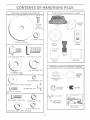
(2} Sheet
Meta
Screws
.t /_os
(i) Locknut 3/8o24
(1) Large Flat Washer
Video
Cassette
'Wheel
Boot
(1) _shou_derBolt 5/16oi8
(_ j Hex Bu ...... .-o,,_x 1
M_.nual
Parts
(!) Lock Washer
bag
Parts Bag
contents
not
shown
fun
size
1/2
(_ _ _,_!_h_ _7/32
x I ,Gi! 6 x t2 Gauge
Wheel
Insert
Steednq When
(2) Lock Washers
(2) Washers
3/16 x 3/4 x 16 Gauge
i% I
(2) oc_ews
(2) Keys
(2) Wetd Nuts #10
#_0 x 5/8
(2) Nex Bolts t/4o20 x 3/4
@
@
(2) Hex Nuts 1/4o20
(2) Lock Washers
(2) Washers
#10
(2} Latch
Hook
Slope Sheet
1/4
9/32 x 5/8 x 16 Gauge
6
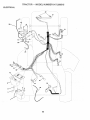
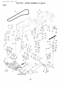
ASSE
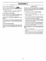
Your new tractor has been assembled at the factory with exception of those parts Ueffunassembted for shipping purposes.
To ensure safe and proper operation of your tractor all parts and hardware you assemble must be tightened securely° Use
the correct too_s as necessary to insure proper tightness.
TOOLS REQUIRED
FOR ASSEMBLY
A socket wrench set will make assembly easier. Standard
wrench sizes are listed.
(1) 5/18" wrench
(1) 3/4" wrench
(2) 7/18" wrenches
Tire pressure gauge
(1) !/2" wrench
Utility knife
(1) 9/16" wrench
(1) pMlips screwdriver
When right or left hand is mentioned in this manual, it
means when you are in the operating position (seated
behind the steering wheel).
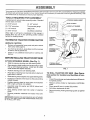
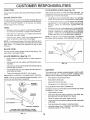
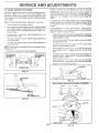
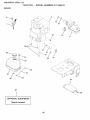
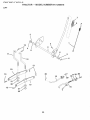
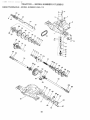
STEERING
BUSHING
/
STEERING
TO REMOVE TRACTOR
UNPACK
FROM CARTON
CARTON
TABS
STEERING
•
Remove alJ accessible loose parts and parts cartons
from carton (See page 8).
,
Cut, from top to bottom, along lines on all four corners
of carton, and lay panels fiat°
•
WHEEL
__
ADAPTER
SHEET
METAL
SCREW
(ASSEMBLY
POSITION)
Check for any additional loose parts or cartons and
remove.
BEFORE ROLLING TRACTOR OFF SKiD
ATTACH
STEERING
WHEEL
(See Fig. 1)
STEERING
(SHIPPING
SHAFT
POSIT!ON)
•
Slide the steering bushing over the steering shaft.
•
Raise steering shaft forward until screw holes in dash
line up with steering bushing. Install two (2) sheet
metal screws and tighten securely.
,
Position steering boot over steering shaft.
•
Place tabs of steering boot over tab slots in dash and
push down to secure.
TO ROLL "'_"""''
n_.,_vn
OFF SKiD (See Operation section for location and function
of con-
,
Slide steering wheel adapter onto upper steering shaft.
trois)
•
Position front wheels of the tractor so they are pointing
straight forward.
,
Press lift lever plunger and raise attachment liftlever to
its highest position.
,
Position steering wheel so cross bars are horizontal
(left to right) and slide onto adapter.
,
Release parking brake by depressing
pedal.
•
Assemble large flat washer and 3/8-24 Iocknut and
tighten securely.
•
,
Place gearshift lever in neutral (N) position.
Roll tractor backwards off skid.
o
Snap steering
wheel
,
Remove banding holding discharge guard up against
tractor.
®
Remove
griH.
FiG. 1
wheel insert into center of steering
protective
materials
from
tractor
hood
and
IMPORTANT:CHECK
FOR AND REMOVE ANY STAPLES
IN SKID THAT MAY PUNCTURE TIRES WHERE TRACTOR
iS TO ROLL OFF SKID.
7
clutch/brake
;E
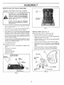
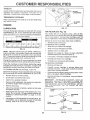
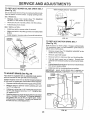
HOW TO SET UP YOUR TRACTOR
CONNECT
BAKERY
(See Figs. 2 and 3)
SEAT
PAN
CAUTION: Do not short battery termio
hats by allowing a wrench or any other
obieet to contact both terminals at the
same time,, Before conneetin 9 battery,
remove meta_ bracelets, wristwatch
bands, rings, etco
BATTERY
BOX DOOR
Positive terminam must be connected
first to prevent sparking from acciden°
tat grounding°
o
Remove cardboard packing from seat pan and tilt seat
pan to raised position.
o
Open battery box door and remove protective ptastic.,
o
Remove terminal protective caps and discard.
o
if this battery is put into service after month and year
indicated on labe_ (label located between terminals)
charge battery for minimum of one hour at 6-10 amps.
FiG. 3
INSTALL
SEAT (See Fig. 4)
Adjust seat before tightening adjustment bolt.
First connect RED battery cable to positive (+) terminal
with hex bo_t, flat washer, lock washer and hex nut as
shown. Tighten securely.
•
Remove cardboard packing on seat pan.
®
o
Connect BLACK grounding cable to negative (-) termina! with remaining hex bolt, flat washer, lock washer
and hex nut. Tighten securely.
o
Place seat on seat pan and assemble shoulder bolt.
Tighten shoulder bait securely.
Assemble adjustment bolt, lock washer and flat washer
loosely. Do not tighten.
•
Close battery box door.
Lower seat into operating position and sit on seat.
Open battery box door for:
•
Inspection for secure connections
ware).
,
inspection for corrosion.
•
Testing battery.
•
Jumping (if required).
o
Periodic charging.
•
Slide seat until a comfortable position is reached which
allows you to press clutch/brake pedal all the way
down.
,
Get off seat without moving its adjusted position.
(to tighten hard-
Raise seat and tighten adjustment bolt securely.
SEAT
SEAT PAN
POSiTiVE
(RED) CABLE
D_SCARD TERMINAL
PROTECTIVE CAPS
HEX
NUT
SHOULDER
BOLT
LOCK
WASHER
FLAT
WASHER
FLAT WASHER
BOLT
ADJUSTMENT
BOLT
NEGATIVE
(BLACK) CABLE
LOCK WASHER
FJGo4
FiG° 2
8
LY
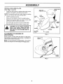
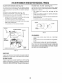
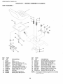
INSTALL
t\,IULCHER
PLATE
NOOK POINTS
(See Figs, 5 and 6)
-
WELD NUT
FROM THE TOP
Install two Jatch hooks to mulcher pBate using screw,
washer, lock washer, and weid nut as shown.
NOTE: Pre-assemble weld nut to latch hook by inserting
weld nut from the top with hook pointing down°
-
Tighten hardware securelyo
®
Raise and hold deflector shield in upright position.
•
Place front of mulcher plate over front of mower deck
opening and slide into place, as shown.
-
Hook front latch into hole on front of mower deck.
-
Hook rear latch into hole on back of mower deck.
LATCH
NOOK
HOOK
WELD
NUT
WASHER
guard when a,aching
muiche,
plate
MULCHER
PLATE
TO CONVERT
DISCHARGING
TO BAGGING
OR
FiG. 5
Simply remove mulcher plate and store in a safe place.
Your mower is now ready for discharging or installation of
optional grass catcher accessory.
DEFLECTOR
SHIELD
NOTE: it is not necessary to change blades. The mulcher
blades are designed for discharging and bagging also.
LATCH
HOOKS
FiG. 6
9
......
ASSE
LY
,/CHECKLIST
CHECK
TmRE
PRESSURE
BEFORE YOU OPERATE AND ENJOY YOUR NEW
TRACTOR, WE WISH TO ASSURE THAT YOU RECEIVE
THE BESTPERFORMANCEAND
SATISFACTION FROM
THIS QUALITY PRODUCT.
The tires on your tractor were ov_rinflat_tbry
for
shipping purposes. Correct tire pressure is impQrtar}t for
best cutting performance.
.....
Reduce tire pressure to PSi shown in "PROE_UCT
SPECIFICATIONS" on page 3 of this manual.
CHECK
DECK
PLEASE REVIEW THE FOLLOWING
LEVELNESS
For best cutting results, mower housing should be properly
_eveted. See "TO LEVEL MOWER HOUSING" in the
Sewice and Adjustments section of this manual.
CHECK
BELTS
FOR
PROPER
POSITION
OF
BRAKE
¢"
All assembly instructions have been completed.
7"
No remaining toose parts in carton.
V" Battery' is properly prepared and charged.
1 hour at 6 amps).
ALL
See the figures that are shown for replacing motion and
mower blade drive belts in the Service and Adjustments
section of this manual. Verify that the belts are routed
correctly.
CHECK
CHECKLIST:
SYSTEM
After you learn how to operate your tractor, check to see
that the brake is properly adjusted. See "TO ADJUST
BRAKE" in the Service and Adjustments section of this
manuai.
(Minimum
/
Seat is adjusted comfortably and tightened securely.
7
All tires are properly inflated. (For shipping purposes,
the tires were overinflated at the factory).
,/
Be sure mower deck is properly leveled side-to-side/
frontoto-rear for best cutting results. (Tires must be
properly inflated for leveling).
,/
Check mower and drive belts. Be sure they are routed
properly around pulleys and inside all belt keepers.
v"
Check wiring. See that all connections are still secure
and wires are properly clamped.
WHILE LEARNING HOW TO USE YOUR TRACTOR, PAY
EXTRA A TTENT!ON TO THE FOLLOWING IMPORTANT
ITEMS:
,/
Engine oil is at proper level.
,/
Fuel tank is filled with fresh, clean, regular unleaded
gasoline.
Become familiar with all controls - their location and
function. Operate them before you start the engine.
,/
¢"
10
Be sure brake system is in safe operating condition.
OPE
0
These symbots may appear on your tractor or in literature supplied with the product. Learn and understand their meaning.
BATTERY
CAUTION OR
WARNING
REVERSE
FORWARD
FAST
SLOW
ENGINE ON
ENGINE OFF
OiL PRESSURE
CLUTCH
LIGHTS ON
OVER TEMP
LIGHT
FUEL
CHOKE
MOWER HEIGHT
DIFFERENTIAL
LOCK
PARKING BRAKE
LOCKED
UNLOCKED
L
REVERSE
MOWER LiFT
IklI:::HTI3AI
ATTACHMENT
CLUTCH ENGAGED
HIGH
LOW
ATTACHMENT
CLUTCH DISENGAGED
PARKING BRAKE
IGNITION
HYDROSTATIC FREE WHEEL
(Hydro Models only)
DANGER, KEEP HANDS AND FEET AWAY
11
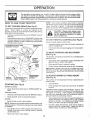
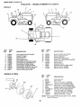
}<NOW YOUR
READ THIS OWNER'S
....
,.,......
MANUAL
AND SAFETY
RULES
BEFORE
OPERATING
YOUR TRACTOR
Compare the illustrations with your tractor to familiarize yourself with the locations of various controls and adjustments.
this manuat for future reference.
Save
LIGHT
SWITCH
LIFT LEVER
PLUNGER
ATTACHMENT
LIFT. LEVER
I\t
MOWER DECK
HEIGHT ADJUSTMENT
POSITIONS
PARKING
BRAKE
GEARSHIFT
LEVER
FIG. 7
Our tractors conform to the safety standards of the American National Standards institute.
ATTACHMENT CLUTCH LEVER: Used to engage the
mower blades, or other attachments mounted to your
tractor.
GEARSHIFT LEVER: Selects the speed and direction of
tractor.
ATTACHMENT LIFT LEVER: Used to raise, lower, and
adjust the mower deck or other attachments mounted to
your tractor.
LiFT LEVER PLUNGER: Used to release attachment lift
LIGHT SWITCH: Turns the headlights on and off.
THROTTLE/CHOKE
CONTROL:
Used for starting and
controlling engine speed.
lever when changing its position.
CLUTCH/BRAKE PEDAL: Used for declutching and braking the tractor and starting the engine.
PARKING BRAKE: Locks clutch/brake pedal into the
brake position.
4
iGNITiON SWITCH: Used for starting and stopping the
engine.
AMMETER: indicates battery charging (+) or discharging
(-),
!2
E
vision safety mask over the spectacles
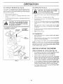
HOW TO USE YOUR TRACTOR
TO SET PARKING
BRAKE
or standard
safety, gmasseso
NOTE: Under certain conditions when tractor is standing
idle with the engine running, hot engine exhaust gases may
cause "browning '_of grass. To eliminate this possibility,
always stop engine when stopping tractor on grass areas.
(See Fig, 8}
Your tractor is equipped with an operator presence sensing
switch, When engine is running, any attempt by the
operator to leave the seat without first setting the parking
brake wil! shut off the engine.
•
Depress clutch/brake pedal into fult "BRAKE" position
and hold.
•
Place parking brake lever in "ENGAGED" position and
pletely, as described above, before leavCAUTION:
Always position;
stop tractor
corno
ing
the operator's
to empty
grass catcher, ere,
TO USE THRO_LE
remain in "BRAKE" position. Make sure parking brake
wil_ hold tractor secure.
ATTACHMENT CLUTCH
"ENGAGED"
POSiTiON
(See Fig° 8)
o
Operating engine at tess than full throttle reduces the
battery charging rate.
o
Fuji throttle offers the best bagging and mower performance.
LEVER
_GNITtON
KEY
TO #OVE
(See
THROTTLE/CHOKE',
CONTROL LEVER
CONTROL
Always operate engine at full throttle.
FORWARD
AND BACKWARD
Fig, 8}
The direction and speed of movement
gearshift tever.
PARKING
BRAKE
"ENGAGED"
is controlled by the
•
Start tractor with clutch/brake pedal depressed and
gearshift lever in neutral (N) position.
,
Move gearshift lever to desired
position.
o Slowly release clutch/brake pedal to start movement.
_MPORTANT: BRING TRACTOR TO A COMPLETE STOP
BEFORE SHIFTING OR CHANGING GEARS. FAILURE
TO DO SO W_LL SHORTEN THE USEFUL LIFE OF YOUR
TRANSAXLEo
"BRAKE"
POSiTiON
CLUTCH/BRAKEPEDAL
"DRWE"POSIT!ON
TO ADJUST
PARKING BRAKE
"DISENGAGED"
POSiTiON
(See Fig. 8)
MOWER BLADES o
Move attachment clutch lever to "DISENGAGED"
sition.
po-
Depress clutch/brake pedal into full "BRAKE" position.
•
Move gearshift
ENGINE =
•
lever to neutral (N) position.
lift lever determines
the
,
Grasp lift lever°
•
Press plunger with thumb and move lever to desired
position.
The average lawn should be cut to approximately 2-1/2
inches during the cool season and to over 3 inches
during hot months. For healthier and better looking
lawns, mow often and after moderate growth.
Move throttle control to slow position.
NOTE: Failure to move throttle control to slow position and
allowing engine to idle before stopping may cause engine
to "backfire".
•
HEIGHT
The cutting height range is approximately 1-1/2 to 4". The
heights are measured from the ground to the blade tip with
the engine not running. These heights are approximate
and may vary depending upon soil conditions, height of
grass and types of grass being mowed.
GROUND DRIVE o
•
CUTTING
The position of the attachment
cutting height.
FiG. 8
STOPPING
MOWER
(See Fig. 8)
,
Turn ignition key to "OFF" position and remove key.
Always remove key when leaving tractor to prevent
unauthorized use.
Never use choke to stop engine.
is
For best cutting performance, grass over 6 inches in
height should be mowed twice. Make the first cut
relatively high; the second to desired height.
TO OPERATE
MOWER(See
TO OPERATE
Fig, 9)
ON H_LLS
Your tractor is equipped with an operator presence sensing switch. Any attempt by the operator tp leave the seat
with the engine running and the attachment clutch engaged
will shut off the engine.
o
Select desired height of cut.
o
Sta_t mower blades by engaging a_achment
control
Choose"
Avoid stopping or changing speed on hilts.
TO STOP MOWER BLADES o disengage attachment
clutch control.
F
_ _
,
"ENGAGED"
POSiTiON
If slowing is necessary, move throttle control lever to
ff stopping is absolutely necessary, push clutch/brake
pedal quickly to brake position and engage parking
brake
CAUTION: Do not operate the mower
without either the entire grass catcher,
on mowers so equipped, or the discharge guard in pla.Ceo
ATTACHMENT CLUTCH LEVER
"DISENGAGED"' POSIT_ON
_c_ speed b_,ore
--_
_he s ow_,_
starting up or down
hills°
ciutch
Move gearshift lever to 1st 9ear. Be sure you have
allowed room for tractor to roll s%hfly as you restart
movement.
ATTACHMENT
LiFT LEVER
HiGH POSITION
To restart movement, slowly release parking brake and
clutch/brake pedat.
Make al! turns slowly.
TO TRANSPORT
Raise attachment lift to highest position with attachment lift control
rt
LOW
POSiTiON
When pushing or towing your tractor, be sure gearshift
lever is in neutral (N) position.
////z
o
Do not push or tow tractor at more than five (5) MPH.
NOTE: To protect hood from damage when transporting
your tractor on a truck or a trailer, be sure hood is closed
and secured to tractor. Use an appropriate means of tying
hood to tractor (rope, cord, etc,).
BEFORE
CHECK
ENG!NE
THE ENGINE
OiL LEVEL
(See Fig. !4)
®
The engine in your tractor has been shipped, from the
factory, already tilled with summer weight oil.
o
Check engine oil with tractor on level ground.
®
Remove oil fill cap/dipstick and wipe clean, reinsert the
dipstick and screw cap tight, wait for a few seconds,
remove and read oil level, if necessary, add oil until
"FULL" mark on dipstick is reached. Do not overfill.
,
For cold weather operation you should change oil for
easier starting (See "OIL VISCOSITY CHART" in the
Customer Responsibilities section of this manual).
D_SCHARGE
GUARD
FiG. 9
STARTING
To change engine oil, see the Customer Responsibilities section in this manual.
14
CUSTOMER
ES
ESPONSIB
TRACTOR
TO SHARPEN
Always observe safety rules when performing any mainte°
Care shouk_ be taken to keep the blade balanced. An
unbalanced blade will cause excessive vibration and eventuat damage to mower and engine°
nar_ceo
BRAKE
OPERATION
TIRES
Maintain proper air pressure in ali tires (See "PROD°
UCT SPEC!FICATIONS" on page 3 of this manual).
o
Keep tires free of gasoline, oil, or insect controt chernicats which can harm rubber.,
o
Avoid stumps, stones, deep ruts, sharp objects and
other hazards that may cause tire damage.
(See Fig. 12)
The blade can be sharpened with a file or on a grinding
wheel Do not attempt to sharpen while on the mower.
if tractor requires more than six (6) feet stopping distance
at high speed in highest gear, then brake must be adjusted.
(See "TO ADJUST BRAKE" in the Service and Adjustments section of this manual)o
o
BLADE
--
To check blade balance, you wit! need a 5/8" diameter
stee_ bolt, pin.°or a cone baiancer. (When using a cone
balancer, fotlow the instructions supplied with baF
o
Stide blade on to an unthreaded portion of the steel b0Jt
or pin and ho_dthe bolt or pin paraJtel with the ground.
If blade is balanced, it should remain in a horizontal
position. If either end of the blade moves downward,
sharpen the heavy end until the btade is balanced.
NOTE: Do not use a nail for balancing blade. The lobes of
the center hole may appear to be centered, but are not.
NOTE: To seal tire punctures and prevent flat tires due to
slow leaks, tire sealant may be purchased from your local
parts deater. Tire sealant also prevents tire dry rot and
CENTER
HOLE
corrosion.
BLADE
CARE
For best results mower blades must be kept sharp.
place bent or damaged blades.
BLADE
o
REMOVAL
Re-
(See Fig. 11)
Raise mower to highest position to allow access to
blades.
Remove hex bolt, lock washer and flat washer securing blade.
Install new or resharpened blade with trailing edge up
towards deck as shown.
FIG. 12
Reassemble hex bolt, lock washer and flat washer in
exact order as shown.
BATTERY
-_ Tighten bolt securely (30-35 Ft. Lbs. torque).
iMPORTANT: BLADE BOLT IS GRADE 8 HEATTREATED.
Your tractor has a battery charging system which is sufficient for normal use. However, periodic charging of the
batter,! with an automotive charger will extend its life.
NOTE: We do not recommend sharpening blade - but if
4ou do, be sure the blade is balanced.
*
Keep battery and terminals clean.
Keep battery bolts tight.
Keep small vent holes open.
o
Recharge at 6-10 amperes for 1 hour.
TO CLEAN BATTERY AND TERMINALS
Corrosion and dirt on the battery and terminals can cause
the battery to "leak" power.
Open battery box door.
TRAiLiNG
EDGE UP
Disconnect BLACK battery cable first then RED battery cable and remove battery from tractor.
Rinse the battery with plain water and dry.
,
Ciean terminals and battery cable ends with wire brush
until bright.
o
Coat terminals with grease or petroleum jelly.
LOCK
FLAT WASHER
WASHER __
_"
Reinstall battery (See "CONNECT
Assembly section of this manual).
HEX BOLT (GRADE 8)*
*A GRADE 8 HEAT TREATED BOLT CAN BE
IDENTIFIED BY SIX LINES ON THE BOLT HEAD.
FiG. 11
18
BATTERY"
in the
ES
ES
VoBELTS
Check V-beJts for deterioration and wear after 100 hours of
operation and replace if necessary. The belts are not
adjustable. Replace belts if they begin to s_ip from wear°
TRANSAXLE
OiL F|LL
CAP/DIPSTICK
OOOUNG
Keep transaxte free from build-up of dirt and chaff which
can restrict cooling.
OiL DRAIN
PLUG
ENGINE
FiG. 14
LUBRICATION
Only use high quality detergent oil rated with API service
classification SF, SG, or SHe Select the oil's SAE viscosity
grade according to your expected operating temperature.
AIR FmLTER (See Fig. 15)
Your engine wi!l not run properly using a dirty air filter.
Clean the foam preocleaner after every 25 hours of operation or every season. Service paper cartridge every 100
hours of operation or every season, whichever occurs first.
SAE VISCOSITY GRADES
T
oF
_C
_20 o
-30 °
0,,
-20 °
TEMPERATURE
30 °
d0 °
32 °
40 °
0°
RANGE ANTICIPATED
60 _
iO °
Service air cleaner more often under dusty conditions.
,
Remove knob(s) and cover.
TO SERVICE PRE-CLEANER
80 °
;0 o
Slide foam preocteaner off cartridge.
BEFORE NEXT OiL CHANGE
,
FiG, 13
Squeeze it dry in a clean cloth.
NOTE: Although multi-viscosity oils (5W30, 10W30 etc.)
improve starting in cold weather, these multi-viscosity oils
will result in increased oil consumption when used above
32°F. Check your engine oit level more frequently to avoid
possible engine damage from running low on oil.
Change the oil after every 25 hours of operation or at least
once a year if the tractor is not used for 25 hours in one year.
Determine temperature range expected before oil change.
All off must meet APJ service classification SF, e_'v"or SH.
Be sure tractor is on level surface.
Oil will drain more freely when warm.
Catch oil in a suitable container.
®
o
o
o
Saturate it in engine oil Wrap it in clean, absorbent
cloth and squeeze to remove excess oi!.
o
tf very dirty or damaged, replace pre=cleaner.
o
Reinstall pre-cieaner over cartridge.
o
TO CHANGE ENGINE OIL (See Figs. 13 and 14)
o
o
o
Reinstall cover and secure with knob(s).
TO SERVICE CARTRIDGE
*
Remove cartridge nut.
Check the crankcase oil level before starting the engine
and after each eight (8) hours of operation. Tighten oil fill
cap/dipstick securely each time you check the oil level
,
Wash it in liquid detergent and water.
Carefully remove cartridge to prevent debris from
entering carburetor. Clean base carefully to prevent
debris from entering carburetor.
Clean cartridge by tapping gently on flat surface, ff very
dirty or damaged, replace cartridge.
Reinstall cartridge, nut, precleaner, cover and secure
with knob(s).
iMPORTANT:
PETROLEUM SOLVENTS, SUCH AS
KEROSENE, ARE NOT TO BE USED TO CLEAN THE
CARTRIDGE. THEY MAY CAUSE DETERiORATiON OF
THECARTRtDGEo DO NOT OIL CARTRtDGE. DO NOT
USE PRESSURIZED
AfR TO CLEAN
OR DRY
CARTRIDGEo
Remove oil fill cap/dipstick. Be careful not to aitow dirt
to enter the engine when changing oil.
Remove drain plug.
After oil has drained completely, replace oil drain plug
and tighten securely.
COVER .....
KNOB
Refil! engine with oil through oil fil! dipstick tube. Pour
slowly. Do not overfill. For approximate capacity see
"PRODUCT SPECiFICATiONS"
on page 3 of this
manual.
CARTRIDGE
NUT
COVER
Use gauge on oil fill cap/dipstick for checking level. Be
sure dipstick cap is tightened securely for accurate
reading. Keep oil at "FULL" line on dipstick.
FOAM
PREoCLEAN_
'
_BABE
19
FiG. 15
CARTRIDGE
PO
CUSTOME
CLEAN
A_R SCREEN
(See Fig, 16}
IN-LiNE
Air screen must be kept free of dirt and chaff to prevent
engine damage from overheating. Clean with a wire brush
or compressed air to remove dirt and stubborn dried gum
fibers°
ENGINE
COOMNG
Remove any dust, dirt. or oi! from engine coo!ing fins to
prevent engine damage from overheating.
Remove screws from blower housing and lift housing
and dipstick tube assembly off engine.
,_
Cover oi! fill opening to prevent entry of dirL
o
Use compressed ar or stiff bristie brush to thoroughly
clean engine cooling fins.
o
To reassemble, reverse above procedure.
BLOWER
FUEL RLTER
(See Fig, 17)
The fuel filter should be replaced once each season, ff fuel
filter becomes clogged, obstructing fuel flow to carburetor,
replacement is required°
FINS (See Fig. 16)
o
IL!T!ES
o
With engine cool, remove filter and plug fuel line
sections.
o
Ptace new fuel filter in position in fuel line with arrow
o
Be sure there are no fuet line leaks and clamps are
properly positioned°
Immediately wipe up any spilled gasoline.
HOUStNG
SCREWS
FIG, 17
CLEANING
Clean engine, battery, seat, finish, etc. of all foreign
matter.
A_R SCREEN
OiL FiLL
TUBE
ASSEMBLY
Keep finished sudaces and wheels free of al! gasoline,
oil, etc.
•
ENGINE COOMNG
We do not recommend using a garden hose to clean your
tractor unless the electrical system, muffler, air filter and
carburetor are covered to keep water out. Waterin engine
can result in a shortened engine life,
SPARK
PLUG
RNS
FiG. !6
MUFFLER
Inspect and replace corroded muffler and spark arrester (if
equipped) as it could create a fire hazard and/or damage.
SPARK
Protect painted surfaces with automotive type wax.
PLUGS
Replace spark plugs at the beginning of each mowing
season or after every 100 hours of operation, whichever
occurs first. Spark plug type and gap setting are shown in
"PRODUCT SPECIFICATIONS" on page 3 of this manual.
20
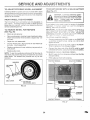
EFIViCE A
CAUTION:
®
*
*
*
,
-=
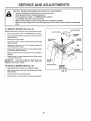
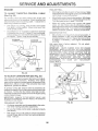
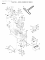
TO REMOVE
ADJ
ENTS
gEFORE PERFORMING ANY SERVICE OR ADJUSTMENTS:
Depress clutc_rbrake pedaJ fully and set parking brake,
Place gearshift _ever in neutra| (N) position,
PWaceattachment clutch in "DISENGAGED" position,
Turn ignition key "OFF" and remove key=
Make sure the blades and aU moving parts have completely stopped,
Disconnect spark plug wire from spark piug and piace wire where it cannot come _n contact with
plug°
MOWER
(See Fig. 18)
CLUTCH
Mower will be easierto remove from the right side of tractor.
*
*
Place attachment clutch in "DISENGAGED" position.
Move attachment lift lever forward to lower mower to its
lowest position,
*
Roll belt off engine pulley.
,
Disconnect clutch rod from clutch lever by removing
retainer spring.
,
Disconnect anti-sway bar from chassis bracket by
removing retainer spring,
*
Disconnect suspension arms from rear deck brackets
by removing retainer springs,
®
Disconnect front links from deck by removing retainer
springs.
SUSPENSION
ARMS
ENGINE
PULLEY
SPRINGS
SLOES)
!
,
Raise lift lever to raise suspension arms. Slide mower
out from under tractor.
iMPORTANT:
iF AN ATTACHMENT OTHER THAN THE
MOWER iS TO BE MOUNTED TO THE TRACTOR,
REMOVE THE FRONT LINKS.
/
RETAINER
SPRING
ANTIoSWAYBAR
TO INSTALL
MOWER
(See Fig. 18)
-
Raise attachment lift lever to its highest position.
•
Slide mower undertractorwith
side of tractor.
•
,
Lower lift lever to its lowest position,
Install mower in reverse order of removal instructions.
LEVER
CLUTCH
discharge guardto right
RETAINER
SPRINGS
(BOTH SIDES)
FIG. 18
21
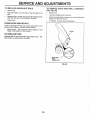
SERVICE AN
TO LEVEL
MOWER
A
HOUSING
FRONT-TO-BACK
Adiust the mower while tractor is parked on level ground or
Make sure tires are property inflated (See
"PRODUCT SPECIFICATIONS" on page 3 of this manuat).
tf tires are over or underinfiated, you will not properly adjust
your mower.
At the midpoint of both sides of mower, measure height
from bottom edge of mower to ground. Distance "A" on
both sides of mower should be the same or within 1/4"
of each other.
o
Jf adjustment is necessary', make adjustment on one
side of mower onty.
(See Figs. 21 and 22)
To obtain the best cutting results, the mower housing
should be adjusted so that the front is approximately
1/8" to
1/2" lower than the rear when the mower is in its ,_<"_'""*,,u,
,_o,
SDEoTO-SIDE ADJUSTMENT (See Figs° I9 and 20)
o Raise mower to its highest positiono
o
ADJUSTMENT
_MPORTANT:
DECK MUST BE LEVEL SIDEoTO-SIDE.
1F
THE FOLLOWING
FRONToTO_BACK
ADJUSTMENT
IS
NECESSARY_ BE SURE TO ADJUST BOTH FRONT LINKS
EQUALLY
SO MOWER
WILL STAY LEVEL SIDE-TOSIDE.
Check adjustment on right side of tractor Measure distance "D" directly in front and behind the mandrel at bottom
edge of mower ho_Jsing as shown°
o
To raise one side of mower, tighten lift link adjustment
nut on that side.
Before making any necessary adjustments, Check that
both front links are equaI in length. Both links should be
approximately 10o3/8"o
o
To lower one side of mower, loosen lift link adjustment
_u_ Ot_that side.
o
NOTE: Each fult turn of adjustment nut will change mower
height about 1/8"o
Recheck measurements after adjusting.
o
If Iinks are not equal in tength, adjust one tink to same
length as other link.
_r_,,
,, ,_owerfront _,f_,
,,,_w_,m_,_
_ !oosen nut "_"_on both front.
links an equat number of turns.
When distance "D" is !/8" to 1/2" lower at front than
rear, tighten nuts "F" against trunnion on both front
links.
BOTTOM EDGE
OF MOWER TO
GROUND
f_h
To raise front of mower, loosen nut"F" from trunnion on
both front links. Tighten nut "E" on both front links an
equal number of turns.
When distance "D" is 1/8" to t/2" lower at front than
rear, tighten nut "F" against trunnion on both front links.
BOTTOM EDGE
OF MOWER TO
]/T---_,GROUND
[
Recheck side4o-side adjustment.
\\
GROUND MNE
I
MANDREL
FiG. 19
SUSPENSION
ARM
FIG. 21
BOTH FRONT LINKS MUST BE EQUAL iN LENGTH
[]©
LiFT LiNK
ADJUSTMENT
NUT
FIG. 20
NUT "E"
NUT "F"
FRONT UNKS
22
TRUNNION
F_Go22
ERVICE A
TO REPLACE
(See Fig.23)
MOWER
BLADE
DRIVE
ADJ
BELT
E
W_TN PARKING
BRAKE °'ENGAGED `°
The mower b_ade drive belt may be replaced without tools.
Park the tractor on levemsun'ace. Engage parking brake°
BELT REMOVAL o
*
Remove mower from tractor (See "TO REMOVE
MOWER" in this section of this manual).
*
Work belt off both mandrel pulleys and idler pulleyso
*
Pull belt away from mower.
NUT °°A"
BELT INSTALLATION *
Install new be_t in reverse order of removal.
*
Make sure belt is in all pulley grooves and inside aHbeJt
guides.
Install mower in reverse order of removal instructions.
FIGo 24
MANDREL
PULLEY
ADLER
PULLEYS
TO REPLACE
MOTION
DRWE
BELT
(See Fig.25)
Park the tractor on level surface. Engage parking brake.
For assistance, there is a belt installation guide decal on
bottom side of left footrest.
Remove mower (See "TO REMOVE MOWER" in this
section of this manual.)
\
\
MANDREL
PULLEY
i
*
Remove upper belt keeper.
®
*
Remove bett from stationary idler and clutching idtero
Pul! belt slack toward rear of tractor. Remove belt
upwards from transaxle pulley by deflecting belt keepers.
,
Pull belt toward front of tractor and remove downwards
from around engine pulley.
,
Install new bett by reversing above procedure.
iMPORTANT:
MAKE SURE UPPER BELT KEEPER JS
POSITIONED PROPERLY BETWEEN LOCATOR TABS.
FiG. 23
TO ADJUST BRAKE (See Fig. 24)
Your tractor is equipped with an adjustable brake system
which is mounted on the right side of the transaxle.
TABS
ff tractor requires more than six (6) feet stopping distance
at high speed in highest gear, then brake must be adjusted.
,
Depress clutch/brake pedal and engage parking brake.
*
Measure distance between brake operating arm and
nut "A" on brake rod.
UPPER BELT
KEEPER
iDLER
if distance is other than 1-1/2", loosen jam nut and turn
nut "A" until distance becomes 1-1/2". Retighten jam
nut against nut "A'.
PULLEY
Road test tractor for proper stopping distance as stated
above. Readjust if necessary. If stopping distance is
still greater than six (6) feet in highest gear, further
maintenance is necessary. Contact your nearest au o
thorized service center/department.
FJGo 25
23
TO ADJUST
STEERING
WHEEL
ALIGNMENT
_fsteering whee_ crossbars are not horizontal (left to right}
when wheels are positioned straight fosoe_a_d_
remove steering wheel and reassemble per instructions in the Assembly
section of this manual.
FRONT
WHEEL
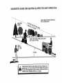
TO START ENG_N_I: WITH A WEAK
See Fig. 27}
CAUT_O_S: L÷adoecid batteries genero
ate exp_os_ve.{_aseso Keep sparks° flame
ahd smoki_9 materials away from bat°
teri®so Atways wear eye protection
whe_ aro_d
batteries.
TOE4NiCAMBER
The front wheei toe-in and camber are not adjustable on
your tractor. _f damage has occurred to affect the front
wheel toeoin or camber, contact your nearest authorized
service center/departmento
TO REMOVE WHEEL
(See Fig. 26)
FOR REPAIRS
Block up axle securely,
Remove axle cover, retaining dng and washers to allow
wheel removal (rear wheet contains a square key - Do
not lose}.
if your battery
starting,
TO ATTACH JUMPER CABLES o
o
Connect each end of the RED cable to the POSITIVE
(+) termina_ of each bates/taking
care not to short
against chassis,,
Connect one end of the BLACK cable to the NEGATIVE (o} terminal of fuly charged battery°
o
Connect the other end of the BLACK cable to good
CHASSIS GROUND, @_'ayfrom fuel tank and battery.
On rear wheels only: align grooves in rear wheel hub
and axle. _nsert square key.
o
Replace axle cover.
NOTE: To seal tire punctures and prevent flat tires due to
slow !eaks, tire sealant may be purchased from your !ocal
3arts dealer. Tire sealant also prevents tire dry rot and
TO REMOVE CABLES
o
o
_orrosion,
is too weak to start the engine, it should be
tf it_mper cabes"
are used for emergency
follow ths procedure:
_r_PORTANT: YOUR TRACTOR _S EQUIPPED WITH A !2
VOLT NEGAT!V_
GROUNDED
SYSTEM,
THE OTHER
VEHICLE
MUST
ALSO BE A 12 VOLT
NEGATIVE
GROUNDED
SYSTEM
DO NOT uSE YOUR TRACTOR
BATTERY TO START OThiER VEH_CLESo
Repair tire and reassemMeo
Replace washers and snap retaining ring securely in
axle groove_
BATTERY
REVERSE ORDER -
BLACK cable first fore chassis and then from the fully
charged battery°
RED cable last from both batteries,
POSITIVE TERMINAL
NEGATIVE
TERMINAL
WASHERS
RETAINING
R_NG
AXLE COVER
'_
SQUARE
KEY
{REAR WHEEL ONLY}
NGo 26
CABLES
_CHARGED
BATTERY
POSITIVE TERMINAL
NEGATIVE
FIG, 27
TERMINAL
SERVICE
TO REPLACE HEADLIGHT
ADJUSTM
TO REMOVE
BULB
HOOD AND GRILL
ASSEMBLY
,
Raise hood.
(See Fig. 28)
o
Pul! bulb holder out of the hole in the backside of the
grill
,
Raise hood.
,
Unsnap headlight wire connector.
Replace bulb in holder and push bulb holder securely
back into the hole in the backside of the grill
Close hood.
,
Stand in front of tractor. Grasp hood at sides, tilt toward
engine and lift off of tractor.
,,
To replace, reverse above procedures.
o
•
iNTERLOCKS
AND RELAYS
Loose or damaged wiring may cause your tractor to run
poorly, stop running, or prevent it from starting.
=
Check wiring. See electrical wiring diagram in the
Repair Parts section of this manual.
TO REPLACE
FUSE
Reptace with 30 amp automotive-type plug-in fuse. The
fuse holder is located behind the dash.
HEADLIGHT
WiRE
CONNECTOR
FiG. 28
25
SE
ADJ
FINAL SETTING o
TO ADJUST
THROSTLE
CONTROL
CABLE
o
Sta_ engine and allow to warm for five minutes. Make
final adjustments with engine running and shiftJmotion
contra_ Iever n neutra_ (N) pesitiono
o
Move throttle contrel lever to slow position. With finger,
rotate and ho!d throttle lever against idle speed screw°
Turn id;e speed screw to attain 1750 RPM.
o
Whi!e still ho!ding throSte lever against idle speed
screw, turn idte mixture valve in (clockwise) until eric
gine begins to die and then turn out (counterclockwise)
until engine runs rough. Turn valve to a point midway
between those two positions. Release throttle tevero
(See Fig. 29)
The throttle control has been preset at the factory and
adiustment shouhJ _sotbe necessary. Check adjustment as
described be!ow before !oesening cable. _fadjustment is
necessary, p_oceed as foIIows:
o
With ensirse not running, move th_ott!e controt lever
from slow to choke position. Stow!y move lever from
choke to fast position°
o
Check that ho_es"A" in governor control lever and hole
in governor plate !ineoup. _fholes "A" are not aligned,
loosen ctamp screw and move throttle cable unti_ holes
are atignedo Tighten ctamp screw securely,
GOVERNOR
CONTROL LEVER
ACCELERATION
o
GOVERNOR
CONTROL PLATE
I
HOLES "A"
-
High speed stop. is factory
damage may result.
aajus_eu_............
uu not adjust
J
THROTTLE
CLAMP
SCREW
iDLE SPEED
SCREW
THROTTLE
CABLE
FIG. 29
TO ADJUST
CARBURETOR
(See Fig, 30)
'The carburetor has been preset at the factory and adjustment should not be necessary. However, minor adjustment may be required to compensate for differences in fuel,
temperature, altitude or load. If the carburetor does need
adiustment, proceed as follows:
In general, turning idle mixture valve in (clockwise) decreases the supply of fuel to the engine giving a leaner fuel/
air mixture. Turning the idle mixture valve out (counterclockwise) increases the supply of fuel to the engine giving
a richer fuel/air mixture.
IMPORTANT:
DAMAGE TO THE NEEDLE
THE SEAT IN CARBURETOR
MAY RESULT
TURNED IN TOO TIGHT,
PRELIMINARY
VALVE
AND
IF SCREW IS
iDLE MIXTURE
VALVE
FiG. 30
SETTING -
Air cleaner assembly must be assembled to the carburetor when making carburetor adjustments.
o
=
iMPORTANT:
NEVER TAMPER
W_TH THE ENGINE
GOVERNOR,
WHICH IS FACTORY SET FOR PROPER
ENGINE SPEED. OVERSPEEDING
THE ENGINE ABOVE
THE FACTORY
HIGH
SPEED
SETTING
CAN
BE
DANGEROUS.
IF YOU THINK THE ENGINE-GOVERNED
HIGH SPEED NEEDS ADJUSTING,
CONTACT
YOUR
NEAREST
AUTHORIZED
SERVICE
CENTER/
DEPARTMENT,
WHICH HAS PROPER EQUIPMENT
AND
EXPERIENCE
TO
MAKE
ANY
NECESSARY
ADJUSTMENTS.
\
\
TEST
Move throttle cor_trol lever from slow to fast position. If
engine hesitates or dies, turn idJe mixture valve out
(counterctockw
se) 1/8 turn Repeat test and continue
to adjust,
if necessary,
untif engine
accelerates
smoothly.
Be sure the throttle control cable is adjusted properly
(see above).
With engine off turn idle mixture valve in (clockwise)
closing it finger tight and then turn out (counterclockwise) 1 full turn.
26
STORAGE
ENGINE
mmmediately prepare your tractor for storage at the end of
the season or if the tractor will not be used for 30 days or
more.
ab_iding
_-each
an open flame
or spark. Al|ow the engine to cooJ
before storing in any enciosureo
FUEL SYSTEM
1
TRACTOR
iMPORTANT:
_T IS _MPORTANT
TO PREVENT
GUM
DEPOSITS
FROM FORMING
tN ESSENTIAL
FUEL
SYSTEM PARTS SUCH AS CARBURETORs
FUEL F_LTER_
FUEL HOSE, OR TANK DURING
STORAGE°
ALSO
EXPERIENCE
_ND_CATES THAT ALCOHOL
BLENDED
FUELS (CALLED
GASOHOL
OR USING ETHANOL
OR
METHANOL)
CAN ATTRACT MOISTURE
WHICH LEADS
TO SEPARATION
AND FORMATmON OF AODS DURING
STORAGE.
ACIDIC
GAS CAN DAMAGE
THE FUEL
SYSTEM OF AN ENGINE WHILE _N STORAGE°
Drain the fuel tank.
Remove mower from tractor for winter storage. When
mower is to be stored for a period of time, clean it thorougHy, remove all dirt, grease, leaves, etc. Store in a
clean, dry area.
-
Clean entire tractor (See"CLEANING" in the Customer
Responsibilities section of this manual).
,
inspect and replace belts, if necessary (See beit replacement instructions in the Service and Adjustments
section of this manual).
o
Lubricate as shown in the Customer Responsibilities
section of this manual.
Star the engine and let it run until the fuel lines and
carburetor are empty.
Never use engine or ca_uretor cleaner products in the
fuel tank or permanent damage may occur.
Use fresh fueJ next season.
NOTE: Fuel stabilizer is an acceptable aJternative in
minimizing the formation of fuel gum deposits during storo.
age. Add stabilizer to gasoline in fueJ tank or storage
container. Always fottow the mix ratio found on stabilizer
container. Run engine at least t0 minutes after adding
stabilizer to allow the stabilizer to reach the carburetor° Do
not drain the gas tank and carburetor if using fue! stabilizer°
Be sure that all nuts, bolts and screws are securely
fastened. Inspect moving parts for damage, breakage
and wear. Replace if necessary.
,
ENGINE OIL
Touch up all rusted or chipped paint surfaces; sand
lightly before painting.
Drain oi! (with engine warm) and replace with clean engine
oil. (See "ENGINE" in the Customer Responsibiiities
section of this manual)°
BATTERY
®
Fully charge the battery for storage.
*
After a period of time in storage, battery may require
recharging.
-
o
*
CYLINDERS
Remove spark plug(s).
To help prevent corrosion and power leakage during
long periods of storage, battery cables should be
disconnected and battery cleaned thoroughly (see 'q'O
CLEAN BATTERY AND TERMINALS" in the Customer Responsibitities section of this manual).
o
Pour one ounce of oil through spark plug hole(s) into
cylinder(s).
o
Turn ignition key to"START" position for a few seconds
to distribute oil.
Replace with new spark plug(s).
After cleaning, leave cables disconnected and place
cables where they cannot come in contact with battery
terminals.
OTHER
Be sure battery drain tube is securely attached.
o
Do not store gasoline from one season to another.
If battery is removed from tractor for storage, do not
store battery directly on concrete or damp surfaces.
®
Replace your gasotine can if your can starts to rust.
Rust and/or dirt in your gasoline wilJ cause probiemSo
o
If possible, store your tractor indoors and cover it to
give protection from dust and dirt.
Cover your tractor with a suitable protective cover that
does not retain moisture. Do not use plastic. P!astic
cannot breathe which allows condensation to form and
will cause your tractor to rust.
IMPORTANT: NEVER COVER TRACTOR WHILE ENGINE
AND EXHAUST AREAS ARE STILL WARM.
27
PO
PROBLEM
CAOSE
WiiJ not start
CORRECTION
Out of fuel
I .
F! fue_tank.
2.
3.
4.
5.
6.
7o
Engine not "CHOKED _ properly.
Engine floc.Jed.
Bad spark plug.
Dirty air filter.
Dirty fue_ filter°
Water ir_ fuel
2
3
4.
5.
6.
7.
8.
9.
Loose or damaged wiring
Carburetor out of adjustment.
8.
9.
See "TO START ENGINE" in Operation section.
Wait s÷ve_al minutes befora attempting to start.
R÷ptace spark ptug.
Clean!replace air rifler.
Rap!ace fuel filter°
Drain fue_ tank and carburetor, refill tank wibh fre_
gasotine a4sd replace fideJfi!ter.
Check al_wiring.
See '%o Adjust Carburetor _ in Service Adjustments
section.
10.
Hard to start
_'_.......
Engine valves out of adiustment,
10_
Contact an authorized service center/depa_mento
I.
2.
3_
4.
5.,
6.
7.
Di_y air fitter.
Bad spark plug.
Weak or dead battery,
Dirty fuel fiffer.
Sta_e or dirty fuel
Loose or damaged wiring.
Carburetor out of adjustment.
1.
2_
3.
4.
5.
6.
7.
C_ean/rep_ace air fil_er.
Replace spark plug.
Rec}a_ge or replace battery.
Replace fuel rifler.
Drain fue} tank and rdiit with fresh gasoUne.
Check a_ wiring.
See "To Adjust CarburetoK' in Service Adjustments
section
8.
Engine valves out of adjustment.
8.
Contact an authorized
1.
2.
3.
4.
Clutch/brake pedal not depressed.
Attachment clutch is engaged.
Weak or dead battery.
Blown fuse.
5.
6.
7.
8.
9.
Corroded batten/terminals.
Loose or damaged wiring.
Faulty ignition switch.
Fault/solenoid
or starter.
Faulty operator presence switch(as).
1.
2.
3.
4,
5.
6.
7.
8.
9.
Depress c_utch/brake pedal
Disengage attachment clutch.
Recharge or replace battery.
Replace fuse.
CIean battery terminals.
Checkall wiring.
ChecWrepiace ignition switch.
ChecWrep_ace solenoid or stader.
Contact an authorized service center/department.
Engine c_icksbat wiB not
start
1.
2.
3.
4.
Weak or dead battery.
Corroded battery terminals.
Loose or damaged wiring.
Faul_ solenoid or starter.
1.
2.
3.
4.
Recharge or replace battery.
Ctean battery terminals.
Check all wiring.
Check/replace solenoid or starter.
Loss of power
1.
2.
3.
4.
5.
6.
7.
8.
9.
Cutting too much grass/too fast.
Throttle in "CHOKE" position.
Build*up of grass, leaves and trash under mower.
Dirty air filter.
Low oil level/dirty oil.
Faulty spark plug.
Dirty fuet filter.
Stale or dirty fue!.
Water in fuel
1.
2.
3.
4.
5.
6.
7.
8
9.
Set in "Higher Cut" position/reduce speed.
Adjust throttle control.
Clean underside of mower housing.
Clean/raplace air filter:
Check oil level/change oil.
Clean and regap or change spark plug.
Replace fue! filter.
Drain fuel tank and refill with fresh gasoline.
Drain fue! tank and carburetor, refill tank with fresh
gasoline and repJace fuel filter.
Connect and tighten spark plug wire.
Clean engine air screen/fins.
Clean!replace muffler.
Checkall wiring.
See 'q'o Adjust Carburetor" in Service Adjustments
section.
Engine
will not turn over
=
Excessive
vibration
-
service center/department.
......
10.
1I_
!2.
13.
14.
Spark plug wire loose.
Dirty engine air screen/fins.
Dirty/dogged muffler.
Loose or damaged widng.
Carburetor out of adjustment.
10.
11.
12.
13.
14.
15.
Engine valves out of adjustment.
15.
Contact an authorized service center/department.
I.
2.
Worn, bent or loose blade.
Bent blade mandrel.
1.
2.
Replace blade. Tighten blade bolt.
Replace blade mandrel.
3,
Loose/damaged
3.
Tighten loose part(s).
part(s).
28
Replace damaged
parts.
TROUBLESHOOTING
POINTS
PROBLEM
CAUSE
CORRECTION
Engine continues to run
when operator Jeaves seat
with attachment clutch
!o
Faulty operator-safety
i.
2.
3.
4.
Worn, beet or loose blade.
Mower deck not teveL
Buildup of grass, leaves, and trash under mower.
Sent btede mandrel.
5.
Clogged mower deck vent holes from buildup of
grass, leaves, and trash around mandrels.
Mower blades will not
rotate
1.
Obstruction
2.
3.
4.
Worn/damaged mower drive belt.
Frozen idler pulley.
Frozen blade mandrel.
Poor grass discharge
I.
2.
3.
4.
Engine speed too sieve.
Travel speed too fast.
Wet grass.
Mower deck not level
1.
2.
3.
4.
Race throttle control in "FAST" position.
Shift to slower speed.
Allow grass to dry before mowing.
Level mower deck.
5.
6.
7.
8.
Low/uneven tire air pressure.
Worn, bent or loose blade.
Buildup of grass, leaves and trash under mower.
Mower drive belt worn.
9.
t0.
1!.
Blades improperly installed.
Improper blades used.
Clogged mower deck vent holes from buildup of
grass, leaves, and trash around mandrels.
presence centre! system.
1.
Check wiring, switches and cennectienso ff not
corrected, contact an authorized service center/
department.
t.
2,
3.
4.
5.
Replace btade. Tighten blade boJt.
Levei _wer
deck.
Clean underside of mower housing.
Replace blade mandrel
Clean around mandrels to open vent holes.
1.
Remove obstruction.
2.
3.
4.
Replace mower drive beJto
Replace idler pulleyo
Replace blade mandrel
engaged
Poor
cut
_ uneven
Headlight(s) not working
(if so equipped)
Battery will not charge
Engine "backfires"
when turning engine
"OFF"
in clutch mechanism.
i.
Switch is "OFF".
2.
3.
4.
5.
Bulb(s) burned out.
Faulty light switch.
Loose or damaged wiring.
Blown fuse.
1.
2.
Bad battery cell(s).
Poor cable connections.
3.
4.
Faulty regulator (if so equipped).
Faulty alternator.
1.
Engine throttle control not set at "SLOW"
position for 30 seconds before stopping engine.
29
5.
6.
7.
8.
9.
10.
lt.
Check tires for proper air pressure.
Replece/sharpen blade. Tighten blade bolt.
Clean underside of mower housing.
Replace mower drive belt.
Reinstall blades sharp edge down.
Replace with blades listed in this manual.
Clean around mandrels to open vent hotes.
1.
2.
3.
4.
5.
Turn switch "ON".
Replace bulb(s).
Check/replace light switch.
Check wiring and connections.
Replace fuse.
1.
2.
3.
4.
Replace battery.
Check/clean all connections.
Replace regulator.
Replace alternator.
1.
Move throttle control to "SLOW" position and a!!ow
to idJefor 30 seconds before stopping engine.
RVICE NOTES
3O
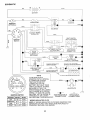
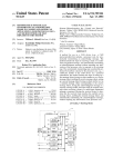
SCHEMATIC
BLACK
RED
BATTERY
CPLP
RED
RED
FUSE 30 AMP.
AMMETER
(OPTIONAL)
STARTER
BLACK
Jr
I
WHITE
J
SOLENOID
I
WHITE
i
(PEDAL UP)
SEAT SW_TCH
(NOT OCCUPIED}
IGNiTiON
SWITCH
WHITE
t
_
U
BLACK
.,'-_
i
I
t
t
j
_
_
I
1
I
t
I
_
-'1
,
BLAC K
NT C
(CLUTCH OFF)
["
1
a
GROUNDING
CONNECTOR
J
J
METER
t
J
(OPTIONAL)
SPARK
r
, BLUE
I
t
I
UNIT
_/,.___*
FUEL=
//X_ LINE I
I
CHARGING SYSTEM OUTPUT
3 AMP DC @ 3600 RPM
I
FUEL SHUT-OFF
SOLENOID
J
{IP
GAP O----4D
BLACK
LIGHTING
SYSTEM
(2PLUGS ON
TWIN CYLo ENG_NESL___
28 VOLTS AC MIN. @ 3600 RPM
(CHARGING SYSTEM DISCONNECTED)
_
I
ALTERNATOR
I i,
ORANGE
t
l___
j
NOTE
IGNITION SWITCH
POSITION
"MAKE"
YOUR TRACTOR IS
EQUIPPED WITH A SPECIAL
BROWN
ALTERNATOR SYSTEM.
THE LIGHTS ARE NOT
CONNECTED TO THE
BATTERY, BUT HAVE THEIR
OWN ELECTRICAL SOURCE.
BECAUSE OF THIS, THE
BRIGHTNESS OF THE LIGHTS
WILL CHANGE WITH ENGINE
SPEED. AT IDLE THE LIGHTS
_,
WILL DIM. AS THE ENGINE IS
NON-REMOVABLE
SPEEDED UP, THE LIGHTS
CONNECTIONS
WILL BECOME THEIR BRIGHTEST,
HEADUGHTS
©
REMOVABLE
CONNECTIONS
r
OFF
RUN/LIGHT
RUN
START
G+M+LI
B+L
NONE
I
A+Y
B+L
NONE
B+L+S
NONE
WIRING INSULATED CLIPS
NOTE: IF WIRING INSULATED CLIPS WERE REMOVED FOR
SERVICING OF UNIT, THEY SHOULD BE REPLACED TO
PROPERLY SECURE YOUR WIRING.
31
7
TRACTOR
o o MODEL NUMBER_ 9!7:2585!5
ELECTRICAL
/
/
/
/
/
!
f
\
I
I
33
32
32
nF,,;;,r_wQ,|F3t, rl,_i=li_
| _;_
TRACTOR
o o MODEL NUMBER
91'7.258515
LECTRICAL
KEY
NO.
1
2
3
4
6
7
8
9
15
!6
1£
20
21
22
24
25
26
28
29
30
31
32
33
40
41
42
43
44
45
52
70
PART
NO.
144925
747604!2
STD551025
STD551125
STD541025
109238X
156417
109596X
147688
153664
STD551125
73350400
136850
4152J
4799J
146147
108824X
4207J
121305X
140301
124211X
141226
109310X
156442
71110408
131563
145673
73640400
121433X
141940
140422
NOTE;
DESCRiPTiON
BattePy 12 Volt 25 AMP
Bott Hex Hd 1/4°20unc X 3/4
Washer 9/32 X 5/8 X 16 Ga
Washer Lock Hvy Helical 1/4
Nut Fin Hex 1/4-20 Unc
Tube Plastic 12"
Case Battery
Clamp Hose Olive
Fastner Snap-In
Switch Inter!ock Push-in
Washer Lock 1/4
Nut Jam Hex 1/4-20 Uric
Harness Socket Light W/4152J
Bulb Light #1156
Cable Battery 6ga 11" red
Cable Battery 6 Ga W/16 Wit red
Fuse 30 AMP Auto Green
Cable Ground 6ga 12" black
Switch Plunger Nc Gray
Switch Ign 4 pos
Nut Ignition
Cover Sw ignition
Key Ign Molded Craftsman, Delta
Harness Man CI Am Hm 97
Bolt BIk Hex t/4-20unc x !/2
Cover Terminal Red
Solenoid
Nut Keps BIk Hex 1/4-20 Unc
Ammeter Rectangular 6 AMP
Protection Wire Loop
Harness Engine, Dual 14 OHV
All component dimensions
1 inch = 25.4 mm
33
•
given in U.S. inches
TRACTOR
CHASSIS
° o MODEL NUMBER
9!7o2585!5
AND ENCLOSURES
30
17
5
18
26
i
31
1
14
140
28
14 _.._
/
33
10
3
14
34
TRACTOR
o o MODEL NUMBER
917.258515
CHASSm$ AND ENCLOSURES
KEY
NO,
t
2
3
4
5
6
7
8
9
10
11
13
14
!5
16
!7
18
19
2'1
22
24
25
26
27
28
29
30
3!
33
34
35
37
38
39
100
140
145
--
PART
NOo
159530
140356
17490612
STD551025
155272
t55924X015
126842X
155138
t56275X0!0
STD533710
155927
!55934X010
174906O8
7418O512
STD541431
154988X574
126938X
17521312
122933X
124479X
STD523710
19131312
STD541437
17030814
14O137
124029X
109872X574
136619
!45244X574
145243X574
STD533707
17490508
139886
139887
105037X
158418
156524
5479J
NOTE:
DESCRIPTION
Chassis Wldmt
Drawbar Stretch
Screw Thdrot 3/8=! 6 x 3/4 Ty-tt
Washer 13/32 X 3/'4 X 16 Ga
Bumper Dash Hood
Saddle Slkscr Fit Lt 6sp Peerless
Shield Ht. Hood Kohl/Dia Engine
Clip Retainer Slide On
Dash Slkscr l opc
Bolt Rdhd Sqnk 3/8-!6unc X t
Panel Dash LH
Pane_ S!kscr Dash RH
Screw Thdrot 3/8-16 x !/2 Ty-tt
Screw Mach TRHD 5/16-18 unc x 3/4
Nut Keps 5/16-18 Uric
Hood Asm Pnt Slope Weld Ms-574
Bumper Hood
Screw Sltd Hex Hd W/PI Washer
Rivet Ratchet Nylon
Washer Nylon Blk 28 x 75 x 19
Bolt Fin Hex 3/8-16 unc x i Gr. 5
Washer 13/32 X 13/16 x 12 Ga
Nut Hex Lock W!Ins. 3/8o!6 Uric
Screw Spiderloc Hex Hd #8 x 7/8
Grille Grey
Lens Headlight Bar Clear
Fender Pnt LT Wio Shift
Bracket Fender Repl 109873x
Footrest Pnt Lh
Footrest Pnt Rh
Bolt Rdhd Sht Sqnk 3/8_16 x 3/4
Screw ThdroL 5/16-18 x 1/2
Bracket Asm Pvt LH MWR Rear
Bracket Asm Pvt RH MWR Rear
Strip Foam t8"
Bracket Suspension Front
Rod Pivot Chassis/Hood
Plug Button BIk 359 Dia Choke
All component dimensions
1 inch = 25.4 mm
35
given in U.S. inche
DRIVE
TRACTOR
" " MODEL NUMBER 917,258515
27
36
W!-i'IW
_ U _
TRACTOR
-o MODEL NUMBER
917o25851,5
DRIVE
KEY
NO=
2
3
4
5
6
7
8
10
I|
12
13
14
15
18
19
21
22
24
25
26
27
28
29
30
31
32
34
35
36
37
38
39
40
PART
NO.
146682
123666X
12000028
121520X
17490512
130802
131679
STD561210
IUO/UIA
19151216
74550412
STD551125
74490544
STD523710
STD541437
106933X
130804
STD541237
I06888X
STD551037
STD561210
145204
124236X
130807
127275X
STD523107
155071
120183X
STD551062
1572H
123674X
STD523727
4470J
DESCRIPTION
Transaxle (See Breakdown)
Dana Mode_ 4360-113
Spring Return Brake T/a Zinc
Pulley Transaxle 18/20" tires
Ring Retainer # 5100_62
Strap Torque 30 Degrees
Screw Thdro{ 5/t6-t8 X 3/4 TYT
Bracket Saddle Shift T!a
Rod Shf Sdt LYfYT Str BIk Zinc
Pin Cotter !/8 X 1 Cad
Washer Plate Shf 388 ou_'nu,_u^'^
Washer 15/32 X 3/4 X 16ga
Bolt 1/4-28unf Gr8 W/Patch
Washer Lock Hvy Helical 1/4
Bolt Hex FLGHD5/16-18Gr.5
Bolt Fin Hex
Nut Lock Hex W/Ins. 3/8-16 Uric
Knob Rd 1/2-13 PIstc Thds BIk
Rod Brake BIk Zinc 26 840
Nut Hex Jam 3/8-16 Unc
Spring Rod Brake 2 00 Zinc
Washer 13/32 X 13/16 X t 6 Ga
Pin Cotter 1/8 X 3/4 Cad
Rod Brake Parking Lt/Yt
Cap Brake Parking Red
Bracket Mtg Transaxle
Keeper Belt LH LT !4 Ga
Bolt Hex Hd 5/16-18unc X 3/4
Shaft Asm Pedal Foot
Bearing Nylon BIk 629 Id
Washer 21/32 X 1 X 16 Ga
Pin Roll 3/16 X 1"
Pulley Idler Fiat
Bolt Fin Hex 3/8-16unc X 2-3/4
Spacer Split 395 X 59 Bzp
KEY
NOo
PART
NO.
41
42
47
48
49
50
51
52
53
55
56
57
58
59
61
62
63
64
65
66
70
72
74
75
76
77
78
112
116
118
121
154777
19131312
t27783
154604
123205X
STD523715
STD541374
STD541431
t05710X
t05709X
_Tr_=,_o-_,_
130801
127274X
140312
17490612
8883R
140186
71170764
STD551143
!54778
134683
19132012
t09502X
121749X
STD581075
123583X
121748X
19091210
72110610
154774
154419
NOTE:
37
DESCRIPTION
Keeper Be_t _dler
Washer t 3/32 X 13/16 X 12 Ga
Pulley Idter V Groove Plastic
BeHcrank Asm Clutch
Nut Crowniock 3/8ot6 UNC
Nut Crown Lock 5/t6o18
Link Clutch 7 66
Spring Return CJutch 6 75
_,_,,t Fin Hex 3/8q6 _n,. ,, ,-,,-_
VoBeit Gd Drive 95 25
Keeper Belt RH LT Pnt/zinc 16g
Keeper Belt Centerspan
Screw Thdrot 3/8-I 6x3/4 Tyott
Cover Peda_ B!k Round
Pulley Eng CI Mech 38deg LT/YT
Bolt Hex 7/16-20x4 Gr 5
Washer Lock Hvy Hlcl Spr 7/16
Keeper Be!t Engine
Guide Belt Mower Drive RH
Washer 13/32 X 1-t/4 X 12 Ga
Spacer Axle
Washer 25/32 X 1 1/4 X 16 Ga
Eoring #5133-75
Key Square2 0 X 1845/1865
Washer 25/32 X 1o5/8 X 16ga
Washer 9/32 X 3/4 X 10 Ga
Bott Rdhd Sq Neck 3/8o16 x 1.25
Spacer Bellcrank
Nyliner Clutching Stl
All component dimensions given in U.S. inches.
1 inch = 25.4 mm
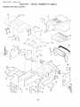
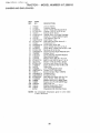
TRACTOR
STEERING
: : MODEL
NUMBER
ASSEMBLY
41
i
i
't
_ ....
42
62
47
\
38
9!7.258515
M!I_IP'I,_IM
t"7,_M
!
TRACTOR
STEERING
o o MODEL
NUMBER
917o25851,5
ASSEMBLY
KEY
NO.
PART
NO.
1
2
3
4
5
6
7
8
9
10
11
!3
15
17
18
19
20
22
23
25
26
27
28
29
30
32
36
37
38
39
40
41
42
43
46
47
53
62
65
66
67
68
69
70
139768
154427
t56483
157473
6266H
121748X
19272016
12000029
3366R
156438
10040600
154779
73901000.
156545
57079
124035X
126684X
71200410
127501
154406
!26847X
136874
19131416
17490612
STD561210
130465
155099
152927
139769
19133808
STD541537
104820X
124417X
!2!749X
121232X
6855M
73680600
156593
154780
154404
74781044
154429
160367
74780636
NOTE:
DESCRPTmON
Wheel Steering Opp Sears Bik
Axle Asm Front Lt
Spindle Asm Lh
Spindle Asm Rh
Washer Thrust .75 x !.230
Washer 25/32 x 1-5/8 x 16 Ga.
Washer 27/32 x tol/4 x 16 Ga.
RingKlip #T5304-75
Bearing Cot Strg BIk
Draglink Extended Stamped
Washer Lock Hvy Htc_ Spr 3/8
Bearing Ax!e
Locknut Flange 5/8ql UNC
Shaft Asm Strg 5/8 x 15.19 Lt
Washer Thrust .515 x .750 x .033
Support Shaft
Washer Shim 1/4 x 5/8 x .062
Screw Hex Socket t/4-20 x 5/8
Shaft Asm Pitman
Bracket Steering
Bushing Link Drag BIk LR
Gear Sector 22 Teeth
Washer !3/32 x 7/8 x 16 Ga°
Screw Thdrot 3/8-16 x 3/4 TY-TT
Pin Cotter 1/8 x 3/4 Cad
Rod Tie Wire Form 19.75 Mech
Bushing Strg. 5/8 JD Dash
Screw
Cap Wheel Steer Opp Sears USA
Washer !3/32 x 2-3/8 x 8 Ga.
Locknut Center 3/8-24 Unf
Adaptor Wheel Strg..640/.635
Id
Boot Shaft Steering Craftsman
Washer 25/32 x !-!/4 x !6 Ga.
Cap Spindle Fr Top BIk
Fitting Grease
Nut Crownlock 3/8-16 Unc
Steering Assembly
Spacer Axle
Bearing Arm Pittman
Bolt Fin Hex 5/8-11 UNC x 2-3/4
Brace Axle
Spacer, Brace, Axle
Bolt, Fin Hex 3/8-16 Unc x 2-1/4
All component dimensions
1 inch = 25.4 mm
39
given in U.S. inches
13
4
32_
33
37
31
4O
23
29
\
OPTIONAL
35
EQUIPMENT
Spark Attester
4O
M rn lr"i,_,| Ir_
ENGINE
NO.
1
2
NO. "
! 32759
17720410
.......
4
13
14
15
16
23
29
137352
272293
13280324
13200300
STD551237
158123
137180-
32
33
35
37
38
158990
t23487X
17490512
137040
.......
40
44
46
62
72
78
81
124028X
17490412
19091416
STD551131
71070512
17490620
128861
NOTE:
DESCRIPTION
"; Control Th/ch RH Blk Pdl 15 10
,:_Screw Hex Thd Cut 1/4o20x5/8 T
Engine (See Breakdown)Briggs
Model No 287707o1255oE1
Muffler Exh LT B&S 14HP !O OHV
Gasket Eng t 313 ld Tin Plated
Nipple Pipe 3/8 Npt x 3"
Elbow Std 90 Degree 3/8-18 Npt
Washer Lock Ext Tooth 3/8
ShieJd Browning
Kit Spark Arrestor (Hat Scm)
Tank Fue! Front ! 25
Cap Asm Fuet Sears Vented
Clamp Hose BIk
Screw Thdrol 5/16-!8 x 3/4 TYT
Line Fuel 20"
Plug Oil Drain (Order From Engine
Manufacturer)
Bushing Snap Nyi BIk Fuel Line
Screw Hexwsh Thdro! 1/'4-20 x 3/4
Washer 9/32 x 7/8 x !6 ga
Washer Lock HW Hlct Spr 5/16
Screw Hex Hd Cap 5/16-18 X 3/4
Screw Thdrol 3/8-16xl =1/4 TYTT
Nut Flange !/4-20 Starter Nut
All component dimensions given in U.S. inches
1 inch = 25.4 mm
41
I=lr_rP41,11n
PPltl"lt
II
TRACTOR
o o MODEL NUMBER
9!7.258515
SEAT ASSEMBLY
22
21
i
]
i
I
r
[
12
KEY
NO.
PART
NO.
1
2
3
4
5
6
7
8
9
10
12
13
140122
140551
STD523710
19131610
145006
STD541437
!24181X
17490616
19131614
155925
121246X
121248X
DESCRIPTION
Seat
Bracket Pvt St
Bolt Fin Hex 3/8-16unc X I
Washer Flat 13132 X I X 10 Ga
Clip Push-In Hinged
Locknut He× W/Wsh 3/8-16
Spring Seat Cprsn 2 250 BIk Zi
Screw Thdrol 3/8-16 X 1 Ty-tt
Washer 13/32 X 1 X 14 Ga
Pan Seat
Bracket Mounting Switch
Bushing Snap BIk Nyl 50 Icl
KEY
NO.
PART
NO.
14
15
16
17
21
22
23
24
25
26
72050412
134300
121250X
123976X
153236
STD541431
74780814
19171912
127018X
STD551150
NOTE:
42
DESCRIPTION
Bolt Rdhd Sht Nk 1/4=20x1-1/2
Spacer Split 28x 96 Yel Zinc
Spring Cprsn 1 27 BIk Pnt
Nut Lock 1/4 Lge Fig Gr 5 Zinc
Bolt Shld 5/16-18 Unc
Nut Lock Hex"W/Ins
5/16-18
Bolt Fin He× 1/2-!3 X 7/8 Gr5
Washer 17/32 X 1-3/16 X 12 Ga
Bolt Shoulder 5/16-18 X 62
Washer Lock Hvy Hlcl Spr 1/2
All component dimensions
1 inch = 25.4 mm
given in U.S. inches
MF.t.IP'P&|M
r"P_
u 4_
TRACTOR
o o MODEL NUMBER
9!7,258515
DECALS
19
3
14
7
4
14
1i
7
9
t0
21
5
12
13
2
-1
15
18
KEY
NO,
1
2
3
4
5
6
7
8
9
10
11
12
PART
NO.
156834
273511
160302
160303
150680
133644
142235
140837
128314
149516
156439
4900J
WHEELS&
KEY
NO,
DESCRIPTION
Decal
Decal
Decal
Decal
Decal
Decal
Decal
Decal
Decal
Decal
Decal
Decal
Dash Inst Oper English
HP Engine
Hood RH
Hood LH
Grille Crafts
Maint Cust Sears Domesti
Side Phi Icgold BIk B & S
Brake Parking Saddle
Fender Craftsman White
Battery Dngr/Psn Eng Acme
Danger Fender Eng!span
Clutch/brake English
13
14
15
!8
19
21
=--=o
- -
PART
NO.
146046
150678
160396
156787
150333
131265
145246
145247
1383tl
161467
161468
DESCRIPT!ON
Decal V-.Belt Dr Sch Tractor
Decal Chassis 6sp 42"
Decal VoBeJt Sch
Decal Mower EZ3 Mulch
Decal Cap CNSMR Help Line SRS
Decal Lightbox
Pad Footrest
Fastener Pop in
Decal Handle Lft Height Adjust
Manuai Owners English
Manuat Owners Spanish
TIRES
KEY
NO.
PART
NO.
DESCRIPT_ON
t 59192
Cap Valve Tire
2 65139
Stem Valve
Tire F Ts 15 X 8 0 o 6 Service
3 106222X
4 59904
Tube Front (Service Item Only)
Rim Asm 6 f font White Service
5 106732X427
6 278H
Fitting Grease (Front Wheel Only)
7 9040H
Bearing Flange (Front Wheel Only)
Rim Asm 8" rear White Service
8 106108X427
Tire R Ts 18x8 5-8 C Service
9 124635X
10 7152J
Tube Rear (Service 1tern Only)
11 104757X
Cap Hub Axle 81k 1 50 X 1 00
-144334
Sealant, Tire (10 oz. Tube)
NOTE: All component dimensions given in U.So inches
1 inch = 25.4 mm
5,8
4,10
7
43
'TRACTOR
° o MODEL
NUMBER
9!7.2585!5
LIF'T
7
/
,/
/
5
/
/'
/'
°j
..
/'
/'
\
3
13
2
\
6
/
5
13
19
20
13
1617 18
32
15
13---_
32
44
NJ;=_r-r&ll
iim
_R
m a
TRACTOR
.. o MODEL NUMBER
917.258515
L|FT
KEY
NO.
PART
NO,
!
2
3
4
5
6
7
8
11
12
13
15
16
17
18
19
20
3!
32
159460
159474
t05767X
12000002
19211621
120183X
125631X
!22365X
139865"
139866
STD624008
127218
73350800
130171
73800800
139868
STD624008
140302
73540600
NOTE:
DESCRIPTION
Wire Asm Inner/Sprg W/plunger LT
Shaft Asm Lift
Pin Groove 1 500 Zinc
E Ring #5133-62
Washer PItd 21/32 X 1 X 21ga
Bearing Nylon BIk 629 Id
Grip Handle Fluted BIk
Button Plunger Red
Link Lift LH
Link Lift RH
Retainer Spring
Link Front
Nut Jam Hex !/2-13 Unc
Trunnion BIk Zinc
Nut Lock W/wsh 1/2-13unc
Arm Suspension Rear
Retainer Spring Zinc
Bearing Pvt Lift Spherical
Nut Crownlock 3/8-24
All component dimensions given in U.S. inches
1 inch = 25.4 mm
45
76 z7 <2_'-67
132
34
33
32
102
104 106
105
106--
2!
22
24
25
28
29
,18
18
5
21
19--_
13_
J
46
27
42" MOWER
KEY
NO.
PART
NO.
I
2
3
4
5
6
8
9
t0
11
12
13
144393
STD533107
138017
138440
STD624008
130832
850857
STD55!137
140298
134149
129895
137645
i4
15
16
17
18
19
20
21
22
23
24
25
26
27
28
29
30
31
32
33
34
35
36
37
40
41
43
44
45
46
48
49
50
128774
110485X
140329
72110610
72140505
132827
136888
STD541431
134753
131267
105304X
123713X
110452X
130968
19111016
131491
157722
129963
153535
137266
STD533717
133835
131494
19131318
STD541437
133551
140083
140088
STD624003
137729
133944
155066
131340
KEY
NO.
DESCR|P_ION
PART
NO.
5!
STD541410
52 139888
53 13t845X900
54 133943
55 155046
56 122052X
58 140086
59 141043
67 149846
68 144200
71 142427
72 131870
73 127847
74 121748X
75 12000029
76 128903
77 127845
78 154810
79 127498
8O 153701
81 73350600
82 142028
83 120958X
84 156084
85 72140618
92 STD541437
101 136420
102 71161010
!03 19061216
104 STD551110
105 160793
106 2029J
128 153390
132 19132203
Mower Housing
Bolt
Bracket Assembly,Sway Bar, Front
Bracket Assembly, Sway Bar
Retainer Spring
Arm, Suspension.. Rear
Bolt, Hex 3/8-24 x ! .25 Grade 8
Washer, Lock
Washer, Hardened
Blade, Mulching
Bearing, Ball
Shaft Assembly, Mandrel, Vented
(!nc!udes Key Number 6)
Housing, Mandrel, Vented.
Bearing, Ball, Mandrel
Stripper, Vented Mower Deck
Bolt, Carriage 3/8-16 x 1-1/4
Bott, Carriage 5/16-t8 x 5/8
Bolt, Shoulder
Baffle, Vortex
Nut Crownlock 5/18-18 UNC
Stiffener Bracket
Bracket, Deflector
Cap, Sleeve
Spring, Torsion, Deflector
Nut, Push
Shield, Deflector
Washer 11/32 x 5/8 x 16 Gauge
Rod, Hinge
Screw Thdrol Washer Head
Washer, Spacer
Pulley, Mandrel
Nut, Toplock, Flanged
Bolt
Fastner, Christmas Tree
Pulley, Idler, Flat
Washer 13/32 x 13/16 x 16 Gauge
Nut Crownlock 3/8-16 UNC
Rod, Pivot, with Nibs
Rod, Clutch, Secondary, with Nibs
Guard, Mandrel, L.H.
Retainer
Screw, Thd. Roll 1/4-20 x 5/8
Washer, Hardened
Roller Assembly, Cam Follower
Bolt, Shoulder #10-24 Grade 5
130794
145411
DESCRiPTiON
Locknut
Bolt, Shoulder 5/16o!8 UNC
Arm Assembly, Pad, Brake
Washers Hardened
Arm, Idler
Spacer, Retainer
Spring, Torsion Brakes
Guard, TUV idler
Knob Custom OvaJ
V°Belt
Rod, Clutch, Pdmary, with Nibs
Spring, Return
Arm, Clutch, Secondary
Washer 25/32 x 1-5/8 x !6 Gauge
Ring, Klip
Bott, Shoulder 3/8-!6 UNC x !..44
Keeper, Spring
Lever Asmo Clutch Pri Plm STLT
Bushing, Large, Brass
Spring, Mower Clutch
Nut, Hex Jam 3/8-16 Unc
Trunnion, Adjo
Washer Sintered
Keeper Belt Idler
Bolt Carriage 3/8_t6 x 2ol/4
Nut
Muicher Cover
Screw
Washer #10
Washer, Lock
Latch Assembly, Bagger
Nut, Weld
Washer Felt
Spacer, Washer 13/32 LD. x !-3/8
CoD. x !/4
Mandrel Assembly (Includes Key
Numbers 8-10, 12-15, 31 and 32)
Mower Deck, Complete (Standard
Deck, Order Separately Mulcher
Plate and Gauge Whee!
Components, Key Nos. 101o106
and 111-121)
NOTE: All component dimensions given in UoS. inches
1 inch = 25.4 ram.
47
TRACTOR
DANA
TRANSAXLE
o MODEL
o o MODEL NUMBER
NUMBER
917.258515
4360-113
8
27
32
54
44
45
46
48
49
50
70
48
U _lfm_U
r"_i_
I
W
r_&!
_[ w
TRACTOR
DANA TRANSAXLE
KEY PART
NO, NO.
!
2
3
4
5
6
7
8
9
10
11
12
13
14
!5
16
17
18
19
20
21
22
23
24
25
26
27
28
29
30
31
32
33
34
35
36
37
38
39
160939
2274J
!34400
105904X
!60940
138235
108727X
148266
148269
2225J
134793
148268
120415X
142674
138234
110078X
105909X
105910X
160942
160943
148267
138236
73810500
142676
2244J
!059!6X
120470X
110070X
142677
142681
124644X
108980X
120406X
134796
105925X
2228J
2231J
160944
124639X
o MODEL
- o MODEL NUMBER
NUMBER
917,258515
4360-113
KEY PART
NO. NO,
DESCRiPTiON
Housing, Upper
Screw, Tapping, 1/4-20 X.734
BaH, Detent
Spring, Detent
Screw, Tapping, No. 10-24 X .482
Assy, Shifter
V-Ring
Bearing, Flange
Seal, Oit
Ring, Retaining
* Assy, Kit, Shim, .625 Shaft
Bearing, Flange
Washer, Plain, .632 X 1.38 X .046
Key, Woodruff, No. 9
Assy, Kit, input Shaft
Pinion, Bevel, t4T
Ring, Retaining
Chain, 24 Pitches
Cover, Detent
Gear, Spur, 12T
Collar, Clutch
Assy, Kit, Clutch Keys
Nut, Lock, 5/16-24
Shaft, Intermediate
Key, Woodruff, No. 6i
Ring, Retaining
Sprocket, 18T
Spacer, 1.131 X 1.45 X.494
Gear, Spur, 373"
Gear, Spur, 35T
Gear, Spur, 30T
Gear, Spur, 25T
Gear, Spur, 22T
Gear, Spur 19T
Washer, Plain, .640 X 1.37 X .061
Washer, Plain, .632 X 1.00 X .046
Washer, Plain, .632 X 1.00 X .03i
Assy, Gear, Comb., 12T & 30T
Shaft, Idler
40
41
42
43
44
45
46
47
48
49
50
51
52
53
54
55
56
57
58
59
60
61
62
63
64
65
66
67
68
69
70
71
72
t20472X
105928X
110084X
134394
120473X
142678
t43697
124641X
106589X
120408X
t05937X
2226J
134401
2284J
160946
!10081X
160948
!10071X
120952X
!10082X
160950
142680
120961X
7294J
108989X
160952
!20954X
160953
138244
108996X
160954
120951X
120416X
DESCRiPTiON
Spacer, .633 X °87 X .755
Sprocket, 9T
Gear, Bevel, 42T
* Assy, Kit, Shin, .750 Shaft
Shaft, Ddve
Gear, Spur, 12T
Gear, Spur, 15T
Gear, Spur, 20T
Gear, Spur, 25T
Gear, Spur, 28T
Gear, Spur, 31T
Washer, Plain, .632 X 1 o00 X .060
Washer, Neoprene
Washer, Plain, .758X ! .25X .031
Axle_ Lr_'
°'
Gear, Miter, t5T
Ring, Retaining
Gear, Spur, 32T
Shaft, Cross
Gear, Miter, 15T
Axle, RH
Housing, Lower
Puck, Friction
Disc, Brake
Spacer, Brake Puck
Jaw, Brake
Pin, Dowel
Screw, Tapping, 5/16-! 8 X 2.35
Lever, Actuating
Washer, Plain, .321 X 1.00 X .055
Bracket, AntioRotation
Puck, Friction
G rease
NOTE: All component dimensions given in U.S. inches
1 inch = 25.4 mm
49
Fll_lrF_llrl
F'_r!l
tll
TRACTOR
BFtIGGS
& $TFIATTON
KEY PART
NO, NO.
1
2
3
4
5
7
8
9
10
11
12
!3
15
16
20
22
23
24
25
26
27
28
29
32
32A
33
34
35
37
40
45
46
51
496412
391086
494238
495858
495735
27803
94621
281246
271916
271997
271996
94728
94239
495162
94196
291675
94624
492326
222698
495860
495977
495978
495979
495854
495852
495851
495855
263129
498319
494504
495490
94695
94648
495856
495857
262811
224502
224641
262411
496884
272465
ENGINE
,- - MODEL
= MODEL
NUMBER
NUMBER
9!7.2585!5
287707, TYPE NUMBER
KEY PART
NO. NO.
DESCRIPTION
Cylinder Assembly
Bea,,ng, Cylinder
* Seal, Oii
Base, Engine
Head, Cylinder
Gasket, Cylinder Head
Breather Assembly
* Gasket, Valve Cover
Screw, Sems
Tube, Breather
* Gasket, Crankcase Cover, 1/64"
* Gasket, Crankcase Cover, .005"
* Gasket, Crankcase Cover, .009"
Screw, Cylinder Head
Plug, Oil Drain
Crankshaft
Timing Gear Key
* Seal, Oil
Screw, Sems, Base Mounting
Flywheel and Ring Gear Assembly,
Magneto
Key, Flywheel
Piston Assembly, Standard Size
Piston Assembly, .010" Oversize
Piston Assembly, .020" Oversize
Piston Assembly, .030" Oversize
Ring Set, Piston, Standard Size
Ring Set, Piston, .010" Oversize
Ring Set, Piston, .020" Oversize
Ring Set, Piston, .030" Oversize
Lock, Piston Pin
Pin Assy., Piston, Standard Size
Rod Assembly, Connecting
Rod Assembly, Connecting,
.020" Undersize Crankpin Bore
Screw, Hex Washer Head, !-57/64
Screw, Hex Washer Head, 1-5/8
Valve, Exhaust
Valve, intake
Spring, Valve
Guard, Flywheel
Retainer, Valve Spring
Tappet, Valve
Gear, Cam
Gasket, Carburetor
(Carburetor to Elbow)
52
272569
53
73
75
78
93
95
98
104
105
106
108
111
117
94637
224948
225136
94626
281346
94098
495800
231789
231855
23!854
224540
262719
232118
232119
498030
499233
94913
499153
- ==
224539
494379
494381
281165
281164
495931
232117
214047
94555
281051
492790
94627
492160
262767
260695
262766
490815
495611
94729
495157
493935
94927
262785
262836
394358
221535
118
121
123
!25
127
130
!3!
133
137
138
141
142
164
166
171
187
188
192
201
209
216
219
222
224
225
227
230
232
238
240
265
NOTE:
*
**
***
....
54
1255-E1
DESCRIPTION
*** Gasket, Carburetor
(Elbow to Cylinder)
Stud, Carburetor Mounting
Screen, Flush Rotating
Washer, Spring
Screw, Sems
Bushing, Throttle Shaft
** Screw, Throttle
Screw, Idle Speed
** Pin, Float Hinge
** Valve Float
** Seat, Inlet Valve
Valve, Choke
Jet, Main (Std.)
Jet, Main (Hi-AIt.)
Valve, Needle
Carburetor Overhaul Kit
Screw, Elbow Mounting
Carburetor Assembly
** Plug, Welch (Sold in Kit Only)
Valve, Throttle
Shaft and Lever, Thro_le
Float, Carburetor
.... Gasket, Float Bowl
.... Washer, Bowl
Shaft and Lever, Choke
Nozzle, Carburetor
Elbow, Carburetor
Stud, Rocker Arm
Nut, Air Cleaner Mounting
Line, Fuel (11" Long, Cut to Suit)
Screw, Hex Head, 3/4
Screw Assembly, Rocker Arm
Link, Governor
Spring, Governor
Link, Choke
Gear, Governor
Plate, Governor Control
Screw, Seres, Air Cleaner
Crank, Governor
Lever Assembly, Governor
Washer, Governor Crank
Spring, Governor Link
Cap, Valve
Filter, Fuel (in Fuel Line)
Clamp, Casing
All component dimensions given in U.S. inches
1 inch = 25.4 mm
Included In Gasket Set (495993)
Included In Carburetor Kit (499233)
Included In Both Gasket Set (495993) and
Valve Overhaul Kit (495992)
Included In Gasket Set (495993), Carburetor Kit
(499233) and Carburetor Gasket Set (494385)
TIAOTO!
BRIGGS
& STRA_ON
KEY PART
NO. NO=
284
294
304
305
94704
810068
496318
94786
306 225020
307 94930
309 497595
310 497602
3tl
497608
333 495859
334 94731
337 491055
346 93705
356 497708
356A 497671
356B 494705
358 495993
363 19203
383 89838
423 94903
445 496894
455 222561
467 493903
474 393474
482 93621
510 497606
523 495230
524 28!370
525 496113
535 272403
537 281106
544 497603
552 231597
562 94907
592 231978
60! 93053
611 493496
614 93306
615 263080
634 494455
634A 491323
635 280872
646 224546
657 94906
663 94929
ENGINE
- !OIEL
- MODEL
Nil!It
NUMBER
917.15!5'15
287707, TYPE NUICtBIR
KEY PART
NO. NO=
DESCRIPTION
Screw, Hex Head
Screw, Set
Housing, Bbwer
Screw, Hex, Head,
BIower Housing Mounting
Shiefd, Cylinder
Screw, CylnderShie!d
Motor, Starter
Bot, Thru
Brush Set
Armature: Magneto
Screw, Sems, Armature Mounting
Plug, Spark
Screw, Hex Head
Wire Assembly
Wire, Stop
Wire Stop
Gasket Set
Puller, Flywheel
Wrench, Spark Plug
Screw, Sems
Cartridge, Air Cleaner
Cup, Screen Mounting
Knob, Air Cleaner
Stator, Alternator
Screw, Seres
Drive, Starter
Cap and Dipstick, Oil Filler
* Seal, Filer Tube
Tube, Ot Filer
Element, Filter
*O-Ring, AirCleaner
Armature, Starter
Bushing, Governor Crank
Bot, GovemorLever
Nut, Hex
Clamp, Fuel Pipe
Elbow, Fuel Pipe
Pin, Cotter
Retainer
** Seal, Choke Shaft
* Seal, Governor
Elbow, SparkPlug
Brace, Air Cleaner
Screw, Sems
Screw, Self-Tapping
668 280848
7!8 230192
726 392t34
727
728
729
729A
74t
757
758
759
761
783
80I
802
803
842
847
851
868
868A
871
872
875
877
947
965
975
977
987
1005
1006
1019
1022
!023
1026
490324
94951
225170
28!390
262932
2t3998
399891
298909
94593
280!04
394856
497605
497604
270920
496415
493880
494435
272610
262835
28! !04
495862
393456
497672
94108
495933
494385
281166
280687
224413
496758
272475
224552
494432
495!36
!029 224554
1033 495992
1034 495248
1036 499364
!044 94673
1045 231828
!058 272623
1090 497607
1091 281364
RPM Settings:
NOTf:
*
**
***
....
5
1255ofl
DESORIPTION
Pin Dowe
Gear_ Rin9
(Includes Mounting Hardware)
Cover, Starter
Screw, Hex Head
Retainer: Wire
Clip_ Wire
Gear, Timing
Link, Counterweight
Counterweight Assembly
Pin, CountePweight
Screw, Counterweight
Gear, Starter
Cap, Drive
Cap, End
Housing, Starter
* Seal, Oil Filler Cap
Fi/Group, Oit
Terminal, Ignition Cable
*** Seal Assembly, Valve
*** Gasket, Valve
Bushing, Guide (Intake & Exhaust)
Cover, Air Cteaner
Body, Air Cleaner
Diode and Connector Assembly
Solenoid
Nut, Hex
Bowl Assembly, Carburetor
Carburetor Gasket Set
** Seal Throttle Shaft
Fan, Flywheel
Retainer, Fan
Label Kit
*** Gasket, Cover
Cover, Rocker Arm
Rod, Push, Intake
Rod, Push, Exhaust
Arm, Rocker
Valve Overhaul Kit
Guide Assembly, Push Rod
Label Kit, Emissions
Screw, Hex Head
Extension, Crankshaft
Manual, Owner's
Retainer, Brush
Cap, Limiter
Low: 1650-1850,
High: 3200-3400
All component dimensions given in U.S. inches
1 inch = 25.4 mm
Included In Gasket Set (495993)
Included In Carburetor Kit (499233)
Included In Both Gasket Set (495993) and
Valve Overhaul Kit (495992)
Included In Gasket Set (495993), Carburetor Kit
(499233) and Carburetor Gasket Set (494385)
SERVICE
56
57
SERVICE
58
NOTES
SUGGESTED GUIDE FOR SiGHTiNG SLOPES FOR SAFE OPERATION
ONLY RiDE UP AND DOWN HILL,
NOT ACROSS HiLL
SIGHTING
SIGHT AND HOLD THiS
SKY LiNE OR TREE.
LEVEL
WiTH
-'3
greater
), never
the the
face.face
Make
Operate than
your 15
Tractor
up across
and down
of turns
slopes gradu=
(not|
ally to prevent tipping or loss of control. Exercise extreme
--_caution
when changing directiondirection
onon
slopes.slopes.
i
®
ER'S
ANUAL
MODEL NO=
917.258515
14.5 HP IC
ELECTRIC START
42" MOWER
6 SPEED TRANSAXLE
LAWN TRACTOR
Each tractor has its own model number.
its own model number.
Each engine has
The model number for your tractor will be found on the
model plate located under the seat.
The model number for your engine will be found on the
biower housing of the engine.
All parts listed herein may be ordered from any Sears,
Roebuck and Co. Service Center/Department and most Retail Stores.
IF YOU NEED
REPAIR SERVICE
OR PARTS:
FOR REPAIR SERVICE, CALL
THIS TOLL FREE NUMBER:
1-800=4-REPAIR
(1-800-473-7247)
FOR REPLACEMENT PARTS
INFORMATION AND
ORDERING, CALL THIS
TOLL FREE NUMBER:
1-800-FON-PART
(1-800-366-7278)
WHEN ORDERING REPAIR PARTS, ALWAYS GIVE THE
FOLLOWING iNFORMATiON:
,, PRODUCT - TRACTOR
• MODEL NUMBER - 917.258515
o ENGINE MODEL NO. =287707, TYPE NO. 1255=E1
= PART NUMBER
• PART DESCRIPTION
Your Sears merchandise has added value when you
consider Sears has service units nationwide staffed with
Sears trained technicians..,
professional
technicians
specifically trained to insure that we meet our pledge to
you, we service what we sell.
FOR CONSUMER ASSISTANCE
HOT LINE, CALL THIS
TOLL FREE NUMBER:
1-800-659=5917
161467
7.21.97
RH
Printed in U.S.A.