1
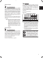
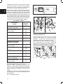
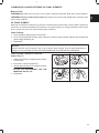
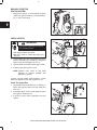
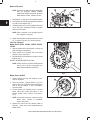
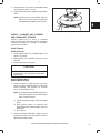
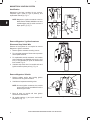
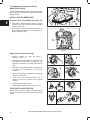
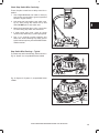
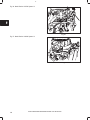
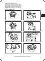
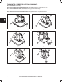
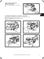
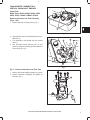
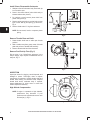
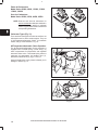
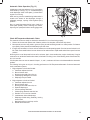
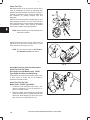
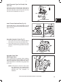
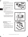
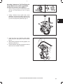
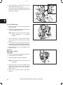
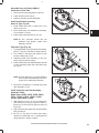
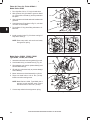
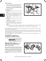
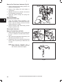
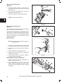
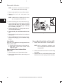
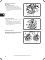
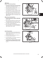
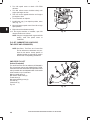
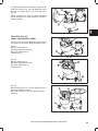
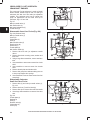
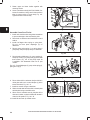
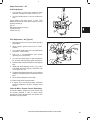
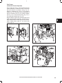
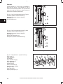
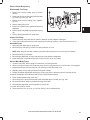
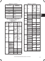
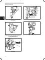
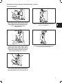
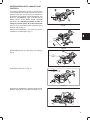
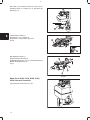
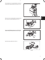
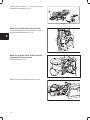
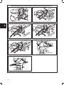
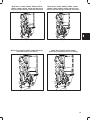
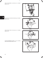
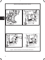
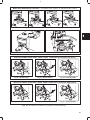
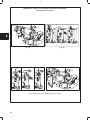
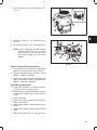
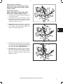
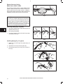
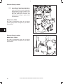
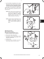
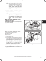
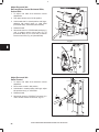
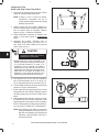
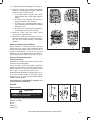
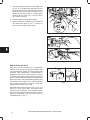
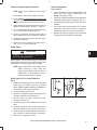
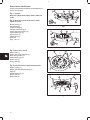
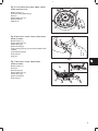
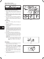
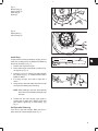
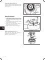
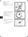
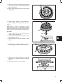
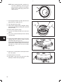
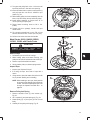
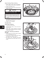
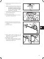
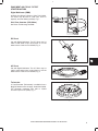
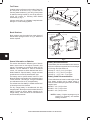
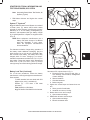
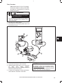
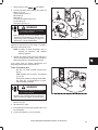
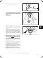
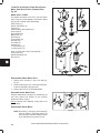
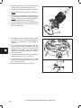
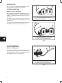
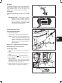
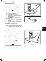
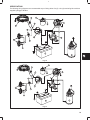
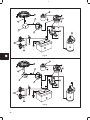
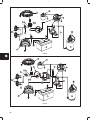
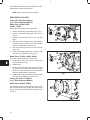
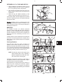
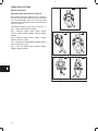
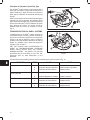
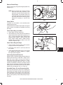
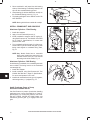
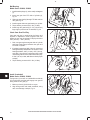
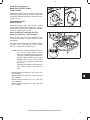
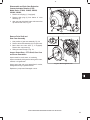
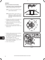
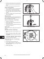
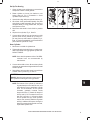
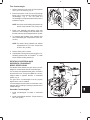
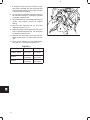
4
GOVERNOR BRACKETS, LINKAGES, AND
CONTROLS
The following drawings of governor controls (Figs.
14 through 49 and 61 through 136) are to show how
governor links and springs are to be installed on
carburetors. For governor control adjustments, see
Section 5, GOVERNORS. Figs. 14–22 below show
Models 60100, 61100, 80100, 81100 Horizontal
Crankshaft. “A” indicates movement of cable or
linkage to increase speed, “B” to decrease speed.
1
A
2
Fig. 14
Pull out rod (1) to increase speed. Governor spring
hooks in hole (2), Fig. 14.
Remote control assembly – turn screw (1) counterclockwise to increase speed, Fig. 15.
1
Fig. 15
Speed adjusting lever (1), with spring in #1 hole (2),
Fig. 16.
1
A
B
2
Fig. 16
Hook spring in this hole (1), Fig. 17.
A
B
1
Fig. 17
Place lever in choke detent. If choke is not fully closed,
bend link where shown (1) to attain full choke, Fig. 18.
1
Fig. 18
5