1
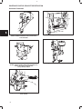
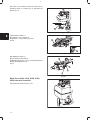
4 SECTION 4 Gov. Controls, Carb. Linkage & Flywheel Brakes Section Contents Page GOVERNOR CONTROL BRACKET IDENTIFICATION Horizontal Crankshaft . . . . . . . . . . . . . . . . . . . . . . . . . . . . . . . . . . . . . . . . . . . . . . . . . . . . . . . . . . . . . . . . . . . . . . . . . 2 Vertical Crankshaft . . . . . . . . . . . . . . . . . . . . . . . . . . . . . . . . . . . . . . . . . . . . . . . . . . . . . . . . . . . . . . . . . . . . . . . . . . . . 3 BAND BRAKE CONTROLS Disassemble . . . . . . . . . . . . . . . . . . . . . . . . . . . . . . . . . . . . . . . . . . . . . . . . . . . . . . . . . . . . . . . . . . . . . . . . . . . . . . . . . Remove Current and Early Style . . . . . . . . . . . . . . . . . . . . . . . . . . . . . . . . . . . . . . . . . . . . . . . . . . . . . . . . . . . . . . . . . . . . . . Assemble Current and Early Style . . . . . . . . . . . . . . . . . . . . . . . . . . . . . . . . . . . . . . . . . . . . . . . . . . . . . . . . . . . . . . . . . . . . . . Adjust . . . . . . . . . . . . . . . . . . . . . . . . . . . . . . . . . . . . . . . . . . . . . . . . . . . . . . . . . . . . . . . . . . . . . . . . . . . . . . . . . . . . . . . System 4 Electric Start Controls . . . . . . . . . . . . . . . . . . . . . . . . . . . . . . . . . . . . . . . . . . . . . . . . . . . . . . . . . . . . . . Test . . . . . . . . . . . . . . . . . . . . . . . . . . . . . . . . . . . . . . . . . . . . . . . . . . . . . . . . . . . . . . . . . . . . . . . . . . . . . . . . . . . . . . . . . 27 28 28 28 29 29 FLYWHEEL BRAKES Model Series 90000, 100000 . . . . . . . . . . . . . . . . . . . . . . . . . . . . . . . . . . . . . . . . . . . . . . . . . . . . . . . . . . . . . . . . . . . 30 Remove . . . . . . . . . . . . . . . . . . . . . . . . . . . . . . . . . . . . . . . . . . . . . . . . . . . . . . . . . . . . . . . . . . . . . . . . . . . . . . . . . . . 30 Assemble . . . . . . . . . . . . . . . . . . . . . . . . . . . . . . . . . . . . . . . . . . . . . . . . . . . . . . . . . . . . . . . . . . . . . . . . . . . . . . . . . 31 Brake . . . . . . . . . . . . . . . . . . . . . . . . . . . . . . . . . . . . . . . . . . . . . . . . . . . . . . . . . . . . . . . . . . . . . . . . . . . . . . . . . . 31 Inspect Switch . . . . . . . . . . . . . . . . . . . . . . . . . . . . . . . . . . . . . . . . . . . . . . . . . . . . . . . . . . . . . . . . . . . . . . . . . . . . . . . . . 31 Model Series 120000 . . . . . . . . . . . . . . . . . . . . . . . . . . . . . . . . . . . . . . . . . . . . . . . . . . . . . . . . . . . . . . . . . . . . . . . . . . 29 Remove . . . . . . . . . . . . . . . . . . . . . . . . . . . . . . . . . . . . . . . . . . . . . . . . . . . . . . . . . . . . . . . . . . . . . . . . . . . . . . . . . . . 31 Assemble . . . . . . . . . . . . . . . . . . . . . . . . . . . . . . . . . . . . . . . . . . . . . . . . . . . . . . . . . . . . . . . . . . . . . . . . . . . . . . . . . 30 Inspect Brake . . . . . . . . . . . . . . . . . . . . . . . . . . . . . . . . . . . . . . . . . . . . . . . . . . . . . . . . . . . . . . . . . . . . . . . . . . . . . . . . . . 31 Switch . . . . . . . . . . . . . . . . . . . . . . . . . . . . . . . . . . . . . . . . . . . . . . . . . . . . . . . . . . . . . . . . . . . . . . . . . . . . . . . . . 31 REMOTE CONTROLS . . . . . . . . . . . . . . . . . . . . . . . . . . . . . . . . . . . . . . . . . . . . . . . . . . . . . . . . . . . . . . . . . . . . . . . . . . . 4 Operation . . . . . . . . . . . . . . . . . . . . . . . . . . . . . . . . . . . . . . . . . . . . . . . . . . . . . . . . . . . . . . . . . . . . . . . . . . . . . . . . . . . . . 4 Remote Governor Control . . . . . . . . . . . . . . . . . . . . . . . . . . . . . . . . . . . . . . . . . . . . . . . . . . . . . . . . . . . . . . . . . . . . 4 Remote Throttle Control . . . . . . . . . . . . . . . . . . . . . . . . . . . . . . . . . . . . . . . . . . . . . . . . . . . . . . . . . . . . . . . . . . . . . . 4 Choke-A-Matic Control . . . . . . . . . . . . . . . . . . . . . . . . . . . . . . . . . . . . . . . . . . . . . . . . . . . . . . . . . . . . . . . . . . . . . 4 Adjustment All Model Series (except 120000) . . . . . . . . . . . . . . . . . . . . . . . . . . . . . . . . . . . . . . . . . . . . . . . . . . . . . . . . 4 Dial Control . . . . . . . . . . . . . . . . . . . . . . . . . . . . . . . . . . . . . . . . . . . . . . . . . . . . . . . . . . . . . . . . . . . . . . . . . . . 4 Model Series 120000 . . . . . . . . . . . . . . . . . . . . . . . . . . . . . . . . . . . . . . . . . . . . . . . . . . . . . . . . . . . . . . . . . . . 4 1 4 GOVERNOR CONTROL BRACKET IDENTIFICATION Horizontal Crankshaft Fig. 1 – 170400, 190400, 195400, 220400, 221400, 251400, 252400 with Swivel Control before Date Code 83121600 Fig. 4 – 253400, 255400 Fig. 2 – 170400, 171400, 190400, 194400, 195400, 221400, 222400, 252400, 254400 with Rack & Pinion Control after Date Code 83121500, except 253400, 255400 Fig. 5 – 230000, 240000, 300000, 320000 Fig. 3 – 176400, 192400, 226400, 250400, 256400 Lever Control 2 4 GOVERNOR CONTROL BRACKET IDENTIFICATION, (CONT’D) Vertical Crankshaft Fig. 6 – 194700, 195700, 196700, 254700, 257700, 258700, 259700, 28A700, 28B700, 28C700, 28D700, 28E700, 28M700, 282700, 283700, 285700, 286700, 288700, 289700 with Horizontal Rack & Pinion control for Briggs & Stratton/Walbro LMT Carburetors Fig. 7 – 170700, 190700, 191700, 192700, 193700, 194700, 195700, 196700, 220700, 252700, 253700, 254700, 257700, 256700, 258700, 280700, 28A700, 28B700, 28C700, 28D700, 28M700, 283700, 286700, 289700 with Vertical Rack & Pinion Control for Briggs & Stratton/Walbro LMT Carburetors Fig. 9 – Late Style, 170700, 171700, 190700, 191700, Swivel Control Bracket for Briggs & Stratton One Piece Flo-Jet Carburetors Fig. 10 – Early Style, 170700, 171700, 190700, 191700, Swivel Control Bracket for Briggs & Stratton One Piece Flo-Jet Carburetors Fig. 8 – 170000, 190000, 220000, 250000, 280000, except 286700, Vertical Rack & Pinion Control for Briggs & Stratton One Piece Flo-Jet Carburetors 3 4 REMOTE CONTROLS In general, there are three types of remote controls: remote governor control, remote throttle control, and Choke-A-Matic control. See the carburetor section and following pages for specific control assemblies and installation hook-up by engine model. REMOTE GOVERNOR CONTROL The remote governor control regulates the engine speed by changing the governor spring tension, thus allowing the governor to control the carburetor throttle at all times and maintain any desired speed. REMOTE THROTTLE CONTROL The remote throttle control is used on an engine having a fixed no load governed speed setting such as 3600 or 4000 RPM. This control enables an operator to control the speed of an engine, similar to an accelerator used on an automobile. However, when full governed speed is obtained, the governor prevents overspeeding and possible damage to the engine. At any point below the governed speed, the throttle is held in a fixed position and the engine speed will vary with the load. CHOKE-A-MATIC REMOTE CONTROL 1 On Choke-A-Matic carburetors, the remote control must be correctly adjusted in order to obtain proper operation of the choke and stop switch. See Carburetor section for details. Model Series 120000 1. Move control lever until a 1/8” (3.18 mm) dia. rod can be inserted through hole (1) in control plate and control lever, Fig. 11. Fig. 11 2. Place equipment control in “RUN” position and install casing and wire on control lever and control bracket, Fig. 11. A B Travel of remote control wire must be a minimum of 1–3/8” (35 mm) (B) in order to achieve full “CHOKE” (1) and “STOP” (2) position, Fig. 12. Distance (A) is 2–1/8” (54 mm). 2 1 CHOKE-A-MATIC DIAL CONTROL ADJUSTMENTS Fig. 12 Dial controls seldom require adjustment unless blower housing has been removed. 1 1. To Adjust: Place dial control knob in “START” position. 2 2. Loosen control wire screw (4) – move lever (2) to full choke position (1). Allow a 1/8” (3.18 mm) gap between lever and bracket as shown (3), Fig. 13. 3. While holding lever, tighten screw (4). Stop switch (5). 3 4 5 Fig. 13 4 4 GOVERNOR BRACKETS, LINKAGES, AND CONTROLS The following drawings of governor controls (Figs. 14 through 49 and 61 through 136) are to show how governor links and springs are to be installed on carburetors. For governor control adjustments, see Section 5, GOVERNORS. Figs. 14–22 below show Models 60100, 61100, 80100, 81100 Horizontal Crankshaft. “A” indicates movement of cable or linkage to increase speed, “B” to decrease speed. 1 A 2 Fig. 14 Pull out rod (1) to increase speed. Governor spring hooks in hole (2), Fig. 14. Remote control assembly – turn screw (1) counterclockwise to increase speed, Fig. 15. 1 Fig. 15 Speed adjusting lever (1), with spring in #1 hole (2), Fig. 16. 1 A B 2 Fig. 16 Hook spring in this hole (1), Fig. 17. A B 1 Fig. 17 Place lever in choke detent. If choke is not fully closed, bend link where shown (1) to attain full choke, Fig. 18. 1 Fig. 18 5 4 Bell crank (1) and remote control lever (2) move in directions shown to increase (A) or decrease (B) speed, Fig. 19. 1 A B 2 Fig. 19 Closed choke position (1) Stop switch in “run” position (2) Stop switch in “stop” position (3), inset Fig. 20 1 2 3 Fig. 20 Idle adjustment screw (1) Spring hooked in this hole (2) Speed adjusting screw – turn in to increase speed (3) Needle valve adjustment (4) Fig. 21 1 2 3 4 Fig. 21 Model Series 60200, 61200, 80200, 81200, 82200 Horizontal Crankshaft Typical remote control choke, Fig. 22. Fig. 22 6 4 Turn thumbscrew (1) counterclockwise as shown to increase speed, spring hooked in #4 hole (2), Fig. 23. 1 2 Fig. 23 Pull out rod (1) to increase speed (A), governor spring in this hole (2) in speed adjusting lever, Fig. 24. 1 2 A B Fig. 24 Turn in speed adjustment screw (2) to increase speed, needle valve (3), idle adjustment screw (1), Fig. 25. 1 2 3 Fig. 25 Inset shows spring attachments, Fig. 26. Fig. 26 7 4 Choke position closed (1), Inset shows spring attachment to stop switch, Fig. 27. 1 Fig. 27 Model Series 83400 Horizontal Crankshaft Turn speed adjusting screw (1) clockwise to increase, counterclockwise to decrease, Fig. 28. 1 Fig. 28 Model Series 80200, 82200, 90200 Horizontal Crankshaft, Air Vane Governor Standard controls, Fig. 29. Fig. 29 Manual choke, top mount remote control, Fig. 30. Fig. 30 8 4 Manual choke, manual friction throttle, Fig. 31. Fig. 31 Manual choke, remote control, governed idle. Fig. 32. Fig. 32 Choke-A-Matic, Fig. 33. Fig. 33 Manual choke, bottom mount remote control, Fig. 34. Fig. 34 9 4 Model Series 60300, 60400, 61300, 80300, 80400, 81400 Horizontal Crankshaft A 1 A A 1 Fig. 35 Fig. 36 Turn governor screw as shown to increase speed. Top speed limit device (1). A Fig. 37 Fig. 38 Turn governor screw as shown to increase speed. Move remote control lever as shown to increase speed. Swivel screw, (1). B A B A Fig. 39 Turn governor screw as shown to increase (A) or decrease (B) speed. 10 B Fig. 40 Move throttle cable as shown to increase (A) or decrease (B) speed. 4 Model Series 91200, 92200, 94200 Horizontal Crankshaft with date codes ending in A1 through A9 or E1 through E9 Fig. 41 Fig. 42 Fig. 43 Fig. 41 – Manual Friction Fig. 42 – Remote Control Fig. 44 Fig. 43 – Fixed Adjustable Model Series 93400 Horizontal Crankshaft A Fig. 45 Fig. 44 – Vehicle Control Model Series 133400 Horizontal Crankshaft A Fig. 46 Fig. 45 – Move lever (A) as indicated to increase speed. 11 4 Model Series 80000, 91200, 110000, 130000 Horizontal Crankshaft, Mechanical Governor Fig. 47 – Standard Controls Fig. 48 – Manual Choke, Manual Friction Fig. 49 – Choke-A-Maticr Fig. 50 – Manual Choke, Remote Controls A B Fig. 51 – Manual Choke, Remote Control, Governed Idle Fig. 53 – Vehicle Controls, Throttle Return 12 Fig. 52 – Fixed Adjustable 4 Model Series 100200, 130200 Horizontal Crankshaft Manual friction governor control. Pull knob up as indicated (A) to increase speed, Fig. 54. A Fig. 54 Remote control with governor, Fig. 55. Fig. 55 Standard governor control. Turn thumbscrew clockwise as indicated (A) to increase speed. Inset: remote control cable moves as indicated to increase speed (A) Fig. 56. A A Fig. 56 13 4 Choke-A-Matic remote control mounted on top of engine showing casing clamp (1), (inset A), and direction cable moves to close choke. Choke-A-Matic remote control (inset B) showing stop switch (2) direction to choke, (3), and movement of linkage to close choke, (4), Fig. 57. A 1 4 B 2 3 Fig. 57 Pull throttle control knob up to run (1), push down to stop (2), Fig. 58. 1 2 Fig. 58 Place lever (4) in choke detent (5). If choke (1) is not fully closed, adjust nylon nut (2) with socket wrench until choke just closes. Lever stop position (3), Fig. 59. 2 1 3 4 5 Fig. 59 Pull lever (1) to full choke position (2). The distance between throttle stamping and throttle screw stop (4) must be 9/16” (14.27 mm). To adjust, bend linkage where shown (3), Fig. 60. 1 2 4 3 Fig. 60 14 4 Model Series 176400, 19B400, 19E400, 19F400, 19G400, 192400, 196400, 197400 with Bell Crank Controls and One Spring, Horizontal Crankshaft Model Series 176400, 19B400, 19E400, 19F400, 19G400, 192400, 196400, 197400 with Bell Crank Controls and Two Springs, Horizontal Crankshaft Fig. 61 Fig. 62 Model Series 226400, 250400, 256400 Horizontal Crankshaft Control, One Spring Model Series 226400, 250400, 256400 Horizontal Crankshaft Control, Two Springs Fig. 63 Fig. 64 15 4 Adjust Choke-A-Matic as shown (A), to increase speed, Fig. 65. A Fig. 65 Adjust remote control cable as shown (A), to increase speed, Fig. 66. A Fig. 66 Adjust Manual Friction as shown (A), to increase speed, Fig. 67. A Fig. 67 Turn fixed adjustable as shown – (A) to increase speed, (B) to decrease speed, Fig. 68. B A Fig. 68 16 4 Model Series 170400, 190400, 195400, 220400, 221400, 251400, 252400 Horizontal Crankshaft with Swivel Lever Control before Date Code 83121600 Adjust Choke-A-Matic linkage and cable as shown (A), to increase speed, Fig. 69. A A Fig. 69 Adjust cable or turn knob as shown (A) to increase speed. Manual friction (1), fixed adjustable (2), remote control (3), Fig. 70. A A A 1 2 3 Fig. 70 Adjust as shown (A) to increase speed. Manual friction (1), fixed adjustable (2), remote control (3), Fig. 71. A A A 3 2 1 Fig. 71 Model Series 230000, 240000, 300000, 320000 Horizontal Crankshaft 1 1 Remote Governor Control Attach remote control casing and wire as shown in Figs. 72 or 73. Do not change the position of the small elastic stop nuts below the thumb nut (1). They ensure a governed idle speed and protection against overspeeding. Move lever as shown to increase (A) or decrease (B) speed. A Fig. 72 B Fig. 73 17 4 Thumb Nut Adjustment 1 Remove thumb nut and upper elastic stop nut (2), Figs. 76 and 77. Replace thumb nut and adjust to desired operating speed. (See Figs. 74-79). Do not change the position of the lower elastic stop nut. It provides protection against overspeeding. 1 Governed Idle All engines in Model Series 243400, 300400, 320400, and some 233400 engines use two governor springs (4), Fig. 78. The shorter spring keeps the engine on governor, even at idle speed. If moderate loads are applied at idle, the engine will not stall. A B Fig. 74 Fig. 75 A 2 2 3 2 B A 4 Fig. 76 Fig. 77 Fig. 78 A A Fig. 79 18 4 Model Series 220000, 250000 Horizontal Crankshaft with Rack & Pinion Control after Date code 83121500, Except 253400, 255400 1 B A A Fig. 80 Fig. 81 Fig. 80 – Choke-A-Matic Fig. 81 – Remote Control Choke (1) B A A Fig. 82 Fig. 83 Fig. 82 – Manual Friction Fig. 83 – Fixed Adjustable Figs. 80 – 83: Move as shown (A) to increase speed, (B) to decrease speed. 19 4 Model Series 253400, 255400 Horizontal Crankshaft A A Fig. 84 Fig. 85 1 A Fig. 86 Fig. 87 – Fixed speed screw (1) Figs. 84 – 87: Move as shown (A) to increase speed, (B) to decrease speed. 20 4 Model Series 90000 Vertical Crankshaft – “A” indicates “FAST” position, “B” indicates “STOP” position A B B A Fig. 88 Fig. 89 Fig. 90 Fig. 91 Model Series 9B900, 9C900, 98900, 10A900, 10B900, 10C900 Vertical Crankshaft, Dual Spring 1 2 1 1 2 Fig. 92 – Manual Friction Fig. 93 – Remote Control Fig. 94 – Fixed Adjustable Model Series 9B900, 9C900, 98900, 10A900, 10B900, 10C900 Vertical Crankshaft, Single Spring 1 2 1 1 2 Fig. 95 – Manual Friction Fig. 96 – Remote Control Fig. 97 – Fixed Adjustable Figs. 92 – 97: Governor control lever (1), governor control bracket (2). 21 4 Model Series 120000 Vertical Crankshaft A Fig. 98 “A” indicates increase speed, “B” indicates decrease speed. Model Series 90700, 110700, 112700 Vertical Crankshaft Model Series 91700, 111700, 114700 Vertical Crankshaft B A B Fig. 99 22 Fig. 100 A 4 Model Series 130700, 131700, 132700 Vertical Crankshaft – “A” shows speed increase, “B” shows decrease. B B A A Fig. 101 Fig. 102 Model Series 100900, 130900 Vertical Crankshaft 2 1 Throttle lever (1) Choke lever (2) Choke and throttle remote control casings (3) Casing screws (4) Fig. 103 3 4 Fig. 103 Choke closed (1) Lever in choke (2) Lever in stop(3) Stop switch (4) Blade (5) Fig. 104 1 4 5 3 2 Fig. 104 Place control in choke detent (1). If choke does not fully close, bend linkage as shown until choke is closed (2), Fig. 105. 2 1 Fig. 105 23 4 Model Series 170700, 190700, 191700, 192700, 193700, 220700, 252700, 253700, 280000 Vertical Crankshaft with Rack & Pinion Control Except Model 286700 Move as shown (A) to increase speed, Fig. 107. A Fig. 106 24 Fig. 107 4 Model Series 194700, 195700, 254700, 257700, 283700, 286700 Vertical Crankshaft With Horizontal Control Rack & Pinion Control A 1 A Fig. 108 Move as shown (A) to increase speed. Slide control (1), Fig. 109. Fig. 109 Model Series 194700, 195700, 196700, 254700, 257700, 283700, 286700 Vertical Crankshaft With Vertical Rack & Pinion Control A A A Move as shown (A) to increase speed, Figs. 110-111. Fig. 110 Fig. 111 25 4 Model Series 170700, 171700, 190700, 191700 Vertical Crankshaft with Swivel Lever Control A A A Fig. 112 Fig. 113 A A Fig. 114 A Fig. 115 Move as shown (A) to increase speed, Figs. 112-115. 26 4 BAND BRAKE CONTROLS Model Series 92000, 93000, 94000, 95000, 110000 System 3 and 4 engines are equipped with the band brake feature, Fig. 116. The band brake MUST STOP the engine (cutter blade) within three seconds after operator releases equipment safety control, Fig. 117. If stopping time exceeds three seconds with equipment speed control set in “FAST” position, remove blower housing (3), and brake cover (2), and examine following for adjustment, alignment, or damage: a. Band brake worn or damaged. b. Anchor post (5) or alternate type – inset (4) misaligned or bent. c. Brake spring not securely anchored or loose. d. Control bracket lever (1) rivet worn or loose. (Check ignition system as noted in Section 2.) e. Control bracket (1) misadjusted. f. Equipment controls (1) damaged, Fig. 117. 3 4 2 5 1 Fig. 116 1 To examine, adjust, or replace band brake, disconnect spark plug wire and place in holding tab. For System 4 engines, disconnect battery wires at connector, loosen battery holder screws and remove battery. Fig. 117 DISASSEMBLY TO REMOVE BAND BRAKE 1. Remove brake control bracket cover. 2. Loosen cable clamp screw and remove cable from control lever, Fig. 116. NOTE: Contact equipment manufacturer for control cable specifications or replacement. 3. Remove two switch cover screws. On System 4 engines, move cover (1) as shown in Fig. 118. Handle with care to prevent damage to lever caused by link when moving switch cover. 1 Fig. 118 27 4 REMOVE BAND BRAKE 1. Remove blower housing and rotating screen, Fig. 116. 3 2. On current style band brake brackets, release brake spring (1) and lift band brake (2) up off both stationary and moving posts (3), Fig. 119. .030”(.76 mm) 3. On early style brake brackets, use tang bender tool #19229 (1) to bend control lever tang (2) to clear band brake loop, then release brake spring tension and remove band brake (4), Fig. 120. 4. Replace band brake if brake material is damaged or worn to less than .030” (.76 mm) thick, (inset, Fig. 119). 2 1 5. Remove two screws. Remove control bracket from cylinder. NOTE: Disconnect control lever from starter link (System 4 engines only) using care to prevent switch cover lever damage. Fig. 119 1 2 6. Remove stop switch wire from stop switch terminal. ASSEMBLE CONTROL BRACKET AND BAND BRAKE 1. Reinstall stop switch wire on control bracket. 2. Assemble control bracket to cylinder with screws finger tight. 4 3 3. On new style brackets, place band brake on stationary post and hook over end of movable post until band bottoms, Fig. 119. Fig. 120 4. On old style brackets, install brake on stationary and movable posts, then use tool #19229 (2) to bend retainer tang over band brake loop, Fig. 121. 2 NOTE: Brake material on steel band MUST be on flywheel side after assembly. Adjusting Band Brake 1. Place bayonet end of Band Brake Adjusting Gauge, Tool #19256 (1), in control lever, Fig. 121. 2. Rotate control lever far enough to install other end of gauge in cable clamp screw hole. 3. Install brake spring. NOTE: For ease of assembly, brake spring must be temporarily removed from control bracket spring anchor. 4. Re-attach brake spring to control bracket spring anchor IMMEDIATELY after installing control bracket screws finger tight. 28 1 Fig. 121 4 5. With brake spring installed, apply pressure to the control bracket ONLY. Move it until gauge link tension is JUST eliminated. 6. Hold control bracket in this position while torquing screws to 30 in. lbs. (3 Nm). 7. Remove gauge. NOTE: Some manufacturers install a cable clamp bracket using a pop rivet in the control bracket cable clamp screw hole. Place bayonet end of gauge in control lever and rotate control lever sufficiently to install other end of gauge into pop rivet hole. Adjust as noted above. TEST BAND BRAKE 1. To test band brake adjustment, use Torque Wrench, Tool #19197, Starter Clutch Wrench, Tool #19244, and/or a 7/8” socket. 2. With band brake engaged, rotate flywheel clockwise, Fig. 122, and note torque wrench reading. 3. If less than 45 in. lbs. (5 Nm) of torque is required to rotate flywheel, check the following for damage, misalignment, or misadjustment: a. Band Brake Lining; b. Band Brake Anchors; c. Control Bracket; d. Brake Spring; e. Brake Spring Anchor. Correct, readjust and repeat band brake test. Fig. 122 When band brake is released, engine must turn freely. If band brake drags against flywheel, restricting movement, check for damaged band brake or anchors. FINAL ASSEMBLY 3 Install rotating screen (3) and blower housing (2) on engine. Tighten screws. Note location of blower housing guard (1), Fig. 123. INSTALL ELECTRIC STARTER CONTROLS (System 4) 1. Install starter link into control lever. 2 2. Insert other end of link in switch cover lever. 3. Rotate switch cover into position on starter motor. 4. Fasten screws securely. 1 NOTE: If equipped with key switch, ignition link may be omitted. Fig. 123 5. Install equipment safety control cable to control lever. 29 4 6. Tighten cable clamp screw securely. 7. Conduct Stop Switch and Stop Switch Wire Tests described in Section 2, Ignition. 8. Install brake control bracket cover and tighten screws. 9. Place battery in holder and tighten screws. 10. After engine is installed on equipment, connect battery wires to connector and place wire on spark plug. 11. Re-test stopping time. FLYWHEEL BRAKE MODEL SERIES 90000, 10A900, 10B900, 10C900, 120000 1 Description The flywheel brake is part of the safety control required for some applications of this engine models. The flywheel brake MUST stop the engine within three seconds, while running at FAST speed position, when the operator releases the equipment safety control. Remove Flywheel Brake All except Model Series 120000 1. Remove screw from brake cover (1) and lift brake cover straight up, Fig. 124. 2. Remove three (3) blower housing screws and remove blower housing. Fig. 124 1 2 3. Straighten stop switch wire (2) and remove from stop switch (1). Remove brake spring (3), Fig. 125. 4. Remove two screws from brake bracket and remove bracket. 3 Fig. 125 MODEL SERIES 120000 1 1. Remove finger guard (1) and fuel tank (2), Fig. 126. 2. Remove dipstick and oil fill tube (1), Fig. 127. 2 Fig. 126 30 4 3. Remove blower housing and rewind starter (3, 2), Fig. 127. 3 2 1 Fig. 127 4. Disconnect spring (2) from brake anchor (3), Fig. 128. 1 2 5. Disconnect stop switch wire (1) from stop switch. NOTE: If engine is equipped with electric starter, disconnect both wires (4) from starter interlock switch (5). Remove two screws from brake bracket (6) and remove bracket. 3 7 6 5 4 Fig. 128 Inspect Flywheel Brake and Switches 1. Inspect brake lining on brake lever. Replace brake assemble if lining is less than .090” (2.29 mm). 2. Test stop switch as described in Section 2, STOP SWITCH – REMOTE CONTROL. 3. Model Series 120000, test electric starter interlock switch as described in Section 7B, INTERLOCK SWITCH – ELECTRIC STARTER. Assemble Flywheel Brake 1. Install brake assembly on cylinder and torque mounting screws to 40 in. lbs. (5 Nm). 2. Install stop switch wire and bend end of wire 90°. Install interlock switch wires on interlock switch, if used. 3. Install brake spring. 4. Install blower housing as described in Section 7A, SERVICE STARTER. 5. Model Series 120000, install dipstick tube and dipstick. 6. Model Series 120000, install fuel tank and finger guard. 7. ANSI requires blade to stop at 3 seconds or less. 31 5 SECTION 5 Governors Section Contents SAFETY Page Governed Speed Limits, All Model Series . . . . . . . . . . . . . . . . . . . . . . . . . . . . . . . . . . . . . . . . . . . . . . . . . . . . . . . . 3 MECHANICAL GOVERNORS HORIZONTAL CRANKSHAFT Disassemble Model Series 60000, 80000, with governor lever and shaft mounted on crankcase cover . . . . . . . . . . . . . . . 8 Model Series 80000, 83400, 93400, 100200, 130000, 170000, 190000, 220000, 250000, with governor crank in cylinder . . . . . . . . . . . . . . . . . . . . . . . . . . . . . . . . . . . . . . . . . . . . . . . . . . . . . . . . . . . . . . . . . . . . . 7 Model Series 230000, 240000, 300000, 320000 . . . . . . . . . . . . . . . . . . . . . . . . . . . . . . . . . . . . . . . . . . . . . . . . . 18 Assemble Model Series 60000, 80000 with governor lever and shaft mounted on crankcase cover . . . . . . . . . . . . . . . 9 Model Series 80000, 83400, 93400, 100200, 130000, 170000, 190000, 220000, 250000, with governor crank mounted in cylinder . . . . . . . . . . . . . . . . . . . . . . . . . . . . . . . . . . . . . . . . . . . . . . . . . . . . . . . . . . . . . 8 Model Series 230000, 240000, 300000, 320000 . . . . . . . . . . . . . . . . . . . . . . . . . . . . . . . . . . . . . . . . . . . . . . . . . 18 Adjust Governor, Static . . . . . . . . . . . . . . . . . . . . . . . . . . . . . . . . . . . . . . . . . . . . . . . . . . . . . . . . . . . . . . . . . . . . . . . . 11 Adjust Governor Dynamic Top No Load RPM, EXCEPT GENERATORS Model Series 60000, 80000 with governor lever and shaft mounted on crankcase cover . . . . . . 9 Model Series 100200, 130000, 170000, 190000, 220000, 250000 (except 253400, 255400) . . 14 Model Series 176400, 19A400, 19B400, 19C400, 19E400, 19F400, 19G400, 196400, 197400, 226400, 250400, 256400, Two Spring System . . . . . . . . . . . . . . . . . . . . . . . . . . . . . . . . . . 14 Model Series 253400, 255400 . . . . . . . . . . . . . . . . . . . . . . . . . . . . . . . . . . . . . . . . . . . . . . . . . . . . . . . . 16 Model Series 233400, 243400, 300000, 320000 . . . . . . . . . . . . . . . . . . . . . . . . . . . . . . . . . . . . . . . . 18 Top No Load RPM, GENERATORS Model Series 83400 . . . . . . . . . . . . . . . . . . . . . . . . . . . . . . . . . . . . . . . . . . . . . . . . . . . . . . . . . . . . . . . . . 11 Model Series 80000, 112200, 130000 (except 133400), 170000, 190000, 220000, 250000 (except 253400, 255400) . . . . . . . . . . . . . . . . . . . . . . . . . . . . . . . . . . . . . . . . . . . . . . . . . . . . . . . . . . . . 17 Model Series 93400, 133400, 176400, 196400, 226400, 256400 . . . . . . . . . . . . . . . . . . . . . . . . . . 11 Governed Idle Model Series 170000, 190000, 220000, 250000, Rack and Pinion Control . . . . . . . . . . . . . . . . . . 14 Model Series 170000, 190000, 220000, 250000, Swivel Control . . . . . . . . . . . . . . . . . . . . . . . . . . 14 Model Series 133400, 176400, 196400, 226400, 256400 . . . . . . . . . . . . . . . . . . . . . . . . . . . . . . . . 13 Model Series 253400, 255400 . . . . . . . . . . . . . . . . . . . . . . . . . . . . . . . . . . . . . . . . . . . . . . . . . . . . . . . . 17 Model Series 233400, 234300, 300000, 320000 . . . . . . . . . . . . . . . . . . . . . . . . . . . . . . . . . . . . . . . . 19 Model Series 93400, 133400, 176400, 196400, 226400, 256400 . . . . . . . . . . . . . . . . . . . . . . . . . . 10 Model Series 130200, 170000, 190000, 220000, 250000, 280000 (except 253400, 255400) . . 14 Model Series 230000, 240000, 300000, 320000 . . . . . . . . . . . . . . . . . . . . . . . . . . . . . . . . . . . . . . . . 18 Manual Friction Model Series 93400, 133400, 176400, 196400, 226400, 256400 . . . . . . . . . . . . . . . . . . . . . . . . . . 16 Remote Control Model Series 93400, 133400, 176400, 196400, 226400, 256400 . . . . . . . . . . . . . . . . . . . . . . . . . . 16 NOTE: SPECIFICATION TABLES BEGIN ON PAGE 28 OF THIS SECTION. 1 5 Section Contents, Cont’d. HORIZONTAL CRANKSHAFT, (Cont’d) Page Model Series 80000, 83400, 93400, 100200, 130000, 170000, 190000, 220000, 250000, with governor crank mounted in cylinder . . . . . . . . . . . . . . . . . . . . . . . . . . . . . . . . . . . . . . . . . . . . . . . 11 Governor Shaft Bushing, Replace Model Series 80000, 83400, 100200, 100900, 130000, 170000, 190000, 220000, 250000 . . . . . . . . . 21 Model Series 230000, 240000, 300000, 320000 . . . . . . . . . . . . . . . . . . . . . . . . . . . . . . . . . . . . . . . . . . . . . . 18 Governor Spring Hole Location Model Series 93400, 133400, 176400, 196400, 226400, 250400, 256400 . . . . . . . . . . . . . . . . . . . . . 10-11 Governor Spring Hole Location – Generators only . . . . . . . . . . . . . . . . . . . . . . . . . . . . . . . . . . . . . . . . . . . . 11 PNEUMATIC GOVERNORS Adjust Governed Idle Model Series 80000, 90000 Horizontal Crankshaft with Control Panel . . . . . . . . . . . . . . . . . . . . . . . . . . . . Top No Load RPM Model Series 9B900, 9C900, 93900, 95900, 96900, 98900, 10A900, 10B900, 10C900 Single & Dual Spring . . . . . . . . . . . . . . . . . . . . . . . . . . . . . . . . . . . . . . . . . . . . . . . . . . . . . . . . . . . . . . . . . . . . . . . . . . . . . . . . . . . . Model Series 80000, 90200, 91200, 94200 Horizontal Crankshaft with Control Panel . . . . . . . . . . . . . . . Governor Spring Remove, Model Series 90000, 110000, Vertical Crankshaft . . . . . . . . . . . . . . . . . . . . . . . . . . . . . . . . . . . . . . . . Install, Model Series 90000, 110000, Vertical Crankshaft . . . . . . . . . . . . . . . . . . . . . . . . . . . . . . . . . . . . . . . . . . 4 5 5 6 6 MECHANICAL GOVERNORS VERTICAL CRANKSHAFT Disassemble Model Series 91700, 94500, 94900, 95500, 111700, 113900, 114700, 114900 (Current & Early Style) . . Model Series 120000 . . . . . . . . . . . . . . . . . . . . . . . . . . . . . . . . . . . . . . . . . . . . . . . . . . . . . . . . . . . . . . . . . . . . . . . . Assemble Model Series 91700, 94500, 94900, 95500, 111700, 113900, 114700, 114900 (Current & Early Style) . . Model Series 120000 . . . . . . . . . . . . . . . . . . . . . . . . . . . . . . . . . . . . . . . . . . . . . . . . . . . . . . . . . . . . . . . . . . . . . . . . Model Series 170000, 190000, 220000, 250000, 280000 . . . . . . . . . . . . . . . . . . . . . . . . . . . . . . . . . . . . . . . . . Adjust Governor – Static Except Model Series 91700, 94500, 94900, 95500, 111700, 113900, 114700, 114900, (Early) . . . . . . Model Series 91700, 94500, 94900, 95500, 111700, 113900, 114700, 114900, (Current Style) . . . . . . Adjust Governor Dynamic Top No Load RPM Model Series 120000, Three-In-One . . . . . . . . . . . . . . . . . . . . . . . . . . . . . . . . . . . . . . . . . . . . . . . . . . . . . Model Series 120000, Early Style . . . . . . . . . . . . . . . . . . . . . . . . . . . . . . . . . . . . . . . . . . . . . . . . . . . . . . . . Model Series 170000, 190000, 220000, 250000, 280000 . . . . . . . . . . . . . . . . . . . . . . . . . . . . . . . . . . . Model Series 91700, 94500, 94900, 95500, 111700, 113900, 114700, 114900 (Current & Early Style) . . Model Series 120000 . . . . . . . . . . . . . . . . . . . . . . . . . . . . . . . . . . . . . . . . . . . . . . . . . . . . . . . . . . . . . . . . . . . Model Series 170000, 190000, 220000, 250000, 280000 . . . . . . . . . . . . . . . . . . . . . . . . . . . . . . . . . . . Governed Idle Rack and Pinion Control, Horizontal & Vertical Slide . . . . . . . . . . . . . . . . . . . . . . . . . . . . . . . . . . . . . . . . Swivel Control . . . . . . . . . . . . . . . . . . . . . . . . . . . . . . . . . . . . . . . . . . . . . . . . . . . . . . . . . . . . . . . . . . . . . . . . . Governor Spring, Install Model Series 91700, 94500, 94900, 95500, 111700, 113900, 114700, 114900 (Current & Early Style) . . Governor Shaft Bushing, Replace Model Series 91700, 94500, 94900, 95500, 111700, 113900, 114700, 114900, (Current & Early Style) . . . NOTE: SPECIFICATION TABLES BEGIN ON PAGE 28 OF THIS SECTION. 2 22 21 21 22 20 20 20 24 24 25 24 11 11 26 26 23 22 5 TOP NO LOAD GOVERNED SPEED LIMITS To comply with specified top governed speed limits, Briggs & Stratton supplies manufacturers with engines using either calibrated governor springs or an adjustable top no load speed. Both methods will regulate top governed speed when the engine is operated on a rigid test stand. However, the design of the cutter blade, deck, etc., can affect engine speeds. Therefore, the top no load speed should be checked with a tachometer when the engine is operated on a completely assembled machine. Lawn mowers should be operated on a hard surface to eliminate cutting load on the blade. If a governor spring must be replaced, search the appropriate Illustrated Parts List by engine type number. NOTE: Worn linkage or damaged governor springs should be replaced to ensure proper governor operation. CAUTION: After a new governor spring is installed, check engine top no load speed. Run engine at half throttle to allow the engine to reach normal operating temperature before measuring speed with a tachometer. Table No. 1, Page 28, lists various lengths of rotary lawn mower cutter blades, and the maximum blade rotational speeds, which will produce blade tip speeds of 19,000 feet per minute. If a service replacement engine is used, check the top no load speed with the engine operating on a completely assembled mower. If necessary, change the governor spring or adjust the top no load speed limit device, so the engine will not exceed the recommended speed. See page 6 for adjustment procedure for mechanical governor. See TABLE NO. 1, page 28 for RPM and blade length. NOTE: For correct no load RPM by model and type, see Engine Sales Manual, MS-4052 or MS-6225, Service Engine Sales Manual microfiche under note column, or MAXIMUM RPM TABLE at end of each manual for the model engine. NOTE: SPECIFICATION TABLES BEGIN ON PAGE 28 OF THIS SECTION. 3 5 PNEUMATIC GOVERNOR SYSTEMS (FIGS. 1, 2) 1 Adjust Top No Load Speed, Model Series 80000, 90000 Pneumatic Governor with Control Panel 1. Run engine until it reaches operating temperature or for about 5 minutes. 2. Set control lever or remote controls to fast position with engine running. 3. Adjust governed idle by turning stop nut (3) and idle speed screw (2), Fig. 2. Turn stop nut clockwise (A) to increase speed, counterclockwise (B) to decrease. Fig. 1 2 4. Use tool #19229 (4), to bend spring anchor tang (1, Fig. 1), to obtain the proper top no load RPM, Figs. 3 and 4. Fixed speed tang (5), Figs. 3 and 4. Adjust Governed Idle Some engines are equipped with governed idle. Governed idle permits the governor to operate at idle speeds while the engine is operating under light loads. B A Fig. 2 1. Place control lever in minimum speed position with engine running at operating condition. 4 2. 80000 Series: Hold throttle lever against stop and adjust idle speed screw (2), to obtain 1600 RPM. Release throttle lever. Then, turn governed idle stop nut (3) to obtain 1750 RPM, Fig. 2. 3. 90000 Series, Low Emissions Carburetors, Type Numbers ending in A1-A9 or E1-E9 NOTE: Fixed adjustable control: before control lever can be moved to slow position, fixed speed tang (5), Figs. 3, 4, must be bent down to move lever. 5 Fig. 3 NOTE: Fixed adjustable control: After setting governed idle, move control lever back to fast speed position and bend fast speed tang up to hold speed control lever. 5 Fig. 4 NOTE: SPECIFICATION TABLES BEGIN ON PAGE 28 OF THIS SECTION. 4 3 5 Adjust Top No Load Speed Pneumatic Governor, Dual Spring Control Model Series 9B900, 9C900, 98900, 10A900, 10B900, 10C900. 2 3 Single Spring Control Model Series 9B900, 9C900, 93900, 95900, 96900, 98900, 10A900, 10B900, 10C900 1. Run engine until it reaches operating temperature or for about 5 minutes. 2. Move governor lever (1) to “Fast Position.” Hole in lever (2) will line up with hole in governor control bracket (4). Insert 1/8” rod (3) through both holes to lock lever position, Figs. 5, 6. 1 4 Fig. 5 3. Dual Spring: Using Tool #19229 or 19352, Tang Bender (5), bend secondary governor spring tang, (“A” to increase, “B” to decrease), until there is no tension on secondary spring, Fig. 6. B A 5 1 4 Fig. 6 4. Bend primary governor spring tang, (“A” to increase, “B” to decrease), until engine speed is 200 RPM less than “TOP NO LOAD” RPM, Dual Spring, or at “TOP NO LOAD” RPM, Single Spring, Fig. 7. 5 B A 5. Dual Spring: Bend secondary governor spring tang until “TOP NO LOAD” RPM is obtained, Fig. 6, as specified in Engine Sales Manual, MS-4052 or MS-6225, Service Engine Sales Manual microfiche. 1 4 Fig. 7 NOTE: SPECIFICATION TABLES BEGIN ON PAGE 28 OF THIS SECTION. 5 5 Replace Governor Spring Model Series 90000, 110000 1 2 The governor springs used on engine Model Series 90000, 110000 are made with double end loops for a secure attachment and proper governor regulation. Springs with double end loops are easily removed and installed by following the procedure shown below. Fig. 8 CAUTION: DO NOT use a needle-nosed pliers or the end loops of the governor spring will be deformed. When the governor spring is correctly installed, the spring will be positioned as shown in Fig. 8, with loop (1) horizontal, end of spring pointing down, and loop (2) vertical, end of spring pointing toward engine. Removing Spring (Fig. 9, typical) 1. Twist spring toward engine until end of loop can be pushed under lever (A). 2. Push spring forward (B). 3. Twist spring toward engine until end of loop snaps out of hole in lever (C). A B Fig. 9 Installing Spring (Fig. 10, typical) 1. Steady link (1) with finger and grasp spring as shown, (A) 2. Assemble end of loop into link eyelet, (B). 3. Twist spring toward you to fully link as shown in inset, (C). 1 A B C Fig. 10 NOTE: SPECIFICATION TABLES BEGIN ON PAGE 28 OF THIS SECTION. 6 C 5 MECHANICAL GOVERNOR SYSTEM HORIZONTAL CRANKSHAFT (Fig. 11, typical) A 1 1 1. Fig. “A” shows engine not running, throttle open (1), spring compressed (2), and counterweights closed (3). Turning thumbscrew as shown (A) increases speed. 2. Fig. “B” shows engine running, throttle closing (1), spring stretching (2), and counterweights opening (3). 2 3 2 3 A B Fig. 11 Mechanical Governors Horizontal Crankshaft Model Series 80000, 83400, 100200, 130000, 170000, 190000, 220000, 251400, 252400, 254400 With Governor Crank in Cylinder Typical governor components on horizontal shaft models are illustrated in Fig. 12. Carburetor (1) Throttle link (2) Manual governor control (3) Governor link (4) Cam gear (5) Governor gear (6) Governor lever (7) Governor spring (8) 2 3 4 5 1 6 7 8 Fig. 12 The only disassembly necessary is removing the governor assembly as one unit from the governor gear shaft on the crankcase cover on horizontal models, Fig. 13. Governor crank should point down (1), as shown. 2 1 Fig. 13 NOTE: SPECIFICATION TABLES BEGIN ON PAGE 28 OF THIS SECTION. 7 5 Assemble Horizontal Crankshaft 3 On horizontal crankshaft models, the governor rides on a short stationary shaft and is retained by the governor shaft, with which it comes in contact after the crankcase cover is secured in place. 1 2 1. Press governor cup (2), Fig. 13, against crankcase cover to seat retaining ring on shaft, prior to installing crankcase cover. 4 5 6 NOTE: It is suggested that the assembly of the crankcase cover be made with the crankshaft in a horizontal position. Fig. 14 2. The governor crank should hang straight down parallel to the cylinder axis (1), Fig. 13. NOTE: If the governor crank is clamped in an angular position, pointing toward the crankcase cover, it is possible for it to be jammed inside of the governor assembly, resulting in damage when the engine is started. 3. After the crankcase cover and gasket are in place, install cover screws. Be sure that screw in hole (1) Fig. 14, has nonhardening sealant, such as Permatex II, on threads of screw. 4. Complete installation of remaining governor linkages and carburetor and then adjust governor shaft and lever. See “Adjust Governor, Static”, page 11. NOTE: See page 21, 3/16” (4.7 mm) inside diameter, or page 18, 1/4” (6 mm) inside diameter, for procedure if necessary to replace governor crank bushing. MECHANICAL GOVERNORS Model Series 60000, 80000 With Governor Lever and Shaft Mounted on Crankcase Cover Disassemble 1. To service governor, remove crankcase cover. 2. Loosen the screw on the governor lever (1) and pull lever from governor shaft (2). 3. Loosen the two mounting screws to remove gear housing (8). As the housing is removed, the governor gear (6) will slip off the housing shaft. Note the steel thrust washer (7) between the gear and the governor housing. 5 3 8 2 4. Remove roll pin (3) and washer from governor shaft. 5. Unscrew shaft from follower (4) by turning clockwise to remove. NOTE: SPECIFICATION TABLES BEGIN ON PAGE 28 OF THIS SECTION. 8 7 6 4 1 Fig. 15 5 Assemble 4 8 1. Push governor shaft (2) into crankcase cover, with threaded end in. 2 2. Assemble small washer on the inner end of the shaft, then screw shaft into governor follower (4) by turning shaft counterclockwise. 3. Tighten securely. Turn shaft until follower (4) points down as illustrated, Fig. 16. 9 1 4. Place washer on outside end of shaft. 5. Install roll pin (3). The leading end of the pin should just go through the shaft so pin protrudes from only one side of shaft. Fig. 16 6. Place thrust washer and then governor gear on shaft in gear housing. 7. Hold governor housing in a vertical (normal) position (8) and assemble housing with gear in position so point of steel cup on gear (9) rests against crank follower. 8. Tighten housing with two mounting screws. 9. Assemble governor lever to lever shaft with lever pointing downward at about a 30° angle. Final adjustment will be made later when carburetor linkage is assembled. Adjust Top No Load Speed A 1. Start and run engine at half throttle for five minutes to bring engine to operating temperature. 1 2. Move speed control lever to maximum RPM position. 3. Turn knob (1) to increase (A) or decrease RPM to desired speed, Fig. 17. 2 3 4 5 Fig. 17 NOTE: SPECIFICATION TABLES BEGIN ON PAGE 28 OF THIS SECTION. 9 5 Governor Spring Location Note: Consult Engine Sales Manual, MS-4052 or Service Engine Sales Manual Microfiche at the end of each manual to determine specified RPM for engine, EXCEPT FOR GENERATOR ENGINES. See text for Top No Load Speed and Governed Idle adjustments according to engine model and application. Model Series 93400 See Table 4, Specifications, Page 28, and place governor spring in holes 1 through 6, Fig. 18, to attain required RPM. Fig. 18 Governor Spring Location Model Series 133400 See Table 5, Specifications, Page 28, and place governor spring in holes 1 through 8, Fig. 19, to attain required RPM. Fig. 19 NOTE: SPECIFICATION TABLES BEGIN ON PAGE 28 OF THIS SECTION. 10 5 Single & Dual Spring Model Series 176400, 19B400, 19C400, 19E400, 19F400, 19G400, 192400, 196400, 226400, 250400, 256400 See Table No. 6, Specifications, Page 28, and place governor spring in holes 1 through 12, Fig. 20, to attain required RPM. Generator Engines Model Series 93400 Place governor spring in governor lever hole number 2 for 50 Cycle (3000 RPM) or hole number 3 for 60 Cycle (3600 RPM) generators. DO NOT USE HOLE LOCATIONS SHOWN IN TABLE NO 4, SPECIFICATIONS, Page 28. Generator Engines Model Series 133400 Place governor spring in governor lever hole number 2 for 50 Cycle (3000 RPM) or hole number 4 for 60 Cycle (3600 RPM) generators. DO NOT USE HOLE LOCATIONS SHOWN IN TABLE NO. 5, SPECIFICATIONS, page 28. Fig. 20 Generator Engines Model Series 176400, 19B400, 19C400, 19E400, 19F400, 19G400, 196400, 226400, 250400, 256400 Place governor spring in governor lever hole number 4 for 50 Cycle (3000 RPM) or hole number 8 for 60 Cycle (3600 RPM) generators. DO NOT USE HOLE LOCATIONS SHOWN IN TABLE NO. 6, SPECIFICATIONS, page 28. Static Governor Adjustment Horizontal Crankshaft 1. Loosen screw holding governor lever to governor crank. 2. Rotate throttle plate linkage from idle position to wide open position. Note direction of rotation of the governor arm attached to the throttle linkage. 3. Place and hold the linkage in high speed position. 4. While holding the linkage in this position, use an appropriate tool to rotate the governor shaft until it stops in the direction noted in step 2. 5. Tighten screw holding governor lever to governor crank. Torque to 35 – 45 in. lbs. (3 – 5 Nm). 6. Before starting engine, manually actuate governor linkage to check for binding. A B Final Governor Adjustment Adjust Top No Load Speed Model Series 83400 (Generator) Turn screw to 3750 RPM, Fig. 21, unless a load bank is available to load engine to full generator rated output. Then load generator to full rated output with load bank and turn screw to obtain 3600 RPM. Fig. 21 NOTE: SPECIFICATION TABLES BEGIN ON PAGE 28 OF THIS SECTION. 11 5 Adjust Top No Load Speed Single Spring Model Series 93400, 133400, 176400, 192400, 196400, 250400, 256400 1. Run engine at half throttle for five minutes to bring engine to operating temperature. 2. Move speed control lever to maximum RPM position. 3. If tab on lever (1) is touching head of TOP NO LOAD RPM adjusting screw (2), back out screw until tab no longer touches screw when control lever is in maximum RPM position, Fig. 22. 1 2 Fig. 22 4. First adjustment: bend spring anchor tang (1), Fig. 23, using Tang Bender Tool #19229 (4), to 100 to 200 RPM above specified speed, See Table No. 4, Page 28, Table No. 5, Page 28 and Table No. 6, Page 28, Specifications. 5. Second adjustment: use Torx driver (3) to turn TOP NO LOAD RPM screw (2) clockwise until specified speed is obtained, Fig. 23. 1 B 2 A 3 4 Fig. 23 NOTE: SPECIFICATION TABLES BEGIN ON PAGE 28 OF THIS SECTION. 12 5 Adjust Governed Idle Model Series 93400 (Fig. 24) Single Spring Model Series 133400, (Fig. 25A) Model Series 176400, 192400, 196400, 226400, 256400 (Fig. 25B) B 1. If governed idle is specified, move speed control down until engine is at minimum RPM and adjust carburetor idle speed screw to 1600 RPM. A NOTE: See Section 3 for proper idle speed adjusting procedure for small or large Briggs & Stratton/Walbro carburetors. 4 Fig. 24 2. Move speed control lever to obtain 1800 RPM. Use Tool 19229 (4) to bend governed idle speed tang up against speed control lever, (“A” to increase, “B” to decrease), Figs. 24, 25. A B A 3 4 B 3 A 4 B Fig. 25 NOTE: SPECIFICATION TABLES BEGIN ON PAGE 28 OF THIS SECTION. 13 5 Adjust Dual Spring Governor (Figs. 26, 27) Model Series 176400, 19B400, 19C400, 19E400, 19F400, 19G400, 192400, 196400, 197400, 226400, 250400, 256400 2 1 NOTE: On dual spring system, governed idle must be set before setting TOP NO LOAD RPM. Adjust Governed Idle (Figs. 26, 27) 8 1. Run engine at half throttle for five minutes to bring to operating temperature. 7 6 2. Move speed control lever (1) down to idle speed position until there is slack on main governor spring (2). 3. Hold throttle lever (3) against idle speed screw (4) and turn idle speed screw until engine idles at 1750 RPM. Fig. 26 3 4 4. While holding throttle lever, adjust idle mixture needle (5) to midpoint between too lean and too rich. 5. Repeat Step 3. and reduce engine idle speed to 1200 RPM. 6. Bend governed idle speed tang (6) to obtain 1750 RPM. Adjust Top No Load Speed – Dual Spring (Figs. 26, 27) 5 1. Move speed control (1) to fast position. If control lever stop is against high speed adjustment screw (7), back out high speed adjustment screw until TOP NO LOAD stop no longer touches screw. Fig. 27 2. Adjust main governor spring tang (8) until you have 100 to 150 RPM over the final TOP NO LOAD RPM required. 1 3. Adjust high speed adjustment screw (7) to obtain correct TOP NO LOAD RPM. Adjust Top No-Load Speed Rack and Pinion or Swivel Control Plates Model Series 100200, 130000, 170000, 190000, 220000, 250000 (Except 253400, 255400) (Non-Generator Applications) 1. Set control lever to maximum speed position with engine running. 2. Insert a 1/8” (3.18 mm) rod (2) through hole in control plate and governor tang (3), Fig. 28, on rack and pinion control plates. See note below for engines using Top Speed Limit Screws. 2 2 3 Fig. 28 NOTE: SPECIFICATION TABLES BEGIN ON PAGE 28 OF THIS SECTION. 14 5 3. Use Tool #19229, Tang Bending Tool, to bend spring anchor tang to obtain the proper TOP NO LOAD RPM, Fig. 29. For engines using Top Speed Limit Screws, adjust tang to 4000 RPM. Top Speed Limit screw must be removed while adjusting tang. Choke-A-Matic top speed range is 3700 to 4000 RPM with standard spring. (Top speed limit screw cannot be used.) B NOTE: Refer to Figs. 29 and 30 to identify the type of control. Then refer to Table No. 2, Page 28 (Fig. 29) or Table No. 3, Page 28 (Fig. 30) to find correct hole to use after adjusting governor tang, Step 3, and installing Top Speed Limit Screw (4). A Fig. 29 NOTE: If specified TOP NO LOAD RPM cannot be obtained, recheck spring anchor hole location for that speed. If location is correct, repeat procedure beginning at Step 2. 4 3 2 1 4 Fig. 30 Adjust Governed Idle Rack and Pinion Control Horizontal Crankshaft Models, Fig. 31 1 1. Make final carburetor mixture adjustment. 2. Place remote control in idle position. 3. Hold throttle in closed position with finger, adjust idle speed screw (1) to 1550 RPM, (“A” to increase, “B” to decrease). 4. Release throttle. B A 5. Set remote control to 1750 RPM. Turn screw in until it contacts remote control lever, Fig. 31. Fig. 31 NOTE: SPECIFICATION TABLES BEGIN ON PAGE 28 OF THIS SECTION. 15 5 Adjusting Top No Load Speed Generator Applications 1. Run engine at half throttle for five minutes to bring to operating temperature. 2. Move speed control lever to maximum RPM position. 3. If tab on lever is touching head of TOP NO LOAD RPM adjusting screw (2), back out screw until tab no longer touches screw when control lever is in maximum RPM position, Fig. 23. 4. Bend spring anchor tang (1) using Tang BenderTool #19229 (4), to 3300 for 50 cycle or 3800 for 60 cycle. 5. Turn TOP NO LOAD RPM screw clockwise until 3150 RPM, 50 Cycle or 3750 RPM, 60 Cycles is obtained, no load. NOTE: If available, use a load bank to load engine to full generator rated output. With generator at full rate output, turn screw to obtain 3000 RPM, 50 Cycle or 3600 RPM, 60 Cycle. Adjust for Manual Friction Control 1 A For fixed speed place speed control lever in maximum RPM position and tighten wing nut (3) until lever cannot be moved, Fig. 25. For manual friction, tighten wing nut (3) until lever will stay in any position without moving while engine is running. B Adjust for Remote Control Adjust For remote control, loosen wing nut (3) until speed control lever drops of its own weight down to idle, Fig. 25. Fig. 32 Adjusting Top No Load Speed Model Series 253400, 255400 1. On Model Series 253400, 255400 with speed control at fast position, turn screw (1) to set TOP NO LOAD RPM, Fig. 32. 2. Turn “A” to increase or “B” to decrease speed. 1 NOTE: For correct top no load RPM by model and type, see Engine Sales Manual, MS-4052 or MS-6225, Service Engine Sales Manual microfiche under NOTE column, or MAXIMUM RPM TABLE at end of each manual for the engine model. 3. Set Speed control to desired RPM and tighten fixed speed screw (1), Fig. 33. NOTE: SPECIFICATION TABLES BEGIN ON PAGE 28 OF THIS SECTION. 16 Fig. 33 5 Governed Idle (Non-Generator) 1. Turn carburetor idle speed adjusting screw to obtain 1600 RPM while holding throttle lever against screw. 2. Release throttle lever. 3. Align holes in control bracket and inside lever with 1/8” (3.18 mm) diameter rod. Governor speed control lever of equipment should be in “IDLE” position, Fig. 34. 4. Adjust if necessary. Bend spring tang to obtain 1750 RPM. 5. Remove 1/8” (3.18 mm) diameter rod. A B Fig. 34 Generator Applications Only Governor regulation to within two cycles of either 60 or 50 cycles can be obtained if the procedures indicated below are followed: 1. Push speed adjusting nut in and up to release spring tension on nut. 2. Start engine and pull out on speed adjusting nut to maximum length of travel, Fig. 35. Fig. 35 3. Set engine speed per Table No. 10, Specifications, Page 30 by bending governor tang, Fig. 36. 4. With engine still running, return speed adjusting nut to slot, push in to compress spring and push nut down into slot. 5. Then turn speed adjusting nut to obtain: 1600 RPM Top No Load for 1500 RPM 50 cycle generator 1875 RPM Top No Load for 1800 RPM 60 cycle generator A 3150 RPM Top No Load for 3000 RPM 50 cycle generator 3750 RPM Top No Load for 3600 RPM 60 cycle generator Fig. 36 NOTE: SPECIFICATION TABLES BEGIN ON PAGE 28 OF THIS SECTION. 17 5 Cast Iron Model Series 230000, 240000, 300000, 320000 (Fig. 37) Disassemble 1 1. Remove engine base. 2. Loosen governor lever bolt and nut. 3. Remove governor lever from governor crank assembly. 2 4. Remove cotter pin and washer from governor crank (3). 3 5. Remove any paint or burrs from governor crank. 4 6. Remove governor crank. NOTE: Current production engines have a spacer (2) on the governor crank (3). Earlier production engines have a long bushing without spacer. Fig. 37 7. Slide governor gear assembly off governor shaft. Replace Governor Shaft Bushing 1. Press old bushing (1) out of cylinder. 2. Press new bushing into cylinder until bushing is flush with outside surface of cylinder. 3. Ream new bushing with Tool #19333, Finish Reamer, using suitable lubricant. Assemble Governor 1. Assemble governor gear (4) and cup assembly on governor shaft in cylinder. 2. Slide governor crank (and spacer, when used) through bushing from inside cylinder, Fig. 37. 3. Install lever, governor spring, and links. Adjust Top No Load Speed 1 NOTE: Consult Engine Sales Manual, MS-4052 or MS-6225, Service Engine Sales Manual Microfiche under note column, or MAXIMUM RPM TABLE at the end of each engine manual for TOP NO LOAD RPM. 2 3 Fixed Speed Operation 5 4 1. Loosen lower stop nut (2). 3 2 2. Adjust top stop nut (1) to obtain specified TOP NO LOAD RPM. 1 3. After speed is set, tighten lower stop nut, Fig. 38. Idle speed screw (3). Fig. 38 NOTE: SPECIFICATION TABLES BEGIN ON PAGE 28 OF THIS SECTION. 18 6 5 Remote Control Operation 1 Adjust lower stop nut to obtain specified TOP NO LOAD RPM. Adjust Governed Idle 2 First make final carburetor mixture adjustments. Then place remote control in idle position. Hold throttle shaft in closed position and adjust idle screw (2) to 1000 RPM. Release the throttle. With remote control in idle position, adjust upper elastic stop nut (1) to 1200 RPM, Fig. 39. 6 5 4 3 2 1 MECHANICAL GOVERNOR SYSTEM VERTICAL CRANKSHAFT Model Series 100900, 130000, 170000 Fig. 39 Disassemble 190000, 220000, 250000, 280000 The governor used on the vertical shaft models is incorporated with the oil slinger, Figs. 40 and 41. It is removed as part of the oil slinger, Fig. 42. Further disassembly is unnecessary. Fig. 40 – Model Series 100900, 130000 Governor adjusting lever (1) Throttle (2) Governor spring (3) Link (4) Governor lever (5) Governor shaft (6) Governor gear (7) Cup (8) Cam gear (9) 3 1 2 4 9 5 8 6 7 Fig. 40 NOTE: SPECIFICATION TABLES BEGIN ON PAGE 28 OF THIS SECTION. 19 5 Fig. 41 – Model Series 170000, 190000, 220000, 250000, 280000, Typical Throttle (1) Link (2) Governor bracket (3) Governor spring (4) Cam gear (5) Cup (6) Governor gear (7) Governor shaft (8) Governor lever (9) Carburetor (10) 1 2 3 4 5 10 9 8 7 6 Fig. 41 Fig. 42 – Vertical Shaft Governor and Oil Slinger Assembly, Typical Governor crank (1) Governor cup (2) Crankshaft (3) Spring washer (4) Cam gear (5) Governor slinger (6) 2 1 3 4 5 6 Fig. 42 Assemble Model Series 100900, 130700, 130900, 131900, 132900, 170000, 190000, 220000, 250000, 280000 1. Before installing sump be sure that governor cup is in line with governor shaft paddle. 2. Install sump and gasket being sure the screw that enters the breather chamber has nonhardening sealant on threads such as Permatex II, (See Fig. 47). Fig. 43 shows spring on camshaft after governor is installed, Model Series 100900, 130700, 130900, 131900, and 132900 only. Governor crank (1) Cup (2) Crankshaft (3) Spring washer (4) Governor slinger (5) 1 2 3 4 5 NOTE: On right angle auxiliary drive power takeoff models, screw (1) does not need sealant, but the four screws holding the gear sump cover require sealant, Fig. 47. NOTE: SPECIFICATION TABLES BEGIN ON PAGE 28 OF THIS SECTION. 20 Fig. 43 5 NOTE: Model Series 100900, 130700, 130900, 131900 and 132900 use spring washer as shown in Fig. 42. On Model Series 130700, 130900, 131700 and 132900 equipped with right angle auxiliary drive power take-off, the spring washer is not to be used. 3. Complete installation of remaining governor linkages and carburetor. NOTE: If governor shaft bushing is replaced, it must be finish reamed with Tool #19333, Finish Reamer, for 1/4” (6.35 mm) governor crank or with Tool #19058, Finish Reamer, for 3/16” (4.74 mm) governor crank. Model Series 91700, 94500, 94900, 111700, 113900, 114700, 114900 Current Style, Fig. 44: Oil slinger and governor (1), governor crank (2). 1 2 Fig. 44 Model Series 91700, 94500, 94900, 95500, 111700, 113900, 114700, 114900 Early Style, Fig. 45 1 7 2 Disassemble 3 1. Remove engine sump. 2. (Current Style): Loosen governor lever bolt and nut (5). Slide lever (3) off governor crank (1) and snap out governor link (4), then remove cotter pin (6) and washer (2) from governor crank. (Early Style) Fig. 45: Remove lever adjusting screw (2) and loosen lever clamp screw (6). Slide off clamp, then lift up on governor lever (1) to release lever from slot in governor crank (3). 4 6 5 Fig. 45 3. Remove any paint and burrs from governor crank. 4. Remove governor crank, Fig. 46 (current), Fig. 45 (early). NOTE: SPECIFICATION TABLES BEGIN ON PAGE 28 OF THIS SECTION. 21 5 Replace Governor Shaft Bushing 1 1. Press old governor shaft bushing (5), Fig. 45, out of cylinder. 2 2. Press new bushing into cylinder until bushing is 1/16” (1.57 mm) above outside surface of cylinder. 3. Ream bushing using Tool #19058, Finish Reamer, using suitable lubricant. 4. Place new gasket(s) same thickness as original gasket(s) on cylinder. 3 Assemble 4 6 1. Install governor crank from inside cylinder. 5 2. (Current Style): Slide washer (2) onto governor crank and install cotter pin (6). Slide governor lever (3) onto governor crank and tighten bolt and nut (5) on lever until crank turns with resistance. Turn crank counterclockwise until paddle contacts governor cup on oil slinger, Fig. 46, and snap governor link (4) into retainer on governor lever. Fig. 46 3. (Early Style): Slide governor (1) lever on governor crank (3) and slide lever down onto shaft slot. Install lever clamp and torque lever clamp screw (6) to 15 in. lbs. (2 Nm). Install governor gear and oil slinger assembly making sure governor crank (3) is against governor cup (4), Fig. 45. 1 4. Insert Tool #19334, Seal Protector, into seal of oil sump and install oil sump on cylinder. 5. Place non-hardening sealant on screw (1) that enters the breather chamber, Fig. 47, such as Permatex II, and install sump screws. 6. Torque screws to 90 in. lbs. (10 Nm). Fig. 47 7. Remove seal protector. MODEL SERIES 120000 (Fig. 48) 5 Disassemble Governor 1. Remove engine sump. 2. Loosen governor lever bolt and nut (1). 1 3. Slide lever off governor crank (2) and disconnect from governor link (5). 4 3 4. Remove push nut and washer (3) from governor crank, remove burrs from governor crank, and remove crank. Assemble Governor 2 1. Install governor crank from inside cylinder. 2. Slide washer onto governor crank and install new push nut on governor crank. 3. Slide governor lever onto governor crank and tighten bolt and nut on lever until governor crank turns with resistance. NOTE: SPECIFICATION TABLES BEGIN ON PAGE 28 OF THIS SECTION. 22 Fig. 48 5 4. Turn crank until paddle (1) contacts governor cup on oil slinger (2), Fig. 49. 5. Place new gasket(s) same thickness as original gasket(s) on cylinder. 6. Insert Tool #19356, Orange Seal Protector, into seal of oil sump and install oil sump on cylinder. 7. Place non-hardening sealant such as Permatex II, on screw (1) that enters the breather chamber, Fig. 50, and install sump screws. 8. Torque screws to 85 in. lbs. (10 Nm). Remove seal protector. 2 1 Fig. 49 Model Series 91700, 94500, 94900, 95500, 111700, 113900, 114700, 114900 (Early Style) 1 2 Static Governor Adjustment,Vertical Crankshaft 2 (See Static Governor Adjustment, Horizontal Crankshaft, page 11, except engines listed below.) 1. Move throttle control to wide open throttle position, Fig. 45. 3 2. Loosen lever adjusting screw. 3. Turn governor crank counterclockwise and hold. Fig. 50 4. Torque lever adjusting screw to 15 in. lbs. (2 Nm.). Final Governor Adjustment Install Governor Spring Model Series 91700, 111700, 114700 (Current Style) 2 1 Governor spring should be installed as shown in Fig. 51, with large loop (1) horizontal, small loop (2) vertical. 1 Fig. 51 Model Series 94500, 94900, 95500, 113900, 114900 (Current Style) Governor spring should be installed as shown in Fig. 52. Note position of spring loops (1) and (2). 1 2 Install Governor Spring (Early Style) Model Series 91700, 111700, 114700 Install governor spring as shown in Fig. 51. Fig. 52 NOTE: SPECIFICATION TABLES BEGIN ON PAGE 28 OF THIS SECTION. 23 5 Install Governor Spring Model Series 94500, 94900, 95500, 113900, 114900 (Early Style) 1 3 2 4 1. Hold governor spring with open end of small loop down (1). 2. Hook large loop in throttle link loop as shown in (2), Fig. 53, and pull loop toward throttle lever until end of spring loop snaps on. 3. Hook small loop (3) in throttle control lever (4) as shown in Fig. 54. Fig. 53 Fig. 54 Adjust Top No Load Speed Model Series 91700, 94500, 94900, 95500, 111700, 113900, 114700, 114900 (Early Style) Top No Load RPM is changed on these engines by changing to governor spring. Start and run engine at fast position. If RPM is not within specifications, as listed in Service Engine Sales Manual, MS-4052 or MS-6225, Service Engine Sales Manual microfiche under NOTE column. Adjust Top No Load Speed (Current Style) (120000) 1. Place throttle in fast position and insert a 1/8” (3.18 mm) rod through holes in carburetor control bracket and lever. B A 2. Start engine and adjust Top No Load RPM by turning bending tang to decrease (B) or increase (A), Fig. 55. Fig. 55 Adjust Top No Load Speed (Early Style) (120000) 1. Place throttle in fast position and insert a 1/8” (3.18 mm) rod (1) through holes in carburetor control bracket (2) and lever. 2. Start engine and use #20 Torx driver (3) to adjust Top No Load RPM by turning screw clockwise to decrease (B) or counterclockwise to increase (A), Fig. 56. 3 A 1 NOTE: For correct TOP NO LOAD RPM by model and type, see Engine Sales Manual, MS-4052 or MS-6225, Service Engine Sales Manual microfiche. NOTE: SPECIFICATION TABLES BEGIN ON PAGE 28 OF THIS SECTION. 24 B 2 Fig. 56 5 Adjust Top No Load Speed Swivel Vertical Rack and Pinion Control Bracket Horizontal Rack and Pinion Control Bracket Model Series 100900, 130700, 130900, 131900, 132900, 170000, 190000, 220000, 250000, 280000 1 2 A A 1. Set control lever to maximum speed position, with engine running. 2. Use Tool #19229, Tang Bending Tool, to bend spring anchor tang to obtain the proper TOP NO LOAD RPM, Fig. 57, swivel and vertical rack and pinion control brackets or Fig. 58, horizontal rack and pinion control bracket. For engines using Top Speed Limit Screw, adjust tang to 4000 RPM, unless otherwise noted in Table No. 7, page 29 for Model Series 197400, 195700, 196700, 254700, 257700, 259700, 28A700, 28B700, 28C700, 28D700, 28F700, 28M700, 28R700, 28T700, 28V700 or Table No. 8, page 29, for Model Series 170000, 190000, 220000, 250000, 280000 before installing top speed limit screw. Fig. 57 B A Fig. 58 3. Install Top No Load limit screw in correct hole after adjusting governor tang. NOTE: Refer to Fig.’s 59, 60 and 61 to identify the type of control and refer to Table No. 7, Page 29 for Fig. 59, Table No. 8, Page 29 for Fig. 60 and Table No. 9, Page 29 for Fig. 61 for correct hole location. Fig. 59 1 2 Fig. 60 Fig. 61 NOTE: SPECIFICATION TABLES BEGIN ON PAGE 28 OF THIS SECTION. 25 5 Adjust Governed Idle Rack and Pinion Control Horizontal Slide, Vertical Slide 1. To adjust, first make final carburetor mixture adjustments. 2. Then place remote control in idle position. 3. Hold throttle shaft in closed position with finger, adjusting idle speed screw to 1200 RPM (Horizontal Slide), 1550 RPM (Vertical Slide). 4. Release throttle. 5. Set remote control to 1750 RPM and bend tang (1) until it contacts remote control slide, Fig. 62 (Horizontal Slide), or turn screw until it contacts remote control lever, Fig. 63 (Vertical Slide). 1 Fig. 62 1 Fig. 63 Adjust Governed Idle Swivel Control 1. To adjust, first make final carburetor mixture adjustment. 2. Place remote control in idle position. 1 3. Hold throttle in closed position with finger, adjust idle speed screw (1) to 1550 RPM. 4. Release throttle. 5. Set remote control to 1750 RPM. Turn screw (1) in until it contacts remote control lever, Fig. 64. B A Fig. 64 NOTE: SPECIFICATION TABLES BEGIN ON PAGE 28 OF THIS SECTION. 26 5 Adjust Spring Loaded Screw Type Following steps 1 through 4 above, turn screw (1) until it contacts remote control lever. See Fig. 65. 1 Fig. 65 Adjust Governed Idle Stop 1. Set remote control to 1750 RPM. 2. Loosen governed idle stop and place against remote control lever, Fig. 66. 3. Tighten governed idle stop. Fig. 66 NOTE: SPECIFICATION TABLES BEGIN ON PAGE 28 OF THIS SECTION. 27 5 SPECIFICATION TABLES TABLE NO. 1 TABLE NO. 4 Hole Location, Model Series 93400 Blade Length Maximum Rotational RPM RPM Range Hole No. Date Codes 18” (457 mm) 3800 2800 – 3000 2 – 19” (483 mm) 3100 – 3500 3 – 3600 3600 – 3900 4 – 20” (508 mm) 3400 5 After 94111300 6 21” (533 mm) 3250 Before 94111400 22” (559 mm) 3100 23” (584 mm) 2950 24” (610 mm) 2800 25” (635 mm) 2700 TABLE NO. 2 Setting Top No Load Speed 4000 – 4200 TABLE NO. 5 Hole Location, Model Series 133400 RPM Range Hole No. 2800 – 3100 3 3200 – 3400 4 3500 – 3700 5 3800 – 4000 6 4100 – 4200 7 TABLE NO. 6 Hole Location, Model Series 176400, 196400, 226400, 250400, 256400 Top Speed Limit Screw Position No Load Top Speed Range None 3800 to 4000 RPM RPM Range Hole No. No. 1 Position 3400 to 3700 RPM 2600 – 2800 2 No. 2 Position 3000 to 3300 RPM 2900 – 3100 4 No. 3 Position 2500 to 2900 RPM 3200 – 3400 6 No. 4 Position 1800 to 2400 RPM 3500 – 3700 8 3800 – 4000 11 TABLE NO. 3 Setting Top No Load Speed Top Speed Limit Screw Position No Load Top Speed Range None 4000 to 3800 RPM No. 1 Position 3700 to 3400 RPM No. 2 Position 3300 to 3000 RPM No. 3 Position 2900 to 2500 RPM No. 4 Position 2400 to 1800 RPM NOTE: SPECIFICATION TABLES BEGIN ON PAGE 28 OF THIS SECTION. 28 5 TABLE NO. 7 Setting Top No Load Speed Top Speed Limit Screw Position No. 1 Position with governor tang set to 4000 RPM No. 1 Position with governor tang set to 3500 RPM No. 2 Position with governor tang set to 4000 RPM Model Series 194700, 195700, 196700, 254700, 257700, 283700, 286700 194700, 195700, 196700, 254700, 257700, 283700, 286700 194700, 195700, 196700, 254700, 257700, 283700, 286700 No Load Top Speed Range 3300 TABLE NO. 8 Setting Top No Load Speed Top Speed Limit Screw Position No Load Top Speed Range Model Series None 170000, 190000, 220000, 250000, 280000 4000 No. 1 Position 170000, 190000, 220000, 250000, 280000 3300 No. 2 Position 170000, 190000 2800 No. 3 Position 220000, 250000, 280000 2800 2800 2850 TABLE NO. 9 Setting Top No Load Speed Top Speed Limit Screw Position No Load Top Speed Range None 4000 to 3800 RPM No. 1 Position 3400 to 2900 RPM No. 2 Position 2800 to 2400 RPM NOTE: SPECIFICATION TABLES BEGIN ON PAGE 28 OF THIS SECTION. 29