1
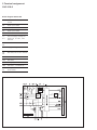
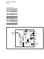
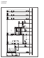
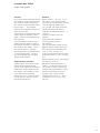
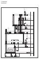
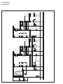
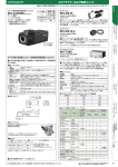
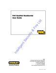
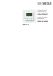
Manual DoorCom IP In-Home DCIP 650-01 Contents 1 System description 3 9 Measured values 29 2 Safety remarks 3 10 Glossary 30 System conditions 3 Index 30 3 Structure DCIP 650-01 4 Autocommunication via the tele phone system with DCA 740-... 5 Terms 6 4 Components for DC IP 650-... Bus door loudspeaker module, Bus call button module, Bus camera module 8 Input modules 9 Programming, video server, DoorCom 10 Interfaces, power supply 11 Software 12 5 Installation wiring diagrams 14 Terminals DCIP 650-01 14 LED displays SIVS 610-0 15 Terminal assignment SIVS 610-0 16 Terminal assignment SII 650-0 17 Single line system 19 Single-line system with DCA 740-... 21 Multiple line system 23 6 Commissioning DCIP 650-01 24 DCIP 650-01Client-Software 26 7 DoorCom DCA 740-01 DoorCom DCA 740-01 28 8 DoorCom IP 28 2 1 System description 2 Safety remarks System conditions: DoorCom IP In-Home Siedle DoorCom IP links the Siedle In-Home bus: Video with the IP world. Door calls are transformed via the DoorCom IP and transmitted via the IP network (Intranet) to certain PCs. The video image at the door station is converted and transmitted via the IP network. Electrical voltage The DoorCom IP Software Client is used here as a virtual in-house telephone for communication to the door station. The Software Client must be installed on every PC in the network which is intended to receive a door call. Switching and control commands can be visualized and operated using the Software Client. Assignment of door calls to the Software Clients takes place using an IWA address (Interface Working Address) which is entered in the DoorCom IP with the aid of the con figuration software. The door call can optionally also be held over the telephone system using a telephone, while the picture is displayed by the Software Client and all control functions such as door release can also be initiated by the software. For this, a DCA 740-01 must additionally be connected to the DoorCom IP. The video camera picture continues to appear in the Software Client on the PC monitor. Mounting, installation and servicing work on electrical devices may only be performed by a suitably qualified electrician. Failure to observe this regulation could result in the risk of serious damage to health or fatal injury due to electric shocks. •When working at the device, observe the remarks relating to mains cut-off. •Observe the standard DIN EN 60065! When establishing the electronic connection, observe the requirements of VDE 0805 / EN 60950. •The building installation must include an all-pole mains switch with a contact separation of at least 3 mm. •Ensure maximum fusing of 16A for the mains connection in the building installation. •When planning, the required distributor space for switch panel mounted devices must be taken into account. •No external voltages >30 V AC / DC may be applied to bus users. Devices with 230 V connection In accordance with DIN VDE 0100 part 410, section 411.1.3 attention must be paid to ensuring a safe separation between system lines and the mains voltage; i.e. system and mains cores must not be permitted to touch! The system line cable (extra-low safety voltage) must be stripped back by the minimum pos sible. Find out about the necessary safety measures and system requirements before starting installation and com missioning of the DoorCom IP. System conditions for the bus programming software BPS 650‑... System requirements, software conditions: • IBM-compatible PC with CD-ROM drive • Intel Pentium III/1 GHz, and compatible CPUs • Main memory with at least 512 MB RAM • Powerful graphics card • Operating systems from Microsoft® Windows 2000/XP/ Vista/Windows 7 (no guarantee with Windows 95, 98SE and 98Me, and Windows NT 4.0 from SP3, as support for these operating systems has now been discontinued by Microsoft) (currently also still without engagement for Windows Vista, USB drivers are already being reworked) • Appr. 25 MB free space on the hard disk (for BPS 650-... incl. help file) • Sufficient free storage space for project data (appr. 5-250 kB per project) • Microsoft Internet Explorer 6.0 or higher • Acrobat Reader 7.0 or higher • Where necessary up to 150 MB free space on the hard disk for additional service packs, Internet Explorer, Acrobat Reader, etc. • The PRI 602‑... USB is required for programming. For mains connection and network settings such as assignment of the IP address, the responsible network administrator must be consulted. 3 3 Structure DCIP 650-01 In-Home bus: Video Audio and video communication via IP In-Home-bus: Video BVVU 650-... BVVU 650-... IPVS 600-… TCP/IP-Network BVVU 650-... PRI 602-... USB DCIP 650-... In-Home bus link The DCIP 650-... behaves in the system in the same way as one or more bus telephones with video and is consequently bound by the same system limitations (range and number of users). The DCIP 650-... comprises the com ponents: • SIVS 610-..., system interface video server. Processing and adjustment of data, audio and video. • SII 650-... system interface In-Home. Interface to Siedle In-Home bus. • IPVS 600-..., IP video server. Processing and adjustment of audio and video, transmission of data, audio and video to the IP network. One DCIP 650-... each is required per door. A maximum of 29 different call destinations can be dialled. Dialling is possible by means of a call button module, code lock module or display call module. • Bus programming software BPS 650-... V2.50 for programming • Software Client DCIP SC 600-... for installation on PC users intended to receive door calls. 4 VNG 602-... Power supply The DCIP 650-... is supplied com pletely via the video line rectifier VNG 602-... . Connection takes place at the SIVS 610-... An optionally connected DCA 740-01 is also supplied from the SIVS 610-... . The a/b public network interface is supplied from the TC system. It is not possible to connect an individual public network telephone directly to the a/b line of the DCA 740-01. Functions • Door call from the In-Home bus and signalling • Text display of which door or which bus telephone is calling. • Door release actuation • Light actuation • Direct dialling and connection to a door station or a bus telephone. • Initiation of switching or control functions • Reception of status messages from the In-Home bus Mounting and installation Connection of the DCIP 650-... to the In-Home bus takes place at terminals TaM/TbM at the SII 650-... on the monitor branch. Dual termi nals TaM/TbM are provided for loop through. Connection can alterna tively take place using a distributor BVVU 650-... . The devices are intended for switch panel mounting. These should preferably be mounted directly one next to the other. The maximum conductor length for device connection between SIVS 610-... and SII 650-... may be 1 metre. The SII 650-... is linked to the SIVS 610-... with 6 cores. Commissioning and programming After connection of the supply voltage, the devices SII 650‑... and SIVS 610‑... can be programmed with the aid of a PRI 602‑... via the PC. Prior to commissioning the DoorCom IP, the entire In-Home system must be programmed. The components SII 650-..., SIVS 610-... and BVNG 650-... which are in the same line must have the same address set. Programming of the SIVS 610-... and SII 650-... takes 3 Autocommunication via the telephone system with DCA 740-... Video communication via IP In-Home-bus: Video telephone system BVVU 650-... BVVU 650-... IPVS 600-… TCP/IP-Network BVVU 650-... PRI 602-... USB place with bus programming soft ware BPS 650-... No programming is required for the DCA 740-01. For programming and configuration of the TC system, see the relevant product information and programming instructions of the manufacturer. Performance features DCIP 650-01 DoorCom IP In-Home • Transfer of door calls with/without video • Audio transmission possible via the telephone network (DCA 740-...) • Actuation of the door release and light. • Selective connection to a door sta tion. (Audio and/or video) • Speech connection is possible both to In-Home doors (across lines) and also to In-Home telephones (only within a line) • Doors and bus telephones can be selectively connected / called • Devices such as BSE 650-..., BSM 650-... etc. can be actuated across different lines. (but not bus telephones) VNG 602-... • Capacity to manage up to 100 messages / 100 functions • Parallel calls (bus telephones and SII users) are possible • Pure video connections can also be established to the In-Home bus • Communication to the SIVS 610-... takes place via the bidirectional SUS interface with the Vario bus protocol • Programming takes place via the SUS interface and via the USB-PRI 602-... • Firmware update possible via the SUS interface • The address setting for connection to the Vario bus takes place via a BCD rotary encoding switch • Max. 31 users possible per DCIP 650-... 5 3 Terms Client PC user connected to a network. Full duplex Two speaking users e.g. door sta tion and remote station have an unrestricted speech connection. Open duplex communication, i.e. as opposed to the simplex speech mode. Gateway Gateways link two different sys tems and create connections across network boundaries. During this process, both the physical transmis sion modes and also protocols and addresses are adjusted accordingly. Half duplex Two speaking users have one speech connection which they can use alter nately, also known as push to talk. The speech direction is controlled by the user via the PC client. HTTP The Hypertext Transfer Protocol is a protocol used for the transmission of data via a network. It is used mainly to load websites and other data from the Internet into a web browser. Hub The term hub when used in relation to network technology describes a device which links network nodes in a star formation. Normally, the term hub is used to denote a multiport repeater. It is used in order to link network nodes or other hubs, for example by means of an Ethernet. IP address Internet Protocol address An IP address is a number which permits PCs and other devices in an IP network to be addressed. In tech nical terms, the number is a 32-or 128-bit binary number. 6 IP Internet Protocol The IP is a network protocol in wide spread use in computer networks. IP forms the first layer of the Internet protocol family which is independent of the transmission medium. This means that computers can be grouped within a network into logical units known as subnets by means of an IP address and subnet mask. IGMP V3 The Internet Group Management Protocol is based on the Internet Protocol (IP) and permits IP multi casting (group communication) in the Internet. IP multicasting is the distribution of IP packages under an IP address to several stations simultaneously. Here, it is possible to specify which source is required for the multicast stream. IWA Interface working address Six-digit address with which the system interface video server e.g. SIVS IP 610-... addresses the users. LAN Local Area Network Local, cable-linked network. Multicasting Term to denote group/parallel calls with video image to several PC users which have the Software Client installed. For this to be possible, the UDP and IGMP V3 protocols must be implemented in the network. Push to Talk In case of a connection using the half duplex mode (push-to-talk) a button always has to be pushed to change the speech direction. Router A router is a network device which links several computer networks. Network packages of a protocol arriving at the router are analysed for information and forwarded or routed to the intended destination network. RS232 Designation for a serial interface, for instance the COM interface of a PC. RS485 Interface for serial data transmis sion in the half duplex mode. Transmission to a pair of cores. Server A server is a program which waits to be contacted by a client program, after which it exchanges data with the client program. The hardware on which the server runs is known as the host. Subnet mask The subnet mask, also known as network mask, is a bit mask which separates an IP address into a net work and a device or host section. It is used in IP networks in order to make routing decisions. SUS Siedle Universal Interface TCP Transmission Control Protocol The TCP is a protocol which deter mines the way in which data is exchanged between computers. All operating systems in modern computers have TCP capability and use this protocol for data exchange with other computers. The protocol is a reliable, connection-oriented transport protocol used in computer networks. It is part of the internet protocol family, which forms the foundation of the Internet. UDP User Datagram Protocol The UDP is a minimal connectionless network protocol which belongs to the transport layer of the Internet protocol family. It is the task of the UDP to assign data transmitted via the network to the right application. USB The universal serial bus (USB) is a serial bus system for connection of a computer to external devices. Devices or storage media equipped with USB can be connected in run ning operation, and connected devices and their characteristics automatically detected. Vario bus Various different input and control units can be connected to the Vario bus. It comprises 4 cores. The infor mation on the Vario bus is trans mitted via the RS485 protocol. Web browser Software for the display and indi cation of Internet pages or corre sponding configuration pages. e.g. Internet Explorer or Firefox. 7 4 Components for DC IP 650-... Bus door loudspeaker module, Bus call button module, Bus camera module BTLM 650-04 Bus door loudspeaker module for In-Home bus. Loudspeaker and microphone integrated, illuminated light button, integrated door release contact (DR) Acoustic acknowledge ment on pressing a button, can be activated if required with the BPS 650-... . contact load max. 15 V AC / 30 V DC / 2 A, switching BTM 650-01 - BTM 650-04 Bus call button modules for In-Home bus 1-4 call buttons, integrated LED lighting. Connection by means of ribbon cable to the bus door loud speaker. Supply to the LED lighting via terminal b and c with 12 V AC, current consumption 20 mA per bus call button module BTM 650-... BCMC 650-0 Bus colour camera module for Siedle In-Home bus: Video. Integrated 2-step heating, day/night switching, infrared lighting and video signal converter. Supply via Siedle In-Home bus: Video, heating supply 12 V AC, 100 mA. 8 time DR fixed at 3 seconds. Acoustic feedback when actuating the call buttons. 4 Components for DC IP 650-... Input modules COM 611-02 Code lock module as an input unit for the placement of codes for con trol functions in conjunction with the Siedle Vario bus. • With keypad for making calls or • For controlling in conjunction with the Easikey controller EC 602... • C button for cancelling incorrect inputs • DR button for direct door release via the EC 602-... Operating voltage: 12 V AC Operating current: max. 100 mA Protection system: IP 54 Ambient temperature: -20°C to +55°C Dimensions (mm) W x H x D: 99 x 99 x 27 DRM 611-01 Display call module as an input device with 4-line display for placing door calls. Indication of names in the display in alphabetical order. The DRM 611-... can also be used in combination with the COM 611-... in order to display the input via the COM 611-... . Operating voltage: 12 V AC Operating current: max. 200 mA Protection system: IP 54 Ambient temperature: -20°C to +55°C Dimensions (mm) W x H x D: 99 x 99 x 27 9 4 Components for DC IP 650-... Programming, video server, DoorCom IPVS 600‑01 System interface video server Processing and adjustment of audio and video; transmission of data, audio and video to the IP network. Dimensions 118 x 88 x 48 mm DCA 740-01 DoorCom Analog DCA 740-01, in switch panel housing, can be con nected to a universal a/b interface. In conjunction with the DCIP 600/650/740-... it serves as an alternative speech connection if no speech connection via PC is preferred. Connection takes place at the standardized a/b interface of a telephone system (analog PBX PRI 602-01 USB Programming interface for connec tion of a Windows PC via USB port to the ZBVG 650-... interface. The ZBVG 650-... is plugged into bus line rectifier BNG/BVNG 650-... . Commissioning, programming and servicing facility for the In-Home bus using BPS 650-... software. 10 extension) or directly at the analog telephone network. Operating voltage: 15 V DC Protection system: IP 20 Ambient temperature: 0°C to +40°C Horizontal pitch (HP): 6 Dimensions (mm) W x H x D: 107 x 89 x 60 4 Components for DC IP 650-... Interfaces, power supply SIVS 610-0 System interface video server for connection of the In-Home bus: Video to IP video server. The SII 650-... is required for connection. Dimensions 144 x 130 x 55 mm SII 650-0 The system interface In-Home con verts the signals from the In-Home bus: Video for the SIVS 610-... Dimensions 107 x 89 x 60 mm VNG 602-02 Video line rectifier in a 10-grid housing. Primary: 230 V AC, 50/60 Hz Secondary: 30 V DC, 1.1 A stabi lized. For supply to the SIVS 610-... and the connected interfaces. BVNG 650-0 Bus video line rectifier in a 9-grid housing. Primary: 230 V AC, 50/60 Hz, Door release contact 15 V AC, 30 V DC, 2 A, switching time fixed at 3 sec onds. Light contact 15 V AC, 30 V DC, 2 A, switching time 0.4 seconds, capable of being changed with bus programming software BPS 650-... 11 4 Software BPS 650-0 from V2.50 Bus programming software for pro gramming In-Home bus systems. For this, the programming interface PRI 602-... is also required in con junction with a BIM 650-... or the PRI 602-0 USB. DCIP SC 600-0 DoorCom IP Software Client PC programm describing a virtual in-house telephone with video on a PC monitor. Door calls with video are possible to one or more Siedle door stations. Implementing switching and control functions e.g. door release, light switching or indication of messages on the PC monitor. A licence of the DCIP SC 600-... is required for every installation of the Software Client on a PC. 12 System conditions: • Operating system Microsoft® Windows XP Professional (from SP2, 32 Bit), Microsoft® Windows Vista Home Premium and Business (from SP1, 32 Bit) • Intel® Pentium® IV from 2.0 GHz or compatible CPUs • min. 1 GB RAM Graphics card with at least 1024 x 768, 128 MB and 16 bit colour depth DirectX 9.0 support • Ethernet card 100 Mbit • Sound card including headset adapter • Microsoft® DirectX® 9.0c • Microsoft® Internet Explorer® latest version to read the help 5 Installation wiring diagrams Terminals DCIP 650-01 a b c Terminals and LEDs IPVS 600‑01 a 12 V DC power input for connecting the power supply b Connecting socket to the SIVS 610‑... c LED LINK lights up in green with an existing network connection d RJ45 socket ETH network connection e LED ACT lights up in orange on data transmission via the network d e f g j h Terminals and LEDs IPVS 600‑01 f Video input 1 Vss from the SIVS 610‑... g Card slot for SDTM card (no function) h Audio-Line-In/Audio-Line-Out to the SIVS 610‑... i LED operating status lights up in green on readiness for operation j Reset button to recreate the asdelivered status (after a reset, the Siedle modes must be reinstalled, see Chapter Factory reset.) i Terminals SIVS 610-... a Video signal 1 Vss (cinch jack) b Terminating resistor 75 Ohm ON/OFF c IN = video signal 1 Vss input, D =video signal 1 Vss throughput d Terminals for installation e Connection to IPVS 600-... f Terminals for installation g Grounding terminal h BCD rotary switch for the In-Home bus line address 13 LED displays SIVS 610-0 LED signalling IPVS 600-... The IP video server IPVS 600-... has 3 LEDs which can display operating statuses and can provide an indication of possible errors: LED power on the top and the LED LINK and LED ACT on the underneath. LED Power Function OFF IPVS 600-... is switched off. Lights up in green IPVS 600-... is switched on Flashes green Access to the IPVS 600-... Lights up in red (briefly) Start process running Lights up in red (continuous) Error in the device or failed upload LED LINK Lights up in green Network connection exists LED ACT Lights up in orange Active data transmission via the network LED signalling SIVS 610-... Switching on LED green LED red Function OFF ON After reset, power on: Device boots to operating status. ON ON The boot area is checked. Software runs in the flash Fast flashing ON After a software update, the boot area is recreated. This can take up to around 3 minutes. LED green LED red Function ON OFF Booting is complete. All OK. Normal status Slow flashing OFF Display, a connection exists Fast flashing OFF A software update or reconfiguration process is under way LED green LED red Function OFF Slow flashing ERROR, software running only in bootloader. Program memory defective. (Device defective, possibly new software update or exchange.) ON Slow flashing Vario bus address error (error remedy possible on site) ON Fast flashing The 12 V power supply (terminal bv, cv) is overloaded. (Error remedy possible on site) OFF OFF If supply voltage is definitely connected, the device is defective. (Exchange) Operation Fault Frequencies: Slow appr. 2 Hz, fast appr. 16 Hz 14 LED signalling SII 650-... The system interface In-Home bus SII 650-... is fitted with 2 LEDs under the device lid which display operating statuses and provide an indication of possible faults. Switching on LED1 LED2 Function OFF ON Power On or Reset: Device boots to operating status. ON OFF Operating status display Slow flashing OFF Operating status display with active connection ON Fast flashing Variobus address error (error remedy possible on site) Fast flashing OFF updating Firmware Update Frequencies: Slowly appr. 1 Hz, quickly 2 Hz, flashing appr. 16 Hz 15 5 Terminal assignment SIVS 610-0 Block diagram SIVS 610-0 G Reference for the inputs E1–E4 E4 Input 4, not used E4 Input 3, not used E4 Input 2, not used E4 Input 1, not used cvbv+ Pick off supply voltage for Vario bus, 12 V DC, max. 300 mA Da/ Db Vario bus + - Supply voltage 24-30 V DC DR DR Not used, DR via TLC 640-02 Li not used USP Not used SN1 RF signal, path SN2 SIM 740-... to SIVS 610-... n1 n2 RF signal for connected DCA 740-01 16 5 Terminal assignment SII 650-0 Block diagram SII 650-0 TaM/TbM In-Home bus: Video Input and output E1+/E1- Input for signalling function, 4-30 V DC or 4-20 V AC S1/S1 relay contact max. 24 V, 2 A SN1/GND RF signal Out SN2/GND RF signal In SaV/SbV In-Home bus internal connection bv/cv Terminal of the supply voltage for Vario bus Da/Db Vario bus 17 c b TR 603-... a) Siedle Vario BCMC 650-... BTLM 650-... BTM 650-... c) Remarks L1 N c c TÖ 12 V AC min. 20 Ohm b b GND Vc Tb Ta Ta Tb Vc GND Device requirement BTM IN BTLM TaK TbK b) BVNG 650-... ZBVNG 650-... L1 N Sb Sa Tö Tö Li Li TaM TbM TaK TbK PRI 602-... USB SII 650-... Sb Sa Db Da cv bv M1 GND SN2 SN1 S1 S1 E1+ E1- TaM TbM TaM TbM VNG 602-... L1 N -M +M input signal 4 - 30 V DC, 10 mA Db Da cv- bv+ Video IN - + SN2 SN1 f) SIVS 610-... Link IP 18 IPVS 600-... ETH LineIn/Out RS232 VideoIn VideoIn ERT Ethernet RJ45 BCMC d) BTSV 850-... ERT ETb TaM TbM TaM TbM ERT TaM TaM TbM d) BFSV 850-... ERT ETb TbM ERT TaM d) e) BTCV 850-... ERT ETb TbM 5 Installation DCIP 650-01 230 V AC 230 V AC 230 V AC In-Home bus Video Single line system Function Up to 29 PC users (Software Clients) of a network can be called from the door station. Calling, speech and door release via the Software Client DCIP SC 600-... . The Software Client must be installed on every PC which receives calls. Call functions of the Software Client 3-tone chime as standard, a dedi cated *.wav file can be assigned for each call tone. It is not possible to listen in to an existing call from other PC users in the network. The door is opened by the called PC user using a “virtual door release button”, the light switching function is actuated using a “virtual light button”. The door call can be muted with an optical display on the monitor. Supplementary functions • Additional PC users can be imple mented with an additional line. • Up to 10 PC users can be called in parallel with a call button from the door station. Up to 49/45 PC users are possible at one IPVS 600-... . Reduction to 45 PC users can result if 10 or more PC users are config ured as parallel devices. Remarks a) The TR 603‑... (12 V AC, 1.3 A) can supply 1 door release button and max. 24 bus call button modules with LED lighting (BTM 650‑01, ‑02, ‑03 and ‑04). With more than 24 illuminated bus call button modules, an additional TR 603‑... is required. Current consumers in the AS diagram: Door release appr. 600 mA Camera heating 100 mA LED lighting Per bus call button module 25 mA b) Door release contact load in the bus video line rectifier BVNG 650-... max. 15 V AC, 30 V DC, 2 A. • Light contact load in the bus video line rectifier max. 15 V AC, 30 V DC, 2 A. c) Door release 12 V AC, use at least 20 Ohm (e.g. TÖ 615‑...). f) Distance of the BVNG 650‑.../ SII 650‑... to the door station max. 100 m with J-Y(ST)Y 0.8 mm core material. During installation, ensure that the door release is laid in a separate cable. Supply voltage available from SIVS 610‑... at the terminals bv+/cv- 12 V DC, max. 300 mA. 19 20 c b TR 603-... a) Siedle Vario BCMC 650-... BTLM 650-... BTM 650-... c) Remarks L1 N c c TÖ 12 V AC min. 20 Ohm b b GND Vc Tb Ta Ta Tb Vc GND Device requirement BTM IN BTLM TaK TbK b) BVNG 650-... ZBVG 650-... L1 N Sb Sa Tö Tö Li Li TaM TbM TaK TbK PRI 602-... USB SII 650-... Sb Sa Db Da cv bv M1 GND SN2 SN1 S1 S1 E1+ E1- TaM TbM TaM TbM VNG 602-... L1 N -M +M input signal 4 - 30 V DC, 10 mA n1 Db Da cv- bv+ Video IN - + SN2 SN1 n2 f) SIVS 610-... Link IP BCMC IPVS 600-... ETH LineIn/Out RS232 VideoIn n1 g) DCA 740-01 Lb La Db Da c- b+ n2 Analog telephone connection to TBR 21 5 Installation DCIP 650-01 Ethernet RJ45 230 V AC 230 V AC 230 V AC In-Home bus Video Single-line system with DCA 740-... Function Up to 29 PC users (Software Clients) of a network can be called from the door station. Calling and door release via the Software Client DCIP SC 600-... . The Software Client must be installed on every PC which receives calls. The door call is switched via the DCA 740-... to the telephone system. A connected telephone can accept the door call. Call functions of the Software Client 3-tone chime as standard, a dedi cated *.wav file can be assigned for each call tone. It is not possible to listen in to an existing call from other PC users in the network. The door is opened by the called PC user using a “virtual door release button”, the light switching function is actuated using a “virtual light button”. The door call can be muted with an optical display on the monitor. Supplementary functions • Additional PC users can be imple mented with an additional line. • Up to 10 PC users can be called in parallel with a call button from the door station. Up to 49/45 PC users are possible at one IPVS 600-... . Reduction to 45 PC users can result if 10 or more PC users are config ured as parallel devices. Remarks a) The TR 603‑... (12 V AC, 1.3 A) can supply 1 door release button and max. 24 bus call button modules with LED lighting (BTM 650‑01, ‑02, ‑03 and ‑04). With more than 24 illuminated bus call button modules, an additional TR 603‑... is required. Current consumers in the AS diagram: Door release appr. 600 mA Camera heating 100 mA LED lighting Per bus call button module 25 mA b) Door release contact load in the bus video line rectifier BVNG 650‑... max. 15 V AC, 30 V DC, 2 A. • Light contact load in the bus video line rectifier max. 15 V AC, 30 V DC, 2 A. c) Door release 12 V AC, use at least 20 Ohm (e.g. TÖ 615‑...). d) Conductor length bus telephone storey call button ERT max. 50 m. e) When using the internal video memory module, the bus telephone BTCV 850‑... must be supplied by an additional direct voltage (20 - 30 V DC, 350 mA). NG 602‑... or VNG 602‑... can be used for this purpose. Connection of the power supply to terminals +M/-M. f) Distance of the BVNG 650‑.../ SII 650‑... to the door station max. 100 m with J-Y(ST)Y 0.8 mm core material. During installation, ensure that the door release is laid in a separate cable. Supply voltage available from SIVS 610‑... at the terminals bv+/cv- 12 V DC, max. 300 mA. The DCA 740‑01 can optionally be connected to the PBX extension of a telephone system. Active door calls can then be routed via the telephone. The functions of the IP interface still remain possible. 21 TR 603-... a) Siedle Vario BCMC 650-... BTLM 650-... BTM 650-... c) Remarks L1 N c c TÖ 12 V AC min. 20 Ohm b b GND Vc Tb Ta Ta Tb Vc GND b c Device requirement BTM IN BTLM TaK TbK b) BVNG 650-... ZBVNG 650-... ZBVG 650-... L1 N SbV SaV Sb Sa Tö Tö Li Li TaM TbM TaK TbK PRI 602-... USB h) SII 650-... Sb Sa Db Da cv bv M1 GND SN2 SN1 S1 S1 E1+ E1- TaM TbM TaM TbM VNG 602-... L1 N -M +M input signal 4 - 30 V DC, 10 mA Db Da cv- bv+ Video IN - + SN2 SN1 f) SIVS 610-... Link IP 22 IPVS 600-... ETH LineIn/Out RS232 S1 b) BVNG 650-... ZBVNG 650-... L1 N SbV SaV TaM TbM h) SII 650-... Sa Sb Sa Db Da cv bv M1 GND SN2 SN1 Sb Tö Tö Li Li S1 E1+ E1- TaM TbM TaM TbM VNG 602-... L1 N -M +M input signal 4 - 30 V DC, 10 mA SN1 Db Da cv- bv+ Video IN - + SN2 f) SIVS 610-... Link IP BCMC RS232 IPVS 600-... ETH LineIn/Out 5 Installation DCIP 650-01 Ethernet RJ45 230 V AC Ethernet RJ45 230 V AC 230 V AC 230 V AC In-Home bus Video Multiple line system Function Up to 29 PC users (Software Clients) in a network can be called per SII 650‑... . In a multiple-line system, several lines are connected. The line address must be set the same at each BVNG 650‑..., SIVS 610‑... and SII 650‑... . In each line, a maximum of one DCIP 650‑... may be used. In a multiple-line system with 2 lines, this means that 60 users can be called form a door station. Calling and door release via the Software Client DCIP SC 600‑... . The Software Client must be installed on every PC which receives calls. The door call is switched via the DCA 740‑... to the telephone system. A connected telephone can accept the door call. Call functions of the Software Client 3-tone chime as standard, a dedicated *.wav file can be assigned for each call tone. It is not possible to listen in to an existing call from other PC users in the network. The door is opened by the called PC user using a “virtual door release button”, the light switching function is actuated using a “virtual light button”. The door call can be muted with an optical display on the monitor. Supplementary functions • Additional PC users can be implemented with an additional line. • Up to 10 PC users can be called in parallel with a call button from the door station. Up to 49/45 PC users are possible at one IPVS 600-... . Reduction to 45 PC users can result if 10 or more PC users are configured as parallel devices. Remarks a) The TR 603‑... (12 V AC, 1.3 A) can supply 1 door release button and max. 24 bus call button modules with LED lighting (BTM 650‑01, ‑02, ‑03 and ‑04). With more than 24 illuminated bus call button modules, an additional TR 603‑... is required. Current consumers in the AS diagram: Door release appr. 600 mA Camera heating 100 mA LED lighting Per bus call button module 25 mA b) Door release contact load in the bus video line rectifier BVNG 650‑... max. 15 V AC, 30 V DC, 2 A. • Light contact load in the bus video line rectifier max. 15 V AC, 30 V DC, 2 A. c) Door release 12 V AC, use at least 20 Ohm (e.g. TÖ 615‑...). f) Distance of the BVNG 650‑.../ SII 650‑... to the door station max. 100 m with J-Y(ST)Y 0.8 mm core material. During installation, ensure that the door release is laid in a separate cable. Supply voltage available from SIVS 610‑... at the terminals bv+/cv- 12 V DC, max. 300 mA. The DCA 740‑01 can optionally be connected to the PBX extension of a telephone system. Active door calls can then be routed via the telephone. The functions of the IP interface still remain possible. g) The DCA 740‑01 can optionally be connected to the PBX extension of a telephone system. Active door calls can then be routed via the telephone. The function of the IP interface remains possible. h) Each SII 650‑... must be programmed with the bus programming software BPS 650‑... and the programming interface PRI 602‑... USB. 23 6 Commissioning DCIP 650-01 A number of steps have to be executed for commissioning the DCIP 650-... . The specified sequence must be adhered to without fail. • Prior to programming the DoorCom IP 650-... the entire In-Home system must be pro grammed and documented with the bus programming software BPS 650-... . • Complete programming of the DoorCom IP 650-... takes place using the bus programming software BPS 650-... via the SII 650-... 24 Connection of the PC to SII 650‑... Step 1 Issue of the IP address and subnet mask in the IPVS 600‑... • The connection can be established using a crossover network cable. The IPVS 600‑... can also be addressed via the network if the PC and IPVS 600‑... are located in the same address area. • Start the Internet Explorer on the PC and enter the following in the address line: http://192.168.0.1 The IP settings in the as-delivered status of the IPVS 610-... IP address: 192.168.0.1 Subnet mask: 255.255.255.0 Gateway address: 0.0.0.0 User name: Service Password: None issued on delivery The user interface is opened. • Select the Expert mode menu item. • UnderExpert mode select the menu point Network • The following settings can be performed for operation in the network: DHCP IP address Subnetmask address Gateway address DNS server address Changes to the IP address, subnet mask address or gateway address are transmitted to the device by clicking on the Set button. However, these only become valid after restarting the device. • After entering a new IP address, click onto the Set button • Enter the old IP address in the address line of the web browser, followed by /reset (e.g. 192.168.0.11/reset). The IPVS 600 is restarted and can subsequently only be reached using the new IP address. The connection is established between the PC and IPVS 600 ... . Changes to the IP address or subnet mask address are transmitted to the device by clicking on the Set button. However, these only become valid after restarting the device. • After entering a new IP address, click onto the Set button. • Enter the old IP address in the address line of the web browser, followed by /reset (for example 192.168.0.1/reset). The IPVS is restarted and can subsequently only be reached using the new IP address. Step 2 Read out In-Home bus All existing devices within the In-Home bus are read in and are then visible in the BPS 650‑... as a tree structure. Each BVNG 650‑... possesses a unique address. This must be set the same at the SII 650‑... and SIVS 610‑... . Step 3 (only with multiple line system) Manually add SII 650‑... In the BPS 650‑... , select the relevant line and add the SII 650‑... The address of BVNG 650‑..., SIVS 610‑... and SII 650‑... must be set the same. An already programmed SII 650‑... is automatically detected by the BPS 650‑... . Step 4 Create virtual users In the first table DCIP-SC (virtual users) create the users. Each user should be given a unique name wherever possible such as Secretarial. Step 5 In the tree structure of the BPS 650‑... , select the relevant door station and assign the users to the previously created call buttons. Subsequently transfer the configuration to SII 650‑.../ SIVS 610‑... Step 6 In the tree structure of the BPS 650‑..., select the SII 650‑... . Pressing the Configuration button in the DCIP-SC... will open a new window. In this window, it is possible to select which users are read out to the configuration being created. In this selection process, different configurations can be generated for different software clients. Step 7 The set configuration (*.dcip) can be imported into Software Client. A USB stick is advisable for transmission of the files. 25 7 Client-Software DCIP SC 600-0 Installation of the Software Clients The Software Client DCIP SC 600-... (Ver. 1.1. or higher) must be installed on each PC which is intended to receive door calls. The Software Client communicates with the remote station, the DCIP 650-... Following the installation, the file (*.dcip) generated by the bus pro gramming software BPS 650-... must be imported. The addresses to which the client is intended to respond are selected from the imported file. System requirements for the Software Client • Operating system Microsoft Windows XP/Vista 32 Bit with the latest service packs • Computer Pentium IV from 2 GHz with a storage capacity of at least 1 GB RAM, • Graphic card with at least 1024 x 768, 16 bit colour depth and latest driver updates, Nvidia Geforce6600, Nvidia Quadro FX1400, ATI RADEON 9800/X600/ X800, • 100 Mbit Ethernet card • Sound card and • Microsoft DirectX 9.0c. Procedure for installation • Install the DCIP SC 600 software • It may be necessary to install addi tional programs such as Microsoft DirectX Version 9.0c. • Start the Software Client • The Software Client configuration can be opened by pressing the right hand mouse button on the virtual in-house telephone. • In the first tab Configuration, select add DCIP SC file and import the file exported by the configura tion software (*.dcip). • It is then possible under DCIP SC-Edit file to assign an IWA address to the Software Client for the relevant DCIP 650-..., to which you wish the PC to respond. 26 • Other IWA addresses can option ally be assigned to the Software Client 2. (e.g. for receiving an addi tional door call). Licence regulations For each installation of the Software Client on a PC, a licence is required for the DCIP SC 600‑0. The standard ex works DCIP 650‑... includes 4 licences. Any additional licences required must be subsequently purchased. Audio transmission The quality of the audio transmission via the Software Client DCIP SC 600-0 at the PC depends largely on the equipment of the PC or the sound card used in it, and consequently cannot be directly influenced by the PC software. If a secured audio transmission in TC quality is required, or if an audio connection must always be possible to and from the door irrespective of your network or the status of the PC, then we recommend using our DCA 740-01. Possible error sources • No speech connection from the PC to the door. The microphone amplifier may not be activated. • Installation must take place as administrator, so that all registered users have access to the Software Client later. • Marked echo on the line in speech mode. In the Windows volume regulation for sound reproduction, Sound off must be activated under the microphone controller. This selection prevents the PC microphone signal being reproduced in the PC loudspeaker. • The other party is not audible at the PC. Possible causes: • No loudspeaker connected at the PC/monitor • No driver for the sound card • The loudspeaker is set to mute under the audio properties. (sound off) • If there is an active firewall, the application file DCIP SC 600-0.exe must be defined as an exception or as a permanently authorized program/application. • In order to establish a video link, it may be necessary, for the drivers for the used graphic card to be updated to the latest status. Other settings in the Software Client: Free buttons Selection of functions for buttons 1-3. Each button can be assigned an individual inscription text. Ringtones Selection of call tones for door call and internal call. Alternatively, you can select your own *.wav files. Setting the volume for call tones Speech volume Setting the speech volume. Loudspeakers and microphones can be separately set. It may be neces sary to carry out other settings in the control panel under “Sound”. General Selection of the Software Client language. “Start application automatically after logging onto the system?” 27 7 DoorCom DCA 740-01 8 DoorCom IP Factory setting IPVS 600-... The DoorCom Analog DCA 740-... is used as an interface between DoorCom IP and an analog tel ephone connection of a telecommu nication system. With the reset button at the IPVS 600‑..., it can be reset to the as-delivered status. It is essential to load the Siedle factory configuration in the IPVS 600‑... after a reset. Proceed as follows. 1 Start the Internet Explorer on the PC and enter the following in the address line: http://192.168.0.1 The IP settings in the as-delivered status of the IPVS 610‑... User name: Service Password: None issued on delivery The user interface is opened. 2 Select the Expert mode menu item 3 Under Expert mode select the menu point Maintenance. 4 Under Configuration select "Search“ to find the configuration file and select. The file is on the supplied CD. 5 Select the file rtc_image. 6 Start the update with "Upload". It is possible to assign the maximum number of possible users in a line to the DCA 740-... . The functionality depends in the main on the capa bility of the telephone system /on the telephones connected to it. Assignments and functionality for calls via the DCA 740-... are saved in the SII 650-... . This can be programmed using BPS 650-... if the connection via DCA 740-... is selected. The selection of users and control and switching functions takes place by means of DTMF dialling. The telecommunications system and the connected telephones must there fore possess DTMF dialling capability. Power supply The DCA 740-... is supplied directly from the SIVS 610-... . A separate supply is consequently not required. The power to the a/b public net work interface is supplied from the telecommunication system or the a/b public network connection from the exchange. It is not possible to connect an individual public network telephone directly to the a/b line of the DCA 740. 28 9 Measured values Measurement values for DoorCom IP, to be measured using a digital multimeter Idle status min. Voltage +/ at the SIVS 610-... 24 V DC Current consumption max. 30 V DC 500 mA Conductor lengths VNG 602-... supplies 1 DCIP 650-... 100 m VNG 602-... supplies 2 DCIP 650-... 50 m 29 10 Glossary Index As-delivered status 29 Block diagram 18 Client26 Commissioning24 Config 24 DoorCom10 Factory setting 29 IP6 IP address 6 IWA6 LED display 15 Licences26 Line rectifier 12 Power supply 4, 6 Programming24 Server8 Software Client 26 Subnet mask 6 System interface video server 15 System requirements 2, 26 TCP6 Terminals14 Wiring diagram 18 BTLM 650-04 BTM 650-... BCMC 650-... BPS 650-0 BVNG 650-... COM 611-... DCA 740-... DCIP SC 600-0 DRM 611-... IPVS 600-... PRI 602-... SIVS IP 610-... SII 650-0 VNG 602-0 30 8 8 8 13 12 9 12 13 9 10 12 12 12 12 The current issue of the “DoorCom IP” system manual is available from the download area under www.siedle.de. Technical additions or printing errors do not constitute grounds for compensation claims. 31 S. Siedle & Söhne Telefon- und Telegrafenwerke OHG Postfach 1155 78113 Furtwangen Bregstraße 1 78120 Furtwangen Telefon +49 7723 63-0 Telefax +49 7723 63-300 www.siedle.de [email protected] © 2008/07.12 Printed in Germany Best. Nr. 0-1101/337158 EN