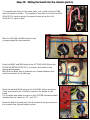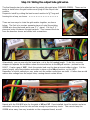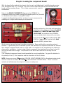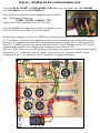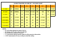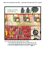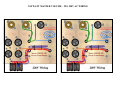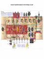
1
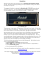
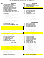
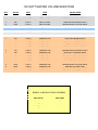
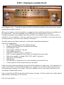
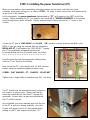
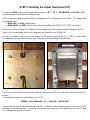
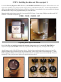
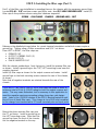
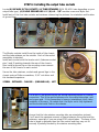
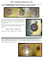
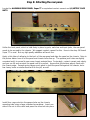
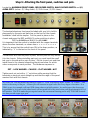
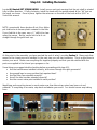
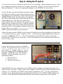
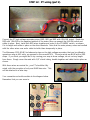
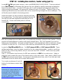
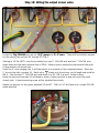
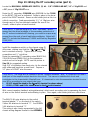
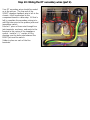
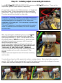
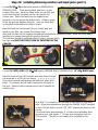
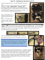
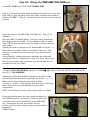
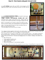
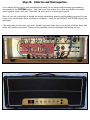
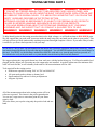
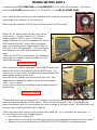
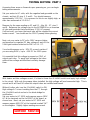
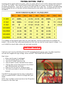
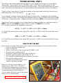
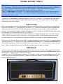
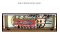
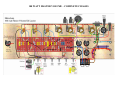
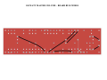
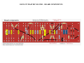
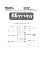
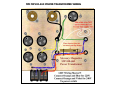
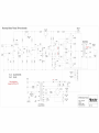
METROAMP 100 WATT MASTER VOLUME
STEP-BY-STEP INSTRUCTIONS
V 1.2 AUGUST 2009
COPYRIGHT © 2009 METROPOULOS AMPLIFICATION INC
Introduction
Welcome to the step-by-step instructions for the Metroamp 100 Watt Master Volume
amp kit. We hope you will enjoy building your amp and will learn a thing or two about
tube amps in the process.
The purpose of this kit is to replicate the Marshall model # 2203 JMP amps produced
from 1976 until 1980. The first Marshall amps to feature a master volume control,
cascaded preamp channels, rocker switches and large 11” Marshall logo.
1979 Marshall 2203
These amps are, in my opinion, THE workhorse 100W amp for rock music. But they also
cover many other styles gracefully. These amps are also ideal for modification. Anything
from a minor tweak to an over-the-top multi-channel, high gain transformation.
We have taken great care to re-create many nuances and details of the original Marshall
2203, but there are a few notable exceptions, each with a specific purpose. Most
notably, our use of a point-to-point terminal board vs. the original PC board. This is to
accommodate larger, discreet components and to allow easy tweaking of the circuit. We
also manufacture our steel chassis to use modern style impedance and voltage selector
switches, which are more reliable than their vintage counterparts.
This kit also features more options than any other Metroamp kit. Each builder has their
choice of several available options:
• Mercury Magnetics or Metroamp brand transformers
• EL34 or 6550 output tubes (both types were found stock on original 2203’s)
• Optional ZERO LOSS FX loop™
• Any of our tweaked 2203 mod options
Enjoy your kit experience and feel free to contact us with any questions or concerns at:
[email protected]
Tech support and lots of technical information are available in our online forum and wiki.
Visit the forum at: http://www.metroamp.com/forum
And the wiki at: http://www.metroamp.com/wiki
100 WATT MASTER VOLUME - BILL OF MATERIALS
QTY
1
1
1
1
1
4
4
1
DESCRIPTION
JMP STYLE LARGE HEADBOX
METROAMP WHITE SCRIPT LOGO
100W MV STEEL CHASSIS
BRUSHED ALUMINUM FRONT PANEL
BRUSHED ALUMINUM REAR PANEL
M6 METRIC CAGE NUT
M6 - 30mm CHASSIS SCREW, WASHER
COMPONENT BOARD – RED 11 5/8” x 3 1/8”
6
1
8
28
10
6
10
1/2" GROMMET
3/8" GROMMET
#10- 3/8" SCREW, WASHER, NYLOC NUT
#6- 3/8" SCREW, NYLOC NUT
#4- 3/8" SCREW, NUT
#4- 1 1/4" BOARD MOUNTING SCREW ASSEMBLY
GROUND LUG - 2 HOLES
1
1
1
STOCK TRANSFORMERS
METROAMP 1203-80-MS - POWER
METROAMP C1998 - OUTPUT
MERCURY MAGNETICS MMC-3H - CHOKE
1
1
1
OPTIONAL TRANSFORMERS
MERCURY MAGNETICS MP100-460 - POWER
MERCURY MAGNETICS MMO-100 EL34's
MERCURY MAGNETICS MMO-100M 6550's
6
6
7
2
1
3
1
2
1
CAPACITORS
CE 50uf x 50uf FILTER CANS
(OPTIONAL) F&T 50uf x 50uf FILTER CANS
SOZO MUSTARD+ .022uf @ 400V
SOZO MUSTARD+ .1uf @ 400V
SOZO MUSTARD+ .68uf @ 400V
SILVER MICA 500pf @ 500V
SILVER MICA 47pf @ 500V
XICON 10uf @ 160V
CERAMIC DISK 1,000pf @ 1,000V
STOCK TUBES
3
1
JJ 12AX7/ECC83
JJ E34L MATCHED QUAD
3
1
1
OPTIONAL TUBES
MULLARD REISSUE 12AX7
MULLARD REISSUE EL34 MATCHED QUAD
WINGED "C" 6550 MATCHED QUAD
1
1
1
SWITCHES
RED ROCKER SWITCH
BLACK ROCKER SWITCH
MARSHALL IMPEDANCE SWITCH
QTY
4
3
4
4
1
DESCRIPTION
MICALEX OCTAL SOCKET
MICALEX 9 PIN SOCKET WITH SHIELD
EL34 TUBE RETAINER
(OPTIONAL) 6550 TUBE RETAINER
PREAMP SOCKET HOLE COVER
6
2
1
4
6
1
1 3/8" FILTER CAN CLAMP
JMP STYLE FUSEHOLDER
IEC AC SOCKET
CLIFF NEW STYLE JACKS
MARSHALL SET SCREW KNOBS
8' IEC POWER CORD
5
DIODE - 1N4007 OR UF4007
RESISTORS
SEE CHART NEXT PAGE
3
2
1
1
2
2
2
3'
3'
3'
3'
4"
10'
10'
10'
10'
10'
10'
10'
10'
10'
15
15'
1
1
POTENTIOMETERS
ALPHA 1M AUDIO TAPER
ALPHA 25K LINEAR TAPER
ALPHA 250K LINEAR TAPER
25K VERTICAL MOUNT BIAS
FUSES
1 1/4" x 1/4" FAST ACTING 1 AMP
1 1/4" x 1/4" FAST ACTING 4 AMP
1 1/4" x 1/4" FAST ACTING 3 AMP
INTERNATIONAL DESTINATION KITS
WIRE & MISC
18 GAUGE BUSS WIRE
22 GAUGE BUSS WIRE
18 GAUGE BLACK SLEEVING
22 GAUGE SHIELDED COAX
1/8" SHRINK TUBING
22 GAUGE TOPCOAT - RED
22 GAUGE TOPCOAT - BLACK
22 GAUGE TOPCOAT - GREEN
22 GAUGE TOPCOAT - BLUE
22 GAUGE TOPCOAT - YELLOW
22 GAUGE TOPCOAT - VIOLET
22 GAUGE TOPCOAT - BROWN
22 GAUGE TOPCOAT - ORANGE
22 GAUGE TOPCOAT - PINK
6" BLACK CABLE TIES
60/40 .030" ELECTRICAL SOLDER
INSTRUCTIONS CD ROM
OPTIONAL PRINTED MANUAL
100 WATT MASTER VOLUME RESISTORS
QTY
VALUE
SIZE
TYPE
COLOR CODE
1
5
2
2
820
10K
56K
100K
2 WATT
2 WATT
2 WATT
2 WATT
METAL OXIDE
METAL OXIDE
METAL OXIDE
METAL OXIDE
GRAY-RED-BROWN-GOLD
BROWN-BLACK-ORANGE-GOLD
GREEN-BLUE-ORANGE-GOLD
BROWN-BLACK-YELLOW-GOLD
4
1.0Ω
2 WATT
METAL FILM
BROWN-BLACK-GOLD-GOLD
4
1K
5 WATT
CERAMIC
N/A
1
1
1
4
1
2
1
1
1
1
3
4
2
3
3
470
2.7K
4.7K
5.6K
10K
15K
27K
33K
47K
68K
82K
100K
220K
470K
1M
1 WATT
1 WATT
1 WATT
1 WATT
1 WATT
1 WATT
1 WATT
1 WATT
1 WATT
1 WATT
1 WATT
1 WATT
1 WATT
1 WATT
1 WATT
CARBON FILM
CARBON FILM
CARBON FILM
CARBON FILM
CARBON FILM
CARBON FILM
CARBON FILM
CARBON FILM
CARBON FILM
CARBON FILM
CARBON FILM
CARBON FILM
CARBON FILM
CARBON FILM
CARBON FILM
GRAY-RED-BROWN-GOLD
RED-VIOLET-RED-GOLD
YELLOW-VIOLET-RED-GOLD
GREEN-BLUE-RED-GOLD
BROWN-BLACK-ORANGE-GOLD
BROWN-GREEN-ORANGE-GOLD
RED-VIOLET-ORANGE-GOLD
ORANGE-ORANGE-ORANGE-GOLD
YELLOW-VIOLET-ORANGE-GOLD
BLUE-GRAY-ORANGE-GOLD
GRAY-RED-ORANGE-GOLD
BROWN-BLACK-YELLOW-GOLD
RED-RED-YELLOW-GOLD
YELLOW-VIOLET-YELLOW-GOLD
BROWN-BLACK-GREEN-GOLD
SOZO CAPACITOR CODES
CAP VALUE
CAP CODE
.022uF @ 400V
.1uF @ 400V
.68uF @ 400V
223K
104K
684K
STEP 1: Preparing to assemble the kit.
When your kit arrives, we suggest unpacking it and examining the parts. Get familiar with what we
have shipped to you. Compare the parts to the Bill of Materials included in these instructions and the
packing slip included in your kit.
When you’re ready to start the assembly, we suggest a clean, well-lit area with decent ventilation for
the solder fumes. The more organized you are the better your build is likely to turn out.
Though some builders can assemble from start to finish in one marathon event, it’s best to work in
several 2 to 4 hour segments. That way, each time you return to your build you can review the work
you did previously. And correct any mistakes if necessary.
Assembly requires only basic hand tools, a multi-meter and soldering equipment.
Here are our suggestions:
•
25 - 40 watt soldering iron with cleaning sponge
•
Medium and small Philips and standard screw drivers
•
Small diagonal cutters
•
Wire strippers suitable for 22g wire
•
Small needle-nose pliers
•
Fractional nut drivers, sizes ¼” through ½”
•
5/64” (or metric equivalent) Allen wrench for Marshall set screw knobs
•
Multi-meter capable of reading 500V AC/DC and DC resistance
•
Heat gun for shrink tubing
•
Masking tape
•
Drill bits and/or a Dremel tool if you’ll be installing the optional FX loop
•
Contact cement for the brushed aluminum rear panel
Follow the step-by-step instructions and your kit will go together in a logical way. If you get stuck on
a step, let us know or consult the Metroamp forum. Chances are you will not be the only person to
find something confusing or a bit vague. With your feedback we can revise these instructions until
everything is eloquent and concise.
Keep in mind that the PDF format allows full zooming on images. We have made sure to keep steps at
high resolution specifically for this function.
Now, let’s get started…………………………………………………………….
STEP 2: Installing the power transformer (PT)
When you are ready to start assembling, place the chassis on the bench with the front (pots,
switches, input jacks) facing you, as seen in STEP 1. All steps in these instructions will reference this
as the front of the chassis.
In this orientation, the power transformer (abbreviated as “PT”) will mount on the LEFT end of the
chassis. Before installing the PT, you need to first install (4) ½” RUBBER GROMMETS in the chassis
holes through which wires will pass. Simply squeeze these in place into the (4) ½” holes on the
chassis.
GROMMETS IN PLACE
Locate the PT (part # 1203-80-MS) and (4) #10 – 3/8” machine screws, washers and Nyloc nuts.
NOTE: if you are using the optional Mercury Magnetics
MP100-460 PT, it will replace the 1203-80-MS. Prepare
the PT for installation by separating the wires
to be distributed into the (4) chassis holes, as shown.
>>>>>>>>>>>>>>>>>>>>>>>>>
Feed the wires through the appropriate chassis holes
until the PT sits flush on the chassis.
Now secure the PT to the chassis with (4) #10 machine
screws using the hardware sequence shown here:
SCREW – FLAT WASHER – PT – CHASSIS – NYLOC NUT
Tighten with a large Philips screwdriver and 3/8” nut driver.
The PT should now be mounted securely in place on
the chassis, as shown here. Make sure that the
wires are routed directly from the PT through the
grommets. Excess wire can get pinched between
the PT and the chassis.
Once installed, put some masking tape over the top
of the PT to protect it during assembly, since the
chassis will spend most of it’s time upside-down,
resting on the PT and output transformer “OT”.
STEP 3: Installing the output transformer (OT)
Locate the C1998 output transformer (abbreviated as “OT”), (2) ½” GROMMETS and (4) #10 –3/8”
machine screws, flat washers and Nyloc nuts.
NOTE: if you are using an optional Mercury Magnetics OT, it will replace the C1998. The appropriate
part numbers are:
• MMO-100 for EL34 output tubes
• MMO-100M for 6550 output tubes (also compatible with KT88, KT77, 5881 and 6L6’s)
Fortunately, each of these OT’s adheres to the original wire color scheme used by Dagnall. But for
clarity, the corresponding transformer diagrams are located in the APPENDIX.
The OT is installed in the center of the chassis, in the same manner as the PT in STEP 2. First install
(2) grommets into the chassis holes, then route the wires according to the diagram.
Feed the wires through the appropriate chassis holes until the OT sits flush, then secure with (4) #10
screws.
The hardware sequence is the same as for the PT:
SCREW – FLAT WASHER – OT – CHASSIS – NYLOC NUT
Tighten using a large Philips screwdriver and 3/8” nut driver. Apply masking tape to the top of the OT
to protect it during assembly. You will now find that the chassis can rest upside-down on the PT and
OT, making it easy to work inside.
STEP 4: Installing the choke and filter caps (part 1)
Locate the Mercury Magnetics MMC-3H choke, 3/8” RUBBER GROMMET and (4) #6 – 3/8” machine screw and
Nyloc nuts. Install the 3/8” grommet into the chassis (directly to the RIGHT of the OT). Feed the RED and BROWN
choke wires through the hole until the choke sits flush on the chassis. Assure that the wires are routed directly through
the chassis hole so they do not get pinched when you secure the choke.
Mount the choke to the chassis using (4) #6 screws with NYLOC nuts. Secure using a Philips screwdriver and 5/16”
nut driver. The hardware sequence is:
SCREW – CHOKE – CHASSIS – NUT
Preparing filter caps for installation.
Part 1 of the filter cap installation is putting the mounting clamps on the caps. Locate (6) CE 50uf x 50uf can
capacitors and (6) CAP CLAMPS. NOTE: if you opted for F&T brand caps, they will replace the CE caps.
Attach clamps to each of the (6) filter caps as shown. Note that the mounting tab near the clamp screw should be
aligned with the negative terminal of the cap (designated with a black circle on the CE and a minus sign “-“ on the
F&T). Tighten the Philips screw until the cap is secure, but don’t over-tighten as you can crush the cap. The nut is
technically 5.5mm, but you can use pliers or an equivalent size nut driver.
STEP 5: Installing the filter caps (Part 2)
Part 2 of the filter caps installation is mounting them on the chassis with the necessary ground lugs.
Locate (12) #6 – 3/8” machine screws and Nyloc nuts, also (5) 2 HOLE GROUND LUGS. Install (6)
filter caps in the positions shown using this hardware sequence:
SCREW – CAN CLAMP – CHASSIS – (GROUND LUG) – NUT
Reference the detailed pictures below for correct terminal orientation and which screws require a
ground lug. Tighten using a Philips screwdriver and 5/16” nut driver.
From LEFT to RIGHT, the filter caps are:
• PREAMP CAP
• OUTPUT SCREENS CAPS (2)
• MAINS CAPS (2)
• PHASE INVERTER CAP
With the chassis upside-down, front facing you, install the preamp filter cap
as shown. Install a ground lug on the TOP, LEFT mounting screw near the
negative terminal.
Install (4) filter caps as shown for the output screens and mains. Install
ground lugs on the both mounting screws nearest the rear of the chassis,
as shown.
Note that all negative terminals are oriented towards the rear of the
chassis.
TECH NOTE: Two 50uf x 50uf @ 500V filter caps are wired in series to
achieve a total of 50uf @ 1000V rating for both the output screens and
mains. This may seem redundant, but is necessary in this application to
meet the requisite maximum operating voltage times two safe design
spec. Later in the JCM 800 version of the 2203, Marshall opted to omit
two of four of these filter caps. This change is circa 1985 and correlates
to the change from hand-wired to PC board mounted pots and input jacks.
Mount the phase inverter filter cap near
the PT, as shown. Install a ground lug on
the LEFT mounting screw. Note that this
ground lug faces the front of the chassis,
not the negative terminal on the cap.
STEP 6: Installing the output tube sockets
Locate (4) MICALEX OCTAL SOCKETS, (4) TUBE RETAINERS (EL34 OR 6550 size depending on your
output tube type), (4) 2 HOLE GROUND LUG AND (8) # 6 – 3/8” machine screw and Nyloc nut.
Install each of the four tube sockets and retainers referencing the pictures for orientation and location
of ground lugs.
The Micalex sockets install from the inside of the chassis
and the tube retainers on the outside. Each of the socket
assemblies is identical.
Install each socket with the locator notch (between socket
pins 1 and 8) pointing towards the rear of the chassis.
Also install a ground lug on the mounting screw nearest
the rear of the chassis on each socket.
Secure the tube retainers, sockets and ground lugs to the
chassis using a Philips screwdriver, 5/16” nut driver and
this hardware sequence:
SCREW – RETAINER – CHASSIS – (GROUND LUG) – NUT
TECH NOTE: the ground lug on the socket mounting screw is a critical
connection. This is the ground reference for the output tube plate, grid
and screen grid. If this connection is loose or intermittent it will cause
instability in the amp. Be certain that the Nyloc nut is fully tightened
and the socket rests flush on the chassis.
Assure that the tube retainer mounting tabs are oriented as pictured.
You’ll want the maximum amount of space between the socket and the
retainers, especially if you are using 6550 output tubes. The base of this
tube is larger in diameter than the tube socket and they may not fit
securely if partially blocked by the retainer mounting tabs.
STEP 7: Installing the preamp tube sockets
Locate (3) 9 PIN MINIATURE SOCKETS WITH SHEILD (NOTE: 4 if using an additional tube for a mod),
(8) #4 – 3/8” MACHINE SCREWS and NUTS and the PREAMP SOCKET HOLE COVER.
Install (3) 9 pin sockets as shown, taking note to orient the
space between pin 1 and pin 9 so that it faces the front of
the chassis. Consequently, pin 4 will point almost directly
towards the rear.
The socket sits flush on top of the chassis and is mounted
using (2) #4 – 3/8” screws and nuts. The hardware
sequence:
SCREW – SOCKET – CHASSIS - NUT
Tighten with a Philips screwdriver and ¼” nut driver.
We have included an extra preamp socket hole on the chassis to accommodate mods, a second
channel, a tube driven effects loop etc. A stock 2203 circuit uses only three preamp tubes, so we
include a metal cover for the fourth hole. If you are building the kit stock, install the cover with (2) #4
– 3/8” screws and nuts, as shown.
Step 8: Attaching the rear panel.
Locate the ALUMINUM REAR PANEL, Super 77 or equivalent contact cement and (4) METRIC CAGE
NUTS.
Unlike the front panel, which is held firmly in place by pots, switches and input jacks, the rear panel
needs to be secured to the chassis. We suggest contact cement for this. Here in the shop 3M brand
Super 77 is used. But any high quality adhesive will work fine.
Apply a thin later of adhesive to the back of the rear panel and align the panel on the chassis. Note in
the picture below how all of the panel and chassis holes line up. The speaker jack holes are slightly
oversized and it is normal to see some chassis material here. Fortunately, contact cement sets slowly
and you can lift and re-orient the panel until it is perfect. Assure that the bottom edge is flush with
the chassis edge. Several spring clamps work great to hold the panel flat against the chassis, but a
few heavy books or similar items will do the job, as well.
Install four cage nuts into the square holes on the chassis
mounting tabs using a large, standard screwdriver. Insert one
side of the nut in the cutout and press the other tab into place.
Step 9: Attaching the front panel, switches and pots.
Locate the ALUMINUM FRONT PANEL, RED ROCKER SWITCH, BLACK ROCKER SWITCH and (6)
ALPHA POTS (values: (2) 1Meg Audio, (1) 250k Linear, (2) 25k Linear).
The brushed aluminum front panel included with your kit is held in
place easily by the pots and switches on the front of the chassis.
Installation could not be simpler. Put the panel in place on the
chassis and press the RED and BLACK rocker switches in place.
RED for POWER and BLACK for STANDBY.
It is important that the switch is installed with the copper terminals
above the silver terminals, as shown here >>>>>>>>>>>
This is to assure that the switch turns ON in the down position, as
indicated by “1” in the text on the front of the panel.
The switches will hold the panel in place, but the pots will fully secure
it to the chassis. Before installing each pot you must bend the small
tab over to the side with a pair of pliers. Do this to each pot and then
install them to the chassis referencing the picture below for which
value corresponds to each position. The hardware sequence is:
POT – LOCK WASHER – CHASSIS – FLAT WASHER - NUT
Tighten each pot nut with a ½” nut driver while assuring that the
terminals on each pot point straight up and that the edge of the panel
remains flush with the chassis.
TECH NOTE: Pots are labeled according to value i.e. “250k” and also by taper “Audio” or “Linear”. This
refers to the sweep of the pot. A linear pot will increase in equal value for every degree of rotation. So a
250k Lin pot, for example, will read 125k ohms when set at half rotation. An audio taper (also known as
Logarithmic or Log) pot on the other hand, will not reach half of the total value until approximately 80% of
full rotation. This is to make the pot respond more like our natural hearing and is why VOLUME controls
are always audio taper type pots.
Step 10: Installing the knobs.
Locate (6) Marshall SET SCREW KNOBS. Install one on each pot assuring that the pot shaft is rotated
fully in either direction. If fully clockwise, install the knob with the pointer aimed at the “10” text on
the panel, as shown. Once in place, tighten the setscrew on the side of the knob with a 5/64” or
2mm Allen wrench.
NOTE: occasionally these knobs will not fit on Alpha
pot shafts due to excess plastic material in the hole.
If you find this is the case, use a ¼” drill bit to clear
away the excess. But be careful not to let it cut
straight through the gold knob cap.
At this point in the assembly you have reached the end of what I consider Section 1. Many parts that
mount to the chassis are now installed. In the next step you will start soldering. This is a good time to
review your work. Make sure everything fits together properly and that you are satisfied with the
parts we supplied in the kit and your progress so far.
Some things we suggest double-checking before proceeding with step #11:
• Are the transformers installed correctly, with wires through the right grommets?
• Are ground lugs in every position that requires them?
• Are the filter caps oriented correctly?
• Are all the tube sockets oriented correctly?
• Are the correct value pots installed in each position?
Identifying and correcting issues is much easier now than later when wires have been cut and
soldered. If everything is accurate, step back and admire your work! You should see an amp taking
form.
Step 11: Wiring the PT (part 1)
You can now start what I consider to be Section 2 of the assembly. Wiring inside the chassis. Fire up
your soldering iron and we’ll start with the power transformer. NOTE: if you are using the optional
Mercury Magnetics PT, refer to the appropriate diagram in the APPENDIX for wire colors.
Connect the bias common wire (Blue) and heater center
tap (Green with Yellow) to ground by routing as shown
and soldering to the ground lug. Attach the heavy gauge
GREEN/YELLOW wire to the lower hole on the ground
lug. Be sure that solder flows evenly between all of the
strands and the lug. Clip away any excess wire.
Hold the BLUE bias wire in place at the lug and cut it to
length leaving an extra inch of wire. Strip the insulation
with wire strippers and route the bare wire through the
ground lug and on to the negative terminal of the phase
inverter filter cap, as shown. >>>>>>>>>>>>
Solder in place at the lug and at the terminal.
Connect the heater wires (GREEN) to tube socket #7 (seventh socket from the left) also referred to as
“V7” using the synonym “valve” in place of “tube”. Twist the heavy gauge GREEN wires and route,
as shown, to pins 2 and 7 of V7. Strip 1/8” of insulation and solder each in place in the lower
terminal holes. Clip away any excess wire. NOTE: the terminals on the socket will break if bent too
far or too many times.
Connect the PT primary wires to the POWER
switch. The lighted rocker switch requires “hot”
and “neutral” AC voltage to light up. As such,
both the common and the voltage tap will be
switched. COMMON for the 1203-80-MS is
ORANGE. Select the primary wire for the
appropriate voltage:
• RED for 120V AC
• BLUE for 220V AC
• VIOLET for 230/240V AC
Twist ORANGE with your selected wire color (RED for 120V operation is pictured) and route to the
POWER switch, as shown. Solder in place with ORANGE on the LEFT silver terminal (indicated on the
switch as “11”) and RED on the RIGHT silver terminal (indicated as “24”). The two unused wires
should be cut to approximately the same length and should have 1/8” SHRINK TUBING applied over
the ends. These will later be bundled with the other wires and secured in place with cable ties.
STEP 12: PT wiring (part 2).
Connect the PT high voltage secondary wires (RED, RED and RED with YELLOW stripe). Route the
RED with YELLOW to the negative terminal of the mains filter cap nearest the POWER switch and
solder in place. Next, twist both RED wires together and route to the STANDBY switch, as shown.
Cut to length and solder in place on the silver terminals. Note that the extra primary wires are bundled
with the other wires now and a cable tie holds them temporarily in place.
The Metroamp 1203-80-MS includes extra taps on the high voltage secondary that can be utilized to
operate an amp at 400 volts, as opposed to the normal 490V. The extra wires are BLUE with a RED
stripe. If you think you might like to try running your amp at lower voltage, do not cut any length
from these. Simply cover the ends with 1/8” shrink tubing, bundle together and cable tie into place as
shown.
With these wires accounted for, your PT should be fully
wired, with the exception of only one BLUE bias wire. This
will be attached in a later step.
Your connections should correlate to the diagram below.
Remember that you can zoom in.
STEP 13: Installing bias resistors, heater wiring (part 1).
Locate (4) 1Ω 2W metal oxide resistors, color code BROWN-BLACK-GOLD-GOLD. These are referred
to as “bias resistors” in Metroamp kits because they are utilized to simplify measuring and adjusting
bias of the output tubes. In a stock 2203 amp, pins 1 and 8 (cathode and suppressor grid) of the
output sockets are grounded. We replace this connection with a 1Ω resistor. Thanks to Ohm’s Law,
measuring millivolts across this resistor tells us the current flowing through the tube in milliamps. This
will be discussed in detail in the testing section.
Install one resistor for each socket by attaching one lead
to the ground lug. The other lead is routed to terminal #8
(through the hole and wrapped around) and then on to
terminal #1. Assure solid solder joints at all three
connections.
Next up is perhaps the most tedious task of the entire amp assembly: wiring the tube heaters. It takes
practice and sheer diligence to end up with evenly twisted wires. Don’t be surprised if you end up
redoing your first attempts. We have included Topcoat™ wire (stranded wire that is fused into a single
conductor) to help you out. It will stay in place and stay twisted better than typical stranded wire.
Locate the 22g RED and BLACK wire. Cut (3) 6” pieces of RED and (3) 9” pieces of BLACK. These
will be used to daisy chain the heater connections for the output tube sockets. I prefer to work from
RIGHT to LEFT when wiring heaters, but you can work from LEFT to RIGHT. Which ever way yields
the best results.
Strip ¼” of insulation from the end of a RED wire and attach to PIN 2 of an octal socket. Solder in
place and route towards the rear of the chassis and on to the next socket. Next, attach a BLACK wire
to PIN 7 and route as shown below. Assure good, solid solder joints here, since if one fails each tube
downstream from the failure will no longer heat properly.
Try to make a minimum of two full
twists of wire between output tube
sockets.
TECH NOTE: Heater wires are twisted
because the AC voltages that they carry
are out of phase and the interaction
between the wires will allow phase
cancellation of noise. It also helps
prevent AC induced hum from leaking
into the amplifier signal.
STEP 14: Wiring the heaters (part 2).
Continue daisy-chaining sockets together until all of the output sockets are wired, as shown above.
As you move to the left and wire the preamp tube socket heaters, wire routing and twisting become
more important. Lower signal levels and closer proximity to tube grids increases the potential for hum
caused by AC heater voltage. As such, try to get an extra twist of wire between each socket.
TECH NOTE: 12AX7 tubes have two internal heater filaments
that share a connection at PIN 9. One side of the AC voltage
will connect to this shared terminal. The other AC will
connect to both PIN 4 and 5, making the heaters in parallel
and allowing the 12.6V filaments to operate properly on the
supplied 6.3V AC.
Cut (3) 6” pieces of RED wire and (3) 9” pieces of BLACK.
NOTE: one additional of each color if you are installing an extra
preamp socket. Attach the RED wire to PIN 2 of the left-most
octal socket and route it towards the adjacent preamp socket.
Attach the BLACK wire to PIN 7 and route it likewise.
Try to complete three full twists of wire between the sockets.
Route the RED wire to PIN 4, cut to length but leave enough conductor to pass through the terminal
and on to PIN 5, bridging them as shown (above right). Solder in place at the bottom of each terminal
allowing a hole for the next RED wire to also bridge PINS 4 and 5. Route the BLACK wire to PIN 9
and solder in place, also leaving space in the terminal hole for the next wire.
Continue daisy-chaining sockets until each is wired as indicated in the picture below. Take as much
time as necessary to make neatly routed wires and solid solder connections.
Step 15: Chassis wiring (part 1)
The next several steps are dedicated to wiring inside the chassis in preparation for installing the
component board. This may make it seem as though the instructions are jumping around a bit. Rest
assured, the miscellaneous tasks are all aimed at the same destination.
Locate the supplied 18 GAUGE BUSS WIRE (the larger of the two
buss wires in your kit). It will be installed in three positions, two
filter caps and on the back of the pots. Solder buss wire in place
between the negative terminal and the ground lug on both the
preamp filter cap and the mains filter cap nearest the rear of the
chassis. Assure solid solder joints.
NOTE: Ground both the preamp and mains filter caps!
Locate (1) 100kΩ 1 watt carbon film resistor (BROWN-BLACKYELLOW-GOLD). Install on the V2 preamp socket (second from the
left), as shown. >>>>>>>>>>>>>>>>>>>>>>>
Cut on lead to about 1/8” long and feed the un-cut end through the
pin 1 terminal. Now slide the cut end into terminal #6. Solder in
place, leaving room in the terminal for the wire that will later attach
here. Bend the long lead around terminal #1 and route over to
terminal #7. Cut to length and solder in place at both #1 and #7.
Install a strip of 18 gauge buss wire across the back of all six pots. Solder in place on each pot taking
care not to apply too much heat, as you can damage the pot. A good rule of thumb is to hold your
iron in place on the pot for not more than 5 seconds.
The pots are made specifically to accept solder and you should not have any difficulty making solder
connections that flow seamlessly form the buss wire to the pot.
With the buss in place, use 18 gauge buss wire to connect jumpers between the buss and pin 3 of
three pots: MIDDLE, MASTER VOLUME and PREAMP VOLUME.
Step 16: Chassis wiring (part 2)
Locate (1) 4.7kΩ 1-WATT CARBON FILM RESISTOR and (1) SOZO .1uf CAPACITOR.
Solder the 4.7k in place between the buss wire and terminal
one of the pot. Later, a VIOLET wire will also attach here.
Next, bend the leads of the Sozo .1uf cap as shown and solder
in place. One lead will attach directly to the pot. The other
will attach to (and act as a jumper between) terminals 2 and 3.
TECH NOTE: It is common to find a .68uf cap in place of the .1uf on
many JMP Marshall amps. In my research, .1uf appeared to be more
common, which is why I selected it as stock for the kit. It is worth trying
the .68uf value here though, as it changes the frequencies affected by the
PRESENCE control.
Locate RED 22g 600V wire. Cut (2) 4” pieces of RED wire and
strip 1 ½” of insulation from one end of each. Feed the
stripped end of one wire through the LEFT, positive terminal of
the grounded mains cap (TOP, RIGHT in the picture). >>>>
Wrap the bare wire one complete turn around the terminal and
route to the second positive terminal. Again, wrap the bare
wire one complete turn.
Solder in place. Route the loose end to the negative terminal of
the adjacent mains cap (LOWER, RIGHT) and cut to length.
Strip ½” of insulation and wrap, then solder in place.
Repeat for the screens caps (LEFT).
Locate (1) JMP STYLE FUSE HOLDER and mount it on the
chassis in the “HT, 1 amp” labeled position. Note that the
flatted sides of the fuse holder should be aligned with the
flatted edge of the chassis hole.
Tighten the plastic nut with a 14mm wrench or pliers, being
careful not to over-tighten.
Cut a 14” piece of RED wire and strip 1 ½” of insulation from
one end. Insert the bare wire into the LEFT positive terminal on
the ungrounded mains cap (LOWER, RIGHT), wrap completely
around the terminal and route to the other positive terminal.
Solder in place. Route the wire as shown, to the RIGHT
terminal on the fuse holder and solder in place.
Step 17: Wiring the OT primary wires, installing output jacks.
Twist the RED and BROWN wires from
the OT and route to V5 and V6.
Make sure to complete a minimum of
five complete twists, as shown. >>
Attach the RED wire to the lower hole
in the terminal at PIN 3 of V5. Solder
in place. Route the BROWN wire to
PIN 3 of V6 and attach likewise.
Locate (4”) of each RED and BROWN
22g wire. Install these as jumpers
between octal sockets as shown.
RED jumpers V4, PIN 3 to V5, PIN 3.
And BROWN jumpers V6, PIN 3 to V7,
PIN 3.
You can zoom in for clarity and/or
reference the full amp wiring diagram in
the APPENDIX.
TECH NOTE: Output tube socket pin 3’s are connected together in pairs to allow one pair of output
tubes to drive each side of the OT primary. V4 and V5 drive one side while V6 and V7 drive the
other. This is crucial to the PUSH-PULL arrangement of a100 watt Marshall output section. It also
illustrates why you pull either the two outside tubes or two inside tubes together, as a pair, to reduce
amp output.
Locate a 4” piece of 22g BLACK wire and attach to the ground lug on the
V5 mounting bolt. Ensure a solid solder connection as this is a critical
connection. Route the wire as shown.
Locate (2) CLIFF JACKS. Install in the chassis holes using the hardware
sequence: JACK – FIBER WASHER – CHASSIS – PLASTIC NUT
Tighten the plastic nut with pliers or a 15mm socket or wrench. Do not
over-tighten.
Cut the BLACK ground wire to length, strip ½” of insulation and attach to
the terminal on the LEFT jack as shown.
Solder in place, but
leave room in the top
of the terminal for the
buss wire which will
later connect each of
the four terminals
nearest the rear of the
chassis.
Step 18: Wiring the output screen wires.
Locate the 22g YELLOW wire and cut (3) 5” pieces and (1) 6” piece. These will be wired as jumpers
for the output tube sockets (V4 through V7) PIN 6.
Starting at V4 (far LEFT): strip the insulation from one 5” YELLOW wire and the 6” YELLOW wire.
Insert these into the lower terminal hole of PIN 6. Solder in place, leaving the top terminal hole open.
A large resistor will mount here.
Leave the 6” wire hanging free, it will later attach to a terminal on the component board. Route the
5” wire to the right, towards V5. Bend into a “[“ shape as in the picture, cut to length and install at
PIN 6. Strip the next 5” YELLOW wire and attach it at V5, PIN 6 as well. Solder in place.
Route the next wire towards V6 and bend as shown, taking care that it does not cover the small
chassis hole. A board mounting screw will be installed here shortly.
Repeat the process for the jumper between V6 and V7. PIN 6 on V7 will have only a single YELLOW
wired attached.
Step 19: Wiring the OT secondary wires (part 1).
Locate the MARSHALL IMPEDANCE SWITCH, (2) #4 – 3/8” SCREW AND NUT, 10” of 18g BUSS and
a 10” piece of 22g VIOLET wire.
Route the OT secondary COMMON wire (BROWN for the C1998)
to the RIGHT Cliff jack as indicated. Solder in place in the lower
part of the RIGHT terminal. Ensure a solid solder joint as this is a
critical connection. Feed approximately 2 ½” of 18g buss wire
through each of the four terminals nearest the rear of the
chassis, solder in place at each terminal.
TECH NOTE: If you are using an OT with “self-leads”, which
means that the actual windings of the secondary extend out of
the OT and are insulated with sleeving, you need to scrape away
enamel from the ends of each lead before soldering. Noted selflead OT’s include the Metroamp C1998V and Mercury Magnetics
O100JM-SL.
Install the impedance switch on the chassis using (2)
#4 screws, making sure that the “4Ω, 8Ω and 16Ω”
text is oriented correctly. Tighten with a Philips
screwdriver and ¼” nut-driver.
Route the remaining OT secondary wires (BLACK 4Ω,
YELLOW 8Ω and GREEN 16Ω) to the impedance
switch and cut to length. NOTE: see the picture in
Step 20 for suggested routing.
Strip 3/8” of insulation from each wire, tin the strands
with solder and bend into a small hook. Prepare a
10” piece of VIOLET wire the same.
TECH NOTE: The violet wire is referred to as the “negative feedback” wire. It’s purpose is to feed a
small part of the amplifier output back into the circuit. This serves to stabilize the circuit and
contributes to the characteristic Marshall tone. It’s important to note the appropriate terminal to wire
your NF to according to your output tube type:
•
EL34’S should be wired to the 8Ω switch terminal (as shown above)
•
6550’s, KT88’s and 6L6’s should wired to the 4Ω switch terminal
With correct negative feedback wiring determined, attach each secondary wire by squeezing the hook
of wire on the switch terminal and soldering in place. Once again, solid solder joints are critical here.
The BLACK 4Ω wire attaches to the switch
terminal labeled “1” on the back of the switch.
Yellow 8Ω attaches to terminal “2”. And GREEN
16Ω attaches to terminal “3”.
This wiring is also clearly represented in the full
chassis wiring diagram located in the APPENDIX.
Step 20: Wiring the OT secondary wires (part 2).
Your OT secondary wires should be routed
as in the picture. The free end of the
VIOLET negative feedback wire is left in the
chassis, it will be attached to the
component board in a later step. All that’s
left to complete the secondary wiring is to
add 18g buss wire to the speaker jacks and
impedance switch.
Feed a 6” piece of buss wire through four
jack terminals, as shown, and route to the
terminal in the center of the impedance
switch. Install a 1 ¼” section of 18g
sleeving over the buss wire between the
RIGHT jack and the switch.
Solder in place on each of the five
terminals.
Step 21: Installing output screen and grid resistors.
Locate (4) 5.6kΩ 1W (GREEN-BLUE-RED-GOLD) resistors and (4) 1kΩ 5W resistors. These are the
output tube grid and screen resistors, respectively.
Cut one lead on each of four 5.6kΩ resistors to ¼” length and
bend into a hook. Attach one resistor on each output tube
socket PIN 5. Shown here in place on V4, prior to soldering.
The other lead will be attached in a later step.
TECH NOTE: Attaching a resistor to the output tube grid (pin
5) creates a low pass filter (all frequencies below cut-off pass
un-attenuated) due to the interaction of the resistor and
capacitance of the tube grid. This is necessary to prevent high
frequency oscillation.
The cut-off frequency is inversely proportional to the resistor
value. As resistance value increases, the cut-off frequency
becomes lower.
With four grid resistors soldered in place, prep a 1kΩ 5W
resistor for installation by bending the leads under and
spacing approximately ½” apart. Feed the leads into the
top terminal holes of PINS 4 and 6 of V7. Bend the leads
and adjust the resistor as necessary until it is perched
above the socket as shown.
>>>>>>>>>>>>>>>>>>>>>>>>>
MAKE ABSOLUTELY CERTAIN THAT THE LEADS DO NOT
TOUCH ANY OF THE OTHER SOCKET TERMINALS!
If you are concerned about the leads shorting to terminals,
you can insulate each one with a short piece of 18g
sleeving.
Solder in place and repeat for each of the three remaining
octal sockets.
You should now have four fully wired octal sockets, as shown below. Each output tube connection
must be 100% solid as these terminals will conduct the highest and most critical voltages in the amp.
A failure here could be catastrophic for the tubes and transformers.
Step 22: Installing balancing resistors and input jacks (part 1).
Locate (2) 56kΩ 2W metal oxide resistors (GREEN-BLUEORANGE-GOLD). These are installed, one each, on the
screens filter caps. Bend the leads under on one 56k and
route them through terminals on the cap nearest the
chassis rear. Route the lead from the negative cap
terminal on to the ground lug bottom hole. Solder in place
at the lug and the negative terminal. Loop the other lead
on the positive terminal and solder in place.
Bend the leads for the second 56k in a similar way and
install on the filter cap nearest the chassis front.
Note that the lead on the negative terminal gets looped and soldered in place, while the other lead is
installed as a jumper between the positive terminals.
The resistors should be soldered solidly in place, perched above
the caps and MUST NOT BE AT RISK OF SHORTING ON THE
CHASSIS.
Locate (2) CLIFF JACKS, (1) 1MΩ 1W resistor (BROWN-BLACK-GREEN-GOLD), (6”) 22g BLACK wire.
Bend the leads of the 1MΩ resistor and route them through
the terminals of a Cliff jack as shown. >>>>>>>>>
Loop each terminal and squeeze the leads into place with
pliers. The resistor will sit neatly tucked into the body of
the jack. Solder in place leaving room in each terminal for
another wire.
Strip 1 ½” of insulation from the end of a 6” piece of 22g black
wire. Route the stripped end through the LOWER, RIGHT terminal
on the Cliff jack and on to the TOP, LEFT terminal as shown in the
picture.
You should have approximately 4” of black wire extending from
the lower jack, and approx 1” of bare wire extending from the
TOP terminal. The jack is now ready to be installed on the
chassis.
Step 23: Installing the input jacks (part 2).
Install the prepped Cliff jack in the HIGH SENSITIVITY chassis
hole.
Tighten the nut with a 15mm socket or pliers. The hardware
sequence is: JACK – FIBER WASHER – CHASSIS – NUT
Next install the remaining Cliff jack on the LOW SENS. position.
Before tightening the nut, route the bare wire from the first jack to
the LOWER, RIGHT terminal on the second jack, as shown. >>>
Assure the jacks are aligned and tighten the nut.
Next, route the black wire,
along the chassis edge, to the
buss wire on the rear of the
pots.
Strip ¼” of insulation and
shape into a hook. Attach to
the buss wire and solder in
place.
Locate (1) 68kΩ 1W resistor (BLUE-GRAY-ORANGE-GOLD), (8”) COAX wire and (1 1/2”) 1/8” SHRINK
TUBING. Strip ¼” of insulation for the coax and cut away the braided shielding. Cut one lead of the
68kΩ resistor to approx. ½” and make a hook shape. Tin the end of the coax conductor with solder
and shape into a hook. Join these together and solder. Slide 1 ½” of shrink tubing over the
connection and shrink with a heat gun.
Insert the remaining lead into terminal #2 of V1. Solder in
place with the body of the resistor right against the terminal.
TECH NOTE: The 68kΩ resistor interacts with the internal grid
capacitance of the 12AX7 tube to form a low pass filter, just
as the 5.6kΩ on the output tube grids. To be most effective,
the resistor should be mounted directly on the socket. This
filter is crucial to prevent oscillation in the cascaded gain
stages.
Route the coax wire to the input jacks and strip 1” of insulation, but don’t
cut away the braided shield. Use an Exacto™ knife or similar to separate
the shield and twist it into a single wire. Tin with solder to keep the
strands in place. Also strip 1/8” of clear insulation from the center
conductor. Solder the shield in place at the LOWER, RIGHT jack terminal.
Solder the conductor in place at the LOWER, LEFT terminal, as shown.
Note that the coax is grounded only on the input jack side, to prevent
potential ground loops.
Step 24: Wiring the PRE-AMP VOLUME pot.
Locate (8”) COAX wire, (1/2”) 1/8” SHRINK TUBE.
Strip ½” of insulation and braided shielding from one end of coax wire.
Strip 1/8” of clear insulation from the center conductor and solder in
place at V1, PIN 7. Slide ½” of shrink tubing over the coax and shrink
in place.
Route the coax to the PRE-AMP VOLUME pot. Strip ¾” of
insulation.
Also strip 3/8” of braided shield. Ensure no stray strands are
left hanging from the shield. Tin the shield to hold it in place.
Strip 1/8” of clear insulation from the center conductor and tin
with solder.
Attach the center conductor at pot terminal #2, as shown. >>
Also solder the shield in place on the back of the pot. Take
care not to overheat the coax wire as it can cause internal
shorting.
After soldering, measure resistance between the shield and
conductor with your multi-meter to test for a short (zero ohms).
With the pot rotated fully clockwise, you should read the full
resistance of the pot (1MΩ).
Locate (1) 500pf SILVER MICA capacitor, (1) 470kΩ 1W resistor (YELLOW-VIOLET-YELLOW-GOLD)
and (1 ½”) 18g SLEEVING.
Prepare the 500pf and 470kΩ by bending the resistor leads
and twisting them around the cap leads, as shown. >>>>
Make two or three full twists and solder in place.
Cut two ¾” pieces of 18g sleeving and slide one on each cap
lead. Be sure to push the sleeving over the solder
connections.
NOTE: the sleeving is shown here in bright green for clarity.
Route one lead between the input jacks and attach to
the LOWER terminal, as pictured. Solder in place and
route the other lead to terminal #1 of the PRE-AMP
pot. Assure that the cap and resistor will not
interfere with the jack contacts when a guitar cable is
plugged in.
Solder in place.
Step 25: Final chassis wiring prior to board install.
Locate (1) 1,000pf ceramic disk cap (102K). Cut the leads to ½” in
length and solder in place on terminals 1 and 2 of the PRE-AMP pot.
Locate (6) BOARD MOUNTING SCREWS and install in the chassis
using the hardware sequence:
SCREW – CHASSIS – LOCK WASHER – SPACER – NUT – NUT
Install the screw, washer, spacer and one nut. Tighten with a ¼”
nut driver, then install the second nut and tighten against the first.
NOTE: on the initial run of chassis for this kit we had the screw
hole too near the choke, just as Marshall did on the original 2203
amps. You may need to loosen the choke mounting screws to
insert the board mounting screw.
This was adjusted on the second run of chassis.
Your chassis is almost ready for the board to be wired in place. Just twist the OT primary center tap
wire (WHITE) and the RED choke wire together for approximately 4”.
This concludes what I consider to be SECTION 2 of the assembly process. Your chassis should look
like the picture below. Everything is mounted except for the AC power socket and the mains fuse
holder, which are wired last. Five wires are hanging loose in the chassis, waiting to be wired to the
board:
• Blue PT bias wire
• Violet negative feedback wire
• Yellow output screens wire
• Black choke wire
• Red choke wire/White OT wire (twisted together)
If you are happy with your work so far, proceed to the next steps of assembling the component board!
Step 26: Installing buss wire on the board.
Locate the COMPONENT BOARD, (3’) 22g BUSS wire, and (2’) 18g SLEEVING.
Our point-to-point terminal board takes it’s cues from vintage
Marshall component boards. It uses buss wire and insulation
on top of the board to connect terminals.
Refer to the photo at the bottom of this page or the BUSS
WIRING DIAGRAM in the APPENDIX for buss wire locations.
Using 22g buss wire and small pliers, wrap a full rotation
around the first terminal, squeeze in place and route the buss
on to the next terminal. Cut sleeving to length (where
applicable) and slide it in place over the buss wire. Repeat the wrap process at the next terminal.
Solder in place making sure the solder flows evenly between the buss wire and terminal. Our
terminals are double-tinned to ensure they readily accept solder.
Try to keep the buss wire and solder at the bottom of the terminal since
many terminals will also have a wire wrapped around them in a later step.
Work your way across the board installing buss wires. There are twelve
buss wires total, and seven positions require sleeving.
Note that the buss wire connecting four terminals near the LOWER, LEFT
part of the board is one continuous piece, wrapped around each terminal in
succession. This is part of the bias voltage circuit.
Step 27: Wiring the component board.
Locate each of the wire colors and prepare the component board for installation in the chassis by
attaching the necessary wires. Another cue taken from Marshall component boards is running the
wires through the board and then around the terminal. This isn’t mandatory, but does make for a
great looking finished product. Reference the photos on this page and the BOARD WIRING
DIAGRAM in the APPENDIX for correct wire color, length and connections.
Strip ¼” of insulation from a wire and route it through the appropriate hole in he board. Wrap the
conductor around the terminal and lightly squeeze with pliers into a uniform semi-circle. Solder in
place ensuring that the solder flows evenly, as pictured above.
Work according to the diagram until all the necessary wires are in place. Note that three pairs of wires
get twisted together, as seen in the bottom photo.
Step 28: Attach chassis wires to component board.
With your board wired for installation, you can now attach each of the chassis wires. These should be
attached before installing the board on the mounting screws.
Sit the board in the chassis with the bottom facing you. Begin attaching wires to the appropriate
terminals according to the picture and WIRING DIAGRAM.
Leave enough extra wire to allow the board to be flipped over,
on to the mounting screws.
Ensure solid connections, as it will very difficult to re-flow these
solder joints after the board is mounted in place. Connect
these:
• YELLOW/BLACK
• WHITE/RED
• VIOLET
• BLUE BIAS FROM PT (PICTURED BELOW)
• RED, RED TO FILTER CAN (PICTURED BELOW)
A solid solder joint should look like the one pictured here. The
solder flows seamlessly between the wires and terminal.
Note that the entire terminal is not filled with solder, as
components will be attached from the top of the board.
Only the lower 1/8” or so is filled.
For connections with only one wire, strip 5/16” of insulation
and fold the conductor over before installing in the terminal.
This will provide more contact and a better fit between the
wire and terminal.
For the preamp filter cap wires (RED, RED) twist approx. 5” of wire, strip the
ends and form into hook shapes. Squeeze into place on the filter cap
terminals and solder. >>>>>>>>>>>>>>>>>>>>>>>>>
Either wire can connect to either terminal.
For the bias wire (below), route it through the hole in the board and connect
to the terminal when you flip the board down and install on the mounting
screws.
Step 29: Wiring the board into the chassis.
With the under-board wires connected, flip the component board over and place it on the mounting
screws. Before installing the mounting nuts, stretch each wire out and organize them into the general
locations where they will be attached. Make sure none are tucked under the board.
With all of the board wires accounted for, begin soldering in place in the chassis. Wire length and
routing are key to an amp which is free of hum and extra noise, especially in the first gain stages (V1
and V2), so keep the wires short and routed directly to the appropriate terminal.
Wire each of the preamp tube sockets, input jack, pots and grounds. Do not wire the ORANGE and
GREEN twisted grid wires yet. Nor the RED, RED, BLUE, BLACK and YELLOW wires that extend from
the RIGHT end of the board. These will be attached in the next steps.
With all of the wires connected to the appropriate pots, refer to the picture below and the CHASSIS
WIRING DIAGRAM in the APPENDIX to install three PINK jumper wires.
One jumper is installed between the MASTER VOLUME pot, PIN 1 and the TREBLE pot, PIN 2.
One is installed between the TREBLE pot, PIN 3 and BASS pot, PIN 2.
The third is installed between the MIDDLE pot, PIN 1 and the BASS pot, PIN 3.
Step 30: Wiring the board into the chassis (part 2).
To complete the wiring of the inputs jacks, cut a small section of PINK
wire and install as shown. The purpose of this wire is to short the HIGH
SENSITIVITY input to ground (to prevent noise) when the LOW
SENSITIVITY input is used.
Wire the YELLOW and RED wires to their
corresponding filter cap terminals.
Route the BLUE and RED wires to the HT FUSE HOLDER and the
PHASE INVERTER FILTER CAP, as shown, and attach to the
appropriate terminals.
Note that the BLUE wire is used also as a jumper between both
positive terminals of the filter cap.
Route the twisted BLUE wires to the STANDBY switch as shown.
These will connect the STANDBY switch to the diodes on the
board.
Cut to length and solder one each to the COPPER colored terminals
(indicated on the switch as “12” and “25”).
Route the BLACK ground wire from the board to the ground lug on
the screens filter cap and solder in place.
Step 31: Wiring the output tube grid wires.
The final board wires to be attached are the output tube grid wires (ORANGE, GREEN). These can be
tricky to install since the grid resistors are flying off the output tube
sockets.
Prepare to install by cutting the lead on each resistor to ½” long and
forming into a loop, as shown. >>>>>>>>>>>>>>>>>
There are two ways to chain the grid resistor together, as shown
below. The first is to use two separate pieces of wire (the existing
GREEN wire from the board and a new 2 ½” piece). Cut the 2 ½”
piece and route it between the grid resistors. Then connect the wire
from the board as shown and solder both connections.
Alternatively, you can use only the board wire, cut to the full needed length. To do this, use wire
strippers to separate the insulation where the wire attaches to the V5 grid resistor - pictured on the
RIGHT. Create a gap of 1/8”. Hook the resistor lead over the bare wire and solder in place. Cut the
wire to length, strip the insulation and solder in place on the V4 grid resistor, on the LEFT.
Regardless of which method you use, make sure the solder connections are solid. A failure here would
remove bias voltage from the output tube, causing almost certain failure.
Repeat with the ORANGE wire for the grids of V6 and V7. Once installed, bend the resistor and wire
assemblies out away from the tube sockets enough to prevent any shorts. Take care to keep the
GREEN wires away from any terminals on the component board, as well.
Step 32: Loading the component board!
With the board fully wired into the chassis, the fun part can finally begin! Install the board securing
nuts and tighten with a ¼” nut driver. Be sure no wires under the board are pinched between the
board and the mounting screws. This is fairly common and is a pain to
troubleshoot.
Refer to the BOARD COMPONENTS diagram in the APPENDIX for
component location and values, noting and changes specific to your build
i.e. tweaked circuit values, or using 6550 tubes.
I suggest installing the bias pot first, so there is room to maneuver the
soldering iron in tight while soldering to the terminals.
Identify resistors by color code and type before
soldering in place, values are listed in the Bill of
Materials and a RESISTOR and CAPACITOR
CODE CHART is included in the APPENDIX.
You can double-check values with your meter.
Note that the 2.7kΩ resistor (RED-VIOLET-REDGOLD) is “piggy-backed” on the SoZo .68uf
capacitor (684K), pictured here.
Work your way across the board, installing components. Ensure solid solder connections at each
terminal. A good solder joint is indicated by even flow between the component leads and the terminal.
Nice straight component leads make for a tidy build. Accomplish this by straightening the leads with
pliers prior to installation. I prefer to test fit each component, then bend and cut one lead, re-test fit
and cut the other lead to length. A 1/8” bend on the end of each lead will fit securely into the
terminal.
Your completed component board should resemble the one pictured below. Pay specific attention to
the polarity of the (2) 10uf capacitors and the orientation of the (5) diodes.
NOTE: Assure you use a 470Ω resistor (YELLOW-VIOLET-BROWN-GOLD) in the phase inverter circuit,
near the center of the board, not a 470KΩ (YELLOW-VIOLET-YELLOW-GOLD). This is a common
mistake and will decrease the output of the amp to nearly zero.
Step 33: Installing the IEC socket and mains fuse.
Locate the IEC AC SOCKET, (1) FUSE HOLDER, (2) #6 3/8” screw and Nyloc nuts, (10”) ORANGE
wire, (14”) BLACK wire and (6”) GREEN wire.
Install the IEC socket on the chassis using #6 screws and Nyloc
nuts. The hardware sequence is:
SCREW – SOCKET – CHASSIS – NUT
Tighten with Philips screwdriver and 3/8” nut driver.
Install the MAINS fuse holder on the chassis and tighten in place
with a 14mm wrench or pliers. Do not over-tighten.
Referencing the diagram, connect a 6” GREEN wire to the lower terminal of the IEC socket (indicated
as “E” for Earth). Route this to the open ground lug on the far mounting screw of the phase inverter
filter cap. It is important that the main AC ground attaches to the chassis with it’s own ground lug.
Wire a 10” ORANGE wire from the neutral terminal of the IEC socket (indicated with an “N”) to the
copper colored terminal of the POWER switch (indicated on the switch as “12”).
Wire a 10” BLACK wire from the LEFT terminal of the mains fuse holder to the POWER switch terminal
indicated as “25”. And finally, wire a 4” BLACK wire from the HOT terminal of the IEC socket
(indicated with an “L” for Live) to the RIGHT terminal of the mains fuse holder.
Step 34: Cable ties and final inspection.
Your chassis should now be fully assembled and ready for the testing and powering up procedures
documented in the TESTING section. One final touch that makes for a clean amp build is to bundle
wires together using cable ties. One cable tie every inch or so gives good results.
Note: do not use a cable ties to bundle the output transformer primary and secondary wires as this can
cause cross talk between them, resulting in oscillation. Same for the ORANGE and GREEN output tube
grid wires.
Take some time to look over your work, double check any steps that you may feel uncertain about and
verify each solder connection. When you are satisfied, move on and begin the testing process.
TESTING SECTION: PART 1
WARNING!!! WARNING!!! WARNING!!! WARNING!!! WARNING!!! WARNING!!!
IT CAN NOT BE STRESSED ENOUGH THAT TUBE AMPLIFERS CARRY HIGH VOLTAGES, HIGH
ENOUGH TO CAUSE FATAL INJURY UNDER THE RIGHT CIRCUMSTANCES, EVEN AFTER AN AMP
HAS BEEN OFF FOR SEVERAL HOURS. IT IS ABSOLUTELY IMPARITIVE THAT YOU FOLLOW THE
SAFETY GUIDELINES DESCRIBED IN THE TESTING SECTION.
METROAMP ASSUMES NO RESPONSIBILTY OR LIABILITY FOR PERSONAL INJURY OR DEATH
CAUSED BY IMPROPER HANDLING, NEGLIGENCE OR MIS-USE OF OUR PRODUCTS.
IF YOU HAVE RESERVATIONS ABOUT THE TESTING AND POWERING ON OF YOUR NEWLY
ASSEMBLED AMP, WE SUGGEST THAT YOU CONSULT A QUALIFIED TECH TO HELP.
WARNING!!! WARNING!!! WARNING!!! WARNING!!! WARNING!!! WARNING!!!
To help identify points in the testing procedure that involve high voltages, we will indicate them in BOLD RED print.
We also suggest that you probe with your meter inside the amp using only one hand, put the other in your pocket. This
will help prevent you from inadvertently touching two points that might complete a circuit. If you make safety a habit,
it could save you from a bad experience with your amp.
TECH NOTE: the six filter cap cans mounted on the chassis are electrolytic capacitors, which store electricity. They
can remain charged for hours or days after the amp is unplugged. You can NEVER assume there is no stored charge in
this amp! You MUST use the discharge method described here each and every time the amp has been powered on.
You should also verify with your meter every time that the stored electricity has been fully drained.
We suggest placing the amp upside-down in a clean work area, with the knobs facing you. You’ll need a suitable load
plugged into the output jack for testing once the output tubes are installed. A speaker cabinet rated for minimum 100
watts will work for this, as will a dummy load rated for 100 watts minimum at 8Ω or 16Ω.
Tools required for the testing section:
• Multi-meter capable of testing 500V AC/DC and 100mV DC
• 100 watt rated speaker cabinet or dummy load
• Small standard screwdriver for bias pot adjustment
• Alligator clip lead
All of the measurements taken in the testing section will be in
reference to ground. The chassis is the perfect ground point.
You can use a cage nut as a convenient point for your meter
negative lead.
This also allows you to probe using only the positive lead and one
hand.
TESTING SECTION: PART 2
Locate and install (1) 1 AMP FUSE and (1) 4 AMP FUSE (3A for 220/240V operation). Also locate
and install (3) 12AX7 preamp tubes in V1, V2 and V3. Locate IEC AC POWER CORD.
Next, rotate the bias pot fully counter-clockwise (anti-clockwise) to ensure the
bias voltage is at maximum at first power on.
Make sure both switches, POWER and STANDBY are in the OFF position.
Plug in the AC power cable, but don’t turn on the
power switch. Set your meter to AC volts on a
range capable of 200V or more. Ground the
negative lead on the chassis and measure AC at the
LIVE terminal of the IEC socket with the positive
lead. You should measure approximately 120V AC
(220,230 or 240 internationally). You can measure
the voltage at your wall outlet to confirm it is the
same.
Follow the BLACK wire to the mains fuse holder and
assure that you measure the same reading on both
fuse holder terminals.
CAUTION! 120V AC
Next, move your positive meter lead to the POWER switch and
measure AC volts on the terminal with the BLACK wire. This
connects to the fuse holder and should have approximately the
same reading as the previous tests.
Note that the AC voltage from the wall will vary a bit. And
might also run consistently higher or lower than the optimal
120V. This is normal.
In fact, you can see that my voltage dropped slightly from the
previous test.
CAUTION! 120V AC
If these tests went well, we know the AC voltage is correctly flowing from the wall, through the
mains fuse and reaching the POWER switch. When we turn the switch to ON, it will energize the
power transformer, which in turn provides the correct voltage to the amp circuits. We should also see
the neon lamp inside the POWER switch light up.
Throw only the POWER switch to ON and see that it lights up. If so, proceed to the next steps. If
not, you’ll need to do some troubleshooting:
• First remove the power cord.
• Next check to see if either fuse has blown, this can be an indication of where to look for shorts.
• Retrace your work and reference the CHASSIS LAYOUT DIAGRAM for something amiss.
TESTING SECTION: PART 3
Assuming there were no fireworks upon powering on, you can begin
taking measurements.
Set your meter to AC volts, with the negative lead grounded on the
chassis, and test V1 pins 4, 5 and 9. You should measure
approximately 3.15V AC. It is common for this to run slightly high, as
seen here measured at 3.24V AC.
Measure for the same reading on V2 and V3. Also V4 - V7, pins 2
and 8. Reference the voltage chart in the APPENDIX for an overview
of tube and terminals that should have 3.15V AC present.
If all test well, you know that each tube will be supplied the correct
heater current. You should see the 12AX7 preamp tubes glowing.
Next, set your meter to DC volts 100V range or higher
and measure for negative DC bias voltage on each of the
5.6kΩ grid resistors attached to PIN 5 of V4 –V7.
You should measure up to –50V DC on each resistor if
you are using EL34’s, up to –65V DC for 6550 specs.
It is essential that this voltage is present on PIN 5 of
output each tube. To apply high voltage to the tubes
without bias voltage would almost certainly damage
them.
CAUTION! UP TO 100V DC
With heater and bias voltages correct, it’s time to throw the STANDBY switch and apply high voltage
to the circuit. With only the preamp tubes installed, the high voltage will read somewhat high. This is
normal and it will level off when the output tubes are installed and biased.
Without further ado, turn the STANDBY switch to ON.
High voltage AC is now traveling from the PT, through
the STANDBY switch and on to the diode bridge for
rectification.
Set your meter to AC 500V and measure approx 180V
AC at the terminals on the far RIGHT of the board, as
shown here. Next, set your meter to DC 500V and
measure approx 480V DC at the terminal marked “+”
on the diagram. Slightly higher readings are normal.
CAUTION! 500V DC
TESTING SECTION: PART 4
Assuming all has gone well to this point, with your meter still set for DC 500V measure both terminals
of the HT fuse holder. Each should read the same high voltage you found at the positive terminal of
the diode arrangement. If you do not, power off and check the 1 amp fuse. If it does, proceed testing
for DC voltage on each of the tube sockets referencing the chart below, also included full size in the
APPENDIX.
The readings will be slightly higher than the chart indicates, until the output tubes are installed and
biased. Just see that they scale proportionally and that each pin has the correct type of voltage. You
can’t install the output tubes unless each pin reads correctly.
CAUTION! 500V DC
If all tests well, turn the POWER switch to OFF and unplug the AC power cord. The filter capacitors
will now be charged with high voltage, which we MUST DRAIN BEFORE PROCEEDING!
Here’s how:
• Make sure the amp is unplugged
• Turn the POWER switch to OFF
• Turn the STANDBY switch to ON
• Clip one end of a short clip lead to the chassis
• Clip the other end to the junction of the 100KΩ
and .022uf terminal, as shown
• Allow 60-90 seconds for voltage to drain
• Test with your meter to ensure all voltage has
drained
This MUST be done each time the amp is powered on.
And you should ALWAYS check for voltage with your
meter.
NOTE: the STANDBY switch must be in the ON position
to drain all of the filter caps.
TESTING SECTION: PART 5
With all the tube sockets tested and receiving the correct voltage on each pin, you can install the
output tubes. Once in place, turn the STANDBY switch to OFF and the POWER switch to ON.
Check to see that the output tubes warm up and start to glow. They will be biased very cold at this
point. But before we dial the bias in, we need to determine the correct idle current to set them at.
Thanks to Ohm’s Law and the 1Ω resistors installed on the output tube sockets this involves just a
little simple math. Here’s the formula:
I = (W * .7) / V
In our formula I represents current flowing through the tube at idle. W represents the dissipation
rating of the tube in watts. We multiply this maximum rating by .7 to calculate a safe rating of 70%
of the max. V represents the B+ voltage in the amp, measured at PIN 3 of the output tube sockets.
Since W and V are fixed values, we will adjust the bias voltage to achieve our calculated value of I.
NOTE: if you are using EL34’s the value of W is 25 watts, for 6550’s W is 30 watts.
Let’s insert the values into our equation to solve for I:
EL34’s: I = (25 * .7) / 485V = 17.5 / 485V = .036mA
In a Class A/B, push-pull power amp using EL34’s and a B+ of 485V we should set the idle current
for 36mA.
6550’s: I = (30 * .7) / 485V = 21 / 485V = .043mA
In a Class A/B, push-pull power amp using 6550’s and a B+ of 485V we should set the idle current
for 43mA.
HOW TO SET THE BIAS
Now we know our target value, here’s how to adjust the bias voltage for the correct idle current:
• Plug in a speaker or suitable load
• Power the amp ON
• Allow a short time to warm up and turn STANDBY to ON
• Set your meter to millivolts (mV)
• Ground the negative meter lead in the cage nut hole
• Carefully measure voltage in mV at PIN 1 of V4
• Use a small screwdriver to adjust the bias pot clockwise
• Re-check the reading at PIN 1
• Continue this process until you have
dialed in the desired voltage
When you have the correct reading on V4,
measure mV on PIN 1 of V5, V6 and V7.
They should all measure approx the same as
V4. But will vary slightly depending on how
closely matched your output tube set is.
You can adjust the bias so each of the output
tubes are in the correct range.
CAUTION! HIGH VOLTAGE
TESTING SECTION: PART 6
TECH NOTE: On the subject of biasing, we should discuss why we break from authenticity and install
the 1Ω resistors. These were not found in original Marshall 2203 amps, but are a worthy addition as
they allow simple bias adjustment using only a multi-meter. A task that otherwise requires a
specialized bias tool or a signal generator, dummy load and oscilloscope.
Thanks to Ohm’s Law (in this case I = E / R) with a fixed value of 1Ω for R, I and E become equal in
milliamps and millivolts respectively. We have the fortune of measuring mV across the resistor to
determine idle current in mA.
Set the bias as described and allow the amp to run for 10-15 minutes. This will give the bias time to
settle in and you may find that a slight adjustment is necessary. It is a good idea to check it again
after a few hours of operation.
TAKE A LISTEN
When you are happy with the bias, plug the amp into a speaker cabinet, set all the tone controls and
PRE-AMP VOLUME to “5” and MASTER VOLUME to “0”. Power on and listen for any unusual noise.
Slowly turn up the MASTER VOLUME and continue listening for hum, noise or other undesirable
sounds. You should only begin to hear the ubiquitous “hiss” common to all Marshall style amps when
the MASTER VOLUME control is set at “5” or higher.
If your amp seems to have more noise than it should, try swapping preamp tubes around to find the
12AX7 which is quietest in the V1 position. If the noise persists, scrutinize your input jack wiring,
ground connections, wire lengths and routing and finally try moving the amp to another location.
If all tests well, the time has come to plug in a guitar and blast some power cords!!! I suggest starting
with all controls on “5” to listen for a loud, somewhat overdriven tone. It should sound balanced from
low to high frequencies. Next, turn the PRE-AMP control up to “10”, it should deliver a very crunchy
tone. Likely a familiar tone that you’ve heard countless times live and on records.
FINISHING UP
If all your tests were successful and you’re pleased with the tone, all that’s left is to bolt the chassis
into the head case. Slide the chassis in from the rear and secure in place with (4) M6 machine screws
and washers. Finally screw the rear panel in place.
Congrats! Your 100 Watt Master Volume kit is complete! I hope you enjoyed building your new amp.
And if you hit any snags along the way, I hope our email tech support, forum and online wiki were
able to provide answers.
APPENDIX
•
•
•
•
•
•
•
•
•
•
•
•
•
•
•
•
•
•
•
•
•
•
•
•
•
•
•
•
FULL CHASSIS
FULL CHASSIS LAYOUT AND WIRING DIAGRAM
BOARD BUSS WIRE DIAGRAM
BOARD WIRING DIAGRAM (COLORS AND LENGTHS)
BOARD COMPONENTS DIAGRAM
VOLTAGE CHART
6550 WIRING AND VALUE CHANGES DIAGRAM
220/240V AC WIRING DIAGRAM
OPTIONAL FX LOOP WIRING DIAGRAM
METROAMP 1203-80-MS AND C1998 DIAGRAMS
MERCURY MAGNETICS MP100-460 DIAGRAM
MERCURY MAGNETICS MP100-460 WIRING
MERCURY MAGNETICS MMO-100 AND MMO-100M DIAGRAMS
MARSHALL 2203 SCHEMATIC
100 WATT MASTER VOLUME – CHASSIS
100 WATT MASTER VOLUME – COMPLETE CHASSIS
100 WATT MASTER VOLUME – BOARD BUSS WIRES
100 WATT MASTER VOLUME – BOARD COMPONENTS
100 WATT MASTER VOLUME KIT - VOLTAGE CHART
PIN 1
PIN 2
PIN 3
PIN 4
PIN 5
PIN 6
PIN 7
PIN 8
PIN 9
V1 12AX7
217
SIGNAL
2
3.15 AC
3.15 AC
260
SIGNAL
3
3.15 AC
V2 12AX7
168
SIGNAL
1.1
3.15 AC
3.15 AC
302
168
170
3.15 AC
V3 12AX7
218
28
42
3.15 AC
3.15 AC
214
28
42
3.15 AC
V4 EL34/6550
0
3.15 AC
485
476
-45
480
3.15 AC
0
V5 EL34/6550
0
3.15 AC
485
476
-45
480
3.15 AC
0
V6 EL34/6550
0
3.15 AC
485
476
-45
480
3.15 AC
0
V7 EL34/6550
0
3.15 AC
485
476
-45
480
3.15 AC
0
NOTES:
• AC wall voltage adjusted to exactly 120V AC
• All voltages are DC unless otherwise indicated
• All measurements referenced to ground
• “0” measurement indicates ground, small DC will be present on bias resistor
• -45 DC measurement will vary according to actual bias setting
100 WATT MASTER VOLUME – CHANGES FOR 6550 OUTPUT TUBES
CHANGES NECESSARY FOR 6650 OUTPUT TUBES:
• BIAS DROPPING RESISTOR CHANGE FROM 27K TO 15K
• BIAS SPLITTER RESISTORS CHANGE FROM 220K TO 82K
• NEGATIVE FEEDBACK WIRE ATTACHES TO 4Ω TAP
100 WATT MASTER VOLUME – 220, 240V AC WIRING
METROAMP TRANFORMER DIAGRAMS
MM MP100-460 POWER TRANSFORMER WIRING
OPTIONAL MERCURY MAGNETICS OUTPUT TRANSFORMERS