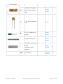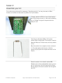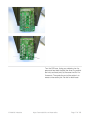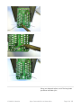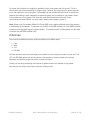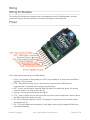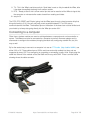
1
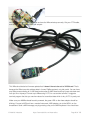
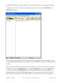
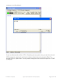
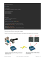
XBee Radios
Created by lady ada
Last updated on 2015-10-31 11:00:18 AM EDT
Guide Contents
Guide Contents
Overview
Simple wireless communication
An XBee wireless modem adapter that doesn't suck!
Reference Pinout
Make it!
2
4
4
5
6
8
Assembling the kit!
8
Preparation
Prepare for takeoff!
9
9
Tutorials
Tools
9
9
Parts list
Bill of Materials
Solder it!
Assemble your kit
Use it!
User Manual
Modules
Which XBee radio module is right for you?
Families
Pro?
Antennas
Wiring
Wiring for Wireless
Pinout
Connecting to a computer
Connect
Connecting, Configuring & Upgrading
Connecting
Configuring with terminal
Configuring with X-CTU
© Adafruit Industries
https://learn.adafruit.com/xbee-radios
13
13
15
15
32
32
33
33
33
34
35
36
36
36
37
41
41
41
46
47
Page 2 of 105
Upgrading with X-CTU
Point2Point
Basic point-to-point communication
BEFORE YOU START!
Setting the network ID
Connecting to Arduino or Boarduino
Arduino link
Wireless Arduino programming/serial link
Step 1. Configure the transmitter
Step 2. Configure the receiver
Step 3. Wire up the receiver
MIDI link
Using XBee to create a wireless bi-directional MIDI link
Introduction
63
72
75
80
80
80
Reinstalling FTDI drivers
Update XBee firmware
Changing XBee to 31250 baud
Build the MidiBee board
Testing
Bonus Trick: Turning the FTDI cable into a MIDI device
Reference
Command reference
81
85
85
87
93
98
101
101
Configuring radios to pass DIO
Changing baud rates
Setting a pin direction
Changing the PAN ID
Changing the Retry Rate
Changing the Packetization Timeout
Resources
More info for your noggin'
Download
XBee v1.1 Adapter files
Software
Datasheets
© Adafruit Industries
51
57
57
57
57
59
63
63
https://learn.adafruit.com/xbee-radios
101
101
102
102
103
103
104
104
105
105
105
105
Page 3 of 105
Overview
Simple wireless communication
© Adafruit Industries
https://learn.adafruit.com/xbee-radios
Page 4 of 105
An XBee wireless modem adapter that doesn't suck!
XBee modems are one of the easiest ways to create a wireless point-to-point or mesh network.
They have error correction, are configured with AT commands, come in multiple flavors and can
create a wireless serial link out of the box! I wanted to make a wireless Arduino project but all the
adapter boards on the market made me unhappy. So I designed what I think is an excellent low-cost
adapter board.
Yes it can act as a breakout board, but it also has...
Onboard 3.3V regulator to cleanly power your XBee, up to 250mA
Level shifting circuitry means that its trivial to connect it to 5V circuitry such as an Arduino
without risk of damage
Two LEDs, one for activity (RSSI), the other for power (Associate)
10-pin 2mm sockets included to protect the modem and allow easy swapping, upgrading or
recycling
All the commonly used pins are brought out along the edge, making it easy to breadboard or
wire up
For use with any XBee/Pro pin-compatible module (check your module datasheet to verify
© Adafruit Industries
https://learn.adafruit.com/xbee-radios
Page 5 of 105
power needs) Works with XBee series 1 and 2!
Specifically created for use with an FTDI cable (http://adafru.it/70) to connect to a computer
via USB. This means that you can use, configure or upgrade the adapter painlessly simply by
plugging in a cable:
Perfect for wirelessly communicating with a microcontroller project.
Reference Pinout
© Adafruit Industries
https://learn.adafruit.com/xbee-radios
Page 6 of 105
The DTR, RTS, RESET and RX pins (going into the XBee) pass through a level converter chip that
brings the levels to 3.3V. You can use pretty much anywhere between 2.7 to 5.5V data to
communicate with the XBee. The breakout pins on the bottom of the board are not level shifted and
you should try to keep data going directly into the XBee pins under 3.3V
© Adafruit Industries
https://learn.adafruit.com/xbee-radios
Page 7 of 105
Make it!
Assembling the kit!
1. Tools and preparation (http://adafru.it/ewO)
2. Check the parts list (http://adafru.it/ewP)
3. Assemble it (http://adafru.it/eei)
© Adafruit Industries
https://learn.adafruit.com/xbee-radios
Page 8 of 105
Preparation
Prepare for takeoff!
Tutorials
Learn how to solder with tons of tutorials! (http://adafru.it/aTk)
Don't forget to learn how to use your multimeter too! (http://adafru.it/aZZ)
Tools
There are a few tools that are required for assembly. None of these tools are included. If you don't
have them, now would be a good time to borrow or purchase them. They are very very handy
whenever assembling/fixing/modifying electronic devices! I provide links to buy them, but of course,
you should get them whereever is most convenient/inexpensive. Many of these parts are available
in a place like Radio Shack or other (higher quality) DIY electronics stores.
Soldering iron
Any entry level 'all-in-one' soldering iron that you
might find at your local hardware store should
work. As with most things in life, you get what you
pay for.
Upgrading to a higher end soldering iron setup, like
the Hakko FX-888D that we stock in our
store (http://adafru.it/1204), will make soldering fun
and easy.
Do not use a "ColdHeat" soldering iron! They are
not suitable for delicate electronics work and can
damage the kit (see here (http://adafru.it/aOo)).
Click here to buy our entry level adjustable 30W
110V soldering iron (http://adafru.it/180).
Click here to upgrade to a Genuine Hakko FX888D adjustable temperature soldering
iron. (http://adafru.it/1204)
© Adafruit Industries
https://learn.adafruit.com/xbee-radios
Page 9 of 105
Solder
You will want rosin core, 60/40 solder. Good solder
is a good thing. Bad solder leads to bridging and
cold solder joints which can be tough to find.
Click here to buy a spool of leaded solder
(recommended for beginners) (http://adafru.it/145).
Click here to buy a spool of lead-free
solder (http://adafru.it/734).
Multimeter
You will need a good quality basic multimeter that
can measure voltage and continuity.
Click here to buy a basic multimeter.
(http://adafru.it/2034)
Click here to buy a top of the line
multimeter. (http://adafru.it/308)
Click here to buy a pocket
multimeter. (http://adafru.it/850)
© Adafruit Industries
https://learn.adafruit.com/xbee-radios
Page 10 of 105
Flush Diagonal Cutters
You will need flush diagonal cutters to trim the
© Adafruit Industries
https://learn.adafruit.com/xbee-radios
Page 11 of 105
wires and leads off of components once you have
soldered them in place.
Click here to buy our favorite
cutters (http://adafru.it/152).
Solder Sucker
Strangely enough, that's the technical term for this
desoldering vacuum tool. Useful in cleaning up
mistakes, every electrical engineer has one of
these on their desk.
Click here to buy a one (http://adafru.it/148).
Helping Third Hand With Magnifier
Not absolutely necessary but will make things go
much much faster, and it will make soldering much
easier.
Pick one up here (http://adafru.it/291).
© Adafruit Industries
https://learn.adafruit.com/xbee-radios
Page 12 of 105
© Adafruit Industries
https://learn.adafruit.com/xbee-radios
Page 13 of 105
Parts list
Bill of Materials
Check to make sure your kit comes with the following parts.Sometimes we make mistakes so double
check everything and email [email protected] if you need replacements!
Please note that an XBee radio module is not included, check the user manual for suggested
modules and distributors.
Image
Name
Description
Part # &
Datasheet
Distributor Qty
IC1
3.3V linear voltage
regulator, 250mA
current
MCP17003302E/TO
Digikey
Mouser
1
IC2
5v compliant buffer chip 74AHC125N
Digikey
Mouser
1
LED1
Red LED
Lite-On LTL-1CHE (or
any 3mm LED)
Digikey
1
LED2
Green LED
Lite-On LTL-1CHG (or
any 3mm LED)
Digikey
1
Digikey
Mouser
2
1/4W 5% 1.0K resistor
R1, R2
© Adafruit Industries
Brown Black Red Gold
https://learn.adafruit.com/xbee-radios
Page 14 of 105
Brown Black Red Gold
Mouser
1/4W 5% 10K resistor
R3
Brown, Black, Orange,
Gold
1
C1
0.1uF ceramic capacitor
(104)
Mouser
1
C2
47uF / 4V capacitor or
greater
Digikey
Mouser
1
Straight male header
Digikey
Mouser
1
Digikey
Mouser
2
Adafruit
Industries
1
10-position 2mm female
header
Sockets for XBee
modem
PCB
© Adafruit Industries
Digikey
Mouser
Circuit board
https://learn.adafruit.com/xbee-radios
Page 15 of 105
Solder it!
Assemble your kit
First, make sure you have all the necessary. Check the parts list. You may also want an XBee
module, as it makes it a little easier to position the 10-pin sockets.
To begin, place the PCB in a vise or third-hand so
that it will be easy to work on. Heat up the soldering
iron to 700degF and get all the parts and tools
ready for use.
First thing we will place is R3, a 10K resistor
(brown, black, orange gold). This resistor is used to
keep the XBee out of reset mode, so that by default
it is on.
Bend the resistor into a staple as shown, and slip it
in. (The stock photo at left shows a 100 ohm
resistor but just ignore the stripes and focus on the
shape.)
Place the resistor in the location marked R3.
Resistors do not have polaritywhich means you can
put it in 'either way' and it will work just fine. Bend
the wire legs out so that the resistor sits flat against
the PCB.
© Adafruit Industries
https://learn.adafruit.com/xbee-radios
Page 16 of 105
Turn the PCB over. Using your soldering iron tip,
press and heat both the pad (the silver ring around
the hole) and lead (wire) at the same time for 2 or
3 seconds. Then poke the end of the solder in to
create a nice solder joint. Do this for both leads.
© Adafruit Industries
https://learn.adafruit.com/xbee-radios
Page 17 of 105
Using your diagonal cutters, cut off the long leads
just above the solder joint.
© Adafruit Industries
https://learn.adafruit.com/xbee-radios
Page 18 of 105
Next are the other 2 resistors, R1 and R2. These
resistor have a different value, 1K. The stripes are
Brown Black RedGold. These resistors set the
brightness of the two indicator LEDs.
© Adafruit Industries
https://learn.adafruit.com/xbee-radios
Page 19 of 105
Solder these two resistors using the same
techniques you learned from the first one.
© Adafruit Industries
https://learn.adafruit.com/xbee-radios
Page 20 of 105
Then, use the clippers to cut the long leads of the
resistors off.
Next are the two LEDs: one LED indicates that the
XBee is up & running ("Asc"), the other indcates
when data is received by the unit ("RSSI") and is
very useful for debugging.
In these examples, the green LED will be the
"Associate Indicator" indicator and the red LED will
be the "Received Signal Strength Indicator."
LEDs are polarized, unlike resistors. This means
they must be soldered in properly in order to
function.The longer lead of the LED is positive and
must go in the hole marked with a +. See the
© Adafruit Industries
https://learn.adafruit.com/xbee-radios
Page 21 of 105
images for a detailed view of how the LEDs are
placed. If they are placed wrong, the LEDs will
simply not light up and it could be very confusing.
© Adafruit Industries
https://learn.adafruit.com/xbee-radios
Page 22 of 105
Once you have doubled checked that the LEDs are
in properly, flip the board over and solder in both
LEDs. Then clip the leads off.
© Adafruit Industries
https://learn.adafruit.com/xbee-radios
Page 23 of 105
The next component we'll place is the large
electrolytic capacitor. This capacitor helps keep the
3.3V power supply stable even when there are
bursts of usage - such as a data transmit!
Electrolytic capacitors are polarized, just like LEDs.
The longer lead indicates the positive leg and
should go into the pad marked + as shown.
If you're using an XBee Pro and you have a
100uF capacitor you have two options, one is to
solder the capacitor close against the PCB so that
you can bend them a little out of the way for the
xbee pro which is a little long. The other option is to
bend them completely at a right angle so that they
are laying 'facedown' on the PCB. The 47uF
capacitor is small enough it doesn't need to be bent
down.
Once the electrolytic capacitor is in place, insert the
3.3V regulator and the smaller ceramic capacitor
as well. The small ceramic capacitor helps filter out
high frequency noise from the power supply and
the regulator turns the 5V input into a nice & steady
3.3V that the XBee requires.
The ceramic capacitor is non-polar, so place it
'either way.'
Then grab the MCP1700-33 regulator. The 3.3V
regulator must be placed correctly, but is easy to
do: simply match the shape on the silkscreen with
the semicircle of the regulator.
If you're using an XBee Pro you have two
options, one is to solder the regulator close
against the PCB so that you can bend it a little out
of the way for the xbee pro which is a little long.
The other option is to bend it completely at a right
angle so that they are laying 'facedown' on the
PCB.
© Adafruit Industries
https://learn.adafruit.com/xbee-radios
Page 24 of 105
Now solder in the power supply components & clip
the leads.
© Adafruit Industries
https://learn.adafruit.com/xbee-radios
Page 25 of 105
Next is the buffer chip. This chip converts the 2V5V signal from the bottom strip of pins to 3.3V so
that you can safely connect the XBee to 5V logic
circuitry. If you're planning to use the two lines of
parallel breakout pins instead of the lines at the
bottom of the PCB, you may want to skip the buffer.
However, most people will want it in place.
The buffer chip must be placed in the right way for
it to work. Look for a U-shaped cutout notch in one
end of the chip. This notch should match the Ushaped notch in the silkscreen. See the picture to
make sure its in right.
Flip over the PCB and solder in every pin of the
buffer carefully. The pins will not have to be clipped
once they are soldered in.
© Adafruit Industries
https://learn.adafruit.com/xbee-radios
Page 26 of 105
Next are the two 10-pin 2mm headers. These
header sockets hold the XBee radio module
securely so that it can be easily replaced or reused.
Put the sockets in the two strips of holes.
If you have a spare XBee module, you can insert
the module into the sockets to keep the spacing
right. Otherwise, keep the headers in place with a
piece of tape.
© Adafruit Industries
https://learn.adafruit.com/xbee-radios
Page 27 of 105
Flip over the board and hold the XBee/headers in
place with one finger to keep them in place.
Then 'tack' the corners of the header with a small
bit of solder, just to keep them in place.
Once they are tacked in place, remove the XBee
module.
When I say Then 'tack' the corners of the header
with a small bit of solder, just to keep them in
place. I mean it! Do NOT use too much solder or
you may accidentally solder the XBee in place. Use
only the minimum necessary!
© Adafruit Industries
https://learn.adafruit.com/xbee-radios
Page 28 of 105
Then go back and solder in each pin of the socket
header.
Do NOT use too much solder or the 2mm headers
© Adafruit Industries
https://learn.adafruit.com/xbee-radios
Page 29 of 105
may 'fill' with solder. Use only the minimum
necessary! If you use too much, use solder wick to
remove some solder
You can now replace the XBee module!
The module is pretty much complete at this point.
You can continue to customize the bottom header
strip or go check out the user manual!
© Adafruit Industries
https://learn.adafruit.com/xbee-radios
Page 30 of 105
You can continue by adding straight header to the
breakout strip at the bottom if you'd like.
Or you can solder the header flat against the back
of the adapter, so that it sticks out along the edge.
© Adafruit Industries
https://learn.adafruit.com/xbee-radios
Page 31 of 105
Another option is to use right-angle header (not
included) and solder it in as shown (or on the
reverse side).
© Adafruit Industries
https://learn.adafruit.com/xbee-radios
Page 32 of 105
© Adafruit Industries
https://learn.adafruit.com/xbee-radios
Page 33 of 105
Use it!
User Manual
Here is a list of topics on how to use the XBee in your project:
1.
2.
3.
4.
5.
6.
Which module to use? (http://adafru.it/jaR)
How to wire the module to your project / computer (http://adafru.it/jaS)
Connecting, configuring and upgrading an XBee (http://adafru.it/jaT)
Setting up point-to-point communication, the simplest wireless link (http://adafru.it/jaU)
Creating a wireless Arduino programming/debugging link (http://adafru.it/jaV)
Reference (http://adafru.it/jaW)
© Adafruit Industries
https://learn.adafruit.com/xbee-radios
Page 34 of 105
Modules
Which XBee radio module is right for you?
There are about half a dozen different XBee modems. It's a good idea to at least review the
differences between them so that you can make sure that you have the right power, range and
network compatibility for your project.
For the examples on the site, I use the XBee 802.15.4 modules. These are low cost ($20),
reasonably low power and are the most popular XBees used by hobbyists for simple wireless
communication.
Families
There are half a dozen 'families' of XBee & it's important to know the differences.
© Adafruit Industries
https://learn.adafruit.com/xbee-radios
Page 35 of 105
Name
Network
Frequency
type
Max
Range
(Pro)
XBee
802.15.4
2.4GHz
point-to- 300' (1
multipoint mile)
XBee
DigiMesh 2.4
2.4GHz
mesh
Notes
most
popular,
cheap
Convertible Distributors,
to...
antenna type
XBee
DigiMesh
2.4
300' (1
mile)
XBee
802.15.4
XBee Pro 900 900 MHz
point-to6 miles
multipoint
XBee
DigiMesh
900
XBee
DigiMesh Pro
900
900 MHz
mesh
6 miles
XBee 900
XBee XSC
Pro
900 MHz
both
15 miles
XBee ZB
2.4 GHz
"Series 2" Pro
XBee ZB
"Series 2"
2.4 GHz
mesh
mesh
long range
ZigBee
400' (1
mile)
Digikey (Wire
$19), Digikey (Chip
$23)
Mouser (Wire
$20), Mouser (Chip
$19)
ZigBee
XBee ZNet
XBP24BZ7CIT-004
XBP24BZ7WIT-004
XBP24BZ7UIT-004
XBP24BZ7SIT-004
XBee ZNet
XB24-Z7CIT-004
XB24-Z7WIT-004
XB24-Z7UIT-004
XB24-Z7SIT-004
The XBee 900 and XBee DigiMesh 900 operate at 900 MHz and so they cannot communicate with
the 2.4 GHz frequency XBees!
The DigiMesh & ZNet 2.5 modules are preconfigured for mesh networking, not point-to-point or
point-to-multipoint connectivity
The XBee 802.15.4 operate at 2.4 GHz but are not compatible with the ZNet/ZB/"series 2" modules!
If you just want to wirelessly send data from one place to another chances are you'll be most happy
with the low cost XBee 802.15.4
Pro?
© Adafruit Industries
https://learn.adafruit.com/xbee-radios
Page 36 of 105
For some of the families, the module is available in both a low-power and Pro version. The Pro
version often has an extra amplifier for longer range. However this means that the power required
to run the modules is also a lot higher! The adapter can be outfitted with either kind of module but
research and testing is often necessary to determine which one is suitable for your needs. Some
Pro modules use a lot of power, The ones that need 265mA should work fine but if your
version/antenna needs 300mA, you may need a better power supply to power it.
Note: Some of the Pro models (XBee Pro S3 and S3B) have a slightly different pinout that requires
a modification to the adapter. In particular, pin 6 which is the RSSI indicator for most XBEE modules
is used as a configuration signal on these models. To use with the S3 or S3B models, you will need
to remove the red RSSI indicator LED.
Antennas
There are three different antenna-options available for the XBee radios:
1.
2.
3.
4.
Chip
Wire
UFL
RP-SMA
The chip and wire antennas are already on the board and don't require any work on your end. The
UFL and RP-SMA options are just connectors, they require an antenna tuned to the correct
frequency and with the proper connector in order to function!
Unless you are doing something that requires a special antenna for directed or high power
transmission, the chip or wire antenna options will be just fine.
© Adafruit Industries
https://learn.adafruit.com/xbee-radios
Page 37 of 105
Wiring
Wiring for Wireless
This section will introduce and explain each of the breakout pins on the XBee adapter. And also
show some ways to wire the board up for use with a computer or microcontroller.
Pinout
This image shows the pinout for the XBee adapter
1. 3V pin - this is either an input power pin (if 5V is not provided) or an output from the 250mA
regulator if 5V is provided
2. DTR - "Data terminal ready" this is a flow control pin used to tell the XBee that the
microcontroller or computer host is ready to communicate.
3. RST - this pin can be used to reset the XBee. By default it is pulled high by the 10K resistor
under the module. To reset, pull this pin low.'
4. Ground - common ground for power and signal
5. CTS - "Clear to Send" this is a flow control pin that can be used to determine if there is data in
the XBee input buffer ready to be read
6. 5V - this is the power input pin into the 3.3V regulator. Provide up to 6V that will be linearly
converted into 3.3V
7. RX - This is the XBee's serial recieve pin. Serial data is sent on this pin into the XBee to be
transmitted wirelessly
© Adafruit Industries
https://learn.adafruit.com/xbee-radios
Page 38 of 105
8. TX - This it the XBee's serial transmit pin. Serial data is sent on this pin out of the XBee, after
it has been transmitted wirelessly from another module
9. RTS - "Ready to Send" this is a flow control pin that can be used to tell the XBee to signal that
the computer or microcontroller needs a break from reading serial data.
10. see pin #1
The DTR, RTS, RESET and RX pins (going into the XBee) pass through a level converter chip that
brings the levels to 3.3V. You can use pretty much anywhere between 2.7 to 5.5V data to
communicate with the XBee. The breakout pins on the bottom of the board are not level shifted and
you should try to keep data going directly into the XBee pin sunder 3.3V
Connecting to a computer
Often times, wireless modules are used as a bridge between a computer and a microcontroller or
sensor. The XBees must also be connected to a computer to perform firmware updates and its
often easier to configure the modules (changing the baud rate, configuring network IDs, etc) this
way as well.
By far the easiest way to connect to a computer is to use an FTDI cable (http://adafru.it/dNN)- use
either 3.3V or 5V. These cables have a USB to serial converter chip molded into them and are
supported by every OS. Thus configuring or upgrading or connecting is really trivial. Simply plug the
cable into the end of the module so that the black wire lines up with GND. There is a white outline
showing where the cable connects.
© Adafruit Industries
https://learn.adafruit.com/xbee-radios
Page 39 of 105
Another method of connecting is using a USB or serial breakout board. Each breakout board is
going to be a little different so check the documentation. Make sure the transmit/receive pins are not
swapped, etc.
© Adafruit Industries
https://learn.adafruit.com/xbee-radios
Page 40 of 105
Finally, it is possible to use a de-chipped Arduino to connect an XBee to a computer. Basically, this
is just using the FTDI chip on the Arduino to pass the serial data. First, gently pry the
microcontroller from its socket using a small flat screwdriver or similar. Try to make sure the pins
don't get bent. Put it in a safe place. Preferably in an anti-static bag.
Then connect the +5V pin on the XBee to the 5V line on the Arduino. Do the same for Ground. The
TX line from the XBee connects to the TX line on the Arduino (because we're replacing the
microcontroller, not talking to it). Same with RX.
If you are planning to try and upgrade the modem - which is pretty common, connect the RTS line to
the right hand solder dot to as shown. That's the best connection you can get to the RTS line. If
you're not upgrading, then you can skip this wire.
© Adafruit Industries
https://learn.adafruit.com/xbee-radios
Page 41 of 105
© Adafruit Industries
https://learn.adafruit.com/xbee-radios
Page 42 of 105
Connect
Connecting, Configuring & Upgrading
Once you have the XBee connected to a computer, you can experiment with connecting, configuring
and upgrading the modules to the latest firmware.
PLEASE NOTE! These instructions are for the Adafruit XBee adapter kit and the Series 1
XBees that are sold in the Adafruit Shop. They may not work for ANY OTHER KIND OF XBEE
OR ADAPTER KIT!
Connecting
First, follow the wiring information in the previous section to connect up the XBee module. Note that
if the module has correct power, the green LED should be blinking. If it isn't, check the wiring and
verify that the XBee is getting power. Some versions or XBees the green LED doesnt blink, but it is
on.
You'll need to figure out which serial port (COM) you are using. Plug in the FTDI cable, USB
adapter, Arduino, etc. Under windows, check the device manager, look for "USB Serial Port"
© Adafruit Industries
https://learn.adafruit.com/xbee-radios
Page 43 of 105
Next you'll need to open up a terminal program. Windows comes with Hyperterminal, so just use
that. It's under Start->Programs->Accessories->Communications->HyperTerminal. If you are
running a different operating system just use whatever terminal program is available for it, such as
ZTerm, minicom, etc. Make sure you understand how those work since a confusion could cause a
big headache.
When you open it up, it should ask you for a new connection. Lets name it "xbee"
© Adafruit Industries
https://learn.adafruit.com/xbee-radios
Page 44 of 105
Next You will select the COM port from the drop down menu, in my case its COM4.
Next, set the properties. Make sure you select 9600 bps, 8 bit, No parity, 1 stop bit and no flow
control. Some programs may call this (9600 8N1). If the XBee has been configured for a different
baud rate, of course, you should use that.
© Adafruit Industries
https://learn.adafruit.com/xbee-radios
Page 45 of 105
You will get a blank screen that says "Connected" in the bottom left corner. Now, change the setup
by selecting File->Properties and then going to the Settings tab and clicking the ASCII Setup
button. Make sure you are sending line ends with line feeds and also echoing local characters.
Now type in +++ (three plus signs) in quick succession. If the XBee is connected up properly you will
get an OK in response.
© Adafruit Industries
https://learn.adafruit.com/xbee-radios
Page 46 of 105
If you got an OK that means the XBee is powered and wired up correctly! If its not working, check:
Try again, be sure to wait 10 seconds between each attempt at typing in +++ and type the +'s
quickly
Is the module powered? Green LED should be blinking
Are RX & TX swapped?
Do you have the correct baud rate? By default it should be 9600 baud 8N1 no hardware
handshake but if it has been used for something else the baud rate might be different.
© Adafruit Industries
https://learn.adafruit.com/xbee-radios
Page 47 of 105
Next try typing in +++ (receive OK) and then AT and press return to get another OK This is basically
how we can configure the XBee, by sending it AT commands (they all start with AT for ATtention).
After a while, the XBee times out of configuration mode and goes back to pass-through connection
mode. So if you want to get back to config mode, just type in +++ and it will start responding again.
Configuring with terminal
XBee's can be configured directly using a terminal program, or via a program such as Digi's XCTU
program - which is specifically designed to make configuration easy.
For example, here are two examples of how configure the module's baud rate.
Using a terminal, you can change the baud rate using the ATBD command with a number
afterwards that selects which baud rate to use:
0
1
2
3
4
5
6
7
= 1200
= 2400
= 4800
= 9600
= 19200
= 38400
= 57600
= 115200
-> +++ (get into AT mode)
© Adafruit Industries
https://learn.adafruit.com/xbee-radios
Page 48 of 105
-> AT (check if xbee modem is responding)
OK
-> ATBD (get current baud rate as above)
3 (9600)
-> ATBD 4 (set baud rate to 19200)
OK
-> ATBD (check again)
4
-> ATWR (write the baud rate change to flash)
OK
Then reset the module, either by pulling the reset pin low for a second or removing power
(unplugging cable, etc) To connect now, set the terminal to use 19200 baud, otherwise the module
will not respond! You can set it back to 9600 baud by giving it the command ATBD 3 and
thenATWRiting it to the flash.
Configuring with X-CTU
Digi/Maxstream wrote a little program to help configure XBees, it's also the only way I know of to
upgrade them to the latest firmware. Unfortunately it only runs on Windows.
After installing and starting the program, select the COM port (COM4 here) and baud rate (9600 is
default). No flow control, 8N1
© Adafruit Industries
https://learn.adafruit.com/xbee-radios
Page 49 of 105
To verify, click Test / Query
© Adafruit Industries
https://learn.adafruit.com/xbee-radios
Page 50 of 105
Hopefully the test will succeed. If you are having problems: check that the XBee is powered, wired
correctly, the right COM port & baud rate is selected, etc.
The test will respond with the firmware version. Now we will change the baud rate for the modem
using X-CTU.
Go to the Modem Configuration tab. This is where the modem is configured and updated.
Click on Modem Parameters -> "Read" to read in the current version and settings.
© Adafruit Industries
https://learn.adafruit.com/xbee-radios
Page 51 of 105
You may want to skip ahead and upgrade the modem now, since it can be confusing if you don't
have the latest firmware on it.
Scroll down in the settings pane until you find the Serial Interfacing -> Interface Data Rate setting.
Click on the setting and select 4 for 19200 baud.
© Adafruit Industries
https://learn.adafruit.com/xbee-radios
Page 52 of 105
Once that is selected, click on Write to program that setting in place. Don't forget to 'reboot' the
module by power-cycling it or pulling the Reset pin low. Next time you want to connect, make sure to
change the COM port setup to 19200 or you wont be able to talk to the module!
Upgrading with X-CTU
There's a good chance your XBee is not running the latest firmware & there's a lot of features
added, so next up is upgrading!
Go to the Modem Configuration tab. This is where the modem is configured and updated.
© Adafruit Industries
https://learn.adafruit.com/xbee-radios
Page 53 of 105
Click Download new versions... and select to download the latest firmwares from the Web.
© Adafruit Industries
https://learn.adafruit.com/xbee-radios
Page 54 of 105
Once you have downloaded the newest firmware, it's time to upgrade!
Click on Modem Parameters -> "Read" to read in the current version and settings.
© Adafruit Industries
https://learn.adafruit.com/xbee-radios
Page 55 of 105
Now you will know for sure what function set, version and settings are stored in the modem.
Select from the Version dropdown the latest version available.
© Adafruit Industries
https://learn.adafruit.com/xbee-radios
Page 56 of 105
Check the Always update firmware checkbox.
And click Write to initialize and program the new firmware in!
© Adafruit Industries
https://learn.adafruit.com/xbee-radios
Page 57 of 105
That's it, now you have the most recent firmware for your modem. You should now uncheck the
Always update firmware checkbox. If you have problems, like for example timing out or not being
able to communicate, make sure the RTS pin is wired up correctly as this pin is necessary for
upgrading. FTDI cables are already set up for this so you shouldn't have a problem.
Once you update the firmware, any configuration changes you've made such as Baud Rate
adjustment will be thrown away.
© Adafruit Industries
https://learn.adafruit.com/xbee-radios
Page 58 of 105
Point2Point
Basic point-to-point communication
The most basic way to communicate using the XBee modems is point to point. That means one
modem communicating with another modem. Serial data goes in one XBee, is transmitted
wirelessly, and goes out the other & vice versa.
If you just want a wireless link - between two microcontrollers, computers, Arduinos, etc. then start
here!
PLEASE NOTE! These instructions are for the Adafruit XBee adapter kit and the Series 1
XBees that are sold in the Adafruit Shop. XBee series 2 are slightly different and these
instructions may not work exactly as shown. Check the Series 2 datasheet for differences!
BEFORE YOU START!
Make sure to READ the modem parameters/firmware before starting, so you don't accidentally
overwrite something - especially if you're doing a bunch of modules at once!
Setting the network ID
For this simple network, we want two modems to talk only to each other. That means that if you're in
a school, lab or workshop other people's XBee's can interact with yours causing some major
confusion.
A good way to avoid this is to set the network ID (otherwise known as the PAN - Personal Area
Nework - ID) to a unique value. By default all XBee's use PAN ID #3332. The ID is 4 bytes of
hexadecimal and can range from 0000 to FFFF
Changing the PAN is easy. If you want to do it with X-CTU simply select a new ID and Write it to the
module.
© Adafruit Industries
https://learn.adafruit.com/xbee-radios
Page 59 of 105
If you are using a terminal to connect, use the ATID command to set and check the PAN ID
-> AT (check if xbee modem is responding)
<- OK
-> ATID (get current PAN)
<- 3332 (default, or something else)
-> ATID 3137 (set new id)
<- OK
-> ATID (check again)
<- 3137
-> ATWR (write the change to flash)
<- OK
© Adafruit Industries
https://learn.adafruit.com/xbee-radios
Page 60 of 105
Connecting to Arduino or Boarduino
Let's set up an example where the computer is going to talk to a microcontroller project such as an
Arduino or Boarduino. If you're using a different microcontroller or communicating between two
microcontrollers, it's going to be pretty similar.
Start by first setting up the PAN ID and baud rate for the two modems. For this example I will
assume that they are set up for the default baud rate of 9600
Conncet one module to your microcontroller. First connect +5V and Ground to provide power. Make
sure the XBee's green LED is blinking. Next connect the RX line (input) of the XBee to the TX line
(output) of the microcontroller and vice versa. For the Arduino/Boarduino below I will be using a
"Software Serial" program and use pin #2 as the RX and pin #3 as the TX. This allows me to use the
default hardware USB serial port without conflicting. (For example, I can still upload a sketch.)
© Adafruit Industries
https://learn.adafruit.com/xbee-radios
Page 61 of 105
© Adafruit Industries
https://learn.adafruit.com/xbee-radios
Page 62 of 105
Now connect the other module to a computer using an FTDI cable or similar. (http://adafru.it/jaS)
Open up a terminal to the computer's XBee and start typing into it - whatever you want. You should
see the red LED on the other modem light up, indicating data is being received. If you don't see the
red LED light up, check that you have compatible modules (http://adafru.it/jaR), matching baud rates
and PAN IDs.
Now install the NewSoftSerial library (http://adafru.it/exi)& upload the following sketch:
© Adafruit Industries
https://learn.adafruit.com/xbee-radios
Page 63 of 105
#include <NewSoftSerial.h>
NewSoftSerial mySerial = NewSoftSerial(2, 3);
void setup() {
pinMode(13, OUTPUT);
Serial.begin(9600);
Serial.println("Goodnight moon!");
// set the data rate for the SoftwareSerial port
mySerial.begin(9600);
mySerial.println("Hello, world?");
}
void loop()
{
// run over and over again
if (mySerial.available()) {
Serial.print((char)mySerial.read());
}
if (Serial.available()) {
mySerial.print((char)Serial.read());
}
delay(100);
}
This will set up a point-to-point 'tunnel' between the two XBees. What is typed into the terminal at
the computer will end up in the Arduino's Serial Monitor. Try it out!
© Adafruit Industries
https://learn.adafruit.com/xbee-radios
Page 64 of 105
Arduino link
Wireless Arduino programming/serial link
If you have an Arduino project where the dev board is stuck inside a machine, or attached to the
rafters or is inaccessable in some other way, a wireless programming/debugging link will save you
tons of time. This tutorial is an extension on Rob's version (http://adafru.it/ewQ). In this tutorial, no
extra firmware or hardware (other than a capacitor) is necessary. Just use the default bootloader. I
use a 'classic' Arduino but of course this can be easily adapted to any version or clone.
You will need 2 XBee adapter kits (http://adafru.it/126), 2 matching-protocol XBee
modules (http://adafru.it/ewR), an FTDI cable (http://adafru.it/70) (or other FTDI breakout board, if
you can wire it up correctly) as well as a 0.1uF ceramic capacitor, 10Kohm resistor and NPN
transistor. The resistor and capacitor can vary quite a bit if you don't have exact values.
PLEASE NOTE! These instructions are for the Adafruit XBee adapter kit and the Series 1
XBees that are sold in the Adafruit Shop. XBee series 2 are slightly different and these
instructions may not work exactly as shown. Check the Series 2 datasheet for differences!
This tutorial currently only works for Arduinos with Duemilanove bootloaders. If you have an UNO,
you can either reprogram the chip with a Duemilanove bootloader via the IDE or purchase a chip
and swap it in (http://adafru.it/123).
Step 1. Configure the transmitter
© Adafruit Industries
https://learn.adafruit.com/xbee-radios
Page 65 of 105
One XBee will act as the 'reset transmitter', it will be attached to the computer via an FTDI cable and
wireless send programming commands to the receiver. Let's set this one up first.
Connect up the transmitter adapter with XBee modem to your computer using the FTDI cable.
And start X-CTU, just like on the configure (http://adafru.it/jaT) page.
© Adafruit Industries
https://learn.adafruit.com/xbee-radios
Page 66 of 105
Once you've connected/tested that you can communicate with the modem, go to the configure tab
and read in the current setup.
Then set the following:
The PAN ID should be some 4 digit hex number that will only be used by these two modems - to
prevent confusion.
© Adafruit Industries
https://learn.adafruit.com/xbee-radios
Page 67 of 105
Set the baud rate to 19200 if you're using an Arduino with a 168 chip or older '328p chip. You can
check your Arduino documentation to figure out which baud rate to use.
Or 57600 if you're using a more recent Arduino with '328p chip.
© Adafruit Industries
https://learn.adafruit.com/xbee-radios
Page 68 of 105
Next we'll set the Packetization Timeout. This is what determines how long to wait before sending
the characters over. We're doing some 'bulk transfer' when sending 10K programs over, so you'll
probably want this number high like 10.
Set pin D3 to be a digital input.
And set the Digital IO change detect to FF. Technically you can set it to 0x08, which is the mask to
listen for only D3 but this certainly works fine.
© Adafruit Industries
https://learn.adafruit.com/xbee-radios
Page 69 of 105
Now the transmitter is set up to send the current status of pin D3 to any listening modems.
Now solder in a tiny jumper between the RTS pin and D3. This will tie the status of D3 to the status
of the RTS pin which is can be configured to be used as the 'arduino reset pin'
© Adafruit Industries
https://learn.adafruit.com/xbee-radios
Page 70 of 105
Finally setup the FTDI cable so that the RTS pin will reset the Arduino. For Mac/Linux it will already
be done but if you're using Windows you'll need to make a slight change to the driver preferences.
In the Device Manager, select the USB COM port.
© Adafruit Industries
https://learn.adafruit.com/xbee-radios
Page 71 of 105
Then right click and select Properties
© Adafruit Industries
https://learn.adafruit.com/xbee-radios
Page 72 of 105
Click on the Port Settings tab, and click on Advanced...
© Adafruit Industries
https://learn.adafruit.com/xbee-radios
Page 73 of 105
Make sure Set RTS On Close is selected. Click OK.
Step 2. Configure the receiver
Now we will set up the other XBee so that it will listen to changes on pin D3. Connect it to the FTDI
cable and read in the current configuration just like the first one.
The PAN ID should match the transmitter's
© Adafruit Industries
https://learn.adafruit.com/xbee-radios
Page 74 of 105
Set the baud rate to 19200 or 57600 to match the transmitter, again.
OR
Next we'll set the Packetization Timeout. This is what determines how long to wait before sending
© Adafruit Industries
https://learn.adafruit.com/xbee-radios
Page 75 of 105
the characters over. We're doing some 'bulk transfer' when sending 10K programs over, so you'll
probably want this number high like 10.
Set pin D3 to be a digital output, default high.
Set the I/O Output to Disabled. This will prevent the receiver from displaying the status update in the
serial line and instead just toggle the matching pin.
© Adafruit Industries
https://learn.adafruit.com/xbee-radios
Page 76 of 105
Finally, set I/O line passing input address to FFFF. If you set up unique addresses for the receiver
and transmitter xbees, of course you should change this to match but FFFF will match all
addresses.
Now write the changes to the receiver XBee.
Step 3. Wire up the receiver
The transmitter XBee connects directly to the FTDI cable/computer and the receiver is wired to the
target Arduino. Here I use a half-sized breadboard and rubber band since not much space is
necessary. Solder a wire from pin D3 on the receiver XBee adapter, so that you can plug it into the
breadboard. This is the mirrored reset line from the transmitter Xbee.
© Adafruit Industries
https://learn.adafruit.com/xbee-radios
Page 77 of 105
Xbee's are pretty weak and don't have the oomph to reset an Arduino on their own, so we need to
wire it up to a transistor which will do the heavy lifting of pulling the reset line down. Pretty much any
small NPN transistor will work just fine here. Put a 0.01uF to 0.1uF capacitor in series with the wire
from the XBee, and connect the other side to the NPN transistor base. The emitter of the transistor
connects to ground. Put a resistor around 10K between the base and emitter. This will pull down the
base to keep the Arduino from resetting accidentally.
© Adafruit Industries
https://learn.adafruit.com/xbee-radios
Page 78 of 105
The collector then goes the Arduino's reset line. Make sure the grounds are all connected, and that
the XBee is wired from the Arduino's 5V line.
© Adafruit Industries
https://learn.adafruit.com/xbee-radios
Page 79 of 105
Now power the Arduino either through the USB cable or from a DC supply. That's it! Now you can
reprogram it and also watch the serial monitor from more than 100 feet away. Don't forget the serial
monitor -must- be at the same baud rate as programming because the XBees can only talk at their
configured baud rate.You can also use AVRdude 'out of the box' which I prefer because you get a
nice little progress bar. Simply go to the directory where your sketch is stored and look for the .hex
file in the applet subfolder.
© Adafruit Industries
https://learn.adafruit.com/xbee-radios
Page 80 of 105
© Adafruit Industries
https://learn.adafruit.com/xbee-radios
Page 81 of 105
MIDI link
Using XBee to create a wireless bi-directional MIDI link
Introduction
If you have a modern musical instrument, there's a good chance it has a MIDI port. MIDI is an
ancient serial protocol that runs at 31.25Kbs, often they come in pairs an Input and Output. Setting
up MIDI gear usually requires lots of cabling, tying inputs to outputs across a studio or stage. In this
XBee tutorial we'll show how to configure the XBee to talk at the MIDI baud rate, and then how to
create a bi-directional wireless MIDI link.
Good for hooking up Processing/PureData/Max to a MIDI device.
For simplicity sake, I will assume you have a Windows machine. I assume that serial port baudrate
aliasing can be done on Mac's and Linux but, well, I'll do it later!
You'll want to study the this great MIDI specification (http://adafru.it/ex2) website with full MIDI
protocol details so that when I say "Note on/off message" you know its a 3-byte packet of data and
what each byte is made of!
In case you are wondering, the flight delay time is 6.0 milliseconds with default settings. By setting
the packetization timeout to 1 instead of 3, the delay time goes down to 5.5ms
PLEASE NOTE! These instructions are for the Adafruit XBee adapter kit and the Series 1
XBees that are sold in the Adafruit Shop. They may not work for ANY OTHER KIND OF XBEE
© Adafruit Industries
https://learn.adafruit.com/xbee-radios
Page 82 of 105
OR ADAPTER KIT!
Reinstalling FTDI drivers
This first part is pretty much a 'must' no matter what you're planning to do. We have to configure the
XBee(s) to talk at 31,250 baud. That means we need to be able to talk to the XBee at that baud rate
in order to configure it, say with our handy FTDI cable. Now unfortunately this isn't a default baud
rate under Windows (a major oversight, it seems). Instead we have to do a little trick called baud
rate aliasing where the driver is running at 31,250 but the computer thinks it's talking at 38,400
baud, a default baud rate. Note that this is very dumb but hey, that's Windows.
Unplug your FTDI cable and any FTDI devices like arduinos, USB-serial converters, GPS's, and the
like.
Download FTClean (http://adafru.it/eaV), the driver-cleaner utility from FTDI. Uncompress and run
FTClean.exe
Click the three windows to verify that you Really Want To Do This. The computer will hang for a few
seconds while the drivers are uninstalled. It'll then look like this
© Adafruit Industries
https://learn.adafruit.com/xbee-radios
Page 83 of 105
Now you're ready to -reinstall- the FTDI driver that aliases 38,400 baud to 31,250 baud.
You can download the edited driver here (http://adafru.it/ex3) note that it's called the MIDIfied driver.
Uncompress it onto the Desktop.
Now plug in your FTDI cable again. The Windows driver detection window will pop up.
© Adafruit Industries
https://learn.adafruit.com/xbee-radios
Page 84 of 105
Select No, not this time and click Next
Select Install from a list or specific location (Advanced) and click Next
© Adafruit Industries
https://learn.adafruit.com/xbee-radios
Page 85 of 105
Select Search for best driver in these locations. Then uncheck Search removable media and
check Include this location in the search: then click Browse and navigate to the uncompressed
MIDIfied FTDI driver folder. Click Next
If it complains about Windows Logo testing, click Continue Anyways
© Adafruit Industries
https://learn.adafruit.com/xbee-radios
Page 86 of 105
OK! You may have to do this again, since there seems to be two parts of the driver. Just repeat,
making sure to install the MIDIfied FTDI driver.
Update XBee firmware
If you haven't updated your XBee's firmware, you should do that now (http://adafru.it/ex4).
Remember that you are still going to connect to the XBee at 9600 baud cause it's fresh-outta-thebox.
Changing XBee to 31250 baud
Now comes the magic. We're going to connect to the fresh XBee at 9600 through a terminal (I'm
going to use the terminal built into XCTU but of course any terminal program is OK).
Then we're going to set the baud rate to a special value. By default the XBee can talk on the
standard rates, like 2400, 9600, 57600, etc. However it is possible to make it talk a special rate by
passing the hexidecimal value to ATBD. For example, if you want 31250 baud, convert that number
to hex -> 7A12. Set the XBee by giving it the command ATBD7A12. Then check again to verify its
7A12! Finally, write it to flash with ATWR.
Note that once you write it to flash you can only talk to the XBee at that baud rate so you must be
sure that you have the MIDIfied FTDI drivers installed because otherwise you won't be able to
communicate with the XBee anymore!
© Adafruit Industries
https://learn.adafruit.com/xbee-radios
Page 87 of 105
OK now you have set the XBee to 31250 communication. You can hard reset the XBee by
un/replugging the adapter. Test that you did things right by trying to connect to the XBee again, now
at 31250. Remember that you have to select 38400 as the connection baud rate because that is
aliased to 31250.
© Adafruit Industries
https://learn.adafruit.com/xbee-radios
Page 88 of 105
Build the MidiBee board
Label your MIDI XBee cause you'll need to keep track of it. Now it's time to build the hardware to
connect DIN-5 MIDI jacks to the XBee.
Adafruit XBee Adapter
XBee module
Series 1 either 'standard' or 'pro
© Adafruit Industries
https://learn.adafruit.com/xbee-radios
Adafruit
1
Adafruit
1
Page 89 of 105
MIDI connector
CUI SDS-50J
MIDI Optocoupler
6N138
220 ohm resistor 5% 1/4W
Red - Red - Brown - Gold
CMOS Hex inverter
74HC04N
Digikey
Mouser
2
Digikey
Mouser
1
Digikey
Mouser
4
Mouser
Digikey
1
You'll also need a source of ~5V. I suggest a 4AA battery holder. And something to build it on. I'm
using a half-sized solderless breadboard.
We'll be building this, click for a larger version.
© Adafruit Industries
https://learn.adafruit.com/xbee-radios
Page 90 of 105
Note that a big chunk of it is on the XBee adapter. MIDI isn't that voltage sensitive (it uses current
not voltage) so the 5V supply doesn't need to be precise. It can vary a bit which is why using 4 AA's
(varies from 4.8V to 6V) and it's just fine.
We'll start by inserting the first jack into pins 30B
29C 28B 27C and 26B. It goes into the end of the
breadboard. The little teeth in front should go into
the blue - rail, you may have to twist it a little but it
should snap in place.
The other jack goes into pins 30J 29I 28J 27I and
26J. The two front teeth go into the blue - rail as
well.
© Adafruit Industries
https://learn.adafruit.com/xbee-radios
Page 91 of 105
Place the 6N138 optocoupler chip. This is what
allows us to interface with the current-mode MIDI
protocol. Pin 1 of the 6N138 goes into pin 19E
Then place the 74HC04 hex inverter. This chip
takes the weak output of the XBee TX pin and
buffers it so that it can drive the 5-10mA needed for
the MIDI current loop. Pin 1 of the 74HC04 goes
into pin 11E
Start laying down power lines. Connect the VCC
pins of the 74HC04 and 6N138 using red wire to
© Adafruit Industries
https://learn.adafruit.com/xbee-radios
Page 92 of 105
the red rail. Connect the ground pins using black
wire to the blue rail. Connect the middle pin of the
MIDI jack to ground as well.
Connect the MIDI in jack to the optocoupler:
breadboard pin 25 connects to row 21. Breadboard
row connects to a 220ohm resistor that then
connects to row 20 as shown. This completes the
current loop for MIDI data coming in.
Now we will do the MIDI out current loop. Row 25
connects to the red rail via a 220ohm resistor. Pin 6
(row 21) connects to the red rail as well, through
another 220ohm resistor.
© Adafruit Industries
https://learn.adafruit.com/xbee-radios
Page 93 of 105
Now well add the buffer. Row 29 connects to pin 10
of the 74HC04 (row 15) through a 220ohm resistor.
Make a wire jumper between row 13 and 14.
Finally we will get the wires ready for the XBee
adapter. Connect Row 4 to the blue ground rail on
both sides. Connect row 6 to the red power rail.
Now we have the ground rails tied together and the
XBee connected to power.
Next we will connect the MIDI in data. Connect a
wire from pin 6 of the 6n138 (long yellow wire) to
row 7 right next to the red power wire.
Connect another wire from 74HC04's pin 13 (row
12) using a green wire to row 8, right next to the
yellow wire.
Get the 4xAA battery holder setup. Solder the red
and black wires to a double-header. This will make
it easy to plug into the breadboard. I used some
heatshrink to keep the two from touching. It's
easier if you place the header in the breadboard
while soldering.
© Adafruit Industries
https://learn.adafruit.com/xbee-radios
Page 94 of 105
Your adapter should be all ready to go!
Connect the battery pack so that the red wire is
attached to the red power rail and the black wire is
attached to the blue ground rail. Marking the MIDI
jacks with 'in' and 'out' stickers will help keep them
apart.
To keep the board attached to the battery pack,
use a rubberband or hotglue. You can also peel the
backing off the breadboard and stick it right on.
© Adafruit Industries
https://learn.adafruit.com/xbee-radios
Page 95 of 105
Testing
We'll do a simple test to make sure that we have the XBee wired up correctly. Get your FTDI cable,
and connect it to your other XBee and adapter.
This XBee should also be firmware updated but it doesn't have to be set to 31250 baud! That's
because the XBee transmits wireless data in its own ZigBee protocol, not plain serial. You can have
one XBee communicating at 31,250 baud and another at 9600 baud and they'll pass data back and
forth just fine. Anyways. Connect up to XBee using X-CTU or use another terminal. I suggest a
terminal program that lets you see hex values for transmitted data which is why X-CTU is pretty rad.
Make sure your MidiBee bread board is powered, the green LED on the xbee adapter should be
blinking. Connect a MIDI out from a musical instrument, MIDI adapter, etc to the MIDI in on the
breadboard. Send a MIDI message, say by pressing a key on the MIDI keyboard. You should see
© Adafruit Industries
https://learn.adafruit.com/xbee-radios
Page 96 of 105
the RSSI (red) LED on the XBee connected to your computer light up as it is receiving a message!
If you look in your Terminal, you'll see the MIDI messages show up. These are NOTE ON and
NOTE OFF messages.
Don't forget, you should connect to the computer-XBee at whatever baud rate that XBee is set to. If
it's still at factory-default 9600, connect at 9600. If you also 'MIDIfied' it, connect at 38400 (aliased to
31250).
Now it's time to test sending MIDI data out via the XBee. You can use X-CTU terminal to connect to
the XBee and click on Assemble Packet. Then select HEX display/entry and type in 90 32 64 this
is a note on message. Click Send Data. You should see the RSSI (red) LED on the MidiBee
breadboard light up indicating it received the packet. If you connect a synth to the MIDI out it will
play a note (well, assuming it's set to MIDI address 0, you should craft the Note On message as
© Adafruit Industries
https://learn.adafruit.com/xbee-radios
Page 97 of 105
necessary to set the address).
If you use software such as Max or PD or Processing (or even python, etc), you can also now send
MIDI messages by opening the serial port at whatever baud rate you've set up the XBee. For
example, here is a quick sketch. You may need to change the name of the Serial port from "COM3"
to whatever.
© Adafruit Industries
https://learn.adafruit.com/xbee-radios
Page 98 of 105
import processing.serial.*;
Serial myPort;
// A little helper
void sendMIDI(int command, int data1, int data2)
{
myPort.write(command);
myPort.write(data1);
myPort.write(data2);
}
void setup() {
// List all the available serial ports:
println(Serial.list());
myPort = new Serial(this, "COM3", 9600);
// Send a Note On message, then a Note Off message
sendMIDI(0x90, 0x32, 0x64);
// D note on, 64 velocity
delay(1000); // one second
sendMIDI(0x80, 0x32, 0x64);
// D note off, 64 velocity
}
Check that your MIDI synth is getting the messages.
Sweet! You now have a wireless MIDI setup for sending and receiving data from any computer!
© Adafruit Industries
https://learn.adafruit.com/xbee-radios
Page 99 of 105
Bonus Trick: Turning the FTDI cable into a MIDI device
OK sure you can send messages to your MIDI device via the serial port. But there's an awful lot of
programs that are going to require that you use a real MIDI device. What now? Well luckily, the nice
fellows at KORG have designed a Windows driver that turns a COM port into a proper MIDI device!
You can download it here (http://adafru.it/ex5), it's called Midi Driver PCIF-NT for Windows
NT/2000/XP it seems to not work with Vista, sorry.
Follow the instructions in the MANUAL.HTM file included in the zip file.
© Adafruit Industries
https://learn.adafruit.com/xbee-radios
Page 100 of 105
Make sure the FTDI cable is set to COM2, 3 or 4 because the driver can't cope with higher
numbers. You can set the FTDI cable's COM port in the Device Manager. Set the KORG driver to
the correct COM port.
Now you should have the KORG MIDI driver device in the Device Manager.
Now you can use somthing like MIDIOX (or any other program that can talk to MIDI ports) to
communicate with the XBee/MIDI link.
© Adafruit Industries
https://learn.adafruit.com/xbee-radios
Page 101 of 105
© Adafruit Industries
https://learn.adafruit.com/xbee-radios
Page 102 of 105
Reference
Command reference
Configuring radios to pass DIO
This is how to set up two radios so that pin signals (high or low) from one radio will be passed to the
other.
In this instance, we will show how to set up sending from to another, but having bi-directional
communication should be similar.
On the transmitter radio:
1. Under I/O Settings, set the pins that will be transmitted to "3 - DI" (data in)
2. Set IC - DIO to FF (this will make it look at all the pins and transmit when they change)
3. Set sample rate to 0 (unless you want synchronous updates)
On the receiver radio:
1. Set the corresponding pins to "4 - DO (LOW)" or "5- DO (HIGH)"
2. Under I/O Line Passing set "Input Addresses" to 0xFFFF (allow any radios)
3. Set IU - I/O Output enable to Disabled
Changing baud rates
You can change the baud rate using the ATBD command:
0
1
2
3
4
5
6
7
= 1200
= 2400
= 4800
= 9600
= 19200
= 38400
= 57600
= 115200
-> AT (check if xbee modem is responding)
<- OK
-> ATBD (get current baud rate as above)
<- 3 (9600)
-> ATBD 4 (set baud rate to 19200)
<- OK
-> ATBD (check again)
<- 4
-> ATWR (write the baud rate change to flash)
<- OK
© Adafruit Industries
https://learn.adafruit.com/xbee-radios
Page 103 of 105
Setting a pin direction
Use ATDx where x is the pin number from 0 to 8
0 = Disabled
1 = Special purpose: CTS pin (pin D7 only!) RTS pin (pin D6 only!) Association Indicator (pin
D5 only!)
2 = Analog input (pins 0 thru 5 only)
3 = Digital input
4 = Digital output, default is low (0)
5 = Digital output, default is high (1)
For example to set pin D4 to be a digital input
-> AT (check if xbee modem is responding)
<- OK
-> ATD4 (get current pin state)
<- 0 (disabled)
-> ATD4 3 (set pin to digital input)
<- OK
-> ATD4 (check again)
<- 3
-> ATWR (write the change to flash)
<- OK
Changing the PAN ID
By default all XBee's use PAN ID #3332. The ID is 4 bytes of hexadecimal and can range from 0000
to FFFF. XBees will only send/receive data to other modems on the same PAN.
Use ATID #### where #### is the 4 digit hex ID
For example to set the PAN ID to 3137
-> AT (check if xbee modem is responding)
<- OK
-> ATID (get current PAN)
<- 3332 (default, or something else)
-> ATID 3137 (set new id)
<- OK
-> ATID (check again)
<- 3137
-> ATWR (write the change to flash)
<- OK
© Adafruit Industries
https://learn.adafruit.com/xbee-radios
Page 104 of 105
Changing the Retry Rate
Use ATRR to change the rate from 0 to 6 (default is 0). A higher retry rate such as 6 will provide a
more 'rugged' connection but if you prefer to drop packets as long to get better response, set this to
0
Changing the Packetization Timeout
Use ATRO to change the rate from 0 to FF (255 in hex) the default is 3. The PT sets how long to
wait before sending serial characters in a wireless packet. If you are sending lots of data, use a
higher timeout to make sure theres more sent in each packet. If you're not sending a lot of data and
want better response rate, set it to 0.
© Adafruit Industries
Last Updated: 2015-10-31 11:00:20 AM EDT
Page 105 of 105
Resources
More info for your noggin'
Datasheets, specs & more from Digi (http://adafru.it/ewY)
Tom Igoe's XBee page (http://adafru.it/ex8)
Rob Faludi's XBee page (http://adafru.it/ex9)
Download
XBee v1.1 Adapter files
These files are released under CC 2.5 Attribution/Share alike. Enjoy!
Schematic (http://adafru.it/ewT) (PNG)
Schematic (http://adafru.it/ewU) & Layout (http://adafru.it/ewV) in EagleCAD format
Software
Digi/MaxStream's X-CTU configuration & update software page (http://adafru.it/ewW)
FTDI Windows driver v2.0.0 (http://adafru.it/ewX) (not the newest, which seems to have some
fixed 'bug' or feature
Datasheets
Datasheets for the XBee modems can be downloaded from the Digi page (http://adafru.it/ewY).
Select which modem you are interested in for more info.