1
Setting up N1MM logger
with the microham MK2R+
N1MM logger Version: 7.11.0
microHAM Router Version: 5.03
Last update: November 22, 2007
Copyright 2007, Thomas Tinge (PA1M)
Table of Contents
1 General information (setting up microHAM and N1MM logger)....................................................1
1.1 General information.............................................................................................................1
1.1.1 Firmware updates and router versions.......................................................................1
1.1.2 Router software..........................................................................................................1
1.1.3 Info on the web (used in this guide)...........................................................................1
1.2 MK2R+ ................................................................................................................................2
1.2.1 Proposed Virtual Port numbers..................................................................................2
1.3 N1MM logger.......................................................................................................................5
1.3.1 "PTT line" (usually RTS) on a serial port....................................................................5
1.4 Station Master information...................................................................................................5
1.5 microKEYER (discontinued)................................................................................................6
1.6 Elecraft K3...........................................................................................................................6
1.7 Icom radios..........................................................................................................................7
1.8 Kenwood radios...................................................................................................................7
1.9 All other Radios...................................................................................................................7
1.10 Realtek sound card drivers and MK2R+'s USB Voice CODEC.........................................8
1.10.1 One soundcards installed (only Realtek)..................................................................8
1.10.2 Ok I have the realtek problem..................................................................................9
1.10.3 Ok I have more than 3 mixers..................................................................................9
1.10.4 Two soundcards installed (disable Realtek and use the other..)............................10
2 PA1M − MK2R+ and N1MM logger setup.......................................................................................11
2.1 Radio settings....................................................................................................................11
2.2 microHAM Router setup....................................................................................................12
2.3 N1MM logger setup...........................................................................................................20
2.4 MMTTY setup....................................................................................................................25
2.5 PC setup............................................................................................................................28
3 PA1T − MK2R+ and N1MM logger setup........................................................................................29
3.1 Radio settings....................................................................................................................29
3.2 microHAM Router setup....................................................................................................30
3.3 N1MM logger setup...........................................................................................................38
3.4 MMTTY setup....................................................................................................................43
3.5 PC setup............................................................................................................................46
4 N1MM − RTTY operation / settings................................................................................................48
4.1 MMTTY setup....................................................................................................................48
4.1.1 Configure it to use the EU1SA profile.......................................................................48
4.2 N1MM logger − RTTY − Operating the contest.................................................................49
4.3 QSO making tips with N1MM logger..................................................................................49
4.3.1 Using Hover mode:...................................................................................................49
4.3.2 The rate improver − Right Click = Enter not menu"..................................................49
4.4 Do you have... (what to check when it does not work)......................................................50
4.5 How to setup RTTY (by Rich VE3KI)...............................................................................50
4.6 Best exchange format........................................................................................................51
4.7 Welcome to RTTY Contesting...........................................................................................52
4.8 Starting in September........................................................................................................53
i
1 General information (setting up microHAM and
N1MM logger)
In this document information is gathered about setting up the freeware contest program N1MM logger
with the microHAM MK2R+ SO2R controller and Station Master banddecoder.
The original text from Joe, W4TV has been used as a start for this document and updated with texts
from Pete, N4ZR his SO2R−only document. Also information from the N1MM and microHAM reflector
are used and of course own trial and error.
This document has multiple sections. The information decribed is being used at the stations PA1T
(Timon) and PA1M (Thomas). Choices have been made depending on the equipment used at these
stations (PC, Radios etc). As an example: My PC has only 1 serial port so there is room for 7 virtual
ports in uRouter in combination with N1MM logger. The shack PC at PA1T has 3 serial ports, so only
5 virtual ports are left to use and the LPT port is used.
Id like to thank all who have written about the MK2R+ in combination with N1MM logger. Especially
Id like to thank Joe, W4TV and Pete, N4ZR for all information they have put on the web, reflectors
and in personal e−mail to us. Thanks to Tom, N1MM for adding the microHam protocol to N1MM
logger.
This information is placed on the web in the hope that it may help others in setting up the microHAM
MK2R+ SO2R controller. The setup below is working for us but might not work at your place. The
MK2R+ is a very complex hardware/software combination as it can be set up in so many different
ways.
73 Thomas
PA1M
1.1 General information
1.1.1 Firmware updates and router versions
It is neccesary to have loaded the CORRECT firmware version for each version of Router. Each
Router install file includes a firmware file. However, Router will only prompt for to load firmware if the
installed version is OLD (reverting is not expected). Comparing the change logs for Router and the
firmware for the MK2R, Router 7.1.5 requires firmware 4.2 Whenever firmware is changed, new
"Power−up settings" must be saved to the interface (except USB II) and power must be cycled in
order to properly initialize the controller in the interface. The firmware gets loaded to the interface −
leaving the file on the computer does no good. Having a mismatch between firmware and Router will
almost guarantee problems with PTT and switching.
Router tells the firmware of the MK2R at the bottom of the router Screen. Just before the Winkey rev.
1.1.2 Router software
The exe file (download) is the same for update or fresh install.
1.1.3 Info on the web (used in this guide)
Everything necessary to configure MK2R+ is in the manual:
http://www.microham.com/Downloads/MK2R_English_Manual.pdf
the same for the Station Master, a manual at:
http://www.microham.com/Downloads/SM_English_Manual.pdf
Support information from Joe : http://www.microham−usa.com/support.html
The MK2R+ setup Guide for N1MM (with LPT control):
http://www.microham.com/Downloads/MK2R_N1MM_Setup.pdf
and Pete's guide (with microHAM Protocol/USB control):
http://groups.yahoo.com/groups/N1MMLogger/files/USB−only%20SO2R.pd
13−2−2009
1 General information (setting up microHAM and N1MM logger)
1
1.2 MK2R+
1.2.1 Proposed Virtual Port numbers
Note: The absolute port numbers do not matter. The key is consistency − the same port number must
be used for a specific function every time it is used. The port numbers below will be used (as
proposed by Joe, W4TV).
COM 3 − WinKeyer
(it is best to assign WinKey to the lowest port to avoid loss of CW if another port is activated for CW)
COM 4 − Radio #1
(PTT and Footswitch is optional on this port)
COM 5 − Radio #2
(PTT and Footswitch is optional on this port)
COM 6 − Digital #1
FSK and PTT for Radio #1 (assign Radio 1)
COM 7 − Digital #2
FSK and PTT for Radio #2 (assign Radio 2)
COM 8 − MK2R
Protocol port
The porposed ports below are used at PA1M where PA1T does not have COM 3 and also uses the
LPT port.
Ouch it's not working − please check
a.. Confirm that you have selected the correct soundcard for audio in N1MM and microHAM Router.
b.. Confirm that you have selected the correct wave file path in N1MM Logger.
c.. Confirm that you have the correct audio connections between microKEYER and the soundcard (all
three cables).
d.. Double−check the preamp setting (jumpers) in the microKEYER (enabled for dynamic mic,
bypassed for electret mic).
e.. Confirm that any wave files are being played back on the left channel of the soundcard
(microKEYER uses left only).
a.. For debugging purposes it is very convenient to connect a set of powered computer speakers in
parallel with the soundcard "Line Out" (microKEYER SOUNDCARD OUT jack).
b.. If you hear the proper audio but it doesn't reach the radio, the issue is in microKEYER's audio
switching ...
c.. if you do not hear the right audio the issue is in the software (N1MM Logger or Windows).
d.. Refer to the Set−up Guide for microKEYER and N1MM Logger for Router configuration
information and the N1MM Logger manual for N1MM configuration information.
e.. microKEYER/N1MM Set−up Guide is available through the "Download Documents" link in Router's
"Help" menu.
Q. Where are the MK2R settings stored
A. Using Router version 5 and up: C:\Documents and Settings\All Users\Application
Data\microHAM\cfg\
Q. How to set up WYH on the MK2R
A. When WYH is selected it simply switches the headphone feed to the USB Audio CODEC
andrecords 'what you hear'. The audio settings selected by the RECORDING/DIGITAL LEFT/RIGHT
controls are ignored. WYH is designed to be able to record 'what you hear'.
WYH is headphone audio and will be effected by the radio volume control.
Q. How to setup SSB
What kind of microphone are you using and how is it connected? You MUST set the jumpers correctly
on the Live mic preamp based on the type of microphone and you must configure the soundcards
correctly in Router.
If you can play a wave file via USB Voice CODEC, the CODEC driver is installed (it is built into
Windows and not a microHAM driver). However, N1MM Logger REQUIRES that the Audio Settings
tab (in N1MM Logger) is set up properly to select the correct inputs.
Further, if your computer has a motherboard soundcard that uses the RealTek HD audio chipset (or
an add−in soundcard by SoundMax with the RealTek HD audio chipset), N1MM Logger will often
13−2−2009
1 General information (setting up microHAM and N1MM logger)
2
select the wrong input unless USB Voice CODEC is the Windows Default sound device (bad idea)
because of issues with the non−standard RealTek driver.
Finally, MK2R+ MUST be in VOICE mode and the audio switching must be correct so that the
microphone is switched to the sound card when you are recording ... there are three possibilities
depending on whether you are trying to record on air or not and whether the logger activates PTT.
MK2R+ audio switching should be CmCmA or CmCmCm and you should not press the PTT while
recording. Radio(s) must be in SSB mode and Router must know that (black box around the VOICE
switching configuration).
Q. My TX audio is not working anymore
Uninstalling and reinstalling Router will not change a thing with the CODECs. You are wasting your
time.
Confirm that the microphone is connected correctly, the proper microphone input (front or back)
selected, the correct CODEC assigned to the Voice and Digital/Recording sides of Router, and the
proper CODEC assigned in the audio switching.
It is very easy to overlook the subtle difference between Voice and Audio CODEC in both the Audio
Switching tab and the Audio Mixer tab.
I would also confirm that Windows has not done something strange like install another audio device,
or change the order in which the CODECs are installed. Click on the Get ID buttons and be sure that
Wave IN ID = Wave Out ID = Mixer ID. Confirm that the "Soundcard name in the "Get ID" box is the
one you expect (that it matches the selected soundcard).
Q. TX Mic pull down does not offer "microphone" as a selection option. My laptop only has
only mic in and line out.
A. If the TX Mic select box on Router does not offer a microphone chose, the sound card does not
support echoing the microphone to the speaker/headphone output and you will not be able to route
the microphone through the laptop sound card or change DVK messages "on the fly."
You will still be able to record and playback messages with the N1MM Logger DVK but you will not be
able to record while doing so. Configure your audio switching for ACA ... this connects the mic directly
to the radio "at rest" and when the hand mic or footswitch is pressed and connects the DVK
output to the radio when the computer PTT is active. When recording a wave file, do not press the
hand mic PTT or footswitch.
Q. I couldn't find an "Apply" button or similar.
A. If you make a change, the change is applied immediately. If you want to save that change to the
preset, use "Preset | Save As" to update (over write) the existing preset.
Note, you will probably want to set the VOICE/DIGITAL box on the Audio Switching TAB to "Use
Voice Settings" for this weekend. Since TenTec does not include an AFSK mode in their radios/CAT
command set, Router must determine Voice/Digital mode by operating frequency. By default
operation between 7030 and 7045 is considered to be "DIGITAL" (AFSK).
Be sure to UNCHECK the "Mute mic on supported radios" box on the N1MM Logger Configurer
"Other" tab. N1MM expects to run DVK via the AUX connector on the Orion. MK2R uses the mic
input.
Q. How can I record SSB− and/or CW−QSOs in N1MM with SO2R/1R−configuration and
MK2R+?
A. On CW, you can do it by selecting the USB Audio CODEC in N1MM's configurer|Audio tab. On
SSB you have to choose between the N1MM DVK and recording, because the Audio tab in the
configurer does not allow you to set a different soundcard for recording and DVK purposes
Q. Function keys in SSB: Should I use the N1MM−DVK or the MK2R+ − DVK? Which is better?
A. I would use the N1MM DVK because it allows for full integration between N1MM functions and the
DVK, and use a separate recording application.
Q. Which sound card driver to select in Windows
A. Windows automatically selects any newly installed audio device as the default device for Sound
Playback and Sound recording. This is undesirable as Windows Sounds would be played through
MK2R+ and onto the air!
13−2−2009
1 General information (setting up microHAM and N1MM logger)
3
For Windows 2000 or Windows XP. right click on the Speaker Icon on the task bar and select "Adjust
Audio Properties" or open "Sounds and Audio Devices" in Control Panel and reset the Default device
for Sound Playback and Sound Recording to your computer's primary sound device.
For Windows Vista, right click on the Speaker Icon on the task bar and select "Playback Devices or
open Sounds in Control Panel and reset the Default Playback device to your computer's primary
sound device.
Q. I'm missing some virtual serial ports, can't select them, can;t create them
A. First try to delete all virtual ports from within router and create them again.
If this does not help remove all virtual ports from within Windows (System from within the
Configuration screen), after deleting all ports they will be automatically created again (and hopefully
also the lost ones). It worked here..
Q. Do I have the Realtek sound card driver problem?
A. Select "microHAM CODEC" in the Audio Mixer tab and click, "Get ID". If Wave IN ID <> Wave Out
ID <> Mixer ID (ie. they do not have all the same number) you have the "Realtek problem" where the
application is using the Mixer ID instead of the WAVE IN ID to select audio input.
Q. Using CAT and 2nd CAT ports
A. As two programs CAN NOT under any circumstances look at the same port simultaneously. That is
the reason for the CAT and 2nd CAT ports in Router ... the primary logging/control program looks at
the CAT port to control the radio and the secondary program (e.g., CW Skimmer, Spectravue,
PowerSDR, etc.) looks at the 2nd CAT port for Icom "transceive" broadcasts, Kenwood IF data or
slow speed (< 500 msec) polling with older Yaesu rigs to get the operating frequency for
synchronization.
Q. Where are router's settings and presets stored?
Router's settings and presets are stored in the Windows registry. The stored settings are updated
when Router is closed. Any "registry protection" or "registry backup/restore" program will prevent
saving the settings (by restoring the previous state). In addition, if Router does not close properly, the
settings will not be saved.
Q. How works the virtual serial ports
A. The Eltima virtual serial port is a software interface e.g., it provides software equivalents to the
various buffers and registers of an 8250 compatible UART − for OEM specific hardware and software.
For Router, the Eltima VSP code provides an interface compatible with the Microsoft Communications
Toolbox. The data to/from the foreign applications is transferred to Router which reformats it into a
microHAM proprietary multiplexed data stream (Radio_1 CAT, Radio_2 CAT, Control − which
includes the various PTT, Footswitch, audio routing, and PC generated CW flags − and WinKey
channels) and sends it via a DLL interface at 230Kbps through the USB port and the FTDI UART in
the interface to the microcontroller in the specific interface.
The microcontroller then demultiplexes the data and distributes it to the appropriate process in the
controller. CAT and WinKey data is put in standard ASCII form and handled by UARTS in the
controller. The various control flags are acted on by the firmware to generate the necessary internal or
external controls.
If Router and the microHAM interface are not running, the VSP should either not exist (Router not
running) or return an error (interface not running).
Virtual ports created and defined by Router can only be used to communicate with or control devices
that are attached to a microHAM interface. Just as with a "real" port, only one program at a time may
open a virtual serial port and no two ports (virtual or real) may have the same address (COM
number).
Q. MK2R+ and Vista
MK2R+ works with Vista. However, since Vista no longer allows an application (Router) to control the
audio endpoints, it is more difficult to set−up. In effect, the user needs to use the Vista Volume Mixer
to select each device/endpoint and set the level of that endpoint for each individual application (e.g.,
separate settings for Writelog, N1MM, WinTest, DX4Win, MMTTY, DXLab Suite, etc.).
Q. Reset MK2R/Microkeyer/Digikeyer settings
13−2−2009
1 General information (setting up microHAM and N1MM logger)
4
Save Power up settings to reinitialize the EEPROM in microKEYER, close Router to save the settings
and then restart Router.
FSK or CW messages
PTT ON/OFF is not supported as an embedded command in the MK2R. Use the F10 key from the
PS/2 keyboard.
RF problems with my MK2R
The bypass modification for the microKEYER II has not been evaluated for the MK2R+. However, due
to the layout it will not be as simple as the microKEYER II version. Circuit grounds for the USB "core"
and the balance of MK2R+ are separated and there is no conveniently located place for field
installable bypasses.
1.3 N1MM logger
1.3.1 "PTT line" (usually RTS) on a serial port
One note with regard to N1MM Logger (and other logging/control software) ... DigiKeyer and other
microHAM interfaces responds to the "PTT line" (usually RTS) on a serial port. The interfaces do not
respond to "PTT via command."
In using N1MM with microHAM Router, it is best to set the PTT delay in N1MM slightly longer than the
PTT Lead (microKEYER, microKEYER II, MK2R/MK2R+) or PTT Delay (DigiKeyer) parameter.
N1MM Logger will begin producing audio (AFSK or Voice macro) when its delay time expires. If
Router's PTT Lead/PTT Delay is longer, the transceiver will not have switched before
N1MM Logger starts generating audio. A good starting point is to set N1MM Logger PTT delay to 20
msec and Router's PTT Delay to 10 msec. If the particular configuration does not require a delay for
receive antenna switching (LNA PTT) and the logging/control program provides its own PTT delay
(like N1MM), it is even possible to set Router's PTT delay to zero (0).
Always uncheck "PTT via command" when using microHAM Router. If "PTT via Command" is used,
the PA PTT and/or LNA PTT outputs on the microHAM interface are not usable because Router and
the keyer have no way of knowing that N1MM Logger has commanded the radio to begin transmitting.
The PTT delay setting in N1MM Logger and the PTT lead or PTT delay settings in microHAM Router
should be adjusted for the particular installation. The PTT Lean/PTT Delay setting in Router should be
less than the PTT delay in the logging program. Router's PTT Delay will control the delay between PA
PTT/LNA PTT activation and the activation of the transceiver PTT. The logger PTT will control the
delay between activation of PA PTT/LNA PTT and the start of RF.
If the PA relay was very slow one might set PTT delay in N1MM Logger at 40 mSec and set PTT
Lead/Delay in Router at 30 mSec. In that case PA PTT would activate as soon as the operator
pressed an F−key while the radio PTT would activate 30 mSec later and RF (audio/CW) would start
10 mSec after the transceiver PTT. With hand mic PTT, the amplifier would still receive its PTT
command 30 mSec before the transceiver to allow time for the (slow) relay to switch and settle.
1.4 Station Master information
Quick Guide
• Connect iLink cables between MK2R and Station Master
• Check the "iLINK Couple" (frequency source) setting in Ports tab Station Master.
• On SM: Go to MENU mode (push MENU button for more than 1 second and Select *** CAT
*** (SM will follow radio)
Relays Station Master (Rotator interface)
All of the relays in Station Master are Forward model N4100HS3DC12. The specification on the case
says: 3A/125VAC/30VDC.
Although the Tailtwister is specified at 2.25A operating, remember that the starting surge will be
13−2−2009
1 General information (setting up microHAM and N1MM logger)
5
higher and there will be a substantial voltage "kick" on when the relays. The relays in the Station
Master won't handle the currents required by the Tailtwister, so it was necessary to use some SPDT
power relays with 20A contacts and 12V coils that I obtained at a local electronics surplus outlet to
buffer the Station Master relays. The power relay NO contacts were simply wired across the CW,
CCW and Brake switches in the Tailtwister control box. The SM Analog Input was taken directly from
Terminal 3 of the control box and the Analog Ground was wired directly to Terminal 1 of the box.
Randy, W8FN
Trap alarms
Extend the "Report time" setting on the "Display" tab to the maximum and make "Alarm" the only
Report selection for the bottom line.
Errors
KEY IN TOO LONG − Key IN can be found in Router on PA & Sequencer subtab from Antenna
Switching& PTT sequencer in Station Master
Cahange the setting or deselect when not used. Dont forget to Store this information to the Station
Master...
Antenna lock out between Station Masters.... NO
With two Station Master controllers, one unit does not know which antennas are selected by the other
controller. There is no provision for sharing rotors between the units − but the firmware/software
continues to evolve.
Resource sharing
Networked resource sharing of rotors, SteppIR antennas, etc. are features planned for Station Master
Deluxe.
Rotor control
With the present software, rotor control is tied to selection of an antenna on the rotor. There are two
"solutions" − first use a separate RS−232 interfaces rotor controller with the "auxiliary" port or second
define all antennas as being on the rotor.
Antenna rotor resources are not shared among multiple Station Master controllers. The rotor control,
SteppIR control and amplifier control are bound to the Station Master and transceiver to which it is
connected. Antennas are shared using a Double Ten Switch with each Station Master controlling one
"side" or set of outputs.
Stack switch
Station Master can interface with a stack switch by defining each configuration as a separate antenna.
However, if you do that you will need to design an external relay network to switch the stack switch
control lines between the two Station Master controllers so that the "active" Station Master is
controlling the stack switch.
1.5 microKEYER (discontinued)
Audio connections
microKEYER
computer
Soundcard OUT Line Out
Soundcard IN
Line IN
Soundcard Mic
Mic IN
1.6 Elecraft K3
13−2−2009
1 General information (setting up microHAM and N1MM logger)
6
No audio on line in
CAT noise : Buzzing sort of doo doot sound in the background of the record
This is CAT polling noise. The K3 has RF chokes in the ground leads of the RS−232 port, the ACC
port and the mic return. This results in common mode noise if the ground ring of the Foster mic
connector is not tight and the KIO3 board is not seated properly. The polling noise is particularly
significant if the rear panel (3.2mm) mic input is used because there is NO chassis ground on that
jack other than through the RF choke.
Check all your grounds! With the K3 it will help to add jumpers between the ground/common pins of
the DB9 (RS−232 − pin 5), DB15HD (ACC − pins 5 & 12) and Foster (Mic − pins 7 and 8) connectors
and the shell of the connector. This allows the "ground" currents to reach the chassis directly rather
than see approximately 4 Ohms in the common leads.
1.7 Icom radios
CAT noise
With CAT noise in the Icom transceivers, check the ground connection on the "Remote" jack in the
transceiver and on the shell of the "Remote" plug of the transceiver interface cable. There have been
several reports in which the ground trace on the CAT (remote) has been opened. If the CAT return is
open, CAT data will return through the ground lead of the ACC jack and can effect the "line" input
which seems to be always on in Icom radios except the IC−7800.
1.8 Kenwood radios
No audio on SSB
With Kenwood radios you need to be aware of operating frequency and the "Digital Band Map." If the
"Voice/Digital" box is set to "by frequency," audio and PTT settings will be set to either the Voice or
FSK/Digital settings based on the operating frequency (Digital Band Map). In addition, most Kenwood
transceivers require PTT_2 on digital (ACC jack audio input) and PTT_1 for Voice (Mic connector).
Audio Routing C and A are appropriate with PTT_1. Audio Routing B generally requires PTT_2 which
mutes the microphone.
1.9 All other Radios
CAT noise
The cat data reports are also more common among those users with non−Icom (dynamic)
13−2−2009
1 General information (setting up microHAM and N1MM logger)
7
microphones as they generally run much higher "mic gain" levels which increases sensitivity at the
line in.
1.10 Realtek sound card drivers and MK2R+'s USB Voice CODEC
1.10.1 One soundcards installed (only Realtek)
This screenshot file explains how to get around a problem caused by some Realtek sound card
drivers (used for Realtek and some Soundmax cards and onboard audio components) when trying to
use the MK2R+'s USB Voice CODEC. I know this sounds nuts (after all, the MK2R+ uses its own
sound cards, right?), but bear with me.
Certain sound cards and motherboard sound card components made by Realtek and Soundmax
(which uses the Realtek drivers) prevent proper operation of features such as on−the−fly recording of
DVK messages. There's a lot of magic here about ID numbers and such, but instead of getting into
that, here are some easy step−by−step screenshots to get you going.
If you have this problem, the usual symptom is that N1MM will record an empty file when you try to
record with Ctrl+Shift+Fx.
First, in N1MM logger, go to the Audio tab in Config|Ports,other
Select the USB Voice CODEC as the Device. The only inputs it has are Microphone. Don't worry
about the Radio Input Port − N1MM can't currently record QSOs with the Audio CODEC anyhow. Just
set it up like this.
Now open Windows Control Panel, and select the Sounds and Audio Devices tab.
13−2−2009
1 General information (setting up microHAM and N1MM logger)
8
Click on the Audio tab first. Set the USB Voice CODEC as the Default device for BOTH playback and
Recording, and click Apply, then OK out. Now click the Sounds tab.
Normally, the Sound scheme will be identified as Windows Default, but if you leave it alone, the
Windows sounds (like the File not found "clunk", for example) may wind up in your recordings or even
go out over the air. To prevent that, you need to create a new scheme. Starting from the Windows
default scheme you select each sound in turn from the Program events list, and assign "None" to it.
Then save the resulting scheme under the No Sounds title. Apply it and OK out.
Now go back into the Router, and make sure that the Audio Switching tab has CmCmCm set for
Voice, and that the left channel is selected for radio 1.
That's all there is to it. Now when you record DVK messages on the fly (by pressing Ctrl+Shift+Fx),
your microphone audio will reach the Voice CODEC, and playback will work normally as well.
Probably the best place to monitor your voice level is on the Audio Mixer tab of Router, in the
left−hand bargraph. It has much more "resolution" than the simple indicator provided in the Info
window of N1MM Logger. Enjoy!
73, Pete N4ZR
1.10.2 Ok I have the realtek problem
Depending on the software you are using to record the mic audio, Wave In ID <> Wave Out ID can be
a real problem. You have set the default recording device to the microHAM CODEC and the default
playback device to something else. The Mixer is still somewhereelse and most amateur software can
not handle that condition.
1.10.3 Ok I have more than 3 mixers
The Windows XP mixer (SoundRec32.exe) only accepts mixers 0−3 on the command line (the way
Router calls the TX or RX mixer). When you have at least four soundcards (five Mixers) in your
system and microHAM CODEC is the fourth or fifth mixer, it can not becalled directly with the TX
Mixer or RX Mixer button.
13−2−2009
1 General information (setting up microHAM and N1MM logger)
9
1.10.4 Two soundcards installed (disable Realtek and use the other..)
The issue with the RealTek HD Audio system is that RealTek creates two separate mixers: RealTek
HD Audio Input and RealTek HD Audio Output.
Windows assigns the Audio Output as Mixer 0 (Windows Default) and Audio Input as Mixer 1. This
results in a mismatch between the Wave In ID, Wave Out ID and Mixer ID for not only other
soundcards but also the Wave Out device. For example a system with RealTek HD on the
motherboard, Sound−Blaster Audigy 2 ZS, microHAM microKEYER II and microHAM MK2R+ looks
like this under Windows XP (my own "testbed" system):
ID Wave Out Wave In Mixer
−−−−−−−−−−−−−−−−−−−−−−−−−−−−−−−−−−−−−−−−−−−−−−−−−−−−−−−−−−
0 RealTek HD Out RealTek HD In RealTek HD output
1 SB Audigy 2 ZS Audigy 2 ZS RealTek HD input
2 USB Voice CODEC USB Voice CODEC Audigy 2 ZS
3 microHAM CODEC microHAM CODEC USB Voice CODEC
4 USB Audio CODEC USB Audio CODEC microHAM CODEC
5 n/a n/a USB Audio CODEC
It is possible to force "normal" behavior by defining the desired soundcard as the Windows Default
(with all the issues of "Windows sounds" impacting the radio and other software screwing with the
audio settings). However, with a RealTek sound device installed, the HD Input Mixer will almost
always take up the "Mixer ID 1" position and every device other than the default will be impacted by
the Wave/Mixer mismatch.
N1MM Logger addresses the Wave In and Wave Out devices based on the Mixer ID. In the system
documented above, setting N1MM Logger to use the microHAM microKEYER II (microHAM CODEC)
results in an attempt to use the output and input devices attached to the "USB Audio CODEC" (the
digital/recording input of microHAM MK2R+). Attempting to "cheat" by telling N1MM Logger to use
"USB Voice CODEC" also fails because USB Voice CODEC has no "Line" input.
WriteLog will function in this environment because it addresses all of the systems inputs and outputs
individually rather than through the mixer.
So when having two sound cards (Realtek onmotherboard) disable the Realtek in the motherboard
BIOS. Use the other soundacrd installed and make it the "Windows
Default." You can then allow Windows to access the default card without impacting "microHAM
CODEC" and N1MM Logger should not have any problems selecting inputs since the Mixer ID will
point to the correct end−points. This is exactly what I would do to prepare my test system for daily use
(I leave the ReaTek enabled for testing/evaluation).
This situation is not restricted to systems with RealTek hardware. It sometimes occurs with old
modems that support telephone answering/recording capabilities; they often install just an audio
output but rely on the soundcard fortheir input. The Mixer/Wave mismatch also occurs in systems
where the user has installed a USB Audio output only device like some of the digital audio playback
"dongles." Those devices install output mixers but no input mixer.
73, ... Joe Subich, W4TV
13−2−2009
1 General information (setting up microHAM and N1MM logger)
10
2 PA1M − MK2R+ and N1MM logger setup
NB. This setup is not maintained anymore since beginning 2008.
This setup is for personal use at the stations PA1M and put on the web so we have this information at
hand wherever we are.
With the Station Master and Elecraft K3 a new setup has started and can be found here.
Back to menu.
Setup Mk2R+ at little pistol station PA1M (Thomas).
Station information PA1M
Port info
Radio 1
Kenwood TS−2000
Radio 2
Com 1 Real
Free
None (sold)
PACC contest: Kenwood TS−850S
Com 2 Virtual
Free
None
Com 3 Virtual
Free
ICE−419A (2)
Com 4 Virtual
MK2R −
Radio 1
microHam DOUBLE TEN switch
Com 5 Virtual
MK2R −
Radio 2
few
Com 6 Virtual
MK2R −
PTT 1
−
Com 7 Virtual
MK2R −
PTT 2
N1MM logger
Com 8 Virtual
MK2R −
WinKeyer
Banddecoders
Bandfilters
Antenna switch
Used for
Antenna's
Website
Contest logger
Pentium−IV − 3 Ghz
1 GB memory
PC shack
PC real serial ports
1
Vitual serial ports
7
PC LPT ports used
0
Realtek soundcard
problem
No
Router Version
LPT 1
Real
Free
5.0.3
N1MM logger version
6.x
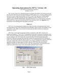
2.1 Radio settings
Proposed settings by microHAM:
Kenwood TS−2000
Elecraft K3
Turn OFF internal CW keyer in the radio
Menu nr.39 = INVERS
Menu nr.50B = 5
Menu nr.50C = 9
Menu nr.50D = 9
Turn OFF internal CW keyer in the radio
13−2−2009
2 PA1M − MK2R+ and N1MM logger setup
11
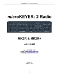
2.2 microHAM Router setup
Tab: Ports
• Radio: Assign Radio 1 to COM4 and Radio 2 to COM5
♦ Click the Set button for each radio and select the radio on that port from the drop
down box.
◊ Uncheck?? the Disable router queries box.
♦ Test: Check the radio by turning the VFO, frequency in uRouter should follow
frequency radio.
• FSK: Assign ports for FSK. DI−1 to COM6 and DI−2 to COM7 and uncheck the PTT box.
♦ NB. If you are not using N1MM Logger for RTTY contesting you can skip this step.
♦ If you are using the same port for PTT and FSK, uncheck the PTT box next to FSK.
♦ Further down set PTT to the same port as FSK and select RTS.
♦ Test: Test buttons sends FSK (MK2R: PTT: green; CW/FSK blinks green)
• 2nd FSK: Not used
• CW: Not used
• PTT: Assign PTT Radio 1 to COM6 and PTT Radio 2 to COM7 and select RTS for both
ports.
• 2nd PTT: Not used
• Foot switch: Not used. Is output port to software, not supported by N1MM logger.
• Winkeyer 2: Assign COM3. Check Generate PTT1 on the CW/WinKey tab if you do not
intend to operate QSK.
♦ Test: Test buttons sends test in CW on radio 1 (MK2R: PTT: green; CW/FSK red in
CW rhythm)
• Control: Assign COM 8
13−2−2009
2 PA1M − MK2R+ and N1MM logger setup
12
Tab: Audio Switching
Radio 1 − TS−2000
CW: AAA (always)
VOICE: CmCmCm (mic in
MK2R+)
CmCmA (mic in
soundcard)
FSK/DIGITAL: ?????
VOICE/DIGITAL: Select by
frequency
Use line out channel: Left
Radio 2 − TS−850
CW: AAA (always)
VOICE: CmCmCm (mic in
MK2R+)
CmCmA (mic in
soundcard)
FSK/DIGITAL: ?????
Use line out channel: Right
If you do not intend to use N1MM DVK, use ACmA. Radio 1:
Radio 2:
13−2−2009
2 PA1M − MK2R+ and N1MM logger setup
13
Tab: Audio Mixer
Rules for audio playback are: Click on "get ID" in router's audio mixer tab. Make sure that
WAVE IN ID == WAVE OUT ID == MIXER ID. The N1MM Logger audio control cannot handle the
situation where the Wave ID <> Mixer ID − it will send (or record as the case may be) audio from the
wrong sound card. If the Wave and Mixer IDs are not the same,set the MicroHAM CODEC as the
windows "default" sound card and confige N1MM Logger to use the default device.
The soundcard name displayed in the audio mixer selection box (left half of the Mixer tab in
MK2R/MK2R+) must match that shown in "Get ID" and the "Select Device" selection box in the
N1MM Logger Audio tab.
13−2−2009
2 PA1M − MK2R+ and N1MM logger setup
14
Tab: PTT
Radio 1
Radio 2
CW: PTT1 (microphone jack)
VOICE: PTT1 (microphone jack)
FSK/DIGITAL: PTT2 (rear panel jack)
CW: PTT1 (microphone jack)
VOICE: PTT1 (microphone jack)
FSK/DIGITAL: PTT2 (rear panel jack)
PA PTT: Select
LNA PTT: unselect
PA PTT: Select
LNA PTT: unselect
For CW/VOICE select PTT1 (microphone jack) and for FSK/DIGITAL PTT2 (rear panel jack).
If you are using QSK in CW select QSK for CW. PTT tail????
13−2−2009
2 PA1M − MK2R+ and N1MM logger setup
15
Tab: CW/Winkey
Paddle mode: Iambic B (Accu keyer)
Swap paddles: select
No changes needed as all other settings under control by N1MM logger.
13−2−2009
2 PA1M − MK2R+ and N1MM logger setup
16
Tab: CW messages
Not in use as the function keys in N1MM logger control the CW messages.
Test: test CW by pressing the Test button.
Tab: FSK messages
Not in use as the function keys in N1MM logger control the FSK messages.
Tab: DVK
Not in use as the function keys in N1MM logger control the Voice messages.
Tab: Keyboard
Not in use (sorry we don't have one..).
Tab: SO2R
Select microHAM control protocol on COM port (NB com port is set on Ports tab) and 1 footswitch
for both radios.
TX logic: First one wins???
These settings allow N1MM Logger to fully control both transmit and receive selection automatically.
Stereo receive is commanded by the ` (backquote or unshifted tilde key) or the {STEREOON} and
{STEREOOFF} macros.
13−2−2009
2 PA1M − MK2R+ and N1MM logger setup
17
Tab: ACC
13−2−2009
2 PA1M − MK2R+ and N1MM logger setup
18
Select Controlled by microHAM control protocol in the two drop−down boxes. Pins 6−9 and
10−13 are connected to two banddecoders which drive the microHAM 2by10 SO2R switch. Note that
these precisely pass through the antenna selections from the N1MM Logger Antenna tab − so you
can have multiple antennas on a given band, selectable from the keyboard.
Tab: Functions
13−2−2009
2 PA1M − MK2R+ and N1MM logger setup
19
By Pete, N4ZR: I wanted to be able to use N1MMs FocusOther function to control where the entry
focus was when I was transmitting on one radio or the other. The greyed−out options for Computer
TX on R1 and R2 get in the way of that. If you uncheck Latch in the Headphone Switching area,
that disables those choices and lets N1MM be the boss.
Manual TX on R1/2: the ability to listen to sidetone when sending paddle CW = to hear sidetone in
both ears when sending manually.
Saving you work
Save settings to a preset by selecting menu Preset | Save as. Choose a position and name it:
N1MM−all modes.
Note: Each of the tabs is complex enough to warrant careful attention. Incidentally, it is always a good
idea to save your last working setup as a Preset, so that you can retrieve the situation if you mess up.
It also makes sense to save your experiments.
2.3 N1MM logger setup
Theres nothing magical about which ports are used for which purposes; you just have to be
consistent between N1MM Logger and the MicroHam Router.
• Click Config| Configure Ports, Telnet Addresses, Other ...
• Hardware Tab
PA1M Hardware Tab
3 = Winkey 4−6:No CW/Other 5−7: Digital + PTT + No CW! (CW = 3)
13−2−2009
2 PA1M − MK2R+ and N1MM logger setup
20
13−2−2009
COM 3
COM 4
Winkey port
Radio 1: Settings Kenwood
TS−2000
COM 5
COM 6
2 PA1M − MK2R+ and N1MM logger setup
21
Radio 2: Settings Kenwood
TS−2000
Radio 1: PTT + footswitch Always
On????
COM 7
COM 8
Radio 2: PTT + footswitch Always
On????
MK2R+ control port
• Digital
Modes Tab
♦ Select Soundcard as the TU Type
♦ Select FSK as the mode.
♦ Enter the path to each MMTTY installation.
13−2−2009
2 PA1M − MK2R+ and N1MM logger setup
22
• Winkey
Tab
♦ Use 2nd Output should be checked (?????????)
♦ Pin 5 Function should be PTT (unless you are using QSK)
13−2−2009
2 PA1M − MK2R+ and N1MM logger setup
23
• Mode
Tab
♦ Contest specific choices
♦ SSB/CW operation
◊ Mode recorded in log
⋅ ??????
◊ Mode sent to radio
⋅ Follow mode recorded in log
⋅ Log mode/Radio mode: ??????
♦ RTTY operation
◊ Mode recorded in log
⋅ Always: RTTY
◊ Mode sent to radio
⋅ Follow mode recorded in log
⋅ Log mode/Radio mode: RTTY to LSB
• Audio
Tab
♦ 2 − Single Card − Two Radio, No Sound Card SO2R
◊ Select Device is: USB Voice CODEC
◊ Select Input Line: Microphone
◊ Select Line to Mute: Microphone
◊ Recording Bits: 16
◊ Sample Rate: 11025
◊ Radio Input Port: <blank> Radio Input Port should be blank!
⋅ If not blank, select another Device and switch back to the USB Voice
CODEC. Now it is blank.
NB.Leave TX Soundcard set for "USB Voice CODEC" with Input Line set to Microphone and Line
to Mute set to anything EXCEPT WAVE. Do not mute Wave!! and do not select the option with 2
soundcards (5$ So2R).
It is not necessary to change CODEC when running Digital modes. The N1MM Logger "Audio"
tab only effects the DVK sound card. The RX soundcard settings are used only if you have selected
"Dual Cards − Two Radio, Sound Card SO2R" (= $5 SO2R).
13−2−2009
2 PA1M − MK2R+ and N1MM logger setup
24
All of the sound card selection for Digital operation happens in N2AMG's Digital Interface code. It is
through the DI that one selects the soundcard to use for MMTTY and/or MMVARI.
2.4 MMTTY setup
For RTTY contesting N1MM permits using the MMTTY Engine, MMVARI and/or an external TNC.
This configuration is based on using MMTTY for FSK and MMVARI for PSK.
• Install MMTTY in TWO different directories on your hard disk.
• Run both instances of MMTTY.
• Click Setup | Setup MMTTY
• Choose the Demodulator Tab
♦ Discriminator Type: IIR resonator
♦ Change and setup Ham Default
◊ Ham Default: 1275 170 (Ive selected low tones): 1275 Hz (MARK) 1445
Hz (SPACE) 170 Shift
◊ Click: HAM
◊ Click: OK
• Choose
the TX Tab
♦ First MMTTY: assign PTT to the first Digital port (this is Radio_1) = COM 6
13−2−2009
2 PA1M − MK2R+ and N1MM logger setup
25
♦ Second MMTTY: assign PTT to the second Digital port (this is Radio_2) = COM 7
• Choose
the Misc Tab
♦ First MMTTY: Select Source Left
♦ Second MMTTY: Select Source Right
♦ Select clock 11025
♦ Select proper Sound card Device ID number.
◊ To obtain proper ID, click Get ID button at Router Audio Mixer tab for USB
Audio CODEC.
◊ Device ID = 2
13−2−2009
2 PA1M − MK2R+ and N1MM logger setup
26
♦ Sourse
◊ First MMTTY: Left
◊ Second MMTTY: Right
♦ Select COM−TxD (FSK) for the TX Port.
◊ If you want the option to switch between AFSK and FSK, select Sound +
COM−TxD (FSK)
First MMTTY
Second MMTTY
• Click USB port button and choose C: Limiting speed
13−2−2009
2 PA1M − MK2R+ and N1MM logger setup
27
Repeat the configuration for the Second Digital Interface substituting the second virtual COM port
and using Source Right
• Click
Menu | View
♦ Select: XYscope
♦ XYscope Size: Big
♦ XYscope Quality: Higher
2.5 PC setup
There is NO Realtek problem on my PC! This means that the Sound playback in Windows sound
manager setting do not matter and the normal soundcard settings can be used. Select 'No sounds' on
the Sounds tab, Windows sounds will not be transmitted on the air.
13−2−2009
2 PA1M − MK2R+ and N1MM logger setup
28
3 PA1T − MK2R+ and N1MM logger setup
NB. This setup is not maintained anymore since beginning 2008.
This setup is for personal use at the stations PA1T and put on the web so we have this information at
hand wherever we are.
When the Station Master de Luxe is available (end 2008) a new setup will be started.
Back to menu.
Setup Mk2R+ at big gun station PA1T (Timon).
More info about PA1T can be found on http://www.pa1t.com
Station information PA1T
Radio 1
Icom IC−7800
Radio 2
Yaesu FT−1000mp
Port info
Used for
Com
Real
1
Banddecoder Radio 1
Com
2
Banddecoder Radio 2
Banddecoders
microHAM (2)
Com
Virtual
3
Free
Bandfilters
ICE−419A (2)
Com
Virtual
4
MK2R − Radio 1
microHam DOUBLE TEN
switch
Com
Virtual
5
MK2R − Radio 2
many − big gu
Com
Virtual
6
MK2R − PTT 1
http://www.pa1t.com
Com
Virtual
7
MK2R − PTT 2
N1MM logger
Com
Virtual
8
MK2R − WinKeyer
Antenna switch
Antenna's
Website
Contest logger
Core−2−Duo − 2 GHz
1GB memory
PC shack
PC real serial ports
3
Vitual serial ports
5
PC LPT ports used
1
LPT 1 Real
MK2R− SO2R
switching
Realtek soundcard
Yes
problem
PA1T − Uses LPT for SO2R switching (no microHAM protocol port) due to the number of free serial
ports.
The HF PC of PA1T has the Realtek soundcard problem and needs to have Windows Audio set to the
USB VOICE Codec.
3.1 Radio settings
Proposed settings by microHAM:
TS−2000
ICOM 7800
Menu nr.39 = INVERS
Menu nr.50B = 5
Menu nr.50C = 9
Menu nr.50D = 9
Disable ACC input for SSB
DATA OFF MOD = MIC
DATA1 MOD = ACC−A
DATA2 MOD = ACC−A
Turn OFF internal CW keyer in the radio
DATA3 MOD = ACC−A
Turn OFF internal CW keyer in the radio
13−2−2009
3 PA1T − MK2R+ and N1MM logger setup
FT−1000MP, mkV, mkVField
Set menu 6−1 RTTY polarity to "reversed"
Use PKT mode for AFSK
Turn OFF internal CW keyer in the radio
29
3.2 microHAM Router setup
Tab: Ports
• Radio: Assign Radio 1 to COM4 and Radio 2 to COM5
♦ Click the Set button for each radio and select the radio on that port from the drop
down box.
◊ Uncheck?? the Disable router queries box.
♦ Test: Check the radio by turning the VFO, frequency in uRouter should follow
frequency radio.
• FSK: Assign ports for PTT and FSK. DI−1 to COM6 and DI−2 to COM7 and uncheck the
PTT box.
♦ Further down set PTT to the same port as FSK and select RTS.
♦ Test: Test buttons sends FSK (MK2R: PTT: green; CW/FSK blinks green)
• 2nd FSK: Not used
• CW: Not used
• PTT: Assign PTT Radio 1 to COM6 and PTT Radio 2 to COM7 and select RTS (without *)
for both ports.
♦ Selecting RTS* (with *) causes the Icom not to PTT in CW.
• 2nd PTT: Not used
• Foot switch: Not used. Is output to software, not supported by N1MM logger.
• Winkeyer 2: Assign COM8. Check Generate PTT1 on the CW/WinKey tab if you do not
intend to operate QSK.
13−2−2009
3 PA1T − MK2R+ and N1MM logger setup
30
♦ Test: Test buttons sends test in CW on radio 1 (MK2R: PTT: green; CW/FSK red in
CW rhythm)
• Control: Assign none (LPT port is used)
Tab: Audio Switching
Radio 1 − Icom 7800
CW: AAA (always)
VOICE: CmCmCm (mic in
MK2R+)
CmCmA (mic in
soundcard)
FSK/DIGITAL: ?????
VOICE/DIGITAL: Select by
frequency
Use line out channel: Left
Radio 2 − FT1000mkV
CW: AAA (always)
VOICE: CmCmCm (mic in
MK2R+)
CmCmA (mic in
soundcard)
FSK/DIGITAL: ?????
Use line out channel: Right
If you do not intend to use N1MM DVK, use ACmA.
Radio 1:
Radio 2:
13−2−2009
3 PA1T − MK2R+ and N1MM logger setup
31
Tab: Audio Mixer
Rules for audio playback are: Click on "get ID" in router's audio mixer tab. Make sure that
WAVE IN ID == WAVE OUT ID == MIXER ID. The N1MM Logger audio control cannot handle the
situation where the Wave ID <> Mixer ID − it will send (or record as the case may be) audio from the
wrong sound card. If the Wave and Mixer IDs are not the same,set the MicroHAM CODEC as the
windows "default" sound card and confige N1MM Logger to use the default device.
The soundcard name displayed in the audio mixer selection box (left half of the Mixer tab in
MK2R/MK2R+) must match that shown in "Get ID" and the "Select Device" selection box in the
N1MM Logger Audio tab.
13−2−2009
3 PA1T − MK2R+ and N1MM logger setup
32
Tab: PTT
Radio 1
Radio 2
CW: PTT1 (microphone jack)
VOICE: PTT1 (microphone jack)
FSK/DIGITAL: PTT2 (rear panel jack)
CW: PTT1 (microphone jack)
VOICE: PTT1 (microphone jack)
FSK/DIGITAL: PTT2 (rear panel jack)
PA PTT: Select
LNA PTT: unselect
PA PTT: Select
LNA PTT: unselect
For CW/VOICE select PTT1 immediate and for FSK/DIGITAL PTT2 delayed.
If you are using QSK in CW select QSK for CW.
13−2−2009
3 PA1T − MK2R+ and N1MM logger setup
33
Tab: CW/Winkey
Paddle mode: Iambic B (Accu keyer)
Swap paddles: select
No changes needed as all other settings under control by N1MM logger.
13−2−2009
3 PA1T − MK2R+ and N1MM logger setup
34
Tab: CW messages
Not in use as the function keys in N1MM logger control the CW messages.
Test: test CW by pressing the Test button.
Tab: FSK messages
Not in use as the function keys in N1MM logger control the FSK messages.
Tab: DVK
Not in use as the function keys in N1MM logger control the Voice messages.
Tab: Keyboard
Not in use (sorry we don't have one..).
Tab: SO2R
Select microHAM control protocol on COM port (NB com port is set on Ports tab)
Operation
Mode
TX logic: First one wins
Dual foot switch: select
SO2R mode: select
Disable band lock (inband SO2R): unselect
13−2−2009
A: none
B: none
C: none
Audio switching delay 600 ms
3 PA1T − MK2R+ and N1MM logger setup
35
When using the LPT port, select Classic auto control and assign the control lines on the SO2R tab.
Pin 3 for TX focus (Pin 14 is reverse) Pin 4 for RX focus
Pin 5 for Stereo Headphones
These settings allow N1MM Logger to fully control both transmit and receive selection automatically.
Stereo receive is commanded by the ` (backquote or unshifted tilde key) or the {STEREOON} and
{STEREOOFF} macros.
Note: SO2R switching using LPT port and for each radio a footswitch.
Tab: ACC (plaatje niet goed PIN10 selectie gelijk aan Pin 6 maar
dan R2 !!)
13−2−2009
3 PA1T − MK2R+ and N1MM logger setup
36
Select Pin 6 R1 Band data output and Pin 10 R2 Band data output.
Tab: Functions
13−2−2009
3 PA1T − MK2R+ and N1MM logger setup
37
By Pete, N4ZR: I wanted to be able to use N1MMs FocusOther function to control where the entry
focus was when I was transmitting on one radio or the other. The greyed−out options for Computer
TX on R1 and R2 get in the way of that. If you uncheck Latch in the Headphone Switching area,
that disables those choices and lets N1MM be the boss.
Manual TX on R1/2: the ability to listen to sidetone when sending paddle CW = to hear sidetone in
both ears when sending manually.
Saving you work
Save settings to a preset by selecting menu Preset | Save as. Choose a position and name it:
N1MM−all modes.
Note: Each of the tabs is complex enough to warrant careful attention. Incidentally, it is always a good
idea to save your last working setup as a Preset, so that you can retrieve the situation if you mess up.
It also makes sense to save your experiments.
3.3 N1MM logger setup
Theres nothing magical about which ports are used for which purposes; you just have to be
consistent between N1MM Logger and the MicroHam Router.
• Click Config| Configure Ports, Telnet Addresses, Other ...
• Hardware Tab
PA1T Hardware Tab
3: Not used 4−5: Radio 6−7: Digital + PTT 8: WinKeyer LPT:SO2R
13−2−2009
3 PA1T − MK2R+ and N1MM logger setup
38
Radio 1: Settings Icom 7800
13−2−2009
Radio 2: Yaesu FT1000mk V
3 PA1T − MK2R+ and N1MM logger setup
39
Radio 1: PTT + footswitch
Radio 2: PTT + footswitch
NB. DTR Alyways OFF
NB. DTR Alyways OFF
Winkey port
MK2R+ control port
• Digital
Modes Tab
♦ Select Soundcard as the TU Type for both DI1 and DI2.
♦ Select FSK as the mode for both DI1 and DI2.
♦ Enter the path to each MMTTY installation.
13−2−2009
3 PA1T − MK2R+ and N1MM logger setup
40
• Winkey
Tab
♦ Use 2nd Output should be checked (needed???)
♦ Pin 5 Function should be PTT (unless you are using QSK)
13−2−2009
3 PA1T − MK2R+ and N1MM logger setup
41
• Mode
Tab
♦ Contest specific choices
♦ SSB/CW operation
◊ Mode recorded in log
⋅ ??????
◊ Mode sent to radio
⋅ Follow mode recorded in log
⋅ Log mode/Radio mode: ??????
♦ RTTY operation
◊ Mode recorded in log
⋅ Always: RTTY
◊ Mode sent to radio
⋅ Follow mode recorded in log
⋅ Log mode/Radio mode: RTTY to LSB
• Audio
Tab
♦ 2 − Single Card − Two Radio, No Sound Card SO2R
◊ Select Device is: USB Voice CODEC
◊ Select Input Line: Microphone
◊ Select Line to Mute: Microphone
◊ Recording Bits: 16
◊ Sample Rate: 11025
◊ Radio Input Port: <blank> Radio Input Port should be blank!
⋅ If not blank, select another Device and switch back to the USB Voice
CODEC. Now it is blank.
NB.Leave TX Soundcard set for "USB Voice CODEC" with Input Line set to Microphone and Line
to Mute set to anything EXCEPT WAVE. Do not mute Wave!! and do not select the option with 2
soundcards (5$ So2R).
It is not necessary to change CODEC when running Digital modes. The N1MM Logger "Audio"
tab only effects the DVK sound card. The RX soundcard settings are used only if you have selected
"Dual Cards − Two Radio, Sound Card SO2R" (= $5 SO2R).
13−2−2009
3 PA1T − MK2R+ and N1MM logger setup
42
All of the sound card selection for Digital operation happens in N2AMG's Digital Interface code. It is
through the DI that one selects the soundcard to use for MMTTY and/or MMVARI.
3.4 MMTTY setup
For RTTY contesting N1MM permits using the MMTTY Engine, MMVARI and/or an external TNC.
This configuration is based on using MMTTY for FSK and MMVARI for PSK.
• Install MMTTY in TWO different directories on your hard disk.
• Run both instances of MMTTY.
• Click Setup | Setup MMTTY
• Choose the Demodulator Tab
♦ Discriminator Type: IIR resonator
♦ Change and setup Ham Default
◊ Ham Default: 1275 170 (Ive selected low tones): 1275 Hz (MARK) 1445
Hz (SPACE) 170 Shift
◊ Click: HAM
◊ Click: OK
• Choose
the TX Tab
♦ First MMTTY: assign PTT to the first Digital port (this is Radio_1) = COM 6
13−2−2009
3 PA1T − MK2R+ and N1MM logger setup
43
♦ Second MMTTY: assign PTT to the second Digital port (this is Radio_2) = COM 7
• Choose
the Misc Tab
♦ First MMTTY: Select Source Left
♦ Second MMTTY: Select Source Right
♦ Select clock 11025
♦ Select proper Sound card Device ID number.
◊ To obtain proper ID, click Get ID button at Router Audio Mixer tab for USB
Audio CODEC.
◊ Device ID = 2
13−2−2009
3 PA1T − MK2R+ and N1MM logger setup
44
♦ Sourse
◊ First MMTTY: Left
◊ Second MMTTY: Right
♦ Select COM−TxD (FSK) for the TX Port.
◊ If you want the option to switch between AFSK and FSK, select Sound +
COM−TxD (FSK)
First MMTTY
Second MMTTY
• Click USB port button and choose C: Limiting speed
13−2−2009
3 PA1T − MK2R+ and N1MM logger setup
45
Repeat the configuration for the Second Digital Interface substituting the second virtual COM port
and using Source Right
• Click
Menu | View
♦ Select: XYscope
♦ XYscope Size: Big
♦ XYscope Quality: Higher
3.5 PC setup
The shack PC of PA1T PC has the Realtek problem. This means that the Sound playback in
Windows sound manager has to be set to the USB Voice CODEC added by the MK2R software. See
example picture below. NB. The settings on the Spraak Tab do not matter!
13−2−2009
3 PA1T − MK2R+ and N1MM logger setup
46
13−2−2009
3 PA1T − MK2R+ and N1MM logger setup
47
4 N1MM − RTTY operation / settings
• N1MM logger Configurer − Mode Tab
♦ Contest specific choices
♦ Mode recorded in log
◊ Always: RTTY
♦ Mode sent to radio
◊ Follow mode recorded in log
◊ Log mode/Radio mode: RTTY to LSB
DI 1 Menu: Settings
Tab: General/MMTTY Setup
• Enable: Add Callsign to Bandmap on Alt−G
• Enable: Send Space on Callsign Mouse Click
• Disable: Send HamDefault on Run to S&P change
• Enable: Turn AFC Off when switching to S&P
• Select: Small MMTTY window
• Select: Always on Top
DI 1 Menu: Settings
Tab: Macro Setup
• Setup extra keys when needed
• Digital Macro Setup: SoundCardRTTY
• # of Macros: Select 8,16 or 24
• Fill in contents for macros
DI 1 Menu
• Disable: AFC On/Off with CQ
• Enable: NET On/Off with Run Change
• Enable: Auto Update TRX Offset w/Mark Freq.
• Right click menu: Select Output to text file
Entry Window − Function Keys
• Setup Function keys for the specific contest
4.1 MMTTY setup
4.1.1 Configure it to use the EU1SA profile
EU1SA's profile uses an IIR demodulator like the Standard RTTY profile, but with sharper filters
(which increases the CPU load).
I've uploaded a USERPARA.INI file that includes the "EU1SA" profile along with "Standard RTTY",
"Fluttered Signals", "Fluttered Signals (FIR)", "23Hz RTTY", and "MultiPath" to:
www.dxlabsuite.com/winwarbler/Profiles/UserPara.ini
If you've created new profiles or modified the existing profiles, then save your current UserPara.ini file
before replacing it with the above. Then start MMTTY, open the Profiles menu, and choose EU1SA.
You can define up to 8 profiles in UserPara.ini, so you can replace the one's you don't like with ones
you've developed or modified.
Documentation for the parameters that can be set in a profile is available via:
www.dxlabsuite.com/winwarbler/Profiles/UserPara.doc
A spreadsheet comparing each of the profiles (including EU1SA) to the "Standard RTTY" profile is
available via:
www.dxlabsuite.com/winwarbler/Profiles/Profiles.xls
73, Dave, AA6YQ
As I am quite familiar with the profile (see my signature), let me add a couple of words to the
discussion.
The "EU1SA" profile is mostly not about decoding, but first of all, it's about extra filtering. It makes the
13−2−2009
4 N1MM − RTTY operation / settings
48
MMTTY RX bandwith exactly matching the RTTY signal. The brickwall DSP filter with sharp skirts
cuts everything off but the desired signal. It is clearly seen at the tuning indicator. With such a set up
you can even use wide SSB filters and still have pretty nice results overall. Obviously if you use other
filters, as well, it makes the overall selectivity even better.
Yet another positive aspect of that is the tuning easiness. It comes from the fact that only one and
only signal matches the bandwith. The moment you tuned to a station, the signal is already
readable/decodable and you only need a bit of fine tuning, if any.
As you can see, this profile is mostly just another contesting tool. It helps quick tuning and easy
decoding regardless adjucent QRM. And still, it provides the decoder with a narrower bandwith to
process, virtually one signal a time.
73, Vladimir VE3IAE aka EU1SA
4.2 N1MM logger − RTTY − Operating the contest
While in S&P leave the NET button pressed if you are running deselect it.
AFC I usually leave off and tune by hand. During a contest the bands are usually to crowded. The
AFC is always trying to move and grab something you don't want it to.
• AFC off during crowded contests
(Disable: AFC On/Off with CQ)
• NET on during S&P, off during Running (Enable: NET On/Off with Run Change)
• To get bandmap/spot freq. correct
(Enable: Auto Update TRX Offset w/Mark Freq.)
• Alt+T − Toggle TX/RX, the cursor will be set to the TX window of the active interface.
• Alt+G − Grab callsign.
In N1MM
You will probably want the larger MMTTY window checked. If you use the small window you do not
have access to the MMTTY settings or the buttons.. Make sure you have whatever port that is going
to be used for PTT has the digital checkmark next to it..
4.3 QSO making tips with N1MM logger
During the contest the contest infoirmation like callsigns, exchanges are showing in the Digital
Interface (DI. This information has to be brought to the Entry window and split out over Callsign filed
and the exchange fields. Also transmissions have to be made. In Digital modes the normal behavior
as used in CW (using the insert key) and SSB (just type it in) can be used. There are some extra
possibilities in Digital modes which can be used (Callsign box in DI and GRAB button, additional
macros and hover mode in combination with the right click mouse button).
4.3.1 Using Hover mode:
• With hover mode when you hold the mouse over a valid call sign it places the callsign in
callsign filed in the Entry Window. Where this works in use with 'Right click send Enter' is you
hover over the call then right click to plant the call and send your call when the station comes
back to you you click on the exchange to place it in Entry Window. Right click again send TU
and logs the Q. Right click, left click,right click and your done...
♦ Note: Your own call is excluded from being picked up.
♦ Hover mode is used in conjunction with the menu selection 'Rt Click = Return NOT
menur' which will will send a Return when right clicking in the DI RX window instead
of displaying a pop up menu
4.3.2 The rate improver − Right Click = Enter not menu"
Selectifrom the settings menu in the Digital window "Right Click = Enter not menu". When not using
this setting then you need to give it a try. It could improve your rate greatly as your hand never leaves
the mouse except for the occasional difficult exchange. And your eye do not have to move far from
the Digital window either. Making a qso means:
13−2−2009
4 N1MM − RTTY operation / settings
49
• While in Run mode
♦ Right click in the DI's RX window it sends CQ
♦ When a station replies left click on the call
♦ Right click sends your exchange
♦ As he sends his exchange left click on it
♦ Right click again to send TU and log the call
♦ Right click again starts CQ (and your back at the first bullet)
• In S&P it does the same thing as hitting enter to advance thru the ESM mode.
The right click takes the place of hitting 'Enter' for the ESM. Most of the time while in the contest I
have one hand on the mouse and the other hand I have one finger resting on the space between the
Esc and F1 keys. With that finger I can hit Esc if I have started a CQ and someone has started
coming back to me. 73' Rick PA2AMG
4.4 Do you have... (what to check when it does not work)
Below the most common mistakes made setting up or using N1MM logger in RTTY mode.
• Add {TX} and {RX} to each of the F Keys...
• Set up "always RTTY" in the Configurer under the Tab: Mode Control
• Select the DI type in the Configurer under the Tab: Digital Modes
• When MMTTY selected: Set up the path to MMTTY in the Configurer under the Tab: Digital
Modes
4.5 How to setup RTTY (by Rich VE3KI)
Another great answer from Rich to a question from a RTTY newbie. Tnx. Thomas
What I use is below − it's a pretty standard set for the most part. I have to confess I haven't really tried
out the F12 messages − getting two answers to a single CQ from my home station is almost
unheard−of.
I try whenever possible to transfer information into the Entry window by clicking on it in the Digital
Interface window. That eliminates all sorts of typing errors, as well as making it unnecessary to use
the keyboard for simple QSOs with good copy.
There are a couple of other things that really help. One is to use ESM. The Enter key (I use the one in
the keypad − it's right beside the mouse) does almost everything. In fact, most of the time that's the
only key I touch on the keyboard. Almost everything else can be done using the mouse. For example,
the function keys can be sent by clicking on the appropriate button in the Entry window.
There is one other key that comes in handy, and that's the Esc key for when you bollix things up and
send the wrong message − hit Esc to abort the mistaken message and then click on the correct
button.
In the Digital Interface window, there is an option (under Setup) for Rt Click = Return NOT menu. If
you use this with ESM, you don't even need to press the Enter key, you can just right−click in the DI
receive window. The downside is that you lose access to the right−click menu items in the receive
window. You don't need these very often, though, so it's not much of a loss.
In the DI Setup −> Settings window, you might play around with using the Send Space on Callsign
Mouse Click. This is a bit like the big gun/little pistol option in the main Configurer (ESM only sends
your call once etc.).
The macro buttons you can get under the Macro Setup tab in the Settings window are very useful. I
select the SoundcardRTTY macro set and have it set to display 24 macro buttons. That gives you up
to 24 mouse−clickable buttons in the DI window that you can program to hold all kinds of extra
messages (short CQs, long CQs, short exchanges, long exchanges, short calls, long calls, questions,
answers, you name it...). Every now and then I still end up typing free−form into the transmit window,
but with a good collection of spare buttons in the DI window that turns out to be quite rare.
13−2−2009
4 N1MM − RTTY operation / settings
50
Even when I am using AFSK I operate FSK−style, i.e. doing all my tuning with the radio, never with
the mouse − I just watch MMTTY's crossed ellipses and turn the tuning knob to fine−tune. That
makes it feasible for me to open the second DI window as an alternate decoder. I have it set to use
MMVARI instead of MMTTY, set its decoding frequency on my centre frequency, and use it to give
me a second opinion. You can single−click on call signs and exchanges in the second DI window
provided you remember to click again in the DI1 window before clicking on a macro button,
right−clicking or hitting Enter. I often even run a third receive−only decoder (MixW) off the same
sound card. You can't click on info in this window; you have to type the info in the Entry window if this
is the only window that copied it. Mostly I use this window as a check when the other two windows
disagree. It's a bit surprising how often that happens.
This "use the mouse for everything" style is very different from CW, where you normally try to set
things up so the mouse is never needed. It seems paradoxical that you try to operate RTTY (a
keyboard mode) using the keyboard as little as possible, and CW (a manual mode) using only the
keyboard − well, not quite − in CW I use a paddle for the kind of thing I program into the DI window
macro buttons in RTTY.
Oh yes, function keys − I almost forgot:
F1 CQ,{TX} CQ TEST DE * * CQ {RX}{CLEARRIT}
F2 Exch,{TX} 599 04 ON ! {RX}
F3 TU,{TX} ! TU * CQ {RX}{CLEARRIT}
F4 {MYCALL},{TX} * {RX}
F5 His Call,{TX}{ENTER} ! {RX}
F6 B4,{TX} B4 DE * CQ{RX}{CLEARRIT}
F7 Rpt Exch,{TX} 04 04 ON ON {RX}
F8 Agn,{TX}{ENTER} AGN? {RX}
F9 ZN?,{TX}{ENTER} ZONE? {RX}
F10 ST?,{TX}{ENTER} STATE? {RX}
F11 Wipe,{WIPE}
F12 Stack,{TX}{ENTER} {CALL} {LOGTHENGRAB} TU NW {F5}{F2}{RX}
F1 CQ,{TX} CQ TEST * * CQ {RX}{CLEARRIT}
F2 Exch,{TX}{ENTER} ! TU 599 04 04 ON ON * {RX}
F3 TU,{TX} {CALL} TU {RX}
F4 Call Him,{TX} DE * * {RX}
F5 His Call,{TX} ! {RX}
F6 0x1,{TX} * {RX}
F7 Rpt Exch,{TX}{ENTER} 04 04 04 ON ON ON {RX}
F8 Agn,{TX}{ENTER} AGN? {RX}
F9 ZN,{TX}{ENTER} 04 04 04 {RX}
F10 ST,{TX}{ENTER} ON ON ON {RX}
F11 Wipe,{WIPE}
F12 Grab,{GRAB}
73, Rich VE3KI
4.6 Best exchange format
The best format is 599 001,with a space separating the two parts of the exchange and without any
hyphens.
The reason is a bit technical, but basically RTTY as used by hams has a built in function called
UnShift On Space, or USOS. USOS provides a means for resetting the state of the FIGS or LTRS
shift if they should get messed up due to QRM, QRN, QSB or whatever. When USOS is on, every
time the transmitter sends a space, it resets itself to the LTRS state, and every time the receiver
receives a space, it does the same. I won't bore you with the details (unless you ask), but that greatly
increases your chance of copying correctly. Using a hyphen, such as 599−001 defeats USOS
because there is no space. Some contesters use the hyphen intentionally because it does speed up
the transmission, but most experienced contesters have decided to trade the speedup for more
reliable copy.
In any event, please don't run things together like 599001. That causes the receiving station to have
13−2−2009
4 N1MM − RTTY operation / settings
51
to manually enter the exchange instead of just clicking on it.
By Bill, W6WRT
4.7 Welcome to RTTY Contesting
RTTY is becoming very popular on the HF bands. Many hams, both old timers and new comers, have
gotten RTTY working and made QSOs. Now they are trying RTTY contesting. We, and other RTTY
contesters, have noticed that some RTTY new comers are unaware of efficient contest exchanges or
have picked up a few bad habits. After each RTTY contest there are email discussions about
ineffective (i.e. time consuming) exchanges.
While the newer RTTY contester may be using the contest as a mean towards RTTY WAS or RTTY
DXCC, most of the RTTY contest operators are trying to make as many QSO in the time allotted.
Sending anything but the minimum, required contest exchange slows them down.
To provide guidance, VE2FK wrote an excellent guideline and posted on the RTTY contest reflector.
The following is our updated guidelines:
These operating tips are from the very best operators. This information has been collected from
several RTTY sites in order to standardize contest operations on the air.
1. Message buffers should have a carriage return (ENTER) at the beginning and only a space at
the end. Following this practice really helps pick out sent information such as a call sign or the
contest exchange.
2. Start your CQ with the contest name and end it with CQ ex: BARTG DE Mycall Mycall
CQ.This way, a station tuning in midway of your CQ will know you are not calling another
station, but CQ'ing.
3. Use spaces to separate your numbers, ex: 599 001 001. There is no real reason to use
hyphens. Do not use periods, commas, slant bars. In RTTY it is preferable to send the 3
digits, it's easier to click on 001 than 1. In normal conditions the exchange is sent twice but
the RST only once. In poor conditions exchange may be sent 3 times, ex: 599 001 001 001.
For contests that require a State or Province send the RST once and the State or Province
twice, ex: 599 QC QC.
4. Do not use 5NN in RTTY, use numbers, ex. 599. RST is sent only once and not repeated if
exchange is sent again. Read the rules, if the RST is not required, don't sent it.
5. Do not use abbreviation like: PSE, IN, HR IN, NR, PLEASE COPY, RST, BK, KN, PSE,
QSL?, SK etc. Keep the transmission short and limited to just the essential information
needed for the contest exchange.
6. It is important to have macros to ask for (or repeat) specific information instead of asking for
an entire repeat or sending an entire repeat of an exchange. Repeating the entire exchange
when only one piece of information is needed is a waste of time.Also, have macros ready for
special situation, ex: SRI QRG QRL,SRI YOU ARE OFF FREQ, SRI NO QSY, SRI NO COPY
CUL, etc.
7. If you are in RUN mode (CQing), reply with (Hiscall) the exchange (Hiscall). If there are many
callers or QRM, it is important to confirm to whom you have sent the exchange. ex: Hiscall
599 001 001 Hiscall.Then, confirm with (TU Hiscall de Mycall CQ) to continue.
8. If you are in the S&P (Search and Pounce) mode never send your exchange to the CQ'ing
station until he has acknowledged your call and sent his exchange first! Don't send Hiscall but
only Mycall, ex: DE Mycall Mycall, then reply with only your exchange, ex: TU 599 002 002.
(TU says it all: QSL, TU, 73) The DE can be omitted.
9. Do not use (NAME) while in S&P mode.In RUN MODE, it's your choice to use it or not.
10. Put the word RTTY in the comment field of DX spots.
11. Be on frequency, know how and when to use AFC and NET options in the software or don't
use them.
If you are new to contesting, remember that the top guns are out to make as many QSOs per minute
as possible. Following the above hints will not slow them down. They will be anxious to work you on
another band and in the next contest.
One of the best WEB Sites to get info is : www.rttycontesting.com. It is also a good idea to be a
member of the RTTY reflector. You can subscribe at: http://lists.contesting.com/mailman/listinfo/rtty
13−2−2009
4 N1MM − RTTY operation / settings
52
Good luck in the RTTY contests!
4.8 Starting in September
This first part of the big 3 part CQWW fall contest is coming soon.
CQWW RTTY occurs the last weekend in September. It is an excellent chance to test out antennas,
radios, amps, and other station changes made over the summer. It is also an excellent way to learn,
or brush up on, SO2R or other logging program features since you don't have to concentrate as much
on copying the exchanges and calls. You can pay attention to the computer and the mechanics of
your operating rather than worrying about making copying mistakes yourself.
I look at RTTY contesting a lot like CW contesting, but quieter. While it is useful to listen to the
received signal to make timing exchanges go smoother, you don't have to listen to most of the qrm
and other noise, you are just listening for the other guy to stop transmitting so you can start. Also, with
modern loggers, and more contesters realizing that RTTY is gaining popularity, the pace of RTTY
contesting is picking up. It wasn't long ago that a typical exchange was repeated several times, extra
'hello' and 'thanks' and brag stuff was added which slowed things down... now I think most operators
have figured out that rates well over 100/hr are very possible if you cut out the chit chat and use
exchanges like in CW contests with just a few simple modifications.
And don't think that it takes lots of extra hardware of special stuff to get into RTTY contesting. If you
are using a logger like N1MM and have hooked up your sound card as a voice keyer you are likely
just one cable away from RTTY operating. If you already have the computer playing audio to the
radio, all you need is to get the radio audio to the computer. With an FT−1000mp, and probably many
other radios, that can just be a single off the shelf cable from the line out−on the back of the radio to
the sound card line−in. This lets you use the radio in SSB and send/receive AFSK. DON'T listen to
the pundits that say you 'HAVE TO USE FSK' to do good! I have a wall full of plaques for winning
North America, the USA, or the World, ALL done with AFSK, and NEVER a complaint about the
signal. And all I had to add were 2 cables so I could use the narrow filters instead of SSB filters using
the mp's 'PKT' mode. And 100% FREE software!
It also presents you with some interesting technical operating capabilities. With a single sound card it
is possible to do SO2R and be decoding 2 bands at once, and not lose a beat decoding the 2nd radio
while transmitting on the first. With 2 sound cards, or 2 computers with one card each, you can
decode BOTH VFO's on 2 radios at once, so you can both CQ and S&P on 2 bands at once!! Talk
about technique building!
CQWW RTTY has some very interesting operating features. First, it has a very interesting
Multi−Single Low Power category. We ran that here and were able to win the World plaque a couple
times, how many times has someone in the states won a World plaque in CW or SSB??? This
category makes it nice for expeditions and other stations that don't have RTTY capable amps to do a
multi−op without a lot of big amps.
Next, CQWW RTTY is a 'Work Everyone' contest... You get to work everyone, including stateside.
Multipliers are states/provinces, countries, and zones... so your first stateside and Canadian on each
band are TRIPLE multipliers! This adds to the activity and there are virtually no slow times, there is
always someone out there to contact.
And as in most RTTY contests there is no 160m, so while that might be interesting if you have
antenna changes there to test, at least you don't have to worry about the end of summer noise quite
as much. This also means for M/S or M/2 entries you can spend more time on the productive 80m
and 40m night time bands.
So keep in mind, CQWW REALLY starts in September! Hook up those sound cards and get on the
air. Check out some of the digital contest reflectors and web sites for hints and suggestions. Join the
N1MM−Digital reflector if you use that logger for all the up to date info (including a new update to
MMTTY to make it work better with Vista!)
David Robbins K1TTT
13−2−2009
4 N1MM − RTTY operation / settings
53