1
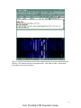
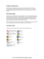
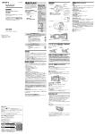
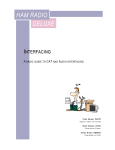
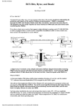
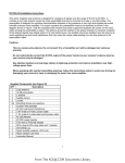
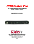
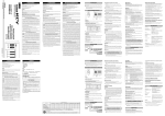
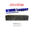
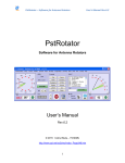
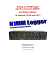
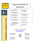
What is PSK31?
As the name implies, PSK (phase shift keying) modulates the phase of a carrier, and the
number ''31'' references the actual bandwidth (31 Hz) occupied by the PSK31 signal.
The software that first implemented PSK31 with a Windows PC and soundcard was
written and developed by Peter Martinez, G3PLX.
Two of the most significant features that make this the ideal mode for digital
communications are; first, the extremely narrow band width, and second, the high
immunity to noise and QRM.
Figure 1 - PSK31 computer display showing frequency spectrum on the left and ‘waterfall’ display
on the right.
Phase modulation has more advantages than CW (morse code). CW uses amplitude
(On/Off) keying. In a noisy or distorted propagation environment, the amplitude of a
signal will shift and vary much more than the phase of a signal. When compared to CW,
PSK31 is a much more resourceful, and robust operating mode.
The baud rate used by PSK31 is 31.25 baud. This is fast enough to handle most
operators’ manual typing capabilities, a speed of about 50 words per minute. It is
intended as a means of keyboard to keyboard communication between two or more
operators, using a very small amount of frequency spectrum.
By comparing the small bandwidth of PSK31 and measuring its gain against a CW filter
of 500 Hz; 10 * log (500/31) dB = 12 dB, quickly reveals that a CW transmitter must put
out 15 to 18 times more power than a PSK31 transmitter, just to achieve the same signal
to noise ratio at the receiving station. This means lower power transmitters and smaller
antennas may be used with good results.
Fifteen to eighteen times relative to 100 watts CW translates into 5-7 watts PSK.
1
From The N3UJJ.COM Document Library
The Background and Philosophy of PSK31
The following is by Peter Martinez, G3PLX, developer of PSK31.
“PSK31 is the result of my belief that the present batch of "data" modes have left a gap
in amateur radio operating, the gap that was previously filled by AMTOR or even
traditional RTTY, in which two or more operators chat to each other on an open channel.
Modes such as packet radio, Pactor, and others, are highly complex, are unsuited to
multi-way conversations, and in particular, the long block lengths introduce an
unacceptable delay in the processing of text such that even normal conversation is
unpleasant and quick-break question/answer sessions are impossible.
The move to automated unattended message forwarding has left a gap in the person-toperson communication field, and PSK31 is an attempt to remedy this situation with a
simple but efficient code structure coupled with the narrowest possible bandwidth, and
with only enough error-correction to match typical typing-error rates, and with no timeconsuming synchronization, changeover, and ARQ processes.
The 31 baud BPSK modulation system used in PSK31 was introduced by SP9VRC in
his SLOWBPSK program.
Instead of the traditional frequency-shift keying, the information is transmitted by
patterns of polarity-reversals (sometimes called 180-degree phase shifts).
This process can be thought of as equivalent to sending information by swapping-over
the two wires to the antenna, although, of course, the keying is more usually done back
in the audio input into the transceiver. A well-designed PSK system will give better
results than the conventional FSK systems that amateurs have been using for years,
and is potentially capable of operation in much narrower bandwidths than FSK. The 31
baud data rate was chosen so that the system will handle hand-sent typed text easily.
There is a problem with PSK keying which doesn't show up with FSK, and that is the
effect of key-clicks.
We can get away with hard FSK keying at moderate baud rates without generating too
much splatter, but polarity reversals are equivalent to simultaneous switching-off of one
transmitter and switching-on of another one in anti-phase: the result being key-clicks that
are TWICE AS BAD as on-off keying, all other things being equal.
So if we use computer logic to key a BPSK modulator such as an exclusive-or gate, at
31 baud, the emission would be extremely broad. In fact it would be about 3 times the
baud rate wide at 10dB down, 5 times at 14dB down, 7 times at 17dB down, and so on
(the square wave Fourier series in fact).
The solution is to filter the output, or to shape the envelope amplitude of each bit which
amounts to the same thing. In PSK31, a cosine shape is used. To see what this does to
the waveform and the spectrum, consider transmitting a sequence of continuous
polarity-reversals at 31 baud. With cosine shaping, the envelope ends up looking like
full-wave rectified 31Hz AC. This not only looks like a two-tone test signal, it IS a twotone test signal, and the spectrum consists of two pure tones at +/-15Hz from the center,
and no splatter. Like the two-tone and unlike FSK, however, if we pass this through a
2
From The N3UJJ.COM Document Library
transmitter, we get inter-modulation products if it is not linear, so we DO need to be
careful not to overdrive the audio.
However, even the worst linear will give third-order products of 25dB at +/-47Hz (3 times
the baud rate wide) and fifth-order products of 35dB at +/-78Hz (5 times the baud rate
wide), a considerable improvement over the hard-keying case. If we infinitely overdrive
the linear, we are back to the same levels as the hard-keyed system.
There is a similar line of reasoning on the receive side. The equivalent to "hard-keying"
on the receive side is a BPSK receiver which opens a gate at the start of a bit, collects
and stores all the received signal and noise during the bit, and then "snaps" the gate
shut at the end. This process gives rise to the receive-side equivalent of key-clicks,
namely side-lobes on the receiver pass band. So, although this "integrate-and-dump"
method is 100% efficient in the task of sorting out signal from noise, it will only reject
signals by 10dB at 3 times the baud rate wide and so on, the same spurious rejection
figures that we got as spurious emission figures for the transmit side.
The PSK31 receiver overcomes this by filtering the receive signal, or by what amounts to
the same thing, shaping the envelope of the received bit. The shape is more complex
than the cosine shape used in the transmitter: if we used a cosine in the receiver we end
up with some signal from one received bit "spreading" into the next bit, an inevitable
result of cascading two filters which are each already "spread" by one bit.
The more complex shape in the receiver overcomes this by shaping 4 bits at a time and
compensating for this inter-symbol interference, but the end result is a pass band that is
at least 64dB down at +/-31 Hz and beyond, and doesn't introduce any inter-symbol
interference when receiving a cosine-shaped transmission.”
PSK Frequencies
Band
Digital Frequencies (kHz)
160 meter
183815
80 meter
3575 - 3585 / 3620 - 3640
40 meter
7060 - 7080
30 meter
10130 - 10145
20 meter
14065 - 14090
17 meter
18100 - 18110
15 meter
21060 - 21090
12 meter
24920 - 24930
10 meter
28110 - 28125
3
From The N3UJJ.COM Document Library
Software
All of the ‘brains’ for PSK31 are in your computer. The transceiver provides a way to
receive and transmit the signal but the filtering, decoding, and encoding uses the power
of your sound card and the magic of software.
The following, lists various software programs available for PSK31. Some also include
other PC/radio communication modes. Some are free; others are commercial and cost
money. Probably, the most popular program is DIGIPAN.
DIGIPAN
Manual for
DIGIPAN
HAMSCOPE
MIXW
WINPSK
WINWARBLER
W1SQLPSK
http://www.digipan.net/
http://kk7uq.com/html/manual.htm
http://www.qsl.net/hamscope/HamScope.html
http://www.mixw.co.uk/product/productmixw.htm ($)
http://www.qsl.net/ae4jy/winpsk.htm
http://www.dxlabsuite.com/winwarbler
http://www.faria.net/w1sql/download.htm
Before you go on the air, be sure you read the user’s manual or the help files relating to
the software you plan to use.
Hardware
Several things are necessary for you to be able to operate on PSK31. The first, you
already have if you’re active on HF - your transceiver. If you don’t have an HF rig then
see the section at the end ‘Alternative Rigs’.
Next you’ll need an interface, something you can build yourself or buy (see ‘Where to
Get an Interface’ at the end of this paper).
Third is a computer; theoretically anything running Windows 95 will do, but realistically a
Pentium 266 or faster with Windows 98 or higher is better.
A fourth would be an antenna of some type. This will be determined by your location but
as always, should be as high and in the clear as much as possible. Having said that,
even attic antennas will work with PSK!
4
From The N3UJJ.COM Document Library
Transceiver Settings
Be sure all speech compression is OFF.
Set the mode to single sideband - USB.
Transceiver receive filter set to 4 KHz (or higher) if your transceiver will allow this
independent of the mode setting. Remember that the serious filtering is done by the
sound card and software. However, there may still be problems caused by a strong
signal within the pass band of the rig’s filter affecting the AGC.
Turn the receiver AGC off if possible.
Open a window on your computer with the PSK software of your choice.
Connect a watt meter and dummy load to the output of your transceiver, click on the
PSK software ‘TX’ menu button and adjust the speaker volume slider on the Windows
taskbar tray for an output power reading of about one third to one half the power you
would normally see when operating CW.
Transmitters these days, for the most part, are not designed for 100% duty cycle and
digital modes, like PSK31, and are ‘on’ all the time you are transmitting (like holding your
key down continuously on CW).
DO NOT operate your transceiver at more than half its maximum power
level rating!
Once you have the power level set, type a few characters and watch the power meter.
As you type, the text you are sending should cause the meter pointer to have a slight
jitter. If you have the LINE OUT/MIC IN level set properly, you should see the power
move slightly upwards. At no time should you see the power level go above 50% of your
transceiver’s rated power output. If it does go higher, simply turn the Transmit Drive level
down, using the transmit level command in your software.
At no point should you see any ALC activity on your transceiver. If you do, be aware
that you are creating unnecessary distortion.
Once the levels are set on your transceiver you should not have to touch the rig’s
controls again.
All future levels are set into and out of the sound card using the volume and wav controls
built into the sound card “control panel” software. In DigiPan, these controls are easily
accessed from the task bar at the top of the screen. Simply click on “configure” and use
the “Transmit Drive” (see fig. 2), command to properly drive the transceiver so that no
ALC action is observed. This avoids causing phase distortion or overdriving the inputs of
your transceiver.
5
From The N3UJJ.COM Document Library
Figure 2 – Setting transmit drive.
Vox
In PSK31 and other digital modes, we do not use the VOX (voice operated relay) circuits
in our transceiver to control changeover from transmit to receive and back. Switching is
done either by using the COM port on your computer or by sound operated switching
built into the interface to switch the rig as the VOX circuits are too slow, digitally
speaking.
Less Is Better Than More
Many of us will be using transceivers that require using the microphone connector for
PSK31 input. If this is the case, and you plan to drive the microphone input with your
sound card (LINE OUT), then the level from the sound card should be comparable to the
output level of your microphone.
While many Sound Blaster™ compatible sound cards have the capability to be set for
high or low level outputs, these outputs are almost always much too high for the input
level to the microphone port of your transceiver.
6
From The N3UJJ.COM Document Library
If you cannot use the sound card “Control Panel (settings)” in Windows (or your PSK31
software) to decrease the output level of your sound card to meet the level requirements
of your microphone input, then you should use a resistive attenuator in your hardware
interface to reduce the LINE OUT level to your transceiver MIC input. The idea is to keep
your audio signal at a low enough level to have a clean PSK31 signal on the air.
PSK31 Display
PSK31 programs use digital signal processing (DSP) to perform very narrow filtering and
then decode the resulting sounds into characters on the receive screen. The display,
shown at figure 3, is how a typical PSK software spectrum (panoramic waterfall) window
appears.
A bright yellow bar with the red diamond-shaped cursor in it is a PSK31 station. To the
left and right of the station select cursor, are other PSK31 stations. Some appear weaker
and others will display brighter, which indicates stronger signals. Although some signals
in the display appear weak, they will still print perfect copy.
The most recent receive signals are displayed at the top of the PSK software waterfall
display. To the left of the cursor, is another PSK31 station that is almost too weak to
copy.
Figure 3 - Frequency is plotted horizontally, and time is plotted vertically, with the earliest at the
bottom. Strength is indicated by color, increasing from blue to yellow.
To tune and receive any of these stations, simply point to the signal with the mouse and
click! The diamond-shaped cursor will jump immediately to the center of the station
signal and the text from the station will begin to appear on screen in the receive window.
You can read the IMD of the selected station on the lower feature bar in most PSK
software programs. A good signal and ideal IMD is between -22 and -32. See Figure 1.
In order for the program to provide a panoramic display with point-and-click tuning of
stations, it is necessary for your transceiver to provide both panoramic reception and
transmission. The receive band pass should be capable of receiving a large number of
PSK31 stations at one time. Hence the transceiver filter setting of 4 KHz or greater for
receive. The effects of the transmitter filter will be seen in falling power output levels as
you approach the filter edges.
7
From The N3UJJ.COM Document Library
Figure 4 - A screen shot showing various PSK31 signals with copy on the trace with the diamond
at the top. The numbers at the top of the signal traces – 1000, 2000, & 3000 – indicate Hertz
(Hz) relative to the receiver frequency.
8
From The N3UJJ.COM Document Library
Where to Get an Interface
The following are not endorsements for any particular brand or product, merely a
resource for your own use when searching for the interface that suits you best.
West Mountain Radio: RIGblaster
http://www.westmountainradio.com/
Tigertronics: SignaLink
http://www.tigertronics.com/
MFJ: 127x series of Soundcard-to-Rig Interfaces
http://www.mfjenterprises.com
Rascal: Soundcard interface kits and more
http://www.packetradio.com
(Be aware that there have been complaints about parts quality and support from this
company.)
WA8LMF Interface
http://members.aol.com/wa8lmf/ham/tonekeyer.htm
ProData Interface
http://www.ham-kits.com/ProData1.htm
MicroKEY USB Interface (uses USB instead of serial port)
http://www.microham.com/mk.html
Saratoga Ham EZ-PSK
http://www.saratogaham.com/ezpsk/
Additional Software sites
http://www.packetradio.com/freeware.html
http://www.qsl.net/wm2u/psk31.html
Other information
Article by Peter Martinez, G3PLX http://det.bi.ehu.es/~jtpjatae/pdf/p31g3plx.pdf
Radio Amateurs of Canada - links to digital modes of all kinds
http://www.rac.ca/opsinfo/infodig.htm
9
From The N3UJJ.COM Document Library
Homebrew your own
Part values are, for the most part, non-critical and may be varied to fit whatever you
have on hand as you will see from the examples that follow.
Figure 5 – Typical interface - From http://www.waypoint.com/users/~discobay/Sound_Card_Presentation.htm
This one uses a fixed attenuator depending on the software to adjust.
Figure 6 – Typical interface -
This one from http://www.jbgizmo.com/page28.htm Has pcb layouts and parts list
This design has adjustments in both receive and transmit audio legs.
10
From The N3UJJ.COM Document Library
Figure 7 – Typical interface - Schematic from http://www.hamtechnet.com/techtips/
This example has the adjustment in the transmitted audio path along with some bypass
capacitors for RF on the COM port, on the microphone side, and the push-to-talk (PTT) circuit. It
also has a LED (light emitting diode) to indicate when the transmitter is keyed.
Still another site with a schematic and an article describing the hardware in pdf format is
http://www.sparetimegizmos.com/Downloads/Sound%20Card%20Buddy.pdf
As you can see, the circuits designs are fairly standard with two transformers, some
sound level adjustment (attenuator), either on both sound from and to rig or just on the
sound to the rig’s mic circuits, and an optocoupler of the 4N25-4N33 (or equivalent)
series.
You could go cheaper by not using transformers and substituting a transistor for the
optocoupler. However, you risk possible damage to your rig and a strong possibility of
hum and noise which equates to a crummy signal.
11
From The N3UJJ.COM Document Library
Mine, Mine!
Figure 9 - Schematic
Figure 8 – Cover view
Figure 10 – Inside view of components
My design is one cobbled together from a couple of circuits I found on-line some years
ago. It has an added LED to indicate transmitter activity.
The technology may be termed ‘epoxy’ style. The transformers are inverted and glued
with standard two part epoxy (the 5-minute stuff wouldn’t hold!) and the opto socket
glued to the side of one of them. The plastic case prevents common grounds on the
input and output jacks (negating the transformer isolation).
12
From The N3UJJ.COM Document Library
Problem with Sounds
Shut off those nice Windows sounds by going to Control Panel/Sounds and Audio
Devices/Sounds and selecting ‘No Sounds’ under ‘Sound Schemes’. You really don’t
want to have them going out over the air every time you hit a wrong key or an e-mail
comes in!
Alternative Rigs
If you don’t own an HF rig then a low cost alternative is one of the single band rigs from
Small Wonder Labs (http://www.smallwonderlabs.com) in New Hampshire costing $100
each and $30 extra for the case. If you just want something to experiment with they
have a very inexpensive 80M kit called the ‘Warbler’ for $49. I’ve bought several qrp
rigs from them over the years and find their service fantastic.
Look for good deals on used HF rigs. Even slight vfo drift problems are compensated for
by the automatic frequency control (AFC) feature in most PSK software.
Contents of CD
This article “What Is PSK31” both in Word format and Adobe pdf format.
13
From The N3UJJ.COM Document Library