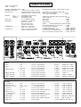
1
ALLEN&HEATH
GL3300
Dual Function Audio Mixing Console
USER GUIDE
PUBLICATION: AP3102
LIMITED ONE YEAR WARRANTY
This product has been manufactured in the UK by ALLEN & HEATH and is warranted to
be free from defects in materials or workmanship for a period of one year from the date of
purchase by the original owner.
To ensure the high level of performance and reliability for which this equipment has been
designed and manufactured please read this User Guide before use.
In the event of a failure notify and return the defective unit to ALLEN & HEATH or its
authorised agent as soon as possible for repair under warranty subject to the following
conditions:
1. The equipment has been installed and operated in accordance with the instructions in the
User Guide.
2. The equipment has not been subject to misuse either intended or accidental, neglect, or
alteration other than as described in the User Guide or Service Manual, or approved by
ALLEN & HEATH.
3. Any necessary adjustment, alteration, or repair has been made by ALLEN & HEATH or
its authorised agent.
4. The defective unit is to be returned carriage prepaid to ALLEN & HEATH or its authorised
agent with proof of purchase.
5. Units to be returned should be packed to avoid transit damage.
These terms of warranty apply to UK sales. In other territories the terms may vary according
to legal requirements.
This product complies with the European
Electromagnetic Compatibility Directives 89/336/EEC
& 92/31/EEC and the European Low Voltage Directives
73/23/EEC & 93/68/EEC.
NOTE: Any changes or modifications to the console not approved
by Allen & Heath could void the compliance of the console and
therefore the user’s authority to operate it.
Manufactured In England
Allen & Heath Limited.
Kernick Industrial Estate,
Penryn, Cornwall, TR10 9LU, UK
http://www.allen-heath.com
copyright © 2001 ALLEN & HEATH. All rights reserved
2
Publication ...................... AP3102 Issue 4
GL3300 USER GUIDE
INTRODUCTION
The GL3300 continues ALLEN & HEATH’s commitment to provide high quality audio mixing consoles
engineered to meet the exacting requirements of today’s audio business. It brings you the latest in high
performance technology and offers the reassurance of over two decades of console manufacture and
customer support.
This user guide presents a quick reference to the function, application and installation of the GL3300. For
further information on the basic principles of audio system engineering please refer to one of the specialist
publications available from bookshops and audio equipment dealers.
Whilst we believe the information in this guide to be reliable we do not assume responsibility for
inaccuracies. We also reserve the right to make changes in the interest of further product development.
SERVICE AND TECHNICAL SUPPORT
Under normal conditions the GL3300 does not require user maintenance or internal calibration. Any
service work required should be carried out by qualified service personnel only.
We are able to offer further product support through our worldwide network of approved dealers and
service agents. To help us provide the most efficient service please keep a record of the console serial
number, and date and place of purchase to be quoted in any communication regarding this product.
SAFETY WARNING
Mains electricity is dangerous and can kill. Mains voltage is present within the
power supply unit provided with the console. Do not remove the power unit cover with
mains connected. The correct mains voltage setting is indicated on the rear of the
power unit. Check your mains wiring and earthing before switching on.
DO NOT REMOVE THE MAINS EARTH CONNECTION!
The console chassis is connected to mains earth to ensure your safety. Audio
0V connects to the console chassis internally. Should problems be encountered with
ground loops operate the audio ground lift switches on connected equipment
accordingly or disconnect the cable screens at one end. Refer to the section on
'EARTHING' later in this User Guide.
PRECAUTIONS.
z
AC POWER:
z
CONNECTIONS: Use audio connectors and cables only for their intended purpose. Do not
connect any source of AC or DC power to the console audio connectors. Do not
connect the output of power amplifiers directly to the console.
z
CLEANING:
z
LUBRICATION: The faders, switches and potentiometers are lubricated for life. The use of
electrical lubricants on these parts is not recommended.
z
DIRT, DUST, SMOKE and MOISTURE: Prevent damage to the moving parts, such as faders
and potentiometers, and cosmetics by avoiding drinks spillage, tobacco ash and
smoke, and exposure to rain and condensation. Protect from excessive dirt,
dust, heat and vibration.
GL3300 USER GUIDE
Check the power unit for correct AC mains voltage setting before switching on.
Allow adequate space around the unit for ventilation.
Avoid the use of chemicals, abrasives and solvents. The control panel is best
cleaned with a soft brush and lint-free cloth. To remove stubborn marks (such
as chinagraph pencil) isopropyl alcohol may be used.
3
INSTALLING THE POWER SUPPLY UNIT
Refer to the SAFETY WARNING on the first page of this User Guide.
The GL3300 is supplied with either the RPS9 or the RPS11 power supply unit. The console can
work with either supply. Consoles from serial number 004196 have been shipped with the RPS11.
A second power supply can be connected through the optional RPSD2 combiner to provide a backup
or ‘redundant’ supply.
The power supply converts the AC mains voltage to the regulated positive and negative DC voltages
required to power the console. It also provides the +48V DC phantom power voltage for use with high
quality powered microphones. Input is via the IEC mains cable with moulded plug suitable for the local
supply as provided with the unit. The IEC mains input socket includes a fuse and voltage selector
which must be set to match the local supply voltage. The output connects to the console via a 2.9
metre DC power cable fitted with locking 5 pin XLR plug. The RPS9 has a captive DC cable. The
RPS11 has a separate DC cable which connects to the power supply using a screw locking 10 pin
circular plug. To ensure the best performance we recommended that you do not extend the DC cable
or site the power supply more than 2.9 meters away from the console. The power supply may be
operated free standing or mounted in a 19” rack. The RPS9 requires 2U rack space. The RPS11
requires 3U rack space. As with any power supply unit it is best positioned away from the console or
other signal processing equipment containing sensitive low level audio signals to avoid the possibility of
hum pickup. Please read the warnings printed below:
Check that the voltage indicated in the fuseholder window is the
same as the mains supply in your area.
To avoid the risk of fire replace the fuse only with the correct
type and value as specified on the unit.
It is normal for the power unit to dissipate heat. Ensure adequate
ventilation around the unit. Do not cover the unit or position it on
soft furnishings during operation. Do not position other equipment
known to generate significant amounts of heat below the unit. It is
recommended that rack units containing high power amplifiers and
other heat dissipating equipment are fitted with cooling fans.
Always switch the power unit off before connecting or
disconnecting the console power cable.
This unit contains no user serviceable parts. Do not remove the
cover. Refer servicing to qualified service personnel only.
The RPS9 and RPS11 power supplies conform to safety standard
4
EN 60065
GL3300 USER GUIDE
EARTHING THE AUDIO SYSTEM
The console chassis is connected to mains earth via the DC power cable. Audio 0V is connected to the
chassis and therefore mains earth. In this way all signal returns and connector shields are connected to
mains earth at the console.
To ensure operator safety do not remove the earth connection
from the power supply mains plug.
For best performance it is important that the earth system is solid, clean and noise-free. To prevent mains
born and external interference pickup from lighting equipment, motors and other mains powered
equipment it is recommended that a separate 'clean' mains distribution outlet is used for the audio system.
All signal cables should have their screens connected to earth at the connector. If earth (ground) loop
problems result in audible hum or buzz then disconnect the cable screen connection at one end, usually the
destination end. This may be done within the cable plug or by operating the 'ground lift' switch if available
on the connected equipment. Many DI boxes and power amplifiers include this facility.
PLUGGING UP THE CABLES
Where possible use balanced connections to prevent noise and interference pickup especially on long
microphone cable runs. Avoid running audio cables next to mains, computer or lighting cables, or near
thyristor dimmer units, power supplies etc. The use of low impedance sources such as good quality
microphones of 200 ohms or less significantly reduces interference pickup. Many problems can be avoided
by taking time to check that all cables are correctly wired (in-phase) with professional quality cable and
carefully soldered joints. The following wiring convention is used:
XLR
1/4" jack
tip
= hot / +ve/signal / left / send
pin 2 = hot (+ve - in phase signal)
ring
= cold /-ve/ 0V / right/ return
pin 3 = cold (-ve - out of phase signal)
sleeve = 0V earth shield
pin 1 = 0V earth shield
To connect an unbalanced source to a balanced console input, link the cold input (XLR pin 3 or jack ring)
to 0V earth (pin 1 or jack sleeve) at the console. To connect a balanced console output to an unbalanced
destination link the cold output to 0V earth at the console.
)
Switch off the input channel +48V when using non-phantom
powered, line or unbalanced sources.
ADJUSTING THE LEVELS
For best performance it is important that the connected source signals are matched to the "normal operating
level" of the console. Similarly the console outputs should be correctly matched to the operating levels
of the connected amplifiers and destination equipment. If too high the signal peaks will be clipped
resulting in a harsh distorted sound, and if too low the signal-to-noise ratio is reduced resulting in excessive
background hiss.
For best results operate the console with the meters averaging '0' or just below and allowing the loudest
passages and occassional peaks into the 'yellow'. Reduce the gain if the peak indicators flash (red). The
GL3300 produces a standard XLR output level of +4dBu for a meter reading of 0VU. It is advisable to
adjust the power amplifier input gain or fit an attenuator pad if normal console operation results in an output
level too high for the connected amplifier. Normal operation should result in fader levels around the '0'
mark.
The GL3300 has an advanced PFL (pre-fade listen) / AFL (after-fader listen) and channel metering
system to let you listen to and check the level of signals at different points in the signal path without
affecting the main outputs. Use the channel PFL switches to set up the input GAIN controls to read an
average '0' (yellow LED). Signal activity is always shown on the channel meters regardless of fader mute
switch position. The green 'SIG' LED lights at -20dBu to indicate signal presence, the green '0' LED
indicates normal level, and the red 'PEAK' LED warns of potential overload 5dB before clipping.
GL3300 USER GUIDE
5
The ALLEN & HEATH GL3300 represents a breakthrough in price versus performance and functionality.
It offers the professional user a new level of versatility to quickly adapt to the exacting demands of live
sound engineering today. The GL3300 is developed from the successful GL3000 console which includes
innovative 'mode switching' that quickly converts the console from Front-of-House to On-stage Monitor
operation. Apart from continuing the development of this unique feature, the GL3300 packs in more
features and performance at the same price point of the mixer it succeeds.
FEATURES
6
9
Easy to use intuitive layout.
9
16, 24, 32 and 40 channel frames each with customer configurable mono and stereo input modules.
9
Mono and stereo channel bolt-on expanders available to extend up to a maximum 40 channels.
9
Separate safety approved power supply unit.
9
SYS-LINK buss expander option.
9
VU meterpod for 24, 32 and 40 models.
9
4 assignable mute groups for combined channel control.
9
L, R outputs on balanced XLR with inserts.
9
Mono sum output on balanced XLR with mode switching to 'listen wedge' monitor.
9
8 subgroups, with 4 available outputs on balanced XLR with inserts.
9
All 8 group outputs available on 25pin D connector as an option.
9
L-R, mute and pan on each subgroup.
9
2 matrix outputs on faders fed from L, R, 8 subgroups and stereo returns.
9
8 aux sends, 4 on jack, 4 on balanced XLR outputs with inserts.
9
Mode switching to convert console to on-stage monitor status with 8 mono and 1 stereo sends.
9
2 stereo returns with faders and routing.
9
2-track record and replay with level controls.
9
Individual talkback to all aux sends.
9
Extensive monitoring and metering facilities
9
Gooseneck lamp connector.
9
Advanced channel features including +48V, phase switch, lo-cut filter, meter and insert.
9
Direct output on mono channels.
9
4 band 2 sweep EQ with wide ranging frequency sweep and +/-15dB boost/cut.
9
Pre-post aux switching with additional internal link options.
9
Stereo mic/line channels with XLR/Jack inputs and inserts.
9
High performance circuitry used for low noise and sonic purity.
9
High quality, proven reliable parts used throughout.
9
Rear mounted connectors, comfortable soft armrest, wide write-on strips.
9
Rugged metal beam construction for on-the-road rigidity, easily flightcased and transported.
9
Removeable steel base for easy access to individual circuit assemblies.
GL3300 USER GUIDE
OPTIONS & ACCESSORIES
There are a range of options and accessories available for the GL3300 range. All are supplied complete
with fixings and installation and operating instructions. Contact your nearest Allen & Heath dealer if you
wish to purchase an option or accessory.
VU meterbridge
Units from Serial Number 002200 include a built-in VU Meterpod as standard. An optional VU Meterpod
is available for earlier units. Contact your nearest A&H dealer for details.
Expander
The GL3300 can be expanded up to a maximum of 40 input channels. The expander is an 8 channel wide
bolt on module with full function input channels and soft armrest.It can be fitted to the left or right hand
side of the console depending on the console format. The expanders are available in 4 different formats.
8 MONO INPUT CHANNEL EXPANDER
M
Order Code: GL3300-8M
8 STEREO INPUT CHANNEL EXPANDER
S
Order Code: GL3300-8S
4 MONO & 4 STEREO INPUT CHANNEL EXPANDER
MS
Order Code: GL3300-4MS
4 STEREO & 4 MONO INPUT CHANNEL EXPANDER
S M
Order Code: GL3300-4SM
SYS-LINK Buss Expander Kit
The SYS-LINK expander option allows console to console interconnection by means of just two cables.
By connecting two GL3300 consoles together or to any other A&H console fitted with the SYS-LINK
option, the number of input channels can be increased. One console acts as a channel expander (slave)
to the second (master). Please note, the SYS-LINK option kit requires the installation and wiring of a
circuit board (PCB) assembly and should only be fitted by technically competent service personnel.
SYS-LINK BUSS EXPANDER KIT
Order Code: GL3300-SL1
(for one console only)
8 Group Output option Kit
The 8 Group Output option allows direct access to all 8 groups in the console. This is in addition to group
outputs 5-8 on XLR connectors on the rear panel. This option uses one of the SYS-LINK connector
mounting holes and may need to be repositioned if the SYS-LINK option is already fitted. Please note,
the 8 Group Output option kit requires the installation and wiring of a circuit board (PCB) assembly and
should only be fitted by technically competent service personnel.
8 GROUP OUTPUT OPTION KIT
GL3300 USER GUIDE
Order Code: GL3300-8GD
7
RPSD2 Dual Supply Combiner
The RPSD2 is designed to monitor the DC power supply to the GL3300 console. With an additional power
supply the RPSD2 will quickly and silently change over to the backup supply should the original power
supply fail.
RPSD2 DUAL SUPPLY COMBINER
Order Code: RPSD-2/3K
RPS9 POWER SUPPLY
Order Code: RPS9/Volts
(additional power supply for use with RPSD2)
RPS11 POWER SUPPLY
Order Code: RPS11/Volts
(additional power supply for use with RPSD2)
GL3300 Flightcase
The GL3300 may be fitted into a touring flightcase. Contact your A&H dealer for details of your nearest
flightcase manufacturer. The dimension details are provided at the rear of this guide.
Miscellaneous
Please contact your nearest Allen & Heath dealer for the parts listed below.
GL3300 SERVICE MANUAL
Order Code: AP3103
GL3300 SPARES KIT
Order Code: 002-096
MAINS LEAD - EUROPE (2PIN)
Order Code: AH0205
(RPS9 & RPS11 power supplies)
MAINS LEAD - USA C33 (3PIN)
Order Code: AH0323
(RPS9 & RPS11 power supplies)
MAINS LEAD - UK (3PIN)
Order Code: AH0206
(RPS9 & RPS11 power supplies)
RPS11 DC CABLE ASSEMBLY
8
Order Code: 002-225
GL3300 USER GUIDE
SPECIFICATION
0 dBu = 0.775 Volts RMS
0 dBV = 1 Volt RMS
INTERNAL OPERATING LEVEL: -2 dBu
INTERNAL HEADROOM: ........... +21dB channels, +23dB mix to output.
MAX OUTPUTS: ............... ......... balanced +27dBu >2 kohm max load
unbalanced +21dBu >2 kohm max load
METERS: ........ L, R .....................
Groups 1-8 .........
Channels ............
PEAK LEDs: ................................
peak reading 12 segment LED
peak reading 4 LEDs
peak reading 3 LEDs
Turn on 5dB before clipping
METERPOD: ............................... Illuminated VU meters with
Groups 1-8, L, R and
Mono (PFL/AFL) levels
PFL/AFL active indicator
POWER SUPPLY: ......................... RPS9 2U x 19" rack mount
..................................................... RPS11 3U x 19" rack mount
AC Mains input: ........................... range 100V to 240V.AC 50/60Hz
Set with 4 position fuse insert
FREQUENCY RESPONSE:
20Hz to 30kHz +0/-1dB
DISTORTION: THD + Noise at +14dBu 1kHz
Mic in to LR out at +40dB gain .......................... 0.01%
Line in to LR out at 0dB gain ............................. 0.01%
CROSSTALK: . Referred to driven channel at 1kHz
Adjacent channel ............................................... <-100dB
Fader shutoff ................................................. <-90dB
Mute shutoff
................................................. <-90dB
Panpot shutoff ................................................. <-72dB
NOISE: ............ Measured RMS 22Hz to 22kHz bandwidth
Mic input EIN referred to 150 ohm source ........ <-128dB
Line input pre-amp at 0dB gain ......................... <-93dBu
LR output residual noise ................................... <-98dBu 102dB S/N
LR faders '0' no channels routed ...................... <-90dBu 94dB S/N
LR mix noise with 16 channels routed .............. <-86dBu 90dB S/N
Group mix noise with 16 channels routed ......... <-87dBu 91dB S/N
INPUTS:
MIC IN ....................................... XLR ............................. pin 2 hot, 3 cold, balanced ................................. 2 kohms .......... variable -60 to -10 dBu
LINE IN ..................................... XLR ............................. pin 2 hot, 3 cold, balanced ................................. 10 kohms ........ variable -40 to +10 dBu
or
1/4" JACK .................... tip hot, ring cold, balanced ................................. 10 kohms ........ variable -40 to +10 dBu
STEREO LINE IN ..................... XLR ............................. pin 2 hot, 3 cold, balanced ................................. 10 kohms ........ variable -40 to +14 dBu
or
1/4" JACK .................... tip hot, ring cold, balanced ................................. 10 kohms ........ variable -40 to +14 dBu
STEREO RETURN .................. 1/4" JACK .................... tip sig, ring gnd, unbalanced .............................. >6 kohms ........ -10dBV min
2-TRACK RETURN ................. 1/4" JACK .................... tip sig, ring gnd, unbalanced .............................. >16 kohms ..... variable -10 dBV min
INSERT RETURN .................. 1/4" JACK .................... tip send, ring ret, unbalanced ............................. >6 kohms ........ 0dBu (chan), -2dBu (out)
OUTPUTS:
L, R, MONO OUT ..................... XLR ............................. pin 2 hot, 3 cold, balanced ................................. <75 ohms ....... +4 dBu +27 dBu max
GROUP OUT 5-8 ...................... XLR ............................. pin 2 hot, 3 cold, balanced ................................. <75 ohms ....... +4 dBu +27 dBu max
GROUP OUT 1-8 option ........... 25way D type ............ ........ impedance balanced ................................. <75 ohms ....... +4 dBu +27 dBu max
AUX OUT 1-4 ........................... XLR ............................. pin 2 hot, 3 cold, balanced ................................. <75 ohms ....... +4 dBu +27 dBu max
AUX OUT 5-8 ........................... 1/4" JACK .................... tip hot, ring cold, impedance balanced .............. <75 ohms ....... -2 dBu +21 dBu max
MATRIX OUT A-B .................... 1/4" JACK .................... tip hot, ring cold, unbalanced ............................. <75 ohms ....... -2 dBu +21 dBu max
(balance option) .............. 1/4" JACK .................... tip hot, ring cold, balanced ................................. <75 ohms ....... +4 dBu +27 dBu max
2-TRACK SEND ....................... 1/4" JACK .................... tip hot, ring cold, impedance balanced .............. <75 ohms ....... variable +21 dBu max
INSERT SEND ......................... 1/4" JACK .................... tip send, ring ret, unbalanced ............................. <75 ohms ....... 0dBu (chan), -2dBu (out)
DIRECT OUT ............................ 1/4" JACK .................... tip hot, ring cold, impedance balanced .............. <75 ohms ....... 0dBu +21 dBu max
PHONES OUT .......................... 1/4" JACK .................... tip left, ring right .................................................. for stereo headphones 30 to 600 ohms
GL3300 USER GUIDE
9
FRONT PANEL LAYOUT
10
GL3300 USER GUIDE
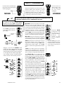
INPUT CHANNELS
For line sources on XLR simply
plug into the XLR with the jack
socket unplugged.
Plug in a microphone or line level source. Use
balanced cables where possible to prevent
interference pickup on long cable runs.
Unbalanced sources may be connected by
linking signal cold to ground (XLR pin 3 to pin
1, jack ring to sleeve) at the connector.
MONO
)
For line sources on
XLR simply plug
into the XLR with
the jack socket
unplugged.
STEREO
Switch off channel +48V when the inputs are connected to nonphantom powered, line or unbalanced sources.
For balanced microphones which require
phantom power select +48V. If required this
switch may be disabled by an internal link.
Use the PFL system to listen
to the signal and fine tune the
gain setting.
φ PHASE reverses the phase of the input
source to correct the phase differences often
encountered in microphone placement, or due
to incorrectly wired cables (pin 3 hot instead of
pin 2). May also be used to minimise acoustic
feedback between closely positioned
loudspeakers and mics in live sound mixing.
The stereo φL reverses the left input phase only
to correct for differences between left and right
signals, or for MS microphone techniques.
MIC/LINE selects line sensitivity on the jack
input when pressed. Or becomes a 20dB pad
for the XLR input when no jack is plugged in.
Plugging a jack into the INSERT socket
breaks the signal path between the input
preamp/filter and the EQ to let you add an
external signal processor such as a compressor
or noise gate into the channel signal path
Use a suitable Y-lead or suitable TRS jack
lead to connect to the external processor.
GAIN matches the level of the input source to
the normal operating level of the console.
Adjust this to read an average '0dB' on the
channel meter (yellow LED). Use the PFL
system to listen to the signal and fine tune the
gain.
Separate GAIN
controls for L and
R inputs let you
adjust the balance
between
the
sources, or treat
each as a separate
source.
Both L and R up gives you a
true stereo channel. Press both
to mono the source. Press just
one to select one side only as
a mono source.
100Hz lo-cut filter removes low frequency
noise such as microphone pops, stage noise
and transport rumble before the pre-amp stage.
The lo-cut filter is independent of the equaliser.
The 4-band EQ lets you adjust the tonal
quality of the sound in 4 separate bands. HF
(treble) and LF (bass) are shelving while the 2
mid bands MF1 & MF2 are peak/dip with a Q
of 1.6. This is optimum for both corrective and
creative equalisation. The controls are centre
detented for centre flat response. Press EQ IN
to switch the EQ into the signal path.
The 2 mid frequency bands on the mono input
channel may be swept across a wide frequency
range to tune into the exact frequency required.
The mid bands are overlapping to provide
additional cut or boost when required.
The EQ on the stereo inputs has the 2 mid
frequencies at 250Hz and 2.5kHz. This
provides optimum control over boomy or boxy
sounds (MF2), and to add presence and sparkle
to vocals etc. (MF1). The stereo channels are
well suited to stereo miking, dual mic mixing,
or returning keyboards and effects processors
to the mix and monitors.
GL3300 USER GUIDE
11
8 AUX SENDS
8 AUX SENDS provide ample feeds for foldback monitors and effects. These
are in two groups of four each with a POST/PRE switch to source the sends either
pre-fader or post-fader.
AUX 1-4 feed balanced XLR outputs capable of driving long cable runs and
include INSERT points. These are normally used to provide MONITOR SENDS
to the performers and stage crew, although they can be used for additional effects.
Plug a graphic EQ into the insert to 'ring out the monitor' (tune) to the stage
acoustics to minimise feedback. The effect of the EQ can be listened to using the
aux master AFL system. Monitor sends are usually set pre-fade, although some
sources such as radio mics can be set post-fade to avoid 'dressing room' talk spill.
Note stereo input channel aux sends are the mono sum of left and right.
AUX 5-8 feed jack outputs and are normally used to provide EFFECTS SENDS
to external devices such as reverb and delay effects units. Effects sends are set
post-fade so that the amount of effect (wet signal) is always relative to the position
of the fader (dry signal). Adjust the amount of effect required for each channel
using its AUX control. The effect is returned to the mix through another channel,
usually the stereo return described later in this guide.
Note; when the GRP/AUX REVERSE 5-8 switches are pressed in the master
section AUX SENDS 5-8 feed XLR outputs with inserts. GROUPs 5-8 are rerouted to AUX 5-8 jack outputs.
POST-FADE sends are always post-EQ, post-mute. PRE-FADE sends are set
post-EQ, post-mute as standard, but may be internally reset to be pre-EQ, pre-mute
or post-EQ, pre-mute. Each AUX SEND may be internally set to be permanently
pre or post-fade rather than follow the panel switch. Refer to the Internal Link
Options section in this user guide.
PAN positions the channel signal between the Left L and Right R outputs when
the L-R ROUTING switch is pressed. PAN also positions the channel signal
between the ODD groups e.g. 1, 3, 5, 7 and EVEN groups e.g. 2, 4, 6, 8 when the
ROUTING switches are pressed. This lets you position the sounds within a stereo
image. In this way subgroups may be set up in mono by turning the PAN fully left
L or right R or in stereo by setting PAN between L and R to feed a pair of groups.
Normal fader
position
MUTE switches the signal off when pressed. A muted channel is indicated by the
illuminated switch. The channel meter continues to indicate pre-mute and fader
channel activity. The mute switch also illuminates when the channel is muted by
one of the 4 MUTE GROUPs.
Switches M1, M2, M3, M4 next to the fader, assign which mute group the input
channel will be assigned to. This is controlled by the MUTE GROUP switches
located in the master section.
A 100mm long throw FADER provides +10dB boost above the normal '0'
operating level.
A 3 LED CHANNEL METER system shows signal activity at all times. The green
SIG LED indicates signals greater than -20dBu, the yellow '0' LED represents
normal operating level, and the red PEAK LED warns of potential overload 5dB
before clipping. Set the channel so that the meter averages '0'. Back the gain off
if the red peak LED flashes.
Pressing PFL automatically interrupts the headphone monitor signal to let you
listen to the channel pre-fader signal without interrupting the main console
outputs. The signal level is shown on the LR monitor bargraph meters, and on the
Mono/PFL meter if the optional meterpod is fitted. In this way each sound can be
correctly lined up and checked at any time.
DIRECT OUT taps the signal off post fader for connection to external processing
or recording equipment. This is ideal for multitrack recording during live
performance as each channel can be recorded onto a separate track for mixdown
later. The direct out signal can be set pre-fader if the internal link option is changed.
Refer to the Internal Link Options section in this user guide.
12
GL3300 USER GUIDE
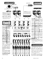
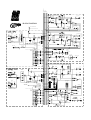
INPUT BLOCK DIAGRAMS
GL3300 USER GUIDE
13
AUX SENDS
EFFECTS
GROUPS
MONITORS
AUX 5-8 jack outputs to
send selected signals to
external effects devices.
AUX 1-4 balanced outputs
feed foldback monitors with
graphic EQ on INSERT to
tune out acoustic resonances
or to minimise feedback.
AFL lets you check the
output signal after the insert
and master level control.
GROUPs 5-8 are available on
balanced XLR outputs to drive long
cable runs. INSERTS are provided
on all 8 groups to insert signal
processing devices such as
compressor/limiters into the signal
path. Use these outputs as additional
speaker feeds or for recording. In
'MONITOR MODE', GROUPs 58 become AUX 5-8 outputs to provide
a total of 8 dedicated stage monitor
sends on XLR with inserts.
MODE
SWITCHES
Decide your required
console configuration
and set these recessed
switches using a pen tip
or similar.
Press REVERSE to
swap the group fader
section with the aux
master section. This
represents 'MONITOR
MODE' where the aux
mix is on the fader with
METER, AFL, MUTE,
balanced XLR output and
INSERT for full control of
the monitor mix. AFL
lets you listen to and
check the effect of the
inserted graphic EQ or
similar
processing
device.
In this mode the group
mix is available on the
aux master controls to
feed the jack outputs, as
well as the subgroup
section.
Mix and match this fader
section as you require.
For example you could
have 2 as monitor sends,
4 as subgroups, and 2 as
additional outputs.
14
{
These PAN settings show subgroup 1-2 as a stereo pair, and
subgroup 3-4 panned off centre to slightly close the stereo image,
useful when the speaker stacks are widely spaced and the front
rows of the audience may be confused by a full stereo image.
MUTE switches the signal off . Muted
groups are indicated by red LEDs.
AFL lets you check the output signal
after the insert and fader control.
Each group has 4 way LED metering
providing signal presence indication
and peak warning which illuminates
approximately 5dB before clipping.
The subgrouping is always fed from
the group mix regardless of GRP/
AUX REVERSE.
All the XLR outputs operate at a
nominal high level +4dBu. Ensure
correct matching to external
equipment.
SUBGROUPING
Using subgroups lets you group similar
sounds together under control of a
single fader (mono subgroup), or
panned pair of faders (stereo
subgroup). For example, the mics on
a drum kit (kick, snare, overheads,
toms), backing vocals, stage mics,
orchestral wind section etc.
Select L-R ON to route a group to LR as a subgroup. Position the signal
within the stereo image using PAN.
GL3300 USER GUIDE
MUTE GROUPS 1-4
The L and R inputs are on individual
jack sockets. Sensitivity is for line level
signals of -10dBV and more. For a
mono source plug into the L input only.
AUX 1-8
GRP 1-8
LEFT
RIGHT
MTX A-B
PFL
AFL
STEREO RETURNS
AFL
AUX (1-4) MIX
AUX 1-4 OUT
AUX
INSERT
SL
BAL
2=+
-
-2dBu
+
+4dBu
PEAK
+6
0
SIGNAL
FADER
GROUP
INSERT
SL
POT
FADER
-2dBu
G
+
GROUP (1-4) MIX
MTX A
MUTE
MTX B
AUX/GROUP REVERSE
AFL
SUBGROUPING
METER SOURCE
SELECT
POT
VU
L-R
PAN
FADER
AFL
AUX (5-8) MIX
SL
AUX (GROUP) 5-8 OUT
TIP = +
-
RING = PEAK
+6
0
SIGNAL
GROUP (5-8) MIX
FADER
GROUP (AUX)
INSERT
SL
BAL
GROUP (AUX) 5-8 OUT
2=+
+
POT
FADER
-2dBu
IMPEDANCE
BALANCED
-2dBu
+4dBu
G
MTX A
+
MUTE
MTX B
AUX/GROUP REVERSE
AFL
VU
SUBGROUPING
METER SOURCE
SELECT
POT
PAN
L-R
FADER
2 Stereo return inputs are provided to return the
effects ('wet') signal, usually from a stereo device, to
the mix. These are normally routed to the main LR mix but may be returned to the corresponding
pairs of subgroups for group effects (1-2 or 3-4).
FADER
L-R
1-2(3-4)
PAN
+
L/MONO
+
A-B
R
FADER
BAL OUT OPTION
MATRIX A(B) MIX
These inputs may also be used as additional line
inputs, or as external inputs to the matrix mix by
selecting A-B. The BAL control adjusts the balance
between left and right signals, or can be used as a pan
control to route the signal to one side only by rotating
fully. A smooth travel 60mm fader provides precise
control of the level.
STEREO
RETURN
BAL
SL
+
-
MATRIX A(B) OUT
0dBu
AFL
TALKBACK
Recording from the
GROUPS
There are two ways of recording from the
groups. One is to connect the multitrack inputs
to the group INSERT send and link the send
and return (jack tip to ring) together.
Alternatively, install the 8 group output option.
All outputs are impedance balanced +4dBu or
-10dBV and available on a single 25 way D
type connector on the rear panel. (Refer to the
Options and Accessories section.)
GL3300 USER GUIDE
Balanced XLR input for a gooseneck (or
cable) microphone for the operator to
talk to the aux sends (foldback monitors).
+48V may be enabled by means of an
internal link for microphones which
require phantom power. Refer to the
Internal Link Options section in this
user guide
Talk to the required aux mix by pressing
and holding the appropriate switch. Talk
to several at the same time by holding
down a combination of switches.
The ability to talk to individual auxes is
important when using the console for
stage monitoring and cueing the
performers.
15
MATRIX
Two matrix outputs A and B are provided. These are additional outputs on TRS jacks
controlled by 60mm smooth travel FADERS and with AFL monitoring to check the
post fader signal. The matrix mix is created from the 8 groups, L and R by adjusting
the MTX level controls. These signals are fed post their respective faders. Note that
in 'MONITOR MODE' (REVERSE selected) the matrix is still fed from the groups
(now routed via the aux masters). External inputs to the matrix are available from
the adjacent stereo returns. The matrix outputs can be balanced by fitting the balance
option, refer to the Internal Link Options section in this user guide.
The matrix outputs satisfy a host of applications. Traditionally the matrix has been
used to feed additional speaker systems such as auditorium balcony speakers. These
are fed through delay units to compensate for acoustic delay due to the distance from
the main speakers. Here the balance of the mix may be slightly different from the
main speakers, for example vocal light to keep the vocals nearer the stage. Adjusting
the balance of the groups to the matrix achieves this. Another example is live sound
recording where the PA mix may be necessarily lacking in bass due to the acoustic
output of the orchestra or 'backline'. Compensate for this by recording from the
matrix with the group feeds adjusted for an even recording balance.
MUTE GROUPS
MUTE GROUPs let you mute a selected combination of channels with a single key
press. Applications include muting unused channels when mixing different bands,
muting all channels except 2-track playback during intermission, muting effects,
muting a bank of radio mics during an instrumental number, muting stage mics during
scene changes etc....
The GL3300 includes 4 MUTE GROUPs controlled by a bank of 4 large illuminated
buttons between the Group and L-R faders. These latching switches may be selected
one at a time or together.
>
To set up a mute group, press one of the mute group selector switches M1, M2, M3,
M4 on the input channels. Now press the corresponding mute group switch in the
master section. The mute group switch and the channel mute switch will illuminate and
the input channel signal will be muted.
An input channel can be a member of more than one mute group by simply pressing
another channel mute group selector switch.
<
<
<
2
MUTE
GROUP
16
GL3300 USER GUIDE
LAMP
Plug in a 12V gooseneck lamp to provide illumination of the control
panel. This should be a BNC connector type.
2-TRACK
Individual jack sockets are provided for left and right inputs (returns)
from and outputs (sends) to a stereo recorder such as a DAT or
cassette machine.
Alternatively the RETURN may be used for stereo intermission
replay from a CD or similar to the main mix by pressing L-R. An
LED warns that replay is on.
The SEND may be used for recording the performance in stereo, or
to feed alternative speakers, drive an induction loop hearing aid
system, or to feed a stereo broadcast etc. The send is connected post
L-R faders as standard.
Separate send and return level controls adjust the signal to the
required line level and sensitivity. The console can work with both
high (+4dBu) and low (-10dBV) level equipment.
PHONES MONITOR
FOH
Plug in stereo headphones (30 to 600 ohms recommended) under the
armrest. Adjust the LEV control for comfortable listening level.
The phones and 12 segment bargraph meters normally monitor the
post-fade L-R mix. Press 2-TRK to monitor the return from a stereo
recorder if connected.
Pressing AFL anywhere on the console automatically overrides the
monitor with the selected AFL signal. Pressing PFL overrides both
the monitor source and any selected AFL. This feature lets you listen
to an AFL source, group for example, and check channel signals
simply by pressing and releasing the required PFL buttons. PFL or
AFL selected is indicated by means of a large red LED above the
meters.
LR SUM
AFL /PFL
ON STAGE
MONITOR
MONITOR MODE
Press the mode switch for STAGE MONITOR application. The
mono out XLR now feeds the monitor engineers 'listen wedge'
speaker. It is advisable that the same type of loudspeaker is used for
this as those used for the stage monitors themselves.
Select your required application: LR sum mono out FOH, or AFL
interrupted by PFL, STAGE MONITOR.
2
MUTE
GROUP
L,R,M OUTPUTS
The main L and R outputs are individually controlled on two 100mm
long throw faders. The outputs are balanced XLR to drive long cable
runs. INSERT points are provided so that signal processors such as
compressors or limiters may be patched into the signal path.
Left and right signals are summed together to feed the balanced XLR
MONO output which may be used to feed a centre fill speaker system,
provide a mono broadcast or recording feed, or work a mono PA with
capability for stereo recording. The MONO output is post fade but can
be set pre-fade by changing internal link options.
GL3300 USER GUIDE
17
DIMENSIONS
master
section
Stereo inputs fitted to right of master section
Note: Stereo inputs are not available on 16 channel console.
GL3300 CONSOLE
NOTE: When fitted in a flightcase, support the
rear of the console along the lower extrusion
beam and not the side trim plates.
®
UNPACKED MEASUREMENTS in mm (inches)
WIDTH
DEPTH
HEIGHT
WEIGHT in Kg (lbs)
GL3300- 816 ............................. 771 (30) .............. 634 (25) ................. 176 (7) ............................. 21 (46)
GL3300M- 824 ......................... 1026 (40) ............. 640 (25) ................. 265 (10) ........................... 33 (73)
GL3300M- 832 ......................... 1281 (50) ............. 640 (25) ................. 265 (10) ........................... 42 (93)
GL3300M- 840 ......................... 1536 (60) ............. 640 (25) ................. 265 (10) ........................... 51 (112)
GL3300 Expander ................... 255 (10) .............. 640 (25) ................ 176 (7) ............................... 8 (18)
RPSD2 ...................................... 482 (19) .............. 145 (6) ..................... 45 (2) ............................ 2.5 (6)
RPS9 PSU .................................. 482 (19) .............. 135 (5) ..................... 96 (4) ............................... 6 (13)
RPS11 PSU .............................. 482 (19) .............. 232 (9) .................... 133 (5) ............................. 10 (22)
PACKED MEASUREMENTS in mm (inches)
WIDTH
DEPTH
HEIGHT
WEIGHT in Kg (lbs)
GL3300- 816 .......................... 1430 (56) .............. 845 (33) ................. 370 (15) ........................... 38 (84)
GL3300M- 824 ....................... 1430 (56) .............. 845 (33) ................. 370 (15) ........................... 49 (108)
GL3300M- 832 ....................... 1940 (76) .............. 845 (33) ................. 370 (15) ........................... 60 (132)
GL3300M- 840 ....................... 1940 (76) .............. 845 (33) ................. 370 (15) ........................... 65 (143)
GL3300 Expander ....................420 (17) .............. 885 (35) ................ 325 (13) ........................... 11 (24)
RPSD2 ...................................... 535 (21) .............. 410 (16) ................ 135 (5) ............................... 4 (9)
RPS9 PSU ................................ 530 (21) .............. 270 (11) ................. 200 (8) .............................. 7 (15)
RPS11 PSU .............................. 520 (20) .............. 330 (13) ................. 215 (8) ............................ 12 (26)
18
GL3300 USER GUIDE
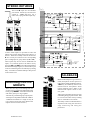
INTERNAL LINK OPTIONS
The console is set to satisfy most applications that should be encountered. However, the following internal
link options are offered to provide alternative settings for those applications that may require them. These
options involve resoldering of circuit board links and should only be carried out by competent technical
personnel. Further information is available in the GL3300 SERVICE MANUAL and from your agent.
MONO INPUT
1.
Reconfigure each aux as required to be
permanently pre-fade or post-fade rather than
switched by the front panel PRE/POST switch.
2.
Reconfigure the pre-fade sends to be postEQ / pre-mute, or pre-EQ / post-mute, instead
of the standard post-EQ / post-mute.
3.
Disable +48V phantom power regardless
of panel switch position - remove link.
4.
Reconfigure Direct Out to be pre-fader
instead of post fader.
STEREO INPUT
1.
Reconfigure each aux as required to be
permanently pre-fade or post-fade rather than
switched by the front panel PRE/POST switch.
2.
Reconfigure the pre-fade sends to be postEQ / pre-mute, or pre-EQ / post-mute, instead
of the standard post-EQ / post-mute.
3.
Disable +48V phantom power regardless
of panel switch position - remove link.
LEFT
1.
Reconfigure the LR sum source (mono)
from post LR faders to pre faders.
2.
Enable +48V phantom power to talkback
mic input - fit link.
GROUP
1.
Fit Matrix out balance option for jack
output tip = hot, ring = cold. Remove two links
and plug in balance driver IC.
2.
Reconfigure the feed to the optional VU
meterpod to follow the aux master rotary control
rather than the group fader - remove two resistors
and link two pairs of pads with a length of wire.
GL3300 USER GUIDE
19
MUTE GROUPS 1-4
AUX 1-8
GRP 1-8
LEFT
RIGHT
MTX A-B
PFL
AFL
AFL
AUX (1-4) MIX
AUX 1-4 OUT
AUX
INSERT
SL
BAL
2=+
-
-2dBu
+
+4dBu
PEAK
+6
0
SIGNAL
FADER
GROUP
INSERT
SL
POT
FADER
-2dBu
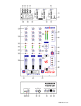
BLOCK DIAGRAM
G
+
GROUP (1-4) MIX
MTX A
MUTE
MTX B
AUX/GROUP REVERSE
AFL
SL
SYS-LINK WIRING POINT
G
MIC/
LINE
LINE IN
GROUP OUTPUT WIRING POINT
AUX (5-8) MIX
SL
FADER
LO-CUT
FILTER
L-R
MF1
PAN
EQ IN
MIC/LINE IN
+
2= +
3-4
GROUP (5-8) MIX
FADER
GROUP (AUX)
INSERT
SL
7-8
MUTE
+48V
2=+
+
FADER
MTX A
MUTE
MTX B
2
POST-EQ
RING = RETURN
3
POST-MUTE
AUX/GROUP REVERSE
4
AFL
VU
DIRECT OUT
PRE-FADE
PRE FADER
SUBGROUPING
METER SOURCE
SELECT
POT
PRE-MUTE
PRE-EQ
+4dBu
G
+
1
TIP = SEND
0dBu
-2dBu
GROUP (AUX) 5-8 OUT
BAL
POT
-2dBu
LF
IMPEDANCE
BALANCED
RING = PEAK
+6
0
SIGNAL
1-2
5-6
MF2
INSERT
AUX (GROUP) 5-8 OUT
TIP = +
-
GAIN
BAL
L-R
AFL
PFL
HF
-20dBu
PAN
FADER
PEAK
0dB
SIG
4-BAND 2-SWEEP
EQUALISER
SUBGROUPING
METER SOURCE
SELECT
POT
VU
PAN
L-R
FADER
POST-FADE
TIP = +
POST FADER
RING = -
0dBu
IMPEDANCE BALANCED
INTERNAL AUX LINK OPTIONS
AUX 1
PRE-FADE
SWITCHED
POST-FADE
PAN
1-2(3-4)
AUX 3
STEREO
RETURN
FADER
L-R
AUX 2
+
L/MONO
+
A-B
AUX 4
R
FADER
BAL OUT OPTION
MATRIX A(B) MIX
BAL
SL
POST
PRE
MATRIX A(B) OUT
+
-
0dBu
AUX 5
AFL
AUX 6
AUX 7
AUX 8
L FADER
POST
PRE
MTX A
SL
L MIX
MTX B
L INSERT
-
-20dBu
-2dBu
MTX A
PFL
GAIN
R MIX
FADER
MF1
L
BAL
EQ IN
+
L
RING = RETURN
0dBu
1-2
5-6
MF2
+48V
AUX1
7-8
MUTE
R
1
LF
L
AUX2
TB MIC IN
2
POST-EQ
LINE IN
-20dBu
AUX4
1
BAL
MIC/LINE IN
2= +
DIRECT OUT
PAD OPTIONS
R
R
PRE-FADE
R
2-TRK SEND
+
+
AUX8
+
+
SUM
INTERNAL AUX LINK OPTIONS
L-R/2TRK
AUX 1
PFL/AFL
L-R
AUX 2
AUX 3
PHONES LEV
-
HEADPHONES
L
R
2-TRK IN
L
-
+
AUX 4
MTR_L
R
+
MTR_R
POST
PRE
AUX 5
PAFL_DC
MTR_M
AUX 6
AFL MIX
MONO LEV
SL
TB DIM
AFL/PFL
AUX 7
AUX 8
POST
PRE
20
R
IMPEDANCE
BALANCED
RING = RETURN
POST-FADE
SWITCHED
PRE-FADE
L
-
4
POST-FADE
0dBu
L
AUX7
3
SUM
TIP = SEND
MONITOR METER
AUX6
2
L
+48V
LR SUM
R
POST-FADE
MUTE
GROUPS
AUX5
PRE-MUTE
PRE-EQ
POST-FADE
PRE-FADE
AUX3
TB LEV
3
POST-MUTE
4
GAIN
PRE-FADE
-
MONO R
MIC/
LINE
+4dBu
2=+
+
+
3-4
MONO L
TIP = SEND
R OUT
BAL
-2dBu
L-R
+48V
L INSERT
MTX B
R INSERT
-
MIC/LINE IN
R INSERT
R FADER
SL
HF
BAL
2= +
+4dBu
2=+
+
+
PEAK
0dB
SIG
4-BAND
EQUALISER
MIC/
LINE
LINE IN
L OUT
BAL
-2dBu
PFL MIX
SL
-8dBu
+
M OUT
BAL
+4dBu
2=+
-
+
LR SUM
-2dBu
PFL DC
AFL DC
GL3300 USER GUIDE