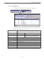
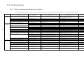
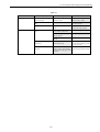
1
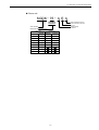
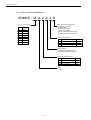
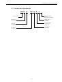
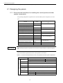
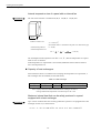
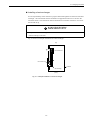
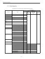
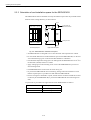
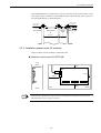
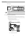
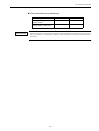
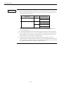
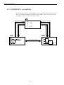
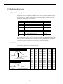
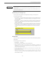
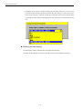
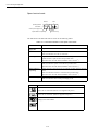
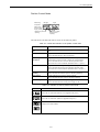
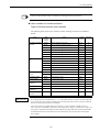
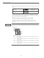
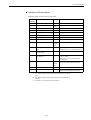
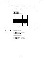
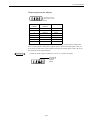
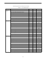
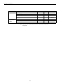
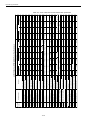
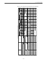
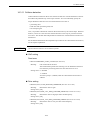
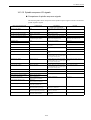
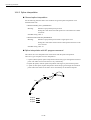
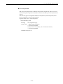
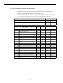
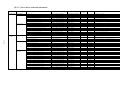
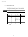
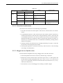
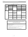
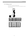
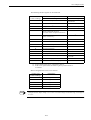
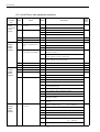
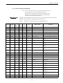
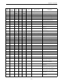
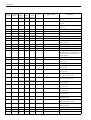
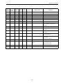
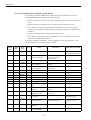
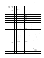
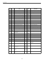
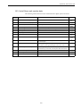
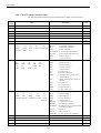
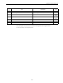
14.2 Servo control
14.2.14 Analog monitor
Each of the Servo drives and Spindle drives has an analog monitor function. You can
observe various waveforms using a measuring instrument, such as an oscilloscope, connected to a monitor cable from the CN16 (CN26 in the case of 2nd axis of the 2-axis-combined drive) of each unit.
Servo drive
• MD3003 (Pn003) FUNCTION_SWITCH_APPLIC3 (For each axis)
Meaning:
Function selection application switch 3
Initial value: 0002 (Monitor 1: Motor rotation speed; monitor 2: torque reference)
The following table shows a list of data that can be observed at a Servo drive and explains
how to set the magnification and others.
User
constant No.
MD3003
(Pn003)
Function
selection
application
Position
Name
Digit
position
Setting
0
Motor revolution speed: 1V/1000 min -1
1
Speed reference: 1V/1000 min -1
2
Torque reference: 1V/100%
3
Position deviation: 0.05 V/1 command unit
4
Position amplitude deviation: 0.05 V/1 command unit
5
Position command speed [min-1 conversion]: 1V/1000 min -1
6
Observer speed: 1V/1000 min -1
7
Collision detection amount: 1V/100%
8
Quadrant error compensation amount: 1V/100%
9
Speed feed forward: 1V/1000 min -1
A
Torque feed forward: 1V/100%
B
Model torque reference: 1V/100%
C
Model position deviation: 0.05 V/1 position unit
D
Estimated disturbance torque: 1V/100%
E
Vibration-damping monitor: 1V/1000 min -1
F
System constant data output
Digit 1
Digit 3
0
Multiplied by 1
1
Multiplied by 10
Magnification
2
Multiplied by 100
3
Multiplied by 1/10
4
Multiplied by 1/100
Lower
byte
Analog monitor 1
Digit 0
Upper
byte
Analog monitor 2
Digit 2
Signal
descriptions
Monitor 2
n
0
Monitor 1
0
0
CN2 signal
CN2 magnification
Description
0
CN2 signal
CN2 magnification
14-55
Factory
default
setting
0002