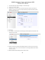
1
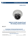
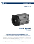
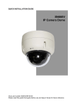
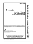
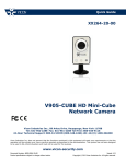
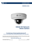
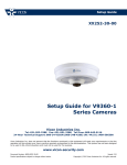
Installation Guide XX263-30-01 V9360W Outdoor Network Hemispheric Camera Vicon Industries Inc., 89 Arkay Drive, Hauppauge, New York 11788 Tel: 631-952-2288 Fax: 631-951-2288 Toll Free: 800-645-9116 24-Hour Technical Support: 800-34-VICON (800-348-4266) UK: 44/(0) 1489-566300 Vicon Industries Inc. does not warrant that the functions contained in this equipment will meet your requirements or that the operation will be entirely error free or perform precisely as described in the documentation. This system has not been designed to be used in life-critical situations and must not be used for this purpose. www.vicon-security.com Document Number: 8009-8263-30-01 Product specifications subject to change without notice. Issued: 613 Copyright © 2013 Vicon Industries Inc. All rights reserved. V9360W Hemispheric Camera with Advanced WDR Hardware User’s Manual Table of Contents 1. Precautions 3 Introduction 6 Package Contents............................................................................. 6 Features and Benefits .......................... Error! Bookmark not defined. Safety Instructions ............................... Error! Bookmark not defined. Physical description ......................................................................... 7 2. Installation Procedure 10 Connecting the IP Hemispheric Camera ....................................... 10 1) Remove the cover .............................................................. 10 2) Insert the cable ................................................................... 10 3) Connect cables to connectors ............................................ 10 How to Do the Waterproof Installation .......................................... 11 3. Accessing Camera 14 If you have DHCP server / router in your network: ...................... 14 If you do NOT have DHCP server / router in your network: ........ 14 2 V9360W Hemispheric Camera with Advanced WDR Hardware User’s Manual Precautions Read these instructions Read all the safety and operating instructions before using this product. Heed all warnings Adhere to all the warnings on the product and in the instruction manual. Failure to follow the safety instruction given may directly endanger people, cause damage to the system or to other equipment. Servicing Do not attempt to service this video device yourself as opening or removing covers may expose you to dangerous voltage or other hazards. Refer all servicing to qualified service personnel. Trademarks All names used in this manual are probably registered trademarks of respective companies. Liability Every reasonable care has been taken during the writing of this manual. Inform your local office if you find any inaccuracies or omissions. We cannot be held responsible for any typographical or technical errors and reserve the right to make changes to the product and manuals without prior notice. FCC/CE Regulation NOTE: This equipment has been tested and found to comply with the limits for a Class A digital device, pursuant to Part 15 of the FCC Rules. These limits are designed to provide reasonable protection against harmful interference when the equipment is operated in a commercial environment. This equipment generates, uses, and can radiate radio frequency energy and, if not installed and used in accordance with the instruction manual, may cause harmful interference to radio communications. Operation of this equipment in a residential area is likely to cause harmful interference in which case the users will be required to correct the interference at their own expense. 3 V9360W Hemispheric Camera with Advanced WDR Hardware User’s Manual Safety Instructions Don’t use the power supply with other voltages This device is likely to be damaged or damage other equipments/personnel, if you use a power supply with different voltage than the one included with this device. All warranty of this product will be voided if this occurs. Don’t open the housing of the product Cleaning Disconnect this video product from the power supply before cleaning. Attachments Do not use attachments not recommended by the video product manufacturer as they may cause hazards. Water and Moisture Do not use this video product near water, for example, near a bathtub, washbowl, kitchen sink, or laundry tub, in a wet basement, or near a swimming pool and the like. Don’t use accessories not recommended by the manufacturer Only install this device and the power supply in a dry place protected from weather Servicing Do not attempt to service this video product yourself, as opening or removing covers may expose you to dangerous voltage or other hazards. Refer all servicing to qualified service personnel. 4 V9360W Hemispheric Camera with Advanced WDR Hardware User’s Manual Damage Requiring service Disconnect this video product from the power supply immediately and refer servicing to qualified service personnel under the following conditions. 1) When the power-supply cord or plug is damaged 2) If liquid has been spilled, or objects have fallen into the video product. 3) If the video product has been directly exposed to rain or water. 4) If the video product does not operate normally by following the operating Instructions in this manual. Adjust only those controls that are covered by the instruction manual, as an improper adjustment of other controls may result in damage, and will often require extensive work by a qualified technician to restore the video product to its normal operation. Safety Check Upon completion of any service or repairs to this video product, ask the service technician to perform safety checks to determine if the video product is in proper operating condition. 5 V9360W Hemispheric Camera with Advanced WDR Hardware User’s Manual 1. Introduction Package Contents H.264 4-Megapixel IP D/N Outdoor Hemispheric Camera with Advanced WDR QIG Terminal Blocks for Power, DI/O, Audio Accessories Drill Template 6 V9360W Hemispheric Camera with Advanced WDR Hardware User’s Manual Physical Description 12 VDC Power Input Audio Input/Output Ethernet Port Digital Input/Output Reset Button Micro SDHC Card Slot Power Button 1) 12 VDC Power Input Connect DC power source to the terminal block. The wire with white dashed lines is the live wire, which should connect to the 12 V pin. PIN NAME DESCRIPTION 1 E-Ground Chassis Ground 2 GND 3 12 V DC Power Input 7 V9360W Hemispheric Camera with Advanced WDR Hardware User’s Manual 2) Ethernet Port The IP device connects to the Ethernet via a standard RJ-45 connector. Supporting NWAY, this IP device can auto detect the speed of local network segment (10Base-T/100Base-TX Ethernet). 3) Reset Button Step 1: Switch off IP device by disconnecting the power cable Step 2: Press and continue to hold the Reset Button (with a sharp tipped object, like a pen.) Step 3: Reconnect the power cable while continuing to hold the reset button. The red Power LED light will flash on for 3 second first, turn off for about 15 seconds, flash on for another second and turn off again. By this time the reset to default operation is already completed. This will take around 20 seconds from power up (this length of time fluctuates slightly with the environment). You may then release the Reset Button. The Power LED light will come back on and stay on after a few more seconds. The unit will start up with factory default settings automatically. Restore to Default Complete Power On On (3s) On 1s Off (about 15s) Off (10~15s) Stay On About 20 Seconds 4) Power Button Press the Power Button and the camera will reboot automatically. 5) Audio Input/Output The IP device supports audio input and output via terminal block. 6) Digital Input/Output Used in applications like motion detection, event triggering, time lapse recording, alarm notifications, etc., the I/O terminal connector provides the interface to: - Digital output (2) - For connecting external devices such as relays and LEDs. Connected devices can be activated by Output buttons on the Live View page or through video management software. Connect Pin 2 with Pin 4 or Pin 6 with Pin 8. 8 V9360W Hemispheric Camera with Advanced WDR Hardware User’s Manual - Digital Input (2) - An alarm input for connecting devices that can toggle between an open and closed circuit, for example: PIRs, door/window contacts, glass break detectors, etc. The device will detect the change in digital input and transmit the signal to video surveillance servers. Pin 1 GND Ground. Connect with Pin 3 for DI control loop. Pin 2 12 V Provides power to external devices with a Voltage: 12 VDC, maximum current of 100 mA. Max: 1.2 W Connect to GND (Pin 1) to activate or leave Must not be exposed floating (unconnected) to deactivate. to voltages greater Pin 3 Digital Input 1 than 30 VDC. Pin 4 Digital Connect to Pin 2 through external devices for Max load = <100 mA Output 1 DO loop. If used with an external relay, a diode Max voltage = 24 VDC must be connected in parallel with the load for (to the transistor) protection against transient voltages. Pin 5 GND Ground. Connect with Pin 7 for DI control loop. Pin 6 12 V Provides power to external devices with a Voltage: 12 VDC, maximum current of 100 mA. Max: 1.2 W Connect to GND (Pin 5) to activate or leave Must not be exposed floating (unconnected) to deactivate. to voltages greater Pin 7 Digital Input 2 than 30 VDC. Pin 8 Digital Connect to Pin 6 through external devices for Max load = <100 mA Output 2 DO loop. If used with an external relay, a diode Max voltage = 24 VDC must be connected in parallel with the load for (to the transistor) protection against transient voltages. Connect input/output devices to the camera as follows: 1. Attach the cables for the device securely to the supplied green connector block. 2. Once cables are connected, push connector block into the terminal connector on camera. Digital Input/Output Connector 7) Micro SDHC Card Slot* Insert a Micro SDHC card (*customer supplied) for local recording on camera. 9 V9360W Hemispheric Camera with Advanced WDR Hardware User’s Manual 2. Installation Procedure Connecting the IP Hemispheric Camera 1) Remove the cover Remove the dome cover with special hex wrench provided in the accessory kit. 2) Insert the cable There are two conduit holes on the hemispheric camera, one on the bottom and the other on the side. Remove the plug if the cable will be routed through the hole on the bottom of the hemispheric camera. Route the necessary cables to the installation site. 3) Connect cables to connectors Follow the instructions in the Physical Description section for how to connect each connector. 10 V9360W Hemispheric Camera with Advanced WDR Hardware User’s Manual How to Do the Waterproof Installation The following installation procedure assures the camera to be water-resistant, even in environments where the camera can easily be flooded by pouring rain. Important for the installation: The protection of the cabling must be done by a proper flex conduit. The size of the flex conduit that matches the conduit gland is is 3/8” (trade size) (customer-supplied; not included in the package). Insert the Ethernet cable through the flex conduit together with RJ-45 connector. As an alternative, connect the RJ-45 connector by crimping after pushing the cable through the conduit. Disassemble the conduit gland. Slide the clamping nut around flex conduit approximately 4-8 in. (100-200 mm) away from the top. Fit the sealing insert (made of rubber) to the top of the flex conduit. Select which of the 2 holes is going to be used to connect the flex conduit, the hole on the side or the hole on the bottom. Remember to seal off the hole not used with the metal patch (included in the camera accessories). Using the side hole Using the bottom hole 11 V9360W Hemispheric Camera with Advanced WDR Hardware User’s Manual Screw the body of the conduit gland into the camera and fix it with the lock nut (included with the customer-supplied conduit gland) from the inside of the camera. Connect the Ethernet cable to the camera’s network port. If you are not using PoE, pull the DC power cable through the flex conduit as well and connect to the camera at this point. Push the head of the flex conduit, wrapped with sealing insert, into the body of the conduit gland. Screw the clamping nut tightly onto the body of the conduit gland. 12 V9360W Hemispheric Camera with Advanced WDR Hardware User’s Manual Adjust the viewing angle and focus of the camera; reattach the dome cover and tighten using the screws. A fully waterproof installation is now complete. Using the V9360-WM Wall Mount If it is required to mount the V9360W to a wall, use the V9360-WM. Typical mounting hardware is provided; be sure to use mounting hardware appropriate for the mounting surface. 1. A mounting template is provided with the wall mount. Mark the mounting holes on the surface and drill mounting holes. Mount the flat side of the V9360-WM to the wall, with the wide end (with the cable hole) at the top, using appropriate hardware for the surface; be sure to use anchors as needed. Cables can be routed through the back slot or through the access hole. 2. Remove the camera cover if not already done. Align the three (3) holes on the bottom of the V9360W with the mounting posts of the V9360-WM. Secure with the screws provided. Reattach the cover. 13 V9360W Hemispheric Camera with Advanced WDR Hardware User’s Manual 3. Accessing Camera If you have DHCP server/router in your network: Many network server/routers are able to automatically provide IP addresses through DHCP. If you have DHCP on the network, just plug in your computer and IP Hemispheric Camera into the network and your IP device will acquire a network address by itself. Find and access the device with the IP Utility program. If you do NOT have DHCP server/router in your network: 1. Configure your PC to use the same subnet by changing your PC’s IP address to the subnet with prefix 192.168.0.XXX. The last number should be anything from 1 to 254 except 100 or other used IP addresses. Subnet mask should be 255.555.255.0. 2. The default IP used by this device is 192.168.0.100. Make sure your PC is NOT using this address and that no two devices use the same IP address in the network. 3. Change your IP address by going to Control Panel ->Manage Network Connections ->. Right click on the connection to change -> Option -> TCP/IP IPv4 Properties. Enter the settings as below. IP address: 192.168. 0.xxx Subnet mask: 255.255.255.0 NOTE: xxx should be a number from 1 to 254 except 100, which is used by the IP device. Make sure that no two devices use the same IP address in the same network. 4. Open Internet Explorer (Version 8.0 or above) , and type in the Default IP: 192.168.0.100 14 V9360W Hemispheric Camera with Advanced WDR Hardware User’s Manual 5. When the login window displays, input default user and password: Default User: Admin Password: 123456 6. After logging in, the Live View will display. To go to the main menu, click the ”Setup” button on the top left. If there is only a single camera, the procedure is complete to access the device. If there are multiple devices in the system, you need to change the current device to another unused IP address, so that when the next device is connected to the network, no two devices use the same IP. Perform the following steps. 15 V9360W Hemispheric Camera with Advanced WDR Hardware User’s Manual 7. From the Setup Page, select IP Settings -> Connection Type. 8. Change the IP mode to Static. 9. Change the IP to 192.168.0.102 or any other unused IPs. Do NOT use the PC’s IP address or 192.168.0.100. If this is not the first device you add to the network, please also avoid other devices’ IPs. 10. Click Apply. 11. Go to System -> Save & Reboot, and click Apply. Internet Explorer will close after a few seconds. This is normal. 12. Wait for 30 seconds and open Internet Explorer again to connect to the new IP (in this example, 192.168.0.101). For the second device or more being added into the network, enter the correct IP. 13. Adjust the default Video setting by going to Video & Audio. 16 Shipping Instructions Use the following procedure when returning a unit to the factory: 1. Call or write Vicon for a Return Authorization (R.A.) at one of the locations listed below. Record the name of the Vicon employee who issued the R.A. Vicon Industries Inc. 89 Arkay Drive Hauppauge, NY 11788 Phone: 631-952-2288; Toll-Free: 1-800-645-9116; Fax: 631-951-2288 For service or returns from countries in Europe, contact: Vicon Industries (U.K.) Ltd Brunel Way Fareham, PO15 5TX United Kingdom Phone: +44 (0)1489/566300; Fax: +44 (0)1489/566322 2. Attach a sheet of paper to the unit with the following information: a. Name and address of the company returning the unit b. Name of the Vicon employee who issued the R.A. c. R. A. number d. Brief description of the installation e. Complete description of the problem and circumstances under which it occurs f. Unit’s original date of purchase, if still under warranty 3. Pack the unit carefully. Use the original shipping carton or its equivalent for maximum protection. 4. Mark the R.A. number on the outside of the carton on the shipping label. Vicon Standard Equipment Warranty Vicon Industries Inc. (the “Company”) warrants your equipment to be free from defects in material and workmanship under Normal Use from the date of original retail purchase for a period of three years, with the following exceptions: 1. 2. 3. 4. 5. 6. 7. 8. Monitors, all models: One year from date of original retail purchase. Uninterruptible Power Supplies: Two years from date of original retail purchase. VDR-700 Recorder Series: One year from date of original retail purchase. V5616MUX: One year from date of original retail purchase. Arecont Cameras: One year from date of original retail purchase. FMC series fiber-optic media converters and associated accessories: Lifetime warranty. For PTZ cameras, “Normal Use” excludes prolonged use of lens and pan-and-tilt motors, gear heads, and gears due to continuous use of “autopan” or “tour” modes of operation. Such continuous operation is outside the scope of this warranty. Any product sold as “special” or not listed in Vicon’s commercial price list: One year from date of original retail purchase. Date of retail purchase is the date original end-user takes possession of the equipment, or, at the sole discretion of the Company, the date the equipment first becomes operational by the original end-user. The sole remedy under this Warranty is that defective equipment be repaired or (at the Company’s option) replaced, at Company repair centers, provided the equipment has been authorized for return by the Company, and the return shipment is prepaid in accordance with policy. The Company will not be obligated to repair or replace equipment showing abuse or damage, or to parts which in the judgment of the Company are not defective, or any equipment which may have been tampered with, altered, misused, or been subject to unauthorized repair. Software supplied either separately or in hardware is furnished on an “As Is” basis. Vicon does not warrant that such software shall be error (bug) free. Software support via telephone, if provided at no cost, may be discontinued at any time without notice at Vicon’s sole discretion. Vicon reserves the right to make changes to its software in any of its products at any time and without notice. This Warranty is in lieu of all other conditions and warranties express or implied as to the Goods, including any warranty of merchantability or fitness and the remedy specified in this Warranty is in lieu of all other remedies available to the Purchaser. No one is authorized to assume any liability on behalf of the Company, or impose any obligations on it in connection with the sale of any Goods, other than that which is specified above. In no event will the Company be liable for indirect, special, incidental, consequential, or other damages, whether arising from interrupted equipment operation, loss of data, replacement of equipment or software, costs or repairs undertaken by the Purchaser, or other causes. This warranty applies to all sales made by the Company or its dealers and shall be governed by the laws of New York State without regard to its conflict of laws principles. This Warranty shall be enforceable against the Company only in the courts located in the State of New York. The form of this Warranty is effective May 4, 2012. THE TERMS OF THIS WARRANTY APPLY ONLY TO SALES MADE WHILE THIS WARRANTY IS IN EFFECT. THIS WARRANTY SHALL BE OF NO EFFECT IF AT THE TIME OF SALE A DIFFERENT WARRANTY IS POSTED ON THE COMPANY’S WEBSITE, WWW.VICON-SECURITY.COM. IN THAT EVENT, THE TERMS OF THE POSTED WARRANTY SHALL APPLY EXCLUSIVELY. Vicon Part Number: 8006-9010-03-10 Rev 0512 Vicon Industries Inc. Corporate Headquarters 89 Arkay Drive Hauppauge, New York 11788 631-952-2288 800-645-9116 Fax: 631-951-2288 Vicon Europe Headquarters Brunel Way Fareham, PO15 5TX United Kingdom +44 (0) 1489 566300 Fax: +44 (0) 1489 566322 Vicon Germany Kornstieg 3 D-24537 Neumuenster Phone: +49 (0) 4321 8790 Fax: +49 (0) 4321 879 97 Far East Office Unit 5, 17/F, Metropole Square 2 On Yiu Street, Shatin New Territories, Hong Kong (852) 2145-7118 Fax: (852) 2145-7117 Internet Address: www.vicon-security.com