1
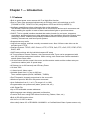
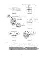
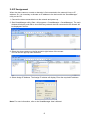
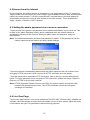
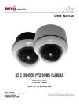
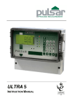
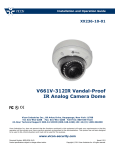
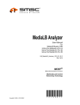
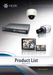
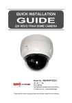
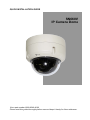
QUICK INSTALLATION GUIDE
SN660V
IP Camera Dome
Vicon part number 8009-8249-40-00
Please read this guide thoroughly before use and keep it handy for future reference.
Chapter 1 — Introduction
1.1 Features
• Built-in optical power zoom camera with True Night Shot function
• Dual or Triple video streams simultaneously at full frame rate in all resolutions up to D1
(720X480 in NTSC, 720X576 in PAL) using Motion JPEG and H.264 (or MPEG-4)
• Intelligent capabilities such as enhanced video motion detection
The encoder’s external inputs and outputs can be connected to devices such as sensors and
relays, enabling the system to react to alarms and activate lights or open/close doors.
• ONVIF: This is a global interface standard that makes it easier for end users, integrators,
consultants, and manufacturers to take advantage of the possibilities offered by network video
technology. ONVIF enables interoperability between different vendor products, increased
flexibility, reduced cost, and future-proof systems.
• Supports two-way audio
• Logs all user access, and lists currently connected users. Also, full frame rate video can be
provided over HTTPS.
• Interface Protocol: TCP/IP, UDP, IPv4/v6, HTTP, HTTPS, QoS, FTP, uPnP, RTP, RTSP, RTCP,
DHCP, ARP
• 240 Preset positions with the individual camera AE setup
• 8 Tours consist of Presets, Patterns, Auto Scans and other Tours can be programmed with
over 300 functions and preset locations. While moving, each Preset scan can be watched in
smooth Vector Scan mode.
• 16 Auto Scans with the normal, the vector, and the random mode and the endless auto-pan
(continuous rotation) with 13 speed steps
• 8 Patterns (up to 200 second) and 8 Privacy Zones
• 16 Area Titles
• 1 Alarm input/1 Alarm output
• Variable speed from 0.1°/sec to 380°/sec
Three variable speeds (SLOW, NORMAL, TURBO)
• Pan/Tilt speed is inversely proportional to the zoom ratio.
• Maximum speed is 380°/sec with preset command.
• Auto Calibration from 0.1° to 6° (Tilt range is 0° to 180°)
• Programmable user preferences (alarm, preset, title, etc.)
• 180° Digital Flip
• Up to 255 selectable camera addresses
• Multi-language menu display; password confirmation
• Function Run menu using DVR without function key (Pattern, Scan, etc.)
• Built-in RS-485 receiver driver
• 24 VAC or 12 VDC for dome
• Use satisfy clause 2.5 of IEC60950-1/UL60950-1 or Certified/Listed Class 2 power source only.
2
Chapter 2 — Installation and Configuration
2.1 Package Contents
The dome camera is designed with a compact, small size, hard dome camera housing.
The housing is constructed of aluminum, steel and plastic. The housing is designed to be
mounted on a wall or a ceiling. The housing meets the Protection Classification IP66 standards
for dust and moisture resistance.
* Dome Camera
* Installation Guide/CD
* Template Sheet
* Mounting Bracket
* Safety Lanyard
* Accessory Kit
1) Mounting screws (PH6 x 35.0)
2) Plastic anchors
3) O-Rings
4) Torx wrench
* Accessory Connector
1) 3-Pin Terminal Block
2) 6-Pin Terminal Block
1
1
1
1
1
1
(4)
(4)
(4)
(1)
1
(1)
(1)
3
2.2 Installation
The dome camera is for use in surface or pendant mounting applications, and the mounting
surface must be capable of supporting loads of up to 3.5 lb (1.6 kg). (Pendant mounting must use
pendant mount accessory.)
The dome camera’s mounting bracket should be attached to a structural object, such as hard
wood, wall stud or ceiling rafter, that supports the weight of the dome camera.
CAUTION: A silicone rubber sealant must be applied to seal the housing to secure
waterproofing.
2.2.1 Locking Dome Camera – refer to the Figures that follow
A. Make screw holes on the ceiling using the supplied mounting Template Sheet (Figure A).
B. Fix the Mounting Bracket to the ceiling using supplied Anchors (4x) and Mounting Screws (4x)
(Figure B).
C. Hook the Safety Lanyard to the Safety Lanyard Hook of the Mounting Bracket (Figure C).
D. Align the locking tab on the bracket and the locking slot on the base of the dome (Figure D).
E. Turn the dome counterclockwise about 10 degrees to the locked position (Figure E).
4
CAUTION: Before installing mounting bracket to surface, pre-adjust the four mounting
screws "A" on the base of the dome camera to best match the mounting
bracket locked position. Unscrew the locking screw on the side of the dome's
base and fit the tab of the mounting bracket into the locking slot. Screws "A"
should not be too tight or too loose when the dome is in the locked position.
After setting the proper positions of screws "A" remove the mounting bracket
and install it to the proper surface. If it is too difficult to lock the dome in
position after the mounting bracket has been installed readjust the screws "A"
by unscrewing them a small amount and try to install dome camera again.
5
2.3 Basic Configuration of Dome Camera System
No.
Wire Color
Description
1
Red: 24 VAC or 12 VDC+
White: 24 VAC or 12 VDC-
Main Power: 3-Pin terminal
2
Black: GND
Gray: Alarm Input
Yellow: GND
Black&White: Alarm Output
Green: RS485+
Blue: RS485-
Alarm Input/Output, RS485: 6-Pin terminal
3
Black
Ethernet: RJ45 Modular Jack
4
BNC Black
Video Composite Output: BNC Jack
5
RCA Gray
Audio line output: RCA Jack
6
RCA Black
Audio line input: RCA Jack
The dome camera must be installed by qualified service personnel in accordance with all local
and federal electrical and building codes.
6
2.4 Setting Dome Camera Address (ID)
To prevent damage, each dome camera must have a unique address (ID).
When installing multiple dome cameras using a multiplexer, it is suggested that the dome camera
address match the multiplexer port number.
The factory default setting is 1.
2.5 Connections
• Connecting to the RJ-45
Connect a standard RJ-45 cable to the network port of the dome camera. Generally a crossover cable is used for directly connection to PC, while a direct cable is used for connection to a
hub.
• Connecting Alarms
AI (Alarm Input)
You can use external devices to signal the dome camera to react on events. Mechanical or
electrical switches can be wired to the AI (Alarm Input) and G (Ground) connectors.
G (Ground)
NOTE: All the connectors marked G or GND are common.
Connect the ground side of the alarm input and/or alarm output to the G (Ground) connector.
AO (Alarm Output)
The dome camera can activate external devices such as buzzers or lights. Connect the device
to the AO (Alarm Output) and G (Ground) connectors.
• Connecting to the RS485
The dome camera can be controlled remotely by an external device or control system, such as
a control keyboard, using RS485 half-duplex serial communications signals.
• Connecting Video Output connector
Connect the video output (BNC) connector to the monitor or video input.
• Connecting the Power
Connect the power of 24 VAC or 12 VDC 1A for the dome camera.
When using a 12 VDC adapter, connect the positive (+) pole to the “+” position and
the negative (-) pole to the “-” position.
Use satisfy clause 2.5 of IEC60950-1/UL60950-1 or Certified/Listed Class 2 power source only.
7
2.6 IP Assignment
When the dome camera, encoder or decoder is first connected to the network it has no IP
address. So, it is necessary to allocate an IP address to the device with the “SmartManager”
utility on the CD.
1. Connect the dome camera/device to the network and power up.
2. Start SmartManager utility (Start > All programs > SmartManager > SmartManager). The main
window will display, and after a short while any network devices connected to the network will
be displayed in the list.
3. Select the dome camera on the list and click right button of the mouse.
You can see the pop-up menu as below.
4. Select Assign IP Address. The Assign IP window will display. Enter the required IP address.
Note: For more information, refer to the SmartManager User’s Manual.
8
2.7 Getting Started
Once installed apply power to the dome camera. The dome camera will start a configuration
sequence.
AREA TITLE
FUNCTION TITLE
INFORMATION
DISPLAY
ABC
001
AF AE
STATUS of
FOCUS and AE
CAMERA TITLE
EMPTY DATA
CAMERA ID
DOMEID:001
W→360.0 090.0
PAN & TILT ANGLE
VIEW DIRECTION
OSD Position
The dome can move the OSD position in the OSD position setup.
(AREA TITLE)
(FUNC TITLE )
(AF AE)
(CTRL KEY TO MOVE)
SAVE AND EXIT(ESC TO CANCEL)
(DOME ID…)
(ANGLE…)
OSD Position Setup
9
Chapter 3 — Program and Operation
Note: The use of certain keypads may limit the functionality of the unit, for example the number
of available presets or patterns.
3.1 Dome Camera Selection
Before you program or operate a dome camera, you must select the dome camera by pressing
No. + CAM keys.
Example: Pressing 1 , 0 + CAM keys sequentially will select dome camera 10. The selected
dome camera ID will be displayed on the LCD monitor of the keyboard controller.
3.2 Accessing the On-Screen Menu Utility
You can call up the On-screen menu utility (OSD) on your monitor by pressing the P95P key on
the keyboard controller; the following on-screen menu utility will appear:
Note: Throughout this manual, P**P (where ** is the Preset number) means pressing the Preset
key, entering the Preset number and then pressing the Preset key again.
DOME MENU
AUTO SCAN
PRESET
TOUR
PATTERN
AREA TITLE
PRIVACY ZONE
CAMERA
DOME SETUP
DOME COMMUNICATION
FUNCTION RUN
EXIT(ESC TO EXIT)
3.3 How to control the On-Screen Menu Utility
Function
Button
P95P
Call the On-screen menu utility.
Joystick up or down
Navigate through the menu items.
Go into the sub-menu items.
Joystick left or right or Open IRIS
Change value.
Enter the editing title mode.
Joystick left or right or
ZOOM In , ZOOM Out
Open IRIS + Joystick
Change value of angle.
Enter the changing angle mode.
Open IRIS
Exit the changing angle mode.
Close IRIS
P96P
Escape (EXIT)
10
Chapter 4 — Operation by Web Browser
The network camera can be used with Windows® operating system and browsers.
The recommended browsers are Internet Explorer®, Safari®, Firefox®, Opera™ and Google®
Chrome® with Windows.
Note: To view streaming video in Microsoft Internet Explorer, set your browser to allow ActiveX
controls.
4.1 Access from a browser
1) Start a browser (Internet Explorer).
2) Enter the IP address or host name of the network camera in the Location/Address field of
your browser.
3) You can see a starting page. Click Live View, Playback or Setup to enter web page.
4) The encoder’s Live View page appears in your browser.
11
4.2 Access from the internet
Once connected, the network camera is accessible on your local network (LAN). To access the
video encoder from the Internet you must configure your broadband router to allow incoming data
traffic to the video encoder. To do this, enable the NAT traversal feature, which will attempt to
automatically configure the router to allow access to the video encoder. This is enabled from
Setup > System > Network > NAT Traversal.
4.3 Setting the admin password over a secure connection
To gain access to the product, the password for the default administrator user must be set. This
is done in the “Admin Password” dialog, which is displayed when the network camera is
accessed for the setup at the first time. Enter your admin name and password, set by the
administrator.
Note: The default administrator username and password is “admin”. If the password is lost, the
network camera must be reset to the factory default settings.
To prevent network eavesdropping when setting the admin password, this can be done via an
encrypted HTTPS connection, which requires an HTTPS certificate (see note below).
To set the password via a standard HTTP connection, enter it directly in the first dialog shown
below. To set the password via an encrypted HTTPS connection, please see Setup > System >
Security > HTTPS in the full User's manual.
Note: HTTPS (Hypertext Transfer Protocol over SSL) is a protocol used to encrypt the traffic
between web browsers and servers. The HTTPS certificate controls the encrypted
exchange of information.
4.4 Live View Page
The live view page comes in four screen modes like 704x576 (480), 352x288 (240), 640x480 and
320x240. Users are allowed to select the most suitable one out of those modes. Adjust the mode
in accordance with your PC specifications and monitoring purposes.
12
1) General controls
The video drop-down list allows you to select a customized or preprogrammed video stream on the live view page. Stream profiles are
configured under Setup > Basic Configuration > Video & Image.
Please see “4.5.1 Basic Configuration” in the full User's manual for more
information.
The resolution drop-down list allows you to select the most suitable one
out of video resolutions to be displayed on live view page.
The protocol drop-down list allows you to select which combination of
protocols and methods to use depending on your viewing requirements,
and on the properties of your network.
The preset drop-down list allows you to select the preset number for the
PTZ camera being used. This icon is inactivated if the PTZ settings are not
set.
2) Control toolbar
The live viewer toolbar is available in the web browser page only. It displays the following
buttons:
The Stop button stops the video stream being played. Pressing the key again toggles
the start and stop. The Start button connects to the network camera or starts playing a
video stream.
The Pause button pauses the video stream being played.
The Snapshot button takes a snapshot of the current image. The location where the
image is saved can be specified.
The digital zoom activates a zoom-in or zoom-out function for video image on the live
screen.
The Full Screen button causes the video image to fill the entire screen area. No other
windows will be visible. Press the 'Esc' button on the computer keyboard to cancel full
screen view.
The Manual Trigger button activates a pop-up window to manually start or stop the
event.
The PTZ button activates a pop-up window for Pan, Tilt and Zoom control.
Use this scale to control the volume of the speakers.
13
Use this scale to control the volume of the microphone.
Use this scale to control the volume of the speakers and microphones.
3) Camera Menu controls
If the network camera has been appropriately configured, the Live View page displays the
controls available for the OSD menu.
4) Pan/Tilt/Zoom controls
If the network camera has been appropriately configured, the Live View page displays the
controls available for the PTZ (Pan/Tilt/Zoom) or PT device installed. The administrator can
enable/disable the controls for specified users.
5) Video and Audio Streams
The network camera provides several images and video stream formats. Your requirements
and the properties of your network will determine the type you use.
The Live View page in the network camera provides access to H.264, MPEG-4 and Motion
JPEG video streams, and to the list of available video streams. Other applications and
clients can also access these video streams/images directly, without going via the Live View
page.
4.5 Network Camera Setup
This section describes how to configure the network camera, and is intended for product
Administrators, who have unrestricted access to all the Setup tools; and Operators, who have
access to the settings for Basic, Live View, Video & Image, Audio, Event, and System
Configuration.
You can configure the network camera by clicking Setup in the top right-hand corner of the Live
View page. Click on this page to access the online help that explains the setup tools.
When accessing the network camera for the first time, the “Admin Password” dialog appears.
Enter your admin name and password, set by the administrator.
Note: If the password is lost, the network camera must be reset to the factory default settings.
14
4.6 Resetting to the factory default settings
To reset the network camera to the original factory settings, go to the Setup > System >
Maintenance web page or use the control button on the network camera, as described below:
• Using the Reset Button
Follow the instructions below to reset the network camera to the factory default settings
using the Reset Button.
1. Switch off the network camera by disconnecting the power adapter.
2. Open the lens cover.
3. Press and hold the Control Button (SW1) on the board with your finger while reconnecting
the power.
4. Keep the Control button (SW1) pressed for about 2 seconds.
5. Release the Control Button (SW1).
6. The network camera resets to factory defaults and restarts after completing the factory
reset.
7. Close the lens cover.
CAUTION: When performing a Factory Reset, you will lose any settings that have been saved.
4.7 System Requirement for Web Browser
Operating System: Microsoft Windows 98, Microsoft Windows ME, Microsoft Windows 2000,
Microsoft Windows XP, or Microsoft Windows Vista
CPU: Over Pentium® IV 2.4Ghz, 512MB RAM, 10GB free disk or higher
VGA: AGP, Video RAM 32MB or higher (1024x768, 24bpp or higher)
4.8 More Information
For more information, please see the Network Camera User’s Manual, which is available on the
CD included in this package.
Microsoft, Windows and Internet Explorer are registered trademarks of Microsoft Corporation. Safari is a
registered trademark of Apple Inc. Chrome is a registered trademark of Google; Firefox is a registered
trademark of Mozilla Corp. Opera is a trademark of Opera Software ASA. Pentium is a registered
trademark of Intel Corporation.
15
Vicon Industries Inc.
Corporate Headquarters
89 Arkay Drive
Hauppauge, New York 11788
631-952-2288 800-645-9116
Fax: 631-951-2288
Vicon Europe
Headquarters
Brunel Way
Fareham, PO15 5TX
United Kingdom
+44 (0) 1489 566300
Fax: +44 (0) 1489 566322
Vicon Germany
Kornstieg 3
D-24537 Neumuenster
Phone: +49 (0) 4321 8790
Fax: +49 (0) 4321 879 97
Far East Office
Unit 5, 17/F, Metropole Square
2 On Yiu Street, Shatin
New Territories,
Hong Kong
(852) 2145-7118
Fax: (852) 2145-7117
Internet Address: www.vicon-security.com
SN660V IP Camera Dome
Printed in Korea
50303267A