1
ADC12D1800RF
www.ti.com
6.2.1.4
SNAS518I – JULY 2011 – REVISED JANUARY 2014
Calibration Pin (CAL)
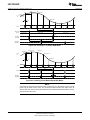
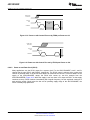
The Calibration (CAL) Pin may be used to execute an on-command calibration or to disable the power-on
calibration. The effect of calibration is to maximize the dynamic performance. To initiate an on-command
calibration via the CAL pin, bring the CAL pin high for a minimum of tCAL_H input clock cycles after it has
been low for a minimum of tCAL_L input clock cycles. Holding the CAL pin high upon power-on will prevent
execution of the power-on calibration. In ECM, this pin remains active and is logically OR'd with the CAL
bit.
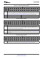
To use this feature in ECM, use the CAL bit in the Configuration Register (Addr: 0h; Bit: 15). See
Calibration Feature for more information.
6.2.1.5
Calibration Delay Pin (CalDly)
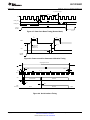
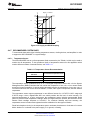
The Calibration Delay (CalDly) Pin selects whether a shorter or longer delay time is present, after the
application of power, until the start of the power-on calibration. The actual delay time is specified as tCalDly
and may be found in Converter Electrical Characteristics Calibration. This feature is pin-controlled only
and remains active in ECM. It is recommended to select the desired delay time prior to power-on and not
dynamically alter this selection.
See Calibration Feature for more information.
6.2.1.6
Power Down I-channel Pin (PDI)
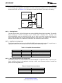
The Power Down I-channel (PDI) Pin selects whether the I-channel is powered down (logic-high) or active
(logic-low). The digital data output pins, DI and DId, (both positive and negative) are put into a high
impedance state when the I-channel is powered down. Upon return to the active state, the pipeline will
contain meaningless information and must be flushed. The supply currents (typicals and limits) are
available for the I-channel powered down or active and may be found in Converter Electrical
Characteristics Power Supply Characteristics. The device should be recalibrated following a power-cycle
of PDI (or PDQ).
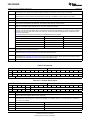
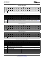
This pin remains active in ECM. In ECM, either this pin or the PDI bit (Addr: 0h; Bit: 11) in the Control
Register may be used to power-down the I-channel. See Power Down for more information.
6.2.1.7
Power Down Q-channel Pin (PDQ)
The Power Down Q-channel (PDQ) Pin selects whether the Q-channel is powered down (logic-high) or
active (logic-low). This pin functions similarly to the PDI pin, except that it applies to the Q-channel. The
PDI and PDQ pins function independently of each other to control whether each I- or Q-channel is
powered down or active.
This pin remains active in ECM. In ECM, either this pin or the PDQ bit (Addr: 0h; Bit: 10) in the Control
Register may be used to power-down the Q-channel. See Power Down for more information.
6.2.1.8
Test Pattern Mode Pin (TPM)
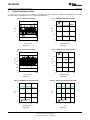
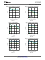
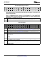
The Test Pattern Mode (TPM) Pin selects whether the output of the ADC12D1800RF is a test pattern
(logic-high) or the converted analog input (logic-low). The ADC12D1800RF can provide a test pattern at
the four output buses independently of the input signal to aid in system debug. In TPM, the ADC is
disengaged and a test pattern generator is connected to the outputs, including ORI and ORQ. See Test
Pattern Mode for more information.
6.2.1.9
Full-Scale Input Range Pin (FSR)
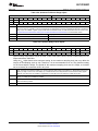
The Full-Scale Input Range (FSR) Pin sets the full-scale input range for both the I- and Q-channel; for the
ADC12D1800RF, only the logic-high setting is available. The input full-scale range is specified as VIN_FSR
in Converter Electrical Characteristics Analog Input / Output and Reference Characteristics. In Non-ECM,
the full-scale input range for each I- and Q-channel may not be set independently, but it is possible to do
so in ECM. The device must be calibrated following a change in FSR to obtain optimal performance.
Functional Description
Copyright © 2011–2014, Texas Instruments Incorporated
Submit Documentation Feedback
Product Folder Links: ADC12D1800RF
43