1
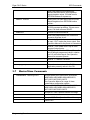
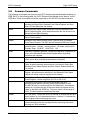
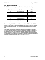
CW-P SERIES
PROGRAMMABLE
AC POWER SOURCE
Programming Manual
This manual covers models:
CW 801P
CW 1251P
CW 2501P
Contact Information
Telephone: 800 733 5427 (toll free in North America)
858 450 0085 (direct)
Fax: 858 458 0267
Email:
Domestic Sales: [email protected]
International Sales: [email protected]
Customer Service: [email protected]
Web: www.programmablepower.com
March 2011
Document No. M161691-03 Rev E
Contents
Elgar CW-P Series
CONTENTS
SECTION 1 SCPI CONFORMANCE INFORMATION ........................... 1-1
1.1
Introduction ........................................................................................... 1-1
1.2
Parameter Definitions ........................................................................... 1-1
1.3
Units ...................................................................................................... 1-1
1.4
Conventions .......................................................................................... 1-2
1.5
Queries ................................................................................................. 1-2
SECTION 2 POWER-ON AND RESET CONDITIONS .......................... 2-1
2.1
Factory Defaults .................................................................................... 2-1
2.2
Power-On Conditions ............................................................................ 2-1
2.3
Reset Conditions ................................................................................... 2-2
2.4
Changing Voltage Ranges Via Command Interface ............................. 2-2
2.5
Changing Ranges During Recall Via Command Interface .................... 2-2
SECTION 3 SCPI COMMANDS ........................................................... 3-1
3.1
Miscellaneous Commands .................................................................... 3-1
3.2
MEASURE Commands ......................................................................... 3-1
3.3
OUTPUT Commands ............................................................................ 3-2
3.4
SOURCE Commands ........................................................................... 3-2
3.5
STATUS Commands ............................................................................ 3-4
3.6
SYSTEM Commands ............................................................................ 3-4
3.7
Master/Slave Commands ...................................................................... 3-5
3.8
Common Commands ............................................................................ 3-6
Programming Manual
i
Elgar CW-P Series
Contents
SECTION 4 RS-232 INTERFACE ......................................................... 4-1
4.1
RS-232 Interface Operation ................................................................. 4-1
4.2
RS-232 Characteristics......................................................................... 4-1
4.3
RS-232 Connector ................................................................................ 4-2
APPENDIX A: STATUS REGISTER DEFINITIONS ........................... A-1
A.1 Status Byte ........................................................................................... A-1
A.2 Standard Event Status Register ........................................................... A-2
A.3 Operation Status / Questionable Status Registers ................................ A-3
A.4 Error / Event Queue .............................................................................. A-3
A.5 Serial Poll Operation............................................................................. A-3
APPENDIX B: ERROR CODES ............................................................ B-1
B.1 Error Codes Returned by SYSTem:ERRor? Query .............................. B-1
B.2 SCPI Error Codes ................................................................................. B-1
APPENDIX C: SAMPLE PROGRAMS .................................................. C-1
ii
Programming Manual
SECTION 1
SCPI CONFORMANCE INFORMATION
1.1
Introduction
This manual provides programming information for Elgar‟s ContinuousWave™ series
programmable AC power sources. This manual is to be used in conjunction with the
CW-P Series Programmable AC Power Source Operation Manual (Elgar Document
No. M161691-01).
The CW-P Series power sources conform to all specifications for devices as defined in
IEEE 488.2, and comply with SCPI command syntax version 1995.0.
1.2
Parameter Definitions
Type
<boolean>
1.3
Valid Arguments
ON, OFF, 0, or 1, HIgh, LOw
<value>
Integer or Floating point number
<name>
String enclosed by single or double quotes
Units
The CW Series accepts the following units as suffixes to numeric values:
Type of Unit
Valid Suffix
Voltage
“Volts” or “V”
Current
“Amps” or “A”
Frequency
Time
Programming Manual
“Hz”
“ms” (milliseconds), “s” (seconds), or “min” (minutes)
1-1
SCPI Conformance Information
1.4
Elgar CW-P Series
Conventions
Commands enclosed by “[ ]” are optional.
For example, SOURce:VOLTage:LEVel:IMMediate:AMPLitude 120.0
can be written as, SOURce:VOLTage 120.0.
1.5
Queries
The query syntax is identical to the command syntax, with a ”?” appended.
For example, to query the programmed voltage on phase A, send the string:
SOURce:VOLTage?
A subsequent device read will return a value such as “120.00”. All queries are
terminated with a carriage return and line feed (0x0D 0x0A) for those GPIB controllers
that require termination characters. When the CW unit has nothing to report, its output
buffer will contain three ASCII characters: space, carriage return, and linefeed (in
decimal these values are <32><13><10>).
1-2
Programming Manual
SECTION 2
POWER-ON AND RESET CONDITIONS
The following sections define the factory and reset power-on conditions of the unit.
2.1
Factory Defaults
When the CW-P unit is first powered up, the following factory defaults will be in place:
GPIB Address:
25
RS-232 Baud Rate:
9600
RS-232 Data Bits:
8
RS-232 Stop Bits:
1
RS-232 Parity:
N
2.2
Power-On Conditions
When the CW-P unit is first powered up, the system reads in the configuration that was
last saved to memory position 0. The specific system items in Save and Recall are:
VoltsA, VoltsB, VoltsC (B and C for multi-unit configuration)
Voltage Range, either High or Low
Current Protection Type, either Fold or Shut
Current Shutdown Time
Current LimitA, Current LimitB, Current LimitC (B and C for multi-unit configuration)
Frequency
Phase AngleAB
Phase AngleAC
External Input Assignment, either Analog In or Pulse Out.
Programming Manual
2-1
Power-On and Reset Conditions
Elgar CW-P Series
In addition, unique system settings are read in from the non-volatile EEROM memory:
Output Relay State, either Auto Start or Standby
Keyboard Lock State, either Front Panel Program Enabled or Disabled
Master/Slave status if part of a multi-unit configuration
2.3
Reset Conditions
When the *RST command is sent via SCPI, the following conditions apply:
Faults are cleared
The error queue is cleared
The output relay is opened
VoltsA, VoltsB, VoltsC are set to 0
A locked keyboard remains locked.
2.4
Changing Voltage Ranges Via Command Interface
When the voltage range is changed using the command interface:
SOUR:VOLT:RANGE 1
If moving from low range to high range, and the output relay was initially in the closed
state, the CW will open the output relay. In this case, the programmer must re-close the
relay and set the new voltage.
2.5
Changing Ranges During Recall Via Command
Interface
Assume that the CW is in low range with the output relay closed and sourcing 100 volts.
If a recall is performed:
SYST:RECALL 33
And the recalled system state was initially saved in high range, the output relay will
open, the new system values will be read into the CW parameters, the CW will shift into
high range, and the output relay will re-close. The entire process takes approximately
two seconds. The CW cannot change ranges seamlessly with the output relay closed
during the transition.
2-2
Programming Manual
SECTION 3
SCPI COMMANDS
3.1
Miscellaneous Commands
:ASSYno?
3.2
Returns the assembly number.
MEASURE Commands
:MEASure [phase]
:CURRent
Measurement words, phase 1-3.
Return measured current.
:PEAK?
Return the peak current measured.
:INRUSH?
Return the inrush current measured.
:FREQuency?
Return the frequency measured.
:PEAKCURRent?
Return the peak current measured.
:POWer?
Return presently calculated power in Watts.
:POWer
:TOTAL?
:POWERFACtor?
Return presently calculated power in Watts.
Return the power factor measured.
:POWERFACtor
:TOTAL?
Return the power factor measured.
:CRESTFACtor?
Return the crest factor measured.
:VA?
Return the Volt/Amps measured/calculated.
:VA
Return the Volt/Amps measured/calculated.
:TOTAL?
:VOLTage?
Programming Manual
Return the Volt/Amps measured/calculated.
Return the RMS voltage.
3-1
SCPI Commands
3.3
Elgar CW-P Series
OUTPUT Commands
:OUTPut?
Return the state of the output relay.
:OUTPut <boolean>
Set the output relay to open (OFF) or closed (ON).
:OUTPut
:STATe?
Return the state of the output relay.
:STATe <boolean>
Set the output relay to open (OFF) or closed (ON).
3.4
SOURCE Commands
:SOURce[phase]
Power Supply source menu tree.
:CURRent?
Return the present current limit setpoint.
:CURRent [<value>]
Set foldback over-current mode and optionally
specify the over-current value.
:LEVel?
Return the present current limit setpoint.
:LEVel [<value>]
Set over-current limit setpoint.
:IMMediate [<value>]
Process new amplitude without waiting for more
commands.
:AMPLitude <value>
Set over-current limit setpoint.
:AMPLitude?
Return the present current limit setpoint.
:PROTection?
Return the present current limit setpoint amps.
:PROTection [<value>]
Specifies the over current shutdown mode and
optionally can specify the over current value.
:CLEar
Clears the over-current protection circuit.
:CURTimeout?
:CURTimeout [<value>]
3-2
Programs the current level in current foldback mode
and optionally sets the timeout value in milliseconds.
:STATe?
Return the present current limit.
0 = CW in foldback mode, 1 = shutdown mode
:STATe <boolean>
Program the over-current timeout circuit to enabled
or disabled (foldback).
:TIMe <value>
Program the over-current timeout setpoint.
:TIMe?
Return the over-current timeout setpoint.
:LEVel <value>
Sets the over-current setpoint.
:LEVel?
Returns the over-current setpoint.
:STATe <boolean>
Set over-current active = ON, OFF to disable.
:STATe?
Return present over-current state.
:TRIPped?
Return 1 if the over-current circuit has tripped,
0 if not.
Programming Manual
Elgar CW-P Series
SCPI Commands
:FREQuency <value>
Set the frequency of the CW.
:FREQuency?
Returns the frequency setpoint of the CW.
:PHASe <value>
Adjust phase 1, 2, or 3 phase angle offset from
external trigger.
:PHASe?
Return the present phase angle setpoint.
:VOLTage?
Return the present voltage setpoint.
:VOLTage [<value>]
Set the voltage setpoint.
:LEVel?
Return the present voltage setpoint.
:LEVel [<value>]
Set the voltage setpoint.
:IMMediate?
Return the present voltage setpoint immediately
without waiting for any other commands to be
processed.
:IMMediate [<value>]
Set the voltage setpoint immediately without waiting
for any other commands to be processed.
:AMPLitude <value>
Set the voltage setpoint.
:AMPLitude?
Return the present voltage setpoint.
:PROTection?
Return the overvolt protection of the CW.
Always returns „1‟.
:PROTection [<value>]
Set the overvolt protection setpoint value.
:LEVel <value>
Set the overvolt protection setpoint value.
:LEVel?
Return the overvolt protection value.
:STATe <boolean>
Specify the overvolt protection state. 1 = protection
turned on. 0 will be ignored.
:STATe?
Return the present overvolt state of the CW. Always
will return „1‟.
:TRIPped?
Return the present state of the overvolt protection
circuit. 0 = there has been no overvolt condition,
1 = CW has shut down due to an overvolt condition.
:RANGe <value>
Set the voltage range to HIGH range or LOW range
:RANGe?
Returns the present set voltage range of the CW.
Return values will be either „1‟ or „0‟.
:RMSLOOP <boolean>
If set to „1‟ turns on RMS loop software.
:RMSLOOP?
Returns „1‟ if RMS loop software is enabled.
Programming Manual
3-3
SCPI Commands
3.5
Elgar CW-P Series
STATUS Commands
:STATus
The status commands tree.
:OPERation?
SCPI commands returns „1‟.
:OPERation
The SCPI Operation sub-tree.
:[EVENt?]
Returns „1‟.
:CONDition?
Returns „1‟.
:ENABle <value>
Sets the value in the Operations Enable register.
:ENABle?
Returns the value in the Operations Enable register.
:PRESet
Set the value of the Operations Enable register.
:QUEStionable?
Returns „1‟.
:QUEStionable
3.6
:CONDition?
Returns „1‟.
[:EVENt?]
Returns „1‟.
:ENABle <value>
Set the value of the Operations Enable register.
:ENABle?
Returns the value of the Operations Enable register.
SYSTEM Commands
:SYSTem
The system command tree.
:KLOCK?
Returns „1‟ if the front panel programmable
keys are locked out.
:KLOCK <boolean>
„1‟ locks the front panel programmable keys.
:CHECKSUM?
Returns the results of the checksum test.
1 = the checksum passed, 0 = failed.
:CHECKSUM
Specify that the CW shall re-check its flash
checksum.
:COMMunicate
The communications sub-tree.
:GPIB
The GPIB communications channel.
[:SELF]
SCPI sub-command.
:ADDRess <value> [<value>] Set the GPIB address to a value of 1..31.
:ADDRess?
3-4
Returns the GPIB address presently set.
:AUTORUN <value>
„1‟ (ON) specifies the CW will automatically
close the output relay at power-up. „0‟ (OFF)
specifies the CW will power up in standby.
:AUTORUN?
Returns the state of the autorun parameter,
either „0‟ or „1.‟
:STORe <value>
Specify that the present system setpoint/
register set shall be saved to EEPROM at the
<value> address. <value> shall be 0..98.
Programming Manual
Elgar CW-P Series
SCPI Commands
:STORe?
Return the present EEPROM register
address that was read to set the present
setpoint/register values. CW shall read in
EEPROM address 0 at power-up.
:RECall <value>
Specify that CW shall read in the EEPROM
setpoint/registers from EEPROM location
<value>.
:ERRor?
Return the last Error logged by the GPIB/
RS-232 command processor. If there are no
errors, CW shall return as SPACE.
:EXTernal
External connectors sub-tree.
:CLOCk?
Return the present state of the Clock/Lock
connector interface circuit.
:CLOCk <description>
„IN‟ sets the Clock/Lock connector interface to
an input, „OUT‟ makes the pin an output. See
Operation Manual for the pinout of connectors.
:LOCK?
Returns 1 if the Phase Lock Loop is in the
acquired (locked) state.
:ANAIN <boolean>
„1‟ (ON) specifies that the CW amplifiers will
slew 0 through programmed value in relation
to a 0-5 volt control signal. See Operation
Manual for connector pinouts.
:ANAIN?
Returns „1‟ if ANAIN is enabled.
:SERIALNO?
Returns the serial number.
:VER[S][ion]?
Return the code version of the FLASH
application presently active in the CW.
3.7
Master/Slave Commands
:SLAVECONFIG <description>
Accepts A0A0,A0A1,A0A2,A0A3,A0A4,A0A5,
A0B0,A0B1,A0B2,A0B3,A0B4,A0B5,A0C0,
A0C1,A0C2,A0C3,A0C4,A0C5.
See Operation Manual for usage of these
master/slave configuration options.
:SLAVECONFIG?
Returns A0A0,A0A1,A0A2,A0A3,A0A4,A0A5,
A0B0,A0B1,A0B2,A0B3,A0B4,A0B5,A0C0,
A0C1,A0C2,A0C3,A0C4,A0C5.
:SLAVEADDR <value>
Accepts 0-5. See Operation Manual for usage.
:SLAVEADDR?
Returns 0-5.
:SLAVECHAN <value>
Accepts A,B,C. See Operation Manual for usage.
:SLAVECHAN?
Returns A-C.
Programming Manual
3-5
SCPI Commands
3.8
Elgar CW-P Series
Common Commands
The following commands are common to all SCPI instruments and declared mandatory by
IEEE 488.2. In the following table, the CW-P Series will be defined as the “device” on the
GPIB bus. These commands are further supported on the RS-232 command interface.
*CLS
Clear Status Command. Clears all status reporting data structures,
including the Status Byte, Standard Event Status Register and Error
Queue. Enable Masks are not cleared.
*ESE
Standard Event Status Enable Command. Sets the Standard Event
Status Enable Register, which determines which bits can be set in the
Standard Event Status Register.
*ESE?
Standard Event Status Enable Query. Returns value of Standard Event
Status Enable register.
*ESR?
Standard Event Status Register Query. Returns value of Standard
Event Status Register. The ESR and the Status Byte ESR are cleared.
*IDN?
Identification Query. Returns the device identity as an ASCII string:
<manufacturer>, <model>, <serial number>, <firmware version level>.
Example: Elgar, CW801P, 1234FF345, 1.20
*OPC
Operation Complete Command. Causes the Operation Complete bit to
be set in the Standard Events Status Register when all pending
operations are complete.
*OPC?
Operation Complete Query. Causes an ASCII „1‟ to be placed in the
output queue when all pending operations are complete.
*RST
Reset Command. Resets the device to the state defined in section 2.3.
Clears all status reporting data structures, including the Status Byte,
Standard Event Status Register and Error Queue. Enable Masks are
not cleared.
*SRE
Service Request Enable Command. Sets the Service Request Enable
Register, which determines which bits in the Standard Event Status
Register will cause a service request from the device.
*SRE?
Service Request Enable Query. Returns contents of Service Request
Enable Register. Values range from 0 to 63 or 128 to 191.
*STB?
Read Status Byte Query. Returns the Status Byte with bit 6
representing the Master Summary Status (MSS) instead of RQS.
The MSS bit acts as a summary bit for the Status Byte, and indicates
whether or not the device has at least one reason to request service,
based on the MAV and SESR bits. The return value is in the range of
0-255. The Status Byte is cleared after the read.
*TST?
Self Test Query. Causes the device to execute an internal self-test and
report whether or not it detected any errors. A value of „0‟ indicates the
test completed without detecting any errors.
*WAI
Wait to Continue command. Makes the device wait until all previous
commands and queries are completed before executing commands
following the *WAI command.
3-6
Programming Manual
SECTION 4
RS-232 INTERFACE
This section describes how to connect the CW-P for remote programming with a
controller using the RS232 interface. The RS-232 interface provides a simpler 3-wire
serial interface (compared to the GPIB parallel interface), while fully supporting the
SCPI commands presented in Section 3.
4.1
RS-232 Interface Operation
The CW-P uses a 3-wire connection to the controller: TxD, transmit data; RxD, receive
data; GND, signal ground. When connecting the CW-P, appropriate consideration is
required to ensure that the TxD line of the CW-P connects to the RxD line of the
controller and the RxD line of the CW-P connects to the TxD line of the controller. See
Section 4.3.
The CW-P implements the XON/XOFF (Transmit On/Transmit Off) software protocol to
control the flow of data between it and the controller. Under this protocol, the receiver
(either the CW-P or the controller) controls when data is sent, and requests that the
transmitter (controller or CW-P) stop sending data, if necessary. To enable data flow,
the receiver sends an XON (ASCII 19) on its TxD line to the transmitter. To request
that data flow be stopped, the receiver sends an XOFF (ASCII 17) to the transmitter.
4.2
RS-232 Characteristics
The interface characteristics are listed below:
Baud Rate: 9600
Data Bits: 8
Stop Bits: 1
Parity: None
Protocol: XON/XOFF
Programming Manual
4-1
RS-232 Interface
4.3
Elgar CW-P Series
RS-232 Connector
The RS-232 connector is a 9-pin male Subminiature-D type; its pinout is presented
below:
Pin Number
2
3
4
5
6
7
Function
RxD, Receive Data
TxD, Transmit Data
Connected to Pin-6
Signal Ground
Connected to Pin-4
Connected to Pin-8
Input/Output
Input
Output
—
—
—
—
8
Connected to Pin-7
—
Not Used
—
1,9
When connecting the CW-P to a controller, ensure that the RxD line of the CW-P
connects to the TxD line of the controller, and that the TxD line of the CW-P connects
to the RxD line of the controller. This could be accomplished using a null-modem
cable.
There are two versions of the null-modem cable: a 9-pin/9-pin and a 9-pin/25-pin.
The 9-pin/9-pin cable swaps Pin-2 and Pin-3 between the two ends of the cable, so
that the proper RxD and TxD connections are made, while the 9-pin/25-pin cable
connects Pin-2 to Pin-2 and Pin-3 to Pin-3. Also, because the CW-P connector has
Pin-4 connected to Pin-6, and Pin-7 connected to Pin-8, the null-modem cables would
connect the following control lines: DSR to DTR and CTS to RTS.
4-2
Programming Manual
APPENDIX A
STATUS REGISTER DEFINITIONS
The CW-P Series supports the IEEE 488.2 and SCPI 1993.0 status reporting data
structures. These structures are comprised of status registers and status register
enable mask pairs. These pairs are described below:
A.1
Status Byte
The Status Byte status register can be read by the *STB? command or by issuing a
GPIB serial poll. Either operation clears the contents of the Status Byte. The *CLS
command clears the Status Byte.
The CW-P Series unit can be configured to request service from the GPIB controller by
setting the appropriate bits in the Service Request Enable register. The SRE register
has the same bit pattern as the Status Byte. The SRE register is modified using the
*SRE command, and can be read with the *SRE? command. For example, if the SRE
register is set to 0x10 (MAV), when the CW-P unit has a message available, the Status
Byte register will contain 0x50 (RQS and MAV) and the SRQ line of the GPIB bus will
be pulled low indicating a request for service.
Bit
Hex Value
0
01
Not used.
1
02
Not used.
2
04
Error/event queue message available.
3
08
Questionable Status flag. Indicates quality of current data
being acquired. This bit is not used.
4
10
Message available (MAV).
5
20
Standard Event Status Register (ESR).
6
40
Request Service flag (RQS) for serial polling, or Master
Summary Status (MSS) in response to *STB?
7
80
Operation Status flag. Indicates the current operational
state of the unit. This bit is not used.
Programming Manual
Description
A-1
Status Register Definitions
Elgar CW-P Series
Bit 2, Error/Event Queue Information Available
This bit is set when any error/event is entered in the System Error queue. It is
read using the SYSTem:ERRor? query.
Bit 4, Message Available
Indicates a message is available in the GPIB output queue. This bit is cleared
after the GPIB output buffer is read.
Bit 5, Standard Event Status Register
This is a summary bit for the ESR. It is set when any of the ESR bits are set,
and cleared when the ESR is read.
Bit 6, Request Service/Master Summary Status
If service requests are enabled (with the *SRE command), this bit represents the
RQS and will be sent in response to a serial poll, then cleared. If RQS is not
enabled, the bit represents the MSS bit and indicates the device has at least one
reason to request service. Although the device sends the MSS bit in response to
a status query (*STB?), it is not sent in response to a serial poll. It is not
considered part of the IEEE 488.1 Status Byte.
A.2
Standard Event Status Register
The ESR can be read by the *ESR? command. Reading this register, or using the
*CLS command will clear the ESR.
Bits in the ESR will be set only when the corresponding bit in the Standard Events
Status Enable register is set. Use the *ESE to set bits, and the *ESE? to read this
register. To configure the CW-P Series to generate SRQ's based on the ESR, both the
Standard Event Status Enable register and the Service Request Enable registers must
be programmed.
A-2
Bit
Hex Value
Description
0
01
Operation Complete.
1
02
Request Control - Not used.
2
04
Query Error.
3
08
Device-Dependent Error.
4
10
Execution Error (e.g., range error).
5
20
Command Error (e.g., syntax error).
6
40
User Request - Not used.
7
80
Power On.
Programming Manual
Elgar CW-P Series
Status Register Definitions
Operation Complete
Set whenever the last command is completed and the CW is ready to accept
another command, or when query results are available.
Query Error
Set when a query is made for which no response is available.
Device-Dependent Error
Set for device-specific errors. These errors are entered in the System Error
Queue and have error codes greater than 0. See Appendix B for error
descriptions.
Execution Error
Set when a parameter exceeds its allowed range.
Command Error
Set for a syntax error.
Power On
Set once at power-up. The Status Byte ESR bit is not set.
A.3
Operation Status / Questionable Status Registers
The Operation Status and Questionable Status registers always return 0 when queried.
The Operation Status Enable and Questionable Status Enable registers can be
programmed and queried to allow SCPI compatibility, but have no effect on the
Operation Status and Questionable Status registers.
A.4
Error / Event Queue
The CW Series maintains an Error/Event Queue as defined by SCPI. The queue holds
up to 10 errors and events. It is queried using the SYSTem:ERRor? command, which
reads in a first in, first out manner. The read operation removes the entry from the
queue. The *CLS command clears all entries from the queue.
A.5
Serial Poll Operation
Performing a serial poll will not modify the Status Byte other than to clear the RQS (bit
6) for a CW requesting service. Queries affecting the status registers and subsequent
serial polls are described below:
*STB? clears the Status Byte
*ESR? clears the ESR and bit 5 of the Status Register
SYSTem:ERRor? clears bit 2 of the Status Register if the queue is empty.
Programming Manual
A-3
Status Register Definitions
Elgar CW-P Series
This page intentionally left blank.
A-4
Programming Manual
APPENDIX B
ERROR CODES
B.1
Error Codes Returned by SYSTem:ERRor? Query
The following error codes are defined in the SCPI 1993.0 specification, and are
supported by the CW-P Series. Error codes are in the range of [-32768, 32767].
SCPI reserves the negative error codes and 0, while error codes greater than 0 are
device-specific errors.
Additionally, in multiphase system applications where multiple units are interconnected
for generating polyphase outputs, the error codes will also note which unit of the system
experienced the fault condition. An example is a response to the SYST:ERR?
Command is: <Fault Code Number>, [Fault Condition] ; source #x where x=the unit in
a multiple unit system.
B.2
SCPI Error Codes
0, No error
The error queue is empty.
-102, Syntax error
An unrecognized command or data type was encountered.
Programming Manual
B-1
Error Codes
Elgar CW-P Series
-200, Execution error
An error/event number in the range [-299, -200] indicates that an error has
been detected by the instrument’s execution control block. The occurrence of
any error in this class shall cause the execution error bit (bit 4) in the event
status register to be set.
An execution error can be the result of:
A <program data> element out of range, such as programming 200 volts
in low (156 volt) range.
A command could not be executed due to the current condition of the
device, such as attempting to change ranges while the output relay is
closed. The output relay must be opened first.
-292, Referenced name does not exist
-330, Self-test failed
-345, Overcurrent Occurred; source #x
Indicates that the CW shutdown because the programmed current limit levels
were met or exceeded. Source #x where x=CW Unit that saw the overcurrent
condition in a multiphase system application.
-346, Overvoltage Occurred; source #x
Indicates that the CW shutdown because the programmed voltage limit levels
were met or exceeded. Source #x where x=CW Unit that saw the overvoltage
condition in a multiphase system application.
-347, Hardware Fault; source #x
Indicates that the CW shutdown because of hardware protection circuits
internal to the CW Unit or others in a multiphase system application. The
hardware fault condition may be caused from a number of internally detected
faults. Source #x where x=CW Unit that saw the overvoltage condition in a
multiphase system application.
-350, Queue overflow
The error queue can contain up to 10 entries. If more than 10 error/event
conditions are logged before the SYSTem:ERRor? query, an overflow will
occur; the last queue entry will be overwritten with error -350. When the queue
overflows, the least recent error/events remain in the queue and the most
recent errors/events are discarded.
B-2
Programming Manual
APPENDIX C
SAMPLE PROGRAMS
The following examples will illustrate how to perform certain functions on the CW-P
using SCPI via the GPIB interface or the RS-232 channel.
NOTE: See the CW-P Series Operation Manual for examples of how to use
Slave commands.
1.
Source AC from power up
SOUR:VOLT:RANGE LOW
SOUR:CURR 3
SOUR:VOLT 120
SOUR:FREQ 60
OUTP ON
Specify low range 0-156V 13 Amps
Specify 3 Amps current limit; foldback mode
Specify 120 VAC setpoint
Specify 60 Hz frequency
Source power to the output
2.
Turn off Front Panel Programmability
SYST:KLOCK ON (1)
Lock the program keys out
3.
Turn on Front Panel Programmability
SYST:KLOCK OFF (0)
Front panel program keys now function
4.
Provide Zero Crossing pulses from Phase A
SYST:EXT:CLOCK OUT
5.
Phase Lock Loop clock input
SYST:EXT:CLOCK IN
6.
Turn on External Analog Gain control
SYST:EXT:ANAIN ON (1)
7.
Turn off External Analog Gain control
SYST:EXT:ANAIN OFF (0)
Programming Manual
C-1
Sample Programs
Elgar CW-P Series
8.
Turn On RMS loop
SOUR:VOLT:RMSLOOP ON (1)
9.
Turn Off RMS loop
SOUR:VOLT:RMSLOOP OFF (0)
10.
Turn Off RMS loop
SOUR:VOLT:RANGE LO
SOUR:VOLT 120
OUTPUT ON
The CW-P will source 120V to the output
terminals in low range. If you send the command:
If you send the command:
SOUR:VOLT:RANGE HI
11.
The output relay will open, the voltage will drop
to zero.
If the CW-P supply is sourcing to the output terminals (output relay closed,
voltage>0), and you send the command:
SYST:RECALL 31
(any number 0..99)
When the recalled parameters are in the same
range that the CW-P is presently operating in,
the output relay will remain closed, and the
voltage, phase, current limit, etc. will go to the
new values.
When the recalled parameters are in the
opposite range (LOW, HIGH) that the CW-P
is presently operating in, the output relay will
remain open, delay one second, and then reclose. Then CW-P then will go to the new
recalled parameters.
C-2
Programming Manual