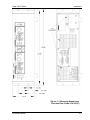
1
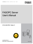
CW-P SERIES PROGRAMMABLE AC POWER SOURCE Operation Manual This manual covers models: CW 801P CW 1251P CW 2501P CW 801P–H CW 1251P–H CW 2501P–H CW 801P–V CW 1251P–V CW 2501P–V Contact Information Telephone: 800 733 5427 (toll free in North America) 858 450 0085 (direct) Fax: 858 458 0267 Email: Domestic Sales: [email protected] International Sales: [email protected] Customer Service: [email protected] Web: www.programmablepower.com March 2011 Document No. M161691-01 Rev J About AMETEK AMETEK Programmable Power, Inc., a Division of AMETEK, Inc., is a global leader in the design and manufacture of precision, programmable power supplies for R&D, test and measurement, process control, power bus simulation and power conditioning applications across diverse industrial segments. From bench top supplies to rack-mounted industrial power subsystems, AMETEK Programmable Power is the proud manufacturer of Elgar, Sorensen, California Instruments and Power Ten brand power supplies. AMETEK, Inc. is a leading global manufacturer of electronic instruments and electromechanical devices with annualized sales of $2.5 billion. The Company has over 11,000 colleagues working at more than 80 manufacturing facilities and more than 80 sales and service centers in the United States and around the world. Trademarks AMETEK is a registered trademark of AMETEK, Inc. Other trademarks, registered trademarks, and product names are the property of their respective owners and are used herein for identification purposes only. Notice of Copyright CW-P Series Programmable AC Power Source, Operation Manual © 2010 AMETEK Programmable Power, Inc. All rights reserved. Exclusion for Documentation UNLESS SPECIFICALLY AGREED TO IN WRITING, AMETEK PROGRAMMABLE POWER, INC. (“AMETEK”): (a) MAKES NO WARRANTY AS TO THE ACCURACY, SUFFICIENCY OR SUITABILITY OF ANY TECHNICAL OR OTHER INFORMATION PROVIDED IN ITS MANUALS OR OTHER DOCUMENTATION. (b) ASSUMES NO RESPONSIBILITY OR LIABILITY FOR LOSSES, DAMAGES, COSTS OR EXPENSES, WHETHER SPECIAL, DIRECT, INDIRECT, CONSEQUENTIAL OR INCIDENTAL, WHICH MIGHT ARISE OUT OF THE USE OF SUCH INFORMATION. THE USE OF ANY SUCH INFORMATION WILL BE ENTIRELY AT THE USER’S RISK, AND (c) REMINDS YOU THAT IF THIS MANUAL IS IN ANY LANGUAGE OTHER THAN ENGLISH, ALTHOUGH STEPS HAVE BEEN TAKEN TO MAINTAIN THE ACCURACY OF THE TRANSLATION, THE ACCURACY CANNOT BE GUARANTEED. APPROVED AMETEK CONTENT IS CONTAINED WITH THE ENGLISH LANGUAGE VERSION, WHICH IS POSTED AT WWW.PROGRAMMABLEPOWER.COM. Date and Revision March 2011 Revision J Part Number M161691-01 Contact Information Telephone: Fax: Email: Web: 800 733 5427 (toll free in North America) 858 450 0085 (direct) 858 458 0267 [email protected] [email protected] www.programmablepower.com i This page intentionally left blank. ii Important Safety Instructions Before applying power to the system, verify that your product is configured properly for your particular application. Hazardous voltages may be present when covers are removed. Qualified personnel must use extreme caution when servicing this equipment. Circuit boards, test points, and output voltages also may be floating above WARNING (below) chassis ground. The equipment used contains ESD sensitive ports. When installing equipment, follow ESD Safety Procedures. Electrostatic discharges might cause damage to the equipment. WARNING Only qualified personnel who deal with attendant hazards in power supplies, are allowed to perform installation and servicing. Ensure that the AC power line ground is connected properly to the Power Rack input connector or chassis. Similarly, other power ground lines including those to application and maintenance equipment must be grounded properly for both personnel and equipment safety. Always ensure that facility AC input power is de-energized prior to connecting or disconnecting any cable. In normal operation, the operator does not have access to hazardous voltages within the chassis. However, depending on the user’s application configuration, HIGH VOLTAGES HAZARDOUS TO HUMAN SAFETY may be normally generated on the output terminals. The customer/user must ensure that the output power lines are labeled properly as to the safety hazards and that any inadvertent contact with hazardous voltages is eliminated. Guard against risks of electrical shock during open cover checks by not touching any portion of the electrical circuits. Even when power is off, capacitors may retain an electrical charge. Use safety glasses during open cover checks to avoid personal injury by any sudden component failure. Neither AMETEK Programmable Power Inc., San Diego, California, USA, nor any of the subsidiary sales organizations can accept any responsibility for personnel, material or inconsequential injury, loss or damage that results from improper use of the equipment and accessories. SAFETY SYMBOLS iii Product Family: CW801P, CW1251P, CW2501P, CW801P-H, CW1251P-H, CW2501P-H, CW801P-V, CW1251P-V, CW2501P-V Warranty Period: One Year WARRANTY TERMS AMETEK Programmable Power, Inc. (“AMETEK”), provides this written warranty covering the Product stated above, and if the Buyer discovers and notifies AMETEK in writing of any defect in material or workmanship within the applicable warranty period stated above, then AMETEK may, at its option: repair or replace the Product; or issue a credit note for the defective Product; or provide the Buyer with replacement parts for the Product. The Buyer will, at its expense, return the defective Product or parts thereof to AMETEK in accordance with the return procedure specified below. AMETEK will, at its expense, deliver the repaired or replaced Product or parts to the Buyer. Any warranty of AMETEK will not apply if the Buyer is in default under the Purchase Order Agreement or where the Product or any part thereof: is damaged by misuse, accident, negligence or failure to maintain the same as specified or required by AMETEK; is damaged by modifications, alterations or attachments thereto which are not authorized by AMETEK; is installed or operated contrary to the instructions of AMETEK; is opened, modified or disassembled in any way without AMETEK’s consent; or is used in combination with items, articles or materials not authorized by AMETEK. The Buyer may not assert any claim that the Products are not in conformity with any warranty until the Buyer has made all payments to AMETEK provided for in the Purchase Order Agreement. PRODUCT RETURN PROCEDURE 1. Request a Return Material Authorization (RMA) number from the repair facility (must be done in the country in which it was purchased): In the USA, contact the AMETEK Repair Department prior to the return of the product to AMETEK for repair: Telephone: 800-733-5427, ext. 2295 or ext. 2463 (toll free North America) 858-450-0085, ext. 2295 or ext. 2463 (direct) Outside the United States, contact the nearest Authorized Service Center (ASC). A full listing can be found either through your local distributor or our website, www.programmablepower.com, by clicking Support and going to the Service Centers tab. 2. When requesting an RMA, have the following information ready: Model number Serial number Description of the problem NOTE: Unauthorized returns will not be accepted and will be returned at the shipper’s expense. NOTE: A returned product found upon inspection by AMETEK, to be in specification is subject to an evaluation fee and applicable freight charges. iv CONTENTS SECTION 1 INTRODUCTION ............................................................. 0-1 SECTION 2 SPECIFICATIONS .......................................................... 1-1 2.1 Output................................................................................................... 1-1 2.2 Measurement ....................................................................................... 1-3 2.3 Input ..................................................................................................... 1-5 2.4 Protection ............................................................................................. 1-6 2.5 Rear Panel Connections....................................................................... 1-6 2.6 General ................................................................................................. 1-6 2.7 Options and Accessories ...................................................................... 1-7 SECTION 3 INSTALLATION .............................................................. 2-1 3.1 Unpacking ............................................................................................ 2-1 3.2 Wire Gauge Selection .......................................................................... 2-2 3.3 Mounting Instructions ........................................................................... 2-5 3.4 Cooling ................................................................................................. 2-5 3.5 Power In Connections ........................................................................ 2-10 3.5.1 Single–Phase Supply Connections ......................................... 2-10 3.5.2 Split-Phase Supply Connections 120–0–120V ....................... 2-11 3.5.3 Three–Phase Supply Connections ......................................... 2-11 3.6 Power Out Connections...................................................................... 2-12 3.7 Sense Connections ............................................................................ 2-13 Operation Manual v Contents 3.8 3.9 Elgar CW-P Series Remote Control Signal ........................................................................ 2-15 3.8.1 Analog Amplitude Control ........................................................ 2-15 3.8.2 Lock to External Frequency Source ........................................ 2-15 3.8.3 Sync Output Pulse ................................................................... 2-16 Master/Slave Configurations ............................................................... 2-16 3.9.1 Setup for Single–Phase, Two Units ......................................... 2-17 3.9.2 Setup for Three–Phase, Two Units per Phase ........................ 2-20 SECTION 4 OPERATION .................................................................. 3-1 4.1 CW Front Panel Controls and Indicators .............................................. 3-1 4.2 Front Panel Overview ............................................................................ 3-4 4.3 Power Up .............................................................................................. 3-5 4.4 Programmed Frequency Steps ............................................................. 4-6 SECTION 5 5.1 5.2 5.3 PROGRAMMING ............................................................ 4-1 Programming the CW Via the Front Panel ............................................ 4-1 5.1.1 VOLTAGE/POWER Section ...................................................... 4-2 5.1.2 CURRENT/FREQUENCY Section............................................. 4-2 Measurement Operations ..................................................................... 4-2 5.2.1 Supply Measurements on the Left Display ................................ 4-2 5.2.2 Supply Measurements on the Right Display .............................. 4-3 Menu Operations .................................................................................. 4-4 5.3.1 Self Test .................................................................................... 4-5 5.3.2 Set GPIB Port ............................................................................ 4-5 5.3.3 Specify Current Limit Type ........................................................ 4-6 5.3.4 Specify Shutdown Delay............................................................ 4-6 5.3.5 Specify Program Keys Locked Mode ........................................ 4-6 5.3.6 Store Present Machine Settings ................................................ 4-6 5.3.7 Recall Machine Settings ............................................................ 4-7 5.3.8 Specify Relay State After Power Up Initialization ...................... 4-7 5.3.9 Clock Direction .......................................................................... 4-7 5.3.10 Analog Input State.................................................................... 4-7 vi Operation Manual Elgar CW-P Series Contents 5.3.11 RMS Voltage Loop .................................................................. 4-8 5.3.12 Phase A Offset ........................................................................ 4-8 5.3.13 Phase B Offset ........................................................................ 4-8 5.3.14 Phase C Offset ........................................................................ 4-8 5.3.15 Slave Channel ......................................................................... 4-8 5.3.16 Slave Address ......................................................................... 4-8 5.3.17 Slave Configuration ................................................................. 4-8 SECTION 6 MAINTENANCE .............................................................. 5-1 6.1 Periodic Service.................................................................................... 5-1 6.2 Fuse Replacement ............................................................................... 5-1 LIST OF FIGURES Figure 1–1 ContinuousWave Front Panel (Model CW 801P) ...................... 1-1 Figure 3–1 Slide Mounting ........................................................................... 3-5 Figure 3–2 Mounting Dimensions, Front and Rear Views (CW 801P and CW 1251P) ....................................................... 3-6 Figure 3–3 Mounting Dimensions, Front and Rear Views (CW 2501P) ....... 3-7 Figure 3–4 Mounting Dimensions, Top and Side Views (CW 801P and CW 1251P) ....................................................... 3-8 Figure 3–5 Mounting Dimensions, Top and Side Views (CW 2501P) ........ 3-9 Figure 3–6 Input Power Connections ........................................................ 3-10 Figure 3–7 Output Power Connections ...................................................... 3-12 Figure 3–8 Output Voltage Sensing Configuration .................................... 3-13 Figure 3–9 Sense Connections ................................................................. 3-14 Figure 3–10 M/S IN Connector .................................................................... 3-15 Figure 3–11 Wiring Diagram for One Phase, Master/Slave Configuration .. 3-17 Figure 3–12 Wiring Diagram for Three Phase, Master/Slave Configuration 3-20 Figure 4–1 Operation Manual Front Panel Controls (CW 801P) ............................................... 4-1 vii Contents Elgar CW-P Series LIST OF TABLES Table 3–1 Recommended Wire Gauge Selection Guide ............................... 2-2 Table 3–2 Recommended Cables ............................................................... 2-11 Table 6–1 Replacement Fuses ...................................................................... 5-1 viii Operation Manual SECTION 0 INTRODUCTION Elgar's ContinuousWave™ (CW) Series power sources deliver 800 VA or 1250 VA in a 2U high (3.5 inches), and 2500 VA in a 5.25–inch benchtop or rackmount chassis. Higher power and multiphase can be achieved by paralleling and multiphase interconnection. This requires optional slave cables. The switchmode Power Factor Corrected (PFC) input stage allows a wide range of input voltage and maximizes the power available from a wall outlet. The CW series units are available in manual and programmable versions. This operation manual covers the programmable versions only. Voltage, current, and frequency settings are quickly adjusted from the front panel encoders. In addition, the sources can be programmed remotely from the rear panel GPIB, RS-232, or analog port. The output is protected against overvoltage, overcurrent, and overtemperature conditions. A two-speed fan results in quieter operation at lower power levels. Figure 0–1 ContinuousWave Front Panel (Model CW 801P) Key features of the CW Series AC power sources include: High performance/value design 800, 1250, and 2500 VA units available Low profile 3.5" rack height required for up to 1250 VA; 5.25" rack height required for 2500 VA Bench top or rack mount (optional slides available) Operation Manual 0-1 Introduction Elgar CW-P Series 1 phase 45 to 500 Hz AC output; 45-1000 Hz with H–Option. Units may be connected in multiphase configuration and/or paralleled for higher powers. (Consult factory for more than two units paralleled.) Multiphase/paralleling cables are optional. Transformer coupled output with disconnect relays 0 to 135V and 0 to 270V ranges; 0 to 155V and 0 to 310V ranges with V–Option CW 801P and CW 1251P versions have universal output socket on front panel. All units have output power available at rear of unit. Remote sense leads for accurate output voltage Input PFC provides maximum utilization of available outlet current and wide range of input voltage and frequency CE mark UL/CUL (consult factory for availability) GPIB and RS-232 control Two large, 7-segment LED, 4-digit displays on front panel Set volts, overvoltage, frequency, current, and overcurrent by two front panel encoders Measure voltage, wattage, VA, power factor, current, peak current, and crest factor Display overvoltage, frequency, and overcurrent setting Over current shutdown or constant current mode menu-selectable Enable/disable output voltage rms loop menu-selectable Sync in, clock out, and analog programming of output voltage available through rear panel connector. These items are menu-selectable. Front panel lockout; measurement active Stored settings including: Power up to previous front panel setting or 0V 2-speed fan for low noise Side air intake, exhaust to rear All connectors on rear (output power also available at front for CW 801P and CW 1251P) Chassis depth 20" (front panel and rear connectors add additional depth) Will fit in 24" RETMA rack system 1-year calibration interval, covers on soft calibration 0-2 Operation Manual SECTION 1 SPECIFICATIONS 1.1 Output POWER CW 801P 800 VA CW 1251P 1250 VA CW 2501P 2500 VA Power Factor of Load 0 lag to 0 lead Phase All models single phase output VOLTAGE Ranges 0 to 135 VRMS or 0 to 270 VRMS, user selectable V–Option: 0 to 155 VRMS or 0 to 310 VRMS, user selectable Accuracy ±0.1% of full scale <100 Hz, ±0.2% of full scale ≥100 Hz at >5 VRMS output H–Option: ± 0.3% of full scale >500 Hz Resolution 0.1 VRMS AC Noise Level CW 801/1251P: <50 mVRMS typical in low-voltage range <85 mVRMS typical in high-voltage range CW 2501P: <100 mVRMS typical in low-voltage range <170 mVRMS typical in high-voltage range H–Option/V–Option: CW 801/1251P: <75 mVRMS typical in low-voltage range <125 mVRMS typical in high-voltage range CW 2501P: Operation Manual <125 mVRMS typical in low-voltage range <225 mVRMS typical in high-voltage range 1-1 Specifications Total Harmonic Distortion Elgar CW-P Series 0.25% typical ≤60 Hz; add 0.05%/10 Hz from >60 Hz to 100 Hz; add 0.5%/100 Hz at >100 Hz H–Option: 0.5% typical ≤60 Hz; add 0.05%/10 Hz from >60 Hz to 100 Hz; add 0.5%/100 Hz at >100 Hz up to 3.7%; increasing to 6% at 10% of full scale voltage, 100% full scale current, and full scale frequency Amplitude Stability ±0.05% of full scale over 8 hours at constant line, load and temperature after 15 minute warm-up typical Load Regulation ±0.1% full scale voltage for full resistive load to no load (<10 mVRMS typical, measured at point of sense) Line Regulation ±0.1% of full scale voltage for a ±10% line change from nominal line voltage (<5 mVRMS typical, measured at point of sense) Remote Voltage Sense 5 VRMS total lead voltage drop CURRENT CW 801P(–H) CW 1251P(–H) CW 2501P(–H) 6.0 ARMS (135 VAC range), 3.0 ARMS (270 VAC range) 9.4 ARMS (135 VAC range), 4.7 ARMS (270 VAC range) 18.6 ARMS (135 VAC range), 9.3 ARMS (270 VAC range) CW 801P–V CW 1251P–V CW 2501P–V 5.2 ARMS (155 VAC range), 2.6 ARMS (310 VAC range) 8.2 ARMS (155 VAC range), 4.1 ARMS (310 VAC range) 16.2 ARMS (155 VAC range), 8.1 ARMS (310 VAC range) Accuracy ±0.5% of full scale typical; for linear loads and >0.12 ARMS for CW 801P, >0.19 ARMS for CW 1251P, >0.37 ARMS for CW 2501P H–Option/V–Option: ±0.75% of full scale and ≤500 Hz; ±1.0% of full scale and >500Hz Resolution 0.01 ARMS FREQUENCY Range 45 to 500 Hz (45 to 1000 Hz for H-Option) Accuracy ±0.02% maximum Resolution 0.1 Hz, 0.01 Hz for remote programming 1-2 Operation Manual Elgar CW-P Series Specifications PHASE Range -359 to +359 degrees Positive phase indicates time lag from reference Accuracy Within 100 microseconds of equivalent angle Resolution 1 degree 1.2 Measurement VOLTAGE Range 0 to 270 VRMS; V–Option: 0 to 310 VRMS Accuracy ±0.1% of range <100 Hz; ±0.2% of range ≥100Hz; at >5 VRMS output; measured at point of remote sense H-Option: ±0.3% of range >500 Hz Resolution 0.1 VRMS CURRENT* Range CW 801P 0 to 6.0 ARMS CW 1251P 0 to 9.4 ARMS CW 2501P 0 to 18.6 ARMS Accuracy ±0.5% of range typical; for linear loads and >0.12 ARMS for CW 801P, >0.19 ARMS for CW 1251P, >0.37 ARMS for CW 2501P H–Option/V–Option: ±0.75% of range and ≤500 Hz; ±1.0% of range and >500 Hz Resolution 0.01 ARMS PEAK INSTANTANEOUS CURRENT* Range CW 801P 0 to 25A CW 1251P 0 to 35A CW 2501P 0 to 70A Accuracy ±2% of range typical; at >2% current range Resolution 0.1A Operation Manual 1-3 Specifications Elgar CW-P Series PEAK INRUSH CURRENT* (Available in Remote Mode only) Range CW 801P 0 to 25A CW 1251P 0 to 35A CW 2501P 0 to 70A Accuracy ±2% of range, typical; at >2% of RMS current range Resolution 0.1A FREQUENCY Range 45 to 500 Hz H-Option: 45 to 1000 Hz Accuracy ±0.02% of value Resolution of Display 0.1 Hz POWER* Range CW 801P 0 to 800W CW 1251P 0 to 1250W CW 2501P 0 to 2500W Accuracy ±2% of range for linear loads, typical Resolution 1W APPARENT POWER* Range CW 801P 0 to 800 VA CW 1251P 0 to 1250 VA CW 2501P 0 to 2500 VA Accuracy ±2% of range for linear loads, typical Resolution 1 VA 1-4 Operation Manual Elgar CW-P Series Specifications POWER FACTOR* Range 0 to 1 Accuracy ±4% of range for linear loads, typical; at >10% of power range Resolution 0.01 CREST FACTOR* Range 0 to 3.5 Accuracy ±5% of range, typical; at 10% of RMS current range Resolution 0.01 1.3 Input VOLTAGE AND FREQUENCY CW 801P 90 to 264 VRMS, 47 to 63 Hz, single-phase CW 1251P 103 to 264 VRMS, 47 to 63 Hz, single-phase CW 2501P 180 to 264 VRMS, 47 to 63 Hz, single-phase CURRENT CW 801P(–H)(–V) 13.5 ARMS, maximum at 90 VRMS CW 1251P(–H)(–V) 17.7 ARMS , maximum at 103 VRMS CW 2501P(–H)(–V) 19.7 ARMS , maximum at 180 VRMS POWER FACTOR >0.99 typical at full load nominal line EFFICIENCY >73% typical at full load H–Option/V–Option at 1,000 Hz: CW 801P, >68% typical; CW 1251P, >70% typical; CW 2501P, >72% typical *Note: In a parallel system, the current/power displayed on the master unit is the sum of all units in the system. Operation Manual 1-5 Specifications 1.4 Elgar CW-P Series Protection Overcurrent: Shutdown mode Accuracy: +/- 1% of full scale, for linear loads with current >0.2 ARMS for CW 801P / CW 1251P, >0.4ARMS for CW 2501P Over Voltage: Accuracy: +/-2% of full scale Range: 35-300 VAC; V–Option: 35-344 VAC Over Temperature: Internal monitor Isolation Range: 1.5 500 VRMS between either output terminal and chassis. Rear Panel Connections GPIB RS-232 M/S OUT M/S IN ANALOG SLAVE Power In and Power Out Terminal Strips (see Sections 2.5 and 2.6) 1.6 General DIMENSIONS CW 801P: 3.5" (89 mm) H x 19" (483 mm) W x 20.6" (524 mm) D CW 1251P: 3.5" (89 mm) H x 19" (483 mm) W x 20.6" (524 mm) D CW 2501P: 5.25" (133 mm) H x 19" (483 mm) W x 20.6" (524 mm) D WEIGHT CW 801P: 48 lbs. (22 kg) CW 1251P: 53 lbs. (24 kg) CW 2501P: 86 lbs. (40 kg) 1-6 Operation Manual Elgar CW-P Series Specifications SHIPPING WEIGHT CW 801P: 55.25 lbs. (25 kg) CW 1251P: 60.25 lbs. (27 kg) CW 2501P: 93.25 lbs. (43 kg) REGULATORY COMPLIANCE CE mark UL and CUL (consult factory for availability) ENVIRONMENTAL Cooling: Dual fan speed with side air intake, exhaust to rear Operating Temperature: 0 to 40°C Storage Temperature: -40 to +70°C Humidity: 0 to 85% at 25°C derate to 50% above 40°C (non-condensing) Altitude: Operating full power available up to 6,000 feet, non-operating to 40,000 feet Installation Category III, Pollution Degree 2 FOR INDOOR USE ONLY 1.7 Options and Accessories Rack Slide Kit (Elgar part number K161570-01) Multiphase/Parallel Cable (Elgar part number 890-499-00) Master/Slave Cable (Elgar part number 890-497-40) S: Sync In/Out (Clock/Lock) H: Expanded Frequency Range 45 to 1000 Hz V: Expanded Voltage Range 0-155/0-310 VRMS Note: Product specifications are subject to change without notice. Operation Manual 1-7 Specifications Elgar CW-P Series This page intentionally left blank. 1-8 Operation Manual SECTION 2 INSTALLATION The Elgar CW series power supply has been fully calibrated and tested prior to shipment. The instrument is ready for immediate use upon receipt. CAUTION! The CW unit weighs from 48 to 86 lbs. (22 to 40 kg), depending on the model. A two–person lift is recommended. WARNING! Hazardous voltages are present when operating this equipment. Please read the Safety Notice at the beginning of this manual prior to installation, operation, or maintenance. 2.1 Unpacking Perform a visual inspection of the shipping container prior to accepting the package from the carrier. If extensive damage to the shipping container is evident, a description of the damage should be noted on the carrier's receipt and signed by the driver of the carrier agent. Perform a visual inspection of the instrument when it is removed from the shipping container. Check for shipping damage such as dents, scratches, distortion, and damaged connectors. If damage is not apparent until the instrument is unpacked, a claim for concealed damage should be placed with the carrier. In addition, the shipping container(s) and filler material should be saved for inspection. Forward a report of damage to the Elgar Service Department. Elgar will provide instructions for repair or replacement of the instrument. If the instrument needs to be returned to Elgar, suitable shipping containers and packing materials must be used. If proper packing material is not available, contact Elgar to provide containers and shipping instructions. Before shipping a product to Elgar, you must obtain a Return Material Authorization (RMA) number from Elgar‟s Repair Department. See the warranty page at the front of this manual for details. Operation Manual 2-1 Installation 2.2 Elgar CW-P Series Wire Gauge Selection The following guidelines assist in determining the optimum cable specification for your power applications. These guidelines are equally applicable to both DC and low frequency AC (up to 450 Hz) power cabling. The same engineering rules apply whether going into or out of an electrical device. Thus, this guide applies equally to the input cable and output cable for this Elgar instrument and application loads. Power cables must be able to safely carry maximum load current without overheating or causing insulation destruction. It is important to everyday performance to minimize IR (voltage drop) loss within the cable. These losses have a direct effect on the quality of power delivered to and from instruments and corresponding loads. When specifying wire gauge, the operating temperature needs to be considered. Wire gauge current capability and insulation performance drops with the increased temperature developed within a cable bundle and with increased environmental temperature. Thus, short cables with generously derated gauge and insulation properties are recommended for power source applications. Avoid using published commercial utility wiring codes, which are designed for the internal wiring of homes and buildings. Although these codes accommodate the safety factors of wiring loss, heat, breakdown insulation, aging, etc., they consider that up to 5% voltage drop is acceptable. Such a loss directly detracts from the quality performance specifications of this Elgar instrument. Frequently, these codes do not consider bundles of wire within a cable arrangement. In high performance applications, as in motor start-up and associated inrush/ transient currents, additional consideration is required. The cable wire gauge must consider peak voltages and currents that may be up to ten times the average values. An underrated wire gauge adds losses that alter the inrush characteristics of the application and thus the expected performance. Table 2–1 identifies popular ratings for DC and AC power source cable wire gauges. Column 1 Size (AWG) Column 2 Amperes (Max) Column 3 Ohms/100 ft (1 way) Column 4 IR Drop/100 ft (Col 2 x Col 3) 14 12 10 8 6 4 2 1/0 3/0 15 20 30 40 55 70 95 125 165 0.257 0.162 0.102 0.064 0.043 0.025 0.015 0.010 0.006 3.85 3.24 3.06 2.56 2.36 1.75 1.42 1.25 1.04 Table 2–1 Recommended Wire Gauge Selection Guide 2-2 Operation Manual Elgar CW-P Series Installation The following notes apply to Table 2–1 and to the power cable definition: 1. The above figures are based upon insulated copper conductors at 25C (77F), two current carrying conductors in the cable plus a safety (chassis) ground. Columns 3 and 4 refer to “one way” ohms and IR drop of current carrying conductors (e.g., a 50-foot cable contains 100 feet of current carrying conductor). 2. Determine which wire gauge for the application by knowing the expected peak load current (Ipeak), the maximum tolerated voltage loss (Vloss) within the cable, and the one way cable length. The formula below determines which ohms/100 feet entry is required from Column 3. Read the corresponding wire gauge from Column 1. (Column 3 value) = Vloss/[Ipeak x 0.02 x (cable length)] Where: Column 3 value = Entry of the table above. Cable length = One way cable length in feet. Vloss = Maximum loss, in volts, permitted within cable. Special case: Should the Vloss requirement be very loose, Ipeak may exceed the maximum amperes (Column 2). In this case, the correct wire gauge is selected directly from the first two columns of the table. Example: A 20 ampere (Ipeak) circuit which may have a maximum 0.5 volt drop (Vloss) along its 15-foot cable (one way cable length) requires (by formula) a Column 3 resistance value of 0.083. This corresponds to wire gauge size 8 AWG. If the cable length was 10 feet, the Column 3 value would be 0.125 and the corresponding wire gauge would be 10 AWG. 3. Aluminum wire is not recommended due to soft metal migration at the terminals which may cause long term (on the order of years) poor connections and oxidation. If used, increase the wire gauge by two sizes (e.g., specify 10 gauge aluminum instead of 14 gauge aluminum). Operation Manual 2-3 Installation 4. 5. 6. Elgar CW-P Series Derate the above wire gauge (use a heavier gauge) for higher environmental temperatures since conductor resistance increases with temperature. Temperature Current Capability 40°C 104°F 80% Derate the above wire gauge (use a heavier gauge) for an increased number of current carrying conductors. This offsets the thermal rise of bundled conductors. No. of Conductors Current Capability 3 to 6 Above 6 80% 70% The preferred insulation material is application dependent. Elgar's recommendation is any flame retardant, heat resistant, moisture resistant thermoplastic insulation rated to a nominal 75°C (167°F). Voltage breakdown must exceed the combined effects of: The rated output voltage; Transient voltages induced onto the conductors from any source; The differential voltage to other nearby conductors; and, Safety margins to accommodate degradations due to age, mechanical abrasion and insulation migration caused by bending and temperature. 7. As frequency increases, the magnetic field of the current carrying conductors becomes more significant in terms of adverse coupling to adjacent electrical circuits. Use twisted pairs to help cancel these effects. Shielded twisted pairs are even better. Avoid close coupling with nearby cables by using separate cable runs for high power and low power cables. 8. The above general values and recommendations should be reviewed, modified, and amended as necessary for each application. Cables should be marked with appropriate safety WARNING decals as hazardous voltages may be present. 2-4 Operation Manual Elgar CW-P Series 2.3 Installation Mounting Instructions Refer to Figure 2–1 through Figure 2–4 for mounting dimensions and other installation information for the CW Series power supplies. The units are equipped with mounting feet for bench top use. They are mounted to the chassis with pem-nuts and may be removed easily for rack mount application. The units are 3.5" and 5.25" (89 mm and 133 mm) high, and are designed to be installed in a standard 19" (483 mm) RETMA rack. Pem-nuts have been built into the chassis for mounting optional slides. The CW mounting kit, Elgar part number K161570-01, contains the appropriate slides and mounting brackets. If you elect not to use slides, mount the unit with standard support angles to sustain the weight of the unit in the rack. Note that the front panel mounting ears are not intended to support its weight in rack mounting. For installations that include slides, use a #10 lock washer, as supplied in the CW-P mounting kit, with each of the two mounting screws indicated in Figure 2–1. These washers are required on the right side only to limit the depth of screw penetration into the chassis, which must be less than 0.25". Figure 2–1 Slide Mounting 2.4 Cooling The CW unit employs internal fans to circulate cooling air. The air is drawn into the chassis along its sides, and is exhausted through the rear panel. For maximum product life and reliability, do not allow the airflow to be impeded. CAUTION! Avoid blocking the instrument air intakes or exhaust. Operation Manual 2-5 Installation Elgar CW-P Series Figure 2–2 Mounting Dimensions, Front and Rear Views (CW 801P, CW 1251P) 2-6 Operation Manual Elgar CW-P Series Installation Figure 2–3 Mounting Dimensions, Front and Rear Views (CW 2501P) Operation Manual 2-7 Installation Elgar CW-P Series Figure 2–4 Mounting Dimensions, Top and Side Views (CW 801P and CW 1251P) 2-8 Operation Manual Elgar CW-P Series Installation Figure 2–5 Mounting Dimensions, Top and Side Views (CW 2501P) Operation Manual 2-9 Installation 2.5 Elgar CW-P Series Power In Connections Connect input power to the INPUT terminal block on the rear panel as specified below. Refer to Figure 2–6. Figure 2–6 Input Power Connections WARNING! For input voltages >120V, do not reverse LINE and NEUT. Reversed connections will result in pulsing noises from the supply. 2.5.1 Single–Phase Supply Connections 1. Remove the protective cover from the terminal block. 2. Route the cables through the strain relief device. Refer to Table 2–2 for cable recommendations. 3. Connect SAFETY GROUND to the GROUND stud located next to the INPUT terminal block. For additional safety, include a loop between the GROUND stud and the strain relief device, as shown in Figure 2–6. 4. Connect shields, if any, to the GND connector of the INPUT terminal block. 5. Connect NEUTRAL, if available, to the NEUT connector. 6. Connect LINE to the LINE connector. 7. Reinstall the protective cover on the terminal block. Tighten the strain relief device. 2-10 Operation Manual Elgar CW-P Series 2.5.2 Installation Split-Phase Supply Connections 120–0–120V 1. Remove the protective cover from the terminal block. 2. Route the cables through the strain relief device. Refer to Table 2–2 for cable recommendations. 3. Connect NEUT to 120V. 4. Connect LINE to the other 120V. Wiring across the full voltage will allow lower line currents to be used. 5. Reinstall the protective cover on the terminal block. Tighten the strain relief device. 2.5.3 Three–Phase Supply Connections 1. Remove the protective cover from the terminal block. 2. Route the cables through the strain relief device. Refer to Table 2–2 for cable recommendations. 3. Connect one phase to LINE and Neutral to NEUT. If Neutral is not available, connect LINE and NEUT across any of the phases. 4. Reinstall the protective cover on the terminal block. Tighten the strain relief device. CW Model North American 18A/300V, 3x14 AWG O.D.=9.6 mm CW 801P CW 1251P and CW 2501P 25A/300V, 3x12 AWG O.D.=11.3 mm International 16A/300V, 3x1.5 mm2 O.D.=8.0–9.8 mm 25A/300V, 3x2.5 mm2 O.D.=9.6–12.0 mm VDE approved Table 2–2 Recommended Cables WARNING! To protect the operator, the wire connected to the GND terminal must be connected to earth ground. This unit should not be operated without an adequate ground connection. CAUTION! A device to disconnect the CW system from the energy supply source is required. This switch or circuit breaker must be close to the CW system, within easy reach of the operator, and clearly labeled as the disconnection device for the CW system. CAUTION! Use wire rated for currents drawn as specified on equipment label. Operation Manual 2-11 Installation 2.6 Elgar CW-P Series Power Out Connections 1. Remove the protective cover from the terminal block. 2. A factory jumper has been added to connect NEUTRAL to GROUND. If the front connector requires LINE and NEUTRAL to be reversed, move this jumper to connect LINE to GROUND. See Figure 2–7 below. Most loads require NEUTRAL to be grounded. The factory jumper may be removed if the load has a GROUND or if LINE or NEUTRAL voltages are held to less than 500 VRMS with respect to chassis. 3. Reinstall the protective cover on the terminal block. WARNING! Verify that the load is set up to be LINE GROUNDED or NEUTRAL GROUNDED. (Equipment with polarized plugs requires NEUTRAL to be grounded.) Figure 2–7 Output Power Connections 2-12 Operation Manual Elgar CW-P Series 2.7 Installation Sense Connections The CW Series unit can be used with or without remote sense leads connected to the load. Where the sense leads (line and neutral sense) are connected determines the point at which the CW output voltage will be precisely regulated. As shipped, the units are configured for local sense operation. This is achieved by connecting shorting jumpers between the sense and AC output terminals of the rear panel output terminal block, as shown in Figure 2–8. When using remote sensing, the shorting jumpers must be removed, and the remote sense leads connected from the CW sense terminals to the load. The point of voltage regulation will now be at the load, and any voltage drop across the interconnecting output cable will be compensated. In the event that the external remote sense circuit opens, the CW maintains control of the output voltage by utilizing a redundant sense circuit. This redundant circuit is comprised of 10kΩ resistors internally connected from the AC output terminals to the voltage control circuitry. However, since the unit is calibrated with the sense leads connected, this mode of operation will incur reduced accuracy in the AC output voltage because of the presence of the 10kΩ resistors. Figure 2–8 Output Voltage Sensing Configuration Operation Manual 2-13 Installation Elgar CW-P Series To utilize remote sensing at the user's load, follow these steps: 1. Remove the protective cover from the terminal block. 2. Route the cables through the strain relief device located above the terminal block. Twisted shielded leads for power and sense leads are recommended for the lowest noise operation. If used, shields should be connected to a CW output terminal block GND ground connector, as shown in Figure 2–9. 3. Disconnect local–sense shorting jumpers. See Figure 2–9 4. Connect the sense leads as shown in Figure 2–9. 5. Reinstall the protective cover on the terminal block. Figure 2–9 Sense Connections 2-14 Operation Manual Elgar CW-P Series 2.8 Installation Remote Control Signal Remote control allows you to set output voltage, lock to an external frequency source, or send out a TTL compatible sync signal. The 9-pin Subminiature-D master/slave connector labeled M/S IN on the rear panel allows you to make the necessary connections for remote control. See Figure 2–10. Pins 1, 2, 3, 6, 7, and 8 of the M/S IN connector provide control signals for multiphase/paralleled systems; do not make any user connections to these pins. In a multiphase/paralleled system, the master unit uses the M/S IN connector for analog amplitude control or synchronizing to external frequency sources. Pin Number Function 4 User Ground (at GPIB Ground potential) 5 Analog Amplitude Control (0 to 5 VDC for zero to set maximum voltage) 9 Clock Lock Input/Output 1, 2, 3, 6, 7, 8 Do not make connection Figure 2–10 M/S IN Connector 2.8.1 Analog Amplitude Control Set unit to Analog In (analog input state = ON. See Section 4.3.10). Set HIGH or LOW range, and maximum output voltage (corresponding to 5 VDC analog amplitude control) by front panel, GPIB, or RS232 command. 0 to 5 VDC will set the output from 0 to the maximum voltage programmed (on the range selected), as set by front panel controls, GPIB, or RS232 command. If needed, set „Program keys locked mode.‟ See section 4.3.5. 2.8.2 Lock to External Frequency Source Set direction of Clock to „IN‟ (see Section 4.3.9). Signal can be 2 to 12V amplitude, and at least 10 microseconds wide. Triggering shall occur on the leading edge of the pulse. For zero programmed phase delay the output sinewave shall go from zero to positive. Delay angle can be programmed 0 to 359 degrees with a resolution of 1 degree. Input impedance is typically 10k ohm. Operation Manual 2-15 Installation 2.8.3 Elgar CW-P Series Sync Output Pulse Set direction of Clock to „OUT‟ (see Section 4.3.9). Sync can be programmed relative to zero to positive crossing of output sinewave. Waveform amplitude typically 5V. Pulse width typically 10 microseconds. Signal shall start with a zero volt to positive voltage edge, ±100 S. Programming range is 0 to 359 degrees of lag. Resolution 1 degree. Output impedance is typically less than 1k ohm. 2.9 Master/Slave Configurations The CW-P series programmable power supply can be paralleled to achieve higher power. One, two, or three phase(s) can be paralleled to a depth of two units per phase. A given phase will have one “Master” and one or more “Slaves.” The master and slave require special cables (two) between them. The outputs must be connected together with equal gauge and length power leads, the sense leads must be connected on the master, and each unit requires special programming. Programming of the units is performed from the front panel through the menu systems, or through the GPIB/ RS-232 command interface. Once a unit is configured to be a slave, its command interface is not to be used when load wiring is connected. When a multi-phase master/slave configuration is configured, the only GPIB/RS-232 connected unit is to be the A phase master. Attempting to control any other units in the array is specified as an illegal operation, and the results are undefined and potentially destructive. The command interfaces of a slave are allowed to remain operational for the purpose of returning the unit to a standalone or different slave configuration. Note: Remove load wiring before reconfiguring a slave unit via the menu or command interfaces. The CW-P series power supplies are configured for master/slave operations in the following order: 1. Disconnect load wiring to the individual CW power supply. 2. Disconnect any master/slave wiring (M/S IN, M/S OUT, and Analog Slave cables). 3. Ensure that source mains are connected and power up the CW. 4. Through the front panel menu system or through the command interface, specify the location of the CW in the master/slave matrix. See Sections 2.9.1 and 2.9.2 for examples. 5. Perform steps 1-3 for all CW units in the matrix. 2-16 Operation Manual Elgar CW-P Series Installation 6. Power up all CW units simultaneously, and ensure that each unit is reporting its address properly on the front panel. 7. Power down all CW units. 8. Connect load wiring as documented below. 9. Connect M/S OUT and M/S IN cables (Elgar PN 890-499-00) between each CW in a daisy chain pattern. 10. Connect master/slave, analog slave cables (Elgar PN 890-497-40) from master to slave, one on each master/slave pair. 11. Power up all CW units simultaneously, or the master unit last. 12. Perform all control operations on the A phase CW master unit. This manual provides methods used to parallel a configuration of two units per phase. 2.9.1 Setup for Single–Phase, Two Units Figure 2–11 Wiring Diagram for One Phase, Master/Slave Configuration Operation Manual 2-17 Installation Elgar CW-P Series Setup 1–Phase Master/Slave Pair Using Menu System 1. Ensure load wiring is removed from the two CW units. 2. Ensure no master/slave cables are attached to “Analog Slave” connectors on CW units. 3. Ensure no master/slave cables are connected to the “M/S IN “ and “M/S OUT” connectors. 4. Connect the mains wiring to the line terminals. 5. Power up both CW units. 6. On the master CW press the “ENTER/SAVE” button. 7. Rotate the left knob CW until the left display reads “ConF”. 8. Rotate the right knob until the right display reads A0A1. 9. Press the ENTER/SAVE button. 10. Press the ENTER/SAVE button. 11. Rotate the left knob CW until the left display reads “Addr”. 12. Rotate the right knob until the right display reads 0. 13. Press the ENTER/SAVE button. 14. Press the ENTER/SAVE button. 15. Rotate the left knob CW until the left display reads “ChAn”. 16. Rotate the right knob until the right display reads A. 17. Press the ENTER/SAVE button. 18. On the slave CW press the ENTER/SAVE button. 19. Rotate the left knob until the left display reads “Addr”. 20. Rotate the right knob until the right display reads “1”. 21. Press the ENTER/SAVE button. 22. Power down both CW power supplies. 23. Connect Elgar cable 890-497-40 between the master “Analog Slave” and the slave “Analog Slave” connectors. 2-18 Operation Manual Elgar CW-P Series Installation 24. Connect the Elgar cable 890-499-00 between the master “M/S OUT” and the slave “M/S IN” connectors. 25. Connect the load wiring as shown in Figure 2–11 above. 26. Power up both CW units simultaneously. 27. Control the master/slave pair by controlling the CW master via the front panel or its command interface. Setup 1-Phase Master/Slave Pair Using Remote Command Interface The CW master/slave attributes can be controlled using the GPIB/RS-232 command interface instead of using the front panel menu system. When adjusting the parameters in this manner, the CW voltage sourcing commands must not be controlled through the command interface of a slaved unit. 1. Setting the A Phase Master configuration parameter via the command interface: SYST:SLAVECONFIG A0A1 Specifies that this A phase master has only one slave SYST:SLAVECONFIG A0B1 Specifies that this A phase master has a B phase slave and each unit has a slave for a total of 4 CW units. SYST:SLAVECONFIG A0C1 Specifies that this A phase master has a B phase slave and a C phase slave and each unit has a slave for a total of 6 CW units. SYST:SLAVECONFIG? Returns the present parameter setting Note: The SLAVECONFIG parameter only applies if the SLAVEADDR is set to 0 and the SLAVECHAN is set to A on the A master unit. Only the A phase master uses this parameter. 2. Setting the Slave address parameter via the command interface: SYST:SLAVEADDR 0 Specifies that this CW is the top unit for A,B or C phases SYST:SLAVEADDR? Returns the present address parameter 3. Setting the Slave phase parameter via the command interface: SYST:SLAVECHAN A or a slave. Specifies that this CW is in the A channel, either the master SYST:SLAVECHAN B by definition, a slave. Specifies that this CW is in the B channel and, SYST:SLAVECHAN C by definition, a slave. Specifies that this CW is in the C channel and, SYST:SLAVECHAN? Operation Manual Returns the present phase assignment set 2-19 Installation 2.9.2 Elgar CW-P Series Setup for Three–Phase, Two Units per Phase Figure 2–12 Wiring Diagram for Three Phase, Master/Slave Configuration 2-20 Operation Manual Elgar CW-P Series Installation Setup Six CW Units as 3–Phase Master/Slave Set using Menu System 1. Ensure load wiring is removed from the six CW units. 2. Ensure no master/slave cables are attached to “Analog Slave” connectors on CW‟s. 3. Ensure no master/slave cables are connected to the “M/S IN “ and “M/S OUT” connectors. 4. Connect the mains wiring to the line terminals. 5. Assign labels to the six CW units “A master”, “B master”, “C master”, “A slave”, “B slave”, “C slave”. 6. Power up six CW units. 7. Set up the A phase. 8. On the A master CW press the “ENTER/SAVE” button. 9. Rotate the left knob CW until the left display reads “ConF”. 10. Rotate the right knob until the right display reads A0C1. 11. Press the ENTER/SAVE button. 12. Press the ENTER/SAVE button. 13. Rotate the left knob until the left display reads “ChAn”. 14. Rotate the right knob until the right display reads “A”. 15. Press the ENTER/SAVE button. 16. Press the ENTER/SAVE button. 17. Rotate the left knob until the left display reads “Addr”. 18. Rotate the right knob until the right display reads “0”. 19. Press the ENTER/SAVE button. 20. On the A slave CW press the ENTER/SAVE button. 21. Rotate the left knob until the left display reads “Addr”. 22. Rotate the right knob until the right display reads “1”. 23. Press the ENTER/SAVE button. 24. Press the ENTER/SAVE button. 25. Rotate the left knob until the left display reads “ChAn”. Operation Manual 2-21 Installation 26. Rotate the right knob until the right display reads “A”. 27. Press the ENTER/SAVE button. 28. Set up the B phase. 29. On the B master CW press the “ENTER/SAVE” button. 30. Rotate the left knob until the left display reads “Addr”. 31. Rotate the right knob until the right display reads “0”. 32. Press the ENTER/SAVE button. 33. Press the ENTER/SAVE button. 34. Rotate the left knob until the left display reads “ChAn”. 35. Rotate the right knob until the right display reads “B”. 36. Press the ENTER/SAVE button. 37. On the B slave CW press the ENTER/SAVE button. 38. Rotate the left knob until the left display reads “Addr”. 39. Rotate the right knob until the right display reads “1”. 40. Press the ENTER/SAVE button. 41. Press the ENTER/SAVE button. 42. Rotate the left knob until the left display reads “ChAn”. 43. Rotate the right knob until the right display reads “B”. 44. Press the ENTER/SAVE button. 45. Set up the C phase. 46. On the C master CW press the “ENTER/SAVE” button. 47. Rotate the left knob until the left display reads “Addr”. 48. Rotate the right knob until the right display reads “0”. 49. Press the ENTER/SAVE button. 50. Press the ENTER/SAVE button. 51. Rotate the left knob until the left display reads “ChAn”. 52. Rotate the right knob until the right display reads “C”. 53. Press the ENTER/SAVE button. 2-22 Elgar CW-P Series Operation Manual Elgar CW-P Series Installation 54. On the C slave CW press the ENTER/SAVE button. 55. Rotate the left knob until the left display reads “Addr”. 56. Rotate the right knob until the right display reads “1”. 57. Press the ENTER/SAVE button. 58. Press the ENTER/SAVE button. 59. Rotate the left knob until the left display reads “ChAn”. 60. Rotate the right knob until the right display reads “C”. 61. Press the ENTER/SAVE button. 62. Power down six CW power supplies. 63. Connect Elgar cable 890-497-40 between the A master “Analog Slave” and the A slave “Analog Slave” connectors. 64. Connect Elgar cable 890-497-40 between the B master “Analog Slave” and the B slave “Analog Slave” connectors. 65. Connect Elgar cable 890-497-40 between the C master “Analog Slave” and the C slave “Analog Slave” connectors. 66. Connect up all of the daisy chained cables. The unit order is suggested below in steps 67 through 71. As long as A master is the origin, all other daisy chained units can be in any order. 67. Connect the Elgar cable 890-499-00 between the A master “M/S OUT” and the A slave “M/S IN”. 68. Connect the Elgar cable 890-499-00 between the A slave “M/S OUT” and the B master “M/S IN”. 69. Connect the Elgar cable 890-499-00 between the B master “M/S OUT” and the B slave “M/S IN”. 70. Connect the Elgar cable 890-499-00 between the B slave “M/S OUT” and the C master “M/S IN”. 71. Connect the Elgar cable 890-499-00 between the C master “M/S OUT” and the C slave “M/S IN”. 72. Connect the load wiring as shown in Figure 2–12 above. 73. Power up six CW units simultaneously. 74. Control the master/slave array by controlling the CW A master via the front panel or its command interface. Operation Manual 2-23 Installation Elgar CW-P Series This page intentionally left blank. 2-24 Operation Manual SECTION 3 OPERATION This section details the front panel operations of the CW series power source, including the initialization process and some system operations. 3.1 CW Front Panel Controls and Indicators The controls and indicators on the front panel of the CW are detailed below. Refer to Figure 3–1. Figure 3–1 Front Panel Controls (CW 801P) Power Switch Press the top portion of the switch to turn power on, press the bottom portion of the switch to turn the power supply off. When power is turned on, the unit goes through a power up cycle that may take several seconds before it is ready for operation. VOLTAGE/POWER Section These controls and indicators, located on the left side of the front panel, are used to measure and program the voltage/power parameters. Operation Manual 3-1 Operation Elgar CW-P Series Numeric Display. The large, four-digit display in the VOLTAGE/POWER section is a digital voltmeter that measures and displays the power supply‟s voltage/power parameters. If the CW is operating with output power turned off, this meter displays the voltage that the output will assume when it is turned on. VOLTAGE MODE Lamp. This LED, located directly over the numeric display, indicates that the power supply is operating in the constant output voltage mode. This is the most common operation mode used. If the output current rises above the level set by the current program level, this lamp turns off and the CURRENT MODE lamp turns on. V RANGE Button. This button allows you to select the 0V–135V range or the 0V–270V range of output voltage. The High or Low LED indicates the currently selected voltage range. The output current available on the low voltage range is twice that available on the high voltage range. LEDs. The indicator lights on the right side of the VOLTAGE/POWER section (VOLTS, WATTS, VA, PF, OVP) identify the currently displayed measurement during the Program and Measure functions. MEASURE Button. Use this button to specify what measurement is displayed. As you press the button repeatedly to cycle through the parameters, the associated LED illuminates to indicate the measurement shown in the fourdigit display. The MEASURE lamp is illuminated when using the Measure function. PROGRAM Button. Press this button to change the output voltage or OVP setpoint. The PROGRAM lamp is illuminated when using the Program function. Rotary Knob. This large, multi-turn knob allows you to easily select the desired power supply voltage/power parameters. MENU/STATUS Section These controls and indicators, located in the center of the front panel, are used to make changes to non-displayed system parameters. ENTER/SAVE Button. Press this button to enter the Menu system in order to display and/or make changes to the system parameter settings. After specifying the new setting, press this button again to accept and apply the change to the currently selected parameter. To modify more than one item in the menu system, press ENTER/SAVE after each parameter modification once to save the change, and once more to reenter the menu system. 3-2 Operation Manual Elgar CW-P Series Operation ESCAPE Button. Press this button to exit the Menu function without saving parameter changes. Note that this button only abandons the change to the currently selected parameter; previous parameter modifications that were completed using the ENTER/SAVE button are unaffected. REMOTE Lamp. When lit, this lamp indicates remote programming is enabled. When flashing, this lamp indicates that a remote programming error has been encountered. To clear, touch a PROGRAM key or send the “*RST” over the command interface. LOCKOUT Lamp. When lit, this lamp indicates that the front panel PROGRAM buttons are locked out. FAULT Lamp. When lit, this lamp indicates that a fault condition has been detected, and that the system output has been turned off automatically. Some conditions that cause this to occur include: output over-voltage, output overcurrent, high internal temperature, or an internal system failure. CURRENT/FREQUENCY Section These controls and indicators, located on the right side of the front panel, are used to select and display the current limit and frequency setpoints. Numeric Display. The large, four-digit display in the CURRENT/FREQUENCY section shows the currently selected measurement. CURRENT MODE Lamp. This lamp, located directly over the numeric display, indicates when the output current has reached its selected limiting value, i.e., the power supply is operating in the constant current mode. LEDs. The indicator lights on the left side of the CURRENT/FREQUENCY section (AMPS, Hz, Pk AMPS, CF, I LIMIT) identify the currently displayed measurement during the Program and Measure functions. MEASURE Button. Use this button to specify what measurement is displayed. As you press the button repeatedly to cycle through the parameters, the associated LED illuminates to indicate the measurement shown in the fourdigit display. The MEASURE lamp is illuminated when using the Measure function. PROGRAM Button. Press this button to change the current limit and frequency setpoints. The PROGRAM lamp is illuminated when using the Program function. Rotary Knob. This large, multi-turn knob allows you to easily select the desired power supply current/frequency parameters. Operation Manual 3-3 Operation Elgar CW-P Series OUTPUT Section This section is used to open and close the output relay. Output terminals are available in the universal AC connector located in the OUTPUT section, as well as on the rear panel of the CW unit. Output ON Lamp. When lit, this lamp indicates that the CW output relay has been set to the on position, and power is on the output terminals. Output OFF/RESET Button. This switch allows you to energize or deenergize the output terminals of the power supply. If the unit is operating in the fault mode, and if the fault condition has cleared, then cycling this switch will restore normal operation. 3.2 Front Panel Overview After performing the power-up operations, the CW reads storage location 0 for the voltage range and the five program values. The CW enters into left and right measure modes. The VOLTS LED on the left, and the AMPS LED on the right will be illuminated and the measured volts and measured amps will be displayed. Specify which measurement to display in the VOLTAGE/POWER section of the front panel by pressing the left MEASURE button until the VOLTS, WATTS, VA, PF, or OVP appears on the left display. The relevant LED will be illuminated. Press the right MEASURE button to specify which parameter, AMPS, Hz, Pk AMPS, CF, or I LIMIT, is displayed in the CURRENT/FREQUENCY section of the front panel. The relevant LED will be illuminated. Press the left PROGRAM button to program the left side Voltage or OVP setpoints. Once in Program mode, the last program operation is automatically re-entered, the relevant LED is lit, and the display changes to indicate the program value that is selected to change. If the PROGRAM button is pressed again, the next programmable setpoint parameter is displayed and the relevant LED is lit to annunciate the new selection. While the PROGRAM LED is illuminated, turn the rotary knob to change the displayed parameter. As the knob is rotated, the parameter is increased or decreased in value. The change made to the programmable parameter overrides the original value. The CW output is opened and closed by pressing the OFF/RESET button in the OUTPUT section of the front panel. The ON LED is illuminated when the output is closed. The voltage range is changed from High to Low or vice-versa by pressing the V RANGE button when the left Program Volts mode is selected. When the range is changed, the voltage is programmed to 0, the output relay will open if it is closed, and the left section will remain in voltage program mode. The HIGH or LOW LED is illuminated to indicate the presently selected range. 3-4 Operation Manual Elgar CW-P Series Operation Enter the menu system, detailed in Section 4.3, by pressing the ENTER/SAVE button once. After displaying and changing a menu parameter, press ENTER/SAVE again to accept and apply the change. To change more than one item in the menu system, press ENTER/SAVE after each parameter modification once to save and once to reenter the menu system. Press the ESCAPE button to abandon the present change without saving. Once you have saved or abandoned your changes, the menu system is exited and the displays revert to the measurements previously specified. 3.3 Power Up At power-up the CW software will: Place “STBY 1.xx” on the displays. The number on the right is the version of the boot eprom software. Displays “TEST x.xx” while the CW performs the self test functions. The rightmost number is the version of the CW firmware application. Requests self test data from any attached and properly configured slaves in a master-slave configuration. Displays “PASS x.xx” or “FAIL x.xx” to report the results of the testing. Upon passing the tests, the CW will read in the 0th system parameter set from EEPROM memory and the CW (and any attached slaves) will be configured in accordance with these parameters. If the CW has been configured previously to autostart after power cycle, the output relay will close. If the CW is the master of a set of CW units, all relays will be commanded to close. The VOLTAGE/POWER section of the front panel will now display measured volts. The MEASURE and VOLTS LEDs will be illuminated. The V RANGE LED will be lit according to the range recalled from location 0. The CRRENT/FREQUENCY section will display the measured current. The MEASURE and AMPS LEDs will be illuminated. If the unit fails self test, the display will read “FAIL x.xx” and the output relay will be inoperable. Operation Manual 3-5 Operation 3.4 Elgar CW-P Series Programmed Frequency Steps The allowed frequency delta for programmed frequency steps is a function of programmed output voltage and phase angle for models with the V-Option. At programmed phase angles greater than 90º, and programmed output voltage greater than 270 VRMS, the allowed frequency step is 45–500 Hz. At programmed phase angles greater than 90º, and programmed output voltage of 310 VRMS, the allowed frequency step is reduced to 45–250 Hz. Exceeding the allowed frequency step could result in a fault shutdown of the unit. 3-6 Operation Manual SECTION 4 PROGRAMMING 4.1 Programming the CW Via the Front Panel Press the PROGRAM button in the VOLTAGE/POWER section to enter Program mode. The PROGRAM LED lights up and the last programmed value appears in the digital display. The associated LED lights to show which item (voltage or overvoltage) is being programmed. The rotary knob will be active and any change made to the setpoint being adjusted is final as it is made. Press any button to exit the Program mode. Front panel button functions are as follows: If the PROGRAM button is pressed, the CW moves the program focus to the next program item in line. If a MEASURE button is pressed, the CW reverts to the previous Measurement mode without changing the measurement focus. If the V RANGE button is pressed while in Program Voltage mode, the CW performs a range change operation and the VOLTAGE/POWER section remains in Program Voltage mode. If the ENTER/SAVE button in the MENU/STATUS section is pressed, the menu system appears on the display. If the ESCAPE or ENTER/SAVE button in the MENU/STATUS section is pressed when in the menu system, menu operations are terminated and Measurement mode is re-entered. If there is no front panel activity for 10 seconds while in Menu or Program modes, the CW reverts to the Measure modes. The PROGRAM and programmed parameter LEDs turn off, and both MEASURE LEDs are lit. By rotating the programming knobs slowly, the changing parameter steps up/down in small steps. By increasing the rotation speed of the knob, an “acceleration” algorithm will increase the size of the changed value granularity and the parameter will increase/decrease faster. Operation Manual 4-1 Programming 4.1.1 Elgar CW-P Series VOLTAGE/POWER Section Change Voltage Range To change the voltage range from High to Low or vice-versa, press the V RANGE button after pressing PROGRAM. The output relay will open (if it was closed) and the voltage will be set to 0. The unit will remain in program voltage mode to allow reprogramming of the voltage. Program Output Voltage Setpoint Press the left PROGRAM button repeatedly until the VOLTS LED is illuminated. Rotate the left knob until the display reads the voltage that is desired. The output will change to source this displayed voltage. Program Overvoltage Setpoint Press the left PROGRAM button repeatedly until the OVP LED is illuminated. Rotate the left knob until the display reads the over-voltage setpoint that is desired. The output terminals will be protected for overvoltage sensed at or above this displayed voltage. 4.1.2 CURRENT/FREQUENCY Section Program Current Limit Press the right PROGRAM button repeatedly until the AMPS LED is illuminated. Rotate the right knob until the display reads the current limit setpoint that is desired. The output terminals will foldback or shutdown (user-selectable) at or above the displayed value. See Section 4.3.3. Program Frequency Press the right PROGRAM button repeatedly until the Freq LED is illuminated. Rotate the right knob until the display reads the frequency setpoint that is desired. The output terminals will source AC at the displayed frequency setpoint. 4.2 4.2.1 Measurement Operations Supply Measurements on the Left Display To change which item is displayed at measure time, press MEASURE repeatedly until the desired LED is illuminated. Measured Output Voltage When the left MEASURE and the VOLTS LEDs are illuminated, the output voltage is displayed on the left display. 4-2 Operation Manual Elgar CW-P Series Programming Measured Wattage When the left MEASURE and the WATTS LEDs are illuminated, the wattage being sourced at the output terminals is displayed on the left display. Displaying Overvoltage Setpoint When the left MEASURE and the OVP LEDs are illuminated, the over-voltage setpoint is displayed on the left display. Measured Volt-Amps When the left MEASURE and the VA LEDs are illuminated, the apparent power, in voltamps, being sourced at the output terminals is displayed on the left display. Measured Power Factor When the left MEASURE and the PF LEDs are illuminated, the power factor measured at the output terminals is displayed on the left display. 4.2.2 Supply Measurements on the Right Display To change which item is displayed at measure time, press MEASURE repeatedly until the desired LED is illuminated. Measured Current When the right MEASURE and the AMPS LEDs are illuminated, the RMS current measured at the output terminals is displayed on the right display. Measured Frequency When the right MEASURE and the Hz LEDs are illuminated, the frequency measured at the output terminals is displayed on the right display. Instantaneous Peak Current When the right MEASURE and the Pk AMPS LEDs are illuminated, the instantaneous peak current is displayed on the right display. Measured Crest Factor When the right MEASURE and the CF LEDs are illuminated, the crest factor measured at the output terminals is displayed on the right display. Note: When the output current is less than 5% of the full rated current, the crest factor is not applicable. The SLAVECONFIG parameter only applies if the SLAVEADDR is set to 0 and the SLAVECHAN is set to A on the A master unit. Only the A phase master uses this parameter. Operation Manual 4-3 Programming 4.3 Elgar CW-P Series Menu Operations There are two buttons in the Menu section of the front panel, ENTER/SAVE and ESCAPE. Press the ENTER button to enter the Menu system. The MENU/STATUS LED lights and the left and right displays are overridden to provide menu system readouts. When in the Menu mode, the two MEASURE and two PROGRAM LEDs are all turned off. Use the Menu system to display and/or change the following parameters: Check the self-test result Set the GPIB port address Specify current Foldback/Shutdown Specify current shutdown delay Specify PROGRAM keys lock out Store system parameters Recall system parameters Specify whether the output relay will automatically close at power-up Specify Clock Signal as an Input or an Output Analog input RMS loop On/Off Phase A offset Phase B offset Phase C offset Slave channel Slave address Slave configuration The menu is flat in its design and the various major nodes are available by rotating the left knob either clockwise or counterclockwise to move either down or up on the list given here. 4-4 Operation Manual Elgar CW-P Series Programming The Menu LED is used to indicate if changes have been introduced into the menu system. If there have been no changes, the LED will light steadily. If the operator has introduced some change to a menu variable, the LED will blink. The Menu LED is illuminated steadily when the menu system is entered, indicating that nothing has yet been changed. When the LED is lit steadily, the ENTER/SAVE and ESCAPE buttons perform the same action, that being the menu system will be exited when either one is pressed. When the menu item to be changed is selected with the left rotary knob, use the right rotary knob to change the specific parameter selected. When you make any change to a menu parameter with the right knob, the MENU LED blinks, and the left knob is locked out. Press the ENTER/SAVE button to accept and save the change; press the ESCAPE button to cancel the change. If the parameter is returned to its present original value with the right knob, the left knob is again enabled and the MENU LED returns to a steady On state. If the ESCAPE button is pressed while the Menu LED is blinking, any unsaved change made to the menu parameter will be lost, and the CW will revert to the measurement mode. When using the menu system, if you stop pressing buttons or turning knobs for more than 20 seconds, the CW will revert to measurement mode and any menu changes will be lost. 4.3.1 Self Test This menu item reports the outcome of the power-on self-test. If the result is PASS, then all system operations are available. If the result is FAIL, both displays will read FAIL nnnn. Following a self-test failure, the output relay cannot be closed and the quantity of slaves, attached phases, and/or calibration inaccuracies can be corrected if these were the cause of the FAIL status. You can press either the ESCAPE or the ENTER/SAVE button to continue (without the output relay closure possible) to correct a configuration error, if it is only configuration. If the failure is due to a non-configurable item, the CW will need to be repaired. STST 4.3.2 PASS, FAIL Set GPIB Port This menu item allows the GPIB address to be set. The GPIB address will initially be set to 25 at the factory. The range is 1 to 31. GPIB nn (e.g., 23) Operation Manual 4-5 Programming 4.3.3 Elgar CW-P Series Specify Current Limit Type This menu item specifies whether the CW will shut down after a delay or fold back voltage to maintain the presently set current at the output terminals. CURR 4.3.4 SHUT,FOLD Specify Shutdown Delay This menu item specifies the amount of time that the CW will fold back before shutting down when the current is exceeded and the above mode is in shutdown mode. The range is 0 to 3000 milliseconds. CDLY 4.3.5 nnn (e.g., 200) Specify Program Keys Locked Mode This menu item specifies whether the PROGRAM buttons will be operable. When the PROGRAM buttons are locked, this is the only menu item that operates. PROG 4.3.6 ENA,DIS Store Present Machine Settings This menu item, when saved (not cancelled) by the user, will gather up any changes made while in the menu system and save them along with the present system state to the dialed in memory location. Valid memory locations are 0 to 98. STO nn System Parameters Saved and Recalled: Volts Frequency Current Limit Current Limit Type (Shut, Fold) Current Limit Shutdown Time Voltage Range (Low, High) Overvoltage Analog Input on/off Clock signal direction input/output 4-6 Operation Manual Elgar CW-P Series 4.3.7 Programming Recall Machine Settings This menu item, when saved (not cancelled) by the user, will recall to the present system the system state that was saved in the dialed in memory location. Valid memory locations are 0 to 99. RCL nn System state number 99 is the factory default state. The following are the default factory settings: Volts: 0.0 Frequency: 60 Current Limit: MAX Current Limit Type (Shut, Fold): FOLDBACK Current Limit Shutdown Time: 200 ms Voltage Range: LOW Overvoltage: MAX Analog Input: OFF Clock Signal Direction: OUT 4.3.8 Specify Relay State After Power Up Initialization This menu item specifies whether the CW automatically closes its output relay as soon as power up self-test succeeds. In RUN mode, the relay automatically closes, as does any properly-specified and connected slaves. INIT 4.3.9 RUN, STBY Clock Direction This menu item specifies whether the clock line is used as a zero crossing indication or a phase-locked-loop signal source. CLOC 4.3.10 OUT/IN Analog Input State This menu item specifies if an analog input signal, as applied to the M/S IN connector, will be used as the programming source for the output voltage, adjusting it from zero to a maximum value set by the front panel controls or through GPIB/RS-232 commands. AINP OFF/ON Operation Manual 4-7 Programming 4.3.11 Elgar CW-P Series RMS Voltage Loop This entry specifies whether the RMS voltage loop is on or off. When the voltage loop is turned on, the RMS output voltage is tightly regulated at the sense point and the output impedance is compensated for. When the voltage loop is off, the output impedance is not compensated for. LOOP 4.3.12 OFF/ON Phase A Offset This setting specifies the offset of the phase A output zero crossing in relation to the externally applied phase–lock–loop signal in degrees. CLPH 4.3.13 0..360 Phase B Offset This setting specifies the offset of the phase B waveform in relation to the phase A waveform in degrees. PHB 4.3.14 0..360 Phase C Offset This setting specifies the offset of the phase C waveform in relation to the phase A waveform in degrees. PHC 4.3.15 0..360 Slave Channel Refer to Section 2.9, Master/Slave Configurations, for usage. CHAN A, B, or C 4.3.16 Slave Address Refer to Section 2.9, Master/Slave Configurations, for usage. ADDR 4.3.17 0..5 Slave Configuration Refer to Section 2.9, Master/Slave Configurations, for usage. CONF 4-8 A0A0–A0C5 Operation Manual SECTION 5 MAINTENANCE 5.1 Periodic Service No routine maintenance on the CW Series unit is required, aside from periodic cleaning. Once a unit is removed from service, it may be cleaned with isopropyl alcohol (or an equivalent solvent) on the metal surfaces, and a weak solution of soap and water on the front panel. Remove dust from in and around components on the printed circuit boards, taking suitable measures to control electrostatic discharge (ESD). 5.2 Fuse Replacement Replacement fuses for the CW Series supply are listed below in Table 5–1. Ref. Designator Location Rating Manufacturer Mfr. P/N Elgar P/N F1, F2 Motherboard 25A, 250V, T Bussmann MDA-V-25 858-325-25 F3 Motherboard 1A, 250V, T Bussmann Littelfuse C515-1A 230-001S 858-250-11 858-250-11 F4 (CW 801P, CW 1251P) Motherboard 10A, 600V DC Littelfuse KLKD10 858-601-10 F4 (CW 2501P) Motherboard 15A, 600V DC Littelfuse KLKD15 858-601-15 Table 5–1 Replacement Fuses CAUTION! Fuse replacement should be performed only by qualified service personnel. Breaking the quality seal will invalidate the warranty. Operation Manual 5-1 Maintenance Elgar CW-P Series This page intentionally left blank. 5-2 Operation Manual