1
50PG03-07
Single Package Rooftop Units
Electric Cooling with PURON® (R-410A)
Refrigerant and Electromechanical
Controls
Installation, Start-Up, and
Service Instructions
CONTENTS
SAFETY
Page
SAFETY CONSIDERATIONS ......................
1
INSTALLATION ................................
2-28
Step 1 -- Plan for Unit Location ..................
2
Step 2 -- Provide Unit Support ...................
2
• ROOF CURB
• ALTERNATE UNIT SUPPORT
Step 3 -- Rig and Place Unit .....................
2
• INSTALLATION ONTO CURB
• SLAB MOUNT (Horizontal Units Only)
Step 4 -- Field Fabricate Ductwork ...............
4
Step 5 -- Make Unit Duct Connections ...........
4
• VERTICAL SUPPLY/RETURN CONFIGURATION
• HORIZONTAL SUPPLY/RETURN APPLICATIONS
Step 6 -- Install External Trap
for Condensate Drain ..........................
7
Step 7 -- Make Electrical Connections ...........
9
• FIELD POWER SUPPLY
• FIELD CONTROL WIRING
Step 8 -- Optional EconoMiSer IV ...............
22
Step 9 -- Install All Accessories .................
28
PRE-START-UP ..................................
29
START-UP ....................................
29-37
SERVICE .....................................
37-44
Cleaning ........................................
37
Lubrication ......................................
38
Evaporator Fan Service and Replacement .......
38
Evaporator Fan Performance Adjustment
.......
39
Evaporator Fan Belt Tension Adjustment ........
39
Condenser-Fan Adjustment .....................
39
Verify Sensor Performance ......................
39
Economizer Operation During Power Failure .... 39
Evacuation ......................................
39
Refrigerant Charge ..............................
40
Filter Drier ......................................
42
Protective Devices ..............................
42
Relief Devices ...................................
42
Control Circuit 24-V .............................
42
Replacement Parts ..............................
42
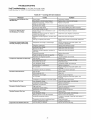
TROUBLESHOOTING .........................
45-47
Unit Troubleshooting ............................
45
EconoMi$er IV Troubleshooting
.................
46
Phase Loss Protection ..........................
47
UNIT START-UP CHECKLIST ..................
CL-I
Manufacturer
Installation and servicing of air-conditioning equipment can
be hazardous due to system pressure and electrical components. Only trained and qualified service personnel should
install, repair, or service ai>conditioning equipment.
Untrained personnel can perform the basic maintenance
functions of cleaning coils and filters and replacing filters. All
other operations should be performed by trained service personnel. When working on ai>conditioning equipment, observe
precautions in the literature, tags and labels attached to the unit,
and other safety precautions that may apply.
Follow all safety codes. Wear safety glasses and work
gloves. Use quenching cloth for unbrazing operations. Have
fire extinguishers available for all brazing operations.
Before performing service or maintenance operations on
unit, turn off main power switch to unit. Electrical shock
could cause personal injury.
Puron (R-410A) refrigerant systems operate at higher pressures than stan&trd R-22 systems. Do not use R-22 service
equipment or components on Puron refrigerant equipment.
If service equipment is not rated for Puron refrigerant,
equipment dmnage or personal injuU may result.
I. Improper installation, adjustment, alteration, service,
or maintenance can cause property &tmage, personal
injury, or loss of life.
2. Do not store or use gasoline or other flammable
vapors and liquids in the vicinity of this or any other
appliance.
I
limits are exceeded, the units will automatically lock the
compressor out of operation. Manual reset will be required
IMPORTANT:
Units have high ambient operating limits. If ]
to restart the compressoc
reserves the right to discontinue, or change at any time, specifications
or designs
PC 111
Form 50PG-5SI
Catalog No, 535-00139
Printed in U,S.A.
CONSIDERATIONS
without notice and without incurring obligations.
Pg 1
8-05
Replaces:
New
INSTALLATION
Step 1 --
Plan for Unit Location
-- Select a location for the unit and its support system (curb or other) that
provides minimum clearances required for safety, unit performance and service access below, around and above unit as
specified in unit drawings. Consider also the effect of adjacent
units.
Do not install unit in an indoor location. Do not locate air
inlets near exhaust vents or other sources of contaminated air.
Although unit is weatherproof, guard against water fiom higher
level runoff and overhangs.
Select a unit mounting system that provides adequate height
to allow installation of condensate trap per requirements. Refer
to Step 6 -- Install External Trap for Condensate Drain for
required trap dimensions.
ROOF MOUNT -- Check building codes for weight distribution requirements. Unit operating weight is shown in Table 1.
Step 2 --
Provide
Unit Support
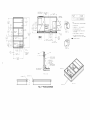
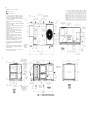
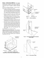
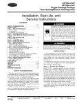
ROOF CURB -- Assemble or install accessory roof curb in
accordance with instructions shipped with this accessory. See
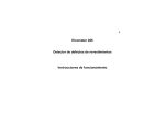
Fig. 1. Install insulation, cant strips, roofing, and counter flashing as shown. DuctwoN can be inst_dled to roof curb before unit
is set in place. DuctwoN must be attached to curb and not to the
unit. Curb must be level. This is necessary to permit unit drain to
fimction properly. Unit leveling tolerance is _+J/l_, in. per linem
fl in any direction. Refer to Accessory Roof Curb Installation
Instructions for additional information as required. When accesso U roof curb is used, unit may be installed on class A, B, or C
roof covering materi_d. CmTier roof curb accessories are for flat
roofs or slab mounting.
IMPORTANT: The gasketing of the unit to the roof curb is
critical for a watertight seal. Install gasket with the roof
curb as shown in Fig. 1. Improperly applied gasket can also
result in air leaks and poor unit performance. Do not slide
unit to position on roof curb.
ALTERNATE UNIT SUPPORTWhen a curb cannot be
used, install unit on a noncombustible
surface. Support unit
with sleepel.s, using unit curb support area. If sleepers c_mnot
be used, support long sides of unit with a minimum of 3 equ_flly spaced 4-in. x 4-in. pads on each side.
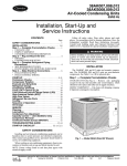
Step 3 -- Rig and Place Unit -- Inspect unit for transportation damage. See Table 1 for physical &_ta. File any claim
with transportation agency.
All panels must be in place when rigging. Damage to unit
may result.
Do not drop unit; keep upright. Use top crate to prevent
sling or cable &_mage. Rollel_ may be used to move unit across
a roof. Level by using unit rail as a reference; leveling tolerance
is + 1/16 in. per linear fl in any direction. See Fig. 2 for additional information. Unit rigging weight is shown in Fig. 2.
Rigging holes are provided in the unit base rails as shown in
Fig. 2. Refer to rigging instructions on unit.
Maintain clearance, per Fig. 3, m'ound and above unit to
provide minimum distance fi_)m combustible materials, proper
airflow, and service access. See Fig. 4 for location on access
panels.
After unit is in position,
sheet.
remove
crating and polyethylene
INSTALLATION
ONTO CURB -- The 50PG units me designed to fit on the accessory full perimeter crab. In either case,
correct placement of the unit onto the curb is critical to operating performance. To aid in correct positioning, place unit on
roof curb to maintain I/4-in. gap between the inside of rail and
roof curb on long sides and a I/z-in. gap between the inside of
rail and roof curb on both duct and condenser ends. Refer to
Fig. 1 and 3, to assure proper duct opening alignment.
NOTE: Before positioning unit onto curb, refer to Step 6 -Install External Trap for Condensate Drain section on page 7
concerning bottom di'ain connection plug.
Do not slide unit to position it when it is sitting on the curb.
Curb gasketing material may be ck_maged and leaks may
result.
SLAB MOUNT (Horizontal Units Only) -- Provide a level
concrete slab that extends a minimum of 6-in. beyond unit cabinet. Install a grovel apron in front of condenser-coil air inlet to
prevent grass and foliage from obstructing airflow.
NOTE: Horizontal
required.
units may also be installed on a roof curb if
50_S
_
os 07
0
2-2
18"
63D
NSIDE
18
7!_6'
[5_8 41
I
IIAI
1 _11 cas_/
2"0'
[610/
i
i
ACCESSORY
i
cRRrcu_SO2O_OO i
CRRrCU_O32A00
i
NO_ES:
i
RO0_ CIJRB ACCESSORY Is SIII?PED UNASS[M_LED
0-3'
6
]8"
SUPPLY AR
I
OPE_ING
3n_'
l
_
OETAI
D
SCALE 11:32
51121
3'
_0
1
s//6
L
OUTSIDE
!
I
/i
I
3 7_8'
(984]
REAR
_"
9/6"
{344 4]
.-I
5
[79
1/8
[/39
5]
_
6]
PANEL
/ [396?
3 15/16:
lt_}l_
03'
{76 71
o EN[N6
_
_"_
1/2"
[/2 7]
o
188h 1 LYKU
DTAIL
SCALE 1 :_2
O6 '
[15_ 9)
i
18
[47_1
(175 O]
_OPEN_NG
[_94
FOF
GASKEi
ELECYR[CAL
SERVICE
4]
o
4
7!$6"
Ill}_
COU_TER FLASHING
(FIELD
SUPPLIED]
0 _/4'
OUTSIDE
ROOFING _ELT
(FIELO
SDPPLIED)
- CANT STRIP
(F;ELO SOPPL[ED)
ROOFING _ATERIAL
N_A]L
(FiELO
SUPPLIED)
R]G[D INSULATION
(F_EL_ SUPPLIED)
1yi>ICA
4 SIDES
SEE
SEE DETAfL
0--\
SEE OE_A[L
\
NOTE
7_
E_
\
SEE
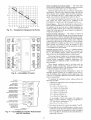
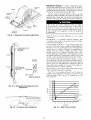
Fig. 1 -- Roof Curb Details
NOTE
?
,_
2
[NSULMEO
3
D[N{NS[ONS IN
4
ROOt C_Rg GALVAN]ZED STEEL
5
ATTACH D_CT_O_ _0 CURB (FLANGES ON _UCT
REST ON CURB)
6
S_RV_C[ CLEARANCE 4 ft ON EAC_ SIDE
7
gOIT HE@S TO BE ON ]NSI9[ OF FLANGE
CLEARANCE IS [1i}
oo7/i6"
Typ ALL CORNERS
PANELS
[
] ARE IN M[LL!_E/ERS
DIRECT!O_ OF AIRFLON
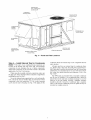
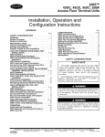
Hook
Detail
center
rigging
shackles
through
holes
in base
rail, as
A. Holes
in base
rails are centered
around
the
of gravity.
prevent
rigging
Use
straps
wooden
from
top
skid,
damaging
when
unit.
rigging,
shown
unit
in
to
UNIT
SIZE
MAX. WEIGHT
03-07
510
kg
PLACE ALL SEAL STRIP
IN PLACE BEFORE PLACING
fUNIT
ON ROOF CORg
SEE
DETAIL A_
Fig. 2 -- 50PG Rigging Label
Step 4 --
Field Fabricate Ductwork-On vertical
units, secure all ducts to roof curb and building structure. Do
not connect ductwork to unit. For horizontal applications, fieldsupplied flanges should be attached to horizontal discharge
openings and all ductwork secured to the flanges. Insulate and
weatherproof all external ductwork, joints, and roof openings
with counter flashing fend mastic in accordance with applicable
codes.
Ducts passing through an unconditioned
space must be
insulated fend covered with a vapor bmriel:
If a plenum return is used with a vertical unit, the return
should be ducted through the roof deck to comply with applicable fire codes.
A minimum clearance is not requiled around ductwork.
Cabinet return-air static pressure (a negative condition) shall
not exceed 0.35 in. wg with economizer or 0.45 in. wg without
economizer.
Step 5 --
Make Unit Duct Connections
VERTICAL SUPPLY/RETURN
CONFIGURATION
-- Unit
is shipped in vertical supply/return
configuration.
Ductwork
openings me shown in Fig. 1 and 3. Attach the ductwork to the
roof curb. Do not attach duct directly to the unit.
For vertical supply and return units, tools or parts could
&op into ductwork and cause fen injury. Install a 90-degree
turn in the leturn ductwork between the unit and the conditioned space. If a 90-degree elbow cannot be installed, then
a grille of sufficient strength and density should be installed
to prevent objects from falling into the conditioned space.
HORIZONTAL SUPPLY/RETURN
APPLICATIONS
-- Unit
can be field-converted from vertical supply/return to horizontal
supply/return.
Remove all screws securing horizontal duct
covers to duct panel. Save panels. Install duct covers in the
vertical duct openings in the basepan with the insulation side
up. Covel.s will drop into openings and can be secured using
field-supplied self-tapping screws. Ductwork can be attached
to duct flanges provided on unit. When securing ductwork to
unit, do not drill in area below bead or above top edge of duct
opening.
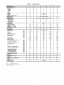
Table 1 -- Physical Data
BASE UNIT 50PG
NOMINAL
CAPACITY
(Tons)
OPERATING WEIGHT
Unit*
Economizer
Vertical
Horizontal
Roof Curb
14-1n.
24-1n.
03
04
05
06
2
3
4
5
6
704
704
775
829
874
40
50
40
50
40
50
40
50
40
50
122
184
122
184
122
184
122
184
(Ib)
122
184
COMPRESSOR
Fully Hermetic
Quantity
OII Type
0,,Number
(oz)
ofRetr,geran,
C,rcu,ts
REFRIGERANT
1
I
1
36
1
I
I
42
1
TYPE
ExpanslonDevlce
Operating
Charge
CONDENSER
(Ib)
TXV
7.3
I
TXV
9.0
Enhanced
Con n..r Ou,
I r
ouant,
,
EVAPORATOR
Nominal Cfm
Maximum Continuous
Bhp
Low
High
Motor Nominal
Rpm
Motor Frame Size
Low
High
Low
High
Fan Rpm Range
Motor Bearing Type
Maximum Fan Rpm
Motor Pulley Pitch Diameter Range (in.)
Low
High
Low
High
Low
High
Low
High
Low
High
Low
High
Low
High
Low
High
Low
High
Low
High
Fan Pulley Pitch Diameter (in.)
BelL.Pitch
Motor Shaft Diameter
Length
(in.)
(in.)
BelL.Type
Pulley Center
Line Distance
MIn. (in.)
Pulley Center
Line Distance
Max. (in.)
Speed Change per Full Turn of
Movable Pulley Flange (rpm)
Movable Pulley Maximum Full
Turns from Closed Position
Factory Pulley Setting (rpm)
Fan Shaft Diameter
at Pulley (in.)
HIGH-PRESSURE
Cutout
Reset (Auto.)
SWITCH
LOW-PRESSURE
Cutout
Reset (Auto.)
SWITCH
FREEZE PROTECTION
Cutout
Reset (Auto.)
RETURN-AIR
FILTERS
OuanUty...Slze
(in.)
--
Thermostatic
Propeller
3500
V8
825
300
I
Copper Tubes, Aluminum
I
1
I
1
I
I
66
1
I
I
56
1
I
Double-Wavy
2...15
9.3
TXV
16.6
Lanced
I
3500
V8
825
300
2...15
9.3
I
I
TXV
19.0
Fins
2...17
12.6
2...17
12.6
2...17
12.6
2...17
12.6
4500
V4
1100
300
4500
V4
1100
300
Fins, Face Spl9
3...15
9.3
I
4...15
9.3
1...12x 9
1...12 x 9
Belt
Belt
8OO
0.85
0.85
1620
48Y
48Y
482-736
656-1001
Ball
2000
1.9-2.9
1.9-2.9
6.8
5.0
V2
V2
49.3
49.3
AX
AX
16.2
16.2
20.2
20.2
48
65
5
5
482
656
¾
1...12 x 9
1...12 x 9
Belt
Belt
1200
0.85
0.85
1620
48Y
48Y
482-736
796-1128
Ball
2000
1.9-2.9
2.4-3.4
6.8
5.2
V2
V2
49.3
49.3
AX
AX
16.2
16.2
20.2
20.2
48
62
5
5
482
796
3/4
Centrifugal Type, Belt Drive
1...12x 9
1...12x 9
Belt
Belt
1600
0.85
1.60/2.40t
1620
48Y
56Y
596-910
828-1173
Ball
2000
1.9-2.9
2.4-3.4
5.5
5.0
V2
_8
49.3
49.3
AX
AX
16.2
16.2
20.2
20.2
59
69
5
5
596
828
¾
1...12 x 9
1...12 x 9
Belt
Belt
2000
0.85/2.4011.60/2.4011725
56Y
56Y
690-978
929-1261
Ball
2000
2.4-3.4
2.8-3.8
6.0
5.2
6/8
%
49.3
49.3
AX
AX
16.2
16.2
20.2
20.2
58
66
5
5
690
929
¾
1...12x 9
1...12x 9
Belt
Belt
2400
2.40
3.10
1725
56Y
56Y
796-1128
1150-1438
Ball
2000
2.4-3.4
4.0-5.0
5.2
6.0
6/8
%
49.3
52.3
AX
AX
16.2
16.2
20.2
20.2
66
58
5
5
796
1150
¾
660 ± 10
505 ± 20
660 ± 10
505 ± 20
660 ± 10
505 ± 20
660 ± 10
505 ± 20
660 ± 10
505 ± 20
(pslg)
(pelg)
THERMOSTAT
40±7
80±7
40±7
80±7
40±7
80±7
40±7
80±7
40±7
80±7
30±5
45±5
30±5
45±5
30±5
45±5
30±5
45±5
30±5
45±5
(F)
4...16x20x2 I
LEGEND
TXV
2...17
12.6
2...15
9.3
Type Drive
Nominal
1...17
12.6
Enhanced
Low
High
Low
High
TXV
15.7
Copper Tubes, Aluminum
---
I
3MA
42
1
2...17
12.6
COIL
Scroll
(Puror'_9 Refrigerant)
1...17
12.6
3500
V8
825
300
Rows...Flns/ln.
Face
Area Isq It)
EVAPORATOR
FAN
OuanUty...Slze
(in.)
1
Copeland
1...17
12.6
FAN
Nominal Cfm (To_l, all fans)
Motor Hp
Nominal Rpm -- High Speed
Nominal Rpm -- Low Speed
I
I
R-410A
COIL
Rows...FIns/In.
Face Area (sq It)
Condenser
B (Inner)
Rows...FIns/In.
Face Area (sq It)
CONDENSER
07
Expansion
*Aluminum evaporator coil/aluminum
tSingle phase/three phase.
Valve
condenser
coil.
4...16x20x2 I
Throwaway
4...16x20x2 I
4...16x20x2 I
4...16x20x2
_OTES
l
D#_RNSIONS iN
2
_
S
I_I"OIRECIIOR
4
ON VERTICAL DISCHARGE UNITS¸ ODCTWORKlO BE AITACHEO
TO ACC{SSORY ROOF CUR8 ONLY EOR HORIZONTAL b[SC_ARG{
UNITS EIELC SUPPLIER FLANGES SHOULC 8E ATTACHED TO
HORIZONTAL DISCHARGE OPENINGS, ANO ALL DUCTWORK S_O_LO
BE ATTARHE_ TO THR EiANGRS
S
b
¢
_
e
!
g
_I
] ARE IN
HILLIMETERS
CENTER OF GRAVITY
i STD
UNiT
i
WEIGHT
8N_T
OF AIR FLOW¸
1
4 15/16"
WITH THE E×BEPTION OF THE CLEARANCE FOR THE CONDENSER
COIL,
A REMOVABLE FENCE OR BARRICADE R{OUIRES NO
CLEARANCE¸
7
D_iTS _AY BE _RSTALLEB OR COMBUSTIBLE FLOORS MADE
PRO_ WOODOR CLASS A, B, OR B ROOF COVERING _AIERIAL
IF SET O_ BASE RAIL
8
EKE VERIICAL CENTER OF BRAViT_ IS
PRO_ THE BOTTOM OF THE BASE RAI_
i6"[45[}
_ALT
CONDENSATE
dRAiN
1"
MINIMUM CLEARANCE (LOCAL COOES OR JbRISDICT_ON _A¥
PREVAIL}:
ON VERTICAL OISCHARGE UNITS, CEEARANCE TO COMBUSTIBLE FOR
FIRST 12" OF CURT TUBE I ¸¸
COTTO_ OF _N!T TO COMBUSTIBLE SURFACES [WHEN NOT USING
CURB1 1 iNCH
BOTTO_ OF BARB RAIL IO CO_B_BT[BLE SURFACES {WHEN NO_
bRiNG CURd) O INCHES
CONBERSER COIL
FOR PROPER AIR FLOW, 36 INCHES
ONE SidE,
IR INCHES THE OTHER THE S!dE GEiTINB
THE
GREATER CLEARANCE _S OPTIONAL¸
OVERHEAD, 60 INCHES TO ASSURE PROPER CONDENSER PAN
OPERATION
BETWEEN UNITS, CONTROL 80X BIBE
42 iN
PER NEC
BETWEEN URI_ AND DNGBOUR_EO SURFACES, CONTROL BOX
SIDE, 36 I_
PER REd
BEiWEER UNIT AND BLOCK OR CONCRETE WALLS ANC OTHER
GROUNDED SBRFARES, CONTROL BOX RIBE_ 42 IN
PER NEC
_ORIZORIAL SUPPLY ANd RETURN ENd, 0 iNCHES¸
6
5 314'
450 3
5
3/4
_4
CORNER
i
CORNER
WE[GRT (A)iWEIGHT
(B>
b i_B
3:9
50PG05 i
/O4
50PGO4 i
/O4
i
Si9
162
[s
i_4D
SBPBO7 i 874
i
B96
20i
9!
i i76 i dO
i _4
_'
DO NOT DRILL IN _
AREA BELOW dEAD
3/4"¸i4
NP/
CONDENSATE _
\
\
---
[7_8
[409
POWER RDPPLYJ
LOW VOLTAGE
KNOCKOUT
(THRU CURB1
[6890_
REAR
SCALE
3 6'
1066 8]
3:32
_'_
1" 8 5/8
[5240]
O
,
I"
dISCONNECT
_
CONVENIENCE 08TLET
/_"RACR
BREAKER
i
i
(OPTIONS/
i
LO_ VOLTAGE
45
O]
/5/16
_'
i
lid'
2B
9
S 5/16"
i442
15703
5]
_-
i
q
CONS
NSER ACCESS
CLEANOUI
PANL
¢0 7!a'
[224]
_/POWER
SUPPLY
5 i/2"
1393
_
BOTTO_
OF UNiT
2 9//D'
i64 Sl
LEFT
SIDE
BONBENSER
1/I
COIL
KNOCKOUT
PO_ER
SUP?LY
4 9/16'
[!_S R]
/
BAROMETRIC RELIEF HOOD
I]RCLUBEB W[TR UNIT)
POWER EXHAUST
O_ERATING POSITION
[OPTION}
7
3
ACCESS COVER
_
i/DO
2 ¸¸B¸i/B_
BRAIN
i CORNER
0:2285
i
255
21
314':
[655 21
[_NCLUCEB WiTH U_ii
"
i
8]
6]
°'
105
/-4i/8
i
ODiSIDE AIR HOOD -_\
(HOOD EIELD ]NSTALLEB}
/O4 4 _
232
2" 2 i/2':
[6734]
UP FRO_
4 11116'
B5 i R_4 i 97
CORNER C
8101//16
27089
2
1B7
NPT
S/B"
CORNER D
=
4 i/B"
CORNER i
CORNER
WEIGHT (C) iWEIGHT
[B/
,m .;
.a,,
/
6::
RIGHT
SIDE
oo
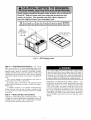
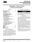
ELECTRICAL
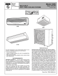
OPTIONS
OUTDOOR
SCREEN
PANEL
CONTROLBOX
AND COMPRESSOR
ACCESS DOOR
\
\
\
\
\
\
\,
INDOOR
MOTOR
ACCESS
/
f
DOOR
AIR
(HIDDEN)
\\
CONDENSER
\
\
ACCESS
COIL
PANEL
ECONOMIZER
HOOD
/
BAROMETRIC
RELIEF DAMPER
HOOD
ELECTRIC
HEAT
ACCESS DOOR
/
BASEPAN
FILTER
ACCESS
DOOR
CONNECTIONS
ACCESS
PANEL
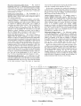
Fig. 4 -- Panel and Filter Locations
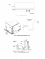
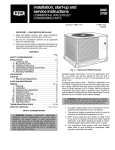
Step 6 -- Install External Trap for Condensate
Drain -- The unit's 3/4-in. condensate dr_dn connections me
condensate drain and external
unit is in place.
located on the bottom and side of the unit. Unit discharge
connections do not determine the use of &'ain connections;
either drain connection can be used with vertical or horizont;fl
applications. See Fig. 3 for locations.
All units must have an external trap for condensate drainage. Install a trap at least 4-in. deep and protect against fieezeup. If drain line is installed downstream from the external trap,
pitch the line away from the unit fit 1-in. per 10 ft of run. Do not
use a pipe size smaller than the unit connection (3/4-in.). See
Fig. 6 and 7.
When using the standard side &'ain connection, make sure
the plug (red) in the alternate bottom connection is tight before
installing the unit. See Fig. 5.
To use the bottom drfdn connection for a roof curb installation, relocate the factou-installed
plug (red) from the bottom
connection to the side connection. A l/2-in, socket extension
can be used to remove the plug. See Fig. 5. The piping for the
trap can be completed
The 50PG units are provided with a removable
pan for ease of cleaning. It is recommended
that
placed between the unit find condensate drainage
removal of the pan during servicing. Adequate
should be allowed if removal of condensate pan
Allow 54 in. between condensate pan access panel
struction for complete lemoval.
after the
condensate
a union be
to ease the
clem'ance
is requiled.
and any ob-
l
SIDE DRAIN
PLUG
__\
\
\ \_/_
\ \
\
\
\ \
\
\
\
\ \
\
\ \
\
\\\\\\\
\
BOTTOM DRAIN
PLUG
Fig. 5 -- Condensate Drain Pan
OPTIONAL
UNIONS
TO ALLOW FOR CONDENSATE
PAN REMOVAL
J
CONDENSATE
PAN ACCESS
PANEL
Fig. 6 -- External Trap for Condensate Drain
.,.,.u..,To.
\
OPEN
2" MIN
VENT
/
I
I I
I
III
I11
_FSEE
NOTE
DRAIN
_
I
I
_
_
")
> /
DRAIN
PLUG
NOTE: Trap should be deep enough to offset maximum
difference. A 4-in. trap is recommended.
=
_,,ROOF
CURB
unit static
Fig. 7 -- Condensate Drain Piping Details
Step 7 --
Make Electrical
Connections
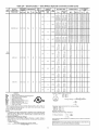
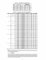
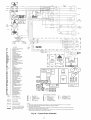
FIELD POWER SUPPLY -- All 2081230-v units are factory
wired for 230-v power supply. If the 2081230-v unit is to be
connected to a 208-v power supply, the transformer must be mwired by moving the black wire with the l/4-in, female quick
connect from the 230-volt connection and moving to the
200-volt l/4-in, m_de temfinal on the prma U side of the
transfonnel:
Refer to unit label diagram for additional infonnaion.
All field wirng must comply with NEC (National Electrical
Code) and local codes. Size wire based on MCA (Minimum
Circuit Amps) on the unit informaive plae. Leads am provided
for field wire connections. Use UL (Underwrters' Laboratores) approved copper/aluminum connectol:
When installing units, provide safety disconnect per NEC
Article 440 or local codes. For non-lused disconnects, size the
disconnect according to the sizing data provided in the electrical daa tables. If a fused disconnect is used, determine the
minimum size for the switch based on the disconnect sizing
data provided in the electrical data tables and then coordinate
the disconnect housing size to accommodate the Maximum
Overcurrent Protection (MOCP) device size as marked on the
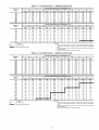
unit informative plate. See Tables 2A and 2B.
See Fig. 8 for power wiring connection to unit leads and
equipment ground.
Route power and ground lines through control box end
panel or unit basepan (see Fig. 3) to connections as shown on
unit wiring diagram and Fig. 8. Make sure that there is a
watertight seal when penetrating the cabinet. Factory leads
may be wired directly to the disconnect.
FIELD CONTROL WIRING -- Unit can be controlled with
a cmrer-approved accessoly thermostat. Inst_dl thermostat according to the inst_dlation instructions included with accessory.
Ix_cate thermostat assembly on a solid interior wall in the
conditioned space to sense average temperature.
Route fllermostat cable or equivalent single leads of colored
wire from subbase terminals through conduit into unit to
low-voltage connections as shown on unit label wiring diagram
and in Fig. 9.
If bottom entU is used, seal the hole in the grommet of the
control box with RTV se_dant.
NOTE: For wire runs up to 50 It, use no. 18 AWG (American
Wire Gage) insulated wire (35 C minimum). For 50 to 75 It,
use no. 16 AWG insulated wire (35 C minimum). For over
75 It, use no. 14 AWG insulated wire (35 C Minimum). All
wire larger than no. 18 AWG cannot be directly connected at
the thermostat and will require a junction box and splice at the
thermostat.
Set heat anticipator settings as follows:
VOLTAGE
All
STAGE 1 AND 2
(Wl AND W2) ON
0.4
(Wl) ON
STAGE
0.2 1
Settings may be changed slightly to provide a greater degree
of comfort for a particulm installation.
C.A1
FIELD
,=_
FACTORY
POWER
,__
POWER
F--
WIRING
The correct power phasing is critical to the operation of the
scroll compressors. An incorrect phasing will result in an
alarm being generated and compressor operation lockout.
Should this occur, power phase correction must be made to
the incoming powel: Damage to compressor could result.
WIRING
Om
(DO-
EQUIP GND
LEGEND
Unit cabinet must have an uninterrupted, unbroken electrical ground to minimize the possibility of personal injury if
an electrical fault should occm: This ground may consist of
electrcal wire connected to unit ground lug in control compartment, or conduit approved for electrical ground when
installed in accordance with NEC; ANSI/NFPA (American
National Standards Institute/Natiomd Fire Protection Association), latest edition, and local electric_d codes. Failure to
follow this wmning could result in the installer being liable
for personal injury of others.
Field wiring must conform to temperature limitations for
type "T" wire. All field wiring must comply with NEC and
local requirements.
Operating voltage to compressor must be within voltage
range indicated on unit nameplate. On 3-phase units, voltages
between phases must be balanced within 2%.
Unit failure as a result of operation on improper line voltage
or excessive phase imbalance constitutes abuse and may cause
damage to electrical components.
C.A1
EQUIP
GND
NEC
-----
Compressor Contactor (A1)
Equipment
Ground
National Electrical Code
NOTE: The maximum
wire size for C.A1 is 2/0.
Fig. 8 -- Field Power Wiring Connections
THERMOSTAT
REMOVABLE
ASSEMBLY
JUMPER
I
[_
TB1 I
I
[]
I
[]
I
I
I
[]
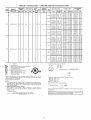
Fig. 9 -- Field Control Thermostat Wiring
I
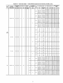
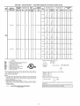
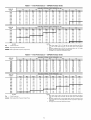
Table2A-UNIT
50PG
NOMINAL
POWER SUPPLY
Volts-Ph-Hz
03
208/230-1-60
VOLTAGE
RANGE
Min
187
Max
253
Electrical Data -- Units Without Optional Convenience Outlet
COMPRESSOR
RLA
12.8
LRA
60
OFM
FLA
FLA
Qty (ea)
1
1.0
IFM
FLA
POWER
EXHAUST
FLA
(ea)
IFM
TYPE
283
18.4
83
1
1.0
FLA
LRA
2,3/ 3.0
3.8/
5.0
5.6/ 7.8
7.5/10.0
22/22
22/22
26/29
36/40
46/52
74/74
74/74
74/74
74/74
74/74
ALT
-10.8/12.5
17.3/20.0
26.0/30.0
34.7/40.0
-2.3/ 3.0
3.8/
5.0
5.6/ 7.8
7.5/10.0
21.9/21.9
21.9/21.9
27.8/31.1
38.6/43.6
49.5/56.1
25/25
28/25
30/35
40/45
80/60
22/22
22/22
26/29
36/40
46/52
74/74
74/74
74/74
74/74
74/74
STD
-10.8/12.5
17.3/20.0
26,0/30.0
34.7/40.0
-2.3/ 3.0
3.8/
5.0
8,6/ 7,8
7.5/10.0
23.3/23.3
23.3/23.8
29.5/32.9
40.4/48,4
51.3/57.9
28/25
28/28
30/35
45/80
60/60
23/23
23/23
27/30
37/42
47/53
76/76
76/76
76/76
76/76
76/76
ALT
-10.8/12.5
17.3/20.0
26.0/30.0
34.7/40.0
-2.3/ 3.0
3.8/
8.0
8.6/ 7.8
7.5/10.0
23.3/23.3
23.3/23.8
29.5/32.9
40.4/48.4
51.3/57.9
28/25
28/25
30/35
45/80
60/60
23/23
23/23
27/30
37/42
47/53
76/76
76/76
76/76
76/76
76/76
-10.8/12.5
-2.3/ 3.0
28.2/25.2
28.2/28.2
30/30
30/30
24/24
24/24
97/97
97/97
17.3/20.0
26.0/30.0
34.7/40.0
52.0/60.0
3.8/
8.0
8.6/ 7.5
7.8/10.0
11.3/15.0
27.8/31.1
38.6/43.6
49.5/56.1
71.1/81.1
30/35
40/48
50/60
80/90
26/29
36/40
46/52
65/75
97/97
97/97
97/97
97/97
-10.8/12.5
17.3/20.0
26.0/30.0
-2.3/ 3.0
3.8/
8.0
8.6/ 7.5
28.2/25.2
25.2/25.2
27.8/31.1
38.6/43.6
30/30
30/30
30/35
40/48
24/24
24/24
26/29
36/40
97/97
97/97
97/97
97/97
49.5/86.1
71.1/81.1
50/60
80/90
46/82
65/75
97/97
97/97
26.6/26.6
26.6/26.6
29.5/32.9
40.4/45.4
30/30
30/30
30/35
45/80
26/26
26/26
27/30
37/42
99/99
99/99
99/99
99/99
51.3/87.9
72.9/82.9
60/60
80/90
47/53
67/76
99/99
99/99
26.6/26.6
26.6/26.6
29.5/32.9
40.4/48.4
30/30
30/30
30/35
45/50
26/26
26/26
27/30
37/42
99/99
99/99
99/99
99/99
51.3/87.9
72.9/82.9
60/60
80/90
47/53
67/76
99/99
99/99
STD
4.9
34.7/40.0
52.0/60.0
4.9
STD
-10.8/12.5
17.3/20.0
26.0/30.0
34.7/40.0
52.0/60.0
1.4
ALT
-10.8/12.5
17.3/20.0
26.0/30.0
34.7/40.0
52.0/60.0
LEGEND
FLA
HACR
IFM
LRA
MCA
MOCP
NEC
OFM
RLA
----------
Nominal
kW*
25/25
28/28
30/35
40/45
80/60
ALT
187
--
7.5/10.0
11.3/15.0
-2.3/ 3.0
3.8/
8.0
5.6/ 7.5
7.5/10.0
11.3/18.0
-2.3/ 3.0
3.8/
5.0
5.6/ 7.5
7.5/10.0
11.3/15.0
MCA
Example: Supply voltage is 230-3-60.
A a c
AB = 224 v
Full Load Amps
Heating, Air Conditioning and Refrigeration
Indoor (Evaporator) Fan Motor
Locked Rotor Amps
Minimum Circuit Amps
Maximum Overcurrent Protection
National Electrical Code
Outdoor (Condenser) Fan Motor
Rated Load Amps
AC = 226 v
224
(_
+ 231
BC =Average
231 v Voltage -
+ 226
3
681
=-=
*Heater capacity (kW) is based on heater voltage of 208 v, 240 v, 480 v or
600 v. If power distribution voltage to unit varies from rated heater voltage,
heater kW will vary accordingly.
tFuse or HACR circuit breaker.
NOTES:
1. In compliance with NEC requirements for multimotor and combination load
equipment (refer to NEC Articles 430 and 440), the overcurrent protective
device for the unit shall be fuse or HACR breaker. Canadian units may be
fuse or circuit breaker.
2. Unbalanced 3-Phase Supply Voltage
Never operate a motor where a phase imbalance in supply voltage is
greater than 2%. Use the following formula to determine the percent of
voltage imbalance.
% Voltage Imbalance
= 100 x
DISCONNECT
SIZE
POWER SUPPLY
MOCPt
-10,8/12.5
17.3/20.0
26.0/30.0
34.7/40.0
STD
208/230-1-60
HEAT
21.9/21.9
21.9/21,9
27.8/31.1
38.6/43.6
49.5/56.1
FLA
1.4
04
ELECTRIC
3
227
Determine
(AB) 227
(BC) 231
(AC) 227
Maximum
Determine
maximum deviation from average voltage.
= 224 = 3 v
= 227 = 4 v
= 226 = 1 v
deviation is 4 v.
percent of voltage imbalance.
4
% Voltage Imbalance
= 100 x
22"_7= 1.76%
This amount of phase imbalance
allowable 2%.
max voltage deviation from average voltage
average voltage
is satisfactory
as it is below the maximum
the local
electric
utility
company
I contact
IMPORTANT:
If the
supply
voltage
phaseimmediately.
imbalance
10
1
is more than 2%, 1
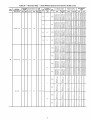
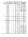
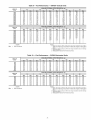
Table 2A -- Electrical Data -- Units Without Optional Convenience Outlet (cont)
UNIT
50PG
NOMINAL
POWER SUPPLY
Volts-Ph-Hz
VOLTAGE
RANGE
Min
208/230-3-60
187
Max
253
COMPRESSOR
RLA
11.5
LRA
77
OFM
FLA
Qty
1
FLA
(ea)
1.0
IFM
FLA
POWER
EXHAUST
FLA
ELECTRIC
TYPE
506
5.1
35
1
0.5
MOCPt
FLA
LRA
STD
28/25
28/25
25/25
25/30
35/40
48/50
20/20
20/20
20/20
23/26
29/32
40/48
91/91
91/91
91/91
91/91
91/91
91/91
ALT
-6.3/ 7.2
10.0/11.5
18.0/17.3
20.0/23.1
30.0/34.6
-2.3/
3.0
3.8/
5.0
5.6/
7.5
7.8/10.0
11.3/18.0
20.3/20.3
20.3/20.3
20.3/20.5
24.9/27.8
31.1/35.0
43.6/49.4
25/25
28/28
28/28
25/30
38/40
45/50
20/20
20/20
20/20
23/26
29/32
40/45
91/91
91/91
91/91
91/91
91/91
91/91
STD
-6.3/ 7.2
10.0/11.5
15.0/17.3
20.0/23.1
30.0/34.6
-2.3/
3.0
3.8/
5.0
5.6/
7.5
7.5/10.0
11.3/15.0
21.7/21.7
21.7/21.7
21.7/22.3
26.6/29.8
32.9/36.8
45.4/51.1
25/25
28/25
28/25
30/30
35/40
50/60
22/22
22/22
22/22
24/27
30/34
42/47
93/93
93/93
93/93
93/93
93/93
93/93
ALT
-6.3/ 7.2
10.0/11.8
18.0/17.3
20.0/23.1
30.0/34.6
-2.3/
3.0
3.8/
5.0
5.6/
7.8
7.8/10.0
11.3/15.0
21.7/21.7
21.7/21.7
21,7/22.3
26.6/29.5
32.9/36.8
45.4/51.1
28/25
28/28
28/28
30/30
35/40
50/60
22/22
22/22
22/22
24/27
30/34
42/47
93/93
93/93
93/93
93/93
93/93
93/93
STD
-3.5
5.8
8.7
11.5
17.3
-3.0
5.0
7.5
10.0
15.0
9.0
9.0
9.9
13.5
17.0
24.3
15
15
15
15
20
25
9
9
9
12
16
22
42
42
42
42
42
42
ALT
-3.5
5.8
8.7
11.5
17.3
-3.0
5.0
7.5
10.0
15.0
9.0
9.0
9.9
13.5
17.0
24.3
15
15
15
15
20
25
9
9
9
12
16
22
42
42
42
42
42
42
STD
-3.5
5.8
8.7
11.5
17.3
-3.0
5.0
7.5
10.0
15.0
9.6
9.6
10.6
14.3
17.8
25.0
15
15
15
15
20
30
10
10
10
13
16
23
43
43
43
43
43
43
ALT
-3.5
5.8
8.7
11.5
17.3
-3.0
5.0
7.5
10.0
15.0
9.6
9.6
10.6
14.3
17.8
25.0
15
15
15
15
20
30
10
10
10
13
16
23
43
43
43
43
43
43
STD
-9.2
13.9
-10.0
15.0
8.0
14.1
20.0
15
15
25
8
13
18
37
37
37
ALT
-9.2
13.9
-10.0
15.0
8.0
14.1
20.0
15
15
25
8
13
18
37
37
37
STD
-9.2
13.9
-10.0
15.0
9.4
15.9
21.8
15
20
25
10
15
20
39
39
39
ALT
-9,2
13,9
-10,0
15,0
9.4
15.9
21.8
15
20
25
10
15
20
39
39
39
30/30
30/30
123/123
123/123
4.9
2.1
518
633
4.3
31
1
0.5
2.1
1.4
O5
208/230-1-60
187
253
20.5
109
1
FLA
Nominal
kW*
MCA
DISCONNECT
SIZE
20.3/20.3
20.3/20.3
20.3/20.5
24.9/27.8
31.1/35.0
43.6/49.4
0.6
575-3-60
SUPPLY
-2.3/
3.0
3.8/
5.0
5.6/
7.5
7.5/10.0
11.3/15.0
O4
(cont)
414
POWER
-6.3/ 7.2
10.0/11.8
15.0/17.3
20.0/23.1
30.0/34.6
(ea)
1.4
460-3-60
HEAT
IFM
-17.3/20.0
-3.8/ 5.0
31.5/ 31.5
31.5/ 31.5
38/ 35
35/ 35
4.9
STD
26.0/30.0
34.7/40.0
82.0/60.0
69.3/80.0
-17.3/20.0
5.6/ 7.5
7.5/10.0
11.3/15.0
15.0/20.0
-3.8/ 5.0
38.6/ 43.6
49.5/ 56.1
71.1/ 81.1
92.8/106.1
33.6/ 33.6
33.6/ 33.8
40/ 45
50/ 60
80 /90
100/110
38/ 35
38/ 35
36/40
46/52
65/75
85/98
33/ 33
33/ 33
123/123
123/123
123/123
123/123
148/148
148/148
7.0
ALT
26.0/30.0
34.7/40.0
52.0/60.0
69.3/80.0
-17.3/20.0
26.0/30.0
34.7/40.0
82.0/60.0
69.3/80.0
-17.3/20.0
5.6/ 7.5
7.5/10.0
11.3/15.0
15.0/20.0
-3.8/ 5.0
5.6/ 7.5
7.8/10.0
11.3/18.0
15.0/20.0
-3.8/ 5.0
41.3/ 46.3
52.1/ 88.8
73.8/ 83.8
95.4/108.8
32.9/ 32.9
32.9/ 32.9
40.4/ 45.4
51.3/ 57.9
72.9/ 82.9
94.8/107.9
35.0/ 35.5
35.0/ 35.5
48/ 50
60/ 60
80/ 90
100/110
38/ 35
38/ 35
48/ 50
60/ 60
80/ 90
100/110
40/ 40
40/ 40
38/ 43
48/ 54
68/ 77
88/100
32/32
32/32
37/42
47/53
67/76
87/99
34/ 34
34/ 34
148/148
148/148
148/148
148/148
128/125
128/125
128/125
128/125
128/125
128/125
150/150
150/150
26.0/30.0
34.7/40.0
52.0/60.0
69.3/80.0
5.6/ 7.5
7.5/10.0
11.3/15.0
15.0/20.0
43.0/ 48.0
53.9/ 60.5
75.8/ 85.5
97.1/110.5
45/ 50
60/ 70
80/ 90
100/125
40/ 44
50/ 56
69/ 79
89/102
150/150
150/150
150/150
150/150
1.0
4.9
1.4
STD
7.0
1.4
ALT
1!
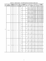
Table 2A -- Electrical Data -- Units Without Optional Convenience Outlet (cont)
UNIT
50PG
NOMINAL
POWER SUPPLY
Volts-Ph-Hz
VOLTAGE
RANGE
Min
Max
COMPRESSOR
RLA
LRA
OFM
FLA
FLA
Qty (ea)
IFM
FLA
POWER
EXHAUST
FLA
(ea)
4.9
5,2
208/230-3-60
187
253
14.6
91
1
878-3-60
414
518
506
633
7.1
5.1
46
1
34
1
ELECTRIC
FLA
HEAT
STD
10.0/11.5
15.0/17.3
20.0/23.1
30.0/34.6
40.0/46.2
3.8/ 5.0
5.6/ 7.5
7.5/10.0
11.3/18.0
15.0/20.0
ALT
10.0/11.5
15.0/17.3
20.0/23.1
30.0/34.6
40.0/46.2
3.8/ 8.0
5.6/ 7.5
7.5/10.0
11.3/15.0
15.0/20.0
4,9
1.4
STD
10.0/11.5
15.0/17.3
20.0/23.1
30.0/34.6
40.0/46.2
3.8/ 8.0
5.6/ 7.8
7.8/10.0
11.3/15.0
15.0/20.0
5.2
1.4
ALT
10.0/11.5
15.0/17.3
20.0/23.1
30.0/34.6
40.0/46.2
3.8/ 8.0
5.6/ 7.5
7.5/10.0
11.3/15.0
15.0/20.0
2.1
STD
2.6
ALT
5.8
5.0
8.7
11.8
17.3
23.1
7.8
10.0
15.0
20.0
5.8
8.7
11.8
17.3
23.1
5.0
7.5
10.0
15.0
20.0
5.8
5.0
8.7
11.5
17.3
23.1
7.8
10.0
15.0
20.0
0.5
2.1
0.6
STD
5.8
5.0
2.6
0.6
ALT
8.7
11.5
17.3
23.1
7.5
10.0
15.0
20.0
2.1
STD
9.2
13.9
18.5
10.0
15.0
20.0
2.0
ALT
9.2
13.9
18.5
10.0
15.0
20.0
0.5
2.1
1.4
STD
9.2
13.9
18.5
10.0
15.0
20.0
2.0
1.4
ALT
9.2
13.9
18.5
10.0
15.0
20.0
LEGEND
POWER SUPPLY
Nominal
kW*
1.0
05
(cont)
460-3-60
IFM
TYPE
DISCONNECT
SIZE
MCA
MOCPt
FLA
LRA
24.2/24.2
24.2/24,2
24.9/27,8
31.1/35.0
43.6/49.4
56.1/63.9
24.5/24.5
24.5/24.5
25.3/28.1
31.5/35.4
44.0/49,8
56.5/84,3
25.8/25.6
25.6/25.6
26.6/29.5
32.9/36,8
45.4/51.1
57.9/65.6
25,9/25.9
25.9/25.9
27.0/29.9
33.3/37.1
45.8/51.5
58.3/68.0
11.5
11.5
13.5
17.0
24.3
31.5
12.0
12.0
14.1
17.8
24.9
32.1
12.1
12.1
14.3
17.8
25.0
32.3
12.6
12.6
14.9
18.4
25.6
32.9
9.0
14.1
20.0
25.8
8.9
14.0
19.9
25.6
10.4
15.9
21.8
27.5
10.3
15.8
21.6
27.4
25/25
25/25
25/30
35/40
45/50
60/70
25/25
25/25
30/30
35/40
45/50
60/70
30/30
30/30
30/30
35/40
50/60
60/70
30/30
30/30
30/30
35/40
50/60
60/70
15
15
15
20
25
35
15
15
15
20
25
35
15
15
15
20
30
35
15
15
15
20
30
35
15
15
25
30
15
15
20
30
15
20
28
30
15
20
28
30
24/24
24/24
24/26
29/32
40/45
52/59
24/24
24/24
24/26
29/33
40/46
52/59
25/25
25/25
25/27
30/34
42/47
53/60
28/26
26/26
26/27
31/34
42/47
54/61
11
11
12
16
22
29
12
12
13
16
23
30
12
12
13
16
23
30
12
12
14
17
24
30
9
13
18
24
9
13
18
24
10
15
20
25
10
14
20
25
105/105
105/105
105/105
105/105
105/105
105/105
123/123
123/123
123/123
123/123
123/123
123/123
107/107
107/107
107/107
107/107
107/107
107/107
125/125
125/125
125/125
125/125
125/125
125/125
53
53
53
53
53
53
62
62
62
62
62
62
54
54
54
54
54
54
63
63
63
63
63
63
40
40
40
40
46
46
46
46
42
42
42
42
48
48
48
48
Example: Supply voltage is 230-3-60.
FLA
HACR
---
Full Load Amps
Heating, Air Conditioning
A
LRA
MCA
MOCP
IFM
NEC
OFM
RLA
--------
Locked Rotor Amps
Minimum Circuit Amps
Maximum Overcurrent Protection
Indoor
Fan Motor
National(Evaporator)
Electrical Code
Outdoor (Condenser) Fan Motor
Rated Load Amps
B c
and Refrigeration
AB = 224 v
AC = 226 v
(_
C @
BC =Average
231 v Voltage -
US
=--
224 + 231 + 226
3
681
3
= 227
*Heater capacity (kW) is based on heater voltage of 208 v, 240 v, 480 v or
600 v. If power distribution voltage to unit varies from rated heater voltage,
heater kW will vary accordingly.
l-Fuse or HACR circuit breaker.
NOTES:
1. In compliance with NEC requirements for multimeter and combination load
equipment (refer to NEC Articles 430 and 440), the evercurrent protective
device for the unit shall be fuse or HACR breaker. Canadian units may be
fuse or circuit breaker.
2. Unbalanced
3-Phase Supply Voltage
Never operate a motor where a phase imbalance in supply voltage is
greater than 2%. Use the following formula to determine the percent of
voltage imbalance.
% Voltage Imbalance
= 100 x
max voltage deviation from average voltage
average voltage
Determine
(AB) 227
(BC) 231
(AC) 227
Maximum
Determine
maximum deviation from average voltage.
- 224 = 3 v
- 227 = 4 v
- 226 = 1 v
deviation is 4 v.
percent of voltage imbalance.
4
% Voltage Imbalance
= 100 x
22"_7= 1.76%
This amount of phase imbalance
allowable 2%.
is satisfactory
as it is below the maximum
the local
electric
utility
company
I contact
IMPORTANT:
If the
supply
voltage
phaseimmediately.
imbalance
]2
1
is more than 2%, 1
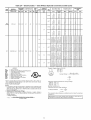
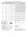
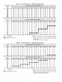
Table 2A -- Electrical Data -- Units Without Optional Convenience Outlet (cont)
UNIT
50PG
NOMINAL
POWER SUPPLY
Volts-Ph-Hz
208/230-1-60
VOLTAGE
RANGE
Min
187
Max
253
COMPRESSOR
RLA
26.9
LRA
145
OFM
FLA
FLA
Qty (ea)
1
IFM
FLA
POWER
EXHAUST
FLA
(ea)
IFM
TYPE
4.9
STD
7.0
ALT
1.5
4.9
1.4
STD
7.0
1.4
ALT
STD
ALT
O6
208/230-3-60
187
253
17.6
123
1
1.5
5.2
STD
1.4
ALT
STD
ALT
460-3-60
414
506
7.7
50
1
0.8
2.6
STD
0.6
ALT
13
ELECTRIC
FLA
-17.3/ 20.0
26.0/ 30.0
34.7/ 40.0
52.0/ 60.0
69.3/ 80.0
86.7/100.0
-17.3/ 20.0
26.0/ 30.0
34.7/ 40.0
52.0/ 60.0
69.3/ 80.0
86.7/100.0
-17.3/ 20.0
26.0/ 30.0
34.7/ 40.0
52.0/ 60.0
69.3/ 80.0
86.7/100.0
-17.3/ 20.0
26.0/ 30.0
34.7/ 40.0
82.0/ 60.0
69.3/ 80.0
86.7/100.0
-10.0/11.5
15.0/17.3
20.0/23.1
30.0/34.6
40.0/46.2
50.0/87.7
-10.0/11.5
15.0/17.3
20.0/23.1
30.0/34.6
40.0/46.2
50.0/57.7
-10.0/11.8
15.0/17.3
20.0/23.1
30.0/34.6
40.0/46.2
50.0/57.7
-10.0/11.5
15.0/17.3
20.0/23.1
30.0/34.6
40.0/46.2
50.0/87.7
-5.8
8.7
11.5
17.3
23.1
28.9
-5.8
8.7
11.5
17.3
23.1
28.9
-5.8
8.7
11.5
17.3
23.1
28.9
-5.8
8.7
11.5
17.3
23.1
28.9
HEAT
Nominal
kW*
-3.8/ 5.0
5.6/ 7.8
7.5/10.0
11.3/15.0
15.0/20.0
18.8/25.0
-3.8/ 5.0
5.6/ 7.5
7.5/10.0
11.3/18.0
15.0/20.0
18.8/25.0
-3.8/ 5.0
5.6/ 7.8
7,5/10.0
11.3/15.0
15.0/20.0
18.8/25.0
-3.8/ 5.0
5.6/ 7.5
7.5/10.0
11.3/15.0
15.0/20.0
18.8/25.0
-3.8/ 5.0
5.6/ 7.5
7.5/10.0
11.3/15.0
15.0/20.0
18.8/25.0
-3.8/ 5.0
5.6/ 7.5
7.5/10.0
11.3/15.0
15.0/20.0
18.8/25.0
-3.8/ 5.0
5.6/ 7.5
7.5/10.0
11.3/15.0
15.0/20.0
18.8/25.0
-3.8/ 5.0
5.6/ 7.5
7.5/10.0
11.3/15.0
15.0/20.0
18.8/25.0
-5.0
7.5
10.0
15.0
20.0
25.0
-5.0
7.5
10.0
18.0
20.0
25.0
-5.0
7.5
10.0
15.0
20.0
25.0
-5.0
7.5
10.0
15.0
20.0
28.0
POWER SUPPLY
MCA
40.0/ 40.0
40.0/ 40.0
40.0/ 43.6
49.5/ 56.1
71.1/ 81.1
92.8/106.1
114.5/131.1
42.1/ 42.1
42.1/ 42,1
42.1/ 46.3
52.1/ 58.8
73.8/ 83.8
95.4/108.8
117.1/133.8
41.4/ 41.4
41.4/ 41.4
41.4/ 45.4
51.3/ 57.9
72.9/ 82.9
94.5/107.9
116.3/132.9
43.5/ 43.5
43.5/ 43.5
43.5/ 48.0
53.9/ 60.5
75.8/ 85.5
97.1/110.5
118.9/135.5
28.7/28.7
28.7/28.7
28.7/28.7
31,5/35.4
44.0/49.8
56.8/64.3
69.0/78.6
28.7/28.7
28.7/28.7
28.7/28.7
31.5/35.4
44.0/49,8
56.8/64.3
69.0/78.6
30.1/30.1
30.1/30.1
30.1/30.1
33.3/37.1
45.8/51.8
58.3/66.0
70.8/80.4
30.1/30.1
30.1/30.1
30.1/30.1
33.3/37.1
45.8/51.5
58.3/66.0
70.8/80.4
13.0
13.0
14.1
17.6
24.9
32.1
39.4
13.0
13.0
14.1
17.6
24.9
32.1
39.4
13.6
13.6
14.9
18.4
25.6
32.9
40.1
13.6
13.6
14.9
18.4
25.6
32.9
40.1
MOCPt
45/ 45
48/ 45
45/ 45
50/ 60
80/ 90
100/110
125/150
45/ 45
45/ 45
45/ 50
60/ 60
80/ 90
100/110
125/150
45/ 45
45/ 45
45/ 50
60/ 60
80/ 90
100/110
128/150
50/ 50
50/ 50
50/ 50
60/ 70
80/ 90
100/125
125/150
30/30
30/30
30/30
35/40
45/50
60/70
70/80
30/30
30/30
30/30
35/40
45/50
60/70
70/80
35/35
38/35
38/35
35/40
50/60
60/70
80/90
38/35
35/35
38/35
35/40
50/60
60/70
80/90
15
15
15
20
25
35
40
15
15
15
20
25
35
40
15
15
15
20
30
35
45
15
15
15
20
30
35
45
DISCONNECT
SIZE
FLA
LRA
38/ 38
38/ 38
38/ 40
46/ 52
65/ 75
85/ 98
105/121
41/ 41
41/ 41
41/ 43
48/ 54
68/ 77
88/100
108/123
40/ 40
40/ 40
40/ 42
47/ 53
67/ 76
87/ 99
107/122
42/ 42
42/ 42
42/ 44
50/ 56
69/ 79
89/102
109/125
28/28
28/28
28/28
29/33
40/46
52/59
63/72
28/28
28/28
28/28
29/33
40/46
52/59
63/72
30/30
30/30
30/30
31/34
42/47
54/61
65/74
30/30
30/30
30/30
31/34
42/47
54/61
65/74
13
13
13
16
23
30
36
13
13
13
16
23
30
36
13
13
14
17
24
30
37
13
13
14
17
24
30
37
160/160
160/160
160/160
160/160
160/160
160/160
160/160
185/185
185/185
185/185
185/185
185/185
185/185
185/185
162/162
162/162
162/162
162/162
162/162
162/162
162/162
187/187
187/187
187/187
187/187
187/187
187/187
187/187
156/156
156/156
156/156
156/156
156/156
156/156
156/156
156/156
156/156
156/156
156/156
156/156
156/156
156/156
158/158
158/158
158/158
158/158
158/158
158/158
158/158
158/158
158/158
158/158
158/158
158/158
158/158
158/158
67
67
67
67
67
67
67
67
67
67
67
67
67
67
68
68
68
68
68
68
68
68
68
68
68
68
68
68
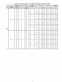
Table 2A -- Electrical Data -- Units Without Optional Convenience Outlet (cont)
UNIT
50PG
NOMINAL
POWER SUPPLY
Volte-Ph-Hz
VOLTAGE
RANGE
Min
Max
COMPRESSOR
RLA
LRA
OFM
FLA
Qty
FLA
(ea)
IFM
POWER
EXHAUST
IFM
FLA
FLA
(ea)
TYPE
STD
ALT
O6
(cont)
575-3-60
518
633
6.1
40
1
0.8
2,0
STD
1.4
ALT
208/230-3-60
O7
187
253
20,5
149
1
5,2
--
STD
7,5
--
ALT
1.5
5,2
1.4
STD
7,5
1.4
ALT
LEGEND
FLA
NACR
IFM
LRA
MCA
MOCP
NEC
OFM
RLA
----------
ELECTRIC
FLA
-9,2
13,9
18.5
23,1
-9,2
13.9
18.5
23,1
-9,2
13.9
18,5
HEAT
POWER SUPPLY
Nominal
kW*
-1O,O
15,0
2O,O
25,0
-1O,O
15.0
2O,O
25,0
-1O,O
15.0
20,0
MCA
MOCPt
FLA
LRA
10,4
14,0
19,9
25,6
31.4
10,4
14,0
19,9
25,6
31.4
11.8
15,8
21,6
27,4
15
15
20
30
35
15
15
20
30
35
15
20
25
30
10
13
18
24
29
10
13
18
24
29
12
14
20
25
53
53
53
53
53
53
53
53
53
53
55
55
55
55
23,1
-9.2
13,9
18,5
23,1
-10,0/11.5
15,0/17.3
20,0/23.1
30,0/34,6
40,0/46.2
50,0/57.7
-10,0/11.5
15,0/17.3
20,0/23.1
30,0/34.6
40,0/46.2
25,0
-1O,O
15,0
20,0
25,0
-3,8/ 5,0
5,6/ 7,5
7.5/10,0
11,3/15.0
15,0/20.0
18,8/25.0
-3,8/ 5,0
5,6/ 7,5
7.5/10,0
11,3/15.0
15,0/20.0
33,1
11.8
15,8
21,6
27,4
33,1
32.3/32,3
32.3/32,3
32.3/32,3
32.3/35.4
44.0/49.8
56.5/64.3
69.0/78,6
34.6/34,6
34.6/34,6
34.6/34,6
34.6/38,3
46.9/52,6
59.4/67,1
35
15
20
25
30
35
35/35
35/35
35/35
35/40
45/50
60/70
70/80
35/35
35/35
35/35
35/40
50/60
60/70
30
12
14
20
25
30
31/31
31/31
31/31
31/33
40/46
52/59
63/72
34/34
34/34
34/34
34/35
43/48
55/62
55
55
55
55
55
55
182/182
182/182
182/182
182/182
182/182
182/182
182/182
208/208
208/208
208/208
208/208
208/208
208/208
50,0/57.7
-10,0/11.5
15,0/17.3
20,0/23.1
30,0/34.6
40,0/46.2
50,0/57.7
-10,0/11.5
15,0/17.3
20,0/23.1
30,0/34,6
40,0/46.2
50,0/57.7
18,8/25.0
-3,8/ 5,0
5,6/ 7,5
7.5/10,0
11,3/15.0
15,0/20.0
18,8/25.0
-3,8/ 5,0
5,6/ 7,5
7.5/10,0
11,3/15.0
15,0/20.0
18,8/25.0
71.9/81,5
33.7/33,7
33.7/33,7
33.7/33,7
33.7/37,1
45.8/51,5
58.3/66,0
70.8/80,4
36.0/36,0
36.0/36,0
36.0/36,0
36.1/40.0
48.6/54.4
61.1/68.9
73.6/83,3
80/90
35/35
35/35
35/35
35/40
50/60
60/70
80/90
40/40
40/40
40/40
40/45
50/60
70/70
80/90
66/75
33/33
33/33
33/33
33/34
42/47
54/61
65/74
36/36
36/36
36/36
36/37
45/50
56/63
68/77
208/208
184/184
184/184
184/184
184/184
184/184
184/184
184/184
210/210
210/210
210/210
210/210
210/210
210/210
210/210
Example: Supply voltage is 230-3-60.
A a C
AB = 224V
Full Load Amps
Heating, Air Conditioning and Refrigeration
Indoor (Evaporator) Fan Motor
Locked Rotor Amps
Minimum Circuit Amps
Maximum Overcurrent Protection
National Electrical Code
Outdoor (Condenser) Fan Motor
Rated Load Amps
AC = 226 v
224 + 231 + 226
3
BC =Average
231 v Voltage -
681
=-=
*Heater capacity (kW) is based on heater voltage of 208 v, 240 v, 480 v or
600 v. If power distribution voltage to unit varies from rated heater voltage,
heater kW will vary accordingly.
l-Fuse or HACR circuit breaker,
NOTES:
1. In compliance with NEC requirements for multimotor and combination load
equipment (refer to NEC Articles 430 and 440), the overcurrent protective
device for the unit shall be fuse or HACR breaker. Canadian units may be
fuse or circuit breaker,
2. Unbalanced 3-Phase Supply Voltage
Never operate a motor where a phase imbalance in supply voltage is
greater than 2%. Use the following formula to determine the percent of
voltage imbalance,
% Voltage Imbalance
= 1OOx
DISCONNECT
SIZE
3
227
Determine
(AB) 227
(BC) 231
(AC) 227
Maximum
Determine
maximum deviation from average voltage.
= 224 = 3 v
= 227 = 4 v
= 226 = 1 v
deviation is 4 v.
percent of voltage imbalance.
4
% Voltage Imbalance
= 100 x
22"_= 1.76%
This amount of phase imbalance
allowable 2%.
max voltage deviation from average voltage
average voltage
is satisfactory
as it is below the maximum
the local
electric
utility
company
I contact
IMPORTANT:
If the
supply
voltage
phaseimmediately.
imbalance
14
l
is more than 2%, 1
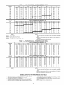
Table 2A -- Electrical Data -- Units Without Optional Convenience Outlet
UNIT
50PG
NOMINAL
POWER
SUPPLY
Volts-Ph-Hz
460-3-60
VOLTAGE
RANGE
Min
414
Max
506
COMPRESSOR
RLA
9.6
LRA
75
OFM
FLA
Qty
1
FLA
(ea)
IFM
POWER
EXHAUST
IFM
FLA
FLA
(ea)
TYPE
2.6
--
STD
3.4
--
ALT
0.8
518
633
7.6
54
1
HEAT
POWER SUPPLY
FLA
-5.8
8.7
11.5
17.3
23.1
28.9
-5.8
8.7
11.5
17.3
23.1
Nominal
kW*
-5.0
7.5
10.0
15.0
20.0
25.0
-5.0
7.5
10.0
15.0
20.0
MCA
15.4
15.4
15.4
17.6
24.9
32.1
39.4
16.2
16.2
16.2
18.6
25.9
33.1
MOCPt
20
20
20
20
25
35
40
20
20
20
20
30
35
28.9
-5.8
8.7
11.5
17.3
23.1
28.9
-5.8
8.7
11.5
17.3
23.1
28.9
-9.2
25.0
-5.0
7.5
10.0
15.0
20.0
25.0
-5.0
7.5
10.0
15.0
20.0
25.0
-10.0
40.4
16.0
16.0
16.0
18.4
25.6
32.9
40.1
16.8
16.8
16.8
19.4
26.6
33.9
41.1
12.3
14.0
45
20
20
20
20
30
35
45
20
20
20
20
30
35
45
15
15
2.6
0.6
STD
3.4
0.6
ALT
2.0
--
STD
13.9
18.5
23.1
27.7
-9.2
15.0
20.0
25.0
30.0
-10.0
19.9
25.6
31.4
37.1
13.1
15.0
20
30
35
40
15
15
2.8
--
ALT
13.9
18.5
23.1
27.7
-9.2
15.0
20.0
25.0
30.0
-10.0
20.9
26.6
32.4
38.1
13.7
15.8
25
30
35
40
15
20
2.0
1.4
STD
13.9
18.5
23.1
27.7
-9.2
15.0
20.0
25.0
30.0
-10.0
21.6
27.4
33.1
38.9
14.5
16.8
25
30
35
40
15
20
2.8
1.4
ALT
13.9
18.5
23.1
27.7
15.0
20.0
25.0
30.0
22.6
28.4
34.1
39.9
25
30
35
40
O7
(cont)
575-3-60
ELECTRIC
0.8
]5
DISCONNECT
SIZE
FLA
LRA
15
15
15
16
23
30
36
16
16
16
17
24
30
37
16
16
16
17
24
30
37
17
17
17
18
24
31
38
12
13
16
24
29
34
13
14
19
24
30
35
14
14
20
25
30
36
14
15
21
26
31
37
92
92
92
92
92
92
92
105
105
105
105
105
105
105
93
93
93
93
93
93
93
106
106
106
106
106
106
106
67
67
67
67
67
67
78
78
76
76
78
78
69
69
69
69
69
69
80
60
60
80
60
80
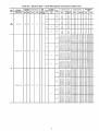
Table 2B -- Electrical Data -- Units With Optional Convenience Outlet
UNIT
50PG
NOMINAL
POWER SUPPLY
Volte-Ph-Hz
VOLTAGE
RANGE
Min
Max
COMPRESSOR
RLA
LRA
OFM
FLA
FLA
Qty (ea)
IFM
FLA
POWER
EXHAUST
FLA
(ea)
IFM
TYPE
STD
ALT
03
208/230-1-60
187
253
12.8
60
1
1.0
4.9
STD
1.4
ALT
STD
ALT
04
208/230-1-60
187
283
18.4
83
1
1.0
4.9
STD
1.4
ALT
LEGEND
FLA
HACR
IFM
LRA
MCA
MOCP
NEC
OFM
RLA
----------
ELECTRIC
HEAT
DISCONNECT
SIZE
POWER SUPPLY
FLA
-10.8/12.5
17.3/20.0
26.0/30.0
34.7/40.0
-10.8/12.5
17.3/20.0
26.0/30.0
34.7/40.0
-10.8/12.5
17.3/20.0
26.0/30.0
34.7/40.0
-10.8/12.5
17.3/20.0
26.0/30.0
34.7/40.0
-10.8/12.5
Nominal
kW*
-2.3/ 3.0
3.8/ 5.0
5.6/ 7.8
7.5/10.0
-2.3/ 3.0
3.8/ 5.0
5.6/ 7.8
7.5/10.0
-2.3/ 3.0
3.8/ 5.0
8.6/ 7.8
7.5/10.0
-2.3/ 3.0
3.8/ 8.0
8.6/ 7.8
7.5/10.0
-2.3/ 3.0
MCA
MOCPt
FLA
LRA
26.7/26.7
26.7/27.8
33.8/37.1
44.6/49.6
55.5/62.1
26.7/26.7
26.7/27.8
33.8/37.1
44.6/49.6
55.5/62.1
28.1/28.1
28.1/29.8
35.5/38.9
46.4/51.4
57.3/63.9
28.1/28.1
28.1/29.5
35.5/38.9
46.4/51.4
57.3/63.9
30.0/30.0
30.0/30.0
30/30
30/30
35/40
45/80
60/70
30/30
30/30
35/40
45/80
60/70
30/30
30/30
40/40
80/60
60/70
30/30
30/30
40/40
80/60
60/70
30/30
30/30
27/27
27/27
31/34
41/46
51/57
27/27
27/27
31/34
41/46
51/57
29/29
29/29
33/36
43/47
53/59
29/29
29/29
33/36
43/47
53/59
30/30
30/30
79/79
79/79
79/79
79/79
79/79
79/79
79/79
79/79
79/79
79/79
81/81
81/81
81/81
81/81
81/81
81/81
81/81
81/81
81/81
81/81
102/102
102/102
17.3/20.0
26.0/30.0
34.7/40.0
52.0/60.0
-10.8/12.5
17.3/20.0
26.0/30.0
34.7/40.0
52.0/60.0
-10.8/12.5
17.3/20.0
26.0/30.0
34.7/40.0
52.0/60.0
-10.8/12.5
17.3/20.0
26.0/30.0
34.7/40.0
52.0/60.0
3.8/ 5.0
5.6/ 7.5
7.5/10.0
11.3/15.0
-2.3/ 3.0
3.8/ 5.0
5.6/ 7.5
7.5/10.0
11.3/15.0
-2.3/ 3.0
3.8/ 5.0
5.6/ 7.5
7.5/10.0
11.3/15.0
-2.3/ 3.0
3.8/ 5.0
5.6/ 7.5
7.5/10.0
11.3/15.0
33.8/37.1
44.6/49.6
55.5/62.1
77.1/87.1
30.0/30.0
30.0/30.0
33.8/37.1
44.6/49.6
55.5/62.1
77.1/87.1
31.4/31.4
31.4/31.4
35.5/38.9
46.4/51.4
57.3/63.9
78.9/88.9
31.4/31.4
31.4/31.4
35.5/38.9
46.4/51.4
57.3/63.9
78.9/88.9
35/40
45/50
60/70
80/90
30/30
30/30
35/40
45/50
60/70
80/90
35/35
35/35
40/40
80/60
60/70
80/90
35/35
35/35
40/40
50/60
60/70
80/90
31/34
41/46
51/57
71/80
30/30
30/30
31/34
41/46
51/57
71/80
32/32
32/32
33/36
43/47
53/59
73/82
32/32
32/32
33/36
43/47
53/59
73/82
102/102
102/102
102/102
102/102
102/102
102/102
102/102
102/102
102/102
102/102
104/104
104/104
104/104
104/104
104/104
104/104
104/104
104/104
104/104
104/104
104/104
104/104
Example: Supply voltage is 230-3-60.
A a c
AB = 224 v
Full Load Amps
Heating, Air Conditioning and Refrigeration
Indoor (Evaporator) Fan Motor
Locked Rotor Amps
Minimum Circuit Amps
Maximum Overcurrent Protection
National Electrical Code
Outdoor (Condenser) Fan Motor
Rated Load Amps
AC = 226 v
224
(_
+ 231
BC =Average
231 v Voltage -
=--
+ 226
3
681
3
= 227
*Heater capacity (kW) is based on heater voltage of 208 v, 240 v, 480 v or
600 v. If power distribution voltage to unit varies from rated heater voltage,
heater kW will vary accordingly.
l-Fuse or HACR circuit breaker.
NOTES:
1. In compliance with NEC requirements for multimotor and combination load
equipment (refer to NEC Articles 430 and 440), the overcurrent protective
device for the unit shall be fuse or HACR breaker. Canadian units may be
fuse or circuit breaker.
2. Unbalanced
3-Phase Supply Voltage
Never operate a motor where a phase imbalance in supply voltage is
greater than 2%. Use the following formula to determine the percent of
voltage imbalance.
% Voltage Imbalance
= 100 x
Determine
(AB) 227
(BC) 231
(AC) 227
Maximum
Determine
maximum deviation from average voltage.
- 224 = 3 v
- 227 = 4 v
- 226 = 1 v
deviation is 4 v.
percent of voltage imbalance.
4
% Voltage Imbalance
= 100 x
22"_= 1.76%
This amount of phase imbalance
allowable 2%.
max voltage deviation from average voltage
average voltage
is satisfactory
as it is below the maximum
contact
the local
electric
utility
company
IMPORTANT:
If the
supply
voltage
phaseimmediately.
imbalance
16
1
is more than 2%, 1
Table 2B -- Electrical Data -- Units With Optional Convenience
UNIT
50PG
NOMINAL
POWER SUPPLY
Volts-Ph-Hz
VOLTAGE
RANGE
Min
Max
COMPRESSOR
RLA
LRA
OFM
FLA
FLA
Qty (ea)
IFM
FLA
POWER
EXHAUST
FLA
(ea)
IFM
TYPE
STD
ALT
208/230-3-60
187
253
11.5
77
1
1.0
4.9
STD
1.4
ALT
STD
O4
(cont)
ALT
460-3-60
414
506
5.1
35
1
0.5
2.1
STD
0.6
ALT
STD
ALT
575-3-60
518
633
4.3
31
1
0.5
2.1
STD
1.4
ALT
O5
208/230-1-60
187
253
20.5
109
1
ELECTRIC
FLA
HEAT
Outlet (cont)
POWER SUPPLY
-6.3/ 7.2
10.0/11.5
18.0/17.3
20.0/23.1
30.0/34.6
-6.3/ 7.2
10.0/11.5
18.0/17.3
20.0/23.1
30.0/34.6
-6.3/ 7.2
10.0/11.5
15.0/17.3
20.0/23.1
30.0/34.6
-6.3/ 7.2
10.0/11.8
18.0/17.3
20.0/23.1
30.0/34.6
-3.5
5,8
8,7
11.5
17.3
-3.5
5,8
8.7
11.5
17.3
-3.5
5.8
8.7
11.5
17.3
-3.5
5.8
8.7
11.5
17.3
-9.2
13.9
-9.2
13.9
-9.2
13.9
-9.2
13.9
-17.3/20.0
Nominal
kW*
-2.3/ 3.0
3.8/ 5.0
5.6/ 7.5
7.8/10.0
11.3/15.0
-2.3/ 3.0
3.8/ 5.0
5.6/ 7.5
7.8/10.0
11.3/18.0
-2.3/ 3.0
3.8/ 5.0
5.6/ 7.5
7.5/10.0
11.3/15.0
-2.3/ 3.0
3.8/ 5.0
5.6/ 7.8
7.8/10.0
11.3/15.0
-3.0
5,0
7,5
10.0
15.0
-3.0
5,0
7.5
10.0
15.0
-3.0
5.0
7.5
10.0
15.0
-3.0
5.0
7.5
10.0
15.0
-10.0
15.0
-10.0
15.0
-10.0
15.0
-10.0
15.0
-3.8/ 5.0
25.1/25.1
28.1/28.1
25.1/26.5
30.9/33.8
37.1/41.0
49.6/55.4
25.1/25.1
28.1/25.1
25.1/26.5
30.9/33.8
37.1/41.0
49.6/85.4
26.8/26.5
26.8/26.8
26.8/28.3
32.6/35.5
38.9/42.8
51.4/57.1
26.8/26.5
26.8/26.5
26.8/28.3
32.6/35.5
38.9/42.8
81.4/57.1
11.2
11.2
12.6
16.3
19.8
27.0
11.2
11.2
12.6
16.3
19.8
27.0
11.8
11.8
13.4
17.0
20.5
27.8
11.8
11.8
13.4
17.0
20.5
27.8
9.7
16.3
22.1
9.7
16.3
22.1
11.1
18.0
23.9
11.1
18.0
23.9
36.3/ 36.3
36.3/ 37.1
MCA
MOCPt
DISCONNECT
SIZE
FLA
LRA
30/30
30/30
30/30
35/35
40/45
50/60
30/30
30/30
30/30
35/35
40/48
50/60
30/30
30/30
30/30
38/40
40/48
60/60
30/30
30/30
30/30
38/40
40/48
60/60
15
15
15
20
20
30
15
15
15
20
20
30
15
15
15
20
25
30
15
15
15
20
25
30
15
20
25
15
20
25
15
20
25
15
20
25
40/ 40
40/ 40
26/26
26/26
26/26
28/31
34/38
46/51
26/26
26/26
26/26
28/31
34/38
46/51
27/27
27/27
27/27
30/33
36/39
47/53
27/27
27/27
27/27
30/33
36/39
47/53
11
11
12
15
18
25
11
11
12
15
18
25
12
12
12
16
19
26
12
12
12
16
19
26
10
15
20
10
15
20
12
17
22
12
17
22
36/ 36
36/ 36
96/96
96/96
96/96
96/96
96/96
96/96
96/96
96/96
96/96
96/96
96/96
96/96
98/98
98/98
98/98
98/98
98/98
98/98
98/98
98/98
98/98
98/98
98/98
98/98
44
44
44
44
44
44
44
44
44
44
44
44
45
45
45
45
45
45
45
45
45
45
45
45
39
39
39
39
39
39
41
41
41
41
41
41
128/128
128/128
4.9
STD
26.0/30.0
34.7/40.0
52.0/60.0
69.3/80.0
-17.3/20.0
5.6/ 7.5
7.8/10.0
11.3/18.0
18.0/20.0
-3.8/ 5.0
44.6/ 49.6
55.5/ 62.1
77.1/ 87.1
98.8/112.1
38.4/ 38.4
38.4/ 39.8
45/ 50
60/ 70
80/ 90
100/125
40/ 40
40/ 40
41/ 46
51/ 87
71/ 80
91/103
38/ 38
38/ 38
128/128
128/128
128/128
128/128
153/153
153/153
7.0
ALT
26.0/30.0
34.7/40.0
52.0/60.0
69.3/80.0
-17.3/20.0
26.0/30.0
34.7/40.0
52.0/60.0
69.3/80.0
-17.3/20.0
5.6/ 7.5
7.5/10.0
11.3/15.0
15.0/20.0
-3.8/ 5.0
5.6/ 7.5
7.5/10.0
11.3/15.0
15.0/20.0
-3.8/ 5.0
47.3/ 52.3
88.1/ 64.8
79.8/ 89.8
101.4/114.8
37.7/ 37.7
37.7/ 38.9
46.4/ 51.4
57.3/ 63.9
78.9/ 88.9
100.5/113.9
39.8/ 39.8
39.8/ 41.5
50/ 60
60/ 70
80/ 90
110/125
40/ 40
40/ 40
50/ 60
60/ 70
80/ 90
110/125
40/ 40
40/ 45
43/ 48
53/ 60
73/ 83
93/106
37/ 37
37/ 37
43/ 47
53/ 59
73/ 82
92/105
40/ 40
40/ 40
153/183
153/183
153/183
153/183
130/130
130/130
130/130
130/130
130/130
130/130
155/155
155/185
26.0/30.0
34.7/40.0
82.0/60.0
69.3/80.0
5.6/ 7.8
7.8/10.0
11.3/18.0
15.0/20.0
49,0/ 54.0
89.9/ 66.5
81.8/ 91.8
103.1/116.5
50/ 60
60/ 70
90/100
110/125
45/ 50
58/ 61
78/ 84
95/107
158/188
158/188
158/188
155/155
1.0
4.9
1.4
STD
7.0
1.4
ALT
17
Table 2B -- Electrical Data -- Units With Optional Convenience Outlet (cont)
UNIT
50PG
NOMINAL
POWER SUPPLY
Volte-Ph-Hz
VOLTAGE
RANGE
Min
Max
COMPRESSOR
RLA
LRA
OFM
FLA
FLA
Qty (ea)
IFM
FLA
4.9
5.2
208/230-3-60
187
283
14.6
91
1
POWER
EXHAUST
FLA
(ea)
--
--
ELECTRIC
IFM
TYPE
FLA
5.2
1.4
1.4
2,6
460-3-60
414
506
7.1
46
1
--
--
2,6
0.6
0.6
LEGEND
FLA
NACR
IFM
LRA
MCA
MOCP
NEC
OFM
RLA
----------
MCA
MOCPt
FLA
LRA
30/30
30/30
35/35
40/45
80/60
70/70
29/29
29/29
29/31
34/38
46/51
57/64
110/110
110/110
110/110
110/110
110/110
110/110
3.8/ 8.0
5.6/ 7.5
7.5/10,0
11.3/18.0
15.0/20.0
ALT
10,0/11.5
15,0/17.3
20.0/23.1
30.0/34.6
40.0/46.2
3,8/ 5,0
8,6/ 7,5
7.5/10.0
11.3/18.0
15.0/20.0
29.3/29.3
29.3/29.3
31.3/34.1
37.5/41.4
50.0/55.8
62.5/70.3
30/30
30/30
35/35
40/45
60/60
70/80
29/29
29/29
29/31
35/38
46/81
58/65
128/128
128/128
128/128
128/128
128/128
128/128
STD
10,0/11.5
15,0/17.3
20.0/23.1
30,0/34,6
40.0/46.2
3,8/ 8,0
5,6/ 7,5
7.5/10.0
11,3/15.0
15.0/20.0
30.4/30.4
30.4/30.4
32.6/35.8
38.9/42.8
81.4/57.1
63.9/71.6
35/35
35/35
35/40
40/48
60/60
70/80
31/31
31/31
31/33
36/39
47/83
89/66
112/112
112/112
112/112
112/112
112/112
112/112
ALT
10,0/11.5
15,0/17.3
20.0/23.1
30.0/34.6
40.0/46.2
3,8/ 8,0
5,6/ 7,8
7.8/10.0
11.3/15.0
15.0/20.0
30.7/30.7
30.7/30.7
33.0/35.9
39.3/43.1
81.8/57.8
64.3/72.0
35/35
35/35
35/40
40/48
60/60
70/80
31/31
31/31
31/33
36/40
48/83
59/66
130/130
130/130
130/130
130/130
130/130
130/130
STD
ALT
STD
ALT
5,8
5,0
8,7
11,5
17,3
23,1
7,5
10,0
15,0
20,0
5,8
5,0
8,7
11,8
17,3
23,1
7,5
10,0
15.0
20,0
5.8
5,0
8.7
11,8
17,3
23,1
7,8
10,0
15,0
20,0
5.8
5,0
8,7
11,5
17,3
23,1
7,5
10,0
15,0
20,0
13,7
13.7
16,3
19,8
27,0
34.3
15
15
20
20
30
35
14
14
15
18
28
32
88
55
58
55
55
55
14.2
14.2
16.9
20.4
27.6
34.9
15
15
20
28
30
35
14
14
16
19
25
32
64
64
64
64
64
64
14,3
14,3
17.0
20,5
27.8
35,0
15
15
20
28
30
40
14
14
16
19
26
32
56
56
56
56
56
56
14,8
14,8
17.6
21.1
28.4
35,6
15
15
20
25
30
40
15
15
16
19
26
33
68
68
65
65
65
65
Example: Supply voltage is 230-3-60.
A B c
AB = 224v
Full Load Amps
Heating, Air Conditioning and Refrigeration
Indoor (Evaporator) Fan Motor
Locked Rotor Amps
Minimum Circuit Amps
Maximum Overcurrent Protection
National Electrical Code
Outdoor (Condenser) Fan Motor
Rated Load Amps
AC = 226 v
224
+ 231
BC =Average
231 v Voltage -
+ 226
3
681
=-=
*Heater capacity (kW) is based on heater voltage of 208 v, 240 v, 480 v or
600 v. If power distribution voltage to unit varies from rated heater voltage,
heater kW will vary accordingly.
l-Fuse or HACR circuit breaker,
NOTES:
1. In compliance with NEC requirements for multimotor and combination load
equipment (refer to NEC Articles 430 and 440), the overcurrent protective
device for the unit shall be fuse or HACR breaker. Canadian units may be
fuse or circuit breaker,
2. Unbalanced 3-Phase Supply Voltage
Never operate a motor where a phase imbalance in supply voltage is
greater than 2%. Use the following formula to determine the percent of
voltage imbalance,
% Voltage Imbalance
= 100 x
DISCONNECT
SIZE
10.0/11.5
0.5
2,1
Nominal
kW*
SUPPLY
15.0/17.3
20,0/23.1
30.0/34.6
40.0/46.2
STD
05
(cont)
2,1
POWER
29.0/29.0
29.0/29.0
30.9/33.8
37.1/41.0
49.6/88,4
62.1/69.9
1.0
4,9
HEAT
3
227
Determine
(AB) 227
(BC) 231
(AC) 227
Maximum
Determine
maximum deviation from average voltage.
- 224 = 3 v
- 227 = 4 v
- 226 = 1 v
deviation is 4 v.
percent of voltage imbalance.
4
% Voltage Imbalance
= 100 x
22"_= 1.76%
This amount of phase imbalance
allowable 2%.
max voltage deviation from average voltage
average voltage
is satisfactory
as it is below the maximum
the local
electric
utility
company
I contact
IMPORTANT:
If the
supply
voltage
phaseimmediately.
imbalance
]8
l
is more than 2%, 1
Table 2B -- Electrical Data -- Units With Optional Convenience
UNIT
50PG
O5
(cont)
NOMINAL
POWER SUPPLY
Volts-Ph-Hz
878-3-60
208/230-1-60
VOLTAGE
RANGE
Min
518
187
Max
633
253
COMPRESSOR
RLA
5.1
26.9
LRA
34
148
OFM
FLA
Qty
1
1
FLA
(ea)
IFM
POWER
EXHAUST
IFM
FLA
FLA
(ea)
TYPE
187
253
17.6
123
1
POWER SUPPLY
FLA
--
Nominal
kW*
--
MCA
10.7
MOCPt
15
--
STD
9.2
13.9
18.5
--
10.0
15.0
20.0
--
16.3
22.1
27.9
10.6
20
25
30
15
2.0
--
ALT
2.1
1.4
STD
2.0
1.4
ALT
9.2
13.9
18.5
-9.2
13.9
18.5
-9.2
13.9
18.5
-17.3/ 20.0
26.0/ 30.0
34.7/ 40.0
52.0/ 60.0
69.3/ 80.0
86.7/100.0
-17.3/ 20.0
26.0/ 30.0
34.7/ 40.0
52.0/ 60.0
69.3/ 80.0
86.7/100.0
-17.3/ 20.0
26.0/ 30.0
34.7/ 40.0
82.0/ 60.0
69.3/ 80.0
86.7/100.0
-17.3/ 20.0
26.0/ 30.0
34.7/ 40.0
52.0/ 60.0
69.3/ 80.0
86.7/100.0
10.0
15.0
20.0
-10.0
15.0
20.0
-10.0
15.0
20.0
-3.8/ 5.0
5.6/ 7.5
7.5/10.0
11.3/15.0
15.0/20.0
18.8/28.0
-3.8/ 5.0
5.6/ 7.5
7.5/10.0
11.3/18.0
15.0/20.0
18.8/25.0
-3.8/ 5.0
5.6/ 7.8
7.5/10.0
11.3/15.0
18.0/20.0
18.8/25.0
-3.8/ 5.0
5.6/ 7.5
7.5/10.0
11.3/15.0
15.0/20.0
18.8/28.0
16.1
22.0
27.8
12.1
18.0
23.9
29.6
12.0
17.9
23.8
29.5
44.8/ 44.8
44.8/ 44.8
44.8/ 49.6
55.5/ 62.1
77.1/ 87.1
98.8/112.1
120.5/137.1
46.9/ 46.9
46.9/ 46.9
47.3/ 52.3
58.1/ 64.8
79.8/ 89.8
101.4/114.8
123.1/139.8
46.2/ 46.2
46.2/ 46.2
46.4/ 51.4
57.3/ 63.9
78.9/ 88.9
100.5/113.9
122.3/138.9
48.3/ 48.3
48.3/ 48.3
49.0/ 54.0
89.9/ 66.5
81.8/ 91.5
103.1/116.5
124.9/141.5
20
25
30
15
20
25
30
15
20
25
30
50/ 50
50/ 50
50/ 50
60/ 70
80/ 90
100/125
125/150
50/ 50
50/ 50
50/ 60
60/ 70
80/ 90
110/128
128/150
50/ 50
50/ 50
50/ 60
60/ 70
80/ 90
110/125
128/150
50/ 50
50/ 50
50/ 60
60/ 70
90/100
110/125
125/150
0.5
4.9
STD
7.0
ALT
1.5
1.5
HEAT
2.1
4.9
1.4
STD
7.0
1.4
ALT
O6
208/230-3-60
ELECTRIC
Outlet (cont)
FLA
LRA
11
15
20
26
11
15
20
26
12
17
22
27
12
16
22
27
44/ 44
44/ 44
44/ 46
51/ 57
71/ 80
91/103
111/126
46/ 46
46/ 46
46/ 48
53/ 60
73/ 83
93/106
113/129
45/ 45
45/ 45
45/ 47
53/ 59
73/ 82
92/105
112/128
48/ 48
48/ 48
48/ 80
55/ 61
75/ 84
95/107
118/130
42
42
42
42
48
48
48
48
44
44
44
44
50
50
50
50
165/165
165/165
165/165
165/165
165/165
165/165
165/165
190/190
190/190
190/190
190/190
190/190
190/190
190/190
167/167
167/167
167/167
167/167
167/167
167/167
167/167
192/192
192/192
192/192
192/192
192/192
192/192
192/192
STD
-10.0/11.5
15.0/17.3
20.0/23.1
30.0/34.6
40.0/46.2
50.0/57.7
-3.8/
5.0
5.6/
7.5
7.5/10.0
11.3/15.0
15.0/20.0
18.8/25.0
33.8/33.5
33.8/33.5
33.8/34.1
37.5/41.4
50.0/55.8
62.5/70.3
75.0/84.6
38/35
38/35
38/35
40/45
60/60
70/80
80/90
33/33
33/33
33/33
35/38
46/51
58/65
69/78
161/161
161/161
161/161
161/161
161/161
161/161
161/161
ALT
-10.0/11.5
15.0/17.3
20.0/23.1
30.0/34.6
40.0/46.2
50.0/57.7
-3.8/
5.0
5.6/
7.5
7.5/10.0
11.3/15.0
15.0/20.0
18.8/25.0
33.5/33.5
33.5/33.5
33.8/34.1
37.8/41.4
50.0/55.8
62.8/70.3
75.0/84.6
38/35
38/35
38/35
40/45
60/60
70/80
80/90
33/33
33/33
33/33
35/38
46/51
58/65
69/78
161/161
161/161
161/161
161/161
161/161
161/161
161/161
STD
-10.0/11.8
15.0/17.3
20.0/23.1
30.0/34.6
40.0/46.2
50.0/87.7
-3.8/
5.0
5.6/
7.5
7.5/10.0
11.3/15.0
15.0/20.0
18.8/25.0
34.9/34.9
34.9/34.9
34.9/35.9
39.3/43.1
51.8/57.5
64.3/72.0
76.8/86.4
38/35
35/35
38/40
40/45
60/60
70/80
80/90
35/35
35/35
35/35
36/40
48/53
59/66
71/79
163/163
163/163
163/163
163/163
163/163
163/163
163/163
ALT
-10.0/11.5
15.0/17.3
20.0/23.1
30.0/34.6
40.0/46.2
50.0/57.7
-3.8/
5.0
5.6/
7.5
7.5/10.0
11.3/15.0
18.0/20.0
18.8/25.0
34.9/34,9
34.9/34.9
34.9/35.9
39.3/43.1
51.8/87.5
64.3/72.0
76.8/86.4
38/35
35/35
38/40
40/45
60/60
70/80
80/90
35/35
35/35
35/35
36/40
48/53
59/66
71/79
163/163
163/163
163/163
163/163
163/163
163/163
163/163
5.2
1.4
19
DISCONNECT
SIZE
Table 2B -- Electrical Data -- Units With Optional Convenience Outlet (cont)
UNIT
50PG
NOMINAL
POWER SUPPLY
Volte-Ph-Hz
VOLTAGE
RANGE
Min
Max
COMPRESSOR
RLA
LRA
OFM
FLA
Qty
FLA
(ea)
IFM
POWER
EXHAUST
IFM
FLA
FLA
(ea)
TYPE
STD
ALT
460-3-60
414
506
7.7
50
1
0.8
2.6
STD
0.6
O6
(cont)
ALT
STD
ALT
575-3-60
518
633
6.1
40
1
0.8
2.0
STD
1.4
ALT
LEGEND
FLA
HACR
IFM
LRA
MCA
MOCP
NEC
OFM
RLA
----------
ELECTRIC
HEAT
FLA
-5,8
8,7
11.5
17,3
23,1
28.9
-5.8
8.7
11.5
17.3
23.1
Nominal
kW*
-5,0
7,5
10.0
15,0
20,0
25.0
-5.0
7.5
10.0
15.0
20.0
MCA
15.2
15,2
16,9
20.4
27,6
34.9
42.1
15.2
15.2
16.9
20.4
27.6
34.9
MOCPt
20
20
20
25
30
35
45
20
20
20
25
30
35
28.9
-5.8
8.7
11.5
17.3
23.1
25.0
-5,0
7.5
10.0
15.0
20.0
42.1
15.8
15,8
17.6
21.1
28.4
35.6
45
20
20
20
25
30
40
28.9
-5,8
8.7
11.5
17.3
23.1
28.9
-9,2
13.9
18.5
23,1
-9,2
13.9
18,5
25.0
-5,0
7.5
10.0
15.0
20.0
25.0
-10,0
15.0
20,0
25,0
-10,0
15.0
20,0
42.9
15.8
15,8
17.6
21.1
28.4
35.6
42.9
12.1
16,1
22.0
27,8
33.5
12.1
16,1
22.0
27,8
45
20
20
20
25
30
40
45
15
20
25
30
35
15
20
25
30
23.1
-9.2
13.9
18.5
25.0
-10.0
15.0
20.0
33.5
13.5
17.9
23.8
29.5
35
15
20
25
30
23.1
-9,2
13,9
18,5
23,1
25.0
-10,0
15,0
20,0
25,0
35.3
13.5
17.9
23.8
29.5
35,3
40
15
20
25
30
40
FLA
LRA
15
15
16
19
25
32
39
69
69
69
69
69
69
69
15
15
16
19
25
32
39
69
69
69
69
69
69
69
16
16
16
19
26
33
39
70
70
70
70
70
70
70
16
16
16
19
26
33
39
70
70
70
70
70
70
70
12
15
20
26
31
55
55
55
55
55
12
15
20
26
31
55
55
55
55
55
14
16
22
27
32
57
57
57
57
57
14
16
22
27
32
57
57
57
57
57
Example: Supply voltage is 230-3-60.
A B c
AB = 224v
Full Load Amps
Heating, Air Conditioning and Refrigeration
Indoor (Evaporator) Fan Motor
Locked Rotor Amps
Minimum Circuit Amps
Maximum Overcurrent Protection
National Electrical Code
Outdoor (Condenser) Fan Motor
Rated Load Amps
AC = 226 v
224
+ 231
BC =Average
231 v Voltage -
+ 226
3
681
=-=
*Heater capacity (kW) is based on heater voltage of 208 v, 240 v, 480 v or
600 v. If power distribution voltage to unit varies from rated heater voltage,
heater kW will vary accordingly.
l-Fuse or HACR circuit breaker.
NOTES:
1. In compliance with NEC requirements for multimotor and combination load
equipment (refer to NEC Articles 430 and 440), the overcurrent protective
device for the unit shall be fuse or HACR breaker. Canadian units may be
fuse or circuit breaker.
2. Unbalanced 3-Phase Supply Voltage
Never operate a motor where a phase imbalance in supply voltage is
greater than 2%. Use the following formula to determine the percent of
voltage imbalance.
% Voltage Imbalance
= 100 x
DISCONNECT
SIZE
POWER SUPPLY
3
227
Determine
(AB) 227
(BC) 231
(AC) 227
Maximum
Determine
maximum deviation from average voltage.
- 224 = 3 v
- 227 = 4 v
- 226 = 1 v
deviation is 4 v.
percent of voltage imbalance.
4
% Voltage Imbalance
= 100 x
22"_= 1.76%
This amount of phase imbalance
allowable 2%.
max voltage deviation from average voltage
average voltage
is satisfactory
as it is below the maximum
the local
electric
utility
company
I contact
IMPORTANT:
If the
supply
voltage
phaseimmediately.
imbalance
2O
l
is more than 2%, 1
Table 2B -- Electrical Data -- Units With Optional Convenience
UNIT
50PG
NOMINAL
POWER SUPPLY
Volts-Ph-Hz
208/230-1-60
VOLTAGE
RANGE
Min
187
Max
253
COMPRESSOR
RLA
20.5
LRA
149
OFM
FLA
FLA
Qty (ea)
1
IFM
FLA
POWER
EXHAUST
FLA
(ea)
IFM
TYPE
5.2
STD
7.5
ALT
1.5
5.2
1.4
STD
7.5
1.4
ALT
2.6
--
STD
3.4
--
ALT
2.6
0.6
STD
3.4
0.6
ALT
2.0
--
STD
2.8
--
ALT
2.0
1.4
STD
2.8
1.4
ALT
O7
460-3-60
575-3-60
414
518
506
633
9.6
7.6
75
54
1
1
0.8
0.8
21
ELECTRIC
FLA
-10.0/11.5
15.0/17.3
20.0/23.1
30.0/34.6
40.0/46.2
50.0/57.7
-10.0/11.5
15.0/17.3
20.0/23.1
30.0/34.6
40.0/46.2
50.0/57.7
-10.0/11.5
15.0/17.3
20.0/23.1
30.0/34.6
40.0/46.2
50.0/57.7
-10.0/11.5
15.0/17.3
20.0/23.1
30.0/34.6
40.0/46.2
50.0/57.7
-5.8
8.7
11.5
17.3
23.1
28.9
-5.8
8.7
11.5
17.3
23.1
28.9
-5.8
8.7
11.5
17.3
23.1
28.9
-5.8
8.7
11.5
17.3
23.1
28.9
-9.2
13.9
18.5
23.1
27.7
-9.2
13.9
18.5
23.1
27.7
-9.2
13.9
18.5
23.1
27.7
-9.2
13.9
18.8
23.1
27.7
HEAT
Nominal
kW*
-3.8/ 5.0
5.6/ 7.8
7.5/10.0
11,3/15.0
15.0/20.0
18.8/25.0
-3.8/ 5.0
5.6/ 7.5
7.5/10.0
11.3/15.0
15.0/20.0
18.8/25.0
-3.8/ 5.0
5.6/ 7.5
7.5/10.0
11.3/15.0
15.0/20.0
18.8/25.0
-3.8/ 5.0
5.6/ 7.5
7.5/10.0
11.3/15.0
15.0/20.0
18.8/25.0
-5.0
7.5
10.0
15.0
20.0
28.0
-5.0
7.5
10.0
15.0
20.0
25.0
-5.0
7.8
10.0
18.0
20.0
25.0
-5.0
7.5
10.0
15.0
20.0
28.0
-10.0
15.0
20.0
25.0
30.0
-10.0
15.0
20.0
25.0
30.0
-10.0
15.0
20.0
25.0
30.0
-10.0
15.0
20.0
25.0
30.0
Outlet (cont)
POWER SUPPLY
DISCONNECT
SIZE
MCA
MOCPt
FLA
LRA
37.1/37.1
37.1/37.1
37.1/37.1
37.5/41.4
50.0/55.8
62.5/70.3
75.0/84.6
39.4/39.4
39.4/39.4
39.4/39.4
40.4/44.3
52.9/58.6
65.4/73.1
77.9/87.5
38.5/38.5
38.5/38.5
38.5/38.5
39.3/43.1
51.8/57.5
64.3/72.0
76.8/86.4
40.8/40.8
40.8/40.8
40.8/40.8
42.1/46.0
54.6/60.4
67.1/74.9
79.6/89.3
17.6
17.6
17.6
20.4
27.6
34.9
42.1
18.4
18.4
18.4
21.4
28.6
35.9
43.1
18.2
18.2
18.2
21.1
28.4
35.6
42.9
19.0
19.0
19.0
22.1
29.4
36.6
43.9
14.0
16.1
22.0
27.8
33.5
39.3
14.8
17.1
23.0
28.8
34.5
40.3
15.4
17.9
23.8
29.8
35.3
41.0
16.2
18.9
24.8
30.5
36.3
42.0
40/40
40/40
40/40
40/45
60/60
70/80
80/90
40/40
40/40
40/40
45/45
60/60
70/80
80/90
40/40
40/40
40/40
40/45
60/60
70/80
80/90
45/45
45/45
45/45
45/50
60/70
70/80
80/90
20
20
20
25
30
35
45
20
20
20
25
30
40
45
20
20
20
25
30
40
45
20
20
20
25
30
40
45
15
20
25
30
35
40
15
20
25
30
35
45
20
20
25
30
40
45
20
20
25
35
40
45
37/37
37/37
37/37
37/38
46/51
58/65
69/78
39/39
39/39
39/39
39/41
49/54
60/67
72/81
38/38
38/38
38/38
38/40
48/53
59/66
71/79
41/41
41/41
41/41
41/42
50/56
62/69
73/82
17
17
17
19
25
32
39
18
18
18
20
26
33
40
18
18
18
19
26
33
39
19
19
19
20
27
34
40
14
15
20
26
31
36
15
16
21
26
32
37
16
16
22
27
32
38
16
17
23
28
33
39
187/187
187/187
187/187
187/187
187/187
187/187
187/187
213/213
213/213
213/213
213/213
213/213
213/213
213/213
189/189
189/189
189/189
189/189
189/189
189/189
189/189
215/215
215/215
215/215
215/215
215/215
215/215
215/215
94
94
94
94
94
94
94
107
107
107
107
107
107
107
95
95
95
95
95
95
95
108
108
108
108
108
108
108
69
69
69
69
69
69
80
80
80
80
80
80
71
71
71
71
71
71
82
82
82
82
82
82
Step 8 --
Optional EconoMi$er
IV -- The optional
EconoMiSer IV comes flom file factory fully wired. Outdoor
air hoods must be installed. No field wiring is required for
standard outdoor dry bulb changeover operation. Field wiring
of accessory sensors is required for different operational
modes.
INSTALL OUTDOOR AIR HOODS -- Perform file following procedure to install the outdoor-air hoods:
1. Economizer and barometric relief hoods abe located in the
condenser section under the slanted coil for shipping. See
Fig. 10. Barometric relief/power exhaust hood is shipped
inside of economizer hood. Remove screws that secure
the wooden rails of the hood assemblies to the unit. Save
screws. Slide complete assembly flom condenser section.
2. Remove the screws that secure file economizer
and
b;uometfic relief/power exhaust hoods to the wooden
r;filing. Discard or recycle wooden rails. Save screws.
3.
4.
ECONOMIZER
HOOD
POWER EXHAUST/
BAROMETRIC
RELIEF HOOD
\
The barometric relief dmnper is secured to the economizer
panel for shipping. Remove the screw holding the barometric relief &tmper to the panel. Dmnper should be free
to swing open during operation. See Fig. 11.
ECONOMIZER
BAROMETRIC
PANEL
RELIEF
DAMPER
SCREW
Fig. 11 -- Hood Installation
Hang the barometric relief/power exhaust hood on the
mounting flange on the economizer panel. Secure hood to
panel with screws saved from Step 2. See Fig. 11 and 12.
5.
Align hole in flange of economizer panel with left edge of
hood. Hang economizer hood on the top flange of the
economizer panel by rotating hood until top flange of the
economizer hood engages the bent flange on the economizer panel. Rotate hood until hood is flush with the
economizer panel. Hood will support itself fl_)m flange.
Align holes in hood with holes in panel and secure
hood to panel with screws saved from Step 2. See
Fig. 11 and 13.
ECONOMI$ER
IV STANDARD
SENSORS
POWER EXHAUST/
BAROMETRIC
RELIEF HOOD
Outdoor-Air
Temperature
(OAT)SensorThe outdoo>air
temperature sensor is a 10 to 20 mA device used to measure the
outdoo>air temperature. The outdoo>air temperature is used to
determine when the EconoMi$er IV can be used for flee cooling. The sensor is factou-installed
on the EconoMi$er
IV in
the outdoor airstmam. The operating range of temperature
measurement is 40 to 100 E
MOUNTING /
FLANGE
Fig. 12-
POWER EXHAUST/
BAROMETRIC
f
Barometric Relief/Power Exhaust
Hood Flange
RELIEF HOOD
MOUNTING
FLANGE
ECONOMIZER
HOOD
_
WOODEN
RAILS
ECONOMIZER
HOOD
Fig. 10 -- Economizer and Barometric
Relief/Power Exhaust Hoods Shipping Positions
Fig. 1322
Economizer Flange
Mixed-Air Temperature
(MAT) Sensor
-- The mixed-air
temperature sensor is a 3 K thermistor located at the discharge
of the indoor fan. The sensor is mounted through the side plate
of the blower The sensor is a probe and has blue leads. This
sensor is factory installed. The operating range of temperature
measurement is 0 ° to 158 E
sensor
to the
SR
terminal
and to the + terminal
(after
lemoving
on the controllel:
the 620-ohm
See Fig.
lesistor)
16.
In this mode of operation,
the outdoor-air
temperature
is
compared
to the return-air
temperature
and the lower temperaturn ttir stmtu_l is used for cooling.
When using this mode of
changeover
control,
turn the enthalpy
set point potentiometer
fully clockwise
to the D setting. See Fig. 17.
Outdoor Air Lockout Sensor
-- The EconoMi$er
IV is
equipped with a temperature limit switch located in the outdoor
airstream which is used to lock out the compressol,s below a
50 F ambient temperature.
ECONOMI$ER
IV CONTROLLER
WIRING AND OPERATIONAL MODES -- Determine file EconoMi$er IV control
mode before inst_ling sensol_ and accessories. Diffelent sensol_
ale required for different control modes, and a number of
accessories m_eav_dlable. Refer to _tble 3. The EconoMiSer IV
is supplied from the factory with a mixed air temperature
sensor and an outdoor air temperatme sensor. This _dlows for
operation of the EconoMiSer IV with outdoor air dry bulb
changeover control. Additional accessories can be added to
allow for different types of changeover control and operation
of the EconoMiSer IV and unit. See Fig. 14 for wiring.
Outdoor
Enthalpy
Changeover
--
For
enthalpy
control,
ac-
cessory
enth_flpy
sensor
(part
number
HH57AC078)
is
required.
Replace
the standard
outdoor
dry bulb temperature
sensor with the accessory
enthalpy
sensor in the stu_le mounting location.
When the outdoor
air enthalpy
rises above the
outdoor enth_dpy changeover
set point, the outdoor<dr
dtu_lper
moves
to its minimum
position.
The
outdoor
enth_dpy
changeover
set point is set with the outdoor enthalpy
set point
potentiometer
on the EconoMi$er
[V controller
The set points
tue A, B, C, and D. See Fig. 18. The factory-inst_dled
jumper
must be in place across
terminals
SR and
EconoMi$er
IV controllel:
See Fig. 16.
620-ohm
+ on the
Differential
Enthalpy
Control
-For differential
enthalpy
control, the EconoMi$er
IV controller
uses two enfllalpy
sensors (CRENTDIF004A00),
one in the outside air and one in the
return air duct. The EconoMi$er
IV controller
compares
the
outdoor
air enthalpy
to the return air enth_dpy
to determine
EconoMi$er
IV use. The controller
selects the lower enth_dpy
ttir (return or outdoor)
for cooling.
For example,
when the outdoor
_fir has
a lower
enthalpy
than
the return
ail: the
EconoMi$er
IV opens to bring in outdoor tdr for free cooling.
Outdoor Dry Bulb Changeover
-- The stan&trd controller is
shipped from the factory configmed
for outdoor dry bulb
changeover control. The outdoor<dr and mixed-air temperature
sensors are included as stan&trd. For this control mode, the outdoor tempel_tture is comptu_ed to an adjustable set point selected
on the control. If the outdoor-air temperature is above the set
point, the EconoMi$er IV will adjust the outside air d_tmpel_ to
minimum position. If the outdoor-air tempel_ture is below the
set point, the position of the outside _tir dampers will be controlled to provided free cooling using outdoor air. When in this
mode, the LED next to the free cooling set point potentiometer
will be on. The changeover temperature set point is controlled
by the free cooling set point potentiometer located on the controL The scale on the potentiometer
is A, B, C, and D. See
Fig. 15 for the conesponding temperature changeover values.
Replace
with
tion.
The
the
the stan&trd
outside
air d U bulb temperature
sensor
the accessoq
enthalpy
sensor in the same mounting
locaMount the return air enthalpy
sensor in the return air duct.
return air enth_flpy sensor is wiled to terminals
SR and + on
EconoMi$er
IV controllel:
See Fig.
16. The outdoor
enthalpy
changeover
set point is set with the outdoor enthalpy
set point potentiometer
on the EconoMi$er
IV controllel:
When
using this mode of changeover
control,
turn the enthalpy
set
Differential Dry Bulb Control -- For differential cay bulb
control the stan&trd outdoor dry bulb sensor is used in conjunction with an additional accessory ca-y bulb sensor (part number
CRTEMPSN002A00).
The accessory sensor must be mounted
in the return _drstream. Connect the return air temperature
point
potentiometer
fully clockwise
to the D setting.
ECONOMIZERACCY/FIOP
BL8
TB1
1Q>_
?ECI
}_ ...............
PEC2
S/O
P 4 5
P
[GRA
PL_
>ECB
7
.................................................
;BRN
ECONOMIZER
NOTOR
PL5
RED_RED
3
\\
\
\
\\\
\_ OAS IS D]SCOSN_CTED w_8_ ACCY
OA ENTBAL_X iS INSTA{LED
Fig. 14
J
/BI
EconoMi$er IV Wiring
23
19
18
Indoor Air Quality (IAQ) Sensor Input -- The IAQ input
can be used for demand control ventilation control based on the
level of CO2 measured in the space or return air duct.
I
%'*_
LEDON
17
16- --
Mount the optional IAQ sensor according to manufacturer
specifications. The IAQ sensor should be wired to the AQ and
AQI terminals of the controller Adjust the DCV potentiometers to correspond to the DCV voltage output of the indoor air
quCdity sensor at the user-determined
set point. See Fig. 19.
LED ON
- LED OFF
15
<
E14
13
If a separate field-supplied transformer is used to power the
IAQ sensor, the sensor must not be grounded
or the
EconoMiSer [V control board will be &_maged. See Fig. 14.
12
11
10
Power Exhaust -- The factory-installed power exhaust will be
factory wired and installed. [f an accessory power exhaust is to
be installed, see the accessory power exhaust installation instructions included with the power exhaust for inst_dlation and
wiring. The wiring plug on the power exhaust is connected to
wiring harness plug PLI-3,4.
9
40
45
50
55
60
65
DEGREES
70
75
80
FAHRENHEIT
Fig. 15 -- Temperature Changeover Set Points
Exhaust Set Point Adjustment
-- The exhaust set point will
determine when the exhaust fan runs based on damper position
(if accessory power exhaust is installed). The set point is modified with the Exhaust Fan Set Point (EXH SET) potentiometer.
The set point represents the &Lmper position above which the
exhaust fans will be turned on. When there is a call for exhaust,
the EconoMi$er IV controller provides a 45 _+15 second delay
before exhaust fan activation to allow the dampers to open.
This delay allows the damper to reach the appropriate position
to avoid unnecessary fan overload.
--m,
TR
D
-i
Minimum Position Control -- There is a minimum damper
position potentiometer on the EconoMiSer IV controllel: See
Fig. 17. The minimum dmnper position maintains the minimum airflow into the building during the occupied period.
When using demand ventilation, the minimum &tmper position represents the minimum ventilation position for VOC
(volatile organic compounds)
ventilation requirements.
The
maximum demand ventilation position is used for fully occupied ventilation.
5
4
-
When demand ventilation control is not being used, the
minimum position potentiometer
should be used to set the
occupied ventilation position. The maximum demand ventilation position should be turned lully clockwise.
EF1
EF B
Adjust the minimum position potentiometer
to _dlow the
minimum amount of outdoor air, as required by local codes, to
enter the building. Make minimum position adjustments with
at least 10° F temperature difference between the outdoor and
return-air temperatures.
/
Fig. 16 -- EconoMi$er IV Control
FAN
To determine the minimum
following procedure:
EXHAUST
SET POINT
1. Calculate the appropriate
following formula:
LED LIGHTS
WHEN EXHAUST
CONTACT
iS MADE
MINIMUM
POSITION
DEMAND
VENTILATION
TM = Mixed-Air Temperature
As an example, if local codes require 10% outdoor
during occupied conditions, outdoor-air temperature
60 K and return-air temperature is 75 IF.
SET POINT
CONTROL
SET POINT
OUTDOOR
WHEN
AiR iS
----x
(
2.
3.
FREE
COOLING
SUITABLE
FOR
CHANGEOVER
using the
TR = Return-Air Temperature
RA = Percent of Return Air
SET POINT
LED LIGHTS
mixed air temperature
the
To = Outdoor-Air Temperature
OA = Percent of Outdoor Air
LED LIGHTS WHEN
DEMAND CONTROL
VENTILATION
INPUT
iS ABOVE
setting, perform
(To x OA) + (TR x RA) = TM
DAMPER
SETTING
MAXIMUM
DAMPER
DEMAND CONTROL
VENTILATION
position
ENTHALPY
SET POINT
Fig. 17 -- EconoMi$er
IV Controller
and LED Locations
Potentiometer
24
(60 x. 10) + (75 x .90) = 73.5 F
Disconnect the mixed air sensor fiom terminals
Ensure that
terminals P
used, make
Fig. 14 and
turned fully
air
is
T and TI.
the factory-installed jumper is in place across
and PI. If remote &_mper positioning is being
sure that the terminals are wired according to
that the minimum position potentiometer
is
clockwise.
85
CONTROL
CONTROL
90
95
100
(35)
(38)
105
110
(43)
POINT
CURVE
APPROX. °F (°C)
AT 50% RH
A
73 (23)
B
70 (21)
C
D
67 (19)
63 (17)
/
/
"Ix/
I
"WI
I\1
\
_'/3-.
Jf
\1
A\
";Z
\
1_/"4_
I \V
\
\
HIGH LIMIT
CURVE
35
40
45
(2)
(4)
(7)
APPROXIMATE
50
55
60
65
70
75
(10)
(13)
(16)
(18)
(21)
(24)
DRY BULB TEMPERATURE
Fig. 18-
Enthalpy
Changeover
6000
5000
z
_o 4000
+800
ppm
_9OO
ppm
+1100
ppm
_lOOO
ppm
OO 2000
UJ
(3
2
3
4
5
6
Fig. 19 --
002 Sensor
Maximum
7
8
RATE
Range
Setting
4.
Connect 24 vac across tem]inals TR and TRI.
5.
Cmefully adjust the minimum position potentiometer
until file measured mixed air temperature matches the calculated value.
6.
Reconnect
file mixed-air
sensor to terminals
95
100
105
110
(27)
(29)
(32)
(35)
(38)
(41)
(43)
o
F (C)
Set
Points
position remotely, remove
P and PI terminals on the
field-supplied potentiomeEconoMiSer IV controllel:
Damper Movement
-- When the EconoMiSer IV board receives initial power, it can take the damper up to 21/2 minutes
before it begins to position itself. After the initial positioning,
subsequent changes to damper position will take up to 30 seconds to initiate. Damper movement
from lull open to full
closed (or vice versa) takes 21/2 minutes.
Thermostats
-- The EconoMiSer IV control works with conventional thermostats that have a YI (cool stage 1), Y2 (cool
stage 2), WI (heat stage 1), W2 (heat stage 2), and G (fan). The
EconoMiSer IV control does not support space temperature
sensors. Connections me made at the thermostat terminal connection board located in the main control box.
1000
DAMPER VOLTAGE FOR MAX VENTILATION
90
To control the minimum damper
the factory-installed jumper on the
EconoMi$er IV controller Wire the
ter to the P and PI terminals on the
See Fig. 16.
3000
Z
<
oc
o
85
Remote control of the EconoMi$er IV damper is desirable
when requiring additional temporary ventilation. If a fieldsupplied
lemote
potentiometer
(Honeywell
p_ut number
$963B1128)
is wired to the EconoMi$er
IV controller, the
minimum position of the damper can be controlled from a
remote location.
CO2 SENSOR MAX RANGE SETTING
z
i
80
Pressure Drop -- See Fig. 20 and 21 for EconoMi$er
sure drop. Evaporator fan may need to be adjusted.
T and TI.
25
[V pres-
Table 3 -- EconoMi$er IV Sensor Usage
APPLICATION
ECONOMI$ER IV WITH OUTDOOR
DRY BULB SENSOR
Accessories
Outdoor
Air Dry Bulb
Differential
Dry Bulb
Enthalpy
Required
Accessories
Required
CRTEMPSN002A00*
(2) CRTEMPSN002A00*
HH57AC078
None. The single enthalpy sensor is
factory installed.
HH57AC078
and
CRENTDIF004A00*
CRENTDIF004A00*
33ZCSENCO2
33ZCSENCO2
CO2 for DCV Control using a
wall-mounted CO2 sensor
CO2 for DCV Control using a
duct-mounted CO2 sensor
ECONOMI$ER IV WITH SINGLE
ENTHALPY SENSOR
None. The outdoor air dry bulb
sensor is factory installed.
CRTEMPSN002A00*
Single Enthalpy
Differential
AIR
and
33ZCSENCO2133ZCASPCO2**
CRCBDIOX005A001-1-
and
33ZCSENCO2133ZCASPCO2**
_)
CRCBDIOX005A001-1-
*CRENTDIF004A00
and CRTEMPSN002A00
accessories are used on many different base units. As such, these kits may contain parts that will
not be needed for installation.
1-33ZCSENCO2 is an accessory CO2 sensor.
_*33ZCASPCO2 is an accessory aspirator box required for duct-mounted applications.
1-1-CRCBDIOX005A00 is an accessory that contains both 33ZCSENCO2 and 33ZCASPCO2 accessories.
Demand Controlled Ventilation (DCV) -- When using the
EconoMi$er IV for demand control ventilation, there are some
equipment selection criteria which should be considered. When
selecting the heat capacity and cool capacity of the equipment,
the maximum ventilation rate must be evaluated for design
conditions. The maximum damper position must be calculated
to provide the desired fiesh air.
damper position. For best results them should be at least a
10 degree difference in outside and return-air temperatures.
(To x OA) + (TR x RA) = TM
To = Outdoor-Air Temperature
OA = Percent of Outdoor Air
TR = Return-Air Temperature
RA = Percent of Return Air
Typically file maximum ventilation rate will be about 5 to
10% more than the typical cfm required per pelion, using
normal outside air design criteria.
A proportional anticipatory strategy should be taken with
the following conditions: a zone with a large area, varied
occupancy, find equipment that cannot exceed the required
ventilation rate fit design conditions. Exceeding the required
ventilation rote means the equipment can condition air at a
maximum ventilation rate that is greater than the required
ventilation rate for maximum
occupancy.
A proportionalanticipatory
strategy will cause the fi'esh air supplied to
increase as the room CO2 level increases even though the CO2
set point has not been reached. By the time the CO2 level
reaches the set point, the damper will be at maximum ventilation and should maintain the set point.
TM = Mixed-Air
Temperature
Once base ventilation has been determined, set the minimum damper position potentiometer to the correct position.
The same equation cfm be used to determine the occupied or
maximum ventilation rote to the building. For example, an output
of 3.6 volts to the actuator provides a base ventilation rote of 5%
and an output of 6.7 volts provides the maximum ventilation rate
of 20% (or base plus 15 cfin per pelion). Use Fig. 19 to determine the maximum setting of the CO2 sensol: For example, a
1100 ppm set point relates to a 15 cfln per pelion design. Use the
1100 ppm curve on Fig. 19 to lind the point when the CO2 sensor
output will be 6.7 volts. Line up the point on the graph with the
left side of the chart to determine that the range configuration for
the CO2 sensor should be 1800 ppm. The EconoMi$er IV controller will output the 6.7 volts from file COo sensor to the actuator when the CO2 concentration in the space is at 1100 ppm. The
DCV set point may be left fit 2 volts since the CO2 sensor voltage
will be ignored by the EconoMiSer IV controller until it rises
above the 3.6 volt setting of the minimum position potentiometel:
In order to have the CO2 sensor control the economizer
dmnper in this manner, first determine the damper voltage output for minimum or base ventilation. Base ventilation is the
ventilation required to remove contaminants
during unoccupied periods. The following equation may be used to determine
the percent of outside air entering the building for a given
26
0.22
0.20
0.18
/
0.16
e
/
o14
0.12
/
°
/
(0
¢
O.lO
o
0.08
0.06
/
0.04
/
0.02
/
0.00
0
250
500
750
1000
1250
1500
1750
2000
2250
2500
2750
3000
3250
3000
3250
CFM (Cubic Feet Per Minute)
NOTE: Economizer
damper pressure drop is with outdoor air damper totally closed and return air damper fully open.
Fig. 20 -- Pressure
Drop for Vertical
Economizer
(50PG03-07)
0.34
0.32
0.28
0.30
0.26
/
0.22
0.24
/
0.20
,e
,e
Q.
o
60
0.18
0.16
/
0.14
0.12
/
0.10
/
0.08
0.06
/
0.04
/
0.02
/
.__./
0.00
250
500
750
1000
1250
1500
1750
2000
2250
2500
CFM (Cubic Feet Per Minute)
NOTE: Economizer
damper pressure drop is with outdoor air damper totally closed and return air damper fully open.
Fig. 21 -- Pressure
Drop for Horizontal Economizer
27
(50PG03-07)
2750
Dehumidification of Fresh Air with DCV (Demand Controlled Ventilation) Control --Information
from ASHRAE
(American Society of Heating, Refrigeration, and Air Conditioning Engineers) indicates that the lmgest humidity load on
any zone is the fresh air introduced. For some applications, a
device such as a 62AQ energy recove U unit is added to reduce
the moisture content of the fresh air being brought into the
building when the enthalpy is high. In most cases, the normal
heating and cooling processes are more than adequate to remove the humidity loads for most commercial applications.
This makes the control of the of the dehumidification device
simple when using the enthalpy or differential enthalpy sensol:
The enthalpy sensor or differential enthfdpy sensor is installed
on the equipment to determine economizer operation. The high
enthalpy signal from the enthalpy sensor or differential enthalpy sensor can be used to turn on the outdoor air moisture
removal device any time fl'esh air is required for the space.
The energy recove U device should be sized for maximum
latent and sensible conditioning fit maximum ventilation on a
design day. A cfdculation for leaving-air temperature on a low
ambient, low ventilation day should also be done to determine
the mixed-air temperature of the return and pre-conditioned
outside all: The design should produce an air temperature
somewhat ne_u room conditions to prevent reheat of the air
mixture. The energy recovery device should be interlocked
with the heat to turn off the device when in the heat mode.
Once the _lly occupied &impel position has been determined, set the maximum dmnper demand control ventilation
potentiometer
to this position. Do not set to the maximum
position as this can result in over-ventilation to the space and
potential high humidity levels.
CO.2 Sensor Configuration
-- Tile CO2 sensor has preset
standard voltage settings that can be selected anytime after the
sensor is powered up. See Table 4.
Use setting 1 or 2 for CmTier equipment.
1. Press Clem and Mode buttons. Hold fit least 5 seconds
until the sensor enters the Edit mode.
2.
3.
Press Mode twice. The STDSET Menu will appeal:
Use the Up/Down button to select the preset numbel: See
Table 4.
4.
Press Enter to lock in the selection.
5.
Press Mode to exit and resume normal operation.
The custom settings of the CO2 sensor can be changed anytime after the sensor is energized. Follow the steps below to
change the non-standard settings:
1. Press Clem and Mode buttons. Hold fit least 5 seconds
until the sensor enters the Edit mode.
2. Press Mode twice. The STDSET Menu will appem:
3. Use the Up/Down button to toggle to the NONSTD menu
and press Enter.
Step 9 -- Install All Accessories
-- After all of the
factory-installed options have been adjusted, install all fieldinstalled accessories. Refer to the accessory installation instructions included with each accessory. Consult the C_rier Price
Pages or RTU (rooftop unit) Building software for accessory
package numbers for pm-ticulm applications.
4. Use the Up/Down button to toggle through each of the
nine variables, starting with Altitude, until the desired setting is reached.
5. Press Mode to move through the vmiables.
6. Press Enter to lock in the selection, then press Mode to
continue to the next variable.
Table 4-SETTING
EQUIPMENT
OUTPUT
002
Sensor Standard Settings
VENTILATION
RATE
(cfm/Pereon)
1
2
Interface w/Standard
Building Control System
3
4
Proportional
Any
Proportional
Any
O-1OV
4-20 mA
2-10V
7-20 mA
Exponential
Any
O-1OV
4-20 mA
Proportional
15
Proportional
20
6
Exponential
15
7
Exponential
2O
5
ANALOG
OUTPUT
Economizer
O-1OV
4-20 mA
0-10V
4-20 mA
O-1OV
4-20 mA
0-10V
4-20 mA
8
Health & Safety
Proportional
O-1OV
4-20 mA
9
Parking/Air Intakes/
Loading Docks
Proportional
0-10V
4-20 mA
28
CO2
CONTROLRANGE
(ppm)
OPTIONAL
RELAY SETPOINT
(ppm)
RELAY
HYSTERESIS
(ppm)
0-2000
1000
5O
0-2000
1000
5O
0-2000
1100
5O
0-1100
1100
5O
O- 900
900
5O
0-1100
1100
5O
0- 900
900
5O
0-9999
5000
5O0
0-2000
7OO
5O
START-UP
PRE-START-UP
Unit Preparationstalled in accordance
applicable codes.
Failure to observe the following warnings could result in
serious pel_onal injuu:
1. Follow recognized safety practices and wear protective goggles when checking or servicing refi'igerant
system.
2. Do not operate compressor or provide any electric
power to unit unless compressor termimd cover is in
place and secured.
3. Do not remove complessor terminal cover until all
electrical
sources ale disconnected
and properly
tagged.
4. Relieve all plessure from system before touching or
distmbing anything inside terminal box if refrigerant
leak is suspected around complessor
terminals. Use
accepted methods to recover refrigerant.
5. Never attempt to repair soldered connection while refiigemnt system is under pressme.
6. Do not use torch to remove any component. System
cont+fins oil and refrigerant under pressure. To lemove
a component, wear pl+>tective goggles and pl+>ceed as
follows:
a.
b.
c.
d.
Return-Air
FiltersMake sure conect filters are installed in unit (see Table 1). Do not operate unit without retum_firfilters.
Outdoor-Air
Inlet Screens -- Outdoor-air
inlet screens
must be in place before operating unit.
Compressor
Mounting
spring mounted.
down bolts.
Do not loosen or remove
-- Compressors _ue internally
compressor
Internal
WiringCheck all electrical
unit control boxes; tighten as required.
Refrigerant Service Ports--
Each
hold-
connections
in
independent re-
fiigerant system has a total of 4 Schrader-type
service gage
polts per circuit. One port is located on the suction line, one on
the compressor discharge line, and 2 on the liquid line on both
sides of the filter diiel_ Be sure that caps on the ports ;,e tight.
Crankcase
Heater(s)Crankcase
heatel_ are
gized as long as there is power to the unit, the compressor
operating, and ambient temperature is below 75 E
Shut off electrical
power to unit and install
lockout tag.
Relieve all pressure
from system using both
high-and
low-pressure
pol-ts. Use accepted
methods to recover refi'igerant.
Cut component
connection
tubing with tubing
cutter and remove component from unit.
Carefully
unsweat
remaining
tubing
stubs
when necessa U. Oil can ignite when exposed to
torch flame.
eneris not
High Flow Refrigerant
Valves-Three high flow
refrigerant valves are located on the compressor hot gas tube,
suction tube, and the liquid line leaving the condenser. L;uge
black plastic caps distinguish these valves with o-rings located
inside the caps. These valves can not be accessed for service in
the field. Ensure the plastic caps are in place and tight or the
possibility of refrigerant leakage could occm_
Compressor Rotation
-- On 3-phase units, it is important to be cel-tain the scroll compressor is rotating in the proper
direction. To determine whether or not compressor is rotating
in the proper direction:
Proceed as follows to inspect and prepare the unit for initi+d
stm-t-up:
1. Connect
fittings.
1. Remove +dl access panels.
2. Read and follow instructions on all WARNING
CAUTION, and INFORMATION
labels attached
to or
shipped with unit.
3. Make the following inspections:
a. Inspect for shipping and handling damages such as
broken lines, loose pm-ts, or disconnected
wires.
b. [nspect for oil at all refiigerant tubing connections
and on unit base. Detecting oil generally indicates
a refrigerant
leak. Leak-test all refrigerant
tubing
connections
using electronic
leak detector, halide
torch, or liquid-soap solution.
c. [nspect all field-wiring
and factou-wiring
connections. Be sure that connections
are completed and
tight.
d. [nspect coil fins. [f damaged during shipping and
handling, carefully straighten fins with a fin comb.
4. Verify the following:
a. Make sure that condenser-fan
blades are correctly
positioned in fan orifice. Refer to Condenser-Fan
Adjustment section on page 39 for more details.
b. Make sure that air filters are in place.
c. Make sure that condensate drain trap is filled with
water to ensure proper drainage.
d. Make sure that all tools and miscellaneous
loose
pm-ts have been removed.
e. Make sure that the start-up checklist has been performed and filled out.
NOTE: Ensure wiring does not contact any refrigerant
Make sure that unit has been inwith these inst+fllation instructions and
service gages to suction and disch;uge
plessure
2.
Energize the compressol_
3.
The suction pressure should di_)p and the disch;uge
sure should rise, as is noml;d on any st;u-t-up.
pres-
If the suction pressure does not diop and the discharge
sure does not rise to normal levels:
pres-
1. Note that the evaporator
the wrong dilection.
fan is probably
also rotating
2.
3.
Tnm off power to the unit and install lockout tag.
Reverse any two of the unit power leads.
4.
Turn on power to the unit.
in
The suction and discharge pressure levels should now move
to their noml;d start-up levels.
NOTE: When the compressor is rotating in the wrong dilection, the unit m;_es an elevated level of noise and does not
provide heating or cooling.
Compressor damage
ately corrected.
Evaporator
will occur if l_)tation is not immedi-
Fan -- Fan belt and variable pitch pulleys
;ue factory-inst;dled. See Tables 5-14 for fan performance data.
Be sure that fans rotate in the proper direction. See Table 15 for
air quantity limits. See Table 16 for evaporator fan motor
specifications.
See Table 17 for fan rpm at various motor
pulley settings. To ;dter fan performance,
see Evaporator Fan
tubing.
29
Performance Adjustment section on page 39. See Table 18 for
accessory electric heat static pressme.
outdoor-air damper is modulated by the EconoMiSer IV control to provide 50 to 55 F mixed-air temperature into the zone.
As the mixed-air temperature fluctuates above 55 or below
50 H the dampers will be modulated (open or close) to bring
the mixed-air temperature back within control.
Cooling
-- To start unit, turn on main power supply. Set
system selector switch tit COOL position and fan switch tit
AUTO position. Adjust therlnostat to a setting below room
temperatme. Compressor sttuts on closure of contactoc
Check unit charge. Refer to Refrigerant
page 40.
Charge section on
Reset thermostat at a position
Compressor will shut off.
room
above
If the load is high and Y2 is energized, then the that stage of
mechanical cooling will be used to supplement the free cooling
provided by the economizer
If mechanical cooling is utilized
with free cooling, the outdoor-air &_mper will maintain its
current position at the time the compressor is started. If the
increase in cooling capacity causes the mixed-air temperature
to drop below 45 F. then the outdoor-air dmnper position
will be decreased to the minimum position. If the mixed-air
temperature continues to fall, the outdoor-air
(ktmper will
close. Control returns to normal once the mixed air temperature
rises above 48 E
temperature.
TO SHUT OFF UNIT -- Set system selector switch at OFF
position. Resetting thermostat at a position above room temperature shuts unit off temporarily until space temperature exceeds thermostat
setting. Units me equipped with CycleLOC TM protection device. Unit shuts down on any safety trip
and remains off; an indicator light on the thermostat comes on.
Check reason for safety trip.
If optional power exhaust is instfdled, as the outdoor-air
damper opens and closes, the power exhaust fans will be
energized and deenergized if the position goes above or below
the power exhaust set point. When the exhaust fan is required
to be on, the LED on the control will be energized.
Complessor restart is accomplished
by manual reset at the
thermostat by turning the selector switch to OFF position and
then ON position.
Heating
(If Accessory
Heater
st_ut unit, turn on main power supply.
is Installed)
--
If field-installed accessory CO2 sensors are connected to the
EconoMiSer IV control, a demand controlled ventilation strategy will begin to operate. As the CO2 level in the zone increases
above the CO2 set point, the minimum position of the damper
will be increased proportionally
from the minimum damper
position to the maximum demand ventilation damper position.
As the CO2 level decreases because of the increase in fresh air,
the outdoor-air damper will be proportionally closed.
To
Set thermostat at HEAT position and a setting above room
temperature, and set fan at AUTO position.
First stage of thermostat energizes the fi_st-stage electric
heater elements; second stage energizes second-stage electric
heater elements. Check heating effects fit air supply grille(s).
If there is no G signal then the control will drive the &tmper
to the fully closed position.
if accessory electric heaters do not energize, reset limit
switch (located on evaporator-fan scroll) by pressing button located between termimds on the switch.
The control is also equipped with an occupied/unoccupied
input. If the input is closed, then the damper will be driven to
the minimum position when G is energized. If the input is open
then the damper will remain in the lully closed position unless
there is a demand for free cooling of DCV ventihnion.
TO SHUT OFF UNIT -- Set system selector switch at OFF
position. Resetting heating selector lever below room temperature temporarily shuts unit off until space temperature ftdls below thermostat setting.
Safety
On the initial power to the EconoMiSer IV control, it will
take the damper up to 21/2 minutes before it begins to position
itself. Any change in damper position will take up to 30 seconds to initiate. Damper movement from full closed to full
open (or vice vel_a) will take between 11/2to 21/2 minutes.
Relief-
A soft solder joint in the suction line
fit the loss-of-charge/low-pressure
switch fitting provides
pressure relief under abnormal temperature
and pressure
conditions.
Ventilation (Continuous
Fan) -- Set fan and system
selector switches fit ON and OFF positions, respectively.
Evaporator fan operates continuously to provide constant air
circulation.
Operating
If free cooling can be used as determined from the appropriate changeover command (switch. d q bulb, enthalpy curve,
differential dry bulb, or differential enthalpy), then the control
will modulate the dampers open to maintain the mixed air
temperature set point at 50 to 55 E
Sequence
If there is a further demand for cooling (cooling second
stage -- Y2 is energized), then the control will bring on
compressor stage 1 to maintain the mixed air temperature set
point. The EconoMiSer IV &tmper will be open at maximum
position. EconoMiSer
IV operation is limited to a single
complessoE
HEATING. UNITS WITH ECONOMISER
IV -- When the
room temperature calls for heat, the heating controls rue enelgized
as described in the Heating, Units Without Economizer section.
The IFM is energized and the EconoMiSer IV dalnper modulates
to the minimum position. When the thermostat is satisfied, the
dalnper modulates closed.
COOLING.
UNITS WITHOUT
ECONOMIZER
-- When
thermostat calls for cooling, terminals G and YI me energized.
The indoor-fan contactor (lFC) and compressor contactor me
energized and indoor-fan motol: compressor, and outdoor fan
stm'ts. The outdoor-fan motor runs continuously while unit is
cooling.
HEATING. UNITS WITHOUT
ECONOMIZER
-- Upon a
request for heating from the space thermostat, terminal Wl will
be energized with 24 v. The lFC and heater contactor no. 1
(HCI) are energized.
COOLING. UNITS WITH ECONOMISER
IV -- When free
cooling is not available, the compressors will be controlled by
the zone thermostat.
When free cooling is available, the
3O
Table 5 -- Fan Performance -- 50PG03 Vertical
AVAILABLE
AIRFLOW
(Cfrn)
0.2
Rpm
402
407
413
418
425
431
438
446
454
600
650
700
750
800
850
900
950
1000
STATIC
Bhp
0.05
0.06
0.06
0.07
0.07
0.08
0.09
0.10
0,11
Bpm
Rprn
Bhp
0.10
0.11
0.12
0.13
0.13
0,14
0.15
0.17
0,18
549
553
556
560
565
569
574
579
585
(in. wg)
EXTERNAL
0.8
Bhp
0.15
0.17
0.18
0.19
0.20
0.21
0.23
0.24
0.25
664
667
670
673
677
681
685
689
693
STATIC
1.4
1.2
PRESSURE
0.6
AVAILABLE
AIRFLOW
EXTERNAL
0.4
Units
Rpm
761
764
767
770
773
776
780
784
787
1.0
Bhp
0.21
0.23
0.24
0.25
0.27
0,28
0.30
0.32
0,33
Rpm
Bhp
0.27
0.29
0.31
0.32
0.34
0.36
0.38
0.40
0.42
847
850
853
856
859
862
865
868
872
PRESSURE (in. wg)
1.6
1.8
2.0
(Cfrn)
Rpm
Bhp
Rpm
Bhp
Rpm
Bhp
Rpm
Bhp
Rpm
Bhp
60O
925
0.34
997
0,41
1064
0.48
1126
0,55
1186
0,63
650
928
0.36
999
0,43
1066
0.50
1129
0,58
1188
0,66
70O
930
0.38
1002
0,45
1069
0.53
1131
0,61
1191
0,69
750
933
0,40
1005
0,47
1071
0.55
1134
0,63
1193
0,72
800
936
0.42
1007
0,49
1074
0.56
1136
0,66
1196
0,75
850
939
0.44
1010
0,52
1077
0.60
1139
0,69
1198
0,78
900
942
0,46
1013
0,54
1079
0.63
1142
0,72
1201
0,81
950
945
0,48
1016
0,57
1082
0.66
1145
0,75
1204
0,84
1000
948
0,50
1019
0,59
1085
0.68
1147
0,78
1206
0,87
LEGEND
Bhp
--
NOTES:
1,
Brake Horsepower
Field-Supplied
Motor
Required
2.
3.
Motor drive range is 482 to 736 rpm for low range motor/drive
and 656 to
1001 rpm for high range motor/drive.
All other rpms require a field-supplied
drive.
Maximum
continuous
bhp is 0.85 for low range motor/drive
and 0.85 for high
range motor/drive.
See page 35 for General Fan Performance
Notes.
Table 6 -- Fan Performance -- 50PG04 Vertical
AVAILABLE
AIRFLOW
(Cfrn)
900
950
1000
1050
1100
1150
1200
1250
1300
1350
1400
1450
1500
EXTERNAL
STATIC
0.6
0.4
0.2
PRESSURE
Units
(in. wg)
0.8
1.0
Rpm
Bhp
Rpm
Bhp
Rpm
Bhp
Rpm
Bhp
Rpm
Bhp
438
446
454
462
471
480
489
499
509
519
529
540
551
0.09
0.10
0.11
0.12
0,13
0.14
0.15
0.16
0.18
0.19
0.21
0.22
0,24
574
579
585
59O
596
603
610
617
624
632
639
648
656
0.15
0.17
0.18
0.19
0.20
0.21
0.23
0.24
0.26
0.28
0.29
0.31
0.33
685
689
693
698
703
708
713
719
725
731
737
744
751
0.23
0.24
0.25
0.27
0.28
0.30
0.32
0.33
0.35
0.37
0.39
0.41
0.43
780
784
787
791
796
800
805
809
814
820
825
831
837
0.30
0.32
0.33
0,35
0,37
0.39
0.41
0,43
0.45
0.47
0,49
0.52
0,54
865
868
872
875
879
883
887
891
896
900
905
910
915
0.38
0.40
0,42
0.44
0,46
0.48
0.50
0.53
0.55
0.57
0.60
0,63
0.65
AIRFLOW
1.2
1.4
AVAILABLE EXTERNAL STATIC PRESSURE (in. w_l!
1.6
1.8
2.0
(Cfm)
Rprn
900
942
Bhp
0,46
Bpm
Bpm
1079
Bhp
0.63
Bpm
1142
Bhp
0,72
Rpm
1013
Bhp
0.54
1201
Bhp
0.81
950
945
0.48
1016
0.57
1082
0.66
1145
0,75
1204
0.84
1000
948
0,50
1019
0.59
1085
0.68
1147
0,78
1206
0.87
1050
952
0.53
1022
0.62
1088
0.71
1150
0,81
1209
0.91
1100
955
0.55
1026
0.65
1091
0.74
1153
0,84
1212
0.94
1150
959
0.57
1029
0.67
1095
0.77
1157
0,87
1215
0.98
1200
962
0.60
1032
0.70
1098
0.80
1160
0,91
1218
1.01
1250
966
0.63
1036
0.73
1101
0.83
1163
0,94
1221
1.05
1300
970
0.65
1040
0.76
1105
0.87
1166
0,98
1225
1.09
1350
975
0.68
1044
0.79
1109
0.90
1170
1,01
1228
1.13
1400
979
0.71
1048
0.82
1112
0.93
1173
1.05
1232
1.17
1450
984
0.74
1052
0.85
1116
0.97
1177
1.09
1235
1,21
1500
988
0.77
1056
0.88
1120
1.00
1181
1.13
1239
1.25
LEGEND
Bhp
--
NOTES:
1.
Brake Ho_epower
Field-Supplied
Motor
Required
2,
3,
3!
Motor drive range is 482 to 736 rpm for low range motor/drive
and 796 to
1128 rpm for high range motor/drive,
All other rpms require a field-supplied
drive.
Maximum
continuous
bhp is 0,85 for low range motor/drive
and 0,85 for high
range motor/drive.
See page 35 for General Fan Performance
Notes,
Table 7 -- Fan Performance -- 50PG05 Vertical
AVAILABLE
AIRFLOW
0.2
(Cfm)
EXTERNAL
Bpm
Bpm
(in.
0.8
Bhp
0.31
Bpm
790
Bhp
0.39
Bpm
604
Bpm
701
873
Bhp
0.49
492
1300
513
0.18
620
0.26
714
0.34
800
0.43
88O
0.53
1400
534
0.21
638
0.29
729
0.38
812
0.48
889
0.58
1500
557
0.24
657
0.33
745
0.43
825
0.53
9OO
0.63
1600
58O
0.28
677
0.38
762
0.48
839
0.58
912
0.69
1700
603
0.33
697
0.43
779
0.53
855
0.64
926
0.75
1800
627
0.38
718
0.48
798
0.59
871
0.70
940
0.82
1900
651
0.43
739
0.54
817
0.65
869
0.77
956
0.89
2000
675
0.49
761
0.61
837
0.72
907
0.85
972
0.97
1.4
1.2
Rpm
AVAILABLE EXTERNAL STATIC PRESSURE (in. wg)
1.6
1.8
2.0
1200
95O
Bhp
0.58
1023
Bhp
0.69
Bpm
1092
Bhp
0.79
Bpm
1157
Bhp
0.90
Rpm
1219
Bhp
1.02
1300
955
0.63
1027
0.74
1094
0.85
1158
0.96
1220
1.08
1400
962
0.68
1032
0.79
1098
0.91
1161
1.03
1222
1.15
1500
971
0.74
1039
0.85
1103
0.97
1165
1.09
1225
1.22
1600
981
0.80
1047
0.92
1110
1.04
1171
1.17
1229
1.30
1700
993
0.87
1057
0.99
1116
1.11
1178
1.24
1235
1.38
1800
1005
0.94
1068
1.06
1128
1.19
1186
1.33
1242
1.46
1900
1019
1.02
1080
1.14
1139
1.28
1196
1.41
1251
1.56
2000
1034
1.10
1094
1.23
1151
1.37
1206
1.51
1260
1.65
Bmke
NOTES:
1.
Motor drive range is 596 to 910 rpm for low range
1173 rpm for high range motor/drive.
All other rpms
drive.
2.
Maximum
continuous
bhp is 0,85 for low range motor/drive
phase) and 2.40 (3 phase) for high range motor/drive.
See page 35 for General
Fan Performance
Notes,
Ho_epewer
High Range
Motor/Drive
Field-Supplied
Motor
Required
Required
(Single
Phase)
3.
Table 8 -- Fan Performance -- 50PG06 Vertical
AVAILABLE
AIRFLOW
(Cfm)
0.2
Rpm
568
592
616
641
665
690
716
742
768
794
820
1500
1600
1700
1800
1900
2000
2100
2200
2300
2400
2500
EXTERNAL
STATIC
0.4
Bhp
0.25
0.29
0.34
0.39
0.45
0.51
0.57
0.65
0.73
0.81
0.91
Rpm
667
687
708
730
752
775
798
821
845
869
894
Bhp
0.34
0.39
0.44
0.50
0.56
0.63
0.70
0.78
0.86
0.96
1.05
Rpm
753
771
789
809
829
850
671
892
915
937
960
EXTERNAL
STATIC
1.6
PRESSURE
and
1.60
(single
(in. wg)
0.6
Bhp
0.44
0.49
0,54
0.61
0.67
0.75
0.82
0.91
1.00
1.10
1.20
1.4
1.2
PRESSURE
motor/drive
and 828 to
require a field-supplied
Units
0.6
AVAILABLE
AIRFLOW
(Cfm)
Rpm
833
846
664
881
900
916
936
958
979
1000
1021
1.0
Bhp
0.54
0.59
0.65
0.72
0.79
0.87
0.95
1.04
1.14
1.24
1.35
Bpm
Bhp
0,64
0.70
0.76
0.83
0,91
0,99
1,06
1,16
1,28
1,36
1,50
908
92O
934
950
966
983
1001
1020
1039
1059
1079
(in. wg)
1.8
2.0
Rpm
Bhp
Rpm
Bhp
Rpm
Bhp
Rpm
Bhp
Rpm
Bhp
1500
978
0.75
1046
0.87
1110
0,98
1172
1.11
1231
1,23
1600
989
0.81
1055
0,93
1117
1,05
1178
1.18
1236
1,31
1700
1001
0.88
1065
1,00
1126
1,13
1185
1.26
1242
1,39
1800
1015
0.96
1077
1,08
1136
1,21
1194
1.35
1250
1,48
1900
1029
1.04
1090
1,16
1148
1,30
1204
1.44
1259
1,58
2000
1045
1.12
1104
1,26
1161
1,39
1216
1.53
1269
1,68
2100
1061
1.21
1119
1,35
1174
1,49
1228
1.64
1280
1,79
2200
1078
1.31
1135
1,45
1189
1,60
1241
1.75
1293
1.90
2300
1096
1.42
1151
1,57
1204
1,71
1256
1.87
1306
2.02
2400
1115
1.53
1169
1,68
1221
1,84
1271
1.99
1320
2.15
2500
1134
1.65
1187
1.81
1238
1,97
1287
2.13
1335
2.29
LEGEND
--
1.0
Bhp
0.22
LEGEND
Bhp
wg)
1200
Bpm
--
PRESSURE
0.6
Bhp
0.15
AIRFLOW
(Cfm)
Bhp
STATIC
0.4
Units
NOTES:
1.
Brake Horsepower
Field-Supplied
Motor
Required
(Single
Phase)
2.
3.
32
Motor drive range is 690 to 978 rpm for low range motor/drive
and 929 to
1261 rpm for high range motor/drive.
All other rpms require a field-supplied
drive.
Maximum
continuous
bhp is 0.85 (single phase)
and 2.40 (3 phase) for low
range motor/drive
and 1.60 (single phase) and 2.40 (3 phase) for high range
motor/drive.
See page 35 for General
Fan Performance
Notes.
Table 9 -- Fan Performance -- 50PG07 Vertical
AVAILABLE
AIRFLOW
0.2
(Cfm)
Rprn
1800
1900
2000
2100
2200
2300
2400
2500
2600
2700
2800
2900
3000
Bhp
0.41
0.46
0.53
0.60
0.67
0.76
0.85
0.94
1.05
1.16
1.28
1.41
1.54
654
680
706
732
758
785
812
839
866
894
921
949
977
1800
1900
2000
2100
2200
2300
2400
2500
2600
2700
2800
2900
3000
Rpm
Bhp
0.51
0.58
0.65
0.72
0.60
0.89
0.99
1.09
1.20
1.32
1.45
1.58
1.72
742
765
788
812
836
860
885
910
936
961
987
1013
1039
1.2
Rpm
819
840
862
883
906
929
952
975
999
1023
1048
1073
1098
--
EXTERNAL
(in. wg)
0.8
STATIC
PRESSURE
Rprn
891
910
93O
950
97O
992
1014
1036
1058
1081
1105
1128
1152
1.0
Bhp
0.73
0.81
0.89
0.97
1.07
1.17
1,27
1.39
1.51
1.64
1.78
1.92
2.08
Rpm
Bhp
0.85
0,93
1,01
1,10
1,20
1,31
1,42
1,54
1,66
1,80
1.94
2.10
2,26
959
976
994
1012
1031
1051
1072
1093
1114
1136
1158
1181
1204
(in. wg)
1.6
1.8
2.0
Rpm
Bhp
Rpm
Bhp
Rpm
Bhp
Rpm
Bhp
Rpm
Bhp
1023
1039
1055
1072
1090
1108
1127
1147
1168
1186
1210
1231
0.97
1.06
1.14
1.24
1.34
1.45
1.57
1.69
1.82
1.96
2.11
2.27
1085
1099
1113
1129
1145
1163
1181
1199
1219
1239
1259
1.10
1.19
1.28
1.38
1.48
1.60
1.72
1.85
1.98
2.13
2.28
1145
1157
1170
1184
1199
1215
1232
1250
1268
1287
1.23
1.32
1.42
1.52
1.63
1.75
1.87
2.01
2.15
2.30
1202
1213
1225
1238
1252
1267
1282
1299
1316
1,36
1,46
1,56
1,67
1,78
1.90
2.03
2.17
2,31
1258
1267
1278
1290
1303
1316
1331
1347
1,50
1,60
1,70
1,81
1.93
2.06
2,19
2,33
NOTES:
1.
Motor drive range is 796 to 1128 rpm for low range motor/drive
and 1150 to
1438 rpm for high range motor/drive.
All other rpms require a field-supplied
drive.
2,
Maximum
continuous
bhp is 2.40 for low range motor/drive
range motor/drive.
See page 35 for General Fan Performance
Notes.
B_ke Horsepower
3.
Table 10-
Fan PerformanceAVAILABLE
AIRFLOW
0.2
(Cfm)
600
650
700
750
800
850
900
950
1000
PRESSURE
Bhp
0.62
0.69
0.77
0.85
0.93
1.03
1.13
1.24
1.36
1.48
1.61
1.75
1.90
1.4
LEGEND
Bhp
STATIC
0.6
AVAILABLE
AIRFLOW
(Cfrn)
EXTERNAL
0.4
Units
and 3.10
for high
50PG03 Horizontal Units
EXTERNAL
STATIC
0.4
PRESSURE
(in. wg)
0.6
0.8
1.0
Rpm
Bhp
Rpm
Bhp
Rpm
Bhp
Rpm
Bhp
Rpm
Bhp
382
386
390
395
401
407
413
420
427
0.05
0.05
0.06
0.06
0.07
0.07
0.08
0.09
0.09
527
529
532
534
537
541
544
549
553
0.09
0.10
0.11
0.11
0.12
0.13
0.14
0.15
0.16
641
643
644
646
648
651
653
656
659
0.14
0.15
0.16
0.17
0.18
0.19
0.20
0.22
0,23
736
739
741
742
744
746
746
750
752
0.20
0.21
0,22
0.23
0.25
0.26
0.27
0,29
0,30
824
825
826
827
828
83O
832
833
835
0.26
0.27
0.28
0.30
0.31
0.33
0.35
0.36
0.38
AVAILABLE EXTERNAL STATIC PRESSURE (in. wg)
AIRFLOW
(Cfm)
600
650
700
750
800
850
900
950
1000
1.2
1.4
1.6
--
2.0
Bhp
Rpm
Bhp
Rpm
Bhp
Rpm
Bhp
Rpm
Bhp
902
902
903
904
906
907
908
910
912
0.32
0.33
0.35
0.37
0.39
0.40
0.42
0.44
0.46
973
974
975
976
977
978
979
98O
982
0.38
0.40
0.42
0.44
0.46
0.48
0.50
0.52
0.54
1040
1040
1041
1042
1043
1044
1045
1046
1048
0.45
0.47
0.49
0.52
0.54
0.56
0.58
0.61
0,63
1102
1103
1104
1104
1105
1106
1107
1108
1110
0.52
0.55
0.57
0.59
0.62
0.64
0,67
0.69
0,72
1162
1162
1163
1164
1164
1165
1166
1167
1168
0.60
0.62
0.65
0.67
0.70
0.73
0.75
0.78
0,81
LEGEND
Bhp
1.8
Rpm
NOTES:
1.
Brake Horsepower
2,
3,
33
Motor drive range is 482 to 736 rpm for low range motor/drive
and 656 to
1001 rpm for high range motor/drive,
All other rpms require a field-supplied
drive,
Maximum
continuous
bhp is 0,85 for low range motor/drive
and 0,85 for high
range motor/drive.
See page 35 for General Fan Performance
Notes,
Table 11 -- Fan Performance -- 50PG04 Horizontal Units
AVAILABLE
AIRFLOW
(Cfm)
0.2
900
950
1000
1050
1100
1150
1200
1250
1300
1350
1400
1450
1500
EXTERNAL
STATIC
0.6
0.4
PRESSURE/in.
W_l)
0.6
1.0
Rpm
Bhp
Rpm
Bhp
Rpm
Bhp
Rpm
Bhp
Rpm
Bhp
413
420
427
435
443
451
460
469
478
488
498
508
518
0.08
0.09
0.09
0.10
0.11
0.12
0.13
0.14
0.16
0.17
0.18
0.20
0.21
544
549
553
558
563
569
575
581
587
594
602
609
617
0.14
0.15
0.16
0.17
0.18
0.19
0.20
0.22
0.23
0.25
0.26
0.28
0.30
653
656
659
663
667
671
675
680
685
690
695
701
707
0.20
0.22
0.23
0.24
0.25
0.27
0.28
0.30
0.31
0.33
0.35
0.37
0.39
748
750
752
755
758
761
764
768
772
776
781
785
790
0.27
0.29
0.30
0.32
0.33
0.35
0.37
0.36
0.40
0.42
0.44
0.46
0.48
832
833
835
838
840
843
846
849
852
855
859
863
867
0.35
0.36
0.38
0.40
0.42
0.43
0.45
0.47
0.49
0.51
0.54
0.56
0.58
AVAILABLE
AIRFLOW
1.2
EXTERNAL
STATIC
1.4
PRESSURE
(in. wg)
1.6
1.8
2.0
(Cfm)
Rpm
Bhp
Rpm
Bhp
Rpm
Bhp
Rpm
Bhp
Rpm
Bhp
900
908
0.42
979
0,50
1045
0,58
1107
0.67
1166
0,75
950
910
0.44
980
0.52
1046
0,61
1108
0.69
1167
0,78
1000
912
0.46
982
0,54
1048
0,63
1110
0.72
1168
0,81
1050
913
0.48
983
0,57
1049
0,66
1111
0.75
1169
0,84
1100
915
0.50
985
0,59
1051
0,60
1112
0.77
1171
0,87
1150
918
0.52
987
0.61
1052
0,71
1114
0.80
1172
0,90
1200
920
0.54
989
0,64
1054
0,73
1115
0.83
1174
0,93
1250
923
0.57
992
0,66
1056
0,76
1117
0.86
1175
0,96
1300
925
0.59
994
0,69
1058
0,79
1119
0.89
1177
1,00
1350
928
0.61
997
0.71
1061
0,82
1121
0.92
1179
1,03
1400
932
0.64
999
0,74
1063
0,85
1123
0.95
1181
1,06
1450
935
0.66
1002
0,77
1066
0,88
1126
0.99
1183
1,10
1500
938
0.69
1005
0,80
1068
0,91
1128
1.02
1185
1,13
LEGEND
Bhp
--
NOTES:
1. Motor drive range is 482 to 736 rpm for low range
1128 rpm for high range motor/drive.
All other rpms
drive,
Brake Horsepower
Field-Supplied
Motor
Required
2.
3.
motor/drive
and 796 to
require a field-supplied
Maximum
continuous
bhp is 0,85 for low range motor/drive
range motor/drive.
See page 35 for General
Fan Performance
Notes,
and 0.85
for high
Table 12 -- Fan Performance -- 50PG05 Horizontal Units
AVAILABLE
AIRFLOW
0.2
EXTERNAL
STATIC
0.6
0.4
PRESSURE/in.
W_l)
0.8
1.0
(Cfm)
Rpm
652
Bhp
0,26
745
Bhp
0.35
0,21
662
0,29
752
0.24
674
0,33
761
593
0.27
688
0,37
0.22
611
0,31
704
521
0.25
630
0.35
1800
545
0.29
650
1900
569
0.34
2000
595
0.39
1200
Rpm
422
Bhp
0.11
Rpm
548
Bhp
0.19
1300
439
0.13
561
1400
457
0.16
577
1500
477
0.19
1600
498
1700
Rpm
831
Bhp
0,44
0.38
835
0,47
0.42
842
0,51
773
0.46
851
0,56
0,41
786
0.51
862
0,61
720
0,46
801
0.56
875
0,67
0.40
738
0,51
817
0.62
889
0,73
672
0.45
757
0,57
834
0.68
9O4
0.80
694
0,51
777
0,63
852
0.75
921
0.87
AVAILABLE
AIRFLOW
Rpm
1.2
EXTERNAL
STATIC
1.4
PRESSURE
(in. wg)
1.6
1.8
2.0
(Cfm)
Rpm
Bhp
Rpm
Bhp
Rpm
Bhp
Rpm
Bhp
Rpm
Bhp
1200
911
0.53
986
0,63
1056
0,74
1123
0.85
1187
0,96
1300
913
0.57
986
0.68
1056
0,78
1122
0.90
1185
1,01
1400
918
0.62
989
0.72
1058
0,84
1123
0.95
1185
1,07
1500
925
0.67
995
0.78
1061
0,89
1125
1.01
1186
1,14
1600
934
0.72
1002
0,84
1067
0,95
1129
1.08
1189
1,21
1700
944
0.78
1010
0,90
1074
1,02
1135
1.15
1194
1,28
1800
956
0.85
1021
0,97
1083
1,09
1143
1.23
1200
1,36
1900
970
0.92
1033
1,04
1094
1,17
1152
1.31
1206
1,45
2000
985
1.00
1047
1,13
1106
1,26
1162
1.40
1217
1,54
LEGEND
Bhp
--
NOTES:
Broke Ho_epewer
High Range
Motor/Drive
Requi_d
1.
Motor drive range is 596 to 910 rpm for low range
1173 rpm for high range motor/drive.
All other rpms
drive.
2.
Maximum
continuous
bhp is 0,85 for low range motor/drive
phase) and 2.40 (3 phase) for high range motor/drive.
See page 35 for General
Fan Performance
Notes.
3.
34
motor/drive
and 828 to
require a field-supplied
and
1.60
(single
Table 13 -- Fan Performance-
AVAILABLE EXTERNAL STATIC PRESSURE (in. wg)
AIRFLOW
(Cfm)
0.2
0.4
Bhp
0.28
Bpm
697
Bhp
0.37
Rpm
781
Bhp
0,47
Rpm
1500
Bpm
604
859
Bhp
0.57
1600
513
0.23
623
0.32
714
0.42
795
0,52
871
0.62
1700
537
0.27
643
0.37
731
0.47
810
0,57
884
0.68
1800
561
0.31
664
0.42
750
0.52
827
0,63
899
0.75
1900
586
0.36
686
0.47
770
0.58
845
0,70
915
0.82
2000
613
0.41
709
0.53
790
0.65
864
0,77
932
0.89
2100
640
0.47
732
0.60
812
0.72
684
0,85
95O
0.97
2200
667
0.54
757
0.67
834
0.80
904
0,93
969
1.06
2300
695
0.61
782
0.75
857
0.89
926
1,02
989
1.16
2400
724
0.69
807
0.84
881
0.98
948
1,12
1010
1.26
2500
753
0.78
833
0.93
905
1.08
971
1,23
1032
1.38
AVAILABLE EXTERNAL STATIC PRESSURE (in. wg)
1.2
1.4
1.6
Rpm
1002
Bhp
0.79
Rpm
1068
Bhp
0.91
Rpm
1132
Bhp
1.03
Rpm
1192
Bhp
1.15
942
0.73
1009
0.85
1074
0.97
1136
1.09
1196
1.22
953
0.80
1019
0.91
1082
1.04
1143
1.17
1201
1.30
966
0.86
1030
0.99
1092
1.11
1151
1.24
1208
1.38
980
0.94
1043
1.06
1103
1.19
1161
1.33
1217
1.47
2000
2100
2200
996
1.02
1057
1.15
1115
1.28
1172
1.42
1227
1.56
1012
1.11
1072
1.24
1129
1.38
1184
1.52
1238
1.67
1030
1.20
1088
1.34
1144
1.48
1198
1.63
1251
1.78
1049
1.30
1106
1.44
1160
1.59
1213
1.74
1265
1.89
1068
1.41
1124
1.56
1178
1.71
1229
1.86
1279
2.02
1089
1.53
1143
1.68
1196
1.84
1246
1.99
1295
2.16
NOTES:
1. Motor drive range
1261 rpm for high
drive.
B_ke Horsepower
High Range Motor/Drive Required
2.
Field-Supplied Motor Required (Single Phase)
3.
Table 14-
Fan Performance-
0.2
(Cfm)
Rprn
1800
1900
2000
2100
2200
2300
2400
2500
2600
2700
2800
2900
3000
Maximum
continuous
bhp is 0.85 (single phase) and 2.40 (3 phase) for low
range motor/drive
and 1.60 (single phase) and 2.40 (3 phase) for high range
motor/drive.
See below for General Fan Performance
Notes.
50PG07 Horizontal Units
0.4
Bhp
0.32
0.38
0.43
0.49
0.56
0.64
0.72
0.82
0.92
1.03
1.14
1.27
1.41
577
603
630
658
686
715
744
773
803
834
864
895
927
Bprn
0.6
Bhp
0.43
0.49
0.55
0.62
0.70
0.78
0.87
0.97
1.07
1.19
1.31
1.45
1.59
677
700
723
748
773
798
825
852
879
907
935
964
993
Rpm
761
782
803
826
849
872
897
922
947
974
1000
1027
1055
0.8
Bhp
0.54
0.60
0.67
0.74
0.83
0.92
1.01
1.12
1.23
1.35
1.48
1.62
1.77
1.2
(Cfm)
Rpm
1800
1900
2000
2100
2200
2300
2400
2500
2600
2700
2800
2900
3000
975
990
1006
1024
1042
1061
1081
1102
1124
1146
1169
1193
1217
1.4
Bhp
0.88
0.96
1.04
1.13
1.23
1.33
1.44
1.56
1.69
1.83
1.98
2.14
2.30
Bpm
1039
1052
1067
1083
1100
1118
1137
1156
1177
1198
1220
1242
Rpm
1100
1112
1125
1139
1155
1172
1190
1208
1228
1248
1269
1.0
Bhp
0.65
0.72
0,79
0.87
0,96
1,05
1,15
1,26
1,38
1,51
1,65
1,79
1,95
Rpm
Bhp
1,26
1,35
1,44
1,55
1.66
1.77
1.90
2.03
2.18
2.33
Rpm
Bhp
0.76
0.83
0.91
1.00
1.09
1.19
1.30
1.41
1.54
1.67
1.81
1.96
2.12
9O8
925
943
962
981
1002
1024
1046
1069
1092
1116
1141
1165
1.8
Bhp
1.13
1.21
1.31
1.40
1.51
1.62
1.74
1.87
2.01
2.16
2.32
Rpm
1159
1169
1181
1194
1209
1224
1241
1258
1277
1296
2.0
1216
1225
1236
1248
1261
1275
1291
1307
1325
Bhp
1.40
1.49
1.59
1.69
1.81
1.93
2.06
2.20
2.34
NOTES:
1.
Horsepower
2.
3.
Motor drive range is 796 to 1128 rpm for low range motor/drive
and 1150 to
1438 rpm for high range motor/drive.
All other rpms require a field-supplied
drive.
Maximum
continuous
bhp is 2.40 for low range motor/drive
and 3.10 for high
range motor/drive.
See below for General Fan Performance
Notes.
GENERAL NOTES FOR FAN PERFORMANCE
4.
838
856
876
896
918
940
963
986
1010
1035
1060
1086
1112
1.6
Bhp
1.00
1.08
1.17
1.26
1.37
1.47
1.59
1.72
1.85
1.99
2.15
2.31
LEGEND
1.
Rprn
AVAILABLE EXTERNAL STATIC PRESSURE (in. w_l!
AIRFLOW
Bmke
is 690 to 978 rpm for low range motor/drive
and 929 to
range motor/drive.
All other rpms require a field-supplied
AVAILABLE EXTERNAL STATIC PRESSURE (in. wg)
AIRFLOW
2.
3.
2.0
Bhp
0.68
LEGEND
--
1.8
Rpm
932
1700
1800
1900
2300
2400
2500
Bhp
1.0
Bhp
0.19
1500
1600
--
0.8
0.6
Rpm
491
AIRFLOW
(Cfm)
Bhp
50PG06 Horizontal Units
Static pressure
losses (i.e., economizer,
electric heat, etc.) must be added to
external static pressure
before entering
Fan Performance
table.
Interpolation
is permissible.
Do not extrapolate.
Fan performance
is based on wet coils, clean filters, and casing losses. See
Accessory/FlOP
Static Pressure
information
in Fig. 20 and 21 and Table 18.
Extensive
motor and drive testing on these units ensures that the full horsepower range of the motor can be utilized with confidence.
Using the fan motors
5.
6.
up to the bhp rating shown
will not result in nuisance
tripping
or premature
motor failure. Unit warranty will not be affected.
Use of a field-supplied
motor may affect wire size. Recalculate
the unit power
supply MCA and MOCP if required. Contact the local Carrier representative
for
details.
Use the following
formula to calculate input watts:
Input Watts
35
DATA TABLES
= Bhp x (746/Motor
Eff)
Table 15 -- Operation Air Quantity Limits
UNIT
50PG
03
COOLING (cfm)
Min
Max
Min
Max
600
1000
600
1000
04
900
1500
900
1500
05
1200
2000
1200
2000
06
1500
2500
1500
2500
07
1800
3000
1800
3000
Table 1650PG
HEATING (cfm)
ELECTRIC
HEAT
DRIVE
Low
03
High
Low
Evaporator Fan Motor Specifications
VOLTAGE/PHASE
EFFICIENCY
MAX BHP
208/lph
HC52EE208
0.73
0.85
4.0
230/lph
208/lph
HC52EE208
HC52EE208
HC52EE208
0.73
0.73
0.73
0.85
0.85
0.85
4.0
4.0
4.0
HC52EE208
HC52EE208
0.73
0.73
0.85
0.85
4.0
4.0
HC52EE208
0.73
0.85
4.0
HC52EE208
HC52EE460
HC52EE576
0.73
0.73
0.73
0.85
0.85
0.85
4.0
2.0
1.6
HC52EE208
HC52EE208
0.73
0.73
0.85
0.85
4.0
4.0
HC52EE208
HC52EE208
0.73
0.73
0.85
0.85
4.0
4.0
HC52EE460
HC52EE576
0.73
0.73
0.85
0.85
2.0
1,6
HC52EE208
HC52EE208
0.73
0.73
0.85
0.85
4.0
4.0
HC52EE208
HC52EE208
0.73
0.73
0.85
0.85
4.0
4.0
HC52EE460
HC52EE576
0.73
0.73
0.85
0.85
2.0
1,8
HC54FB230
HC54FB230
0.78
0.78
1.6
1.6
8.3
8.3
HD58FE852
HD58FE852
0.80
0.80
2.4
2.4
6.4
6.4
HD58FE652
HD56FE575
0.80
0.80
2.4
2.4
3.2
2.4
HC52EE208
HC52EE208
0.73
0.73
0.85
0.85
4.0
4.0
HD58FE652
HD56FE852
0.80
0.80
2.4
2.4
6.4
6.4
HD58FE852
HD58FE575
0.80
0.80
2.4
2.4
3.2
2.4
230/lph
208/lph
230/lph
208/3ph
230/3ph
460/3ph
575/3ph
208/lph
04
High
230/lph
208/3ph
230/3ph
460/3ph
575/3ph
208/lph
Low
230/lph
208/3ph
230/3ph
460/3ph
575/3ph
208/lph
O5
High
230/lph
208/3ph
230/3ph
460/3ph
575/3ph
208/lph
Low
230/lph
208/3ph
230/3ph
460/3ph
575/3ph
208/lph
O6
High
Low
O7
High
MOTOR PIN
MAX AMPS
HC54FB230
0.78
1.6
8.3
230/lph
208/3ph
HC54FB230
HD58FE852
0.78
0.80
1.6
2.4
8.3
6.4
230/3ph
460/3ph
HD58FE852
HD58FE652
0.80
0.80
2.4
2.4
6.4
3.2
575/3ph
208/3ph
HD56FE575
HD58FE852
0.80
0.80
2.4
2.4
2.4
6.4
230/3ph
460/3ph
HD58FE852
HD58FE652
0.80
0.80
2.4
2.4
6.4
3.2
575/3ph
208/3ph
HD56FE575
HD58FE853
0.80
0.84
2.4
3.1
2.4
8.8
230/3ph
460/3ph
HD58FE853
HD58FE653
0.84
0.84
3.1
3.1
8.8
4.4
575/3ph
HD58FE576
0.84
3.1
3.9
NOTES:
1. Extensive motor and electrical testing ensures that the motors can be utilized with confidence up to the maximum applied bhp,
watts, and amps. Using the fan motor up to the maximum ratings shown will not result in nuisance tripping or premature motor
failure. Unit warranty will not be affected.
2. Convert bhp to watts using the following formula:
watts =
bhp (746)
motor efficiency
3. The EPACT (Energy Policy Act of 1992) regulates energy requirements for specific types of indoor fan motors. Motors regulated by EPACT include any general purpose, T-frame (three-digit, 143 and larger), single-speed, foot mounted, polyphase,
squirrel cage induction motors of NEMA (National Electrical Manufacturers Association) design A and B, manufactured for use
in the United States. Ranging from 1 to 200 Hp, these continuous-duty
motors operate on 230 and 460 volt, 60 Hz power. If a
motor does not fit into these specifications, the motor does not have to be replaced by an EPACT-compliant energy-efficient
motor. Variable-speed motors are exempt from EPACT compliance requirements. Therefore, the indoor fan motors for Carrier
50PG03-07 units are exempt from these requirements.
36
Table 17 -- Fan Rpm at Motor Pulley Settings*
MOTOR
UNIT
50PG
DRIVE
0
_
3
31/2
4
685
660
634
609
583
558
533
507
482
High
Low
1001
736
966
932
897
863
828
794
759
725
690
656
710
685
660
634
609
583
558
533
507
482
High
Low
1128
910
1095
1062
1028
995
962
929
896
863
829
796
878
847
815
784
753
721
690
659
627
596
High
Low
1173
978
1139
1104
1070
1035
1001
966
932
897
863
828
949
920
891
863
834
805
776
748
719
690
High
Low
1261
1128
1227
1194
1161
1128
1095
1062
1028
995
962
929
1095
1062
1028
995
962
929
896
863
829
796
High
1438
1409
1380
1351
1323
1294
1265
1236
1208
1179
1150
06
07
*Approximate
NOTE:
fan rpm shown,
Factory
Table 18-
4_
5
based on 1725 rpm motor.
pulley speed setting
is at 5 turns
open.
Accessory/FlOP Electric Heat Static
Pressure (in. wg)
AIRFLOW
(Cfm)
600
800
1000
1200
1400
1600
1800
2000
2200
2400
2600
2800
3000
2_
OPEN
710
O5
2
TURNS
736
04
11/2
PULLEY
Low
03
1
PRESSURE
NOTE: Use of a water stream, such as a garden hose, against a
surface loaded coil will drive the fibers and dirt into the coil.
This will make cleaning efforts more difficult. Surface loaded
fibers must be completely removed prior to using low velocity
clean water rinse.
DROP (in. wg)
0.01
0.01
0.02
0.02
0.03
0.04
0.05
0.07
0.08
0.10
0.11
0.13
0.15
Periodic Clean Water Rinse -- A periodic clean water rinse is
very beneficial for coils that are applied in coastal or industrial
environments.
However. it is very important that the water
rinse is made with very low velocity water stremn to avoid
&imaging the fin edges. Monthly cleaning as described below
is recommended.
Routine Cleaning of Coil Surfaces -- MontNy cleaning with
Totaline® environmentally
sound coil cleaner is essential to
extend the life of coils. This cleaner is available from Carrier
Replacement
parts division as part number lX)02-0301 for a
one gallon containel: and part number P902-0305 for a 5 gallon
containel: It is recommended
that all coils, including standard
_fluminum, pre-coated,
copper/copper
or E-coated coils be
cleaned with the Totaline environmentally
sound coil cleaner
as described below. Coil cleaning should be part of the unit's
reguldy scheduled maintenance procedures to ensure long life
of the coil. Failure to clean the coils may result in reduced durability in the environment.
Avoid the use of:
• coil brighteners
• acid cleaning prior to painting
• high pressure washers
• poor quality water for cleaning
SERVICE
Before performing service or maintenance operations on
unit, turn off main power switch to unit. Electncal shock
could cause personal injury.
Puron® (R-410A) refrigerant systems operate a higher
pressures than stan&u'd R-22 systems. Do not use R-22
service equipment
or components
on Puron refrigerant
equipment. If service equipment is not rated for Puron
refrigerant,
equipment
damage or personal injury may
msult.
Totaline environmentally
sound coil cleaner is non-flammable, hypoallergenic, nonbacteri_fl, and a USDA accepted biodegradable agent that will not harm the coil or surrounding components such as electrical wiring, painted metal surfaces, or insulation. Use of non-recommended
coil cleaners is strongly
discouraged since coil and unit durability could be affected.
Cleaning
-- Inspect unit interior at beginning of each heaing and cooling season and as operating conditions require. Remove unit top panel and/or side panels for access to unit interiol:
COIL MAINTENANCE
AND CLEANING
RECOMMENDATIONRoutine cleaning of coil surfaces is essential
to maintain proper operation of the unit. Elimination
of
contamination and removal of hmmful residues will greatly increase the life of the coil and extend the life of the unit. The following m;_intenance and cleaning procedures are recommended as part of the routine maintenance activities to extend the
life of the coil.
Totaline Environmentally
Equipment
•
•
Sound
21/2 gallon garden sprayer
water rinse with low velocity
Coil
Cleaner
Application
spray nozzle
Harsh chemicals, household bleach or acid or basic cleaners should not be used to clean outdoor or indoor coils of
any kind. These cleaners can be very difficult to rinse out
of the coil and can accelerate corrosion at the fin/tube interface where dissimilar materials are in contact. If there is
dirt below the surface of the coil, use the Totaline environmentally sound coil cleaner as described above.
Remove Surface Loaded Fibers -- Surface loaded fibers or
dirt should be removed with a vacuum cleanel: If a vacuum
cleaner is not available, a soft non-metallic bristle brush may
be used. In either case, the tool should be applied in the direction of the fins. Coil surfaces can be easily &imaged (fin edges
can be easily bent over and damage to the coating of a protected coil) if the tool is applied across the fins.
37
Lubrication
COMPRESSORSEach compressor
correct amount ofoil fit the factory.
High velocity water from a pressure washel: garden hose,
or compressed air should never be used to clean a coil. The
force of the water or air jet will bend the tin edges and
increase airside pressure &op. Reduced unit performance
or nuisance unit shutdown may occm:
Totaline® Eiivironmentally
Instructions
Sound
4.
Coil CTeaner Application
Polyolester
(POE) compressor
lubricants are known to
cause long term damage to some synthetic roofing materifds.
Exposure, even if immediately cleaned up, may cause roofing
materials to become brittle (leading to cracking) within a
yefu: When performing any service which may risk exposure of
compressor
oil to file roof. take appropriate precautions to
protect roofing. Procedures which risk oil leakage include compressor replacement, lepairing refrigerant leaks, and replacing
refrigerant components. To plepzue rooftop:
Thoroughly wet finned surfaces with clean water and a
low velocity garden hose, being careful not to bend fins.
Mix Totaline environmentfdly
sound coil cleaner in a
21/2 gallon garden sprayer according to the instructions
included with the cleanec The optimum solution temperature is 100 E
NOTE: Do NOT USE water in excess of 130 IF. as the enzymatic activity will be destroyed.
5. Thoroughly apply Totaline environmentally
sound coil
cleaner solution to fdl coil surfaces including finned area,
tube sheets and coil headers.
6.
7.
1. Cover extended roof work area with an impermeable
plastic dropcloth or tarp. Make sure a 10 x 10 1l fuea
around the work area is covered.
Hold garden sprayer nozzle close to finned fueas and apply cleaner with a vertical, up-and-down
motion. Avoid
spraying in horizontal pattern to minimize potential for
fin damage.
Ensure cleaner thoroughly penetrates deep into finned
2.
Cover fuea in front of the unit service panel with a terry
cloth shop towel to absorb lubricant spills and prevent
run-offs. Towel will also protect dropclofll from tears
caused by tools or components.
3.
Place terry cloth shop towel inside the unit directly under
components to be serviced to prevent spills through the
bottom of the unit.
4.
Perform the required
5.
Remove an dispose of any oil contaminated
locfd codes.
alias,
8.
Interior and exterior
cleaned.
finned
9.
Finned surfaces should remain wet with cleaning solution
for 10 minutes.
10.
Ensure surfaces are not allowed to dry before rinsing. Reapplying cleaner as needed to ensure 10-minute saturation is achieved.
areas must be thoroughly
CONDENSATE DRAIN PAN -- Check find clean each yefu fit
the stfut of the cooling season.
To clean the condensate
material
per
Evaporator
Fan Service and Replacement -- The
50PG units feature a slide-out fan deck for easy servicing of the
indoor-fan motel: pulleys, belt, and bearings. To service components in this section, perform the following procedure:
1. Turn offunit powel:
pan:
&'ain system from side or bottom
2.
Remove and clean trap.
3.
Remove 4 screws securing condensate
to unit. Save screws and panel.
4.
Slide condensate pan out from unit find clean. Pan is
made of non-corrosive plastic. Use a mild cleaner to remove heavy deposits of dirt and grime.
4.
5.
Replace pan in unit.
5.
6.
Replace condensate
fiom Step 3.
7.
Re-attach
8.
Connect condensate
2.
3.
pan access cover
pan access cover with 4 screws saved
find prime condensate
service.
INDOOR FAN SHAFT BEARINGS
-- The indoor fan has
perlnanently sealed bearings. No field lubrication is necessary.
CONDENSER
AND
EVAPORATOR-FAN
MOTOR
BEARINGS
-- The
condenser-fan
find
evaporator-fan
motors have permanently sealed bearings, so no field lubrication is necessfuy.
11. Thoroughly rinse all surfaces with low velocity clean water using downward rinsing motion of water spray nozzle.
Protect fins from damage from the spray nozzle.
1. Disconnect condensate
drain connection.
with the
The compressor is in a Puron® lefrigerant system and uses
a polyolester (POE) oil. This oil is extremely hygroscopic,
meaning it absorbs water readily. POE oils can absorb
15 times as much water as other oils designed for HCFC
and CFC refrigerants. Avoid exposure of the oil to the
atmosphere. Damage to components could result.
1. Proper eye protection such as safety glasses is recommended during mixing and application.
2. Remove all surface loaded fibel_ and dirt with a vacuum
cleaner as described above.
3.
is chfuged
Open the fan section access dool:
Remove two no. 10 screws fit front of slide-out fan deck.
Save screws. See Fig. 22.
Disconnect the electrical wires connected to the slide-out
fan deck (supply air thermistor and fan status switch if
instfdled). Wires may be damaged if not disconnected.
Fan deck can now be slid out to access serviceable
components.
trap.
&ainage system.
DO
NOTE: During winter in low (subfreezing)
temperature
regions, add antifreeze solutions to the drain. Protect against
contact with chil&en, pets and animals.
NOT
SLIDE
FAN
DECK
OUT
PAST
THE
FAN
DECK
STOR
If further access
is required,
the fan deck
must be supported.
Make sure plugs and wiring
am not
pinched
between
fan housing
find unit sheet metal post.
Damage
to unit may result.
FILTERS -- Clean or replace fit start of each heating and cooling season, or more often if operating conditions require. Refer
to Table 1 for type and size.
OUTDOOR-AIR
INLET SCREENS -- Clean screens with
steam or hot water and a mild detergent.
6.
38
To replace fan deck to operating position, slide fan deck
back into the unit. Secure with the two no. 10 screws removed in Step 3.
7. Re-attach
electrical
wiles.
8. Close
fansection
access
dool:
9. Restole
powertounit.
Table 19 -- Sensor TemperaturelResistance
TEMPERATURE
-58
-40
-22
Evaporator
Fan Performance
Adjustment
(Fig. 22 and 23) -- Fan motor pulleys ;u'e factory set
for speed shown in Table 17.
To change fan speeds:
1. Shut off unit power supply.
2.
Loosen nuts on the 4 carriage bolts in the mounting base.
Using adjusting bolts and plate, slide motor and lemove
belt.
3.
Loosen movable-pulley
4.
Screw movable flange toward fixed flange to increase
speed and away from fixed flange to decrease speed.
Increasing fan speed increases load on motol: Do not exceed maximum speed specified in Table 17.
fange
setscrew (see Fig. 23).
See Table 15 for air quantity limits.
5.
Set movable flange at ne;uest keyway of pulley hub and
tighten setscrew. (See Table 17 for speed change for each
full turn of pulley flange.)
6.
Replace belts.
7.
Realign fan and motor pulleys:
a.
Loosen
b.
Slide fan pulley along fan shaft.
fan pulley
c.
Make angular alignment
mounting plate.
8.
Tighten belts.
9.
Restore power to unit.
Evaporator
setscrews.
by loosening
motor
from
Adjustment
--
-4
14
29,091
16,590
32
50
9,795
5,970
68
77
3,747
3,000
86
104
2,416
1,597
122
140
1,080
746
158
525
176
185
194
376
321
274
212
230
203
153
248
257
116
102
266
284
89
70
302
55
Evacuation
-- Proper evacuation of the system will remove noncondensables
and ensure a tigN, dry system before
charging. Evacuate from both high and low side ports. Never
use the system compressor as a vacuum pump. Refligerant
tubes and indoor coil should be evacuated to 500 microns.
Always break a vacuum with @ nitrogen. The two possible
methods are the deep vacuum method and the triple evacuation
method.
To
powel:
2.
Slide out fan deck to service position as shown in Evaporator Fan Service and Replacement section above.
3.
Loosen motor mounting
4.
Move motor mounting plate to adjust to proper belt tension. Motor adjuster bolts may be used to tighten belts.
See Fig. 22. Do not overtighten belt.
5.
Check for proper belt _flignment. Adjust if necess_uy.
6.
Tighten motor mounting
proper position.
7.
Return fan deck back into operating position.
8.
Restole power to unit.
plate bolts.
plate bolts to lock
Adjustment
motor
DEEP VACUUM METHOD-The deep vacuum method
requires a vacuum pump capable of pulling a minimum vacuum of 500 microns and a vacuum gage capable of accurately
measuring this vacuum depth. The deep vacuum method is the
most positive way of assuring a system is free of air and liquid
watel: (See Fig. 25.)
in
TRIPLE EVACUATION
METHOD -- The triple evacuation
method should only be used when vacuum pump is capable of
pumping down to 28 in. of mercury and system does not contain any liquid watel: Proceed as follows:
(Fig. 24)
1. Shut off unit power supply.
2.
Remove condenser-fan
assembly (grille, motol:
covel: and fan) and loosen fan hub setscrews.
3.
Adjust fan height as shown in Fig. 24.
4.
Tighten setscrews and replace condenser-fan
5.
Turn on power to unit.
1. Pump system down to 28 in. of mercury and allow pump
to continue operating for an additional 15 minutes.
motor
2.
Close service valves and shut off vacuum pump.
3.
Connect a nitrogen cylinder and regulator
open until system pressure is 2 psig.
4.
Close service valve and allow system to stand for 1 hi:
During this time, dry nitrogen will be able to diffuse
throughout the system, absorbing moisture.
5.
Repeat this procedure. System will then contain minimal
mnounts of contmninants and water vapol:
assembly.
Verify Sensor Performance -- Using an
and a thermometer,
comp;ue
resistance shown in Table 19.
100,680
53,010
Economizer
Operation
During
Power
Failure -- Dalnpers have a spring return. In event of power fail-
adjust belt tension:
Condenser-Fan
RESISTANCE (ohms)
200,250
ure, dampers will return to fully closed position until power is
restored. Do not manual@ operate damper mot(n:
Fan Belt Tension
1. Turnoffunit
(F)
Values
measured
ohmmeter
temperature
to the
39
to system and
Refrigerant
Charge -- Amount of refrigerant charge is
listed on unit nameplate. Refer to Carder GTAC II; Module 5;
Charging, Recovery. Recycling, and Reclmnation section for
chmging methods and procedures. Unit panels must be in place
when unit is operating dunng charging procedure.
FAN DECK
STOP
MOTOR
MOUNTING
BASE
Puron® (R-410A) refrigerant cylindel_ contain a dip
which _dlows liquid refrigerant to flow from the cylinder
upright position. Charge units with cylinder in the upright
tion and a commerci_d type metering device in the manifold
SCREW
(HIDDEN)
This system uses Puron refrigerant
which has higher
pressures than R-22 and other refrigerants. No other refrigerant may be used in this system. Gage set, hoses, and
recovery system must be designed to handle Puron refrigerant. If unsure about equipment, consult the equipment
manu factureE
FAN
PULLEY
• MOTOR
PULLEY
SCREW
SLIDE-OUT
PAN DECK
Fig. 22 -- Evaporator-Fan
tube
in an
posihose.
Motor Adjustment
NOTE: Do not use recycled
contaminants.
refrigerant
as it may
contain
NO CHARGE -- Use standard evacuating techniques. After
evacuating system, weigh in the specified amount of refrigerant Qefer to unit nameplate).
STRAIGHTEDGE
PARALLEL
WITH BELT
LOW CHARGE
COOLING -- Using cooling charging chart
(see Fig. 26-30), add or lemove refrigerant until conditions of
the chart are met. An accurate pressure gage and temperaturesensing device is lequiled.
Charging is accomplished
by
ensuring the proper amount of liquid subcooling. Connect
pressure gage to the compressor
discharge service v_dve.
Connect temperature sensing device to the liquid line between
the condenser and the TXV (thermostatic expansion valve) and
insulate it so that ambient temperature does not affect reading.
TO USE THE COOLING CHARGING
CHART -- Use the
above temperature and pressure readings, and find the intersection point on the cooling charging chart. If intersection point on
chmt is above line, add refrigerant. If intersection point on
chmt is below line, carefully recover some of the charge. Recheck suction pressure as charge is adjusted.
MUST
PULLEY
MOVABLE
FLANGES
PULLEY
MOTOR AND FAN
SHAFTS MUST BE
PARALLEL
NOTE: Indoor-air cfm must be within normal operating
of unit. All outdoor fans must be operating.
SETSCREWS_
range
The TXV is set to maintain between 10 and 15 degrees of
superheat at the compressors. The valves are factory set and
cannot be adjusted. Do not use a TXV designed for use with
R-22 refrigemnt.
FIXED FLANGES
SINGLE-GROOVE
5OOO
4500
4000
Fig. 23 -- Evaporator-Fan Alignment and
Adjustment
LEAK IN
3500
3000
2500
2000
VACUUM TIGHT
TOO WET
1500
1000
TIGHT
DRY SYSTEM
500
0
1
2
3
4
5
6
MINUTES
Fig. 24 -- Condenser-Fan
Adjustment
Fig. 25 --
4O
Deep
Vacuum
Graph
7
R410A
R410A REFRIGERANT
REFRIGERANT
OUTDOOR
OUTDOOR
FAN
MUST
BE OPERA_NG
[11111111111111
111111111111111
[11111111111111
111111111111111
111111111111111
111111111111111
[11111111111111
_@111111111111
Add C,arge
II
III
[11
III
[11
II
Ill
II
III
ii
II
II
II
II
II
II
II
II
II
ii
I[[
III
[1_
I_1
[11
II
Ill
ii,
II.
41
II
II
II
II
II
li
150
ON
IIII
IIII
IIII
IIII
IIII
IIII
IIII
I [ [.,J_"[
[l[[[[[_[[ll[[
IIIIIIIIIIII
IIIIIIIIIIII
IIIIIIIIII1_
IIIIIIIII_,"T
IIIIIIIJFII
IIIIIJ,4"lllll
II1.,_1111111
I.,_"111111111
_11111111111
illillllllll
200
250
300
350
Compressor Discha_e
Fig. 26 -- Charging
lillli
lillli
lillli
lillli
lillli
lillli
lillli
500
iiiiii
iiiiii
iiiiii
iiiiii
iiiiii
iiiiii
iiiiii
FAN
M UST
iiiiii
IIIIII
iiiiii
IIIIII
iiiiii
iiiiii
illiJ_t"
ii._rii
.l_illi
qiiiii
lll/I
ll_lll
lillli
llllll
llllll
llllll
I11111
iillll
iillll
Ililli
iillll
iillll
iillll
111111
iilliillllli
iilliillllli
Iliillilllil
iilliillllli
iilliillllli
iilliillllli
111111111111
550
" ,,,
,,,,,,
lllll., iillll' ....
iilliillllli
600
150
200
Pressure, [_ig]
250
_NG
_0
350
Compressor
Chart -- 50PG03
BE OPERA
ON HIGH
lillli
IIIIII
lillli
111111
lillli
lillli
lillli
lillli
lillli
lillli
Discharge
Fig. 28 -- Charging
R410A REFRIGERANT
OUTDOOR
BE OPERA _NG
iiiiii
iiiiii
iiiiii
iiiiii
iiiiii
iiiiii
iiiiii
kill!
,, Piii
iiiiii
IIIIJ,#"
i l.,4"ii
_IIIII
iiiiii
iiiiii
iiiiii
iiiiii
iiiiii
lillil
1
ChamelfBelow_eOu_e
iiiiiiiiiiiii
IIIIIIIIIIIIIIII
IIIIIIIIIIIIIIII
IIIIIIIIIIIIIIII
IIIIIIIIIIIIIIII
IIIIIIIIIIIIIIII
IIIIIIIIIIIIIIII
llillilllilillli
450
M UST
']_JN_AddChargeifAbove_eCurve_
I I [ [ [ I I [
J_TIIIIIIIIIIIII
qlllllllllllllll
IIIIIIIIIIIIIIII
IIIIIIIIIIIIIIII
IIIIIIIIIIIIIIII
IIIIIIIIIIIIIIII
IIIIIIIIIIIIIIII
IIIIIIIIIIIIIIII
IIIIIIIIIIIIIIII
lllllllllllll
400
FAN
SPEED
SPEED
IIIIIIIIIIIIIIII
IIIIIIIIIIIIIIII
IIIIIIIIIIIIIIII
IIIIIIIIIIIIIIII
IIIIIIIIIIIIIIII
IIIIIIIIIIIIL_II
IIIIIIIIIJ_lll
,, Ab?v,e,_e,Cu?e,,iii Ill
IlllJ
R.....
iiiiiiiiiiii
IIIIIIIIIIII
IIIIIIIIIIII
IIIIIIIIIIII
IIIIIIIIIIII
IIIIIIIIIIII
IIIIIIIIIIII
11Liililllil
HIGH
400
Pressure,
Chart
i
illlllil
i
iiiiiiii
i
iiiiiiii
i
iiiiiiii
i
illiJ,,4"11
i
iJ,,,,_illi
i
.L,,,_illllli
I J_ q IIIIIIII
.J,,q
iiiiiiii
q
iiiiiiii
I
IIIIIIII
i
iiiiiiii
I
IIIIIIII
i
iiiiiiii
i
illlllil
i
iiiiiiii
i
iiiiiiii
i
iiiiiiii
i
llll _ i
llll
llllllll
llllllll
illlllil
llllllll
llllllll
llllllll
11111111
450
500
_0
600
[psig]
-- 50PG05
R410A REFRIGERANT
ON HIGH
SPEED
OUTDOOR
FAN
M UST
BE OPERA T_G
ON HIGH
SPEED
160 •
+-
140 •
120 •
100 -
80.
60-
40-
20.
150
200
250
300
Compressor
350
Discharge
Fig. 27 -- Charging
400
Pressure,
Chart
450
500
550
600
150
[psig]
200
250
300
Compressor
350
Discharge
400
Pressure,
450
500
550
[psig]
Fig. 29 -- Charging Chart -- 50PG06
-- 50PG04
41
600
Low-Pressure
Switch -- If the low-pressure switch opens,
the compressor will shut down. On 3-phase units, the compressor lockout (CLO) device will energize to block further compressor operation. The low-pressure switch will reset automatically as the refrigerant pressure rises above its reset level. On
3-phase units, the CLO will remtdn energized until manually
reset.
R410A REFRIGERANT
OUTDOOR FAN M UST BE OPERATING ON HIGH SPEED
Freeze Protection Switch -- This switch is installed on each
evaporator coil section to provide protection against continued
unit operation with a frosted evaporator surface. If the freeze
protection switch opens, the compressor on this circuit will
shut down. On 3-phase units, tthe compressor lockout (CLO)
device will energize to block further compressor operation. The
freeze protection switch will reset as the evaporator tube temperature rises above its reset level. On 3-phase units, the CLO
will remain energized until manually reset.
150
200
250
300
Compressor
350
Discharge
Fig. 30 -- Charging
400
Pressure,
450
500
550
Compressor Ix)ckout (CLO) Device (3-Phase Units Only)
-The CLO prevents automatic recycling of the compressor as
safety controls reset. If the high-pressure switch, low-pressure
switch or freeze protection switch opens, the CLO device will
energize to block further compressor operation. To reset the
CLO (after all safety switches have reset), either open the thermostat to remove
the cooling demand signal (and then
re-close) or cycle the control power in the unit.
600
[psig]
Overcurrent
protection.
Chart -- 50PG07
Recovery cylinder service pressure rating must be 400 psig.
Puron systems should be charged with liquid refrigerant. Use a
commercial-type
metering device in the manifold hose. Manifold sets should be 750 psig high-side and 200 psig low-side
with 520 psig low-side ret_ud. Use hoses with 750 psig service
pressure rating. Leak detectors should be designed to detect
HFC refrigerant.
Relief Devices
-- All units have relief devices to protect
against &image from excessive pressures (i.e., fire). These
devices protect the high and low side and are located at the suction line service port. Protect joint during brazing operations
netu joint.
Filter Drier
-- Replace whenever refrigerant system is exposed to atmosphere.
Only use factory specified liquid-line
filter driers with working pressures no less than 650 psig. Do
not install a suction-line filter drier in liquid line. A liquid-line
filter drier designed for use with Puron refligemnt is required
on every unit.
COMPRESSOR
has internal line break motor
Overtemperature
-- Each compressor has an interned protector
to protect it agtdnst excessively high discharge gas temperatures.
EVAPORATOR FAN MOTOR PROTECTION
-- Indoor fan
motors less than 5 hp are equipped with internal overcurrent
and overtemperature
protection. Protection devices reset automatically. Disconnect
and lock out power when servicing
motol: Indoor-fan motors 5 hp and larger tue equipped with a
manual reset, calibrated trip, magnetic circuit breaker and overcurrent protection. Do not bypass connections or increase the
size of the breaker to correct trouble. Determine the cause and
conect it before resetting the breakec
CONDENSER-FAN
MOTOR
PROTECTION
-- Each
condenser-fan
motor
is
intern_dly
protected
against
overtemperature.
PURON® REFRIGERANT
-- Puron refrigerant operates at
50 to 70 percent higher pressures than R-22. Be sure that
servicing equipment and replacement components are designed
to operate with Puron refrigerant. Do not mix with components
that have been used with other refrigerants. Puron refrigerant,
as with other HFCs, is only compatible with POE oils.
Protective
-- Each compressor
Control Circuit, 24-V-
Each control circuit is protected against overcurrent
by a 3.2 amp circuit breakel:
Breaker can be reset. [f it trips, determine cause of trouble
before resetting. See Fig. 31 and 32.
Devices
PROTECTION
High-Pressure Switch -- If the high-pressure switch opens, the
compressor will shut down. On 3-phase units, the compressor
lockout (CLO) device will energize to block lhrther compressor operation. The high-pressure switch will reset automatically as the refrigerant pressure drops below its reset level. On
3-phase units, the CLO will remain energized until manually
reset.
Replacement Parts
parts may
request.
42
be obt_dned
-- A complete list of replacement
from any Cartier distributor upon
TBI+JH+_
IfC
CA_
CAI
®1
pks++
)TR^Nt
c ^i
ksw
TBI+J_O+_
1_&0,575ONkY}
CLOAI
I
_DR
C AI
FIELD
THERMOSTAT
g
ACC_IflOP
I
I
> P[C_
{CB
i
_,o_I
zco_o "
Fig. 31 -- Typical Control Schematic
43
CLOAI
rffn
FIELD--
_I_BLK
POWER _
.
:
YEt -COMPAI
SUPPLY _"
I
BLU--
--I± I- -- -[_[E]
II I
EOUIP GND
I L
_v_
_
"
•
_
-
BOX_
CCHAI
itLRYEL-
IFM
(05 ALT,
STit)
BRN
IFM
104 STD,ALT,
05 STD)
-F]OPIACCESSORY
: ELE
NE=T
,R=<
[ "=="==
,ISR
T'ON
_IELD
_---- _---'-q
SUPPLY
W
CAPR
o--itLH_
fEL
LK
GNit -- -: N(_
"
OPM
TRANI
itLN R#
TO
CBI
,--REDaN,(32 AMPS}
•
_YEL
I
LEGEND
AHA
AL
--A
C
CAP
DB
CC
CCH
CCHR
COHS
CLO
COMP
CT BRK
ECB
ECON
FlOP
FPT
FS
FU
GND
GV
HACR
-----------------------
HPS
I
IAE
IAQ
IBM
IFC
IFM
IGC
LOR
LPS
LS
LSM
OAE
OAS
OFM
O/
PEC
PEM
PL
PLP
QT
BAR
SAT
TB
TC
TDR
TH
TRAM
-----------------------------
@
O
_
(Marked)
Terminal
(Unmarked)
Terminal
Factory
Block
_it
Field Power Wiring
Accessory
or Optional Wiring
To Indicate Common Potential
Only. Not to Represent Wiring.
}%RN/q
RN -_,
IL_
L<
ROP/ACCE550RY
POWERE_IAUST
FCD--ItRN-+'_FORN':L
itLu_
YEL-I
YEL
IDM
itRN
CAP3
TRAN 6
YEL
C_
PR,.=.:=i!oi:ii)oli
'
WIRING
TIC
:
1211
I
=
itLN_
DFqI
Fq
MO4-M06
PAC ONLY
v Nrn
@[Ngn
GAS SECTION ONLY
(48 SERIES)
ELECTRIC HEAT ONLY
(50 SERIES)
THERMOSTAT/IGC
BM
C
CM
CS
G
IFO
-------
Blower Motor
Common
Combustion Motor
Centrifugal Switch
Fan
Indoor Fan On
L1
R
BT
SS
W
Wl
-------
MARKINGS
Line 1
Thermostat
Power
Power Supply
Speed Sensor
Thermostat
Heat
1st Stage of Heating
W2
X
Y1
Y2
-----
NOTES:
1.
If any of the original wire furnished must be replaced, it must be
2. Three phase motors are protected under primary single phasing
3.
Use copper conductors only.
4.
RED jumper wire must be added between R and Wl for Space
vice Test mode when the heaters need to operate.
5. TRAM1 and 2 are wired for 230 v on 208/230 v units. If unit is to
wire fR)m 230 v terminal and connect to 200 v terminal.
2nd Stage of Heating
Alarm Output
1st Stage of Cooling
2nd Stage of Cooling
replaced with type 90° C or its equivalent.
conditions.
Temperature
44
mode and temporarily
during
be run with 208 v power supply, disconnect
Fig. 32 -- Typical Power Schematic
"
'EL|I
Wiring
Field Control Wiring
....
YEL-_
itLit
PEER
Adjustable Heat Anticipator
Ambient Lockout
Circuit A
Compressor
Contactor
Capacitor
Circuit Breaker
Cooling Compensator
Crankcase Heater
Crankcase Heater Relay
Crankcase Heater Switch
Compressor
Lockout
Compressor
Circuit Breaker
Economizer Control Board
Economizer
Factory-lnstaRed
Option
Freeze Protect Thermostat
Flame Sensor
Fuse
Ground
Gas Valve
Heating, Air Conditioning,
and Refrigeration
High-Pressure
Switch
Ignitor
Indoor Air Enthalpy
Indoor Air Quality
Induced-Draft
Motor
Indoor-Fan Contactor
Indoor-Fan Motor
Integrated Gas Controller
Lockout Relay
Low-Pressure
Switch
Limit Switch
Mechanical Limit Switch
Outdoor-Air Enthalpy
Outdoor-Air Sensor
Outdoor-Fan
Motor
Overload
Power Exhaust Contactor
Power Exhaust Motor
Plug
Phase Loss Protection
Quadruple Terngnal
Return Air Sensor
Supply-Air Temperature
Terminal Block
Thermostat-Cooling
Time Delay Relay
Thermostat-Heating
Transformer
Terminal
PL2-5
)
-t-itLU
0
TO 24V
CHEMATIC
SerBLK
TROUBLESHOOTING
Unit Troubleshooting
troubleshooting.
See Table
-- See Table 20 for unit cooling
21 for unit heating troubleshooting.
Table 20 -- Cooling Service Analysis
PROBLEM
Compressor and Condenser
Will Not Start.
CAUSE
Fan
Fuse blown or circuit breaker tripped.
Compressor
Cycles (Other Than
Normally Satisfying Thermostat).
Replace component.
Incorrect or faulty wiring.
Check wiring diagram and rewire correctly.
setting too high.
Faulty wiring or loose connections
pressor circuit.
Determine cause. Replace compressor.
Defective run/start capacitor, overload, start
relay.
Determine cause and replace.
One leg of 3-phase power dead.
Replace fuse or reset circuit breaker. Determine
cause.
Refrigerant
Recover refrigerant, evacuate system, and
recharge to nameplate.
overcharge or undercharge.
Replace and determine cause.
Determine cause and correct.
Head Pressure.
Head Pressure Too Low.
Excessive
Suction Pressure.
Suction Pressure Too Low.
Determine cause and correct.
Defective run/start capacitor, overload, or
start relay.
Defective thermostat.
Determine cause and replace.
Faulty condenser-fan
Replace.
Locate restriction and remove.
motor or capacitor.
Restriction in refrigerant
Excessive
system.
Replace filter.
Decrease load or increase unit size.
Thermostat
Reset thermostat.
set too low.
Low refrigerant charge.
Locate leak, repair, and recharge.
Leaking valves in compressor.
Replace compressor.
Air in system.
Condenser coil dirty or restricted.
Recover refrigerant, evacuate system, and
recharge.
Clean coil or remove restriction.
Dirty air filter.
Dirty condenser
Replace filter.
Clean coil.
coil.
Refrigerant overcharged.
Recover excess refrigerant.
Air in system.
Condenser air restricted or air short-cycling.
Recover refrigerant, evacuate system, and
recharge.
Determine cause and correct.
Low refrigerant charge.
Check for leaks, repair, and recharge.
Compressor valves leaking.
Restriction in liquid tube.
Replace compressor.
Remove restriction.
High heat load.
Check for source and eliminate.
Compressor valves leaking.
Replace compressor.
Refrigerant
Recover excess refrigerant.
overcharged.
Dirty air filter.
Low refrigerant charge.
Insufficient evaporator airflow.
Temperature too low in conditioned
Outdoor ambient below 25 E
Fan Will Not Shut Off.
Replace thermostat.
Dirty air filter.
Unit undersized for load.
Metering device or low side restricted.
Evaporator
Check wiring and repair or replace.
Compressor motor burned out, seized, or
internal overload open.
Insufficient line voltage.
Blocked condenser.
Operates Continuously.
Determine cause and correct.
Lower thermostat setting below room temperature.
in com-
Defective compressor.
Compressor
Call power company.
Replace fuse or reset circuit breaker.
Defective thermostat, contactor, transformer, or control relay.
Insufficient line voltage.
Thermostat
Compressor Will Not Start
But Condenser Fan Runs.
REMEDY
Power failure.
Time off delay not finished.
45
area.
Replace filter.
Check for leaks, repair, and recharge.
Remove source of restriction.
Increase air quantity. Check filter and replace if
necessary.
Reset thermostat.
Install low-ambient
kit.
Wait for 30-second
off delay.
Table 21 -- Heating Service Analysis
PROBLEM
CAUSE
No Heat.
EconoMi$er
REMEDY
Power failure.
Call power company.
Fuse blown or circuit breaker tripped.
Thermostat not calling for heating.
Replace fuse or reset circuit breaker.
Check thermostat.
No 24 vac at primary contactor.
Check transformer
No power (high voltage) to L2 of
primary contactor.
Bad electrical elements.
Check safety switches, one shot backup,
and auto limit.
IV Troubleshooting
With power off, remove high voltage wires and
check resistance of heater. Replace if open.
DCV (Demand
Controlled
Ventilation)
AND
EXHAUST -- To check DCV and Power Exhaust:
ECONOMISER
IV PREPARATION
-- This procedure
is
used to prepare the EconoMi$er
IV for troubleshooting.
No
troubleshooting or testing is done by performing the following
procedme.
3.
Connect a 9-v battery to AQ (positive node) and AQI
(negative node). The LED for both DCV and Exhaust
should turn on. The actuator should &ive to between 90
and 95% open.
4.
Turn the Exhaust potentiometer CW until the Exhaust
LED turns off. The LED should turn off when the potentiometer is approximately
90%. The actuator should
remain in position.
5.
Turn the DCV set point potentiometer CW until the DCV
LED turns off. The DCV LED should turn off when the
potentiometer is approximately
9V. The actuator should
drive fully closed.
6.
Turn the DCV and Exhaust potentiometers
CCW until
the Exhaust LED turns on. The exhaust contacts will
close 30 to 120 seconds after the Exhaust LED turns on.
I]
1. Disconnect power at TR and TRI. All LEDs should be
off. Exhaust fan contacts should be open.
2. Disconnect device at P and PI.
3.
4.
Jumper P to PI.
Disconnect wires at T and TI. Place 5.6 kilo-ohm resistor
across T and TI.
5.
Jumper TR to 1.
6.
7.
Jumper TR to N.
If connected, remove
Connect 1.2 kilo-ohm
terminals So and +.
sensor from termimds So and +.
4074EJM checkout resistor across
8.
Put 620-ohm
9.
Set minimum position, DCV set point, and exhaust
potentiometers fully CCW (counterclockwise).
Set DCV maximum
position potentiometer
fully CW
(clockwise).
10.
resistor across terminals
SR
7.
Return EconoMi$er
IV settings and wiring to normal
after completing troubleshooting.
DCV MINIMUM AND MAXIMUM POSITION -- To check
the DCV minimum and maximum position:
1. Make sure EconoMi$er
IV prepmation procedure has
been performed.
and +.
11. Set enthalpy potentiometer to D.
12. Apply power (24 vac) to terminals TR and TRI.
DIFFERENTIAL
ENTHALPY-To check
differential
enthalpy:
1. Make sure EconoMiSer
IV preparation procedure has
been performed.
2. Place 620-ohm resistor across So and +.
3.
Place 1.2 kilo-ohln resistor across
Cool LED should be lit.
SR and +. The Free
4.
Remove 620-ohm resistor
Cool LED should turn off.
So and +. The Free
5.
Return EconoMiSer
IV settings
after completing troubleshooting.
across
and wiring
to normal
SINGLE ENTHALPY
-- To check single enthalpy:
1. Make sure EconoMiSer
IV preparation procedure
been performed.
2.
Set the enthalpy potentiometer
Free Cool LED should be lit.
to A (fully CCW).
3.
Set the enthalpy potentiometer
Cool LED should turn off.
4.
Return EconoMiSer
[V settings
after completing troubleshooting.
has
2.
Connect a 9-v battery to AQ (positive node) and AQI
(negative node). The DCV LED should turn on. The
actuator should drive to between 90 and 95% open.
3.
Turn the DCV Maximum Position potentiometer to midpoint. The actuator should drive to between 20 and 80%
open.
4.
Turn the DCV Maximum Position potentiometer
CCW. The actuator should drive fully closed.
5.
Turn the Minimum Position potentiometer
to midpoint.
The actuator should drive to between 20 and 80% open.
6.
Turn the Minimum Position Potentiometer
actuator should drive fully open.
7.
Remove the jumper from TR and N. The actuator
drive fully closed.
8.
Return EconoMiSer [V settings
after completing troubleshooting.
M[XED
The
2.
to normal
3.
46
to lidly
lidly CW. The
and wiring
should
to norm_fl
AIR [NPUT -- To check mixed air input:
1. Make sure EconoMiSer
been performed.
to D (fully CW). The Free
and wiring
POWER
1. Make sure EconoMi$er
IV prepmation procedure has
been performed.
2. Ensure terminals AQ and AQI are open. The LED for
both DCV and Exhaust should be off. The actuator
should be fully closed.
NOTE: This procedure requires a 9-v battely, 1.2 kilo-ohm
resistok and a 5.6 kilo-ohln resistor which are not supplied
with the EconoMiSer IV.
tiometers
before Be
starting
IMPORTANT:
sure totroubleshooting.
record file positions of all poten-
and circuit breaker.
IV prepmation
procedure
has
Set the Enthalpy potentiometer to A. The Free Cool LED
turns on. The actuator should drive to between 20 and
80% open.
Remove the 5.6 kilo-ohln lesistor and jumper T to TI.
The actuator should drive lidly open.
4. Remove
filejumper
across
TandTl. Theactuator
should
drivefullyclosed.
5. Return
EconoMi$er
IV settings
andwMngto normal
aftercompleting
troubleshooting.
ECONOMISER
[V TROUBLESHOOTING
COMPLETION-- Thisprocedure
isused
toreturntheEconoMi$er
IV
tooperation.
Notroubleshooting
ortesting
isdonebyperformingthefollowing
procedure.
1. Disconnect
power
atTRandTRI.
2. Setenthalpy
potentiometer
toprevious
setting.
3. SetDCVmaximum
position
potentiometer
toprevious
setting.
4. Setminimumposition,DCVsetpoint,andexhaust
potentiometers
toprevious
settings.
5. Remove
620-ohm
resistor
fromterminals
SRand+.
6. Remove
1.2kilo-ohm
checkout
resistor
fromterminals
Soand+.If used,
leconnect
sensor
fromtermin_ds
Soand
Phase
Loss Protection -- The phase loss protection
option will monitor the three-phase electric;d system to provide
phase reversal and phase loss protection.
PHASE REVERSAL
PROTECTION
-- If the control senses an incorrect phase rekitionship, the rekiy (KI) will be deenergized (opening its contact). If the phase relationship is
correct, the relay will be energized. The control has a selfbypass function after a pre-set time. If the control determines
that the three phases stay in a correct relationship for 10 consecutive minutes, the rekiy will stay energized regardless of the
phase sequence of three inputs as long as 24-vac control
voltage is applied. This self-bypass lhnction will be reset if _dl
three phases are restored in a phase loss event.
PHASE LOSS PROTECTION-If the reverse
rotation
board senses any one of the three phase inputs has no AC voltage, the relay will be deenergized (opening its contact). This
protection is always active as long as 24-vac control voltage is
applied, and is not affected by the self bypass function of the
phase sequence monitoring function. Howevel: in the event of
phase loss, the relay will be re-energized only if all three phases
me restored and the three phases me in the correct sequence.
+.
7.
Remove jumper
8.
9.
Remove jumper from TR to 1.
Remove 5.6 kilo-ohm resistor from T and TI. Reconnect
wiles at T and TI.
10.
Remove jumper
PI.
from TR to N.
from P to PI. Reconnect
A red LED is provided to indicate the function of the board.
See the table below.
LED STATUS
device at P and
On Continuously
Blinking
11. Apply power (24 vac) to termin_ds TR and TRI.
Off
47
FUNCTION
Relay contact closed (normal operation).
Relay contact open (phase loss or phase
reversal has occurred) -- No power will be
supplied to the control system.
24 vac control power not present (off).
Copyright 2005 Carrier Corporation
Manufacturer reserves the right to discontinue, or change at any time, specifications
PC 111
Catalog No. 535-00139
Printed in U.S.A.
or designs without notice and without incurring obligations.
Form 50PG-5SI
Pg 50
8-05
Replaces:
New
UNIT START-UP
CHECKLIST
MODEL NO.:
SERIAL NO.:
DATE:
TECHNICIAN:
I.
PRE-START-UP:
[] VERIFY THAT ALL PACKING MATERIALS HAVE BEEN REMOVED FROM UNIT
[] VERIFY INSTALLATION OF OUTDOOR AIR HOOD
[] VERIFY THAT CONDENSATE CONNECTION
IS INSTALLED PER INSTRUCTIONS
[] VERIFY THAT ALL ELECTRICAL CONNECTIONS AND TERMINALS ARE TIGHT
[] CHECK THAT INDOOR-AIR FILTERS ARE CLEAN AND IN PLACE
[] CHECK THAT OUTDOOR AIR INLET SCREENS ARE IN PLACE
[] VERIFY THAT UNIT IS LEVEL
[] CHECK FAN WHEEL AND PROPELLER FOR LOCATION IN HOUSING/ORIFICE,
IS TIGHT
AND VERIFY SETSCREW
LU
[] VERIFY THAT FAN SHEAVES ARE ALIGNED AND BELTS ARE PROPERLY TENSIONED
2:
[] VERIFY THAT SCROLL COMPRESSORS ARE ROTATING IN THE CORRECT DIRECTION
d3
LU
[] VERIFY INSTALLATION OF THERMOSTAT
I--
[] VERIFY THAT CRANKCASE HEATERS HAVE BEEN ENERGIZED FOR AT LEAST 24 HOURS
rm
Z
o,
II. START-U P
<
I-
ELECTRICAL
o
SUPPLY VOLTAGE
COMPRESSOR AMPS
Ll-L2
COMPRESSOR A 1
ELECTRIC HEAT AMPS (IF EQUIPPED)
SUPPLY FAN AMPS
L2-L3
L3-Ll
LI
LI
LI
L2
L2
L2
L3
L3
L3
TEMPERATURES
OUTDOOR-AIR TEMPERATURE
RETURN-AIR TEMPERATURE
F DB (Dry Bulb)
FDB
COOLING SUPPLY AIR
ELECTRIC HEAT SUPPLY AIR
F
F
F
WB (Wet Bulb)
LU
2:
PRESSURES
rm
LU
I--
REFRIGERANT SUCTION
CIRCUIT A
REFRIGERANT DISCHARGE CIRCUIT A
[]
PSIG
PSIG
d3
Z
o,
VERIFY REFRIGERANT CHARGE USING CHARGING CHARTS ON PAGES 41 AND 42
<
I-
GENERAL
[]
o
ECONOMIZER MINIMUM VENT AND CHANGEOVER SETFINGS TO JOB REQUIREMENTS
Copyright 2005 Carrier Corporation
Manufacturer reserves the right to discontinue, or change at any time, specifications
or designs without notice and without incurring obligations.
Book
1 14
Form 50PG-5SI
Tab
1b 16b
PC 111
Catalog No. 535-00139
Printed in U.S,A.
PO CL-1
8-05
Replaces:
New