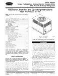
1
48TM016-028
Single-Package Rooftop Units
Electric Cooling/Gas Heating
Installation, Start-Up and Service Instructions
CONTENTS
Page
SAFETY CONSIDERATIONS ........................
1
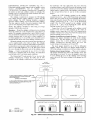
INSTALLATION ..................................
2-32
Step 1 -- Provide Unit Support .....................
2
• ROOF CURB
• ALTERNATE UNIT SUPPORT
Step 2 -- Rig and Place Unit .......................
2
• POSITIONING
• ROOF MOUNT
Step 3 -- Field Fabricate Ductwork ...............
11
Step 4 -- Make Unit Duct Connections
...........
11
Step 5 -- Install Flue Hood and Wind Baffle ...... 1;
Step 6 -- Trap Condensate Drain .................
11
Step 7 -- Orifice Change ..........................
12
Step 8- Install Gas Piping .......................
13
Step 9 -- Make Electrical Connections
...........
13
• FIELD POWER SUPPLY
• FIELD CONTROL WIRING
• OPTIONAL NON-FUSED DISCONNECT
• OPTIONAL CONVENIENCE OUTLET
Step 10- Make Outdoor-Air Inlet
Adjustments .....................................
16
• MANUAL OUTDOOR-AIR DAMPER
Step 11 -- Install Outdoor-Air Hood ..............
16
Step 12- Install All Accessories ...............
17
• MOTORMASTER® I CONTROL INSTALLATION
• MOTORMASTER V CONTROL INSTALLATION
Step 13- Adjust Factory-Installed Options ..... 19
• PREMIERLINK TM CONTROL
• ENTHALPY SWITCH/RECEIVER
• OUTDOOR ENTHALPY CONTROL
• DIFFERENTIAL ENTHALPY CONTROL
• OPTIONAL ECONOMISERIV AND ECONOMISER2
• ECONOMISERIV STANDARD SENSORS
• ECONOMISERIV CONTROL MODES
Step 14 -- Install Humidistat for
Optional MoistureMi$er TM Package ............
31
START-UP ....................................
33-43
SERVICE .....................................
43-50
TROUBLESHOOTING .........................
51-56
INDEX ...........................................
57
START-UP CHECKLIST ........................
CL-I
SAFETY
CONSIDERATIONS
Installation and servicing of air-conditioning equipment can
be hazardous due to system pressure and electric_d components. Only trained and qualified service personnel should install, repaik or service ai>conditioning equipment.
Manufacturer
Untrained personnel can perform basic maintenance functions of cleaning coils and filters and replacing filtel.s. All other
operations should be performed by trained service personnel.
When working on air-conditioning equipment, obselwe precautions in the literature, tags and labels attached to the unit, and
other safety precautions that may apply.
Follow all safety codes. Wear safety glasses and work
gloves. Use quenching cloth for unbrazing operations. Have
fire extinguishers available for _dl brazing operations.
Before performing service or maintenance
operations on
unit, turn off main power switch to unit. Electrical shock
could cause personal injury.
I.
2.
What to do if you smell gas:
1. DO NOT try to light any appliance.
2. DO NOT touch any electrical switch, or use any
phone in your building.
3. IMMEDIATELY call your gas supplier from a neighbor's phone. Follow the gas supplier's instructions.
4.
No. 04-53480016-01
Printed in U,S.A,
If you cannot reach your gas supplier,
department.
c_fll the fire
Disconnect gas piping from unit when pressure testing at
pressure greater than 0.5 psig. Pressures greater than
0.5 psig will cause gas valve damage resulting in haz_udous
condition. If gas valve is subjected to pressure greater than
0.5 psig, it must be replaced before use. When pressure
testing field-supplied gas piping at pressures of 0.5 psig or
less, a unit connected to such piping must be isohtted by
closing the manu_d gas valve(s).
limits are exceeded, the units will automatically
lock the
corupressor out of operation. Manual reset will be required
I IMPORTANT: Units have high ambient operating limits. If
to restart the compressor:
reserves the right to discontinue, or change at any time, specifications
Catalog
Improper installation, adjustment, alteration, service,
or maintenance can cause property &image, personal
injury, or loss of life. Refer to the User's Information
Manual provided with this unit for more details.
Do not store or use gasoline or other flammable
vapors and liquids in the vicinity of this or any other
appliance.
or designs without notice and without incurring obligations.
Form 48TM-4SI
Pg 1
3-06
Replaces:
48TM-3SI
I
I
INSTALLATION
Inspect unit for transportation damage. If &_mage is found,
file any claim with the transportation agency.
Step 1 --
Provide
Unit Support
ROOF CURB -- Assemble and install accessory roof curb or
horizont_d a&tpter roof curb in accordance with instructions
shipped with this accessory. See Fig. I-2B. Install insulation,
cant strips, roofing, and counter flashing as shown. Ductwork
can be installed to roof curb or horizontal adapter roof curb before unit is set in place. Curb or a&tpter roof curb should be
level. This is necessary to permit unit drain to function properly. Unit leveling tolerance is + l/ir_ in. per linear fl in any direction. Refer to Accessory Roof Curb or Horizontal A&_pter
Roof Curb Inst_fllation Instructions for additional information
as required. When accessory roof curb or horizontal adapter
roof curb is used, unit may be installed on class A, B, or C roof
covering material.
IMPORTANT: The gasketing of the unit to the roof curb
or adapter roof curb is critical for a watertight se_d.
Inst_fll gasket with the roof curb or adapter as shown in
Fig. 2A and 2B. Improperly applied gasket can also
result in air leaks and poor unit performance.
ALTERNATE UNIT SUPPORT -- When the curb or adapter
cannot be used, install unit on a noncombustible
surface. Support unit with sleepers, using unit curb support area. If sleepers
cannot be used, support long sides of unit with a minimum of
3 equally spaced 4-in. x 4-in. pads on each side.
Step 2 --
Rig and Place Unit--
Level by using unit frmne as a reference; leveling tolenmce is _+
_/lr_in. per linem fl in any direction. See Fig. 3 for additional information. Unit operating weight is shown in Table 1.
Four lifting holes are provided in ends of unit base rails as
shown in Fig. 3. Refer to rigging instructions on unit.
NOTE: On 48TM028 units, the lower forklift braces must
be removed prior to setting unit on roof curb.
POSITIONINGMaintain clearance, per Fig. 4-6, _u'ound
and above unit to provide minimum distance from combustible
materials, proper airflow, and service access.
Do not install unit in an indoor location. Do not locate unit
air inlets near exhaust vents or other sources of contmninated
all: For proper unit operation, adequate combustion and ventilation air must be provided in accordance with Section 5.3 (Air
for Combustion and Ventilation) of the National Fuel Gas
Code, ANSI Z223.1 (American National Standards Institute).
Although unit is weatherproof,
higher level runoff and overhangs.
guard against
water from
Ix)cate mechanical di'aft system flue assembly at least 4 il
from any opening through which combustion products could
enter the building, and at least 4 ft from any adjacent building.
When unit is located adjacent to public walkways, flue assembly must be at least 7 11 above grade. Ix)cate unit at least 10 1l
away from adjacent units.
ROOF MOUNT -bution requirements.
Table 1.
Check building codes for weight distriUnit operating weight is shown in
hlstructions
continued
on page ll.
Do not drop unit;
keep upright. Use spreader bars over unit to prevent sling or cable &image. Rollers may be used to move unit across a roof.
25% VENTAIR//
ECONOMIZER
HOOD
LOC -O P
I
I
I
///
HORIZONTAL
SUPPLY
CURB (CRRFCURB013A00)
7
TRANSITION
FULLYINSULATED
SUPPLYPLENUM
14-314 _
32_]
,
_
_
!t]//
143/4"/
2"uXI_)RTTYP.
II
11"11/NSUDL_TIsINy,
STI,IK PINN?D & _UED
Z
I
/
23"
12" WIDE STANDING
SEAM PANELS
ACCESSORY
CURB
PACKAGE NO.
HEIGHT.
CRRFCURB013A00]
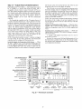
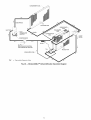
Fig. 1 -- Horizontal Supply/Return
/_
STITCH WELDED/
NOTE: CRRFCURB013A00
is a fully factory preassembled horizontal adapter and includes an insulated transition duct. The pressure drop through the adapter curb is negligible.
For horizontal return applications: The power exhaust and barometric relief dampers must be installed in the return air duct.
DUCT
(584)
DESCRIPTION
]
Pre-Assembled, Roof Curb,
Horizontal Adapter
Adapter Installation (48TM016-025)
NOTES_
1
BOBff CLJRB ACCBB (}BY /
Bi
PPLD O[ AS7 v:q F';.
2.
]NBUtA[ED
PANFL5_
I"
THICK
N_OPREkE
CBArLn
3
D]MFNSi0NS
IN
( ) AR _ iN Mil
]_ETEI_S_
4_ _:_:s_ DIRECT _0N OR A[i/
FI OW
i¸¸//2
'..,4
O'
3/4"
/
(44J
/
/
/
/
NON.
/4"
X 4"
(32)
X (102)
IYP,
4 Pl C5
O"
] SUL/>YEO PANEL O7i
]DE
SUPPL Y AND RETURN
(CRRFCUR_B]
2AO0
ONLY}
i/4
_
FI
I
(44)
5'
? i/[6
(i703_
=
Fig. 2A
i
Roof Curb Details
i
48TM016-025
{) SUI>L
DUCI
D
.....
,CAN/
SR]I
>
SUP>L [ED)
LB
[}ENB[TY
ROOFCURB
CURB
A CESSOR,
NE,O.,
OESC I.ION
RR'CUROO
.SO,,,.AO0
H,OH
....
6
D 1/4"
'-I
DI'_END[ONS
(DECREES AND INCHES)
"
A
B
UNIT
DE6.
IN.
DEG.
IN.
ALL
.28
.45
.28
.43
MAX
FROM
CURB
EDGE
LEVELING
OF
UNIT
TOLERANCES:
TO
HORIZONTAL
_---COMPREBSOR AD
CO DENSER ENC
/ is/)6 t
i//0_
i122621
INSULA"_D
I
UPPLY
OPEN'NG
PANEl
CURB
1
7 17!16 '1
J
(584)
COR{)FNSATR BRAi_
I
_3/'D
1
B]
I
?
(CAS KEEP
ENTRYTHIS
FOR ANEA
6AS CLEAR
F_REB
4_
FOR
POWER_I_
ROOPTOPS/
"i
NOTES:
I+ R_FCURB ACCESSORY IS SHIPPED DISASSEMBLED.
2. DIXENSlOUS IN (I ARE IN WILLIWETERS.
3. [222_DIRECTION
OF AIRFLOW.
(/321
NAIL
4. ROOF CURB: IG OA. )VA03-56} STEEL.
5. TO PREVENT TXE HAZARD OF STAONANT WATER BUILD-UP IN THE DRAIN PAN
OF fNZ INDOOR SECTION. UNIT CAN ONLY BE PITCHED AS SXOWU.
6. INSULATED PANELS: I" THICK NEOPRENE COATED 1-I12 LB DENSITY.
(SUPPLIED
6ASEET
WITH CURB)
.COUNTER
(FIELD
FLASHING
SUPPLIEOi
ROOFING
FELT
/(FIZLD
SUPPLIED}
FIELD SUPPLIED
_-CANT
(FIELD
STRIP
SUPPLIEOi
ROOFING
MATERIAL
/(FIELD
i
i14'
/32)
HEIGHT FRO_ TABLE
(2262)_
NOM
5/4"
_
X 41'
(iBB6/
TYP _ PLACES
Fig. 2B -- Roof Curb Details -- 48TM028
SUPPLIED)
"DETAIL A"
SPR D
RIGGING HOOK
3'-7 1/2"
UNIT BASE RAIL
NOTES:
1. Dimensions in ( ) are in millimeters.
2. Refer to Fig. 4-6 for unit operating weights.
3. Remove boards at ends of unit and runners prior to rigging.
4. Rig by inserting hooks into unit base rails as shown. Use corner post from packaging to protect coil from
damage. Use bumper boards for spreader bars on all units.
5. Weights do not include optional economizer. Add 90 Ib (41 kg) for economizer weight.
6. Weights given are for aluminum evaporator and condenser coil plate fins.
All panels must be in place when rigging.
UNIT
48TM
016
020
025
028
DIMENSIONS
MAXIMUM
SHIPPING WEIGHT
Ib
1875
1925
kg
850
873
2035
2445
923
1109
A
B
ft-in,
mm
ft-in,
mm
6-111_
2121
4-0
1219
6-111_
2121
3-2
964
6-111_
2121
3-4
1016
6-111_
2121
3-4
1016
Fig. 3 -- Rigging Details
........
CO'_UERO
(99)
O"
_.
i _
_
/_._
20t
Z/_'DA
7
[
3/15"
:_i"
(04
4 5/
!
!
(4
X+AI_HO
@fi_i"
r
4 /
[
@_
4_])
[
/_
...........
,
l
i
i
[
......
////_
_
11
1]
/_'_',",
_\
j
i
Z
"---
,
....
k
_
l
_llk'lx/_i]/X
'
................
S
,
6>0"
I
j
z
7
/s/SC'S
3 15/
+
O(
/
-
l
;j._
I _ _ - - --
/,
'-
_i ;+
sS
v
.....................................
@"
'
O"
'
[
5
15/5"
i
(1)
....
J
....
-+_ i -°,o
b
8i1
,"
SU
})0_
4 ,/1[ 09
l
s:
o_
i
j
j
j
l
l
:
l
[
J _............/_.._'_
/,,I
•
/1_*
(1707
i[
.....
0[_3_
_
.........
_
',"_"
i
_
VO\/i
_-_
_iKJ N
J
+
I
;
l
J
J
i
J
J
?I
"
l
l
1 ./s
°
! !
J
hO[
+m _2,
, ii |
AL
x
'_
825
!
Oi_S
:i
_
i
I
'
"
i
j
_'_i
_
(21
\
/_+
/
'
H_lq
7)
4
COR\ER5
J
I
:
j
I
:
J
I
2"
2
1,
B+i
(i)
\
j
5
8
<@ [228
K
(61)
(070)
i5 )
-j
i
_
O!
A
/N
D R
+
OR
J
s,
1_
1-0 E_S)RY
RE 0
F OPO
(
OxY
T 05
3'0
DiMNS]ONS
#i/
ALL)W 0
5/_"
(
0
(JR[
TIIS
]
+
9/45
0
_
0
O\[Y.
D
PER"
E-]Oq
T 0
(R
i0
LOK
B£
R
CO.
UN[
[
0
NAY P_EVA[
AIR
[+Od.
.
0> RA] ]0
(J
iPP
CO O.
DE!OER
SN
VR AOI5
WEN
TO U
CA
L EMOW_L
OU_ ;:,s
!N
[OR PR(P[_
(00[NI
(0
]RO
lOX
'_OC[{J
J} _
4"0"
I/ _)
Oz_ P (P
AO _ POWER
T
50
EQ
8"0
(1829 EX"*M
TO ASOL,R
PROPER
:
14 + (3)
TO DOt'SJ
+:1[
EX EPI]ON
OAMPER/>OdER
_ NC
OR
RO0
AL.
s: U,_AC.,
g}
D
][):
)]M:Ns
ZIPS.
)s
COL
21g
r coM,
W TM
_B
TE
[<[O'AB!
j
I
i)
4'0 +
19}
0
r
AItD
1:
54)
• [ [
mJ_](NJ;
[} :
/;'0"
"
• O)KTRO[
OX
]D:
i'6"
Oil
R GROUN) [ SLRIA
}S.
• iO(A
(0
b OR JJR S} C]
"_"
/
;_x_
"
ROOF: CURB ACC:,
S[_Z
RECI]O
"00N
_'OINoF
)MiLE,OX
J
:
:OR
(
° '°"
,w h
• lOT
CAL
/N
_
• RIOHJ
DAMP
"TOP:
/
TYP
TO PRINT
_SIONS
REDU EO TO+o.
,+o_
4"0"
/
I
}:
i
_EF R
)In
.
D{UI_(RK
0 [l
. .R_R:
]N[
Uq 7"0 [£ARA
+ (2
+-
L
I?_3
1
t
O0
"h
J .
ii)
'_/.....
18i K
"
?
"
l
K
;_(g
d
'
i IU
....................
....................
....................
_'J
Y
_
41 <
I O_
j
.
.is
_G
_
"
OPER,STIOP.
\0
[;1\6
5URFA
CUR)
ES,
COCR
[{ WA[
,
R
.
O
LEA /-!1 E OR
IME
ONDE/',
R tOiL
EX AUST _
SATED
k fOE
# +
/q_(IC_,D
RGJRE5
sO Cl AW41
_
FI/O_
!IOE
#OH
CORN
FO_
[
_ >_
0 ) COVER
[R[
) E DE,
0'2"($/)
S
/
I(i2F)
k_O'-ll
(303)
"
OORNI!R
_ (?÷}
5/I[5"
(339)
j
O"
5 _/
6"
i
_e
z
]
,%,
_[_@
"
'NO_CR
"
/4
kz_
;;/i
:?
_R
/
's
OO]L
i IA
_I
\ tOq
ON
:
Y
,,,,
lv.,
,,
(466)
+,:DwZ Z
B_ROHETR
i
C
RFLTEF/>OWER
C
"
y
EIsS } "
N(
_!
FX
-
AUST
_}÷A+\
o" <so_°/4_
', ' o ." o
_
bz)
+
J
o
(7
:,,+.
(4s_:l
o
A_
.................................................................................................................................................
[
.
c+,Y _
"/O//_
718 O]# CONO[INiRiO
K,O.
_ (22)
(FIELD
?OWER)
15/16"_
i'
[
(Z_)
; .....
(_(_
_Ju
(73}
_.
\
I
_
O"''''_ _ \
.
3
.,, ,
,
,
O A K.O,
'"
(OONT:£OL)
......
=
I
(,
+. _M oPo,_>
_7/;'
_ ........................................................"
Fig. 4 -- Base Unit Dimensions J 48TM016,020
i
_
_o_,,"
:::: s :::h, _........................
l
\, ,,,'o,,O,E
_
.to,
L_N
/
_/
6
........................................................
4
t
_)
*
.t
FCORNERA
CORNER8
TYP
O'-3
(4)
PLC5
7/B"
{££}
7!
(206)
I
]......
I......
I_ IolcIol
UNIf
5TD. UNIT ECON_EZER
CORNER
CORNER
CORNER
CORNER
DIM A
I I I
OlM B
DIM C
ro._s18,io,
t .....
,T,o
.....
i,,
L....
oI....
].....
I.....
I_;#_i]......
I.....
I
......
,oLD...................
3._7-,._o-
I
0"-4
5/16
I_
"
|
I J]_
,50
81A
-|
I ]
HOLE_
2 " DO
2.
OIMENSION5
IN {)FOR ARE
MILLIMETERS.
NOT_'REFER
TO PRINT
ROOFIN CUR3
ACCESSORY
3,
_
CENTER OF GRAVITY,
4.
_
DIRECTION
OF AIR FLOW.
DIMENSIONS.
3
|l_
/1
TYPICAL
/
X_
_.)
_.
_
S'-11
7/8
(13275_.1[ .
5"-7
3/16"
(1707)
BECTIOI
-
--
(1753)
TYPICAL
I
I
....
z -z
'
[,_._x_]
)_
I
4"3 _ (1213)
TO COMBUSTIBLE
FRoMREDUCED
REMOVALTHE
TO
TOP,
4"0"
(1213)
IF
BETWEEN
UN
T5
ALL FOUR SIDES
PERMIT
COIL
TOP_
G'O"
(1823)
3OTTOM_
14"
(356)
7.
POWER EXHAUST
(ACCESSORY
ONLY)
SURFACES,
CONSITIONS
COIL
OF
CAN BE
(INCLUDES
AIR
FLOW.
8_
TO ASSURE PROPER CONDENSER FAN OPERATION,
TO COMBUSTIBLE
SURFACES
(WHEN NOT USING
NON-COMBUSTIBLE,
CONTROL
3'6"
(057)
TO UNGROUNDED
BLOCK OR CONCRETE
CONTROL 30X
30X SIDE:
51DE!
3"0"
(314)
TO
SURFACES, WALL5_
OTHER
GROUNDED SURFACES,
LOCAL CODES OR JURISOtCTION
MAY PREVAIL.
WITH THE EXCEPTION
OF CLEARANCE
FOR THE CONDENSER COIL
AND THE DAMPER/POWER
EXHAUST
AS 5TATEO
IN NOTE #6,
A
81MENSIONS
ARE FROM OUTSI3E
OF CORNER POST,
ALLOW 0'-5/16"
(B)
ON EACH SIDE
FOR TOP COVER DRIP
CURB),
OR
EOOE,
2
3/15"
O'-lO
ROOF
CURB ONLY.
THIS
DIMENSION
OAMPERANOPOWEREX.AUS
4 CORNERS
I
I
_
DUCTWORK CLEARANCE:
MINIMUM
TO BE ATTACHED
TO ACCESSORY
REAR:
7'0"
(2134)
FOR COIL REMOVAL.
FRONT:
4"0"
(1219)
FOR CONTROL
BOX ACCESS,
LEFT SIDE:
4"0"
(1219)
FOR PROPER
R]GHT
SLOE:
4'3"
(1213)FOR
PROPER CONDENSER
OPERATION
(2187)
7"-2
1/8"
I_1
I
I
6.
S,
TYPICAL
1/4"
D A HOLE
_11 l/_yp
_
<yis.B ;i
/
}
_2.3
--4
OUTDOOR
2_
COIL
/
C8RNER
C
_
(76)
D_2
3/8 _
DIA
K_O_
(Sl)
CONCENTRIC
K_O_
(3S_
1/4 _
($7)
I
DIA
H
u
TO_
_
!........!
3'-11
%_;;L._o,,,o-_-
1/4"
(466)
t
(1200)
> ....
--------
--.
VIEW
BAROMETRIC
Z-Z
RELIEF/POWER
(ACCESSORY
EXHAUST
ONLY)
\
\
TYP
//
\\
._
_ _
\"\_s,8-_,
_,3-O,ACONCENTR,C_O(B_)
_(_S)
(F,ELD
POWER) /--_O'-_FI
O'-lO(260) 1/4"/_L_
(457)
/
0'-2
o_
_i
_;°'
{73)
0"-2
(51)
COIL
3/4"
(27)
FPT
FAR
DRAIN
SlOE
(102)
ALTERNATE
CONNECTION
ONLY
0'-3
RETURN
71B_
(SB)
l'-3/1G_
(310}
0'-2
liB'
(54)
,,_.DIA
,.o.{GAS
ENTRY)
_,0"
NPT]\ 3/
\_7,BOIAK.O.
(CONTROL)__
(_8)_,_
8IANOLE
_
\1
0/0_)
"I
"
(22)
"-
(SB)
Fig. 5 -- Base Unit Dimensions i
5"-6"
(1676)
48TM025
5ECTION
A-A
"
-
O'-B
15/16"
_"I_
Z'U2"
O0
4 T
2270 L8
90 LB
532 LB
526 LB
569 LB
593 L8
4*-6"
-7
I/4"
'-I
I/4
I'-7
(504)
i
k.__.
i
j_
NOTES
48TH028
1, :REFER
TO PRINT
2, DIMENSIONB
IN
FOR ROOF CURB
ACCESBORY
( ) ARE IN MILLIMETERS.
DIMENSIONS,
,\,SOBIA
DLE
3. CENTENOFBOAV,TY.
--..q
__L. ...... s.O00TNOR<
TO
OE
ATTAC.EO
TO
A=SSOOY
ROOF
CUBO
ONLY.
4.
TYPICAL
•
TYPICAL
"'fYPTCAL
.....
6.
4 CORNERS
0"-3"
0i2o2)
7'-2
1/8"
(2187)
SECTION
A-A
7.
LY
B.
Do
0"-4"_
(102)
DIA
(127)
HOLE
(22)
0'-2_
(303)
'-II
B*
ACCESS
(567)
AIR
r_1,1o
DIRECTION
OF
AIR
FLOW,
YO
813)
(51)
0"-3
_
MINIMUM
CLEARANCE:
REAR:
7'0"
(2134)
FOR COIL REMOVAL.
THiS
DIMENSION
CAN BE
REDUCED TO 4"0*
(1219)
IF CONDITIONS
PERMIT
COIL REMOVAL
FROM THE TOP.
4'0"
(1219)
TO COMBUSTIBLE
SURFACES,
ALL FOUR BIDES
(INCLUDES
BETWEEN UNITS.
LEFT
510E_
4"0*
(1219)
FOR PROPER CONDEN5ER COIL
AIR FLOW.
FRONT:
4"0"
(1219)
FOR CONTROL BOX ACCESS.
RIGHT
SIDE=
4"0"
(1219)
FOR PROPER OPERATION
OF
DAMPER AND POWER EXHAUST
IF SO EOUIPPED.
TOP:
S'O*
(1829)
TO ASSURE PROPER CONDENSER FAN OPERATION.
8OTTO\:
14"
(355)
TO COMBUSTIBLE
SURFACES
(WHEN NOT USING CURB).
CONTROL BOX SLOE!
3"0"
(914)
TO UNGROUNDED SURFACE5,
NON-COMBUSTIBLE.
CONTROL BOX SIDE_
3"6*
(1067)
TO BLOCK OR CONCRETE WALLS,
OR
OTHER GROUNDED SURFACES.
LOCAL CODES OR JURISDICTION
MAY PREVAIL.
WITH THE EXCEPTION
OF CLEARANCE
FOR THE CONDEN5ER COIL
AND THE DAMPER/POWER
EXHAUST
AS STATED
IN NOTE _6,
A
REMOVABLE
FENCE OR BARRICADE
REOUIRE5
NO CLEARANCE.
DIMENSIONS
ARE FROM OUTSIDE
OF CORNER POST.
ALLOW 0'-5/16"
(8)
ON EACH 51DE FOR TOP COVER DRIP EDGE.
ECONOMIZER
2'-1
OPENING
"-
,
.
•
OR (79)
HOOD
1'-1
"
1/8 *_
5115"
,
(339)
,._s(2#;
i
_-
0"-3
(87)
7/16"
_
FO'
-3'
c467)
(lO2)
(99)
TYP
3/4"
(4)
0"-2"
(51)
TYP
(27)
FPT
DRAIN
FAR
51DE
-ALTERNATE
CONNECTION
ONLY
Fig. 6
i
O'-IO
l 14" _--_
(260)
0"-2
7/B _
(73)
0"-3
7/B_
RETURN
(98)
1'-3/15%
(310)
0"-2
ltB
(54)
X
_718921_1
_1
-
B,O"
<,3,B"
O,A
CONCENTR,C
<.O.
p
# K!3O_)
1,2172DIA
(38)
((EFoINFTLRDoL
pOWER)
(GAS
ENTRY)
5" -6"
(1576)
"_j
Base Unit Dimensions i
K.O+
48TM028
314"
0;53"
NPT
/
J
"1(31/4
DIA
HOLE
ONLY)
<ACC[_O_Y
_
Jl
_
(75)
j_
8_[_
5/8"
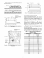
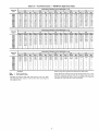
Table1--
Physical Data
UNIT 48TM
NOMINAL CAPACITY (tons)
OPERATING WEIGHT
Economizer
MoistureMi$er TM Dehumidification
COMPRESSOR/MANUFACTU
Quantity...Model
Package
028D/F
20
1900
90
40
25
2270
90
40
1...ZB94KC,
1...ZR72KC
2
60, 40
85, 60
I
13-8
2
55, 45
108, 81
Rows...Finslin.
Total Face Area (sq ft)
4._15
21.7
I
10,500
1/2...1050
(in.)
3...22
1100
COIL
I
I
4...15
21.7
2
55, 45
108,106
R-22
TXV
4...15
17.5
2
50, 50
138, 106
19-11I
13-14
Motor Bearing Type
Maximum Allowable Rpm
Motor Pulley Pitch Diameter
MiniMax (in.)
Nominal Motor Shaft Diameter (in.)
Fan Pulley Pitch Diameter (in.)
Nominal Fan Shaft Diameter (in.)
Belt, Quantity...Type...Length
(in.)
Pulley Center Line Distance (in.)
Speed Change per Full Turn of
Movable Pulley Flange (rpm)
Movable Pulley Maximum Full Turns
From Closed Position
Factory Speed
Factory Speed Setting (rpm)
Low-Medium
High Static
Static
Low-Medium
High Static
Static
Low-Medium
High Static
Static
Low-Medium
High Static
Static
Low-Medium
High Static
Static
3...22
1100
28-13
25-10
4...15
17.5
873-1021
1025-1200
Ball
1550
4.9/5.9
4.9/5.9
11/8
9.4
8.0
17/1G
910-1095
1069-1287
1002-1151
1193-1369
Ball
1550
4.9/5.9
4.9/5.9
11/8
9.4
8.0
17/16
1...BX...50
1...BX...48
13.3-14.8
37
44
1...BX...50
1...BX...48
13.3-14.8
37
34
Ball
1550
5.4/6.6
5.4/6.6
13/8
9.4
7.9
17/le
1 ...BX...53
1 ...BX...5O
14.6-15.4
37
44
2...12 x 12
Belt
7200
5
1745
8tt
3.5
1002
1178
17/16
LEGEND
Brake Horsepower
Thermostatic Expansion Valve
*The ZRU140KC compressor is a tandem compressor, consisting of a ZR72KC (25% total
capacity) and a ZR68KC (24% total capacity).
1-Circuit 1 uses the lower portion of the condenser coil and lower portion of the evaporator
coils; and Circuit 2 uses the upper portion of both coils.
**Pulley has 6 turns. Due to belt and pulley size, movable pulley cannot be set to 0 to 11/2
turns open.
1-1-Pulleyhas 6 turns. Due to belt and pulley size, movable pulley cannot be set to 0 to 1/2turns
open.
***Rollout switch is manual reset.
1-tl-A Liquid Propane kit is available as an accessory.
'liThe 48TM028 unit requires 2-in. industrial-grade filters capable of handling face velocities up
to 625 ft/min (such as American Air Filter no. 5700 or equivalent).
units have a low-pressure
4...15
17.5
5.90
Fan Shaft Diameter at Pulley (in.)
NOTE: The 48TM016-028
side.
I
184T
Static
switch (standard)
3...15(2ceils)
43.4
21,000
1/2...1050
6...22
2200
3/8-in. Copper Tubes, Aluminum Lanced or
Copper Plate Fins, Face Split
6.13
3.5
965
1134
17/1G
I
1...1075
2...30
3400
1/2...1050
184T
6"*
Low-Medium
High Static
4...15
21.7
Propeller Type
14,200
Centrifugal Type
2...12 x 12
Belt
8000
7.5
1745
8.7 [208/230, 575 v]
9.5 [460 v]
213T
2...12 x 12
Belt
6000
5
1745
Maximum Continuous Bhp
Motor Frame Size
Nominal Rpm High/Low
Fan Rpm Range
I
I
10,500
Cross-Hatched
Rows...Fins/in.
Total Face Area (sq ft)
EVAPORATOR FAN
Quantity...Size (in.)
Type Drive
Nominal Cfm
Motor Hp
Motor Nominal Rpm
---
1 ...ZRU140KC,*
1...ZR144KC
Cross-Hatched 3/8-in. Copper Tubes, Aluminum Lanced,
Aluminum Pre-Coated, or Copper Plate Fins
CONDENSER FAN
Nominal Cfm
Bhp
TXV
11...ZR108KC
...ZB125KC,
19-2
COIL
Motor Hp...Rpm
Quantity...Diameter
Watts
Input (Total)
I 11...ZR94KC
...ZR108KC,
198I 198I
2
EVAPORATOR
025D/F
18
1850
90
40
Scroll, Copeland
(Ckt 1, Ckt 2)
c,rcu,t,,
CONDENSER
020D/F
15
1800
90
40
RER
Number of Refrigerant Circuits
Capacity Stages (%)
Oil (oz) (Ckt 1, Ckt 2)
REFRIGERANT TYPE
Expansion Device
Operating Charge (Ib-oz)
Circuit
016D/F
located on the suction
6 _*
3.5
1120
1328
17/le
I
4...15
17.5
2...12 x 12
Belt
10,000
10
1740
10.2 [208/230, 575 v]
11.8 [480 v]
215T
1066-1283
1332-1550
Ball
1550
4.9/5.9
4.9/5.9
13/8
8.0
6.4
17/16
2...BX...5O
2...BX...47
14.6-15.4
36
45
61-13.5
1182
1470
17116
Table 1 -- Physical Data (cont)
UNIT 48TM
FURNACE SECTION
Rollout Switch Cutout Temp (F)***
Burner Orifice Diameter (in....drill size)
Natural Gas
Std
Thermostat Heat Anticipator Setting (amps)
2081230, 575 v
Stage 1
Stage 2
460 v
Stage 1
Stage 2
Gas Input
Stage 1
Stage 2
Efficiency (Steady-State) (%)
Temperature Rise Range
Manifold Pressure (in. wg)
Natural Gas
Std
Liquid Propanettt
AIt
Gas Valve Quantity
Gas Valve Pressure Range
in. wg
psig
Field Gas Connection Size (in.-FPT)
HIGH-PRESSURE
Cutout
Reset (Auto)
SWITCH (psig)
LOW=PRESSURE
Cutout
Reset (Auto)
SWITCH (psig)
016D/F
020D/F
025D/F
028D/F
19o
19o
19o
190
0.1285...30/0.136...29
0.1285._30/0.136...29
0.98
0.44
0.80
0.44
172,000/225,000
230,000/300,000
81
18-45/20-80
0.1285...30/0.136...29
0.98
0.44
0.80
0.44
206,000/270,000
275,000/360,000
81
18-48/20-50
0.98
0.44
0.80
0.44
206,000/270,000
275,000/360,000
81
15-45/20-50
3.3
3.3
1
3.3
3.3
1
3.3
3.3
1
5.5-13.5
0.235-0.487
3/4
5.5-13.5
0.235-0.487
5.5-13.5
0.235-0.487
3/4
3.3
3.3
1
3/4
5.5-13.5
0.235-0.487
3/4
27
44
THERMOSTAT
(F)
30 _+5
45 _+5
OUTDOOR-AIR INLET SCREENS
Quantity...Size (in.)
Cleanable
2...20 x 25 x 1
1...20 x 20 x 1
RETURN-AIR
FILTERS
Quantity...Size
(in.)
Throwawayl]
4...20 x 20 x 2
4...16 x20 x 2
EXHAUST
1/2 Hp, 208/230-460
v Motor
Direct
Drive,
LEGEND
Bhp -TXV --
0.98
0.44
0.80
0.44
206,000/270,000
275,000/360,000
81
15-45_0-50
426
320
FREEZE PROTECTION
Opens
Closes
POWER
0.1285...30/0.136...29
Brake Horsepower
Thermostatic Expansion Valve
*The ZRU140KC compressor is a tandem compressor, consisting of a ZR72KC (25% total
capacity) and a ZR68KC (24% total capacity).
1-Circuit 1 uses the lower portion of the condenser coil and lower portion of the evaporator
coils; and Circuit 2 uses the upper portion of both coils.
**Pulley has 6 turns. Due to belt and pulley size, movable pulley cannot be set to 0 to 11/2
turns open.
1-1-Pulleyhas 6 turns. Due to belt and pulley size, movable pulley cannot be set to 0 to 1/2 turns
open.
***Rollout switch is manual reset.
1-1-1-ALiquid Propane kit is available as an accessory.
'liThe 48TM028 unit requires 2-in. industrial-grade filters capable of handling face velocities up
to 625 ft/min (such as American Air Filter no. 5700 or equivalent).
NOTE: The 48TM016-028 units have a low-pressure switch (standard) located on the suction
side.
]0
Propeller-Fan
(Factory-Wired
for 460 v)
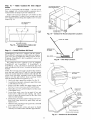
Step 3 --
Field Fabricate Ductwork -- Secure all
ducts to building structure. Use flexible duct connectors between unit and ducts as required. Insulate and weatherproof all
external ductwork, joints, and roof openings with counter
flashing and mastic in accordance with applicable codes.
Ducts passing through an unconditioned
sulated and covered with a vapor barriel:
Step 4 --
Step 5 --
Install
Flue Hood and Wind
space must be in-
Step 6 -- Trap Condensate
Make Unit Duct Connections
--
Baffle --
Flue hood and wind baffle are shipped secured under main
control box. To install, secure flue hood to access panel. See
Fig. 10. The wind baffle is then installed over the flue hood.
NOTE: When properly installed, flue hood will line up with
combustion fan housing. See Fig. 11.
Unit
Drain -- See Fig. 12
for drain location. One 3/4-in. half coupling is provided inside
unit evaporator section for condensate drain connection. An
81/2-in. x 3/4-in. diameter and 2-in. x 3/4-in. diameter pipe nipple, coupled to standard 3/4-in. diameter elbows, provide a
straight path down through hole in unit base rails (see Fig. 13).
A trap at least 4-in. deep must be used.
is shipped for thru-the-bottonl duct connections. Ductwork
openings tue shown in Fig. 1 and 4-6. Duct connections are
shown in Fig. 7. Field-fabricated
concentric ductwork may be
connected as shown in Fig. 8 and 9. Attach all ductwork to roof
curb and roof cm#, basepans.
HEAT
SEE NOTE
BAF/FLE
[_AIR
NOTE: Dimensions A, A', B, and B' are obtained from field-supplied
ceiling diffuser.
Shaded area indicates block-off panels.
OUT
NOTE: Do not drill in this area; damage to basepan may result in
water leak.
Fig. 7 -- Air
Distribution
Fig. 9 --
Concentric
Duct
Details
-- Thru-the-Bottom
/
/
\
/
\
r
I
\
/-...
\
/
\
/
WIND
BAFFLE
_HEAT
EXCHANGER
FLUE
HOOD
\
\
/
NOTE
\
X
\
\
\
\
/
\
\
\\
\\
COMBUSTION
FAN HOUSING
(INSIDE)
/
/
\
\\\
%
_SEENOTE
/
\
\
/
/
\
I
WIND BAFFLE
MOUNTING HOLES
AIR OUT
AIR IN
AIR OUT
m
NOTE: Do not drill in this area; damage to basepan may result in
water leak.
Fig. 8 -- Concentric
i
Fig. 10--
Duct Air Distribution
11
Flue Hood Location
INDUCED
MOTOR
Step 7 -- Orifice Change -- This unit is factory assembled for heating operation using natural gas at an elevation
DRAFT
from sea level to 2000 ft. This unit uses orifice type
LH32RFnnn, where "nnn" indicates the orifice size based on
drill size diameter in thousands of an inch.
HIGH ELEVATION (Above 2000 ft) -- Use accessory high
altitude kit when inst_dling this unit at an elewttion of 2000 to
7000 ft. For elevations above 7000 ft, refer to Table 2 to identify the correct orifice size for the elevation. See Table 3 for the
number of orifices requiled for each unit size. Purchase these
orifices from your local Carrier dealel: Follow instructions in
accessory Installation Instructions to install the correct orifices.
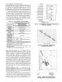
Table
Compensation*
2 -- Altitude
ELEVATION (ft)
NATURAL
Low
COMBUSTION
FAN HOUSING
MAIN BURNER
SECTION
Fig. 11 -- Combustion
0-1,999
2,000
3,000
4,000
5,000
6,000
7,000
8,000
9,000
10,000
HEAT EXCHANGER
SECTION
Fan Housing Location
GAS ORIFICEt
Heat
30
30
31
31
31
31
32
32
33
35
High
Heat
29
29
30
30
30
30
31
31
31
32
*As the height above sea level increases, there is less oxygen per
cubic foot of air. Therefore, heat input rate should be reduced at
higher altitudes. Includes a 4% input reduction per each 1000 ft.
1-Orifices available through your Carrier dealer.
Table 3 -- Orifice Quantity
\
\
UNIT
\
\
\
\
\
\
\\\
\
ORIFICE QUANTITY
48TMD016
5
48TMD020,
48TMD024,
48TMD028,
48TMF016
6
48TMF020,
48TMF024,
48TMF028
7
\\\
&
\
\
\
\
CONVERSION
TO LP (Liquid Propane) GAS -- Use accessory LP gas conversion kit when converting this unit for use
with LP fuel usage for elevations up to 7000 ft. For elevations
above 7000 ft, refer to Table 4 to identify the conect orifice
size for the elewttion. See Table 3 for the number of orifices
required for each unit size. Purchase these orifices from your
loc_d Carrier dealel: Follow instructions in accessory Installation Instructions to inst_dl the correct orifices.
\
\\
3/4" FPT DRAIN
CONNECTION
Fig. 12-
3/4"
1-3/8"
DRAIN HOLE
Condensate Drain Details
(48TM016 Shown)
Table 4 -- LP Gas Conversion*
ELEVATION (ft)
0-1,999
2,000
3,000
4,000
5,000
6,000
7,000
8,000
9,000
10,000
FPT
2-1N. (FIELD-SUPPLIED)
cC°
NIPPLE
3 _
/.
8 1/2-1N. (FIELD- _-w
SUPPLIED) NIPPLE
Condensate
36
37
38
38
39
40
41
41
42
43
*As the height above sea level increases, there is less oxygen per
cubic foot of air. Therefore, heat input rate should be reduced at
higher altitudes. Includes a 4% input reduction per each 1000 ft.
1-Orifices available through your Carrier dealer.
BASE RAIL _-_1
Fig. 13-
LP GAS ORIFICE1-
Drain Piping Details
12
Step 8 --
Install Gas Piping -- Unit is equipped for
use with natmM gas. Installation must conform with loc_d
building codes or. in the absence of loc_d codes, with the
National Fuel Gas Code, ANSI Z223.1.
Field wiring must confirm to temperature limitations for
type "T" wire. All field wiring must comply with NEC and local requirements.
Transformer no. 1 is wired for 230-v unit. If 208/230-v unit
is to be mn with 208-v power supply, the transformer must be
rewired as follows:
Install field-supplied manual gas shutoff valve with a l/s-in.
NPT plessure mp for test gage connection at unit. Field gas
piping must include sediment trap and union. See Fig. 14.
1. Remove
Do not pressure test gas supply while connected to unit.
Always disconnect union before servicing. Exceeding
maximum manifold pressure may cause explosion and
injury.
cap from red (208 v) wire.
2.
Remove cap from orange (230 v) spliced wire.
3.
Replace orange wire with led wire.
4.
Recap both wires.
Be certain unused wires are capped. Failure to do so may
&Lmagethe transformers.
I
tion must not be less than 5.5 in. wg or greater than
IMPORTANT:
Natural gas pressure at unit gas connec13.5 in. wg.
Operating voltage to compressor
must be within voltage
range indicated on unit nameplate. On 3-phase units, voltages
between phases must be balanced within 2%.
Size gas-supply piping for 0.5-in. wg maximum pressure
drop. Do not use supply pipe sm_dler than unit gas connection.
Unit failure as a result of operation on improper line voltage
or excessive phase imbalance constitutes abuse and may cause
&_mage to electrical components.
MANUAL SHUTOFF
(FIELD SUP_
FIELD CONTROL WIRING -- Install a Carrier-approved
accessory thermostat assembly according to inst_dlafion instructions included with accessory. Ix)cate thermostat assembly
on a solid interior wall in the conditioned space to sense average temperature.
GAS
(118" NPT PLUG)
Route thermostat
cable or equivalent
single leads of
colored wire from subbase termimds through conduit in unit to
low-voltage connections as shown on unit label wiring diagram
and in Fig. 16.
UNIT
UNICORN
_
Fig. 14--
NOTE: For wire runs up to 50 ft, use no. 18 AWG (Americ_m
Wire Gage) insulated wire (35 C minimum). For 50 to 75 fl,
use no. 16 AWG insulated wire (35 C minimum). For over
75 ft, use no. 14 AWG insulated wire (35 C minimum). All
wire larger than no. 18 AWG cannot be directly connected at
the thermostat and will require a junction box and splice at the
thermostat.
"l-"-"_ S EDIME NT TRAP
Field Gas Piping
Set heat anticipator settings as follows:
Step 9 --
Make Electrical
Connections
FIELD POWER SUPPLYUnit is factory wiled for voltage shown on nameplate.
When installing units, provide a disconnect
per NEC
(National Electrical Code) of adequate size (Table 5).
All field
requirements.
wiring
must
comply
with
NEC
and
VO LTAG E
W1
W2
208/230,575
460
0.98
0.80
0.44
0.44
Settings may be changed slightly to provide a greater degree
of comfort for a particul_u installation.
local
Route power ground lines through control box end panel or
unit basepan (see Fig. 4-6) to connections as shown on unit
wiring diagram and Fig. 15.
....
I
TBI
FIELD
II
_II
II
I
fill
|
_
r-L-q
I r-_
r-_
II_
POWER
z_
The correct power phasing is critical in the operation of the
scroll compressols. An incorrect phasing will cause the
compressor to rotate in the wrong direction. This may lead
to premature compressor failure.
l
SUPPLY
EQUIP
The unit must be electrically grounded in accor&mce with
local codes and NEC ANSI/NFPA 70 (National Fire Protection Association) to protect against fire and electric_d
shock.
GND
NOTE: The maximum wire size for TB1 is 2/0.
LEGEND
EQUIP
GND
NEC
TB
-----
Fig.
13
Equipment
Ground
National Electrical Code
Terminal Block
15-
Field
Power
Wiring
Connections
OPTIONAL
NON-FUSED
DISCONNECT
-- Onunitswith
theoptiomfl
non-fused
disconnect,
incoming
powerwill be
wiredintothedisconnect
switch.
RefertoFig.17forwiring
for 100and200ampdisconnect
switches.
Unitswith an
MOCP(maximum
overcurrent
protection)
under100will use
the100ampdisconnect
switch.
UnitswithanMOCPover100
willusethe200ampdisconnect
switch.
Refer
totheapplicable
disconnect
wiringdiagraln.
Toprevent
bleakage
during
shipping,
filedisconnect
handleandshaftmeshipped
andpackaged
insidetheunitcontrol
box.Installthedisconnect
handle
before
unitoperation.
Toinst_dl
the handle and shaft, perform the following procedme:
THERMOSTAT
ra
n m m rarar
Cl
c_
_
z
m
3.
[ N°N!;[;E;°;_cONNE_T
BLK,
YEL.
7.
8.
m
I--
m
6T3
4T2
2TI LOAD
5L3
3L2
1L1 LiNE
BLU.
I
FIELD
J
POWER SUPPLY
UNIT
Attach the handle to the external access door with the two
screws provided. When the handle is in the ON position,
the handle will be vertical. When the handle is in the OFF
position, the handle will be horizontal.
Turn the handle to the OFF position and close the dool:
The handle should fit over the end of the shaft when the
door is closed.
>
UNIT WIRING
100
AMP
Insert the disconnect shaft into the squme hole on the disconnect switch. The end of the shaft is specially cut and
the shaft can only be inserted in the correct orientation.
6.
Z
O
Fig. 16 -- Field Control Thermostat Wiring
f
Tighten the Allen bolt to lock the shaft into position.
Close the control box dool:
Z
a_
1. Open the control box door and remove the handle and
shaft from shipping location.
2. Ix_osen the Allen bolt located on the disconnect switch.
The bolt is located on the square hole and is used to hold
the shaft in place. The shaft cannot be inserted until the
Allen bolt is moved.
4.
5.
ASSEMBLY
JUMPER
r
[ NON
200
AMP
FUSED
BLK.
WIRING
YEL,
,tt,
DISCONNECT
BLU,
,
LINE
FIELD
POWER
[
5UPPLY
NOTE The disconnect takes the place of TB-1 as shown on the unit wiring dia
gram label and the component
arrangement
label.
Fig. 17 -- Optional
The handle must be in the OFF position to open the control box door
OPTIONAL
CONVENIENCE
OUTLET-On units with
optional convenience
outlet, a 115-v GFI (ground fault interrupt) convenience outlet receptacle is provided for field wiring.
Field wiring should be run through the 7/8-in. knockout provided in the basepan near the return air opening.
14
Non-Fused
Disconnect
Wiring
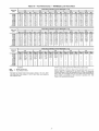
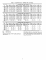
Table 5 -- Electrical Data
NOMINAL
VOLTAGE
UNIT
48TM
VOLTAGE
RANGE
(3 Ph, 60 Hz)
025
RLA
LRA
RLA
LRA
FLA leal
Hp
FLA
253
32.1
195
20.7
156
3
0.5
1.7
5.0
15.8/15.8
460
414
508
16.4
95
10
70
3
0.5
0.8
5.0
7.9
575
518
633
12
80
8.2
54
3
0.5
0.75
5.0
6.0
187
253
30.1
225
28.8
195
3
0.5
1.7
5.0
460
414
508
15.5
114
14.7
95
3
0.5
0.8
5.0
7.9
575
518
632.5
12.1
80
10.7
80
3
0.5
0.75
5.0
6.0
187
253
42
239
33.6
225
2
1
6.6
7.5
460
414
508
19.2
125
17.3
114
2
1
3.3
7,5
13.0
575
518
633
13.8
80.0
13.5
80.0
2
1.0
3.4
7.5
10.0
187.2
253
20.7
156
20.7
156
47.1
245
6
0.5
1.7
10.0
460
414
508
10
75
10
75
19.6
125
6
0.5
0.8
10.0
14.6
575
517.5
632.5
8.2
8.2
54
15.8
100
6
0.5
0.8
10.0
13.0
208/230
028
54
LRA
Qt_/ Hp
LEGEND
FLA
HACR
IFM
LRA
MCA
MOCP
NEC
OFM
RLA
----------
POWER
EXHAUST
IFM
Max
208/230
RLA
OFM
No, 2
187
208/230
020
COMPRESSOR
No. 1A
Min
208/230
016
No, 1
EXAMPLE:
Full Load Amps
Heating, Air Conditioning and Refrigeration
Indoor (Evaporator) Fan Motor
Locked Rotor Amps
MinimumCircuitAmps
Maximum Overcurrent Protection
National Electrical Code
Outdoor (Condenser) Fan Motor
Rated Load Amps
A
B
15.8/15.8
25.0/25.0
28.0/28.0
4.6
2.3
2.1
4.6
2.3
2.1
4.6
2.3
2.1
4.6
LRA
18.8
6.0
4.8
18.8
6.0
4.8
18.8
6.0
4.8
18.8
2.3
2.1
6
4.8
POWER
SUPPLY
FLA
MCA
MOCP*
0.57
82/82
110/110
0.57
86/86
110/110
0.30
41
50
0.30
43
50
0.57
31
40
0.57
34
40
0.57
87/87
110/110
0.57
92/92
110/110
0.30
44
50
0.30
47
60
0.57
34
40
0.57
36
40
0.57
124/124
150/150
0.57
129/129
150/150
0.30
61
80
0.30
63
80
0.57
48
60
0.57
50
60
0.57
138/138
175/175
0.57
143/143
150/175
0.30
64
80
0.30
66
80
0.57
54
60
0.57
56
70
Supply voltage is 460-3-60.
C
AB = 452 v
AC = 455 v
Average Voltage =
BC = 464 v
(_
=--
*Fuse or HACR circuit breaker.
Determine maximum
(AB) 457 - 452 =
(BC) 464 - 457 =
(AC) 457 - 458 =
Maximum deviation
c t oo
452 + 464 + 455
3
1371
3
= 457
deviation from average voltage.
8 v
7 v
2 v
is 7 v.
Determine
percent voltage imbalance.
7
= 100 x--457
= 1.53%
This amount of phase imbalance is satisfactory
allowable 2%.
_IST_O
% Voltage Imbalance
NOTES:
1. In compliance with NEC requirements for multimotor and combination
load equipment (refer to NEC Articles 430 and 440), the overcurrent protective device for the unit shall be fuse or HACR breaker. Canadian units
may be fuse or circuit breaker.
2. Unbalanced 3-Phase Supply Voltage
Never operate a motor wbere a pbase imbalance in supply voltage is
greater than 2%. Use the following formula to determine the percent
voltage imbalance.
% Voltage Imbalance
= 100 x
FLA
COMBUSTION
FAN MOTOR
I
max voltage deviation from average voltage
average voltage
15
as it is below the maximum
contact
your local
company
IMPORTANT:
If theelectric
supply utility
voltage
phase immediately.
imbalance is more than 2%,
I
I
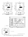
Step 10 -ments
Make
Outdoor-Air
Inlet
Adjust-
OUTDOOR-AIR
HOOD AND
MOUNTING BRACKETS
MANUAL OUTDOOR-AIR
DAMPER -- All units (except
those equipped with a factory-inst_dled economizer)
have a
manual outdoor-air &lmper to provide ventilation ail:
Damper can be preset to admit up to 25% outdoor air into
return-air compartment. To adjust, loosen securing screws and
move &tmper to desired setting, then retighten screws to secure
damper (Fig. 18).
25% ADJUSTABLE
AIR DAMPER
/
FILTER
PACKAGE ANE
HOOD
COMPONENTS
RETURN-AIR
ACCESS PANEL
BASE
UNIT
Fig. 19 -- Outdoor-Air
.HOOD
Hood Component
Location
TOP PANEL
L_
SECURING
Fig. 18-
SCREWS
Standard 25% Outdoor-Air
Section Details
UPPER FILTER.
Step 11 -- Install Outdoor-Air
PAN
Hood
RETAINER
IMPORTANT:
If the unit is equipped with the optional
EconoMiSerIV component, move the outdoor-air temperature sensor prior to installing the outdoor-air hood. See the
Optional EconoMiSerIV
and EconoMiSer2
section for
more information.
X
SEAL B
Fig. 20 -- Seal
The outdoor-air hood is common to 25% air ventilation,
EconoMiSerIV
and EconoMiSer2.
If EconoMiSerIV
or
EconoMiSer2
is used, all electric¢fl connections have been
made and adjusted at the factory. Assemble and install hood in
the field.
Strip
BAFFLE
NOTE: The hood top panel, upper and lower filter retainel_,
hood &'ain pan, baffle (sizes 025 and 028), and filter support
bracket me secured opposite the condenser end of the unit. The
screens, hood side panels, remaining section of tilter suppori
bracket, seal strip, and htudware me in a package located
inside the return-air filter access panel (Fig. 19).
1. Attach seal strip to upper filter retainer. See Fig. 20.
2.
3.
4.
5.
6.
7.
8.
Location
LOWER FILTER
RETAINER
FILTER SUPPORT
BRACKET
Assemble hood top panel, side panels, upper filter retainel: and drgdn pan (see Fig. 21).
Secure lower filter retainer and support bracket to unit.
See Fig. 21. Leave screws loose on 025 and 028 units.
Slide baffle (sizes 025 and 028) behind lower filter retainer and tighten sclews.
Ix_osen sheet metal screws for top panel of base unit
located above outdoor-air
inlet opening, and remove
screws for hood side panels located on the sides of the
outdoor-air inlet opening.
\
\
\
HOOD SIDE
PANELS (2)
\
HOOD TOP
PANEL
BAFFLE
(025 AND
028 ONLY)
Match notches in hood top panel to unit top panel screws.
Insert hood flange between top panel flange and unit.
Tighten screws.
Hold hood side panel flanges flat against unit, and inst_fll
screws removed in Step 5.
Insert outdoor-air
inlet screens and spacer in channel
created by lower filter retainer and filter support bracket.
LOWER
FILTER
RETAINER
BRACKET
HOOD DRAIN PAN
UPPER FILTER RETAINER
Fig. 21 -- Outdoor-Air
16
Hood Details
Step 12 -- Install All Accessories
--
After ;dl the
Accessoiw 0 ° F D_w Ambient Kit -- Install the accessory
low mnbient kit per instruction supplied with accessory.
factory-installed
options have been adjusted, inst;dl all fieldinstalled accessories.
Refer to the accessory
installation
instructions included with each accessory.
MOTORMASTER®
I
CONTROL
INSTALLATION
(48TM016,020,
and 028)
Install Field-Fabricated
Wind Baffles -- Wind baftles must
be field-fabricated
for all units to ensure proper cooling cycle
operation at low mnbient temperatures. See Fig. 22 for baffle
dettfils. Use 20-gage,
galvanized
sheet metal, or similar
conosion-resistant
metal for baftles. Use field-supplied sclews
to attach baffles to unit. Screws should be 1/4-in. diameter and
-s/s-in. long. Drill required screw holes for mounting baffles.
Sensor Assembly -- Install the sensor assembly
shown in Fig. 23.
Motormaster I Control -- Recommended
mounting location is
on the inside of the panel to the left of the control box. The
control should be mounted on the inside of the panel, vertically, with leads protruding from bottom of extrusion.
i:I;o°o
i::_oO
o°
i::_ooo
°
:_:_
o°o
l::_oO
o°
:_:_
o°o
l:l;ooo
°
:_:_o
o°o
i:I;ooo
°
i::_o
o°o
SENSOR--I:_o°O
° SENSOR-LOCAT,ON
:_:_o
CoLOCATION
l:I:o°
o°
I::_
o°o
i::_o°o
°
:_:_o
o°o
i:I:o°O
°
WIND
BAFFLE __
BREAK
BAFFLETOP VIEW 1" (25)MIN--_
80-+.02:(2o62
t_°_----4
/
HAIRPIN END
_--Tt10"
48TM016
(254)
40"
L
(1016
(254)
;(rYP)
"-_-_I_15" (361)
3/4"(19)(YYP)-_
BAFFLEFRONTVIEW
NOTE: Dimensions in ( ) are in ram.
Fig. 22 --
Wind
Baffle
_-
o
_
o
HAIRPIN
END
48TM020
Fig. 23 -- Motormaster®
_10"
j_
,_
SENSOR
LOCATION
o
HAIRPIN END
48TM028
(Circuits 1and 2)
NOTE: All sensors are located on the eighth hairpin up from the
bottom.
(TYP)
--
m
m
----..._.
Install Motormaster
I Controls -- Only one Motormaster
I
control is required for 48TM016 and 020 units. The 48TM028
requires 2 Motormaster
I controls -- one for circuit 1 and
one for circuit 2. The Motormaster I control must be used in
conjunction
with the accessory
0° F low ambient
kit
(purchased sep_uately). The Motorlnaster
[ device controls
outdoor fan no. 1 (and 4 on size 028 units) while outdoor fans
no. 2 and 3 (and 5 and 6 on 028 units) are sequenced off by the
Accessory 0 ° F Low Ambient Kit.
I=
in the location
Motor MountTo ensure proper fan height, leplace the existing motor mount with the new motor mount provided with
accessory.
Trun._wmer (460 and 575-v Units On@) -- On 460 and 575-v
units, a transformer is required. The transformer is provided
with the accesso U and must be field-installed.
To avoid dmnage to the refiigelant coils and electric_d components, use recommended
screw sizes only. Use care
when drilling holes.
___CROSS
0° F
(rYp)
"1" (25) MIN
Details
17
I Sensor Locations
MOTORMASTER®
V
CONTROL
INSTALLATION
(48TM025 Only)
Install Field-Fabricated
Wind Baftles -- Wind baftles must
be tield-fabricated
for all units to ensure proper cooling cycle
operation at low ambient temperatures. See Fig. 22 for baffle
details. Use 20-gage,
galvanized
sheet metal, or similar
corrosion-resistant
metal for baffles. Use field-supplied screws
to attach baffles to unit. Screws should be l/4-in, diameter and
s/g-in, long. Dill required screw holes for mounting baffles.
FROM FUSE BLOCK
60606
ii
1.2
i,,i
o
o
To avoid dmnage to the refiigerant coils and electrical components, use recommended
screw sizes only. Use cme
when di'illing holes.
B
13B
12
Install Motormaster
V Controls
-The Motormaster
V
(MMV) control is a motor speed control device which adjusts
condenser fan motor speed in response to declining liquid
refrigerant pressure. A properly applied Motormaster V control
extends the operating range of air-conditioning
systems and
permits operation at lower outdoor ambient temperatures.
The minimum
operate are:
mnbient temperatures
Unit
40
(4)
13C
_'oc_ooo
TOPRESSURE.
TRANSDUCER
m[
GI_)I/y[[
at which the unit will
TO MOTOR(S)
TEMPERATURE
Standard
13A I
OPERATING
Unit with
Low Ambient
25 (-4)
Kit
LIMITS -I
I
Fig. 24 -- Motormaster®
F° (C °)
Unit with
MMV
-20 Control
(-29)
Table 6 --
To operate down to the ambient
telnpemtures
listed,
Motorlnaster
V controls (Fig. 24) must be added. Fieldfabricated and inst_dled wind baffles are also required for all units
(see Fig. 22). The Motormaster V control permits operation of
the unit to an ambient temperature of-20 F (-29 C). The control
regulates the speed of 3-phase fan motors that are compatible
with rite control. These motol_ zue factory installed.
UNIT
48TM016-028
V control
per instructions
V Control
VOLTAGE
208/230-3-60
460-3-60
575-3-60
supplied
18
Package
Usage
VOLTAGE
ITEM DESCRIPTION
208/230
CRLOWAMB015AOO
460
CRLOWAMB016A0O
575
CRL©WAMBO17AOO
Table 7 -- Applicable
See Table 6 for the Motorlnaster
V control accessory
package usage. Table 7 shows applicable voltages and motors.
Replacement
of fan motor IS NOT
REQUIRED
ON
CURRENT
PRODUCTION
UNITS since the control is
compatible with the factory-installed
fan motors. Only field
wiring control is required.
Inst_dl the Motormaster
with accessory.
Motormaster
V Control
Voltages
and Motors
COMPATIBLE MOTOR
HDS2AK654
HD52AK654
HD52GE576
Step 13 --Adjust
Factory-Installed
Options
into the fan section, down along the back side of the fan, and
_dong the fan deck over to the supply-air opening.
The SAT probe is wire-tied to file supply-air opening (on the
horizontal opening end) in its shipping position. Remove the
sensor for installation. Re-position the sensor in the flange of
the supply-air opening or in the supply air duct (as required by
local codes). Drill or punch a l/2-in, hole in the flange or duct.
Use two field-supplied, self-drilling screws to secme the sensor
probe in a horizontal orientation.
PREMIERLINK
TM CONTROL
-- The PrelnierLink controller is available as a special order from the facto U and is
compatible with the Carrier Comfort Network® (CCN) system. This control is designed to allow usel_ the access and abilfly to change factou-defined
settings, thus expanding the function of the standmd unit control bomd. CmTier's diagnostic
standard tier display tools such as Navigator r_'_ device or
Scrolling
Marquee
can be used with file PremierLink
controllel:
NOTE: The sensor must be mounted in the dischmge airstream
downstream of the cooling coil and any heating devices. Be
sure the probe tip does not come in contact with any of the unit
or heat surfaces.
The PremierLink controller (see Fig. 25) requires the use of
a CmTier electronic thermostat or a CCN connection for time
broadcast to initiate its internal timeclock. This is necessa U for
broadcast of time of day functions (occupied/unoccupied).
No
sensors are supplied with the field-mounted
PremierLink
control. The factory-installed
PremierLink
control includes
only the supply-air temperature (SAT) sensor and the outdoor
air temperature (OAT) sensor as standard. An indoor air quality
(CO2) sensor can be added as an option. Refer to Table 8 for
sensor usage. Refer to Fig. 26 for PremierLink
controller
wiring. The PremierLink
control may be mounted in the
control panel or an area below the control panel.
Outdoor Air Temperature
(OAT) Sensor -- When the unit is
supplied with a factory-mounted
PremierLink
control, the
outdoor-air temperature sensor (OAT) is factory-supplied
and
wired.
Install the Indoor Air Quality (CO2) Sensor -optional indoor air quality (CO2) sensor according
turer specifications.
A sepmate field-supplied
transformer
must be used to
power the CO2 sensol:
Wire the C(_ sensor to the COM and IAQI terminals of J5 on
file PremierLink controflel: Refer to file PremierLink Installation, Start-up, and Configuration Instructions for detailed wiring
and configuration information.
NOTE: PremierLink controller version 1.3 and later is shipped
in Sensor mode. If used with a thermostat, the PremierLink
controller must be configured to Thermostat mode.
Install the Supply Air Temperature
(SAT) Sensor -- When
the unit is supplied with a factou-mounted
PremierLink control, the supply-tdr temperature (SAT) sensor (33ZCSENSAT)
is factory-supplied
and wired. The wiring is routed fi_m the
PremierLink control over the control box, through a grommet,
HVACSENSOR INPUTS
0
O
SPACE'rEMP
_ h'q'
Mount the
to manufac-
¢
................................
TS_T_
SET POINT -._._ L=]_ I
SUPPLY AIR TEMP _
OUTDOOR
TEMP _
_lil
_
INDOOR
AIR QUALITY
_
LT_
OUTDOOR
AIR QUALITY
_
_!]
DUAL MODE SENSOR (STAT)
IJ_
7H: I
COMP SAFETY (Y1) /'_H
FIRE SHUTDOWN
_
_
o
_.2_.,
Premiertink
Ili]
; ]
.
_' I
°°' -
(Y2) /
SUPPLY
FAN STATUS (Wl) Ja"H
i I
NOT USED (W2) "/'r Iq • I
ENTHALPY
STATUS (ENTH) ../_]_ltot
....
[--]
, ,r"l ,o i-Ior__ ,,= . I ,,-°_-- I I
I [] FTfil U'_l-GqEZZ]hi"W'q_t_'T_q-_f!
,/i1[=-°. --toltio-q.t
/
CCN/LEN
PORT
/
)I
NAVIGATOR
PORT
4 20MA/
ECONOMIZER
t
INDOOR
FAN MOTOR
'_
COMPR
1& 2
OUTPUTS
Fig. 25 -- PremierLink Controller
19
"_._
'_
HEAT
LOW/HIGH
EXHAUST
RVS VALVE
e
,_
BLUE
_LU
BRN
_RN
BLK
GRN .....
_
t
_
PL1 - 5
BRN
_
PL1 - 6
VIO
PremierLink
Control
_LK
COM
BRN
• ORN
BRN
_R_
SAT
CON
_o
VIO
BRN
BRN
tOM
RE_ _
RED --
COM
[oc
CONTROL
OAT
GRN_
RED
--
Pi K
YEL
GRN
iRED
YEL
RED
RED
BLu
_@
_
....
BLO
BLU
_LU
£EO FT
RED
FSD
WHT
WHT
RED T
RED
_
PNK
--
Y2
W2
--
--
--
×
CLO1
CONTROL
CMP
SAFE
TB2
R
Y1
TSTAT
Y1
FSD
Y2
SFS
Wl
Wl
W2
W2
Y2
CONTROL
ni!
IlLUL
U
'_THEFIELDTAT
Y_
_ ]
I
C_
_
_
RMTCCC
G
G
C
C
C
X
X
X
(_
FRONM]_4V
=_)
NOT USED
NOT[
USED
.....
1
G
DDC
ECONO
Y1
Wl
G
OaN
RED
RED
R
ECONOMIZER
50TJ401148
(CRECOMZROIOB00)
@
TB21-
3
4-20rr_
ECONO
1
MOTOR
_T
F!R_1i
FROM
_Qc-a
CLO
-CMP
-ECONO-ENTH
-IGC
-MGV
-OAT
-PL
-SAT
-SPT
-TB
--
Fii i
iiiM_r
rviRvl_O_2
_C'_DR
LEGEND
Compressor Lockout
Compressor
Economizer
Enthalpy Sensor
Integrated Gas Unit Controller
Main Gas Valve
Outdoor Air Temperature Sensor
Plug
Supply Air Temperature Sensor
Space Temperature Sensor
Terminal Block
*If PremierLink control is in thermostat mode.
1-TB2 terminal designations for 24 vac discrete
inputs. Default is for DDC control.
Fig. 26 -- Typical PremierLink
TM
Controls Wiring
Table 8 -- PremierLink
APPLICATION
OUTDOOR AIR
TEMPERATURE SENSOR
Differential Dry Bulb
Temperature with
PremierLink*
(PremierLink
requires 4-20 mA
Actuator)
Single Enthalpy with
PremierLink*
(PremierLink
requires 4-20 mA
Actuator)
Differential Enthalpy
with PremierLink*
(PremierLink
requires 4-20 mA
Actuator)
TM
Sensor
Usage
RETURN AIR
TEMPERATURE SENSOR
OUTDOOR AIR
ENTHALPY SENSOR
RETURN AIR
ENTHALPY SENSOR
Required -33ZCT55S PT
--
--
--
Required -33CSENTHSW
(HH57ZC003)
or
HH57AC077
--
--
Required -33CSENTHSW
(HH57ZC003)
or
HH57AC077
Required33CSENTSEN
or
HH57AC078
Included -HH79NZ039
or Equivalent
Included -Not Used
Included -Not Used
*PremierLink control requires supply air temperature sensor 33ZCSENSAT and
outdoor air temperature sensor HH79NZ039 -- Included with factory-installed PremierLink control;
field-supplied and field-installed with field-installed PremierLink control.
NOTES:
1. CO2 Sensors (Optional):
33ZCSENCO2 -- Room sensor (adjustable). Aspirator box is required for duct mounting of the sensor.
33ZCASPCO2 -- Aspirator box used for duct-mounted CO2 room sensor.
33ZCT55CO2 -- Space temperature and CO2 room sensor with override.
33ZCT56CO2 -- Space temperature and CO2 room sensor with override and setpoint.
2. All units include the following standard sensors:
Outdoor-air sensor -- 50HJ540569 -- Opens at 67 F, closes at 52 F, not adjustable.
Mixed-air sensor -- HH97AZ001 -- (PremierLink control requires supply air temperature sensor 33ZCSENSAT
and outdoor air temperature sensor HH79NZ039)
Compressor lockout sensor -- 50HJ540570 -- Opens at 35 F, closes at 50 E
ENTHALPY SWITCH/RECEIVER
-- The accessory
enthalpy switch/receiver
(33CSENTHSW)
senses temperature
and humidity of the air surrounding the device trod calculates
the enthalpy when used without an enthalpy sensol: The relay is
energized when enth_flpy is high and deenergized
when
enthalpy is low (based on ASHRAE [American Society of
Heating, Refrigeration and Air Conditioning Engineersl 90.1
criteria). If an accessory enthalpy sensor (33CSENTSEN)
is
attached to the return air sensor input, then differential enthalpy
is c_flculated. The relay is energized when the enthalpy detected
by the leturn air enthalpy sensor is less than the enth_flpy at the
enthalpy switchheceivel:
The relay is deenergized when the
enth_flpy detected by the leturn air enthalpy sensor is gleater
than the enthalpy at the enflmlpy switch/receiver
(differential
enth_flpy control). See Fig. 27 and 28.
intake). The enthalpy switch/receiver
is not a NEMA 4
(Natiomd Electrical Manufacturers
Association) enclosure and
should be mounted in a location that is not exposed to outdoor
elements such as rain or snow. Use two field-supplied no. 8 x
3/4-in. TEK screws. Insert the screws through the holes in the
sides of the enthalpy switch/receivel:
Wiring -- Cmrier recommends
the use of 18 to 22 AWG
(American Wire Gage) twisted pair or shielded cable for all
wiring. All connections must be made with l/4-in, female spade
connectors.
A 24-vac transformer is required to power the enthalpy
switch/receiver; as shown in Fig. 29. the PremierLink TM board
provides 24 vac. Connect the GND and 24 VAC terminals on
the enthalpy switch/receiver to the terminals on the transformer. On some applications,
the power from the economizer
harness can be used to power the enthalpy switch/receivel:
To
power the enthalpy
switch/receiver
from the economizer
harness, connect power of the enthalpy switch/receiver
to the
red and brown wires (1 and 4) on the economizer harness.
OUTDOOR
ENTHALPY
CONTROL
(Fig. 29) -Outdoor enthalpy control lequires only an enth_flpy switch/
receiver (33CSENTHSW).
The enthalpy switch/receiver
is
mounted in the outdoor air inlet and c_dculates outdoor air
enthalpy. The enthalpy switch/receiver
energizes the relay
output when the outdoor enth_flpy is above 28 BTU/Ib OR din
bulb temperature
is above 75 F and is deenergized
when
the outdoor enthalpy is below 27 BTU/Ib AND dry bulb
temperature is below 74.5 E The relay output is wired to the
unit economizer which will open or close depending on the
output of the switch.
NOTE: The enthalpy calculation
altitude of 1000 ft above sea level.
is done
For connection to rooftop units with PremierLink TM control,
connect the LOW Enthalpy terminal on the enthalpy switch/
receiver to J4 -- pin 2 of the PremierLink
control on the
HVAC unit. The switch can be powered through the PremierLink control board if desired. Wire the 24 VAC termimfl on the
enth_flpy switch/receiver
to J4 -- pin 1 on the PremierLink
control. Wire the GND terminal on the enthalpy switch/
receiver to Jl -- pin 2 on the PremierLink
control. The HI
Enth_flpy terminal is not used. See Fig. 29.
using an average
Mounting -- Mount the enthalpy switch/receiver
in a location
where the outdoor air can be sampled (such as the outdoor air
21
4253"
(108 03mm)
4 253"
(I 08 03rnm)
\
25"---_.35rnm)
,25"
(6.35mm)
2_
c
N
/
Fig. 27 -- Enthalpy Switch/Receiver
(33CSENTHSW)
_N
/
Dimensions
Fig. 28 -- Enthalpy Sensor Dimensions
(33CSENTSEN)
O
O €
{..........................
I
I
TS_A_r
C_
i
__
BLU
Bu<L.----a_
_
-4=
.4
_
.... __=22_c_.L%. -
ya. -
PartNumber; 33CSPREMLK
.
/
(/
.................
_-____. _,,
,_1
I
,
,-o 1o! Prem,erLznk_,._,
i
RAq4
J2
_ _
o
[]
_
O
J_
r_E_
.._
-_
_
Ja
I .....
_
.,__
_o
e I ......
,,,,..
,_
I ......
_
,,.o
I
/
o
........
l(OR
UNIT GROUND)
\
*Used with Differential Enthalpy Control only.
Fig. 29 -- Typical Wiring Schematic -- Carrier Rooftop Unit with PremierLink
22
TM
Controls
DIFFERENTIAL
ENTHALPY
CONTROL
(Fig. 30) -Diffemnti_d enthalpy control mquiles both an enth_dpy switch/
receiver
(33CSENTHSW)
and
an
enth_dpy
sensor
(33CSENTSEN).
The enthalpy switchheceiver
is mounted in
the outdoor air inlet and calculates outdoor air enthalpy. Tile
enthalpy sensor is mounted in the return airstream and c_flculates the enthalpy of the indoor all:
the transformer
On some applications,
the power from the
economizer hmness can be used to power the enthalpy switch/
receivec To power the enthalpy switch/receiver from the economizer hmness, connect power of the enthalpy switch/receiver
to the led and brown wires (1 and 4) on the economizer
harness.
Connect the LOW Enthalpy
terminal on the enthalpy
switch/receiver to J4 -- pin 2 of the PlemierLink control on the
HVAC unit. The switch can be powered through the PremierLink control board if desired. Wire the 24VAC terminal on the
enthalpy switclffreceiver to J4 -- pin 1 on the PremierLink
control. Wire the GND terminal on the enthalpy switch/
receiver to Jl -- pin 2 on the PremierLink
control. The HI
Enthalpy terminal is not used. See Fig. 29.
The enthalpy switch/receiver
enelgizes the HI Enthalpy
relay output when file outdoor enthalpy is gleater than the
indoor enth_flpy. The LOW Enthalpy terminal is energized
when the outdoor enthalpy is lower than the indoor enthalpy.
The relay output is wired to the unit economizer which will
open or close depending on the output of the switch.
NOTE: The enthalpy calculation
altitude of 1000 fl above sea level.
is done
using an average
Connect the 4-20 mA IN terminal on the enthalpy switch/
receiver to the 4-20 mA OUT terminal on the return air
enthalpy sensol: Connect the 24-36 VDC OUT terminal on the
enthalpy switch/receiver to the 24-36 VDC IN terminal on the
return air enthalpy sensor. See Fig. 30.
Mounting -- Mount the enthalpy switch/receiver
in a location
where the outdoor air can be sampled (such as the outdoor air
intake). The enthalpy switch/receiver
is not a NEMA 4 enclosure grad should be mounted in a location that is not exposed to
outdoor elements such as rain, snow. or dilect sunlight. Use
two field-supplied no. 8 x 3/4-in. TEK screws. Insert the screws
through the holes in the sides of the enthalpy switclffreceivel:
Enthalpy Switch/Receiver
Jumper Settings -- There are two
jumpers. One jumper determines the mode of the enthalpy
switch/receivel:
The other jumper is not used. To access the
jumpers,
lemove the 4 screws holding the cover on the
enthalpy switclffreceiver
and then remove the covel: The
factory settings for the jumpel.'s are M 1 and OFF.
Mount the enthalpy sensor in a location whele the indoor air
can be smnpled (such as the return air duct). The enthalpy
sensor is not a NEMA 4 enclosure and should be mounted in a
location that is not exposed to outdoor elements such as rain or
snow. Use two field-supplied no. 8 x 3/4-in. TEK screws. Insert
the screws through the holes in the sides of the enthalpy sensol:
The mode jumper should be set to M2 for differential
enthalpy control. The factory test jumper should lemain on
OFF or the enthalpy switch/receiver will not calculate enthalpy.
Wiring -- Carrier recommends
the use of 18 to 22 AWG
twisted pair or shielded cable for all wiring. All connections
must be made with 1/4-in. female spade connectors.
Enthalpy Sensor Jumper Settings -- There are two jumpers.
One jumper determines the mode of the enthalpy sensol: The
other jumper is not used. To access the jumpel.s, remove the
4 screws holding the cover on the enthalpy sensor and then
remove the covel: The factory settings for the jumpers are M3
and OFF.
The PremierLink TM bom'd provides 24-vac to power the
enthalpy switch/receivel:
Connect the GND and 24 VAC
terminals on the enthalpy switch/receiver
to the terminals on
120 VAC
LINE VOLTAGE
_a....A....AJ--
24 VAC OUTPUT FROM N/C CONTACT WHEN THE
OUTDOOR ENTHALPY IS LESS THAN THE
INDOOR ENTHALPY
_ ORN
(ENABLE ECONOMIZER)
f
f
/
\\
24 VAC OUTPUT FROM N/O CONTACT WHEN THE 4INDOOR ENTHALPY IS GREATER THAN THE
OUTDOOR ENTHALPY
/
J
[
HI LOWGND
ENTHALPY
_
24
VAC
4-20 24-36
mA VDC
IN OUT
33CSENTHSW
24-36 4-20
VDC mA
IN
OUT
"_,
33CSENTSEN
J
JUMPER SETTINGS
FOR 33CSENTHSW
O
LEGEND
N/C -N/O --
Normally Closed
Normally Open
o
JUMPER SETTINGS
on
(DII(D
[o
o] Ilooo
o
(DO
Fig. 30 -- Differential Enthalpy Control Wiring
23
FOR 33CSENTSEN
O
o
on
[11oo
°°I 11o
°o°o°
The mode jumper should be set to M3 for 4 to 20 mA
output. The factory test jumper should remain on OFF or the
enthalpy sensor will not calculate enthalpy.
ENTHALPY
CONTROLLER
RED
A(_C
ENTHALPY SENSORS AND CONTROL
-- The enthalpy
control (HH57AC077)
is supplied as a field-installed accessory
to be used with tile EconoMiSer2 damper control option. Tile
outdoor air enthalpy sensor is part of the enthalpy control. The
separate field-installed
accessory return air enthalpy sensor
(HH57AC078)
is required for differential enthalpy control.
TRr'_TR 1[_sol:3
÷l-q
BLK
RED
BRN
AIR
+ ENTHALPY
(OUTDOOR
SENSOR)
-_S
I--IS (RETURN AIR
F[ + ENTHALPY
sRrh +H---q '
--
SENSOR)
GRAY/ORN
LWIRE
LED
NOTE: The enthalpy control must be set to the "D" setting for
differential enthalpy control to work properly.
GRAY/RED
JIN
HARNESS
UNIT
NOTES:
1. Remove factory-installed
jumper across SR and + before connecting wires from return air sensor.
2, Switches shown in high outdoor air enthalpy state. Terminals 2
and 3 close on low outdoor air enthalpy relative to indoor air
enthalpy,
3. Remove sensor mounted on back of control and locate in outside airstream.
The enthalpy control receives
the indoor and return
enthalpy from the outdoor and return air enthalpy sensors and
provides a dry contact switch input to the PremierLink TM
controllec Locate the controller in place of an existing economizer controller or near the actuatol: The mounting plate may
not be needed if existing bracket is used.
A closed contact indicates that outside air is prefened to the
return aic An open contact indicates that the economizer
should remain at minimum position.
Fig. 31 -- Outdoor and Return Air Sensor Wiring
Connections for Differential Enthalpy Control
Outdoor
Air
Enthalpy
Sensor/Enthalpy
Controller
(HH57AC077)
-- To wire the outdoor air enthalpy sensor.
perform the following (see Fig. 31 and 32):
NOTE: The outdoor air sensor can be removed from the back
of the enthalpy controller and mounted remotely.
HH57AC077
ENTHALPY
CONTROLAND
OUTDOOR AIR
ENTHALPY SENSOR
1. Use a 4-conductor:
18 or 20 AWG cable to connect the
enthalpy control to the PremierLink controller and power
tmnsformec
2.
Connect the following 4 wires from the wire hmness
located in rooftop unit to the enthalpy controller:
a. Connect the BRN wire to the 24 vac terminal (TRI)
on enthalpy control and to pin 1 on 12-pin harness.
b. Connect the RED wire to the 24 vac GND terminal
(TR) on enthalpy sensor and to pin 4 on 12-pin
harness.
c. Connect the GRAY/ORN
wire to J4-2 on PremierLink controller and to terminal
(3) on enthalpy
sensoE
d. Connect the GRAY/RED
wire to J4-1 on PremierLink controller and to terminal (2) on enthalpy sensol:
HH57AC078 ENTHALPY
SENSOR(USED
WITH
ENTHALPY CONTROL
FOR DIFFERENTIAL
ENTHALPY OPERATION)
NOTE: If installing in a Carrier rooftop, use the two gray wires
provided from the control section to the economizer to connect
PremierLink controller to terminals 2 and 3 on enth_dpy sensol:
÷
Return Air Enthalpy Sensor -- Mount the return-air enthalpy
sensor (HH57AC078)
in the return-air duct. The return air
sensor is wired to the enth_dpy controller (HH57AC077).
The
outdoor enth_dpy changeover set point is set at the controller.
÷
MOUNTING
PLATE
Fig. 32 -- Differential Enthalpy Control,
Sensor and Mounting Plate (33AMKITENT006)
To wire the return air enthalpy sensol: perform the following (see Fig. 31 ):
1. Use a 2-conductor.
18 or 20 AWG. twisted pair cable to
connect the return air enthalpy sensor to the enthalpy
controller.
To complete inst_dlation of the optional EconoMiSerIV. perform the following procedure.
1. Remove the EconoMiSerIV hood. Refer to Step 11 --Install Outdoor-Air
Hood on page 16 for information on
removing and installing the outdoor-air hood.
2.
At the enthalpy control remove the factory-installed
resistor from the (SR) and (+) termin;ds.
3. Connect the field-supplied
RED wire to (+) spade
connector on the return air enthalpy sensor and the (SR+)
terminal on the enth_flpy controllel: Connect the BLK
wire to (S) spade connector on the return air enthalpy
sensor and the (SR) terminal on the enthalpy controllo:
OPTIONAL
ECONOMISERIV
AND ECONOMI$ER2
-See Fig. 33 and 34 for EconoMiSerlV
component locations.
See Fig. 35 for EconoMiSer2 component locations.
2.
Relocate
position
Fig. 33.
outdoor air temperature sensor from shipping
to operation position on EconoMiSerIV.
See
EconoMiSerIVFailure
not operating
I the
MPORTANT:
to relocate properly.
tile sensor will result in
NOTE: These instructions
are for installing the optional
EconoMiSerlV
and EconoMiSer2 only. Refer to the accessory
EconoMiSerIV
or EconoMiSel2
installation instructions when
field installing an EconoMiSerIV
or EconoMiSer2 accessory.
24
3.
Reinst_dl economizer
hood.
4.
Install all EconoMiSerIV
accessories.
wiring is shown in Fig. 36. EconoMiSer2
in Fig. 37.
EconoMiSeltV
wiring is shown
Outdoor
airleakage
isshown
inTable
9.Return
airpressure
dropisshown
inTable10.
Table 9 -- Outdoor
Return
Air Pressure
ECONOMI$ER2
SCREWS
Leakage
DAMPER STATIC PRESSURE (in. wg)
0.2
0.4
0.6
0.8
1.0
1.2
35
53
65
75
90
102
LEAKAGE (cfm)
Table 10-
Air Damper
FRAME
SCREWS"
_):
1
_f'_
Drop (in. wg)
CFM
_J
4500 5000
5400
6000
7200 7500
9000 10,000 11,250
0.040
0.060
0.070
0.090
0.110
0.050
0.100
0.120
OUTDOOR
ECONOMI$ERIV
FRAME
i_j_ '
SCREWS
ECONOMISERIV
AIR
TEMPERATURE
SCREWS
Fig. 35 -- EconoMiSer2
0.140
(INSTALLED
POSITION)
Fig. 33--EconoMi$erlVComponent
End View
SWITCH
The temperature sensor looks like an eyelet terminal with
wires running to it. The sensor is located in the "crimp end"
and is sealed from moisture.
Locations--
SUPPLY
AIR
TEMPERATURE
LOCATION
SENSORS
Supply Air Temperature
(SAT) Sensor
-- The supply air
temperature sensor is a 3 K thermistor located at the inlet of the
indoor fan. See Fig. 34. This sensor is factory installed. The operating range of temperature measurement is 0 ° to 158 E See
Table 11 for sensor temperature/resistance
values.
TEMPERATURE
COMPRESSOR
LOCKOUT
Locations
Outdoor Air Temperature
(OAT) Sensor -- The outdoor air
temperature sensor (HH57AC074)
is a 10 to 20 mA device
used to measure the outdoor-_dr temperature. The outdoor air
temperature is used to determine when the EconoMiSerIV
c_m
be used for free cooling. The sensor must be field-relocated.
See Fig. 33. The operating range of temperature measurement
is 40 to 100 E
SENSOR
OPERATION
LOW
STANDARD
Component
Ix)w Temperature Compressor Lockout Switch -- The EconoMiSerIV is equipped with an mnbient temperatme lockout
switch located in the outdoor aiLstremnwhich is used to lockout
the complessoLs below a 42 F mnbient temperatme. See Fig. 33.
SENSOR
Table 11 -- Supply Air Sensor Temperature/
Resistance Values
TEMPERATURE
-58
100,680
-22
53,010
-4
29,091
14
16,590
32
9,795
50
5,970
68
3,747
77
3,000
86
2,416
104
1,597
F
122
140
1,080
746
Locations--
158
525
176
376
185
194
321
274
212
203
230
153
248
116
257
102
266
284
89
70
302
55
FLANGE
(HIDDEN)
EconoMi$erlV
Component
Side View
RESISTANCE (ohms)
200,250
-40
ECONOMI$ERIV
Fig. 34--
(F)
25
YZL
PNK
BLU
RED
--
OR N
,.ELD
i
ACCESSORY}
RZWOTE I_IN
POSITION POT
E,R
[]
BLK
SENSOR {Sk O_m)
DISCHARGE AIR
----I_R
A-
2V
POS
oPE,
_.li_
_
L_BEK
I
PLI "R
e- (NOT USED)
FIELD
I
II_STALLED
SET
IDV
_
_----]
[]DCA_
IAQSENSOR.J;,"_.l (. )
I
RV
IRV
PL1-9
I
ERTOA_
0
_V T
PL1-8
(
TO MAIN
CONTROL
B0x
PL1-5
I I
L___,LT"
RETURR AIR TEMPI
[.THALPY SENSOR
I I
PLI=I
(
PDT_R
P_I"10
(NOT USED)
I I
BLU
I
PNK--_
I
l_ISR*
I_
DCV -- Demand Controlled Ventilation
IAQ -- Indoor Air Quality
LALS-Low Temperature Compressor
Lockout Switch
OAT -- Outdoor-Air Temperature
POT -- Potentiometer
_(.
I I FIELD SPLICE
L I
BRN
II
FIELD
RED
LALS
I
SPLICE
ECONOMIZER
LEGEND
_REE
COOL
_
Potentiometer Default Settings:
Power Exhaust
Middle
Minimum Pos.
Fully Closed
DCV Max.
Middle
DCV Set
Middle
Enthalpy
C Setting
MOTOR
NOTES:
1, 620 ohm, 1 watt 5% resistor should be removed only when using differential
enthalpy or dry bulb.
2. If a separate field-supplied 24 v transformer is used for the IAQ sensor power
supply, it cannot have the secondary of the transformer grounded.
3. For field-installed
remote minimum position POT, remove black wire jumper
between P and P1 and set control minimum position POT to the minimum
position.
Fig. 36 -- EconoMi$erlV Wiring
4
3
7
RED
2
500 OHM
8
RESISTOR-
"h_
PINK
6
NOTE 1
BLUE
5
OAT
BLACK
1
NOTE 2
J
10
50HJ540573
ACTUATOR
ASSEMBLY
11
9
WHITE
DIRECT
DRIVE
ACTUATOR
12
ECONOMI$ER2
LEGEND
OAT -- Outdoor Air Temperature Sensor
NOTES:
1. Switch on actuator must be in run position for economizer to operate.
2. 50HJ540573 actuator consists of the 50HJ540567 actuator and a harness with 500-ohm
Fig. 37 -- EconoMi$er2
26
resistor.
Wiring
PLUG
ECONOMI$ERIV
CONTROL MODES
EXHAUST
FAN SET POINT
LED LIGHTS
WHEN EXHAUST
CONTACT tS MADE
a controllel: The EconoMiSer2 is opelated by a 4 to 20 mA
signal from an existing field-supplied controller (such as
IMPORTANT:
optional
doesinformation.
not include
PremierLink TM The
control).
See EconoMiSer2
Fig. 37 for wiling
MINIMUM DAMPER
POSITION SETTING
MAXIMUM DAMPER
DEMAND CONTROL
VENTILATION
SET POINT
Determine the EconoMiSerIV control mode before set up of
the control. Some modes of operation may lequile diffelent sensol.s. Refer to Table 12. The EconoMiSerIV is supplied from file
factory with a supply air temperatme sensor, a low temperature
complessor lockout switch, and an outdoor air temperature sensol: This _dlows for opelation of the EconoMiSerIV with outdoor air dly bulb changeover control. Additiomd accessories
can be added to allow for different types of changeover control
and operation of file EconoMiSerIV and unit.
Table 12 -- EconoMi$erlV
APPLICATION
LED LIGHTS WHEN
OUTDOOR AIR IS
SUITABLE FOR
FREEOOO ' JOL,NG,ENTHA
ECONOMI$ERIV WITH OUTDOOR
DRY BULB SENSOR
CHANGEOVER
AIR
Fig. 38 --
Required
Outdoor Air
Dry Bulb
Differential
Dry Bulb
None. The outdoor air dry bulb sensor
is factory installed.
Single Enthalpy
HH57AC078
Differential
Enthalpy
HH57AC078
and
CRENTDIF004A00*
CO2 for DCV
Control using a
Duct-Mounted
CO2 Sensor
DEMAND CONTROL
VENTILATION SET POINT
Sensor Usage
Accessories
CO2 for DCV
Control using a
Wall-Mounted
CO2 Sensor
LED LIGHTS WHEN
DEMAND CONTROL
VENTILATION
INPUT
IS ABOVE SET POINT
SET POINT
EconoMiSerlV
Controller
and LED Locations
Potentiometer
CRTEMPSN002A00*
19
18
+'%.,,, LEDON
16- --
LED ON
- LED OFF
15
33ZCSENCO2
I
13
12
and
33ZCSENCO2133ZCASPCO2**
CRCBDIOX005A001-1-
-LED OFF_h
LED ON-- --
11
1_
10
*CRENTDIF004A00
and CRTEMPSN002A00
accessories
are
used on many different base units. As such, these kits may contain parts that will not be needed for installation.
1-33ZCSENCO2 is an accessory CO2 sensor.
**33ZCASPCO2
is an accessory aspirator box required for ductmounted applications.
1-1-CRCBDIOX005A00
is an accessory
that contains
both
33ZCSENCO2 and 33ZCASPCO2 accessories.
9
4O
45
50
55
60
65
70
75
80
85
90
95
DEGREES FAHRENHEIT
Fig. 39 -- Outside Air Temperature
Changeover Set Points
Outdoor Dry Bulb Changeover
-- The smn&ud controller is
shipped from the factory configured
for outdoor dry bulb
changeover control. The outdoor air and supply air temperature
sensors are included as stan&u'd. For this control mode, the
outdoor temperature is compaled to an adjustable set point
selected on the control. If file outdoor-air temperature is above
the set point, the EconoMiSerIV
will adjust the outdoor-air
dampers to minimum position. If the outdoor-air temperatme is
below the set point, the position of the outdoor-air dampel.s will
be controlled to provide free cooling using outdoor air When
in this mode, file LED next to the free cooling set point potentiometer will be on. The changeover
temperature set point is
controlled by the free cooling set point potentiometer
located
on the control. See Fig. 38. Tile scale on the potentiometer is A,
B, C, and D. See Fig. 39 for the corresponding
temperature
changeover values.
Differential Dry Bulb Control -- For differential @ bulb
control the stan(lard outdoor dry bulb sensor is used in conjunction with an additional accessory return air sensor (p_u-tnumber
CRTEMPSN002A00).
Tile accessory sensor must be mounted
in the return airstream. See Fig. 40.
In this mode of operation, the outdoor-air temperature is
compared to the return-air temperature and the lower temperature airstream is used for cooling. When using this mode of
changeover control, turn the free coolin_enthalpy
set point
potentiometer fully clockwise to the D setting. See Fig. 38.
IAQ
SENSOR
RETURN
AIR
TEMPERATURE
OR ENTHALPY
SENSOR
Fig. 40 -- Return Air Temperature or
Enthalpy Sensor Mounting Location
27
100
Outdoor Enthalpy Changeover
-- For enthalpy control, accessoq
enthalpy
sensor (part number
HH57AC078)
is
required. Replace the stan&ud outdoor dry bulb temperature
sensor with the accessory enthalpy sensor in the same mounting location. See Fig. 33. When the outdoor air enthalpy rises
above the outdoor enthalpy changeover set point, the outdoorair damper moves to its minimum position. The outdoor
enthalpy changeover set point is set with the outdoor enthalpy
set point potentiometer on the EconoMiSerIV
controllel: The
set points are A, B, C, and D. See Fig. 41. The factory-installed
620-ohm jumper must be in place across terminals SR and SR+
on the EconoMiSerIV controllel: See Fig. 33 and 42.
enter the building. Make minimum position adjustments with
at least 10° F temperature difference between the outdoor and
return-air temperatures.
To determine the minimum
following procedure:
resistor if differential
enthalpy
using the
TR = Return-Air Temperature
RA = Percent of Return Air
TM = Mixed-Air
Temperature
As an example, if local codes require 10% outdoor
during occupied conditions, outdoor-air temperature
60 IF.and return-air temperature is 75 F.
air
is
(60 x. 10) + (75 x .90) = 73.5 F
2.
Disconnect
TI.
the supply-air
3.
Ensure that
terminals P
used, make
Fig. 36 and
turned fully
Connect 24
the factory-installed jumper is in place across
and PI. If lemote &_mper positioning is being
sure that the termimfls are wired according to
that the minimum position potentiometer
is
clockwise.
vac across termin_ds TR and TRI.
4.
sensor from terminals
T and
5.
Cmefully adjust the minimum position potentiometer
until the measured mixed-air temperature matches the
c_dculated v_due.
6.
Reconnect
sen-
Indoor Air Quality (IAQ) Sensor Input -- The IAQ input
can be used for demand control ventilation control based on the
level of CO2 measured in the space or return air duct.
the supply-air
sensor to terminals
T and TI.
Remote control of the EconoMiSerIV
dalnper is desirable
when
requiring
additional
temporary
ventilation.
If a
field-supplied remote potentiometer (Honeywell part number
$963B1128) is wired to the EconoMiSerIV
controller, the minimum position of the &lmper can be controlled from a remote
location.
Mount the accessory IAQ sensor according to manufacturer
specifications. The IAQ sensor should be wired to the AQ and
AQI terminals of the controllel: Adjust the DCV potentiometers to correspond to the DCV voltage output of the indoor air
quality sensor at the user-determined
set point. See Fig. 43.
To control the minimum damper position remotely, remove
the factory-installed jumper on the P and PI terminals on the
EconoMiSerIV
controllel: Wire the field-supplied potentiometer to the P and PI terminals on the EconoMiSerlV
controller
See Fig. 40.
If a sep_uate field-supplied transformer is used to power the
IAQ sensor, the sensor must not be grounded
or the
EconoMiSerIV control bomd will be damaged.
Exhaust Set Point Adjustment
-- The exhaust set point will
determine when the exhaust fan runs based on dmnper position
(if accessory power exhaust is installed). The set point is modified with the Exhaust Fan Set Point (EXH SET) potentiometel:
See Fig. 36. The set point represents the &_mper position above
which the exhaust fan will be turned on. When there is a
call for exhaust, the EconoMiSerlV
controller provides a
45 _+15 second delay before exhaust fan actiw_tion to allow the
dmnpers to open. This delay allows the damper to reach the
appropriate position to avoid unnecessary fan overload.
Damper Movement -- Damper movement from full open to
full closed (or vice versa) takes 21/2 minutes.
Thermostats
-- The EconoMiSerIV
control works with conventional thermostats that have a YI (cool stage 1), Y2 (cool
stage 2), WI (heat stage 1), W2 (heat stage 2), and G (fan). The
EconoMiSer[V
control does not support space temperature
sensors. Connections are made at the thermostat termimd connection board located in the main control box.
Occupancy Control -- The factory default configuration for
the EconoMiSerlV
control is occupied mode. Occupied status
is provided by the black jumper from termimfl TB2-9 to temlinal TB2-10. When unoccupied mode is desired, inst_ll a fieldsupplied timeclock function in place of the jumper between
terminals TB2-9 and TB2-10. See Fig. 36. When the timeclock
contacts are closed, the EconoMiSerIV
control will be in occupied mode. When the timeclock contacts me open (removing
the 24-v signal from terminal N), the EconoMiSerIV
will be in
unoccupied mode.
Minimum Position Control -- There is a minimum damper
position potentiometer
on the EconoMiSerIV
controllel: See
Fig. 36. The minimum &_mper position maintains the minimum airflow into the building during the occupied period.
When using demand ventilation, the minimum dmnper position represents the minimum ventilation position for VOC
(volatile organic compound)
ventilation requirements.
The
maximum demand ventilation position is used for fully occupied ventilation.
When demand
minimum position
cupied ventilation
position should be
the
To = Outdoor-Air Temperature
OA = Percent of Outdoor Air
Replace the standard outside air @ bulb temperature sensor with the accessory enth_lpy sensor in the same mounting
location. See Fig. 33. Mount the return air enthalpy sensor in
the return airstream.
See Fig. 40. The outdoor enthalpy
changeover set point is set with the outdoor enthalpy set point
potentiometer
on the EconoMiSerlV
controllel: When using
this mode of changeover control, turn the enth_dpy set point
potentiometer lillly clockwise to the D setting.
620-ohm
setting, perform
1. Calculate the appropriate mixed-air temperature
following formula:
OA
RA
(To x l-]--ff_-) + (TR x _
) = TM
Differential Enthalpy Control
-- For differential
enthalpy
control, the EconoMiSerIV
controller uses two enthalpy sensors (HH57AC078
and CRENTDIF004A00),
one in the outside air and one in the return airstream or the EconoMiSerIV
frmne. The EconoMiSerIV
controller compares the outdoor air
enthalpy to the return air enthalpy to determine EconoMiSerIV
use. The controller selects the lower enthalpy air (return or outdoor) for cooling. For example, when the outdoor air has a lower enthalpy than the return air and is below the set point, the
EconoMiSerlV opens to bring in outdoor air for free cooling.
NOTE: Remove
sor is installed.
position
ventilation control is not being used, the
potentiometer should be used to set the ocposition. The maximum demand ventilation
turned fully clockwise.
Demand Controlled Ventilation (DCV)
EconoMiSerIV
for demand controlled
some equipment selection criteria which
When selecting the heat capacity and
equipment, the maximum ventilation rote
design conditions. The maximum damper
culated to provide the desired fresh ail:
Adjust the minimum position potentiometer
to allow the
minimum mnount of outdoor all: as required by local codes, to
28
-- When using the
ventilation, there are
should be considered.
cool capacity of the
must be ev_duated for
position must be cal-
Typically
the maximum ventilation rate will be about 5 to
10% more than the typical cfin required per person, using
nonmd outside air design criteria.
ventilation rate that is greater than the required ventilation rate
for maximum occupancy. A proportional-anticipatory
strategy
will cause the fresh air supplied to increase as the room CO2
level increases even though the CO2 set point has not been
reached. By the time the CO2 level reaches the set point, the
&_mper will be at maximum ventilation and should maintain
the set point.
A proportional anticipato U strategy should be token with
the following conditions: a zone with a large area, varied occupancy, and equipment that cannot exceed the requiled ventilation rate at design conditions. Exceeding the required ventilation rate means the equipment can condition air at a maximum
CONTROL
CURVE
CONTROL POINT
APPROX. °F (°C)
73 123)
70/21)
C
67/19)
D
63 (17)
90
95
100
105
110
(32)
(35)
(38)
(41)
(43)
/Ix.
/1
,_'_
AT 50% RH
A
B
85
(29)
\
_q"
CURVE
35
40
45
(2)
(4)
(7)
APPROXIMATE
50
55
(10)
(13)
DRY BULB
Fig. 41 --
TRI'_-I
TRll
60
65
70
75
(16)
(18)
(21)
(24)
TEMPERATURE--
Enthalpy
80
85
90
95
100
105
110
(27)
(29)
(32)
(35)
(38)
(41)
(43)
°F (°C)
Changeover
Set
Points
_'--
CO2 SENSOR MAX RANGE SETTING
6000
5000
z
_o
4000
+800
ppm
cc
3000
+1000
+1100
,'7
z
co
2000
+goo
ppm
ppm
ppm
LU
C9
1000
CC
FB
EF1
0
2
/
Fig. 42-
EconoMi$erlV
3
4
5
6
7
DAMPER VOLTAGE FOR MAX VENTILATION
Controller
Fig. 43
29
--
002
Sensor
Maximum
8
RATE
Range Setting
In order to have the CO2 sensor control the economizer
dmnper in this manner, first detennine file damper voltage output for minimum or base ventilation. Base ventilation is the
ventilation required to remove contaminants
during unoccupied periods. The following equation may be used to determine
the percent of outside<fir entering the building for a given
damper position. For best results there should be tit least a
10 degree difference in outside and return-air temperatures.
CO__ Sensor Configuration
--The
CO2 sensor has preset
standard voltage settings that can be selected anytime after the
sensor is powered up. See Table 13.
Use setting 1 or 2 for Carrier equipment. See Table 13.
1. Press Clear and Mode buttons. Hold at least 5 seconds
until the sensor enters the Edit mode.
OA
RA
(To x l---ff_) + (TR x _
) = TM
To = Outdoor-Air Temperature
OA = Percent of Outdoor Air
Temperature
Once base ventilation has been detemfined, set the minimum dmnper position potentiometer to the correct position.
The stone equation can be used to determine the occupied or
maximum ventilation rate to the building. For example, tin output of 3.6 volts to the actuator provides a base ventilation rate
of 5% and an output of 6.7 volts provides the maximum ventilation rate of 20% (or base plus 15 cfln per person). Use Fig. 43
to determine the maximum setting of the CO2 sensor For example, a 1100 ppm set point relates to a 15 cfm per person design. Use the 1100 ppm curve on Fig. 43 to find the point when
the CO2 sensor output will be 6.7 volts. Line up the point on the
graph with the left side of the chart to determine that the range
configuration for the CO2 sensor should be 1800 ppm. The
EconoMiSerIV
controller will output the 6.7 volts from the
CO2 sensor to the actuator when the CO2 concentration in the
space is tit 1100 ppm. The DCV set point may be left tit 2 volts
since the CO2 sensor voltage
will be ignored by the
EconoMiSerlV controller until it rises above the 3.6 volt setting
of the minimum position potentiometel:
13
--
002
VENTILATION
RATE
(cfm/Pereon)
Proportional
Any
Proportional
Any
3
Exponential
Any
4
Proportional
15
Proportional
20
6
Exponential
15
7
Exponential
20
EQUIPMENT
1
2
Interface with Standard
Building Control System
5
Economizer
8
Health & Safety
Proportional
9
Parking/Air Intakes/
Loading Docks
Proportional
4.
Press Enter to lock in the selection.
Menu will appem:
button to select the preset numbel: See
2.
Press Mode twice. The STDSET
3.
Use the Up/Down
and press Entel:
4.
Use the Up/Down button to toggle through each of the
nine variables, starting with Altitude, until the desired setting is reached.
Press Mode to move through the variables.
6.
Menu will appem:
button to toggle to the NONSTD
Press Enter to lock in the selection,
continue to the next vmiable.
menu
then press Mode to
Dehumidification
of Fresh Air with DCV Control -- Information from ASHRAE indicates that the largest humidity load
on any zone is the fresh air introduced. For some applications,
a field-installed energy recovery unit can be added to reduce
the moisture content of the fresh tfir being brought into the
building when the enthalpy is high. In most cases, the normal
heating and cooling processes are more than adequate to remove the humidity loads for most commercial applications.
If normal rooftop heating and cooling operation is not adequate for the outdoor humidity level, an energy recovery unit
and/or a dehumidification
option should be considered.
Sensor
OUTPUT
SETTING
Use the Up/Down
Table 13.
5.
Once the fiJlly occupied &_mper position has been determined, set the maximum dmnper demand control ventilation
potentiometer to this position. Do not set to the maximum position as this can result in over-ventilation to the space and potential high-humidity levels.
Table
Press Mode twice. The STDSET
3.
5. Press Mode to exit and resume norm_d operation.
The custom settings of the CO2 sensor can be changed anytime after the sensor is energized. Follow the steps below to
change the non-stan&rd
settings:
1. Press Clear and Mode buttons. Hold at least 5 seconds
until the sensor enters the Edit mode.
TR = Return-Air Temperature
RA = Percent of Return Air
TM = Mixed-Air
2.
Standard
ANALOG
OUTPUT
0-10V
4-20 mA
2-10V
7-20 mA
0-10V
4-20 mA
0-10V
4-20 mA
0-10V
4-20 mA
0-10V
4-20 mA
0-10V
4-20 mA
0-10V
4-20 mA
0-t0V
4-20 mA
LEGEND
ppm -- Parts Per Million
3O
Settings
CO2
CONTROLRANGE
(ppm)
OPTIONAL
RELAY SETPOINT
(ppm)
RELAY
HYSTERESIS
(ppm)
0-2000
1000
5O
0-2000
1000
5O
0-2000
1100
5O
0-1100
1100
5O
0- 900
900
5O
0-1100
1100
5O
0- 900
900
5O
0-9999
5000
5O0
0-2000
700
5O
Step 14 -- Install
Humidistat
for Optional
MoistureMi$er
TM
Package -- MoistureMi$er dehumidification package operation can be controlled by field
installation of a Cmder-approved humidistat. To inst_dl file
humidistat perfoml the following procedme:
1. Locate humidistat on a solid interior wall in the conditioned space. Location should be a well ventilated area
to sense average humidity.
2. Route thermostat cable or equiv;dent single leads of colored wile fi_)m Humidistat terminals through conduit in
unit to the low voltage connection on the 2-pole terminal
strip (TB3) as shown in Fig. 44 and Fig. 45. See Fig. 46
for operational diagram.
.E DOH,
D
0L,,
-- /,N0
/
FACTORY iNSTALLED JUMPER
(£EMOV_ I_ HUMID)STAr
iS USED)
Fig. 45 -- Typical MoistureMiSer Dehumidification
Package Control Box
MOISTUREMI$ER
_----_YEL
TO CRANKCASE
/ HEATER CIRCUITS
BLK
YEL
BLK_,
TRANI_L_
_"__YEL
GRN-YEL
"BLK
±
BLK
LEGEND
CB
LLSV
LPS
TB
TRAN
------
Circuit Breaker
Liquid Line Solenoid Valve
Low-Pressure Switch
Terminal Block
Transformer
LLSV1
S-LPS1
CB4
FACTOR
TB3
3.2 AMPS
(OR HUMIDISTAT
S LPS2
IF USED)
Fig. 44 -- Typical MoistureMi$er Dehumidification Package
Humidistat Wiring Schematic (460 V Unit Shown)
31
••
LLSV2_
BLK-
CONDENSER
l
COIL
_
DISCHARGE
OUTDOORAIR
SUBCOOLER
COIL
EQUALIZER
LINE
SUCTION
_CCH
CRANKCASE
HEATER
t
LIQUID
_
EVAPORATOR
COIL
3-WAY
\
VALVE
\---COMPRESSOR
BULB
S-LPS _
SUB COOLER CONTROL
LOW PRESSURE SWITCH
TXV
EQ
TXV
- 1
--
Thermostatic
Expansion Valve
Fig. 46 -- MoistureMi$er
TM
Dehumidification
32
Operation
Diagram
START-UP
Use the following information and Start-Up
page CL-I to check out unit PRIOR to start-up.
Checklist
CRANKCASE
HEATER -- Crankcase heater(s) is energized
as long as there is power to the unit and the compressor is not
operating.
on
Unit Preparation
accordance
ble codes.
-- Check that unit has been installed in
with these installation instructions and all applica-
to stmt-up. Otherwise, dmnage to the compressor may
IMPORTANT: Unit power must be on for 24 hours prior
result.
COMPRESSOR
MOUNTING
-- Complessol_
are internally spring mounted. Do not loosen or remove compressor
holddown bolts.
EVAPORATOR
FANFan belt and wu'iable pulleys am
factory-installed.
See Tables 14-21 for fan performance data.
Be sure that fans rotate in the proper direction. See Table 22 for
air quantity limits. See Table 23 for static pressure information
for accessories and options. See Table 24 for fan rpm at various
motor pulley settings. See Tables 25 and 26 for evaporator fan
motor &tta. To alter fan performance,
see Evaporator Fan
Performance Adjustment section on page 44.
REFRIGERANT
SERVICE PORTS -- Each refrigerant system has a total of 3 Schrader-type service gage ports. One port
is located on the suction line, one on the compressor discharge
line, and one on the liquid line. In addition Schmder-type
valves are located underneath file low-pressme
switches. Be
sure that caps on the ports are tight.
NOTE: A 31/2-in. bolt and threaded plate are included in the
installer's packet. They can be added to the motor support
channel below the motor mounting plate to aid in raising the
tim motoc
COMPRESSOR
ROTATION
--It is important to be certain
the compressors me rotating in the proper direction. To determine whether or not compressors
are rotating in the proper
direction:
CONDENSER-FANS
AND MOTORS-Condenser
fans
and motors m'e factory set. Refer to Condenser-Fan Adjustment
section on page 45 as required. Be sure that fans rotate in the
proper dilection.
RETURN-AIR
FILTERS--Check
that correct filters me
installed in filter tracks (see Table 1). Do not operate unit
without return-air filtel_.
1. Connect
service
gages
to suction
and discharge
pressure fittings.
2. Energize the compressoc
3. The suction pressure should &op and the discharge
pressure should rise, as is normal on any start-up.
If the suction plessure does not chop and the discharge
pressure does not rise to normal levels:
OUTDOOR-AIR
INLET SCREENS
-- Outdoor-air
screens must be in place before operating unit.
1. Note that the evaporator fan is probably also rotating
in the wrong direction.
2. Turn off power to the unit.
3. Reverse any two of the incoming power leads.
4. Turn on power to the compressoc
GAS HEAT -- Verify gas pressures
follows:
NOTE: When compressors are rotating in the wrong direction,
the unit will have incleased noise levels and will not provide
heating and cooling.
After a few minutes of reverse operation, the scroll
compressor internal overload protection will open, which will
activate the unit's lockout and requires a manual reset. Reset is
accomplished by turning the thermostat on and off.
INTERNAL
WIRINGCheck all electrical connections in
unit control boxes; tighten as required.
GAS PIPING
before turning on heat as
1. Turn off manual gas stop.
2. Connect pressure gage to supply gas pressure
Fig. 14).
The suction and discharge pressure levels should now move
to their normal start-up levels.
-- Check gas piping for leaks.
Disconnect gas piping from unit when leak
testing at pressure greater than 1/2 psig. Pressures greater than 1/2 psig will cause gas
valve damage resulting in hazardous condition. If gas valve is subjected to pressme
gleater than I/2 psig, it must be replaced
before use. When pressure testing fieldsupplied gas piping at pressures of 1/2 psig
or less, a unit connected to such piping must
be isolated by manually
closing the gas
v_dve.
33
gage to manifold
pressme
tap (see
3.
Connect
valve.
4.
Turn on manual gas stop and set thermostat to HEAT
position. After the unit has run for several minutes, verily
flint incoming pressure is 5.5 in. wg or greater, and that
file manifold pressure is 3.3 in. wg. If manifold plessme
must be adjusted, refer to Gas Valve Adjustment section
on page 46.
After unit has been in operation for 5 minutes, check
temperature rise across the heat exchangers.
See unit
informative
plate for correct rise limits of file heat
supplied. Air quantities may need to be adjusted to bring
the actual rise to within the allowable limits.
5.
pressure
inlet
tap on gas
I
]
Table 14 -- Fan Performance -- 48TMD016 (Low Heat Units)*
AVAILABLE
AIRFLOW
(cfm)
4500
4800
5100
5700
6000
6300
6600
6900
7200
7500
0.2
---
0.8
1.0
Bhp
Rpm
Watts
Bhp
Rpm
Watts
Bhp
Rpm
Watts
Bhp
Rpm
Watts
Bhp
753
747
741
810
844
879
915
950
986
1022
1307
1384
1465
1911
2164
2439
2737
3057
3401
3770
1.53
1.62
1.72
2.24
2.54
2.86
3.21
3.59
3.99
4.42
761
790
820
882
914
947
980
1013
1047
1081
1330
1515
1718
2182
2444
2729
3035
3364
3717
4095
1.56
1.78
2.01
2.56
2.87
3.20
3.56
3.95
4.36
4.80
840
866
893
950
980
1010
1041
1072
1104
1136
1572
1765
1977
2459
2730
3023
3338
3675
4037
4423
1.84
2.07
2.32
2.88
3.20
3.55
3.91
4.31
4.74
5.19
912
936
961
1014
1042
1070
1099
1129
1159
1189
1822
2023
2243
2741
3021
3322
3645
3991
4361
4755
2.14
2.37
2.63
3.21
3.54
3.90
4.28
4.68
5.11
5.58
980
1002
1025
1075
1100
1127
1155
1183
1211
1241
2080
2289
2516
3029
3317
3626
3957
4311
4689
5091
2.44
2.68
2.95
3.55
3.89
4.25
4.64
5.06
5.50
5.97
Bhp
3.74
4.01
4.31
4.97
5.34
5.74
Rpm
1271
1287
1304
1341
1361
--
Watts
3481
3720
3979
4558
4880
--
1.2
Rpm
1044
1065
1086
1132
1157
1182
1208
1235
1262
Watts
2345
2561
2795
3324
3619
3935
4274
4636
5021
1.4
Bhp
2.75
3.00
3.28
3.90
4.24
4.62
5.01
5.44
5.89
Rpm
1105
1124
1144
1187
1210
1234
1259
1285
............
2.2
Rpm
1322
1337
1353
1388
Watts
3781
4025
4290
4881
Watts
2619
2841
3082
3624
3925
4249
4595
4964
2.4
Bhp
4.43
4.72
5.03
5.72
Rpm
1372
1386
1401
............
Watts
4088
4337
4607
AVAILABLE EXTERNAL STATIC PRESSURE (in, wg)
1.6
1.8
Bhp
3.07
3.33
3.61
4.25
4.60
4.98
5.39
5.82
Rpm
1163
1180
1199
1240
1262
1285
1309
.........
Watts
2899
3127
3375
3929
4239
4569
4922
Bhp
3.40
3.67
3.96
4.61
4.97
5.36
5.77
Rpm
1218
1235
1252
1291
1312
1334
......
Watts
3187
3420
3674
4241
4557
4894
2.0
AVAILABLE EXTERNAL STATIC PRESSURE (in, wg)
2.6
2.8
Bhp
4.79
5.09
5.40
Rpm
1419
1433
1448
LEGEND
Bhp
Watts
(in. wg)
Watts
AIRFLOW
(cfm)
4500
4800
5100
5700
6000
6300
6600
6900
7200
7500
STATIC PRESSURE
0.6
Rpm
AIRFLOW
(cfm)
4500
4800
5100
5700
6000
6300
6600
6900
7200
7500
EXTERNAL
0.4
Watts
4400
4655
4930
Bhp
5.16
5.46
5.78
Rpm
1466
1479
......
Watts
4719
4978
3.0
Bhp
5.53
5.84
Rpm
1511
--
Refer to page 39 for general Fan Performance
Brake Horsepower
Input Watts to Motor
Bhp
4.08
4.36
4.67
5.35
5.72
--
Watts
5042
--
Bhp
5.91
--
Data notes.
NOTE: Maximum continuous bhp for the standard motor is 6.13. The
maximum continuous watts is 5180, Do not adjust motor rpm such
that motor maximum bhp and/or watts is exceeded at the maximum
operating cfm. See Table 25 for more information.
*Standard low-medium static drive range is 873 to 1021 rpm. Alternate high-static drive range is 1025 to 1200. Other rpms require a
field-supplied drive.
34
Table 15 -- Fan Performance -- 48TMF016 (High Heat Units)*
AVAILABLE
AIRFLOW
(cfm)
4500
4800
5100
5700
6000
6300
6600
6900
7200
7500
0.2
---
0.8
1.0
Bhp
Rpm
Watts
Bhp
Rpm
Watts
Bhp
Rpm
Watts
Bhp
Rpm
Watts
Bhp
753
747
775
849
886
924
962
1000
1038
1077
1307
1384
1571
2054
2329
2628
2951
3298
3672
4072
1.53
1.62
1.84
2.41
2.73
3.08
3.46
3.87
4.31
4.78
786
818
850
918
952
987
1023
1059
1095
1131
1404
1603
1822
2323
2607
2915
3246
3603
3986
4394
1.65
1.88
2,14
2.73
3.06
3,42
3.81
4.23
4.67
5.15
861
890
920
982
1015
1047
1081
1115
1149
1184
1644
1852
2079
2598
2891
3207
3547
3912
4303
4720
1.93
2.17
2,44
3.05
3.39
3.76
4.16
4.59
8.05
5.54
932
958
986
1044
1074
1105
1136
1168
1201
1234
1893
2108
2344
2879
3180
3504
3853
4225
4625
5050
2.22
2.47
2,75
3.38
3.73
4,11
4.52
4.96
5.42
5.92
997
1022
1048
1102
1130
1160
1190
1220
1251
--
2150
2373
2616
3166
3474
3807
4163
4543
4950
--
2.52
2.78
3,07
3.71
4.08
4,46
4.88
5.33
5.81
--
Bhp
3.81
4,10
4,42
5,13
5,52
5.94
Rpm
1282
1299
1319
1360
1382
--
Watts
3542
3795
4071
4686
5029
--
1.2
Rpm
1060
1082
1106
1157
1184
1212
1241
1270
Watts
2414
2644
2894
3459
3774
4114
4478
4866
1.4
Bhp
2.83
3.10
3.39
4.06
4.43
4.83
5.25
5.71
Rpm
1119
1140
1163
1211
1236
1263
1290
............
2.2
Rpm
1332
1349
1367
1407
Watts
3841
4100
4380
5007
Watts
2685
2922
3178
3757
4080
4427
4798
2.4
Bhp
4.50
4.81
5.14
5.87
Rpm
1381
1397
1414
............
AVAILABLE EXTERNAL STATIC PRESSURE (in. wg)
1.6
1.8
Bhp
3.15
3,43
3,73
4,41
4.79
5.19
5.63
Rpm
1175
1195
1216
1262
1287
1312
1338
Watts
2964
3207
3470
4061
4391
4745
5122
Bhp
3.48
3,76
4,07
4.76
5,15
5.57
6.01
Rpm
1230
1248
1268
1312
1335
1359
......
Watts
3250
3498
3767
4371
4707
5067
2.0
AVAILABLE EXTERNAL STATIC PRESSURE (in. wg)
2.6
2.8
Watts
4145
4409
4695
Bhp
4.86
5,17
5.51
Rpm
1428
1443
1460
LEGEND
Bhp
Watts
(in. wg)
Watts
AIRFLOW
(cfm)
4500
4800
5100
5700
6000
6300
6600
6900
7200
7500
STATIC PRESSURE
0.6
Rpm
AIRFLOW
(cfm)
4500
4800
5100
5700
6000
6300
6600
6900
7200
7500
EXTERNAL
0.4
Watts
4456
4725
5016
Bhp
5.23
5,54
5.88
Rpm
1473
1488
......
Watts
4772
5046
3.0
Bhp
5.60
5.92
Rpm
1518
--
Refer to page 39 for general Fan Performance
Brake Horsepower
Input Watts to Motor
Bhp
4.15
4,45
4,77
5,50
5.90
--
Watts
5095
--
Bhp
5.98
--
Data notes.
NOTE: Maximum continuous bhp for the standard motor is 6.13. The
maximum continuous watts is 5180. Do not adjust motor rpm such
that motor maximum bhp and/or watts is exceeded at the maximum
operating cfm. See Table 25 for more information.
*Standard low-medium static drive range is 873 to 1021 rpm. Alternate high-static drive range is 1025 to 1200. Other rpms require a
field-supplied drive.
35
Table 16 -- Fan Performance -- 48TMD020 (Low Heat Units)*
AVAILABLE
AIRFLOW
(cfm)
0,2
Rpm
758
810
866
923
980
1038
1096
1154
1213
1272
5_500
6,000
6,500
7,000
7,500
8,000
8,500
9,000
9,500
10,000
AIRFLOW
(cfm)
Bhp
2.27
2.72
3.22
3.78
4.39
5.06
5.78
6.56
7.40
8.30
Watts
1908
2287
2710
3177
3690
4251
4859
5517
6224
6983
Rpm
831
881
932
985
1038
1093
1148
1204
1260
1317
5,500
6,000
6,500
7,000
7,500
8,000
8,500
9,000
9,500
10,000
Bhp
2.58
3.04
3.55
4.11
4.73
5.40
6.13
6.92
7.77
8.67
Watts
2171
2556
2985
3458
3976
4542
5156
5818
6531
7294
AVAILABLE
1.6
1.4
Rpm
Bhp
1149
4.28
1183
4.76
1219
5.29
1258
5.88
1299
6.52
1341
7.21
1385
7.97
1431
8.78
1478
9.65
.............
EXTERNAL
0.6
0.4
Watts
3602
4003
4450
4942
5480
6065
6699
7382
8114
Rpm
1204
1236
1270
1307
1346
1387
1429
1473
1519
Bhp
4.68
5.13
5.66
6.25
6.89
7.59
8.35
9.15
10.04
Rpm
901
947
994
1044
1094
1146
1198
1251
1306
1360
Bhp
2.91
3.37
3.88
4.45
5.07
5.75
6.49
7.28
8.13
9.05
EXTERNAL
Watts
3907
4310
4759
5253
5794
6383
7019
7705
8441
Watts
2443
2833
3266
3744
4267
4838
5456
6123
6840
7608
---
Rpm
968
1010
1054
1100
1148
1197
1247
1298
1350
1403
STATIC PRESSURE
1.8
Rpm
1258
1288
1320
1355
1392
1392
1472
1515
Bhp
5.02
5.50
6.03
6.62
7.27
7.97
8.73
9.55
Watts
4217
4622
5073
5569
6113
6704
7343
8032
.......
LEGEND
Bhp
Watts
STATIC PRESSURE
0.8
Bhp
3.24
3.71
4.23
4.80
5.43
6.11
6.85
7.65
8.51
9.43
(in. wg)
1,0
Watts
2723
3116
3554
4036
4564
5138
5761
6432
7154
7926
Rpm
1031
1070
1111
1155
1200
1246
1294
1343
1394
1445
Bhp
3,58
4.05
4.57
5.15
5.78
6.47
7.22
8.02
8.88
9.81
Watts
4375
4780
5232
5729
6273
6866
7506
8196
Rpm
1309
1337
1368
1402
1437
1475
1514
--
Bhp
8.39
5.87
6.41
7.00
7.65
8.36
9.12
--
(in. wg)
1.9
Bpm
1284
1313
1344
1378
1415
1453
1493
1535
Bhp
5.20
5.68
6.22
6.81
7.46
8.16
8.93
9.75
1.2
Watts
3009
3406
3847
4333
4864
5443
6070
6745
7471
8247
Bhp
3.93
4.40
4.93
5.51
6.15
6.84
7.59
8.40
9.26
10.19
Watts
3302
3702
4146
4635
5170
5752
6382
7062
7791
8570
2.0
Watts
4533
4939
5391
5890
6435
7028
7670
--
Refer to page 39 for general Fan Performance
Brake Horsepower
Input Watts to Motor
Rpm
1091
1127
1166
1207
1250
1294
1340
1388
1436
1486
Data notes.
NOTE: Maximum continuous bhp is 8.90. The maximum continuous watts is
8180. Do not adjust motor rpm such that motor maximum bhp and/or watts is
exceeded at the maximum operating cfrn. See Table 28 for more information.
*Standard low-medium static drive range is 910 to 1095 rpm. Alternate highstatic drive range is 1069 to 1287. Other rpms require a field-supplied drive.
Table 17 -- Fan Performance -- 48TMF020 (High Heat Units)*
AIRFLOW
(cfm)
AVAILABLE
Rpm
798
854
914
975
1037
1099
1161
1223
1286
1349
5,500
6,000
6,500
7,000
7,500
8,000
8_500
9,000
9,500
10,000
AIRFLOW
(cfm)
5,500
6,000
6,500
7,000
7,500
8,000
8,500
9,000
9,500
10,000
Bhp
Watts
---
0.2
Bhp
2.43
2.92
3.46
4.06
4.72
5.44
6.22
7.07
7.98
8.95
Watts
2043
2452
2909
3414
3969
4575
5232
5943
6708
7528
Rpm
866
921
977
1034
1092
1150
1210
1270
1331
1392
0,4
Bhp
2.74
3.24
3.79
4.39
5.06
5.79
6.57
7.43
8.34
9.32
AVAILABLE
1.6
1,4
Rpm
Bhp
1173
4.44
1211
4.95
1252
5.53
1295
8.18
1340
8.85
1388
7.80
1436
8.41
1486
9.28
1538
10.22
...............
Watts
2306
2722
3184
3695
4255
4866
5529
6245
7014
7839
Watts
3732
4165
4848
5178
5756
8388
7071
7807
8597
Rpm
1227
1263
1302
1343
1386
1431
1478
1527
............
Bhp
4.80
5.32
5.89
8.52
7.22
7.97
8,79
9.67
Watts
4038
4471
4954
5487
8070
8704
7390
8130
Rpm
934
984
1036
1090
1148
1201
1258
1315
1374
1433
EXTERNAL STATIC PRESSURE (in. wg)
0.6
0.8
Bhp
Watts
Rpm
Bhp
Watts
Rpm
3.07
2578
998
3.40
2856
1059
3.57
3998
1044
3.90
3281
1102
4.12
3465
1093
4.46
3752
1148
4.73
3981
1144
5.08
4272
1196
5.41
4546
1196
5.76
4842
1256
6.14
5162
1249
6.50
5462
1297
6.93
5829
1304
7.29
6134
1349
7.79
6550
1360
8.16
6869
1403
8.71
7324
1416
9.08
7638
1457
9.70
8154
1473
10.07
8471
EXTERNAL
Rpm
1279
1313
1350
1389
1431
1474
1520
.........
STATIC PRESSURE
1,8
Bhp
5.17
5.89
8.28
8.90
7.60
8.35
9.17
Watts
4345
4782
5267
5802
8387
7024
7713
Rpm
1304
1337
1373
1412
1452
1495
1540
(in, wg)
1.9
Bhp
5.35
5.87
8.58
7.09
7.79
8.54
9.37
1.0
Bhp
3.74
4.25
4.81
5.43
6.12
6.86
7.66
8.53
9.46
Watts
3142
3570
4045
4569
5142
5766
6443
7171
7954
....
Bpm
1117
1158
1201
1246
1294
1343
1393
1445
1498
1,2
Bhp
4.08
4.60
5.16
5.79
6.48
7.22
8.03
8.90
9.84
Watts
3434
3865
4343
4870
5447
6075
6755
7487
8274
2.0
Watts
4502
4939
5425
5961
6547
7188
7876
Rpm
1329
1361
1398
1434
1474
1518
--
Bhp
5.54
8.08
8.84
7.28
7.98
8.74
--
Watts
4829
5097
5584
8121
6709
7348
--
LEGEND
Refer to page 39 for general Fan Performance
Brake Horsepower
Input Watts to Motor
NOTE: Maximum continuous bhp is 5.90. The maximum continuous watts is
5180. Do not adjust motor rpm such that motor maximum bhp and/or watts is
exceeded at the maximum operating cfm. See Table 25 for more information.
*Standard low-medium static drive range is 910 to 1095 rpm. Alternate highstatic drive range is 1069 to 1287. Other rpms require a field-supplied drive.
36
Data notes.
Table 18-
Fan PerformanceAVAILABLE
AIRFLOW
(cfm)
6,000
6,500
7,000
7,500
8,000
8,500
9,000
9,500
10,000
0.2
0.8
1.0
Rpm
Watts
Bhp
Rpm
Watts
Bhp
Rpm
Watts
Bhp
Rpm
Watts
Bhp
824
881
939
998
1056
1116
1175
1235
1295
2607
3030
3488
3982
4512
5077
5678
6315
6988
3.09
3.59
4.14
4.72
5.36
6.02
6.74
7.49
8.29
894
947
1001
1055
1111
1167
1224
1282
1340
2844
3266
3725
4218
4748
5314
5915
6552
7225
3.37
3.88
4,42
5.00
5.63
6.30
7.02
7.77
8.57
961
1009
1060
1111
1164
1218
1272
1327
1383
3085
3507
3965
4458
4988
5553
6154
6791
7465
3.66
4.16
4,70
5.29
5.92
6.59
7.30
8.06
8.86
1023
1069
1116
1166
1215
1266
1319
1372
1426
3330
3751
4208
4701
5230
5795
6396
7033
7706
3.95
4.45
4,99
5.58
6.20
6.87
7.59
8.34
9.14
1083
1126
1170
1217
1264
1314
1364
1415
1468
3578
3998
4454
4946
5474
6039
6639
7276
7949
4.24
4.74
5,28
5.87
6.49
7.16
7.88
8.63
9.43
1.2
EXTERNAL
1.4
Rpm
Watts
Bhp
Rpm
Watts
Bhp
1141
1181
1223
1267
1313
1360
1408
1458
1508
3829
4247
4702
5194
5721
6285
6885
7521
8193
4.54
5.04
5.58
6.16
6.79
7.46
8.17
8.92
9.72
1196
1234
1274
1316
1359
1405
1451
1499
1549
4082
4499
4953
5443
5970
6533
7132
7768
8440
4.84
5.34
5.88
6.46
7.08
7.75
8.46
9,22
10.01
AVAILABLE
2.2
Rpm
1249
1285
1323
1363
1405
1449
1494
1540
.........
EXTERNAL
2.4
Rpm
Watts
Bhp
Rpm
1399
1429
1462
1498
1535
5118
5527
5974
6459
6981
6.07
6.56
7.09
7.66
8.28
1446
1475
1507
1540
............
Watts
Bhp
Rpm
5381
5789
6234
6717
6.38
6.87
7.40
7.97
1492
1520
1550
.........
LEGEND
---
wg)
Bhp
AIRFLOW
(cfm)
Bhp
Watts
STATIC PRESSURE(in.
0.6
Watts
AVAILABLE
6,000
6,500
7,000
7,500
8,000
8,500
9,000
9,500
10,000
EXTERNAL
0.4
Rpm
AIRFLOW
(cfm)
6,000
6,500
7,000
7,500
8,000
8,500
9,000
9,500
10,000
48TMD025 (Low Heat Units)*
STATIC PRESSURE
1.6
(in, wg)
1.8
2.0
Watts
Bhp
Rpm
Watts
Bhp
Rpm
Watts
Bhp
4337
4753
5205
5694
6220
6783
7381
8016
5.15
5.64
6.18
6.76
7.38
8.05
8.76
9.51
1301
1334
1371
1409
1449
1491
1535
......
4596
5009
5460
5947
6472
7034
7631
5.45
5.94
6.48
7.06
7.68
8.34
9.05
1351
1383
1417
1454
1493
1533
--
4856
5267
5716
6202
6726
7286
--
5.76
6.25
6.78
7.36
7.98
8.64
--
STATIC PRESSURE
2.6
(in. wg)
2.8
3.0
Watts
Bhp
Rpm
Watts
Bhp
Rpm
Watts
Bhp
5647
6052
6495
6.70
7.18
7.71
1537
......
......
5914
7.02
--
--
--
Refer to page 39 for general Fan Performance
Brake Horsepower
Input Watts to Motor
Data notes.
NOTE: Maximum continuous bhp for the standard motor is 8.7 (for
208/230 and 575-v units) and 9.5 (for 460-v units). The maximum
continuous watts is 7915 (for 208/230 and 575-v units) and 8640 (for
460-v units). Do not adjust motor rpm such that motor maximum bhp
and/or watts is exceeded at the maximum operating cfm. See
Table 26 for additional information.
*Standard low-medium static drive range is 1002 to 1151 rpm, Alternate high-static drive range is 1193 to 1369. Other rpms require a
field-supplied drive.
37
Table 19 -- Fan Performance -- 48TMF025 (High Heat Units)*
AVAILABLE
AIRFLOW
(cfm)
6,000
6,500
7,000
7,500
8,000
8,500
9,000
9,500
10,000
0.2
1.0
Rpm
Watts
Bhp
Rpm
Watts
Bhp
Rpm
Watts
Bhp
Rpm
Watts
Bhp
868
929
991
1054
1117
1180
1244
1308
1372
2752
3201
3687
4211
4773
5373
6011
6687
7401
3.26
3.80
4.37
5,00
5.66
6.37
7.13
7.93
8.78
934
991
1049
1109
1168
1229
1290
1352
1414
2987
3436
3923
4447
5009
5609
6247
6924
7638
3.54
4.08
4.65
5.28
5.94
6.65
7.41
8.21
9.06
997
1051
1105
1161
1218
1277
1335
1395
1455
3227
3675
4161
4686
5247
5847
6485
7162
7876
3.83
4.36
4.94
5.56
6.22
6.94
7.69
8.50
9.34
1058
1108
1159
1213
1267
1323
1380
1437
1496
3470
3917
4403
4926
5488
6088
6726
7402
8117
4.12
4.65
5.22
5,84
6.51
7.22
7.98
8.78
9.63
1115
1162
1211
1262
1314
1368
1423
1479
1535
3716
4163
4647
5170
5731
6331
6968
7644
8358
4.41
4.94
5.51
6,13
6.80
7.51
8.27
9.07
9.92
1.2
EXTERNAL
1.4
Rpm
Watts
Bhp
Rpm
1171
1215
1262
1310
1360
1412
1465
1519
3965
4410
4894
5415
5976
6575
7212
7888
4.70
5.23
5.81
6,42
7.09
7,80
8.56
9.36
1224
1266
1311
1357
1405
1455
1506
............
2.2
Watts
Bhp
Rpm
1422
1456
1493
1533
5243
5679
6155
6670
6.22
6.74
7.30
7.91
1468
1501
1536
............
(in. wg)
1.8
2.0
Bhp
Rpm
Watts
Bhp
Rpm
Watts
Bhp
Rpm
Watts
Bhp
4216
4659
5142
5663
6222
6821
7457
5.00
5.53
6.10
6.72
7.38
8.09
8.85
1276
1316
1358
1403
1449
1497
1547
4469
4911
5392
5912
6471
7068
7705
5.30
5.83
6.40
7.01
7.68
8.39
9.14
1326
1364
1404
1447
1492
1538
......
4726
5165
5645
6164
6721
7318
5.61
6.13
6.70
7,31
7.97
8.68
1374
1411
1449
1490
1533
--
4983
5421
5899
6416
6973
--
5.91
6.43
7.00
7,61
8.27
--
EXTERNAL
2.4
Rpm
STATIC PRESSURE
1.6
Watts
AVAILABLE
Watts
Bhp
Rpm
5505
5938
6412
6.53
7.04
7.61
1513
1544
.........
LEGEND
---
0.8
Bhp
AIRFLOW
(cfm)
Bhp
Watts
wg)
Watts
AVAILABLE
6,000
6,500
7,000
7,500
8,000
8,500
9,000
9,500
10,000
STATIC PRESSURE(in.
0.6
Rpm
AIRFLOW
(cfm)
6,000
6,500
7,000
7,500
8,000
8,500
9,000
9,500
10,000
EXTERNAL
0.4
STATIC PRESSURE
2.6
(in. wg)
2.8
Watts
Bhp
Rpm
5768
6199
6.84
7.35
......
......
Watts
3.0
Bhp
Rpm
Refer to page 39 for general Fan Performance
Brake Horsepower
Input Watts to Motor
Watts
Bhp
Data notes.
NOTE: Maximum continuous bhp for the standard motor is 8.7 (for
208/230 and 575-v units) and 9.5 (for 460-v units). The maximum
continuous watts is 7915 (for 208/230 and 575-v units) and 8640 (for
460-v units). Do not adjust motor rpm such that motor maximum bhp
and/or watts is exceeded at the maximum operating cfm. See
Table 25 for more information.
*Standard low-medium static drive range is 1002 to 1151 rpm. Alternate high-static drive range is 1193 to 1369. Other rpms require a
field-supplied drive.
38
Table 20 -- Fan Performance -- 48TMD028 (Low Heat Units)*
AVAILABLE
AIRFLOW
(cfm)
0,2
Rpm
941
999
1058
1117
1177
1237
1297
1358
1418
1449
7,000
7,500
8,000
8,500
9,000
9,500
10,000
10,500
11,000
11,250
Bhp
3.35
4.05
4.85
5.74
6.75
7.98
9.12
10.49
12.00
12.80
0,4
Watts
2,769
3,348
4,007
4,750
5,583
6,511
7,450
8,674
9,919
10,585
AVAILABLE
1.4
AIRFLOW
(cfm)
Rpm
1274
1316
1360
1406
1453
1501
7,000
7,500
8,000
8,500
9,000
9,500
10,000
10,500
11,000
11,250
Bhp
6.35
7.20
8.14
9.20
10.36
11.64
Rpm
1002
1057
1113
1169
1226
1284
1342
1400
1459
--
Bhp
3.80
4.53
5.35
6.28
7.31
8.46
9.74
11.14
12.67
--
EXTERNAL
Watts
5248
6960
6734
7605
8568
9627
Rpm
1323
1364
1406
1449
1495
1541
Watts
3,140
3,742
4,424
5,190
6,047
6,999
8,051
9,209
10,478
--
Rpm
1061
1112
1165
1219
1274
1329
1385
1442
STATIC PRESSURE
1.6
Bhp
6.92
7.79
8.76
9.83
11.02
12.32
Watts
5,718
6,437
7,239
8,129
9,111
10,190
EXTERNAL
0.6
Bhp
4.27
5.02
5.87
6.83
7.89
9.07
10.37
11.80
STATIC PRESSURE
0,8
Watts
3528
4152
4856
5645
6524
7499
8574
9755
Rpm
1117
1166
1216
1268
1320
1374
1428
1483
Bhp
4.76
5.54
6.41
7.40
8.48
9.69
11.02
12.47
(in. wg)
1,0
Watts
3,934
4,579
5,304
6,114
7,015
8,012
9,110
10,314
Rpm
1171
1218
1266
1315
1365
1417
1469
1523
Bhp
5.27
6.07
6.97
7.98
9.09
10.33
11.68
13.16
1.2
Watts
4,356
5,020
5,766
6,597
7,520
8,538
9,657
10,883
Rpm
1224
1268
1314
1361
1410
1459
1510
Bhp
5.80
6.63
7.55
8.58
9.72
10.98
12.36
Watts
4,794
5,478
6,243
7,094
8,037
9,076
10,217
(in. wg)
1,8
Rpm
1371
1410
1450
1492
1536
Bhp
5.54
6.41
7.40
8.48
9.69
Watts
6204
6939
7759
8666
9667
LEGEND
Refer to this page for general Fan Performance
Bhp -- Brake Horsepower
Watts -- Input Watts to Motor
NOTE: Maximum continuous bhp is
and the maximum continuous watts
(460 v). Do not adjust motor rpm
watts is exceeded at the maximum
information.
*Standard low-medium static drive range is 1066 to 1283 rpm. Alternate highstatic drive range is 1332 to 1550. Other rpms require a field-supplied drive.
Data notes.
10.20 (208/230, 575 v) or 11.80 (460 v)
are 9510 (208/230, 575 v) or 11,000
such that motor maximum bhp and/or
operating cfm. See Table 25 for more
Table 21 -- Fan Performance -- 48TMF028 (High Heat Units)*
AVAILABLE
AIRFLOW
(cfm)
0.2
Rpm
992
1055
1118
1182
1246
1310
1374
1439
1503
1536
7,000
7,500
8,000
8,500
9,000
9,500
10,000
10,500
11,000
11,250
AIRFLOW
(cfm)
7,000
7,500
8,000
8,500
9,000
9,500
10,000
10,500
11,000
11,250
Bhp
4.05
4.77
5.58
6.46
7.42
8.47
9.61
10.84
12.17
12.86
0.4
Watts
3,348
3,947
4,610
5,339
6,136
7,005
7,947
8,964
10,059
10,636
AVAILABLE
1.4
Rpm
1311
1358
1405
1456
1507
Bhp
6.51
7.30
8.17
9.12
10.15
Rpm
Bhp
1051
4.44
1110
5.17
1170
5.99
1231
6.88
1292
7.86
1354
8.92
1416
10.07
1479
11.32
1542
12.65
...............
EXTERNAL
Watts
5385
6039
6767
7541
8393
Rpm
1359
1403
1560
1498
1548
Watts
3,668
4,277
4,950
5,690
6,498
7,377
8,329
9,356
10,460
EXTERNAL
0,6
Rpm
Bhp
1106
4.83
1162
5.58
1220
6.41
1278
7.31
1337
8.30
1397
9.38
1457
10.54
1518
11.79
............
STATIC PRESSURE(in.
1.6
Bhp
6.96
7.76
8.63
9.59
10.63
Watts
5751
6412
7137
7929
8790
Rpm
1405
1448
1492
1539
--
Watts
3995
4615
5298
6047
6865
7754
8715
9752
---
Rpm
Bhp
1160
5.24
1214
6.00
1268
6.84
1324
7.75
1381
8.75
1439
9.84
1497
11.02
.........
Bhp
6.00
6.84
7.75
8.75
--
4.
Rpm
1212
1263
1315
1369
1424
1480
1537
Bhp
5.65
6.43
7.27
8.20
9.21
10.31
11.50
1.2
Watts
4675
5312
6014
6782
7618
8525
9504
Refer to this page for general Fan Performance
Brake Horsepower
Input Watts to Motor
NOTE: Maximum continuous bhp is
and the maximum continuous watts
(460 v). Do not adjust motor rpm
watts is exceeded at the maximum
information.
GENERAL NOTES FOR FAN PERFORMANCE
2.
3.
1.0
Watts
4331
4960
5653
6411
7239
8137
9107
Rpm
1262
1311
1361
1413
1466
1520
--
Bhp
6.08
6.86
7.72
8.66
9.68
10.79
--
Watts
5026
5672
6382
7158
8003
8918
--
Watts
6124
6792
7524
8323
--
*Standard low-medium static drive range is 1066 to 1283 rpm. Alternate highstatic drive range is 1332 to 1550. Other rpms require a field-supplied drive,
1.
(in, wg)
wg)
1.8
LEGEND
Bhp
Watts
STATIC PRESSURE
0.8
Static pressure losses (i.e., economizer)
must be added to external
static pressure before entering Fan Performance table.
Interpolation is permissible. Do not extrapolate.
Fan performance is based on wet coils, clean filters, and casing losses.
See Table 23 for accessory/FlOP
static pressure information.
Extensive motor and drive testing on these units ensures that the
full horsepower and watts range of the motor can be utilized with
5.
39
Data note&
10.20 (208/230, 575 v) or 11.80 (460 v)
are 9510 (208/230, 575 v) or 11,000
such that motor maximum bhp and/or
operating cfm. See Table 25 for more
DATA TABLES
confidence. Using fan motors up to the watts or bhp rating shown will not
result in nuisance tripping or premature motor failure. Unit warranty will
not be affected.
Use of a field-supplied motor may affect wire size. Contact your Carrier
representative for details.
Table 22 -- Air Quantity Limits
MINIMUM
COOLING
CFM
UNIT
48TM
Table 23-
MINIMUM
HEATING CFM
016
020
4500
5400
Low Heat
3800
4750
025
028
6000
7000
4750
4750
Accessory/FlOP
MAXIMUM
CFM
High Heat
3800
5450
5450
5450
7,500
9,000
10,000
11,250
Static Pressure (in. wg)* -- 48TM016-028
COMPONENT
EconoMi$erlV
MoistureMi$er
and EconoMi$er2
TM
Dehumidification
10,000
0.120
11,250
0.140
0.197
0.250
LEGEND
FlOP
--
Factory-Installed
Option
*The static pressure must be added to external static pressure. The sum and the evaporator entering-air
be used in conjunction with the Fan Performance tables to determine blower rpm and watts.
cfm should then
Table 24 -- Fan Rpm at Pulley Settings*
MOTOR PULLEY TURNS OPEN
UNIT
48TM
0
3
31/2
4
41/2
5
51/2
6
tt
tt
tt
tt
1021
1002
984
965
947
928
910
891
873
tt
tt
tt
1200
1178
1156
1134
1112
1091
1069
1047
1025
tt
tt
1095
1077
1058
1040
1021
1002
984
965
947
928
910
020**
ff
ff
1287
1265
1243
1222
1200
1178
1156
1134
1112
1091
1069
025f
ff
ff
ff
ff
1151
1132
1114
1095
1077
1058
1040
1021
1002
025**
ff
ff
ff
ff
1369
1347
1325
1303
1281
1259
1237
1215
1193
028f
ff
ff
1269
1247
1225
1203
1182
1160
1138
1116
1095
1066
028**
ff
ff
ff
1551
1524
1497
1470
1443
1415
1388
1361
1332
016f
tt
016"*
020f
l&
1
1283
ff
11/2
2
21/2
*Approximate _n rpm shown,
tlndicates standard drive package,
**Indicates alternate drive package.
l-tDue to belt and pulley size, pulley cannot be set to this number of turns open.
Table 25 -- Evaporator-Fan
UNIT
48TM
UNIT
VOLTAGE
MAXIMUM
ACCEPTABLE
CONTINUOUS
BHP*
Motor Data
MAXIMUM
ACCEPTABLE
CONTINUOUS
BkW*
MAXIMUM
ACCEPTABLE
OPERATING
WATTS
MAXIMUM
AMP DRAW
208/230
016
460
15.8
6.13
4,57
5,180
7.9
575
6.0
208/230
020
460
15.8
5.90
4.40
5,180
208/230
8.70
6.49
7,915
22.0
460
9.50
7.08
8,640
13.0
575
8.70
6.49
7,915
10.0
208/230
10.20
7.61
9,510
28.0
460
11.80
8.80
11,000
14.6
575
10.20
7.61
9,510
13.0
7.9
575
025
028
6.0
LEGEND
BHP
BkW
---
Brake Horsepower
Brake Kilowatts
Table 26 -- Evaporator-Fan
*Extensive motor and electrical testing on these units ensures that the full
horsepower (brake kilowatt) range of the motors can be utilized with confidence. Using fan motors up to the horsepower (brake kilowatt) ratings shown
in this table will not result in nuisance tripping or premature motor failure.
Unit warranty will not be affected.
NOTE: All indoor-fan motors 8 hp and larger meet the minimum efficiency
requirements as established by the Energy Policy Act of 1992 (EPACT) effective October 24, 1997.
UNIT
48TM
Motor Efficiency
MOTOR EFFICIENCY
(%)
5 Hp
87.5
7.5 Hp
88.5
t0 Hp
89.5
NOTE: All indoor-fan motors 5 hp and larger meet the minimum efficiency
requirements as established by the Energy Policy Act of 1992 (EPACT) effective October 24, 1997.
4O
Operating
Sequence
the dalnpers open to maintain the supply air temperature set
point at 50 to 55 E
As the supply air temperature drops below the set point
range of 50 to 55 H the control will modulate the outdoor-air
dampers closed to maintain the proper supply-air temperature.
HEATING. UNITS WITH ECONOMISERIV
-- When the
room thermostat calls for heat, the heating controls are energized as described in file Heating, Units Wifllout Economizer
section. When the indoor fan is energized, the economizer
damper moves to the minimum position. When the indoor fan
is off. the economizer dmnper is fully closed.
COOLING.
UNITS WITH ECONOMISER2,
PREMIERLINK TM CONTROL AND A THERMOSTAT
-- When free
cooling is not available, the compressors will be controlled by
file PremierLink control in response to the YI and Y2 inputs
from the thermostat.
COOLING,
UNITS WITHOUT
ECONOMIZER
-- When
thermostat calls for cooling, terminals G and YI me energized.
The indoor (evapolator) fan contactor (IFC), compressor contactor no. 1 (C l) and outdoor-fan contactor (OFC) me energized, and evaporator-fan motol: compressor no. 1, and both
condenser fans st_ul. The condenser-fan motors mn continuously while unit is cooling. If the thermostat c_dls for a second stage
of cooling by energizing Y2, complessor contactor no. 2 (C2) is
energized and compressor no. 2 stalls.
When the thermostat is satisfied, CI and C2 me deenergized and the compressors and outdoor (condenser) fan motors
(OFM) shut off. After a 30-second delay, the indoor (evaporator) fan motor (IFM) shuts off. If the therlnostat fan selector
switch is in the ON position, the evaporator-fan motor will run
continuously.
HEATING. UNITS WITHOUT
ECONOMIZER
-- When
the thermostat calls for heating, terminal WI is energized. In
order to prevent thermostat short-cycling, the unit is locked
into the Heating mode for at least 1 minute when WI is energized. The induced-draft motor (IDM) is then energized and
the burner ignition sequence begins. The indoor (evaporator)
fan motor (IFM) is energized 45 seconds after a flame is
ignited. On units equipped for two stages of heat, when additional heat is needed, W2 is enelgized and the high-fire solenoid on the main gas valve (MGV) is energized. When the
thermostat is satisfied and WI and W2 me deenergized, the
IFM stops after a 45-second time-off delay.
COOLING. UNITS WITH ECONOMISERIV
-- When
free
cooling is not available, the compressol_ will be controlled by
the zone thermostat.
When free cooling is available, the
outdoor-air dalnper is modulated by the EconoMiSerlV control
to provide a 50 to 55 F supply-air temperatme into the zone. As
the supply-air temperature fluctuates above 55 or below 50 H
the dampers will be modulated (open or close) to bring the
supply-air temperature back within the set point limits.
For EconoMiSerlV
operation, there must be a thermostat
call for the fan (G). This will move the damper to its minimum
position during the occupied mode.
The PremierLink control will use the following information
determine if flee cooling is available:
Indoor fan has been on for at least 30 seconds.
The SPT. SAT. and OAT inputs must have valid readings.
OAT must be less than 75 E
OAT must be less than SPT.
Enthalpy must be LOW (may be jumpered if an enthalpy
sensor not available).
• Economizer
position is NOT forced.
to
•
•
•
•
•
Pre-cooling occurs when the is no c_fll from the fllerlnostat
except G Pie-cooling is defined as the economizer modulates
to provide 70 F supply all:
When free cooling is awdlable the PremierLink control will
control the compressors and economizer to provide a supplyair temperature determined to meet the YI and Y2 calls from
file thermostat using the following thlee routines. The three
control routines are based on OAT.
The 3 routines ale based on OAT where:
SASP = Supply Air Set Point
DXCTLO
= Direct Expansion
Cooling Lockout Set Point
PID = Proportional Integral
Routine 1 (OAT < DXCTLO)
Above 50 F supply-air temperature, the dalnpers will modulate from 100% open to the minimum open position. From 50 F
to 45 F supply-air temperature,
the dampers will maintain
at the minimum open position. Below 45 F the dampers will
be completely shut. As the supply-air temperature rises, the
dampers will come back open to the minimum open position
once the supply-air temperature rises to 48 E
•
•
YI energized
(SATLOI + 3).
Y2 energized
(SATLO2 + 3).
Routine
•
If optional power exhaust is inst_dled, as the outdoor-air
damper opens and closes, the power exhaust fans will be energized and deenergized.
•
If field-installed accessory CO2 sensors are connected to the
EconoMiSer IV control, a demand controlled ventilation strategy will begin to operate. As the CO2 level in the zone increases
above the CO2 set point, the minimum position of the damper
will be increased proportionally. As the CO2 level decreases
because of the increase in fresh all: file outdoor-air damper will
be proportionally closed. Dmnper position will follow the higher demand condition from DCV mode or free cooling mode.
•
•
•
•
•
Damper movement from full closed to lull open (or vice
velsa) will take between 11/2and 21/2 minutes.
•
If free cooling can be used as determined from the appropriate changeover command (switch, dry bulb, enthalpy curve,
diffelential dry bulb, or differential enflmlpy), a call for cooling
(YI closes at the thermostat) will cause the control to modulate
•
•
41
2 (DXCTLO
economizer
maintains
a
SASP
=
economizer
maintains
a
SASP
=
< OAT < 68 F)
If only YI energized, the economizer
maintains a SASP
= (SATLOI + 3).
If SAT > SASP + 5 and economizer
position > 80%,
economizer will go to minimum position for 3 minutes or
until SAT > 68 F.
First stage of mechanical cooling will be energized.
Integrator resets.
Economizer
opens again and controls to current SASP
after stage one on for 90 seconds.
With YI and Y2 energized
economizer
maintains
an
SASP = SATLO2 + 3.
If SAT > SASP + 5 and economizer
position >80%,
economizer will go to minimum position for 3 minutes or
until SAT > 68 IF.
If compressor
one is on then second stage of mechanical
cooling will be energized. Otherwise the first stage will
be energized.
Integrator resets.
Economizer
opens again and controls
to SASP after
stage one on for 90 seconds.
Routine 3 (OAT > 68)
•
•
below the cooling set point, allowing for a smooth transition
from mechanical
cooling with economizer
assist, back to
economizer
cooling as the cooling set point is achieved.
The compressors
may be used for initial cooling then the
PremierLink controller will modulate the economizer using an
error reduction calculation to hold the space temperature
between the heating and cooling set points. See Fig. 48.
Economizer
is opened 100%.
Compressors
1 and 2 are cycled based on YI and Y2
using minimum on and off times and watching the supply air tempemtme
as compared
to SATLOI
and
SATLO2 set points.
If optional power exhaust is installed, as the outdoor-_fir
damper opens and closes, the power exhaust fans will be energized and deenergized.
If field-inst_dled accessory CO2 sensors are connected to the
PremierLink TM control, a PID-controlled
demand ventilation
strategy will begin to operate. As the CO2 level in the zone
increases above the CO2 set point, the minimum position of the
dmnper will be increased proportionally.
As the CO2 level
decreases because of the increase in fresh all: the outdoor-air
dmnper will be proportionally closed.
HEATING. UNITS WITH ECONOMISER2,
PREMIERLINK
CONTROL AND A THERMOSTAT -- When the thermostat
c_dls for heating, terminal WI is energized. The PremierLink
control will move the economizer dmnper to the minimum
position if there is a c_dl for G and closed if there is a call for
WI without G In order to prevent thermostat from short cycling, the unit is locked into the heating mode for at least
10 minutes when WI is energized. The induced-draft motor is
then energized and the burner ignition sequence begins.
The controller uses the following
economizer cooling:
•
•
•
•
•
•
to determine
Enthalpy is Low
SAT reading is available
OAT reading is available
SPT reading is available
OAT < SPT
Economizer Position is NOT forced
If any of the above conditions are not met, the economizer
submaster reference (ECSR) is set to maximum limit and the
damper moves to minimum position. The operating sequence
is complete. The ECSR is recalculated every 30 seconds.
If an optional power exhaust is installed, as the outdoor-air
damper opens and closes, the power exhaust fans will be
energized and deenergized.
If field-installed
accessory CO2 sensors me connected to
the PremierLink control, a PID-controlled
demand ventilation
strategy will begin to operate. As the CO2 level in the zone
increases above the CO2 set point, the minimum position of the
damper will be increased proportionally.
As the CO2 level
decreases because of the increase in flesh all: the outdoor-air
damper will be proportionally closed.
On units equipped for two stages of heat, when additional
heat is needed, W2 is energized and the high-fire solenoid on
the main gas valve (MGV) is energized. When the thermostat
is satisfied and WI is deenergized,
the IFM stops after a
45-second time-off delay unless G is still maintained.
COOLING.
UNITS WITH ECONOMISER2,
PREMIERLINK CONTROL
AND A ROOM SENSOR -- When free
cooling is not available, the compressors will be controlled by
the PremierLink controller using a PID Error reduction c_dculation as indicated by Fig 47.
TEMPERATURE
W
CONTROL
75,
744
The PremierLink controller will use the following information to determine if fiee cooling is available:
• Indoor fan has been on for at least 30 seconds.
• The SPT. SAT. and OAT inputs must have valid readings.
• OAT must be less than 75 F.
• OAT must be less than SPT.
• Enthalpy
must be LOW (may be jumpered
if and
enthalpy sensor is not available).
• Economizer
position is NOT forced.
734
724
...... SET
POINT
71 4
I-W
--TEMPERATURE
704
694
co
68 J
TIME
NOTE: PremierLink control performs smart staging of 2 stages of DX
cooling and up to 3 stages of heat.
When free cooling is av_filable, the outdoor-air damper is
positioned through the use of a Proportional
Integral (PID)
control process to provide a calculated supply-air temperature
into the zone. The supply air will maint_fin the space temperature between the heating and cooling set points as indicated in
Fig. 48.
Fig. 47 --
The PremierLink will integrate the compressors stages with
the economizer based on similar logic as the three routines listed in the previous section. The SASP will float up and down
based on the enor reduction calculations that compare space
temperature and space set point.
DX Cooling Temperature
Control
Example
TEMPERATURE
W
QC
QC
W
When outdoor-air temperature conditions require the economizer to close for a compressor stage-up sequence, the economizer control integrator is reset to zero after the stage-up
sequence is completed. This prevents the supply-air temperature from &opping too quickly and creating a freeze condition
that would make the compressor turn off prematurely.
The high space set point is used for DX (direct
cooling control, while the economizer space set
c_dculated value between the heating and cooling
The economizer set point will always be at least
conditions
75
741
73
72
......... _
W
71t
W
704 ........
o
69
co
CONTROL
68
\
J
j
_
....................................
------COOL SETPOINT
__
--
TEMPERATURE
---
HEAT
..........................
TIME
expansion)
point is a
set points.
one degree
Fig. 48 --
42
Economizer
Temperature
Control Example
SETPOINT
HEATING.
UNITWITHECONOMISER2,
PREMIERLINK
CONTROL
ANDA ROOMSENSOR
-- Every40 seconds
thecontroller
willcalculate
therequired
heatstages
(maximum
of3)tomaintain
supply
airtemperature
(SAT)if thefoflowing
qu_flifying
conditions
alemet:
• Indoorfanhasbeenonforatleast30seconds.
• COOLmodeisnotactive.
• OCCUPIED,
TEMRCOMPENSATED
START
orHEAT
modeisactive.
• SATreading
isavailable.
• Fireshutdown
modeisnotactive.
If alloftheaboveconditions
aremet,thenumber
ofheat
stages
is c_dculated; otherwise file required number of heat
CERAMIC
BAFFLE
CLIP_
stages will be set to 0.
/
If the PremierLink controller determines that heat stages are
required, the economizer damper will be moved to minimum
position if occupied and closed if unoccupied.
HEAT EXCHANGER
TUBES
NOTE: One baffle and clip will be in each uppertube
exchanger.
Staging should be as follows:
HEAT STAGES=I
HEAT STAGES=2
ofthe
heat
Fig. 49 -- Removing Heat Exchanger Ceramic
Baffles and Clips
If Heating PID STAGES=2
•
•
/
(75% capacity) will energize HSI
(100% capacity) will energize HS2
In order to prevent short cycling, the unit is locked into the
Heating mode for at least 10 minutes when HS 1 is deenergizedi
When HSI is energized the induced<haft
motor is then
energized and the burner ignition sequence begins. On units
equipped for two stages of heat, when additional heat is needed, HS2 is energized and the high-fire solenoid on the main gas
valve (MGV) is energized. When the space condition is satisfied and HSI is deenergized the IFM stops after a 45-second
time-off delay unless in the occupied mode. The fan will mn
continuously
in the occupied mode as required by natiomfl
energy and fresh air standards.
To inspect blower wheel, remove heat exchanger access
panel. Shine a flashlight into opening to inspect wheel. If
cleaning is required, remove motor and wheel assembly by
removing screws holding motor mounting plate to top of
combustion fan housing. The motor and wheel assembly will
slide up and out of file fan housing. Remove the blower wheel
from the motor shaft and clean with a detergent or solvent.
Replace motor and wheel assembly.
EVAPORATOR
COILClean as required with a commercial coil cleanel:
CONDENSER
COIL--Clean
condenser coil annually and
as required by location and outdoor-air conditions. Inspect coil
monthly -- clean as required.
SERVICE
CONDENSATE
DRAINCheck and clean each year
start of cooling season. In wintel: keep drains and traps dry.
at
FILTERS -- Clean or replace at stmt of each heating and cooling season, or more often if operating conditions require. Refer
to Table 1 for type and size.
Before performing service or maintenance operations on
unit, turn off main power switch to unit. Electrical shock
could cause personal injury.
NOTE: The 48TM028 unit requires industrial grade throwaway filters capable of withstanding
face velocities up to
625 fpm. Ensure that replacement
filters for the 48TM028
units m'e rated for 625 fpm.
OUTDOOR-AIR
INLET SCREENS -- Clean screens with
steam or hot water and a mild detergent. Do not use throwaway
filters in place of screens.
Cleaning-
Inspect unit interior at beginning
of each
heating and cooling season and as operating conditions require.
Remove unit top panel and/or side panels for access to unit
interior:
MAIN BURNER -- At file beginning of each heating season,
inspect for deterioration or blockage due to conosion or other
causes. Observe the main burner flames. Refer to Main Burners section on page 46.
FLUE GAS PASSAGEWAYS
-- The flue collector box and
heat exchanger
cells may be inspected by removing heat
exchanger access panel (Fig. 4-6), flue box covel: and main
burner assembly. Refer to Main Burners section on page 46 for
burner removal sequence. If cleaning is required, remove heat
exchanger baffles and clean tubes with a wire brush.
Use caution with ceramic heat exchanger baffles. When
installing retaining clip, be sure the center leg of the clip
extends inw_ud towtud baffle. See Fig. 49.
Lubrication
COMPRESSORSEach compressor
is charged with the
correct amount of oil at the factory. Conventional
white oil
(Sontext 200LT) is used. White oil is compatible with 3GS oil,
and 3GS oil may be used if the addition of oil is required. See
compressor
nameplate
for original oil charge. A complete
recharge should be four ounces less than the original oil chmge.
When a compressor is exchanged in the field it is possible that
a major portion of the oil from the replaced compressor may
still be in the system. While this will not affect the reliability of
file replacement compressor, the extra oil will add rotor drag
and increase power usage. To remove this excess oil, an access
valve may be added to file lower portion of the suction line at
file inlet of the compressol: The compressor should then be run
for 10 minutes, shut down, and the access v_dve opened until
no oil flows. This should be repeated twice to make sine the
proper oil level has been achieved.
COMBUSTION-AIR
BLOWER--Clean
periodically
to
assure proper airflow and heating efficiency. Inspect blower
wheel every ftfll and periodically during heating season. For the
first heating season, inspect blower wheel bi-monthly to determine proper cleaning frequency.
43
FANSHAFTBEARINGS--Lubricatebearingsat least
every6 months
withsuitable
bearing
grease.
Extended
grease
lineis provided
forfarsidefanbearing
(opposite
driveside).
Typical
lubricants
aregivenbelow:
Texaco
Mobil
MANUFACTURER
Sunoco
Texaco
]
6.
Replace and tighten belts. See Belt Tension Adjustment
section on page 45.
To align fan and motor pulleys:
1. Loosen fan pulley setscrews.
Regal AFB-2*
Mobilplex EP No. 1
LUBRICANT
Prestige 42
Multifak 2
2.
Slide fan pulley along fan shaft.
3.
Make angular alignment
mounting plate.
1. Remove the evaporator-fan
ing control access panel.
Evaporator
Fan
Performance
Adjustment
(Fig. 50 and 51) -- Fan motor pulleys are facto U set for
speed shown in Table 1.
1. Shut off unit power supply.
Ix)osen nuts on the 2 carnage bolts in the motor mounting
base. Instldl jacking bolt and plate under motor base (bolt
and plate are shipped in installer's packet). Using bolt and
plate, raise motor to top of slide lind remove belt. Secure
motor in this position by tightening the nuts on the carriage bolts.
Ix)osen movable-pulley
Screw movable flange toward fixed flange to increase
speed and away from fixed flange to decrease speed. [ncreasing fan speed increases load on motol: Do not exceed maximum speed specified in Table 1.
access
3.
Loosen nuts on the 2 carriage bolts in the motor mounting
base.
4.
5.
Using jacking bolt under motor base, raise motor to top of
slide and remove belt. Secure motor in this position by
tightening the nuts on the cluriage bolts.
Remove the belt drive.
6.
Remove jacking bolt and tapped jacking
7.
Remove the 2 screws that secure the motor mounting
plate to the motor support channel.
8.
Remove the 3 screws from the end of the motor support
channel that interfere with the motor slide path.
9.
Slide out the motor and motor mounting
10.
Disconnect wiring connections
ing bolts.
11. Remove the motol:
Set movable flange at nearest keyway of pulley hub and
tighten setscrew. (See Ntble 1 for speed change for each
full turn of pulley flange.)
panel and the heat-
Remove the center post (located between the evaporator
fan and heating control access panels) and all screws
securing it.
flange setscrew (see Fig. 50).
See Table 22 for air quantity limits.
5.
from
2.
To change fan speeds:
4.
motor
Fan Service
and Replacement -- The
48TM units use a fan motor mounting system that features a
slide-out motor mounting plate. See Fig. 51. To replace or service the motol; slide out the bracket.
CONDENSER
AND
EVAPORATOR-FAN
MOTOR
BEARINGS
-- The condenser-fan and evaporator-fan motol.s
have permanently
sealed bearings, so no field lubrication is
necessary.
3.
loosening
Evaporator
*Preferred lubricant because it contains rust and oxidation inhibitors.
2.
by
12.
bolt plate.
plate.
and remove the 4 mount-
To install the new motor, reverse Steps 1-11.
SECOND BELT
ON 10 HP MOTOR
ONLY
\
FAN PULLEY_z
STRAIGHTEDGE
MUST
CENTER
WITH BELT
BELT __
OTOR
ENSURE PROPER
CLEARANCE BETWEEN
BELT(S) AND FAN
PULLEY
tJ _
MOVABLE
FDkNGES
MOTOR
_"_l_(..,,,.---.,,,_
"_-'_-TOR
__X
MOTOR AND FAN
SHAFTS MUST BE
PARALLEL
MOUNTING
PlaTE
,L_g-_
SETSCREWS
/
MOTOR SUPPORT
CHANNEL
FIXED FLANGES
Fig. 51 -- Evaporator-Fan
Evaporator-Fan
and Adjustment
"-722C
JACKING
BOLT
NOTE: A 31/2-in. bolt and threaded plate are included in the
installer's packet. They should be added to the motor support channel below the motor mounting plate to aid in raising the motor. The
plate part number is 50DP503842. The adjustment bolt is 3/8-16 x
13/4 in. LG.
SINGLE-GROOVE
Fig. 50-
PULLEY
MOTOR
MO
PULLEY
POST
Pulley
44
Motor Section
Belt Tension
1. Loosen
Adjustment
--
Refrigerant Charge
To adjust belt tension:
-- Amount of refrigerant charge is
listed on unit nameplate and in Table 1. Refer to Cmrier GTAC
II; Module 5; Charging, Recovery, Recycling, and Reclamation section for charging
methods and procedures.
Unit
panels must be in place when unit is operating during charging
procedure.
fan motor bolts.
2.
Turn motor jacking bolt to move motor mounting plate up
or down for proper belt tension (:V8 in. deflection at
midspan with one finger [9 lb forcel).
3.
Tighten nuts.
4.
Adjust bolts and nut on mounting
fixed position.
Condenser-Fan
48TM016,020,028
NOTE: Do not use recycled
contmninants.
plate to secure motor in
UNITS (Fig. 52)
2.
3.
Remove access panel(s) closest to the fan to be adjusted.
Loosen fan hub setscrews.
4.
Adjust fan height on shall using a straightedge
across the fan orifice.
5.
Tighten setscrews and leplace panel(s).
6.
Turn on unit power.
UNITS
Remove
placed
(Fig. 53)
fan top-grille
assembly
contain
LOW CHARGE COOLING -- Using cooling charging chart
(see Fig. 54), add or remove refrigerant until conditions of the
chart are met. Note that charging chart is different from those
normally used. An accurate pressure gage and temperaturesensing device is required. Charging is accomplished
by
ensuring the proper amount of liquid subcooling. Measure
liquid line pressure at the liquid line service valve using
pressure gage. Connect temperature
sensing device to the
liquid line near the liquid line sela_ice valve and insufate it so
that outdoor mnbient temperature does not affect reading.
TO USE THE COOLING CHARGING
CHART -- Use the
above temperature and pressure readings, and find the intersection point on the cooling charging ch_ut. If intersection point
on chmt is above line, add refrigerant. If intersection point on
chart is below line, carefully recover some of the chmge.
Recheck suction pressure as chmge is adjusted.
1. Shut off unit power supply.
2.
as it may
NO CHARGEUse standard evacuating techniques. After
evacuating system, weigh in the specified amount of refrigerant (refer to Table 1).
Adjustment
1. Shut off unit power supply.
48TM025
refrigerant
and
loosen
fan hub
screws.
3.
Adjust fan height on unit, using a straightedge
across the fan orifice.
4.
Tighten setscrews and replace rubber hubcap to prevent
hub from rusting to motor shaft.
NOTE: Indoor-air cfm must be within normal operating range
of unit. All outdoor fans must be operating.
5.
Fill hub
missing.
The TXV (thermostatic expansion valve) is set to maintain
between 15 and 20 degrees of superheat at the complessors.
The valves me factory set and should not require re-adjustment.
recess
with permagum
if rubber
placed
hubcap
is
Power Failure
-- Dampers have a spring return. In event
of power failure, &impeLs will return to fully closed position
until power is restored. Do not manually ol)eraw economizer
MOISTUREMISER
TM SYSTEM
CHARGING
-- The system charge for units with the MoistmeMiSer
option is greater
than that of the standard unit alone. The charge for units with
this option is indicated on the unit nameplate drawing. To
charge systems using the MoistmeMiSer
dehumidification
package, fully evacuate, recovek and re-charge the system to
the nameplate
specified charge level. To check or adjust
refrigerant
charge on systems
using the MoistureMiSer
dehumidification
package, charge per the stan&_rd subcooling
charts. The subcooler MUST be deenergized
to use the
charging charts. The charts reference a liquid pressure (psig)
and temperature at a point between the condenser coil and the
subcooler coil. A tap is provided on the unit to measure liquid
pressure entering the subcooler (leaving the condenser).
mo?oF.
I)
¢,
NOTE: Dimensions are in inches,
Fig. 62-
Condenser
Fan Adjustment,
48TM016,020,028
ALL OUTDOOR
BOTH CIRCUITS
FANS MUST BE OPERATING
- GRI 7
IF BELOW CURVE
NOTE: Dimensions are in inches.
Fig. 53 --
Condenser-Fan
48TM025
50
Adjustment,
100
150
200
LIQUID PRESSURE
Fig. 54 -- Cooling
45
250
300
350
AT LIQUID VALVE (PSIG)
Charging
Chart
400
CLEANING
Gas Valve Adjustment
NATURAL GAS--The
response to the thermostat
gas valve ()pens
or limit control.
The regular
(3.3 in. wg).
factoly
in
I.
Remove burner
Burner Removal
DI and C2, the
2.
Inspect burners, and if dirty, remove burners from rack.
3.
Using a soft brush, clean burners
required.
4.
5.
Adjust spark gap. See Fig. 56.
Reinst_dl burners on rack.
6.
Reinst_dl burner rock as described
and
When power is supplied to valve terminals
main valve opens to its preset position.
closes
setting is stmnped on the valve body
To adjust regulator:
1. Set thermostat
AND ADJUSTMENT
at setting for no call for heat.
2.
3.
Turn main gas valve to OFF position.
Remove I/s-in. pipe plug from manifold or gas valve
pressure tap connection.
Install a suitable pressuremeasuring device.
Filter Drier-
4.
Set m_dn gas v_dve to ON position.
COMPRESSOR
5.
Set thermostat
6.
Remove screw cap covering
(See Fig. 55).
adjustment
Turn adjustment
counterclockwise
8.
Once desired pressure is established, set thermostat setting for no call for heat, turn off main gas valve, remove
pressure-measuring
device, and replace l/s-in, pipe plug
and screw cap.
#18 WIRE
Protective
1/32
Overcurrent
protection.
screw
7.
2 LEADS,
Replace
exposed to atmosphere.
at setting to call for heat.
regulator
REGULATOR
ADJUSTMENT
REMOVE
SCREW
OUTLET
_/
PRESSURE
N.P.T. THDS.
60OV.
I
ill/'.¢5_\
_1D-1 D-2
TAB COMBINATION
TERMINAL
i
_
RECEPTACLE
_PILOT
FOR
INLET
PRESSURE
TAP
/
(PLUGGED)
/
RECEPTACLE
1/8 - 27 N.P.T. THDS.
AND
CONNECTION
1/4'
O.D.
TUBING
(PLUGGED)
TERMINAL
Fig. 55 -- Gas Valve
Main Burners
-- For all applications,
main
factory set and should require no adjustment.
MAIN BURNER REMOVAL
1. Shut off (field-supplied)
burners
port as
above.
refiigerant
system is
Devices
PROTECTION
-- Each compressor
has internal line break motor
Compressor Lockout -- If any of the safeties (high-pressure,
low-pressure, freeze protection thermostat, compressor intern_fl
thermostat) trip, or if there is loss of power to the compressors,
the cooling lockout (CLO) will lock the compressors off. To
reset, manually move the thermostat setting.
EVAPORATOR-FAN
MOTOR PROTECTION
-- A manual reset, calibrated trip, magnetic circuit breaker protects
against overcurrent. Do not bypass connections or increase the
size of the breaker to correct trouble. Determine the cause and
conect it before resetting the breakel:
CONDENSER-FAN
MOTOR
PROTECTION
-- Each
condenser-fan
motor
is internally
protected
against
overtemperature.
HIGH-PRESSURE
AND LOW-PRESSURE
SWITCHES
-If either switch trips, or if the compressor overtemperature
switch activates, that lefrigerant circuit will be automatically
locked out by the CLO. To reset, manually move the thermostat setting.
(PLUGGED)
1/8-27
and crossover
IMPORTANT: After a prolonged shutdown or servicing,
enelgize the crankcase heaters for 24 hours before starting the compressors.
COVER)
/TAP
whenever
in Main
Crankcase Heater -- All units tue equipped with a 70-watt
crankcase heater to prevent absorption of liquid refrigerant by
oil in the crankcase when the compressor is idle. The crankcase heater is energized whenever there is a main power to the
unit and the compressor is not energized.
screw clockwise to increase pressure or
to decrease pressure.
INSULATION,
rack from unit as described
section above.
FREEZE PROTECTION
THERMOSTAT
(FPT) -- An FPT
is located on the top and bottom of the evaporator coil. They
detect frost build-up and turn off the compressol, _dlowing the
coil to clem: Once the frost has melted, the compressor can be
reenergized by resetting the compressor lockout.
me
manual main gas valve.
Relief
Devices
-- All units have relief devices to protect
against &_mage from excessive pressures (i.e., fire). These
devices protect the high and low side.
2.
Shut offpowerto
3.
Remove unit control box access panel,
access panel, and center post (Fig. 4-6).
4.
Disconnect
5.
6.
Remove wires from gas valve.
Remove wires from rollout switch.
7.
Remove sensor wire and ignitor cable from IGC board.
control circuit is protected against overcurrent
by a 3.2 mnp circuit breaker.
Breaker can be reset. If it trips, determine cause of trouble
before resetting.
See Fig. 57 and 58 for typical wiring
diagrams.
8.
Remove 2 screws securing manifold
Replacement Parts
9.
10.
unit.
burner
section
Control Circuit, 24-V--This
gas piping from gas valve inlet.
bracket to basepan.
Remove 2 screws that hold the burner
flange to the vestibule plate.
support
parts may
request.
plate
Lift burner assembly out of unit.
46
be obt_dned
-- A complete list of replacement
from any Canier distributor upon
Diagnostic
IGC Control
has LEDs for diagnostic
section on page 51.
control box access door is interlocked
with the non-fused
disconnect which must be in the OFF position to open the dool:
Two doors me provided on 48TM016-025
units for access to
the compressor compartment.
LEDs--
purposes.
The IGC
board
Refer to Troubleshooting
Optional
Hinged Access
Doors --When
the optional
service package is ordered or the if the hinged access dool_
option is ordeled, the unit will be provided with extermd and
internal hinged access dool_ to facilitate service.
Two internal access doors are provided inside the filter/
diive access door. The filter access door (on the left) is secmed
by 2 small 1/4 turn latches with folding bail-type handles. This
door must be opened prior to opening the chive access dooc
The drive access door is shipped with 2 sheet metal screws
holding the door closed. Upon initial opening of the door, these
screws may be removed and discarded. The door is then held
shut by the filter access dool: which closes over it.
Four extern_d hinged access dool_ me provided on size
016-025 units. Two external hinged doors m_e provided on size
028 units. All extermd dool_ m_eprovided with 2 lmge 1/4 turn
lmches with folding bail-type handles. (Complessor
access
doors have one latch.) A single door is provided for filter and
drive access. One door is provided for control box access. The
I
I
I0
I
I
o_o
(_
I
(_
@
0
o(_o
@ @
I
48TMD016
SEE
DETAIL_"
C
I
I
48TMD020-028
AND 48TMF016
0
48TM F020-028
SPARK GAP.120"TO,140"
i
DETAIL "C"
Fig. 56 -- Spark
Gap Adjustment
47
0
0
I
I
I
P_
Qz_
_z
Fig. 57 -- Typical Wiring Schematic (48TM016,020 -- 208/230 V Shown)
48
CONTROL
BOX
0
_
COMPONENT ARRANGEMENT
o
GAS
SECTION
[]
[]
Ex_
B_u
o_
:ore
,........
,,o,,'
,,,
[]','t,
'I
"°@ ......... F
--\
:[]:
/_
[]
r i[tr_
.....
s_t i_[
'I °: ]
2
Fig. 58 -- Typical Component Arrangement
49
LEGEND
AND NOTES FOR FIG. 57 AND 58
LEGEND
AHA
C
CAP
CB
CO
CH
CLO
COMP
CR
DM
DU
EQUIP
FPT
FU
GND
HPS
HS
HV
I
IAQ
IDM
IFC
IFCB
IFM
IGC
L
---------------------------
Adjustable Heat Anticipator
Contactor, Compressor
Capacitor
Circuit Breaker
Cooling Compensator
Crankcase Heater
Compressor Lockout
Compressor Motor
Control Relay
Damper Motor
Dummy Terminal
Equipment
Freeze Protection Thermostat
Fuse
Ground
High-Pressure Switch
Hall Effect Sensor
High Voltage
Ignitor
Indoor Air Quality Sensor
Induced-Draft Motor
Indoor-Fan Contactor
Indoor-Fan Circuit Breaker
Indoor-Fan Motor
Integrated Gas Unit Controller
Light
LED
LOR
LPS
LS
MGV
NEC
OAT
OCCUP
OFC
OFM
PL
PRI
QT
RAT
RS
SN
SR
SW
TB
TC
TH
TRAN
Q
-----------------------
Light-Emitting Diode
Lockout Relay
Low-Pressure Switch
Limit Switch
Main Gas Valve
National Electrical Code
Outdoor Air Temperature Sensor
Occupancy Sensor
Outdoor-Fan Contactor
Outdoor-Fan Motor
Plug Assembly
Primary
Quadruple Terminal
Return Air Temperature Sensor
Rollout Switch
Sensor
Solenoid Relay
Switch
Terminal Block
Thermostat Cooling
Thermostat Heating
Transformer
Terminal Block
•
Splice
Factory Wiring
Field Control Wiring
....
Option/Accessory
m
To indicate common potential
only; not to represent wiring,
[]
Economizer
Wiring
Motor
Remote POT Field
Accessory
OAT Sensor
Disch Air Sensor
RAT Accessory
Sensor
Terminal (Marked)
_>-_,-°
@
Low Ambient Lockout Switch
Terminal (Unmarked)
NOTES:
1, Compressor and/or fan motor(s) thermally protected, Three-phase motors protected against primary single phasing conditions,
2, If any of the original wire furnished must be replaced, it must be replaced with Type 90 ° C or its equivalent,
3, Jumpers are omitted when unit is equipped with economizer,
4, IFCB must trip amps is equal to or less than 140% FLA,
5, On TRAN1 use BLK lead for 460-v power supply and ORN lead for 575-v power supply.
6, The CLO locks out the compressor to prevent short cycling on compressor overload and safety devices; before replacing CLO check these devices.
7, Number(s) indicates the line location of used contacts, A bracket over (2) numbers signifies a single pole, double throw contact. An underlined number signifies a normally closed contact, Plain (no line) number signifies a normally open contact,
8, 620 Ohm, 1 watt, 5% resistor should be removed only when using differential enthalpy or dry bulb.
9, If a separate field supplied 24 v transformer is used for the IAQ sensor power supply, it cannot have the secondary of the transformer grounded.
10, OAT sensor is shipped inside unit and must be relocated in the field for proper operation.
11, For field installed remote minimum position POT. remove black wire jumper between P and P1 and set control minimum position POT to the minimum position,
50
TROUBLESHOOTING
Unit Troubleshooting-
Refer
2.
to Tables
27-29
and
Fig. 59.
EconoMi$erlV
Troubleshooting--
3.
See Table 30
for EconoMiSer IV logic.
A functional view of the EconoMiSerlV
is shown in
Fig. 60. Typic;d settings, sensor ranges, and jumper positions
are also shown. An EconoMiSerIV
simulator proglam is
available from Carrier to help with EconoMiSerIV tlaining and
troubleshooting.
ECONOMISERIV
PREPARATION
-- This procedure
is
used to prepare the EconoMiSerIV
for troubleshooting.
No
troubleshooting or testing is done by performing the following
procedure.
4.
5.
6.
NOTE: This procedure requires a 9-v battery. 1.2 kilo-ohln
resistol: and a 5.6 kilo-ohm resistor which are not supplied
with the EconoMiSerlV.
Ensure terminals AQ and AQI are open. The LED for
both DCV and Exhaust should be off. The actuator
should be fully closed.
Connect a 9-v batte q to AQ (positive node) and AQI
(negative node). The LED for both DCV and Exhaust
should turn on. The actuator should drive to between 90
and 95% open.
Turn the Exhaust potentiometer CW until the Exhaust
LED turns off. The LED should turn off when the
potentiometer is approximately 90%. The actuator should
_emain in position.
Turn the DCV set point potentiometer CW until the DCV
LED turns off. The DCV LED should turn off when the
potentiometer is approximately 9 v. The actuator should
chive fully closed.
Turn the DCV and Exhaust potentiometers
CCW until
the Exhaust LED turns on. The exhaust contacts will
close 30 to 120 seconds after the Exhaust LED turns on.
7.
IMPORTANT:
tiometers
before Bestarting
sure totroubleshooting.
record the positions
Return EconoMiSerlV
settings and wiring to norlnal
after completing troubleshooting.
DCV MINIMUM AND MAXIMUM POSITION -- To check
the DCV minimum and maximum position:
of all poten-
1. Disconnect power at TR and TRI. All LEDs should be
off. Exhaust fan contacts should be open.
2. Disconnect device at P and PI.
1. Make sure EconoMiSerlV
preparation
procedure
has
been performed.
2. Connect a 9-v batte q to AQ (positive node) and AQI
(negative node). The DCV LED should turn on. The
actuator should drive to between 90 and 95% open.
3. Turn the DCV Maximum Position potentiometer to midpoint. The actuator should drive to between 20 and 80%
open.
4. Turn the DCV Maximum Position potentiometer to fully
CCW. The actuator should drive fully closed.
5. Turn the Minimum Position potentiometer
to midpoint.
The actuator should drive to between 20 and 80% open.
6. Turn the Minimum Position Potentiometer fully CW. The
actuator should drive fully open.
7. Remove the jumper from TR and N. The actuator should
chive fully closed.
8. Return EconoMi$erIV
settings and wiring to normal
after completing troubleshooting.
3. Jumper P to PI.
4. Disconnect wires at T and TI. Place 5.6 kilo-ohm resistor
across T and TI.
5. Jumper TR to 1.
6. Jumper TR to N.
7. [f connected, remove sensor from terminals So and +.
Connect 1.2 kilo-ohm 4074EJM checkout resistor across
terminals So and +.
8. Put 620-ohm resistor across terminals SR and +.
9.
10.
Set minimum position, DCV set point, and exhaust
potentiometers fully CCW (counterclockwise).
Set DCV maximum
position potentiometer
lially CW
(clockwise).
11. Set enthalpy potentiometer to D.
12. Apply power (24 vac) to termimds TR and TRI.
DIFFERENTIAL
ENTHALPY-To check
differential
enthalpy:
1. Make sure EconoMiSerIV
preparation
procedure
has
been performed.
2. Place 620-ohm resistor across So and +.
3. Pkice 1.2 kilo-ohm resistor across SR and +. The Free
Cool LED should be lit.
4.
Remove 620-ohm resistor
Cool LED should turn off.
across
5.
Return EconoMiSerlV
settings
after completing troubleshooting.
So and +. The Free
4.
and
wiring
Set the enthalpy potentiometer
Cool LED should turn off.
Remove the jumper across T and TI. The actuator should
&ive fully closed.
5. Return EconoMiSerIV
settings and wiring to normal
after completing troubleshooting.
ECONOMISERIV
TROUBLESHOOTING
COMPLETION -- This procedure is used to return the EconoMiSerlV
to operation. No troubleshooting or testing is done by performing the following procedure.
to normal
SINGLE ENTHALPY
-- To check single enth;dpy:
1. Make sure EconoMiSerIV
preparation
procedure
been performed.
2. Set the enthalpy potentiometer to A (fully CCW).
Free Cool LED should be lit.
3.
SUPPLY-AIR INPUT -- To check supply-air input:
1. Make sure EconoMiSerIV
preparation
procedure
has
been performed.
2. Set the Enthalpy potentiometer to A. The Free Cool LED
turns on. The actuator should drive to between 20 and
80% open.
3. Remove the 5.6 kilo-ohm resistor and jumper T to TI.
The actuator should drive fully open.
has
The
1. Disconnect
to D (fully CW). The Free
2.
3.
4.
Return EconoMiSerIV
settings and wiring to normal
after completing troubleshooting.
DCV (Demand
Controlled
Ventilation)
AND POWER
EXHAUST -- To check DCV and Power Exhaust:
1. Make sure EconoMiSerIV
been performed.
preparation
procedure
4.
5.
6.
has
+.
51
power at TR and TRI.
Set enthalpy potentiometer to previous setting.
Set DCV maximum position potentiometer
to previous
setting.
Set minimum position, DCV set point, and exhaust
potentiometel5 to previous settings.
Remove 620-ohm resistor from terminals SR and +.
Remove 1.2 kilo-ohm checkout lesistor from terminals
So and +. [fused, reconnect sensor from tenninals So and
7. Remove jumper fiom TR to N.
8. Remove jumper from TR to 1.
9. Remove 5.6 kilo-ohm resistor from T and TI. Reconnect
wires at T and TI.
10.
Remove jumper
PI.
fiom P to PI. Reconnect
device a P and
11. Apply power (24 vac) to termimds TR and TRI.
Table 27 -- Cooling Service Analysis
PROBLEM
CAUSE
Compressor and
Condenser Fan
Will Not Start.
REMEDY
Power failure.
Fuse blown or circuit breaker tripped.
Defective thermostat,
relay.
Insufficient
Compressor
Will Not
Start but Condenser Fan
Runs.
Compressor
Cycles
(other than normally
satisfying thermostat).
Call power company.
Replace fuse or reset circuit breaker.
contactor, transformer,
line voltage.
Determine cause and correct.
Check wiring diagram and rewire correctly.
Thermostat
Lower thermostat setting below room temperature.
setting too high.
Faulty wiring or loose connections in compressor circuit.
Compressor motor burned out, seized, or internal overload open.
Check wiring and repair or replace.
Determine cause. Replace compressor.
Defective overload.
Determine cause and replace.
Compressor
Determine cause for safety trip and reset lockout.
locked out
One leg of 3-phase power dead.
Replace fuse or reset circuit breaker.
Determine cause.
Refrigerant
Defective compressor.
Recover refrigerant, evacuate system, and recharge
to nameplate.
Replace and determine cause.
Insufficient line voltage.
Blocked condenser.
Determine cause and correct.
Determine cause and correct.
Defective overload.
Determine cause and replace.
overcharge or undercharge.
Faulty condenser4an
Operates
Replace thermostat.
motor.
Replace.
Restriction in refrigerant system.
Locate restriction and remove.
Dirty air filter.
Unit undersized for load.
Replace filter.
Decrease load or increase unit size.
Thermostat
Reset thermostat.
set too low.
Low refrigerant charge.
Excessive
Pressure.
Head
Locate leak, repair, and recharge.
Air in system.
Recover refrigerant,
Condenser coil dirty or restricted.
Clean coil or remove restriction.
Dirty air filter.
Dirty condenser
Replace filter.
Clean coil.
Refrigerant
coil.
overcharged.
Excessive
Pressure.
Suction
Low.
Suction
Pressure Too
1. Check TXV bulb mounting and secure tightly to
suction line.
2. Replace TXV if stuck open or closed.
Air in system.
Recover refrigerant,
Condenser air restricted or air short-cycling.
Determine cause and correct.
Low refrigerant charge.
Check for leaks, repair, and recharge.
Restriction in liquid tube.
Remove restriction.
High heat load.
Faulty TXV.
Check for source and eliminate.
1. Check TXV bulb mounting and secure tightly to
suction line.
2. Replace TXV if stuck open or closed.
Refrigerant
Recover excess refrigerant.
overcharged.
evacuate system, and recharge.
Dirty air filter.
Low refrigerant charge.
Replace filter.
Check for leaks, repair, and recharge.
Metering device or low side restricted.
Remove source of restriction.
Faulty TXV.
1. Check TXV bulb mounting and secure tightly to
suction line.
2. Replace TXV if stuck open or closed.
Insufficient
evaporator airflow.
Temperature too low in conditioned
Field-installed
Increase air quantity. Check filter and replace if
necessary.
area.
Reset thermostat.
filter drier restricted.
Replace.
LEGEND
TXV -- Thermostatic
evacuate system, and recharge.
Recover excess refrigerant.
Faulty TXV.
Head Pressure Too Low.
Replace component.
Incorrect or faulty wiring.
Defective thermostat.
Compressor
continuously.
or control
Expansion Valve
52
Table 28 -- Heating Service Analysis
PROBLEM
Burners Will Not
Ignite.
CAUSE
REMEDY
Misaligned spark electrodes.
Check flame ignition and sensor electrode positioning.
Adjust as needed.
No gas at main burners.
Check gas line for air; purge as necessary. After purging
gas line of air, allow gas to dissipate for at least 5 minutes before attempting to relight unit.
Check gas valve.
Inadequate
Heating.
Poor Flame
Characteristics.
Water in gas line.
Drain water and install drip leg to trap water.
No power to furnace.
No 24 v power supply to control circuit.
Check power supply, fuses, wiring, and circuit breaker.
Check transformer. Transformers with internal overcurrent protection require a cool-down period before
resetting. Check 24-v circuit breaker; reset if necessary.
Miswired or loose connections.
Check all wiring and wire nut connections.
Burned-out heat anticipator in thermostat.
Broken thermostat wires.
Replace thermostat.
Dirty air filter.
Clean or replace filter as necessary.
Gas input to unit too low.
Check gas pressure at manifold. Clock gas meter for
input. If too low, increase manifold pressure or replace
with correct orifices.
Unit undersized for application.
Restricted airflow.
Replace with proper unit or add additional unit.
Blower speed too low.
Install alternate motor, if applicable, or adjust pulley to
increase fan speed.
Limit switch cycles main burners.
Check rotation of blower, thermostat heat anticipator settings, and temperature rise of unit. Adjust as needed.
Too much outdoor air.
Adjust minimum position.
Incomplete combustion
results in:
Run continuity check. Replace wires if necessary.
Clean filter, replace filter, or remove any restrictions.
(lack of combustion
Check economizer operation.
Check all screws around flue outlets and burner com)artment. Tighten as necessary.
air)
Aldehyde odors, CO, sooting flame, or floating flame.
Cracked heat exchanger.
Overtired unit -- reduce input, change orifices, or adjust
as line or manifold pressure.
Check vent for restriction.
Clean as necessary.
Check orifice to burner alignment.
Burners Will Not Turn
Off.
Unit is locked into Heating mode for a one minute
minimum.
Wait until mandatory one minute time period has
elapsed or power to unit.
LEGEND
GR -- Ground
Table 29 -- MoistureMiSer
PROBLEM
Subcooler Will Not Energize
TM
Dehumidification
CAUSE
REMEDY
No power to subcooler control transformer.
No power from subcooler control transformer
liquid line three-way valve.
Liquid line three-way valve will not operate.
Subcooler
Will Not Deenergize
Low System
Capacity
Subcooler Service Analysis
Liquid Line three-way valve will not close.
Low refrigerant charge or frosted coil.
53
Check power source. Ensure all wire connections
are tight.
to
1. Fuse open; check fuse. Ensure continuity of wiring.
2. Subceoler control low-pressure switch open.
Cycle unit off and allow low-pressure switch
to reset. Replace switch if it will not close.
3. Transformer bad; check transformer.
1. Solenoid coil defective; replace.
2. Solenoid valve stuck closed; replace.
Valve is stuck open; replace.
1. Check charge amount. See system charging
section.
2. Evaporator coil frosted; check and replace
subcooler control low-pressure switch if necessary.
Table 30 -- EconoMi$erlV
Input/Output
Logic
INPUTS
Demand Control
Ventilation (DCV)
Below set
(DCV LED Off)
Above set
(DCV LED On)
OUTPUTS
Enthalpy*
Outdoor
N Terminalt
Compressor
Return
Y1
Y2
Stage
1
High
(Free Cooling LED Off)
Low
On
On
On
Off
On
On
On
Off
Off
Off
Off
Off
Low
(Free Cooling LED On)
High
On
On
On
Off
On
Off
Off
Off
On
On
High
(Free Cooling LED Off)
Low
Low
(Free Cooling LED On)
High
Stage
2
Occupied
Unoccupied
Dam )er
Minimum position
Closed
Off
Off
Modulating** (between min.
position and full-open)
Modulating** (between
closed and full-open)
Off
Off
Minimum position
Closed
On
Off
On
On
On
Off
Modulating1-1- (between min.
position and DCV maximum)
Off
Off
Off
Off
Modulatingtl(between
closed and DCV
maximum)
On
On
On
Off
On
Off
Off
Off
Modulating***
Modulatingtl-t
Off
Off
Off
Off
*For single enthalpy control, the module compares outdoor
enthalpy to the ABCD set point.
tPower at N terminal determines Occupied/Unoccupied
setting:
24 vac (Occupied), no power (Unoccupied).
**Modulation is based on the supply air sensor signal.
1-1-Modulation is based on the DCV signal.
***Modulation is based on the greater of DCV and supply-air sensor signals, between minimum position and either maximum
position (DCV) or fully open (supply-air signal).
1-tl-Modulation
is based on the greater of DCV and supply-air
sensor signals, between closed and either maximum position
(DCV) or fully open (supply-air signal).
54
I
I
- INOO(O
(HEATrNG)
FAN DELAY
i _
2 R._S
__
_TES
_O_D
_
_I--
UMrr
_
WITH
GAS VALVE
CYCLED 4 _S
l
ON SINGLE
HEA'nNG
I
MOTOR FAULT
Owo slgnalfrom _'w_,
H_I Effect
,_
toteo se(:on¢_)
I
'Wl' IGC
FROM
BASE CONTROL
ON
- 1 MINUTE
LOCK-ON BOARD
I
_
ENERGIZES
RELAY ON IGC B E_
'W'
I
I
9AqTCH OF
7 _SROt.LOUT
- OPENIF_
FALI.T
I
8 FLASI-IES - _
I
9 FLASHES
LOCKOUT
- SOFTWARE
(:_
I_ _
Ii-
IGC S_
LOGIC V_ILL SHUT
OFF GAS VALVE AND SPARK
I
EXCHANGER
20 _K;OND
PDRGE OF HEAT
I
Y"
HAS BEEN REDUCED DUE TO UM_ SWffCH
AFllSR 45
SECONDS
IF THE TIMING
TRIPS)
IGC
WILL _ (OR LE_ BLOhlBR
RELAY
I
I
SU_
5 SECONDS (OR
ANOI]-IE_ 5 SL=CONDS) FROM
INDOOR FAN ON TIME I:t_AY
Yes
I
(5IGNITION
RASheS LOCKOLrr
OF LED)
I
j
No
LEGEND
IGC -- Integrated Gas Unit Controller
NOTE: Thermostat Fan Switch in the "AUTO"
position.
I
I
I
t
_ING
_
SA_
I,
_
STOPS, SAP-ETY LOGIC SHUI_
(DBJ_Y EXI_
Fig. 59 -- IGC Control
OFF GAS VALVE
BY 5 _
FOR _
UMIT _/£qlCH TRIP MAXIMUM DELAY: 3 MINLrFEs)
(Heating and Cooling)
55
t
I
Fig. 60 -- EconoMiSerlV Functional View
56
INDEX
Air quality limits 40
Altitude compensation
12
Burner section
12
Burner spark gap 47
Carrier Comtbrt Networked) 19
Charging chart, refrigerant
45
Clearance
6-8
CO2 sensor
Configuration
30
Settings
29, 30
Combustion blower wheel 43
Compressor
Lockout
25, 46
Lubrication
43
Mounting
33
Rotation
33
Concentric duct
11
Condensate drain
Cleaning
43
Location
11, 12
Condenser coil 9
Cleaning
43
Condenser fan 9
Adjustment
45
Control circuit 46
Wiring
13
Convenience outlet 14
Crankcase heater 33, 46
Demand control ventilation 28
Dehunfidification
30
Dimensions
3, 4, 6-8'
Ductwork
11
EconoMiSerlV
24-.¢0
Control mode 27
Controller wiring 26
Damper movement
28
Demand ventilation control 28
Troubleshooting
51, .52,.54
Usage
27
Wiring 26
EconoMiSer2
24-26
Electrical connections
13
Electrical data
15
Enthalpy changeover set points 29
Error codes 4Z .5.5
Evaporator coil O
Cleaning
43
Ewtporator fun motor
Efficiency 40
Lubrication
44
Motor data 40
Pertbrmance
34-39
Pulley adjustment 44
Pulley setting 9, 40
Speed O
Filter
Cleaning
43
Size 10
Filter drier 4_
Flue collector box 43
Flue gas passageways
43
Flue hood
11
Freeze protection thermostat
10,46
Gas connection
10
Gas input 10
Gas piping 13, 33
Gas pressure
1, 10
Heat anticipator settings 10, 13
High-pressure switch
10,46
Hinged access doors 47
Horizontal adapter roof curb 2
Humidistat
31
Indoor air quality sensor 19
Integrated gas controller
Error codes 55
Liquid propane
10, 12
Lx_w-pressure switch
10, 46
Main burners
43, 46
Manual outdoor air damper
16
MoistureMiSer dehumidification
package 31, .¢2,45, 53
MotorMaster® I control
17
Motonnaster V control
18
Mounting
Compressor
.¢3
Unit 2
Natural gas 10
Non-fused disconnect
14
Operating limits 18
Operating sequence 41-43
Cooling 41-43
EconoMiSerlV
41
EconoMi$er2 with
PmmierLink control 41-43
Heating 41-4.€
Outdoor air hood 16
Outdoor air temperature sensor 19,25
Outdoor air inlet screens
Cleaning
43
Dimensions
10
Physical data O,10
Power supply
13
Wiring 13
PremierLink controls
19-22
Pressure, drop
EconoMiSerlV
40
MoistureMi$er
40
Pressure switches
High pressure 10
Low pressure
10
Refrigerant
ChaNe 45
Type O
Refrigerant selwice ports .¢3
Replacement parts 46
Return air filter
10,33
Returu air temperature sensor 27
Rigging unit 2, 5
Roof curb
Assembly
2
Dimensions
3, 4
Leveling tolerances 2-4
Safety considerations
1
Sew,ice 43-50
Serqce ports 33
Start-rip 33-43
Start-rip checklist
CL-1
Supply-air temperature sensor
19, 25
Thermostat
14,28
Troubleshooting
51-.%
Weight
Corner 6-8
EconoMiSerlV
6-9
Maximum
5
MoistnreMi$er
9
Unit 6-9
Wind baffle 11, 1Z 18
Wiring
4 to 20 mA control 24
EconoMi$erlV
26
EconoMi$er2
26
Humidistat 31
Power connections
13
PremierLink
20
Thermostat
14
Unit 48, 49
57
SERVICE
Packaged
discussed
Service Training programs _ue an excellent
in this manual, including:
TRAINING
way to increase your knowledge
• Unit Familitu'ization
• Maintenance
• Installation
• Operating
Overview
A large selection of product, theory, and skills programs am available,
and materials. All include video and/or slides, plus companion book.
of the equipment
Sequence
using popular video-based
formats
Classroom
Service Training
which includes "hands-on"
experience with the products in our labs can
mean increased confidence that really pays dividends in faster troubleshooting
and fewer callbacks. Course
descriptions and schedules ale in our catalog.
CALL FOR FREE CATALOG 1-800-644-5544
[
] Packaged Service Training
[
] Classroom Service Training
Copyright 2006 Carrier Corporation
Manufacturer reserves the right to discontinue, or change at any time, specifications
Catalog No. 04-53480016-01
Printed in U.S.A.
or designs without notice and without incurring obligations.
Form 48TM-4SI
Pg 58
3-06
Replaces:
48TM-3SI
START-UP
CHECKLIST
MODEL NO.:
SERIAL NO.:
DATE:
TECHNICIAN:
PRE-START-UP
[] VERIFY THAT ALL PACKING MATERIALS HAVE BEEN REMOVED FROM UNIT
[] VERIFY INSTALLATION OF INDOOR FAN MOTOR ADJUSTMENT BOLT AND PLATE
[] VERIFY INSTALLATION OF OUTDOOR-AIR HOOD
[] VERIFY INSTALLATION OF FLUE HOOD AND WIND BAFFLE
[] VERIFY THAT CONDENSATE CONNECTION
IS INSTALLED PER INSTRUCTIONS
[] VERIFY THAT ALL ELECTRICAL CONNECTIONS AND TERMINALS ARE TIGHT
[] CHECK GAS PIPING FOR LEAKS
[] CHECK THAT FILTERS AND SCREENS ARE CLEAN AND IN PLACE
[] VERIFY THAT UNIT IS LEVEL
LU
[] CHECK FAN WHEEL AND PROPELLER FOR LOCATION IN HOUSING/ORIFICE, AND VERIFY SETSCREW
IS TIGHT
2:
d3
[] VERIFY THAT FAN SHEAVES ARE ALIGNED AND BELTS ARE PROPERLY TENSIONED
LU
I--
[] VERIFY THAT SCROLL COMPRESSOR IS ROTATING IN THE CORRECT DIRECTION
rm
[] VERIFY THAT CRANKCASE HEATER HAS BEEN ENERGIZED FOR 24 HOURS
Z
o,
<
I-
START-UP
o
ELECTRICAL
SUPPLY VOLTAGE
COMPRESSOR
AMPS -- COMPRESSOR NO. 1
COMPRESSOR NO. 2
SUPPLY FAN AMPS
LI-L2
L2-L3
L3-LI
LI
L2
L3
LI
L2
L3
EXHAUST FAN AMPS
TEMPERATURES
OUTDOOR-AIR TEMPERATURE
F DB (Dry-Bulb)
RETURN-AIR TEMPERATURE
F DB
COOLING SUPPLY AIR
F
GAS HEAT SUPPLY AIR
F
F WB (Wet-Bulb)
LU
2:
rm
LU
I-d3
PRESSURES
Z
GAS INLET PRESSURE
GAS MANIFOLf) PRESSURE STAGE NO. 1
REFRIGERANT SUCTION
CIRCUIT NO. 1
REFRIGERANT DISCHARGE CIRCUIT NO. 1
[]
VERIFY
REFRIGERANT
CHARGE
USING
IN. WG
IN. WG
PSIG
PSIG
CHARGING
CHART
o,
STAGE NO. 2
CIRCUIT NO. 2
CIRCUIT NO. 2
<
I-
IN. WG
PSIG
PSIG
o
ON PAGE 45.
GENERAL
[] ECONOMIZERMINIMUM VENT AND CHANGEOVERSETTINGSTO JOB REQUIREMENTS
Copyright 2006 Carrier Corporation
Manufacturer reserves the right to discontinue, or change at any time, specifications
Book
1 14
Tab
1a 16a
Catalog No. 04-53480016-01
Printed in U.S,A,
or designs without notice and without incurring obligations.
Form 48TM-4SI
Pg CL-1
3-06
Replaces:
48TM-3SI