1
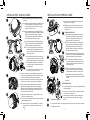
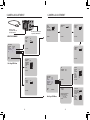
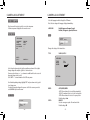
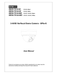
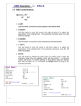
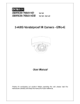
INSTRUCTION MANUAL Ultra Resolution Day & Night IR Dome Camera Ultra Resolution Day & Night IR Dome Camera P/N 01.BMS.11.0071401 V1.1 Vandal Model: DPV24DL Indoor Model: DPD24DL Please read this manual thoroughly before use and keep it handy for future reference. -i- -ii- INTRODUCTION Features All Models Feature: DPD24DL • 1/3” Sony Super HAD™ II CCD • Indoor Dome Model • 2.8-10.5mm Varifocal Day/Night Lens F1.4 DC Iris • Camera Mounting: Surface / Flush mounting • 600 TV lines of resolution • Advanced Digital Noise Reduction (DNR) DPV24DL • Shadow Reduction (ATR) • Smart IR technology • Vandal Dome Model • OSD menu control • Camera Mounting: Surface Mount • Privacy Masking / Motion Detection • VIDEO OUT(BNC) • Operates in 12VDC or 24VAC • Test Monitor Output (RCA) • 0 Lux with IR LED SPECIFICATIONS General Power source Power consumption Image sensor Total pixels Scanning system Scanning frequency Sync.system Resolution Min.illumination Video output S/N Ratio Power input Video output Lens mount Lens Operating temperature Operating humidity -iii- DPD24DL DPV24DL DC 12V / AC 24V +10% 3.0Watt Max 1/3” Sony Super HAD™ II CCD 811 (H) x 508 (V) 2:1 interlace 15.734KHz(H), 59.95Hz(V) Internal / Line Lock 600 TV Lines 0 Lux IR LED On 1.0 Vp-p (75 ohm, composite) more than 50dB (AGC OFF) 2-Pin terminal block (Detachable) BNC Connector (2nd video RCA) Fixed mount 2.8 - 10.5mm F1.4 Varifocal DC Auto iris -10~50°C 0-99% (non-condensing) -1- MEASUREMENTS PACKING CONTENTS 97.0 mm 3.82 in Indoor Dome package contains the following: 55.5 mm 2.19 in 112 mm 4.4 in 3/4’’ -14 NPS thread 40 mm 1.57 in 3.4" 87 mm Ø 0.1" 3.5 mm 5.1" 130 mm 3.9" 100.0 mm Vandal Dome Dimensions Base hole positions 100° 112 mm 4.4 in Camera in housing----------------------------------1 Camera Locking screw (PA3 Type)-------------1 Instruction guide (This Document)--------------1 Surface & Flush Mounting Templates----------2 RCA - BNC test cable-------------------------------1 Junction Box Plate-----------------------------------1 Mounting screw pack-------------------------------1 Vandal Dome package contains the following: Camera in housing----------------------------------1 Camera Locking screw (PM4 Type)-------------1 Instruction guide (This Document)--------------1 Surface Mounting Template-----------------------1 RCA - BNC test cable-------------------------------1 Junction Box Plate-----------------------------------1 Mounting screw pack-------------------------------1 Star shape dome cover Tamper key------------1 Conduit Key-------------------------------------------1 Locking Screw Conduit Key Star Shape Key Mounting Screws Pack. 3pc 70mm / 2.8in Screws 3pc 30mm / 1.2in Screws 3pc 40mm 1.6in plugs JUNCTION BOX PLATE 137° 123° Junction box plate allows fitting of either Vandal dome or Indoor dome to standard 2S, 4S and Octagon junction boxes. 5.1" 130 mm Junction Box fitting plate accessories: Indoor Dome Dimensions 27 mm 1.1 in Underside Base hole positions 88.9 mm 3.5 in 39 mm 1.5 in 115 mm 4.5 in Recess Mount Fitting dimensions Recess cutout and fitting clearance. -2- Junction Box Fiting plate --------------------------1 2S / 4S plate screws (KM3.5 Type)-------------4 Octagon fitting screws (KM4 Type)--------------2 Base Fitting Screws PWM3-----------------------3 7 mm .28 in 46.0 mm 1.8 in Base Fitting Screw. Octagon Screw 2S / 4S Screw Base Fitting Screws 83.3 mm 3.28 in Screw hole overview Vandal dome fitting illustration -3- Plate fitting flush side to the junction box JUNCTION BOX INSTALLATION TYPES Screws Cable Entry 2S Fitting VANDAL DOME FITTINGS a. 2S Fitting requires only 2pcs of base attachment screws. Note: You have a reduced space in which to hide cables using this type of installation. Recommended for indoor dome only. Note: All plate fittings are put so screw holes show the countersunk cutouts. Camera base mount fits into the Pendant Cap - model # MNTV2XPC Replaces the need for the camera base. Compatible with ceiling conduit installations Wall Mount - model # MNTV2XW a. 4S Fitting required 4pcs of base attachment screws. Screws Cable Entry Note: A 4S junction box provides the most robust fitting of a camera to a junction box. Suitable for both indoor and vandal domes. Junction Box Accessory - model # MNTV2XJ Fits either wall mount and corner mount bracket. Symmetrical so reversible for top or bottom conduit. 4S Fitting Pole Mount - model # MNTV2XP a. Octagon Box requires only 2pcs of base attachment screws. Screws Note Screws used for the octagon box are larger compared to those used for the 2S/4S (M4 type). Suitable for both indoor and vandal domes Cable Entry Corner Mount bracket - model # MNTV2XR Can fit either Wall Bracket or Junction Box. Octagon Box -4- -5- Pendant Mount - model # MNTV2XC INSTALLATION. VANDAL DOME a) Remove the three tamper screws using the Hex key provided. 1 1 b) Use included mounting template to mark and pre-drill the required holes. Use included 2.8” screws to mount the camera directly to the mounting surface. Proceed to step 4 b 2 INSTALLATION. INTERNAL DOME a or Remove the camera base by unscrewing the base locking screw (indicated with a padlock marking) and turn camera module approx. 5 degrees counter-clockwise to detach camera base from the camera module. Proceed to step 3 a) Press down on the tab marked with an arrow to lift up the dome cover slightly b) While pressing on tab, twist the dome cover anticlockwise to release dome cover from back clips. Lift off the cover. b a 2 3a a) Use the included surface mounting template or the base to mark and pre-drill all required holes. Attach camera base to mounting surface. 3 a NOTE: If you plan on installing onto a junction box, attach provided mounting plate first to the junction box and then attach camera base to the mounting plate. a) Reinsert camera module into camera base by ligning up the arrow notches, and turning camera module clockwise to lock into place. b 4 3 3b c b) Reinstall base locking screw as indicated by padlock mark to secure camera base to camera module. a) Remove camera cover by squeezing the back and front of the cover as indicated by the “PRESS” indicators at the same time and lifting it up and away from the lens. 4 b OR Remove the camera base by unscrewing the base locking screw (indicated with a padlock marking) and turn camera module approx. 5 degrees counter-clockwise to detach camera base from the camera module. a) Use the included surface mounting template or the base to mark and pre-drill all required holes. Attach camera base to mounting surface. NOTE: If you plan on installing onto a junction box, attach provided mounting plate first to the junction box and then attach camera base to the mounting plate. c) Reinstall base locking screw as indicated by padlock mark to secure camera base to camera module. Skip step 4 FLUSH MOUNT ONLY c) Adjust camera viewing angle and secure into place by tightening thumb screw using a flat head screwdriver. Make lens and OSD adjustments as required. NOTE lens adjustment levers are by default in the locked position, turn counter clockwise to unlock. a) Re-attach the camera cover, using the locking nut as a guide, until it snaps into place. a) Use included mounting template to mark and pre-drill the required holes. Use included 2.8” screws to mount the camera directly to the mounting surface. Proceed to step 5 b) Reinsert camera module into camera base by ligning up the arrow notches, and turning camera module clockwise to lock into place. Note: If you plan to use conduit fitting, remove conduit cap using the conduit key. b) Insert the included video test cable into the RCA jack and connect to test monitor to set up camera. (see page 8) 5 b SURFACE MOUNT ONLY a) Cut flush mounting hole into surface using provided flush mounting template. b) Insert dome into cutout and turn screwdriver clockwise to unlock the 3 mounting arms. c c) Continue turning clockwise to move mounting arms down until they make contact with inner mounting surface. b) Use the Hex key to tighten the tamper screws to create a proper weatherproof seal. 5 Follow step 4 on page 6. Note: Make sure dome cover cord attached to the camera module does not get caught in the rubber seal of dome. 6 a) Re-attach the camera cover, using the locking nut as a guide, until it snaps into place. -6- b) Reattach dome cover. -7- CAMERA ADJUSTMENT CAMERA ADJUSTMENT RCA Service Connector Use supplied RCA - BNC cable If you require BNC output. OSD function joystick. Pressing down on joystick acts as ENTER function. MENU TREE SUMMARY SETUP MENU LANGUAGE LENS WHITE BAL PICT ADJUST NR ENGLISH AUTO ATW NEXT EXIT SAVE ALL AUTO IRIS TYPE MODE SPEED DC AUTO ATW 239 SPEED DELAY CNT 016 ATW FRAME x1.00 ENVIRONMENT OUTDOOR MANUAL WB LEVEL RETURN RETURN 058 First Page OSD Menu 080 USER2 WB B-GAIN R-GAIN RETURN 000 128 128 128 150 ATR LUMINANCE CONTRAST Y/C 004 004 SETUP MENU BACKLIGHT OFF ATR OFF PRIVACY OFF MOTION DET OFF CAMERA ID OFF SYNC INT CAMERA RESET BACK EXIT SAVE ALL Next Page OSD Menu -8- 043 047 RETURN OFF RETURN NR NR MODE Y LEVEL C LEVEL 029 077 RETURN RETURN PICT ADJUST MIRROR BRIGHTNESS CONTRAST SHARPNESS HUE GAIN USER1 WB B-GAIN R-GAIN MID MID RETURN CAMERA ID CAMERA ABCDEFGHIJKLMNOPQRSTUV WXYZ0123456789-!#$%&’ ()_`.:;<=> @^*./^*X+/ CHR1 CHR2 CLR POS RETURN -9- PRIVACY AERA SEL TOP BOTTOM LEFT RIGHT COLOR TRANSP MOSAIC RETURN 1/4 1 1.00 OFF MOTION DET DETECT SENSE BLOCK DISP OFF MOTION AREA ON AREA SEL 1/4 TOP BOTTOM LEFT RIGHT RETURN 000 000 000 000 111 000 000 000 000 CAMERA ADJUSTMENT OSD MENU control CAMERA ADJUSTMENT Select the language in which to display the OSD menu. Note: Selection changes the language displayed immediatley. Press down on the function joystick to access the setup menu. • Main setup menu is displayed on the monitor screen. SETUP MENU LANGUAGE: English,Japanese,German, French Russian, Portuguese, Spanish, Chinese. LENS: SETUP MENU LANGUAGE LENS WHITE BAL PICT ADJUST NR ENGLISH AUTO ATW SETUP MENU LANGUAGE LENS WHITE BAL PICT ADJUST NR ENGLISH AUTO ATW Changes the settings of the internal lens.. NEXT EXIT SAVE ALL TYPE:MANUAL,AUTO NEXT EXIT AUTO IRIS TYPE MODE SPEED SAVE ALL Select a function by moving the joystick up and down and move left or right to change setting value and press joystick to confirm selection. If a menu option features a , a sub menu is available which can be accessed by pressing down on the joystick. Select ‘NEXT ’ to view remainder of the OSD setup menu Once finished updating settings, highlight ‘EXIT’ and press down on the joystick to exit setup menu. To retain the changed settings after a power on/off of the camera you need to select SAVE ALL option on the menu. LANGUAGE SETUP MENU LANGUAGE LENS WHITE BAL PICT ADJUST NR ENGLISH AUTO ATW -10NEXT EXIT SAVE ALL DC AUTO 080 RETURN MODE: SPEED: AUTO,CLOSE,OPEN -AUTO: The mechanical iris is controlled automatically -CLOSE: The mechanical iris is set to the closed position -OPEN: The mechanical iris is set to the open position Default setting is Auto 000-255 Sets the convergence speed of the mechanical iris. Default setting is 80 -11- CAMERA ADJUSTMENT CAMERA ADJUSTMENT WHITE BAL SETUP MENU LANGUAGE LENS WHITE BAL PICT ADJUST NR USER1 WB B-GAIN R-GAIN ENGLISH AUTO ATW White Balance can be set to following: NEXT EXIT ALL ATW / PUSH / SAVE USER1 / USER2 / ANTI CR / MANUAL / PUSH LOCK RETURN • USER2 • ATW 029 077 User defined gain adjustment on B and R USER2 WB B-GAIN R-GAIN ATW 239 SPEED DELAY CNT 016 ATW FRAME x1.00 ENVIRONMENT OUTDOOR 043 047 RETURN RETURN SPEED: DELAY CNT: ATW FRAME: ENVIRONMENT: 000-255 Specifies the AE control for ATW Default setting is 239 000-255 Sets the time based of ATW change. Default setting is 16 x0.50 / x1.00 / x1.50 / x2.00 Sets pull in frame for magnification Default setting is X1.00 INDOOR / OUTDOOR Set the pull in frame of ATW Default setting is OUTDOOR • PUSH Use white balance regardless of the subject conditions. • USER1 User defined gain adjustment on B and R -12- B-GAIN: R-GAIN: 000-255 B Gain adjustment for WB 000-255 R Gain adjustment for WB • ANTI CR • MANUAL ATW Activates color rolling suppression. MANUAL WB LEVEL 058 RETURN -13- CAMERA ADJUSTMENT CAMERA ADJUSTMENT LEVEL: 000-255 Specifies the R and B gain values for manual WB. The actual variable range is limited to the range from the low color temperature (approx. 1800K) to the high color temperature (approx. 10500K). Default setting is 58 • PUSH LOCK Press down on joystick to set current scene as the white balance level. Use a grey card in front of lens to give a nutural white level. PICT ADJUST SETUP MENU LANGUAGE LENS WHITE BAL PICT ADJUST NR NEXT SAVE ALL OFF 000 128 128 128 150 RETURN • • • • • • MIRROR: ON / OFF BRIGHTNESS:000-255 CONTRAST:000-255 SHARPNESS:000-255 HUE: 000-255 GAIN: 000-255 SETUP MENU LANGUAGE LENS WHITE BAL PICT ADJUST NR ENGLISH AUTO ATW Digital Noise Reduction. NEXT This function reduces the background noise in a low luminance environment. EXIT SAVE ALL NR MODE: Y LEVEL: C LEVEL: ENGLISH AUTO ATW Picture and display control settings EXIT PICT ADJUST MIRROR BRIGHTNESS CONTRAST SHARPNESS HUE GAIN NR NEXT “Y/C” / “OFF” / “Y” / “C” Noise reduction Filter mode. 000-015 Adjustment of the Y filter strength. Default setting is 4 000-015 Adjustment of the C filter strength. Default setting is 4 SETUP MENU LANGUAGE LENS WHITE BAL PICT ADJUST NR ENGLISH AUTO ATW NEXT EXIT SAVE ALL From the main setup menu select NEXT to enter second page of main setup menu. Horizontally flip the display output. Screen brightness. Screen contrast. Screen sharpness. Adjust the hue. Adjust the gain. -14- -15- CAMERA ADJUSTMENT SETUP MENU BACKLIGHT OFF ATR OFF PRIVACY OFF MOTION DET OFF CAMERA ID OFF SYNC INT CAMERA RESET BACK EXIT CAMERA ADJUSTMENT •LUMINANCE •CONTRAST PRIVACY OFF / ON Hide an area so that it is not displayed on the monitor. PRIVACY AERA SEL TOP BOTTOM LEFT RIGHT COLOR TRANSP MOSAIC RETURN SAVE ALL BACKLIGHT OFF / BLC / HLC -OFF Backlight compensation OFF -BLC Backlight compensation ON -HLC High light compensation ON SHADOW REDUCTION (ATR) OFF / ON This function compensates for darker areas surrounding the object to provide naturally sharp picture and improves contrast in bright/dark areas. ATR LUMINANCE CONTRAST MID MID RETURN -16- Sets the extent of the luminance compression (MID/HIGH/LOW) Sets the extent of the contrast enhancement (MID/MIDHIGH/HIGH/LOW/MIDLOW) 1/4 1 1.00 OFF 000 000 000 000 AREA SEL: Selects the mask frame to be adjusted. TOP: Sets the top side of the mask frame selected by the AREA SEL parameter BOTTOM: Sets the bottom side of the mask frame selected by the AREA SEL parameter. LEFT: Sets the left side of the mask frame selected by the AREA SEL parameter. RIGHT: Sets the right side of the mask frame selected by the AREA SEL parameter COLOR: TRANSP: MOSAIC: Sets the colors of the mask frames Sets the transparency ratio of the mask frames. Sets the mask frame mosaic to ON or OFF -17- CAMERA ADJUSTMENT MOTION DET CAMERA ADJUSTMENT OFF / ON Motion Detection is defined by rectangular areas. This give a visual identification of motion areas. MOTION DET DETECT SENSE BLOCK DISP OFF MOTION AREA ON AREA SEL 1/4 TOP BOTTOM LEFT RIGHT RETURN 111 000 000 000 000 BOTTOM: Set the bottom side of the monitoring frame selected by the AREA SEL parameter LEFT: Set the left side of the monitoring frame selected by the AREA SEL parameter. RIGHT: Sets the right side of the monitoring frame selected by the AREA SEL parameter CAMERA ID OFF / ON Camera ID shows a name on the screen as chosen. CAMERA ID CAMERA DETECT SENSE: Sets the motion detection sensitivity BLOCK DISP: ON/OFF/ENABLE status of the motion detection block display. ON: Make motion areas visible, OFF: Hide motion areas ENABLE Press enter to access the “dead band setting” screen, on-screen cursor moves in response to the inputs Left, Right, Up and Down to set the sensing area, or dead band for specified blocks. This allows you to specify and set an area of motion which is not rectangular in shape. Press and hold SET button 3 seconds to exit. MOTION AREA: ON / OFF Enable / Disable Area No. ABCDEFGHIJKLMNOPQRSTUV WXYZ0123456789-!#$%&’ ()_`.:;<=> @^*./^*X+/ CHR1 CHR2 CLR POS RETURN Use Up/Down/Left/Right to move around. CHR1/2 changes the selection fonts to alternative selection, CLR will clear info. POS allows position change. AREA SEL: 1/4 / 2/4 / 3/4 / 4/4. Selects motion area number. TOP: Set the top side of the monitoring frame selected by the AREA SEL parameter. -18- -19- CAMERA ADJUSTMENT TROUBLE SHOOTING Refer to the following table if you are experiencing trouble with your camera. Contact an authorized technician if the table does not provide you with a solution to the trouble. LL PHASE 326 Nothing appears on the screen. Check that the power cord and line connection between the camera and monitor are connected properly. Check that you have properly connected VIDEO cable to the camera VIDEO output jack. The image on the screen is dim. Is lens stained with dirt? Clean lens with soft, clean cloth. Adjust the monitor contrast & brightness controls Re-position the camera if necessary. The image on the screen is dark. RETURN Adjust the contrast feature of the monitor. If you have an intermediate device, set the 75Ω / Hi-z properly. The camera is not working properly, and the surface of the camera is hot. Check that you have properly connected the camera to an appropriate power source. IR LED's don't appear to be working (not glowing red in the dark) SYNC INT / LL Video synchronization displayed INT(Internal) or LL (Line Lock) Note: Shows INT with DC only model. And LL setting for camera model when connected to a AC supply. PHASE: 000-524 Adjust the phase in the vertical direction when the line lock mode is available. • CAMERA RESET This will reset all settings for all menus to manufacturer defaults. This allow you to return to shipped settings from the manufacturer. EXIT / SAVE ALL • EXIT • SAVE ALL Ensure that the power provided to the camera at the camera end meets the power consumption requirements as per the camera specifications. The Motion Detection function does not work. Check that MOTION DET in SETUP 2 menu is ‘ON’ for the selected area. Enable Block display ON will show a visual indication on the display output for the detected areas. Color is not correct. Check the setting of WHITE BAL SETUP menu. Under certain incandescent lighting,some color shifting may take place. This is normal due to sensitivity to IR light When the resistance value of copper wire is at [20˚C(68˚F)] Copper wire size (AWG) Resistance (Ω/m) Voltage Drop (V/m) #24(0.22mm2) 0.078 0.028 #22(0.33mm2) 0.050 0.018 #20(0.52mm2) 0.030 0.011 As shown in the table above, voltage decreases as the wire gets longer. Therefore use of an excessively long adaptor output line for connection to the camera may affect the performance of the camera. *Standard voltage for camera operation : AC 24V ±10% or DC 12V ±10% *There may be some deviation in voltage drop depending on the type of wire and the manufacturer. Notes Exit OSD menu. Saves the settings to camera -20- #18(0.83mm2) 0.018 0.006 • Be sure to connect power only after all the installation is complete. • Use the UL listed, CLASS 2 power transformer for AC24v adaptor. -21-