1
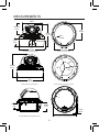
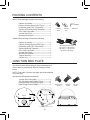
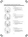
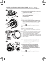
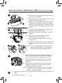
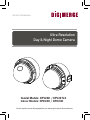
INSTRUCTION MANUAL Ultra Resolution Day & Night Dome Camera Vandal Models: DPV24D / DPV24TLX Indoor Models: DPD23D / DPD24D Please read this manual thoroughly before use and keep it handy for future reference. INTRODUCTION Features All Models Feature: DPD24D • • • • • • • • • • • • Indoor Dome Model • 2.8-10.5mm Varifocal Day/Night Lens F1.4 DC Iris 1/3” Sony Super HAD™ II CCD Excellent low light performance using Polaris Vision 2 technology. 0.15 Lux / F1.2 (Color) 0.001 Lux w/Sense-Up at x256 600 TV lines(Color) of resolution 3D Digital Noise Reduction (3D-DNR) OSD menu control Privacy Masking / Motion Detection VIDEO OUT(BNC) Operates in 12VDC or 24VAC Test Monitor Output Camera Mounting: Surface / Flush mounting (Indoor Model only) DPV24D • Vandal Resistant Dome Model • 2.8-10.5mm Varifocal Day/Night Lens F1.4 DC Iris DPV24TLX • • • • • • DPD23D • Indoor Dome Model • 3.6mm Fixed Lens Vandal Resistant Dome Model 2.8-10.5mm Varifocal Day/Night Lens F1.4 DC Iris Smart IR technology ICR filter to give clear night vision ArcticPro technology with built-in heater 0 Lux with IR LED SPECIFICATIONS General Power source Power consumption Image sensor Total pixels Scanning system Scanning frequency Sync.system Resolution Min.Illumination Video output S/N Ratio Operating Temperature Power input Video output Lens mount Lens Operating humidity DPD23D DPD24D DPV24D DC 12V / AC 24V +10% DPV24TLX 10 Watts (Heater On) 1/3” Sony Super HAD™ II CCD 811 (H) x 508 (V) 2:1 interlace 15.734KHz(H), 59.95Hz(V) Internal / Line Lock 600 TV Lines 0.15Lux / 0.001Lux 0 Lux IR LED On Sense Up at x256 1.0 Vp-p (75 ohm, composite) more than 50dB (AGC OFF) -10°C - +50°C -40°C - +50°C 2-Pin terminal block (Detachable) BNC Connector (2nd video RCA) Fixed mount 3.6mm Fixed 2.8 - 10.5mm F1.4 Varifocal DC Auto iris 0-90% (non-condensing) 2.5 Watts -1- MEASUREMENTS 97.0 mm 3.82 in 55.5 mm 2.19 in 112 mm 4.4 in 3/4’’ -14 NPS thread 40 mm 1.57 in 3.4" 87 mm Ø 0.1" 3.5 mm 5.1" 130 mm 3.9" 100.0 mm Vandal Dome Dimensions Base hole positions 100° 112 mm 4.4 in 137° 123° 5.1" 130 mm Indoor Dome Dimensions 27 mm 1.1 in Underside Base hole positions 39 mm 1.5 in 115 mm 4.5 in Recess Mount Fitting dimensions Recess cutout and fitting clearance. -2- 7 mm .28 in PACKING CONTENTS Indoor Dome package contains the following: Camera in housing----------------------------------1 Camera Locking screws (PA3 Type)------------2 Instruction guide (This Document)--------------1 Surface & Flush Mounting Templates----------2 RCA - BNC test cable-------------------------------1 Junction Box Plate-----------------------------------1 Mounting screw pack-------------------------------1 Vandal Dome package contains the following: Camera in housing----------------------------------1 Camera Locking screws (PM4 Type)-----------3 Instruction guide (This Document)--------------1 Surface Mounting Template-----------------------1 RCA - BNC test cable-------------------------------1 Junction Box Plate-----------------------------------1 Mounting screw pack-------------------------------1 Tamper allen key-------------------------------------1 Conduit Key-------------------------------------------1 Locking Screw Conduit Key Allen Key Mounting Screws Pack. 3pc 70mm / 2.8in Screws 3pc 30mm / 1.2in Screws 3pc 40mm 1.6in plugs JUNCTION BOX PLATE Junction box plate allows fitting of either Vandal dome or Indoor dome to standard 2S, 4S and Octagon junction boxes. NOTE: Flush side of junction box plate should be attached to junction box Junction Box fitting plate accessories: Junction Box Fitting plate -------------------------1 2S / 4S plate screws (KM3.5 Type)-------------4 Octagon fitting screws (KM4 Type)--------------2 Base Fitting Screws PWM3-----------------------3 88.9 mm 3.5 in 46.0 mm 1.8 in Base Fitting Screw. Octagon Screw 2S / 4S Screw Base Fitting Screws 83.3 mm 3.28 in Screw hole overview Vandal dome fitting illustration -3- Junction box fitting plate attached to camera JUNCTION BOX INSTALLATION TYPES 2S FITTING a. 2S Fitting requires only 2pcs of base attachment screws. Screws Cable Entry Note: You have a reduced space in which to hide cables using this type of installation. Recommended for indoor dome only. 4S FITTING a. 4S Fitting requires 2pcs of base attachment screws. Screws Cable Entry Note: Screws used for the 4S box are larger compared to those used for the 2S (M4 type). Suitable for both indoor and vandal domes TWO GANG FITTING a. Two gang fitting (switch box) requires 4pcs of base attachment screws. Screws Note: A two gang provides the most robust fitting. Suitable for both indoor and vandal domes. Cable Entry OCTAGON FITTING a. 4” Octagon fitting requires only 2pcs of base attachment screws. Screws Cable Entry Note Screws used for the octagon fitting are larger compared to those used for the 2S/4S (M4 type). Suitable for both indoor and vandal domes -4- VANDAL DOME FITTINGS Pendant Cap - model # MNTV2XPC Replaces the need for the camera base. Compatible with ceiling conduit installations Junction Box Accessory - model # MNTV2XJ Fits either wall mount and corner mount bracket. Symmetrical so reversible for top or bottom conduit. Corner Mount bracket - model # MNTV2XR Can fit either Wall Bracket or Junction Box. -5- Wall Mount - model # MNTV2XW Pole Mount - model # MNTV2XP Pendant Mount - model # MNTV2XC INSTALLATION. VANDAL DOME 1 DPV24TLX ONLY When using DC power, note the correct polarity stated on the label attached to the power cord. 1) Remove the three tamper screws using the provided allen key. Size is standard T-15 Note: If you plan to use conduit fitting, remove conduit cap using the prodivded conduit key. Method 1 - Direct Attach Install 2 2a) Use included mounting template to mark and predrill the required holes. Use 2pc of the 2.8” screws to mount the camera directly to the mounting surface. a Remove (one base locking screw, used for shipping purposes) and install the 3rd 2.8” screw. Go to step 4 on page 7 to complete installation. OR Method 2 - Camera Base Install Note: Use this method if installing onto junction box plate. 2b) Remove the camera base by unscrewing the base locking screw, and turn camera module approx. 5 degrees counter-clockwise to detach camera base from the camera module. Now you install the base to the correct holes as indicated on the mount template using the 1.2” screws. b 3 Note: If you plan on installing onto a junction box, attach provided fitting plate first to the junction box and then you attach the camera base to the fitting plate. a b 3a) Reinsert camera module into camera base by ligning up the arrow notches, and turning camera module clockwise to lock into place. 3b) Use the supplied three base locking screws to secure camera base to camera module. Go to step -6- 4 on page 7 to complete installation. ed on the INSTALLATION. VANDAL DOME 4 4) Remove camera cover by squeezing the back and front of the cover as indicated by the “PRESS” indicators at the same time and lifting it up and away from the lens. provided e conduit nd prescrews ng 5 pping 5) Insert the included video test cable into the RCA jack and connect to a test monitor to set up camera. tion. on box he base prox. 5 era base he base unt 6 6a) Adjust camera viewing angle and secure into place by tightening thumb screw using a flat head screwdriver. 6b) Adjust lens and OSD as required. 6c) Re-attach the camera cover, using the thumb screw as a guide, until it snaps into place. Note: Lens adjustment levers are by default in the locked position. Turn counter clockwise to unlock. Tighten levers to secure lens setting. 7 7a) Re-attach the camera cover. Line up arrows as shown in figure 3a on page 6 as a guide 7b) Use the allen key to tighten the tamper screws to create a proper weatherproof seal. Note: Make sure dome cover cord does not get caught in the rubber seal. -7- INSTALLATION. INDOOR DOME (Surface Fitting) 1 1a) Press down on the tab marked with an arrow to lift up the dome cover slightly b a 1b) While pressing on tab, twist the dome cover counter clockwise just a few degrees to release dome cover from back clips. Lift off the cover. Method 1 - Direct Attach Install 2 2a) Use included mounting template to mark and predrill the required holes. Use included 2.8” screws to mount the camera directly to the mounting surface. a Go to step 3 on page 9 to complete installation. OR Method 2 - Camera Base Install Note: Use this method if installing onto junction box plate. 2b) Remove the camera base by unscrewing the base locking screws (indicated by padlock markings) and turn camera module approx. 5 degrees counter-clockwise to detach camera base from the camera module. Install the base as indicated using the 1.2” screws. b 3 Note: If you plan on installing onto a junction box, attach provided mounting plate first to the junction box and then attach camera base to the mounting plate. a b 3a) Reinsert camera module into camera base by ligning up the arrow notches, and turning camera module clockwise to lock into place. 3b) Reinstall the base locking screws. (indicated by padlock markings) Go to step -8- 3 on page 9 to complete installation. ow to lift INSTALLATION. INDOOR DOME (Semi-Flush Fitting) 1 1a) Press down on the tab marked with an arrow to lift up the dome cover slightly r ease nd prescrews ng 1b) While pressing on tab, twist the dome cover counterclockwise to release dome cover b a 2 a) Cut semi flush mounting hole into surface using provided flush mounting template. Note: Always cut according to the inside of the cutout template tion. b) Insert dome into cutout. Make sure that the mounting arms are not extended. b c) Turn screwdriver clockwise to unlock all of the 3 mounting arms. on box he base ings) s from the ed using 1c) Remove the camera base by unscrewing the base locking screws (indicated by a padlock markings) and turn camera module approx. 5 degrees counterclockwise to detach camera base from the camera module. c 3 d) Continue turning clockwise to move mounting arms down until they make contact with inner mounting surface. d Note: Once mounting arms have made contact with the inner mounting surface, do not apply too much pressure to avoid damaging surface. a) Remove camera cover by squeezing the back and front of the cover as indicated by the “PRESS” indicators at the same time and lifting it up and away from the lens. b) Insert the included video test cable into the RCA jack and connect to a test monitor to set up camera. (see page 10) c) Adjust camera viewing angle and secure into place by tightening thumb screw using a flat head screwdriver. Adjust lens and OSD as required. 4 Note: Lens adjustment levers are by default in the locked position. Turn counter clockwise to unlock. Tighten levers to secure lens setting. a) Re-attach the camera cover, using the thumb screw as a guide, until it snaps into place. b) Reattach dome cover. -9- CAMERA ADJUSTMENT Menu Setup RCA Service Connector Use supplied RCA - BNC cable If you require BNC output. OSD function joystick. Pressing down on joystick acts as ENTER function. MENU TREE SUMMARY LENS • DC or MANUAL (Model DPD23D) EXPOSURE • SHUTTER • AGC • SENS-UP • BLC • D-WDR • RETURN WHITE BAL • AWB • ATW • AWC SET • OUTDOOR • INDOOR • MANUAL DAY / NIGHT • AUTO • COLOR • B/W 3DNR • OFF • ON SPECIAL • CAM TITLE • D-EFFECT • MOTION • PRIVACY • SYNC • LANGUAGE ADJUST • SHARPNESS • MONITOR • OSD COLOR RESET • FACTORY • RETURN 1. Press down on the function joystick to access the setup menu. • Main setup menu is displayed on the monitor screen. 1. 2. 3. 4. 5. 6. 7. 8. 9. LENS LENSDC EXPOSURE WHITE BAL DAY NIGHT 3DNR SPECIAL ADJUST RESET EXIT DC ATW AUTO OFF 2. Select a function by moving the joystick up and down and move left or right to change setting value and press joystick to confirm selection. 3. If a menu option features a ' ', a sub menu is available which can be accessed by pressing down on the joystick 4. Once finished updating settings, highlight 'EXIT' and press down on the joystick to exit setup menu -10- CAMERA ADJUSTMENT LENS Using this function, you can control screen brightness. 1. Highlight 'LENS' in the main setup menu 2. Press the joystick to access the DC lens setup menu. 3. After completing setting update, highlight 'RETURN' to save setting and return to previous menu essing down function. e essing SETUP 1. LENS 2. EXPOSURE DC • NOTE The brightness level can be adjusted within the range of 0 - 100. Default setting - 50 LENS BRIGHTNESS -----|----�� RETURN RET With Model DPD23D DC Lens setting is MANUAL EXPOSURE SETUP 1. LENS 2. EXPOSURE 3. WHITE BAL DC MANUAL The EXPOSURE menu is used to set the automatic light control method for the camera. 1. Highlight 'EXPOSURE' in the main setup menu 2. Press the joystick to access the exposure setup menu. EXPOSURE SHUTTER AGC SENSE-UP BLC D-WDR RETURN SHUTTER : Select the shutter mode. (1/60, FLK - 1/100,000 sec, x2 - 256) Default setting is 1/60 AGC: Auto gain control (LOW / MIDDLE / HIGH) Default setting is MIDDLE -11- �/�� MIDDLE AUTO OFF OFF RET CAMERA ADJUSTMENT SENSE-UP B EXPOSURE SHUTTER AGC SENSE-UP BLC D-WDR RETURN The 1/60 MIDDLE AUTO OFF OFF RET Select digital slow shutter speed setting in order to allow extra light into the camera thereby providing higher sensitivity in low light conditions. NOTE only adjustable if SHUTTER setting is set to 'AUTO' or '1/60' - OFF : Deactivates the SENS-UP function. - AUTO : Activates SENS-UP function. Enter submenu to select maximum low shutter value SENSE-UP SENSE-UP RETURN x� RET Selectable low shutter values are as follows: x2 x4 x8 x16 x32 x64 x128 x 256 (default - x8) For proper setup, check setting during low light / night time conditions. Notes • It's recommended to keep the value in the x2 to x64 range to limit ghosting effect. -12- 1. H 2. P m ue CAMERA ADJUSTMENT BACKLIGHT (BLC) The BLC menu is used to adjust backlight compensation function to sharpen subjects in backlight situations 1. Highlight 'BLC' in the exposure setup menu. 2. Press the joystick to access the BLC setup menu. EXPOSURE SHUTTER AGC SENSE-UP BLC D-WDR RETURN BLC (Backlight Compensation): Enter the BLC submenu to select an area in the scene which requires enhancing. Change the GAIN value (LOW/MIDDLE/HIGH) to set level of enhancement. BLC 1/60 MIDDLE AUTO OFF OFF RET BLC GAIN AREA DEFAULT RETURN LOW RET OFF HSBLC (Highlight Compensation): If a scene contains very bright light sources (e.g. car headlights),they will be masked to provide greater detail in the rest of the scene. Enter the HSBLC submenu to select an area in the scene which requires masking. Change the LEVEL value to set level of masking and change MODE to set whether to mask all day long or during low light conditions only. Default setting is OFF -13- CAMERA ADJUSTMENT Wide Dynamic Range (E-WDR) D-WDR : The D-WDR menu is used to adjust dynamic range of the camera electronically. This is especially useful in high contrast scenes in order to brighten up darker parts of the scene. 1. Highlight 'D-WDR' in the exposure setup menu. 2. Move the the joystick left/right to change setting to OFF/INDOOR/OUTDOOR. Default setting is OFF EXPOSURE SHUTTER AGC SENSE-UP BLC D-WDR RETURN 1/60 MIDDLE AUTO OFF OFF RET INDOOR : Preferred setting when camera is installed indoors. Default settings are LOW-6 and HIGH-9 OUTDOOR:: Preferred setting when camera is installed outdoors. Default settings are LOW-11 and HIGH-11 D-WDR LOW-LEVEL HIGH-LEVEL RETURN INDOOR ----|---- � ----|---- � RET White Balance (White Bal.) White balance function adjusts displayed colors to account for different lighting temperatures. 1. Highlight 'WHITE BAL' in the main setup menu. 2. Move the the joystick left/right to change setting to: AWB/AWC->SET/MANUAL/INDOOR/OUTDOOR/ ATW Default setting is AWB (Auto White Balance) -14- CAMERA ADJUSTMENT SETUP 1. LENS 2. EXPOSURE 3. WHITE BAL 4. DAY NIGHT ronically. peratures. DC AWB AUTO AWB(Automatic White Balance) : This mode automatically adjusts white balance AWC-SET : To obtain the optimum state under the current luminance levels, direct the camera to point toward a sheet of white paper and press the SET button. If the environment changes, including the light source, the white balance will require re-adjustment. MANUAL : The manual adjustment setting enables WHITE BAL MANUAL detailed color adjustment. Select 'ATW' or 'AWB' first BLUE ----|---- �� then change to 'MANUAL' adjustment setting and press RED --|----- �� RETURN RET the joystick. Set the appropriate color temperature by increasing / decreasing the red and blue color values and monitor the color changes of the object. Default settings are BLUE-41, RED-45 INDOOR : Select this when the color temperature is between 4,500˚K and 8,500˚K. OUTDOOR : Select this when the color temperature is between 1,800˚K and 10,500˚K. (sodium light) ATW(Auto Tracking White Balance) : This mode can be used within the color temperature range 1,800˚K ~ 10,500˚K Notes • White Balance may not work properly under the following conditions. In this case select the AWC mode. 1 When the color temperature of the environment surrounding the subject is outside of the supported temperature range (e.g. clear sky or sunset). 2 When the ambient illumination of the subject is dim. 3 If the camera is directed towards a fluorescent light or is installed in a place where illumination changes dramatically, the White Balance function may become unstable. -15- CAMERA ADJUSTMENT DAY/NIGHT The DAY/NIGHT menu is used to configure the day and night related settings for the camera. 1. Highlight 'DAY&NIGHT' in the main setup menu 2. Move the the joystick left/right to change setting to AUTO/COLOR/ B/W 3. Press the joystick to access the submenu's for AUTO and B/W settings SETUP 1. LENS 2. EXPOSURE 3. WHITE BAL 4. DAY NIGHT DC MANUAL AUTO COLOR : The picture is always displayed in color. B/W : The picture is always displayed in black and white. Press joystick to turn ON or OFF the burst signal in B/W mode. AUTO : The mode is switched to ‘Color ’ in a normal environment, but switches to ‘B/W’ mode when ambient illumination is low. To set up the switching time or speed for AUTO mode, press the joystick. You can now set the Delay in seconds for the Day - Night and the Night - Day transitions. -16- DAY NIGHT B/W BURST OFF RETURN RET DAY NIGHT AUTO DELAY -|----- � D-N (AGC) ---|--- ��� N-D (AGC) ---|-- �� RETURN RET he camera. CAMERA ADJUSTMENT Digital Noise Reduction (3D DNR) This function reduces the background noise in a low luminance environment. 1.Highlight '3DNR' in the main setup menu. SETUP 1. LENS 2. EXPOSURE 3. WHITE BAL 4. DAY NIGHT 5. 3DNR DC MANUAL AUTO ON 2. Move the the joystick left/right to change setting to OFF/ON OFF - Noise is not reduced ON - Noise is reduced 3. Press the joystick to access the submenu for ON setting. In the 3DNR submenu you can adjust the noise reduction level values range from 0 to 100. Default setting is 60. �DNR LEVEL RETURN -----|---- �� RET Notes • Noise levels can be very subtle, and may not be always noticable on adjusting • When adjusting the noise reduction level in 3DNR submenu, remember that the higher the level set, the more the noise level will be reduced, however this can have a softening effect on the image. -17- CAMERA ADJUSTMENT SPECIAL. 1. Highlight 'SPECIAL' in the main setup menu. • SETUP 1. LENS 2. EXPOSURE 3. WHITE BAL 4. DAY NIGHT 5. 3DNR 6. SPECIAL 7. ADJUST 8. RESET 9. EXIT DC • • ATW AUTO ON 2. Press the joystick to access the submenu for SPECIAL settings. SPECIAL 1. 2. 4. 5. 6. 7. 8. 9. CAM TITLE D-EFFECT MOTION PRIVACY SYNC LANGUAGE DEFECT RETURN OFF OFF OFF INT ENG RET • CAM TITLE : If you enter a title, the title will appear on the monitor. 1. Move the the joystick left/right to change setting to OFF/ON OFF - No camera title is displayed ON - Camera title is displayed -18- CAMERA ADJUSTMENT Notes • When the CAM TITLE is OFF no title will be displayed on the monitor even if you had previously setup a name. This is the master display setting. • Only English is available in this mode for camera title. • Only max 15 characters for the title allowed. 2. Press the joystick to access the submenu for ON setting. Here you will be able to enter the camera title. CAM TITLE 0123456789 ABCDEFGHIJK LMNOPQRSTUV WXYZ() ¯-_/■=&:~,. CLR POS END 3. Move the the joystick left/right/up/down to select a letter/number/symbol and press joystick to confirm selection. Repeat steps until camera title is completed and select 'POS' to select on-screen location for title and 'END' to save title. You can enter up to a maximum of 15 characters. Notes • If you move th e cursor to CLR and press the joystick , all the letters are deleted. To edit a letter, change the cursor to the bottom left arrow and press the joystick. Move the cursor over the letter to be edited, move the cursor to the letter to be inserted and then press the joystick. -19- CAMERA ADJUSTMENT D-EFFECT: Applies digital effects to camera image. 1. Highlight 'D-EFFECT' in the SPECIAL setup menu. SPECIAL 1. CAM TITLE 2. D-EFFECT 3. MOTION 4. PRIVACY 6. SYNC 7.access LANGUAGE 2. Press the joystick to the submenu. 8. RETURN OFF OFF OFF INT ENGLISH END D-EFFECT Notes FREEZE MIRROR D-ZOOM NEG.IMAGE RETURN OFF OFF OFF OFF RET 3. FREEZE: Freezes current image displayed 4. MIRROR: MIRROR will mirror the image. V-FLIP, will flip the image vertically. ROTATE, will vertically flip and also mirror. OFF, no image effect applied. 5. D-ZOOM: Allows digital zoom and position to be set. D-ZOOM D-ZOOM PAN TILT RETURN x 1.0 ----|-------|---RET 0 0 Digital Zoom can range from 1x to 32x. Too much digital zoom will result in blocky image Pan / Tilt range is -100 to 100. -20- ky image CAMERA ADJUSTMENT MOTION: You can monitor activity more efficiently, because a signal is generated by the camera whenever motion is detected. Visual notification is also available. 1. Highlight 'MOTION' in the SPECIAL setup menu SPECIAL 1. CAM TITLE OFF 2. D-EFFECT 4. MOTION OFF 5. PRIVACY OFF 6. SYNC INT 7. LANGUAGE ENG 8. DEFECT 9. RETURN RET 2. Move the the joystick left/right to change setting to OFF/ON 3. Press the joystick to access the submenu for ON setting MOTION AREA SELECT AREA DISPLAY SENSITIVITY MOTION VIEW RETURN AREA� ON -------|- �� OFF RET POSITION MOTION - AREA SELECT: - AREA DISPLAY: - SENSITIVITY: - MOTION VIEW: Select motion detection area number. AREA 1-4 With the area slected will be shown flashing on and off visually. Turns selected motion detection area ON or OFF. Pressing joystick when ON will change display to set the position and the size of the area. Moving the joystick will change the setting, and press joystick to accept. After you have set both position,size you can RET or AGAIN Adjust sensitivity for selected motion detection area (0-40). Turn motion detection view ON or OFF. When turned on, upon detection of motion, motion is shown as green dots to indicate area in which motion is taking place. Notes • Motion detection is normally part of a DVR which would provide more flexible customization options. -21- CAMERA ADJUSTMENT PRIVACY: Hide an area so that it is not displayed on the monitor. 1. Highlight 'PRIVACY' in the SPECIAL setup menu. 2. Move the the joystick left/right to change setting to OFF/ON 3. Press the joystick to access the submenu for ON setting - AREA SELECT: - AREA DISPLAY: - COLOR: PRIVACY AREA SELECT AREA� AREA DISPLAY ON COLOR -------|- � RETURN RET Select privacy area number. AREA 1-8 With the area slected will be shown flashing on and off visually. Turns selected privacy area ON or OFF. Pressing joystick when ON will change display to set the position and the size of the area. Moving the joystick will change the setting, and press joystick to accept. After you have set both position,size you can RET or AGAIN Range 0-15. Sets the color of the selected privacy area. LANGUAGE: The OSD supports English ,Korean,Japanese, Chinese, Simplified Chinese,Russian DEFECT: For Service use only! ADJUST ADJUST: SHARPNESS: Image edge sharpness 0 (soft image) to 31 oversharp (default is 12) MONITOR: CRT/LCD/USER setting for monitor type Note: For direct monitor connection only. (default is CRT) OSD COLOR: 0-15 color for OSD menu text (default is 3) RESET RESET: This will reset all settings for all menus to manufacturer defaults. This allow you to return to shipped settings from the manufacturer. -22- ADJUST SHARPNESS MONITOR OSD COLOR RETURN -|------- �� CRT � RET RESET FACTORY RETURN RESET RET REA� ON -|- � ly. IN an ------ �� RT ET SET RET TROUBLE SHOOTING Refer to the following table if you are experiencing trouble with your camera. Contact an authorized technician if the table does not provide you with a solution to the trouble. Nothing appears on the screen. Check that the power cord and line connection between the camera and monitor are connected properly. Check that you have properly connected VIDEO cable to the camera VIDEO output jack. The image on the screen is dim. Is lens stained with dirt? Clean lens with soft, clean cloth. Adjust the monitor contrast & brightness controls Re-position the camera if necessary. The image on the screen is dark. Adjust the contrast feature of the monitor. If you have an intermediate device, set the 75Ω / Hi-z properly. The camera is not working properly, and the surface of the camera is hot. Check that you have properly connected the camera to an appropriate power source. The Motion Detection function does not work. Check that MOTION is turned to ON in SPECIAL submenu. Color is not correct. Check the setting of WHITE BAL SETUP menu . When the resistance value of copper wire is at [20˚C(68˚F)] Copper wire size (AWG) Resistance (Ω/m) Voltage Drop (V/m) #24(0.22mm2) 0.078 0.028 #22(0.33mm2) 0.050 0.018 #20(0.52mm2) 0.030 0.011 #18(0.83mm2) 0.018 0.006 As shown in the table above, voltage decreases as the wire gets longer. Therefore use of an excessively long adaptor output line for connection to the camera may affect the performance of the camera. *Standard voltage for camera operation : AC 24V ±10% or DC 12V ±10% *There may be some deviation in voltage drop depending on the type of wire and the manufacturer. Notes • Be sure to connect power only after all the installation is complete. • Use only UL listed Class 2 AC 24V power transformer. -23- Ultra Resolution Day & Night Dome Camera P/N 01.BSM.11.0070201C V3.01