1
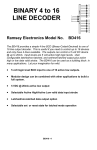
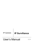
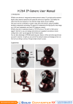
16CH H.264 Network Video Recorder User’s Manual IP surveillance 2012 OCT V1.1 NVR User Manual Notice WARNING Do not expose the DVR under the sunlight, heat or wet environment while installation. As it could decrease the performance of DVR and damage the machine. Do not touch the power plug or case with wet hands as this could result electric shock. Do not forcedly bend or put heavy object on power cable as this could result in injury to personal or equipment. Do not operate with damaged power cord or loose electrical outlet as this could result in electric shock or accident. Please use individual power instead of share electrical outlets with other electrical equipment as this could result in damage or accident. Do not attempt to service this DVR by yourself as it may expose you to dangerous voltage or other hazards. Please refer all service to the qualified servicing distributor. Please do not remove the machine housing during operation. It may cause electric shock or accidental injury. CAUTION Do not place the machine on an uneven surface or it would decrease the DVR efficiency or malfunction. Avoid any shock or bumping of the DVR while recording. Improper handling could damage the system. CAUTION Make sure the voltage selector switch is set to appropriate setting before plug in! ii NVR User Manual Table of Contents 1. Specifications ....................................................................................................... 1 2. Preparation ........................................................................................................... 2 2.1 Front Panel............................................................................................. 2 2.2 Installation .............................................................................................. 3 2.3 NVR Framework Diagram ...................................................................... 5 2.4 IPCAM & NVR Connection Settings ....................................................... 6 2.5 Remote Controller .................................................................................. 9 2.6 Mouse .................................................................................................. 10 2.7 Live View .............................................................................................. 11 3. Operations .......................................................................................................... 13 3.1 Turn On the NVR.................................................................................. 13 3.2 Main Menu ........................................................................................... 13 3.3 System Setup ....................................................................................... 14 3.4 Camera Setup ...................................................................................... 15 3.5 Alarm Setup ......................................................................................... 15 3.6 Record Operation ................................................................................. 19 3.7 Playback .............................................................................................. 20 3.8 Backup ................................................................................................. 21 3.9 Audio Setup.......................................................................................... 22 3.10 PTZ Setup ............................................................................................ 22 3.11 User Setup ........................................................................................... 24 3.12 User Shift ............................................................................................. 25 3.13 Night View Setup .................................................................................. 25 3.14 Turn Off the NVR.................................................................................. 26 3.15 The Status of HDD ............................................................................... 26 4. IE Connection ..................................................................................................... 27 5. NVR Networking Example ................................................................................. 29 iii NVR User Manual 1. Type Specifications 16CH NVR ( HD1080p ) SOC Hi3520 Video Input Video Output Support IP CAM x 16PCS CVBS (BNC) / VGA / Digital Output Audio Input / Output Display Resolution Alarm Input / Output 16CH NVR ( HD720p ) 1ch Input / 1ch Output 1080P ( 1920x1080 ) 720P (1280x720) 4CH Alarm In / 1 CH Alarm Out Compression Algorithm H.264 Video Format NTSC / PAL VGA (800X600 / 1280X1024 ) Display Resolution Digital Output (1920 x 1080) YPbPr Output(1920 x 1080) 200 / 240fps 1080P Performances record,and 1CH 1080P 400 / 480fps 720P record,and 4CH 720P playback playback Record Resolution CIF/1080P CIF/720P Motion Detection Video Motion Record Mode HDD Time/Sensor/Motion SATA 3.5”HDD (Max 2TB) x 4 pcs (No HDD Included) P/T/Z Control Network Resolution Network Protocol RS-485 CIF / 1080P CIF / 720P DHCP,DDNS,UPNP,SMTP,FAB Browser Internet Explorer (Windows) CMS WINDOWS / iMac 3G Mobile OS Windows Mobile, iPhone, Android, Symbian, Blackberry Control Mode Remote Control / USB Mouse / Internet USB USB x 2PCS Power ATX 150W AC 115V~230V Dimensions 419mm (W) x 392.6mm (D) x97mm (H) Net Weight 4.5kg (HDD Not Included) 1 NVR User Manual 2. Preparation 2.1 Front Panel 1. 0(+10)~9: Channel 1~16 2. POWER: Power on / Power off 3. MENU: Main Menu 4. ESC: Exit Menu 5. : 4 / 16 channel split screen display. 6. : Left / Fast Rewind 7. : Up / Channel add 8. : Down / Channel subtract 9. : Right / Fast Forward 10. ENTER: Confirm the setup 11. POWER: Power Indicator LED 12. HDD: HDD Indicator LED 13. LOCK: Keyboard Lock Indicator LED 14. ALARM: Alarm Indicator LED 15. IR: IR Indicator LED 16. IR Receiver 17. : Manual Record 18. : Play / Pause 19. ■: Stop 20. USB 2.0 Port: Connect to USB device to upgrade, backup; connect to USB mouse. 2 NVR User Manual 2.2 Installation 1. CVBS (BNC) Video Output 2. Audio Out 3. LAN Port 4. USB Port: Connect to USB device to upgrade, backup; connect to USB mouse. 5. XGA Output 6. YPbPr Output 7. Audio In 8. Digital Output 9. RS-485 / ALARM / IR Extending / GND 10. Power: ATX 150W AC 115V~230V 11. GND 3 NVR User Manual Alarm interface 4 channel alarm in 1 channel alarm output The above picture shows a typical alarm in /out connection way. In order to make the NVR work well, it must connect to the ground as the above picture. 4 NVR User Manual 2.3 NVR Framework Diagram 5 NVR User Manual 2.4 IPCAM & NVR Connection Settings Step 1: IPCAM connected to PC via net cable Step 2: PC set to a fixed IP PC IP could be set as 192.168.98.101, subnet mask 255.255.255.0, default gateway 192.168.98.1 6 NVR User Manual Step3: IpcamSearcher 1. Copy IpcamSearcher application in the CD to PC than execute. 2. Press Search botton than you can find the connected IP-CAM. Press Update to set the IP-CAM to the same LAN segment of PC. Step4: Set IP Address The IP of IPCAM could be set in Camera setting menu in NVR. 7 NVR User Manual Step5: Check the IP of NVR and IPCAM in the same network? Log in Network setting menu of NVR via network remote client to check the IP of NVR and IPCAM in the same network segment. When setting alarm information, the network segment of Router, IPCAM and NVR must be the same. NVR and IPsearcher software could not be connected to IPCAM at the same time. 8 NVR User Manual 2.5 Remote Controller Stop Record Lock Play Step/Pause Fast Rewind Slow Forward Fast Forward PTZ Iris Zoom in/out PTZ Setup PTZ Focus Search Mute Auto Switch Remote control ID setting key. Information Up Selection Left Selection Enter Right Selection Cancel MENU Down Selection 9 Display 16 Display Quad Display Number 1-9, Channel 1-16(Switchable) Inspection of remote controller ˇ Check the battery’s positive and negative polarity ˇ Check the battery’s power ˇ Make sure the remote sensor is not obstructed. ˇ Check around and make sure there is no fluorescent lamp used. 9 NVR User Manual 2.6 Mouse Move the cursor to mouse icon will popup the prompt. Operation Function Left click Select or cancel “ √ ” . Input password in login interface. Select each function. Full screen in live mode. Switch channels. Switch the items. Right click To popup the mouse icons. Switch channels and items. Move cursor Move the cursor. To pop up the mouse icons and prompt. Drag the mouse Mouse wheel To select the mark area in camera settings. To select motion detection area in motion alarm. Digital zoom in live or play mode in single screen. Switch the items in menu. 10 NVR User Manual 2.7 Live View 2.7.1 Live mode icons Turn on the NVR to view the live image. It will show the date, time and camera name and record mode in the screen. Note: It need to press record key to start schedule record. Icon Color Red M Description Under motion recording Red S Under alarm recording. Red L Video loss during recording Red T Under timing recording. Green I Waiting for event to activate recording Green L Video loss during waiting recording Yellow ? Have video input but no recording Yellow L No video input and recording. 2.7.2 Mouse tools Mouse tools in top-right of the screen Press INFO key or right click the mouse to pop up the mouse tools. “ ”exit/ close the mouse tools. Switch the users, lock. Click it to log in via input password. Remote controller, No signal of remote controller. Control audio. Information, check the record mode, HDD mode and network mode; HDD is full, no HDD. 11 NVR User Manual Mouse tools in bottom of the screen Right click the mouse to popup the mouse tools. Press [ESC] key or click to exit. Take 4ch NVR as example. Icons Name Description 4 Split Switch the 4 split screen. 9 Split Switch the 9 split screen. 16 Split Switch the 16 split screen. Record Record Play Click it to popup search menu. Stop Stop play or record. Menu Enter into menu. PTZ PTZ control. SEQ Switch the channels automatically/ sequence. Power Click it to popup the power prompt. 12 NVR User Manual 3. Operations 3.1 Turn On the NVR Please check the voltage is fit for the NVR. Please check the connection with other device is right or not. Please insert the power line. The power light is red after the NVR is power on. 3.2 Main Menu Right click the mouse to popup the mouse tools. Click into menu. Menu 13 NVR User Manual 3.3 System Setup System time setup Select "SYSTEM" in main menu to enter into SYSTEM SETUP interface Dividing line: Set colors of the dividing lines: green, white, black and hide. Frequency: 50/60Hz, 50Hzfor PAL, 60Hz for NTCS. Remote ID: Activate the remote control operational when powering up the DVR.Deactivate the remote control when shutting down the DVR.The ID code of the remote control is from 01 to 99. To set the remote control ID, press the DVR key (remote control ID setting key) and ID code. The correspondent IR indicator on NVR panel will light up. The NVR is operational from the remote control. To reset the remote control, press the DVR key and ID code. OSD Transparency: SET menu transparency, 0: opaque, and 6: most transparent. HD output: VGA(800×600) ; VGA (1280×1024) ; HDMI (1920x1080); YPbPr (1920x1080). Mouse display: To select CVBS (BNC) or HD monitor (VGA, Digital Output / YPbPr). OSD Language: Setting the language. Seven languages: 0:English, 1:Simplified Chinese, 2:Traditional Chinese, 3: Russian, 4: Italian, 5: Thai, 6: Romanian. 14 NVR User Manual 3.4 Camera Setup Change the camera name Move the cursor to the letters, left/click the mouse to change the camera name. DAY CDS / NIGHT CDS functions only support Day&Night IP cam. 3.5 Alarm Setup Example for alarm setup: Channel 2 22:20 to 7:10next day. It will alarm when the sensor feel somebody passed. The buzzer in the NVR will beep and send email. Operation steps: Step 1. Connection Note, If connect the alarm for NVR, please connect the alarm in port of the IPCAN with the ground; or it will continue to alarm when schedule alarm happened. If connect the alarm for IPCAM, then please connect the alarm in port of the NVR to the ground. 15 NVR User Manual Step 2. E-mail setup Firstly confirm the network connection of the NVR is well. Then please follow the instruction: Menunetwork setup-email E-mail Setup ( 1 ) Time interval: To set the time interval for sending email. It should be in denomination of minutes. ( 2 ) Email server name: To set the email server for sending email. ( 3 ) Email server port: To set the email server port. Generally the SMTP port is 25. ( 4 ) User name: It's the email user name. ( 5 ) User password: It's the email password. ( 6 ) Password confirmation: To confirm your email password. ( 7 ) Receiving address: It's the email address. Operation way: moving mouse cursor to the each box and left click the mouse to edit. 16 NVR User Manual You could click “TEST” for testing. Please make sure the NDS is right in network setup. If the test email is failed, please check the setup of sending email in the web. It must open SMTP service for the email. Step 3. Schedule setup Menu-->schedule setup Camera: select a channel or all channels. Date: set the date for recording. It could be set four time segment. Time segment: set the recording type. (time, motion, alarm, motion + alarm) Step 4. Alarm setup Buzzer, relay, E-MAIL settings Alarm input for each channel (the image is lost, the image displacement, external alarm input). Respective set the alarm output (buzzer, relay, E-MAIL) whether the conditions to start. 17 NVR User Manual It no needs alarm for motion, just set for sensor alarm; or the alarm will happened frequently. Step 5. Set recording area and sensitivity for motion recording Detection area Sensitivity: Select number 1-50 for motion sensitivity. Generally speaking, numerical value higher, the sensitivity better. Detection area: Select the motion detect area. Drag the mouse to select the area. When it detects there is movement in this area, the boarder color will turn red. Step 6. Start recording Press record button to start. If you didn’t press the record button, there won’t be alarm and record when motion happened 18 NVR User Manual 3.6 Record Operation Preparation for recording ( 1 ) Connect all relevant device and power on for them. Confirm that there are video in and audio in. ( 2 ) Press INFO key to check the hard disk information. If the left capacity of the HDD is not enough, please change it or open the overwrite function in HDD management menu. ( 3 ) Enter into schedule setup menu to set the relevant setup. Enter into record setup menu to set record parameters. Resolution: CIF: 352X240(NTSC) / 352X288(PAL) 720P:1280X720 1080P:1920X1080 The system will restart after the resolution changed. Quality (image): To set the image quality at high, middle and low. Frame rate: To modify the frame rate per second. 25fps (PAL) or 30fps (NTSC) Audio: To set audio recording on and off. Recording start and stop ( 1 ) Start recording: press key in front panel or use mouse to click the icon in mouse tool bar to start record. Once start recording or HDD begin to write, the HDD indicate light will turn on. ( 2 ) Press key in front panel or use mouse to click the [ ESC] key to stop record. 19 icon or press NVR User Manual 3.7 Playback Click icon to enter recording search interface. You could search the recording file and backup the file into another device. Also you could search for a video file to playback. You could see the play status prompt in the bottom of the screen : normal play : pause : stop The speed of fast forward. The speed of fast rewind. Operation way: in play mode, press [ ] / [ ] key once/twice/three times…..six times to play faster and faster. Then press [ ] / [ ] again to play normally. Press [ ] and [ ] / [ ] to play forward or rewind one frame. 20 NVR User Manual 3.8 Backup Select backup device USB / CD(500M) / DVD 1.5G / MINI CD(180M) USB backup Less than 30G. If the usb disk could not be read, please format it firstly. USB format way: Insert the usb disk into US port of NVR. “menu”→“HDD management” Select the disk name: disk A. Then click “format”. Select backup channels (4 channels max) Select backup time: select the begin time and end time. Calculate: To calculate the video file's capacity which you want to backup. Before your backup, please try to proceed this operation. 21 NVR User Manual Not support mobile HDD backup. 3.9 Audio Setup Press [AUDIO] key in front panel or enter into audio setup menu. 3.10 in the remote controller or click“ ”to “monitor”: Mute, client, CH1-CH4 optional. Broadcast: NVR transfer the live audio to client or cameras via pickup device. If client/ some channel is selected, the audio will be transfer to the client/ some channel. is selected PTZ Setup Set the parameters in PTZ setup menu firstly. 22 NVR User Manual ( 1 ) Camera: Select the channel connected. ( 2 ) Baudrate: Select the baud rate of the speed. ( 3 ) Device ID: Set the ID for the speed dome ( 4 ) Protocol: Select the communication After speed dome setup, please enter PTZ setup. Press the [PTZ] key or click to enter it. Select the channel which is connect with speed dome ( 1 ) Then it will display "PTZ: CAM01 SPEED: 16 DATA:00" in the screen. It means DVR is under PTZ status now. Press [PTZ] or [ESC] again to exit PTZ interface. ( 2 ) When DVR is under PTZ status, it will display the mouse tool bar as below: Icons Name Description Direction key To move speed dome up, down, right and left. Rotate To make speed dome rotate automatically. Press it again to stop rotating. Zoom Zoom in and zoom out Preview Set Close To check the preset data already saved. To make preset setup. Shut off PTZ and exit PTZ interface. 23 NVR User Manual ( 3 ) Modify parameters You could use mouse or remote control to modify the preset data. Select the item which you want to modify by press [SPOT] key on remote control or click the item directly by mouse. Then modify the data by left/right click by mouse. ( 4 ) Preset setup Select image point in selected camera by keys. Set a number for the image in “DATA”, such as 01, then click to finish the setup. To view of image point which has been saved, you could select the corresponding number in“DATA”, then click 3.11 to view. User Setup Before enter USER SETUP interface, you should enter USER LOGIN interface and type the correct password first User Setup 24 NVR User Manual User name: To select administrator and users. There are 4 user name , ADMIN0, USER01, USER02 and USER03. ADMIN0 is default one. Password: To set user's password. The default password is 000000 for ADMIN0, 111111 for USER01, 222222 for USER02 and 333333 for USER03. And password is changeable by users. Authority setup: As administrator, you could enter USER SETUP to grant normal user authority to make setup. Unlock setup: If the DVR was locked, please click the on right top of screen. Then it wills popup the interface of USER LOGIN. Type the user name and password to unlock the DVR. Then the icon 3.12 will turn to blue . User Shift Please enter USER LOGIN interface to shift the user and type correspond password. 3.13 Night View Setup Enter into camera setup: Day light perception: Images switch to day mode when the light intensity is greater than the value, the image is color. Default one is 234. Night light perception: Images switch to night mode when the light intensity is smaller than the value, the image is white and black. Default one is 202. DAY CDS / NIGHT CDS only support IR-CUT IP cam 25 NVR User Manual 3.14 Turn Off the NVR Soft turn off: exit from all operations and back to live mode. Press key in front panel or remote controller or click the mouse icon to popup turn off prompt, select OK to turn off the NVR, press key three seconds to restart the NVR. Hard turn off: Pull the power line directly. Abnormal crash: If the NVR restart five times failed in one hour, it will keep crash, the buzzer will beep. Please cut off the power and power on again. 3.15 The Status of HDD Press INFO key in live mode, you could see the following icons : The system information and HDD is full. : No HDD 26 NVR User Manual 4. IE Connection Operation steps: Step 1: click security, Right-click the icon “ ” , then click “properties” “security” in the following dialog box. 1 2 Step 2, check all items in ActiveX, set them as “enable” or “prompt” 27 NVR User Manual Step 3, IE ActiveX download address: http:// nvr.cctvdvr.com.tw:82/, or download it from the NVR IP, e.g.: http://192.168.98.51:80/, 82 is the IE port set in Network menu. it need to do port forwarding in the router when download IE ActiveX controls from WAN. Step 4, it will popup login interface after the IE ActiveX controls was download. There are four login way. a) NVR LAN IP with DVR port, e.g.: 192.168.98.51:6802. WAN connection: Firstly confirm the WAN IP in the router is the real and useful IP. It must to do port forwarding for the NVR port in the router. Then check the setting is successful or not in http://www.yougetsignal.com/tools/open-ports . b) Router domain name with DVR port. E.g.: avdf.dyndns.com:6802. It need to apply for a domain name in the web and fill in the domain name in the router. c) Router WAN IP with DVR port. E.g.: 20.30.40.50:6802. If the IP is fixed, this way could be used. d) Free supply domain name with NVR number. E.g. nvr.cctvdvr.com.tw:72K2382. Please select DDNS in network setup menu of NVR. Then you could check the DDNS information in INFO menu. Please check the DNS setting. If there is “@” following the NVR number, the NVR connect to the server successfully. 28 NVR User Manual 5. NVR Networking Example 1. Connect the NVR net cable with the PC. Type in http://www.google.com in IE address bar. Check the WAN connection is well or not. Then you could see the page. 2. Confirm the router IP is the real and useful IP. Type in http://www.whatismyip.com in the IE address bar. The IP shows here must be the same as the router IP. If no, it is not the real IP. It is Router interface 29 NVR User Manual 3. Set the IP item as “DHCP/DDNS” in network setup menu in NVR. If the DHCP in the router is open, the NVR will get the IP from the router automatically. Please change the IP, it should out of the range of DHCP. It is Router interface NVR IP address must be out of this range. It is NVR interface Check DNS IP, it should be the same one in the router. 30 NVR User Manual It is NVR interface It is router interface 4. Open INFO menu in NVR. It will show nvr.cctvdvr.com.tw:27K0030@ in DDNS item. If no @, the connection between NVR and server is failed. Please exit and enter into the INFO menu again after one minute. If there is no @ again, please check the DNS setting of NVR is right or not. 31 NVR User Manual 5. Set port forwarding in router. Set different port for different NVR and port forwarding separately. It is Router interface Open UPnP function in the router to fulfill the port forwarding of NVR automatically. It is suggested to change the port in network setup menu after UPnP is open. And set auto port forwarding at once after save the port. Click the refresh icon to see the latest IP and port. 32 NVR User Manual You could check the port forwarding successful or not in http://www.yougetsignal.com/tools/open-ports. It shows the port forwarding is successful. It is Router interface 6. Download the latest CMS software in http://www.fab111.com:82/. 33 NVR User Manual 7. Open the MS client software, type in the domain name, NVR number, user name and password to test the connection. If the connection is failed, please check with LAN IP. Open the client software, right click NVR/CMS, select new IP, add it and connect it. This is client software interface. The setting of router may not support WAN IP connection in local network, then the connection via domain name and NVR number will also fail. 34