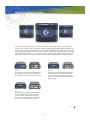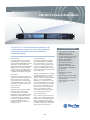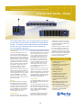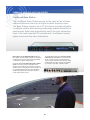
1
CLEAR-COM
COMMUNICATION SYSTEM
VINGTOR is world-renowned for its extensive knowledge in the design, construction,
installation and maintenance of integrated marine communication systems. Leveraging our
long-term experience serving the maritime industry, we offer an impressive portfolio and
provide cutting edge solutions to vessels worldwide under the brand name of VINGTOR®.
The VINGTOR brand underpins our reputation as a supplier of the most flexible, reliable and
advanced communication systems available today.
MEETING YOUR REGULATORY REQUIREMENTS
All VINGTOR products that form a part of critical communication have been tested according
to IEC 60945, IEC 60533 standards, and comply with SOLAS regulations and codes
relevant to on-board communication systems. Our systems are delivered in accordance with
the rules of all major classification societies.
FOR ALL YOUR SALES & AFTER SERVICE REQUIREMENTS
VINGTOR is a specialist provider of spare parts, repairs, maintenance contracts and refit
solutions. Responsibility and availability are our guidelines and customer support and
service a first priority.
2
ANALOG PARTYLINE BROCHURE
4
19" PANELS
17
POWER SUPPLY
21
WALL DESKTOP STATIONS
23
ACCESSORIES27
RADIO INTERFACE
30
WIRED BELTPACKS
34
WIRELESS SYSTEM - TEMPEST 2400
38
DIGITAL ECLIPSE-HX V-SERIE BROCHURE
46
CONTROLLER60
19" PANELS & DESKTOP STATIONS
62
FREESPEAK CONTROLLER & BELTPACK
64
ACCESSORIES74
3
An a l o g Part y li n e I n tercom S ystems
Clear-Com Encore
™
Highly Intuitive and Reliable
For Group Communications and Collaborations
4
Product Family Overview
From main stations to remote stations, wall-mounted speaker stations to wired beltpacks, Clear-Com Encore is the most
complete set of two-wire intercom systems for reliable group communications. The systems were designed to withstand
rugged usage in fast-paced, demanding and high intensity applications. Clear-Com Encore is highly compatible with other
Clear-Com or third-party products in order to address growing communications needs.
page
6 / Main Stations
page
8 / User Stations
Speaker Stations
CS-702
KB-701
KB-702
KB-702GM
MS-702
MS-704
V-Box
Headset Stations
Announcer Console
SB-704
page
6 / Remote Stations
HB-702
RM-702
page
AB-120
HB-704
9 / Interfaces
RM-704
page
7 / Wired RS-700
TW-47
TWC-701
SERIES Beltpacks
EF-701M
IF4W4
RS-701
RS-702
RS-703
TW-12C
4 Clear-Com Encore
5
Product Family Overview
page
10 / Peripherals
page
RCS-2700
12 / Headsets
CC-300
CC-40
CC-400
CC-26K-X4
CC-60
PIC-4704
AX-704
MA-704
TR-50
TW-704
CC-27
CC-010A
page
PRC-2
page
13 / Accessories
PTX-3
11 / Power Supplies
FL-7
MT-1
PK-7
WP-2
SP-3
WP-6
YC-36
PS-702
YC-66
Microphones
PS-704
GM-9 / GM-18
GN-250 / GN-450
page
14 / System Diagrams
Clear-Com Encore 5
6
Main/Remote Stations
CS-702 Portable Main Station
The CS-702 is a portable main station with a power supply
and a versatile intercom monitoring system. It supports
up to 40 beltpacks or 10 speaker stations on two channels.
CS-702 accepts mic or line-level audio line level program
input with an interrupt switch to override program.
MS-702 Rack-Mount Main Station
The compact, feature-laden, 1RU intercom main station
supports up to 40 RS-701 beltpacks, 10 speaker stations
or 12 headset stations on two channels. Other features
include channel A-B linking, line level program input,
Remote Mic Kill switch, and external relay circuit.
RM-702 Remote Station
The 1RU two-channel station is powered by the intercom
line. Operators can talk and/or listen on either or both
channels. The station accepts line-level audio program
input with both channels programmable for interrupt.
Microphone limiting and speaker “dipping” circuit allow
greater output before feedback.
RM-704 Remote Station
The 2RU remote station provides four independent
intercom channels with programmable front-panel buttons
for versatility. The station offers separate volume controls
for each channel, four separate audio program inputs, and
separate line level program input. Powered by the intercom
line, the system also provides three IFB channels for talent
cuing and announce button/relay for paging.
MS-704 Rack-Mount Main Station
The 2RU four-channel main station offers programmable
front-panel buttons. High-capacity, fail-safe power supply
supports up to 40 RS-701 beltpacks, 10 speaker stations
or 12 headset stations. Other features include three IFB
channels, line level program input, announce button/relay,
channel-linking button and Remote Mic Kill switch.
SB-704 Switchboard Main Station
SB-704 includes all of the features of the MS-704,
with a 4 x 10 assignment matrix in place of the internal
speaker (external speaker required). The 2RU station
features a 10-position slide switch matrix that allows
assignment of any of the 10 intercom lines to any of the
four intercom channels, an isolated separate partyline,
or an off position. Line level program input.
6 Clear-Com Encore
7
Wired RS-700 Series Beltpacks
RS-702
RS-703
RS-701
The RS-700 Series beltpacks feature state-of-the-art performance and exceptional audio clarity for partyline
communications in small- to mid-size applications. Offering a highly durable and reliable design, the beltpacks are
ideal for harsh, repetitive daily use and provide a very comfortable fit. The beltpacks also feature easy-to-select audio
and key options with DIP switch settings for Electret or Dynamic headset mics, headphone minimum level adjustment, call with talk operation, latch or non-latch keying, low or high headphone output and LED off modes. The
beltpacks have volume controls as well as talk and call buttons that are guarded against accidental operation.
RS-701
The RS-701 is a single-channel standard beltpack.
Four-pin male headset connector and three-pin
female/male loop through intercom line connectors.
RS-703
The RS-703 is a two-channel/three-pin dual listen
monaural beltpack with four-pin male headset
connector. Three-pin female/male loop through
intercom line connectors. Requires a TWC-701 TW
adaptor module.
RS-702
The RS-702 is a two-channel standard dual listen
monaural beltpack with four-pin male headset
connector. Six-pin female/male loop through
intercom line connectors. Requires YC-36 adapter
to connect with standard three-pin cabling.
Clear-Com Encore 7
8
User Stations
Speaker Stations
Headset Stations
KB-701 Single-Channel Station
The KB-701 remote speaker station connects to
a single channel of partyline intercom and operates
in half-duplex mode. It features both an integral speaker
and a flushmount electret microphone with mic limiter
and a push-to-talk button.
HB-702 Two-Channel Station
The HB-702 is a selectable two-channel wall or consolemounted headset station. The station includes microprocessor-controlled logic and switching, with a momentary/
latching talk button and visual call signaling.
KB-702/KB-702GM Two-Channel Station
The KB-702 remote speaker station permits the
user to select between two channels of partyline
communications, with the ability to talk and/or
listen on the selected channel. The user can listen
via the integral speaker, a headset or telephone-style
handset and can talk via a headset mic, a telephone
handset, or a push-to-talk microphone on the
KB-702GM version.
V-Box Portable Enclosure for KB Stations
The V-Box permits either angled or vertical portable/
desktop mounting of the KB-701, KB-702, and
KB-702GM speaker stations. Both male and female
3-pin XLR connectors are on the side panel. The
rugged metal and wood construction provides an
attractive, durable enclosure.
HB-704 Four-Channel Station
The HB-704 provides the same features as the HB-702,
but can access four intercom channels.
Announcer Console
AB-120 Announcer Console
The AB-120 On-Air Announcer Console is the ultimate
broadcast-quality tool for announcers and commentators.
The AB-120 integrates all of the inputs, outputs, and
controls necessary at the announce position, including
intercom “Talkback,” IFB receiver, and a silent “Mute”
button that provides noise-free cough and “mic on/off”
switching. Extremely flexible, the console can be easily
configured for practically any combination of audio
sources, microphones, headsets, or intercom systems
to ensure quality audio and powerful communications.
8 Clear-Com Encore
9
Headsets
CC-300
Single-ear headset features high ambient-noise attenuation
headphones and a hyper-cardioid dynamic microphone
that provide high quality audio. The headset has a flexible
design and a soft-ear pad to offer superior comfort. Able
to rotate 300-degrees, the microphone boom acts as an
on/off switch for quick microphone muting.
CC-26K-X4
The CC-26K is a single-ear, ultra-lightweight (1.3oz)
headset with a dynamic, noise-cancelling mic element
on a flexible boom. It includes a straight 5.5 foot (1.67
meter) cord with 4-pin female XLR connector.
Impedance mic/earpiece: 200/400 Ohms
Mic type: Dynamic
Impedance mic/earpiece: 200/400 Ohms
Mic type: Dynamic
CC-400
Double-ear headset features high ambient-noise attenuation
headphones and a hyper-cardioid dyanamic microphone
that provide high quality audio. The headset has a flexible
design and soft-ear pads to offer superior comfort. Able
to rotate 300-degrees, the microphone boom acts as an
on/off switch for quick microphone muting.
CC-27
The CC-27 is a single-ear wrap around headset with
a noise cancellation microphone. 4-pin XLR female
150Hz to 10kHz frequency response.
Impedance mic/earpiece: 200/90 Ohms
Mic type: Dynamic
Impedance mic/earpiece: 200/200 Ohms
Mic type: Dynamic
CC-40 and CC-60
The single- or double-ear general-purpose intercom headsets with excellent noise attenuation include a straight
5.5 foot cord (1.67 meter) with 4-pin female XLR connector.
Impedance mic/earpiece: 200/400 Ohms
Mic type: Dynamic
Que-Com Partyline System
Que-Com is a high-performance, economical partyline
communications system. This system features a wide
frequency response and high audio output. The intercom
provides an individual volume control and mic on/off
switch for each station with a permanently attached,
rugged, noise-isolating headset. The headset is connected to a rugged, all-metal diecast beltpack with belt
clip. System interconnects with a standard mic cable.
Que-Com is compatible with all Clear-Com systems.
The PK-7 is a suitable power supply option.
CC-010A IFB Ear Set
The IFB ear set includes audio driver, coiled acoustic
eartube with clothing clip, 5ft (1.5m) cable with 1/8"
(3.5mm) straight mini-jack connector.
Clear-Com Encore 9
10
Interfaces
TW-47 Two-Way Radio/Walkie-Talkie Interface
Compatible with both Clear-Com and RTS,® the TW-47
connects virtually any set of walkie-talkies to anyone
on the wired partyline intercom; simply use one
walkie-talkie as a base station. The base station radio
is keyed from the intercom call signal. Extensive RF
and EMI isolation prevent interference from entering
the intercom system. Separate transmit and receive
level controls are provided, along with audio level and
transmitter keying indicators. The stand-alone interface
is powered by the intercom line.
TWC-701 Cable Adaptor
The TWC-701 two-channel cable adapter combines
two intercom channels onto a single 3-pin XLR cable.
All two-wire (TW) beltpack models require this adapter
to support a two channel connection to a multi-channel
Clear-Com system. The TWC-701 module can drive up
to 15 RS-703 beltpacks.
EF-701M Interface
The EF-701M interface converts a single channel of
standard or TW partyline intercom to four-wire audio,
while also converting call signals to RS-422 data (and
back). The resulting four-wire audio plus RS-422 data
can then be sent to a Clear-Com matrix port, fiber optic
converter (modem) or connected to another EF-701M
over a twisted-pair cable such as CAT-5E.
TW-12C System Interface
The TW-12C connects one intercom system to another.
Optoisolation eliminates hums and buzzes. The interface
will compensate for level and impedance differences between systems. TW-12C allows Clear-Com-to-Clear-Com,
Clear-Com-to-RTS, and RTS-to-RTS system configurations.
The interface is powered by the connected intercom
system and translates “call” signals in both directions.
IF4W4 Four-Wire Interface
The IF4W4 four-channel interface connects Clear-Com
to TV cameras, two-way radios, satellite links, and other
communications devices through either headset jacks or
four-wire circuits. The IF4W4 has selective partyline capability, and features individual transmit, receive, and null
controls as well as transmit level indicators. Switchable
mic or line-level output for compatibility. The built-in test
jack and test tone provide quick nulling.
10 Clear-Com Encore
11
Peripherals
RCS-2700 Programmable Source Assignment Panel
The 2RU RCS-2700 is ideal for medium to large installations
where channel assignments to remote stations frequently
change. Eight master channel sources can be assigned
to any 24 remote station destinations, and additional
RCS-2700 units can be connected for up to 15 sources
and 72 destinations. It can store 14 presets.
PIC-4704 Program Interrupt Controller
Each IFB controller handles up to four talent receivers.
For use with MA-704 and AX-704 IFB Control Panels or
intercom stations. This unit contains the circuitry for
selecting one of two program sources, sending the program
to the IFB channels, and interrupting it via the talent
control station. The controller has variable audio program
dip-level, monaural or stereo/split-feed outputs, and improved and intuitive user interface. It requires a 6-pin XLR
cable for connection to MA-704/AX-704 control panels.
MA-704/AX-704 IFB Control Panel
These console-mount or rack-mount units control
“program interrupt” (IFB) to the talent. The MA-704
includes a gooseneck microphone connector, illuminated
“All Talent”, and four individual talent push buttons. The
AX-704 permits expansion in multiples of four. Both accept
the “hot mic out” from a Clear-Com station. An optional
CEP-RK rack mount fixture is available for the MA-704
and AX-704 panels.
TR-50 Talent Receiver
The TR-50 is an amplified single-channel talent beltpack
with volume control. It connects to the program interrupt
controller with a standard microphone cable. It has a
mini earphone jack output and includes a talent earset.
It should be paired with the CC-010A IFB ear set.
PRC-2 UHF Wireless IFB Receiver
The IFB receiver has default UHF frequencies that can
be set without power or a transmitter signal. Up to five
additional frequencies can be stored in scan mode. The
design uses +/-20 kHz FM deviation for efficient use of the
bandwidth with compandor noise reduction circuitry for
an excellent signal to noise ratio. The receiver will drive a
wide variety of earbuds, headphones and induction neck
loops at substantial levels, with loads from 16 Ohms to
600 Ohms. It should be paired with the CC-010A IFB ear set.
Not available for CE countries.
PTX-3 UHF Wireless IFB Transmitter
The wireless IFB transmitter base station has 256 selectable
UHF frequencies at 100 kHz increments. Microprocessor
control enables easy operation and eliminates transients
at turn-on and turn-off. Transmitter can be used as a
standalone device or rack mounted with the PRK-2 kit.
Not available for CE countries.
Clear-Com Encore 11
12
Power Supplies
PS-702 Two-Channel Power Supply
The 1RU PS-702 can deliver 1.2 amps at 30 volts DC
to two channels. This is sufficient to power up to 40
beltpacks, 10 speaker stations, or 12 headset stations
even under the most demanding conditions. Either
channel is capable of supplying up to 1.2 amps.
The full current capacity may be divided between
the two channels.
PS-704 Four-Channel Power Supply
The 1RU PS-704 is a four-channel power supply that
features Clear-Com’s “fail-safe” design for maximum
reliability. The power supply delivers 1.2 amps at 30 volts,
supplying power for one to four channels of intercom.
It will support up to 40 beltpacks, 10 speaker stations
or 12 headset stations.
PK-7 Lightweight Power Supply
The PK-7 power supply will support up to 30 Que-Com
headset stations or five standard RS-700 series beltpacks. It is line and load regulated and short-circuit
protected. Power supply fits into a single rack space.
12 Clear-Com Encore
13
Accessories
FL-7 Call Signal Flasher
The FL-7 call signal flasher has a new
LED design with dimmer. It provides
both a visual and audible indication of
a call signal on the intercom channel.
The front panel mode switch selects
flasher, ring or both.
WP-2 Intercom Outlet Wall Plate
The selectable two-channel WP-2 wall
plate connects to single-channel beltpacks such as the RS-701. The 3-pin
male XLR connector with two-position
channel-selector switch allows user to
talk on either of two intercom channels.
WP-6 Intercom Outlet Wall Plate
The WP-6 wall plate is used with twochannel beltpacks such as the RS-702.
6-pin male XLR connector connects
user with two intercom channels.
HS-6 Telephone-Style Handset
Telephone-style handset with wall/
console mount hanger, push-to-talk
switch includes a 6-foot coil cord with
4-pin female XLR connector.
SP-3 Line Splitter
The SP-3 line splitter is a one-femaleinput to three-male-output cable
assembly for intercom line splitting.
YC-36 “Y” Adapter
The YC-36 “Y” adapter plugs into the
6-pin male XLR intercom connector on
a RS-702 or beltpack. The other end
provides two 3-pin female XLR connectors, for separate line connection
to channels A and B.
PT-7 Hand-Held Mic
The rugged, push-to-talk, hand-held
PT-7 microphone with mounting clip
includes a 5-foot coil cord with 4-pin
female XLR connector.
GM-9/GM-18 Gooseneck Mics
The GM-9 (9" length) and GM-18 (18"
length) gooseneck microphones feature
a gold-plated, threaded, and locking
three-conductor quarter-inch phone
plug connector. A fitted windscreen is
included. The uni-directional electret
condenser mic element has a side and
rear rejection of greater than 6dB
between 100Hz and 10kHz.
GN-250/GN-450
Gooseneck Mics
GN-250-25cm/10in Plug-in
gooseneck microphone
GN-450-45cm/18" Plug-in
gooseneck microphone
YC-66 6-Pin Line Splitter
The YC-66 is a one 6-pin male XLR
connector that splits into two 6-pin
female connectors.
MT-1 Isolator Circuit Card
The MT-1 electrically isolates the
ground, power, and signaling lines
when connecting between two
partyline intercom systems. Use one
card per channel.
Clear-Com Encore 13
14
SYSTEM DIAGRAMS
System
System Diagrams
Diagrams
Four-Channel TV News System
RS-701
RS-701
TV BR OADCAST STATION
System Diagrams
Cable/School Television Studio
RS-701
RS-701
RS-701
RS-701
RS-701
Stage Production
Four-Channel System Using SwitchBoard Main Station
RS-701
RS-701
RS-701
RS-701
RS-701
RS-701
RS-701
YC-36
RS-702
RS-702
RS-701
RS-701
RS-701
RS-701
RS-701
RS-701
RS-701
RS-701
RS-701
Sports Production
RS-701
RS-701
RS-701
RS-701
OB Truck
14 Clear-Com Encore
15
RS-701
RS-701
RS-701
RS-701
RS-701
RS-701
RS-701
RS-701
RS-701
RS-701
RS-701
RS-701
RS-701
RS-701
RS-701
RS-701
RS-701
SYSTEM DIAGRAMS
KB-702GM
Sports Production
System
Diagrams
System
Diagrams
Stand-Alone
System,
1 Location, 4 Talent
RS-701
RS-701
RS-701
RS-701 RS-701
RS-701
RS-701
RS-701
RS-701
SP-3
RS-701
RS-701
RS-701
RS-701
RS-701
RS-701
RS-701
RS-701
RS-701
RS-701
Stage
Production
Stage
Production
ction
RS-701
RS-701
RS-701
RS-701
STAG E P R ODU C TION
Typical Portable System
RS-701
RS-701
RS-701
RS-701
RS-701
RS-701
RS-701
RS-701
Theater
RS-701
RS-701
RS-701
RS-701
RS-701
RS-701
RS-701
RS-701
RS-701 RS-701
RS-701
RS-701
RS-701
RS-701
RS-701 RS-701
RS-701 RS-701
RS-701 RS-701
RS-701
RS-701
KB-702GM
KB-702GM
Sports
Production
Production
OBSports
Truck
uction
OB Truck
OB Truck
RS-701
RS-701
RS-701
RS-701
RS-701
RS-701
MS-702
RS-701
RS-701
RS-701
RS-701
SP-3
SP-3
RS-701
O B TR U C K
ENG/EFP Truck
RS-701
RS-701
RS-701
RS-701
RS-701
RS-701
STANDARD TELEPHONE INTERFACE OR
VoIP CLIENT e.g. CONCERT SERVER
STANDARD TELEPHONE INTERFACE OR
VoIP CLIENT e.g. CONCERT SERVER
MS-702
RS-701
RS-701
Clear-Com Encore 15
16
OB Tr
Coach to Spotter System-Portable
S PO RT S PR O D U C T IO N
T V B R O A DC A S T S TAT IO N
grams
RS-7
RS-701
Clear-Com Encore
TM
MS-702 Two-Channel Main Station
MS-702 Front Panel
The MS-702 is a one-rack-space, two-channel main station with a
regulated 1.2-amp “fail-safe” power supply, individual channel short-circuit
protection, and a versatile intercom monitoring system. It supports two
intercom channels with up to 40 beltpacks or 10 speaker stations. It features
Clear-Com’s excellent speech intelligibility in both high- and low-noise
environments.
Monitoring System
The MS-702 can monitor intercom activity on one or both channels with
individual listen-level controls. Monitoring intercom activity is possible
through a headset or the internal loudspeaker. The high-sensitivity internal
speaker provides intelligible communication in the typical active production
environment.
Talk Selection
The MS-702 contains mic preamps with limiters, and speech-shaping
circuits for enhanced intelligibility. An individual electronic momentary/
latching talk button is provided for each channel. These buttons light
dimly when latched - blue-color LED while in stand-by and amber-color LED
when latched. The channels may be accessed separately or simultaneously
without tying them together. An optional gooseneck mic is available.
Announce Output
For paging applications, the MS-702 provides a balanced, line-level
output signal to a1/ 4-inch TRS connector on the rear panel. The front
panel “Announce” button activates the output and the Announce relay.
The relay circuit, on a separate1/ 4-inch TRS connector, is typically used to
mute control-room monitors during live announcements.
Visual And Audible Signaling
Visual “call” signaling attracts the attention of operators who have removed
their headsets or turned off their speakers. Call buttons for each channel
signal all stations on that party line by flashing brightly. Along with the visual
signal, the station’s speaker will emit an audible signal if the remote station
operator holds the Call button for more than 2 seconds.
Remote Mic Kill (RMK)
The MS-702 is equipped with a global RMK button. It will turn off the microphone talk circuits of all Clear-Com beltpacks in the system, eliminating
extraneous noise from the “open” headset microphones.
Program Input
The MS-702 accepts a line-level external program input for monitoring in the
headset and speaker, and/or mixing with intercom audio on either or both
channels. When Interrupt is selected, the program signal is interrupted when
the Talk button is pressed.
Power Supply & System Protection
The MS-702 provides visual indication of power
supply conditions. In the event of a short circuit
or current overload on a channel, that channel
will shut down while the other one continues
to operate. As soon as the fault condition is
removed, the “auto-reset” circuitry will restore
power to that channel - even under full load
conditions.
Simple Set-Up
The MS-702 connects to remote stations with
standard, two-conductor shielded mic cable.
User-selectable setup dip switches are provided
on the rear panel.
Features:
• Supports up to 40 beltpacks or 10 speaker
stations on two channels and 12 headsets
• Separate short-circuit protection for each
channel
• Dual-action electronic momentary/
latching “talk” buttons
• Program feed to both channels, with
selectable “Program Interrupt” (IFB)
• “Call” signal buttons for each channel
• Global “Remote Mic Kill”
• Announce output with relay
• Microphone limiting
• Volume controls for each channel
• Visual and audible “Tone Alert” signaling
• Channels A & B “Link” switch
• Built-in speaker
• Optional gooseneck mic
• External switchable line termination on
each channel
• Universal voltage power supply for
100-240 VAC operation
www.clearcom.com
17
Clear-Com Encore
TM
MS-702 Two-Channel Main Station
Technical Specifications:
dBu is an absolute measurement. 0 dBu is
referenced to 0.775 volts RMS
MS-702 Back Panel
Panel Microphone Input
Input Type:
Input Impedance:
Mic Limiter Threshold:
Mic Limiter Range:
Electret
>=2KΩ
0 dBu ±3 dB
>= 20 dB
Headset Microphone Input
Input Type:
Input Impedance:
Mic Limiter Threshold:
Mic Limiter Range:
Dynamic
>= 1KΩ
0 dBu ± 3dB
>= 15 dB
Program Line Input
Maximum Level
before Clipping:
Input Impedance:
Headset Output
Load Impedance:
Output Impedance:
Output Limiter Threshold:
Maximum Output Level
before Distortion:
Speaker Output
Load ImpedancE:
Max Output Level before
1% Distortion:
>= 20 dBu
>= 5KΩ
>= 8Ω
<= 25Ω
+5 dBu ± 3 dB
>= 17 dBu
>= 4Ω
20 dBu ± 2 dBu
Party Line Output
Off Noise:
Output Impedance:
< -74 dBu
>10 KΩ
Party Line Input
Crosstalk:
Max level before Clipping:
Sidetone Null Capability:
< -60 dB
>= 12 dBu
> 25 dB
Stage Announce/Balanced Line Out
Type:
Balanced
Output Impedance:
>= 200Ω
Load Impedance:
>= 600Ω
IFB/Hot Mic
Type :
Output Impedance:
Load Impedance:
Frequency Response
Panel Mic - Party Line:
Headset Mic - Party Line:
Headset Mic - Line Out:
Program Input - Party Line:
Program Input
- Headset Out:
Program Input
- Speaker Out:
Party Line - Headset Out:
Party Line - Speaker Out:
MS-702
Unbalanced
180Ω
>= 600Ω
600 - 10KHz ± 3dB
200 - 12KHz ± 3 dB
200 - 12KHz ± 3 dB
100 17KHz ± 3 dB
200 - 10KHz ± 3 dB
300 - 10KHz ± 3 dB
200 - 10KHz ± 3 dB
300 - 10KHz ± 3 dB
Max Distortion
Panel Mic - Party Line:
Headset Mic - Party Line:
Headset Mic - Line Out:
Program Input - Party Line:
Program Input - Headset Out:
Program Input - Speaker Out:
Party Line - Headset Out:
Party Line - Speaker Out:
<= 0.5%
<= 0.5%
<= 0.5%
<= 0.2%
<= 0.2%
<= 0.5%
<= 0.2%
<= 0.5%
Noise
Panel Mic - Party Line:
Headset Mic - Party Line:
Headset Mic - Line Out:
Program Input - Party Line:
Program Input - Headset Out:
Program Input - Speaker Out:
Party Line - Headset Out:
Party Line - Speaker Out:
< -65 dBu
< -70 dBu
< -55 dBu
< -85 dBu
< -60 dBu
< -60 dBu
< -50 dBu
< -50 dBu
Max Gain
Panel Mic - Party Line:
>= 37 dB
Headset Mic - Party Line:
41 dB ± 2 dB
Headset Mic - Hot Mic Out: 55 dB ± 3 dB
Headset Mic - Announce Out: 55 dB ± 3 dB
Program Input - Party Line:
>= -16 dB
Program Input - Headset Out: >= 18 dB
Program Input - Speaker Out: >= 24 dB
Party Line - Headset Out:
>= 34 dB
Party Line - Speaker Out:
>= 40 dB
Min Gain
Panel Mic - Party Line”
Mains Power
Input Voltage Range:
Input Frequency Range:
Input Power:
Output Voltage :
Output Current per Channel
(Continuous):
Output Current per Channel
(Peak):
Short Circuit Recovery
Time (1st short):
Short Circuit Recovery Time
>= 20 shorts in 20sec:
<= 25 dB
100 - 240 VAC
50 - 60 Hz
<= 60 VAC
30 VDC ± 0.5V
1.2 A
2 A (Do not exceed
the 1.2A rating for
more than 2 seconds
per 1 minute period)
<= 0.5 sec
Rear Panel Connectors
Intercom:
Announce Out:
Announce Relay:
Program:
Hot Mic / IFB Interface:
AC Power:
(6) XLR-3M (3 per
channel)
(1) XLR-3M (audio)
(1) 1/4 in. (0.64 cm)
phone jack (relay)
(1) XLR-3F
(1) 1/4 in. (0.64 cm)
phone jack
IEC 320 connector
Rear Panel Controls
(2) Termination On-Off switches
(8) Option switches
(1) Power switch
(1) Tone alert volume control
Front Panel Connectors
Panel Mic:
Headset:
(1) 1/4 in. (0.64 cm)
panel mounting jack
(1) XLR-4M
Front Panel Controls & Indicators
(1) Panel / headset mic switch
(1) Announce button
(1) Party line link button
(2) Program
ON-OFF-INTERRUPT switches
(3) Program level controls
(2) Listen controls
(2) Sidetone null controls
(2) Talk buttons
(2) Call buttons
(1) Tone alert button
(1) RMK button
(1) Speaker ON-OFF switch
(2) Short LEDs
Environmental
32 - 122˚F (0 - 50˚C)
Dimensions
19 in. W x 1.75 in. H x 6.5 in. D
(483 mm x 44 mm x 165 mm)
Weight
6.06 lbs. (2.75 kg)
<= 20 sec
Station Capacity
Notice About Specifications
Up to 40 RS-601 beltpacks or 10 speaker stations or While Clear-Com makes every attempt to maintain the
12 headset stations distributed over both channels accuracy of the information contained in its product
manuals, that information is subject to change without
notice. Performance specifications included in this manual
are design-center specifications and are included for
customer guidance and to facilitate system installation.
Actual operating performance may vary.
www.clearcom.com
Americas and Asia-Pacific Headquarters California, United States Tel: +1.510.3337.6600
Europe, Middle East and Africa Headquarters Cambridge, United Kingdom Tel: +44 1223 815000
China Office Beijing, P.R. China Tel: +86-10-65811360/65815577
© 2011. Clear-Com LLC. All rights reserved. ® Clear-Com, the Clear-Com logo, and Clear-Com Encore are registered trademarks of HM Electronics, Inc.
18
Clear-Com Encore
TM
RM-702 Two-Channel Remote Intercom Station
RM-702 Front Panel
The RM-702 is one of a series of professional remote intercom stations.
The remote speaker/headset station allows two-channel selectable talk
and listen in one rack space. The operator can talk and listen on either
channel separately or talk to both channels simultaneously without tying
the two channels together. Specially contoured audio response provides
excellent speech intelligibility, even in high-noise environments.
The RM-702 can monitor intercom activity on one or both channels with
individual Listen Level controls. Monitor intercom activity through a headset, the internal speaker, or both at once. The 4-watt output amplifier can
drive the wide-response speaker or Clear-Com headset to very high output levels - more than enough volume for the noisiest environment.
A “speaker dipping” circuit helps to reduce feedback when stations are
placed in close proximity to each other.
The station has a convenient speaker “on/off” switch when private
conversation via the headset is desired. The station accepts dynamic
headsets or optional plug-in gooseneck mic.
Talk Selection
The operator can talk on either of the channels separately or on both at
once. A proprietary contoured frequency response in the mic pre-amp
enhances speech intelligibity in high-noise environments. Illuminated
dual-action talk buttons are electronic momentary or latching; blue-color
LED while in stand-by, and amber-color LED when latched. The latching
feature may be disabled if desired. The station also features a headset
or microphone selector switch. The talk buttons can also be remote
controlled with a footswitch.
Signaling
The RM- 702 features individual call buttons and visual call signaling to
attract the attention of operators who have removed their headsets or
turned off their speakers. The visual signaling flashes the illuminated talk
button when a call is received. The call-signaling feature can be
programmed to the talk buttons.
AUX. Audio Input and Program Interrupt (IFB)
The station can accept either a balanced or unbalanced line-level audio
input through the DB-15 connector on the rear panel. The program can be
monitored at the station or fed into channel B, where it can also be set up
for IFB/Program interrupt from this or any other Encore station.
Additional Features
Each channel has its own sidetone control.
This allows the operator to vary the level of their
own voice as heard in the headset. When the
announce button is pressed, the microphone
signal is routed to a connector on the back panel.
Relay contacts are also available for muting
speakers or turning on a signal light. The station
accepts Clear-Com’s 9” or 18” gooseneck
microphone.
Features:
• Selectable one- or two-channel
communication
• Individual listen volume controls
• Momentary/latching talk buttons
• Individual call buttons
• Visual call signaling
• Balanced audio input with program
interrupt (IFB)
• “Hot mic” and line-level outputs
• Studio announce output with relay
• Optional plug-in gooseneck mic
• Wide-range high-output speaker
• One rack space
• LED buttons for talk, call, announce,
link, all talk, and mic on
Applications
• ENG and EFP trucks
• Production studio consoles
• Single-channel program interrupt
system “IFB” for talent cueing
• Portable sound system equipment racks
• Low-profile “top of console” locations
• Any 2-channel intercom requirement
where rack space is at a premium
www.clearcom.com
19
Clear-Com Encore
TM
AFFIX
SERIAL LABEL
HERE
dBu is an absolute measurement. 0 dBu is
referenced to 0.775 volts RMS
Panel Microphone Input
Input Type :
Input Impedance:
Mic Limiter Threshold:
Mic Limiter Range:
Electret
>=2KΩ
0dBu ±3dB
>= 20dB
Headset Microphone Input
Input Type:
Input Impedance:
Mic Limiter Threshold:
Mic Limiter Range:
Dynamic
>= 1KΩ
0dBu ± 3dB
>= 15dB
Program Line Input
Maximum Level before
Clipping:
Input Impedance:
>= 20dBu
>= 5KΩ
Headset Output
Load Impedance:
Output Impedance:
Output Limiter Threshold:
Maximum Output Level
before Distortion:
Speaker Output
Load Impedance:
Max Output Level before
1% Distortion:
>= 8Ω
<= 25Ω
+5dBu ± 3dB
>= 17dBu
>= 4Ω
20dBu ± 2dBu
Party Line Output
Off Noise:
Output Impedance:
< -74dBu
>10KΩ
Party Line Input
Crosstalk:
Max level before Clipping:
Sidetone Null Capability:
< -60dB
>= 12dBu
> 25dB
ro
Hot Mic/
C-C IFB
System
Accessory
P
Technical Specifications:
P g
ro F
M g ee
o F d
M m ee A
o Ta d
C m lk B
a Ta
C ll O lk A
a
In ll O n Ta B
tr
In pt n Ta lk
tr
A
Lo pt An lk
n B
Lo ng Ex c
Lin t IF
n
P g
ro
e B
P g Lin A
ro In e
g t B
In A
tB
RM-702 Two-Channel Remote Intercom Station
Off
On
RM-702
Intercom Channel A
Intercom Channel B
RM-702 Back Panel
Max Distortion
Panel Mic - Party Line:
Headset Mic - Party Line:
Headset Mic - Line Out:
Program Input - Party Line:
Program Input - Headset Out:
Program Input - Speaker Out:
Party Line - Headset Out:
Party Line - Speaker Out:
<= 0.5%
<= 0.5%
<= 0.5%
<= 0.2%
<= 0.2%
<= 0.5%
<= 0.2%
<= 0.5%
Noise
Panel Mic - Party Line:
Headset Mic - Party Line:
Headset Mic - Line Out:
Program Input - Party Line:
Program Input - Headset Out:
Program Input - Speaker Out:
Party Line - Headset Out:
Party Line - Speaker Out:
< -65dBu
< -70dBu
< -55dBu
< -85dBu
< -60dBu
< -60dBu
< -50dBu
< -50dBu
Max Gain
Panel Mic - Party Line:
>= 37dB
Headset Mic - Party Line:
41dB ± 2dB
Headset Mic - Hot Mic Out: 55dB ± 3dB
Headset Mic - Announce Out: 55dB ± 3dB
Program Input - Party Line:
>= -16dB
Program Input - Headset Out: >= 18dB
Program Input - Speaker Out: >= 24dB
Party Line - Headset Out:
>= 34dB
Party Line - Speaker Out:
>= 40dB
Min Gain
Panel Mic - Party Line:
<= 25dB
Stage Announce/Balanced Line Out
Type:
Balanced
Output Impedance:
>= 200Ω
Load Impedance:
>= 600Ω
Power
Input Voltage Range:
Input Current (Idle):
Input Current (Max):
20-30 VDC
<= 90mA
<=110mA
IFB/Hot Mic
Type:
Output Impedance:
Load Impedance:
Unbalanced
180Ω
>= 600Ω
Rear Panel Connectors
Intercom:
Frequency Response
Panel Mic - Party Line:
Headset Mic - Party Line:
Headset Mic - Line Out:
Program Input - Party Line:
Program Input - Headset Out:
Program Input - Speaker Out:
Party Line - Headset Out:
Party Line - Speaker Out:
600 - 10KHz ± 3dB
200 - 12KHz ± 3dB
200 - 12KHz ± 3dB
100 - 17KHz ± 3dB
200 - 10KHz ± 3dB
300 - 10KHz ± 3dB
200 - 10KHz ± 3dB
300 - 10KHz ± 3dB
Hot Mic / IFB Interface:
Accessory:
(2) XLR-3M
(1 per channel)
(2) XLR-3F
(1 per channel)
(1) 1/4 in. (0.64 cm)
phone jack
(1) DB-15F
Front Panel Connectors
Panel Mic:
Headset:
(1) 1/4 in. (0.64 cm)
panel mounting jack
(1) XLR-4M
Front Panel Controls & Indicators
(1) Panel / headset mic switch
(1) Announce button
(2) Program send level controls
(1) Program monitor level control
(2) Listen controls
(2) Sidetone null controls
(2) Talk buttons
(2) Call buttons
(1) Speaker ON-OFF switch
Environmental
32 - 122˚F (0 - 50˚C)
Dimensions
19 in. W x 1.75 in. H x 7.0 in. D
(483 mm x 44.5 mm x 178 mm)
Weight
5.2 lbs. (2.36 Kg)
Notice About Specifications
While Clear-Com makes every attempt to maintain
the accuracy of the information contained in its product
manuals, that information is subject to change without
notice. Performance specifications included in this manual
are design-center specifications and are included for
customer guidance and to facilitate system installation.
Actual operating performance may vary.
Rear Panel Controls
(12) Option switches
www.clearcom.com
Americas and Asia-Pacific Headquarters California, United States Tel: +1.510.337.6600
Europe, Middle East and Africa Headquarters Cambridge, United Kingdom Tel: +44 1223 815000
China Office Beijing, P.R. China Tel: +86-10-65811360/65815577
© 2011. Clear-Com LLC. All rights reserved. ® Clear-Com, the Clear-Com logo, and Clear-Com Encore are registered trademarks of HM Electronics, Inc.
20
Clear-Com Encore
TM
PS-702 Two-Channel Intercom Power Supply
PS-702 Front view
The PS-702 can supply up to 2 amps at 30 volts DC to two channels in a
1-RU. This is sufficient to power up to 40 beltpacks,10 speaker stations, or
12 headset stations even under the most demanding conditions. Either
channel is capable of supplying up to 1.2 amps. The full current capacity
may be divided between the two channels.
Clear-Com’s advanced fail-safe design can sense the difference between
a short and an overload. Should a problem occur, each channel’s DC
overload/fault LED identifies the power supply’s response to the problem:
solid means an overload is sensed, but still powered; blinking means
power has been temporarily cut off to protect the power supply. If both
channels are operating and one channel has a fault, the other channel
will continue to operate normally. Power is restored to the shorted or
overloaded channel in a little as .5 seconds. With our exclusive Intelligent
Fault/Overload Sensing (IFOS), the PS-702 will dynamically increase this
time period before attempting another reset until the fault or overload
is corrected. This function significantly extends component life. And
there is no need to disconnect stations for the power supply to reset.
The unit also offers a convenient front panel intercom line jack, switchable
to either channel. This can be quite handy for trouble-shooting or simply a
time saver when quick access to either intercom line is needed. A 440Hz
tone is available on either or both channels and is indispensable for
system diagnostics and set-up. Simply flip a switch, set a level, and go.
Like all current Clear-Com Party-Line power supplies, two or more units
can be connected in parallel for increased system capacity or backup
redundancy. Multiple units will automatically synchronize their response
to power faults and overloads. The PS-702 can also operate as a singlechannel unit by using the front-panel A+B link switch.
Features:
• Provides up to 2 amps in only 1RU
• Supports up to 40 beltpacks, 10
speaker stations or 12 headset
stations
• Exclusive IFOS Intelligent Fault/
Overload Sensing for system reset
• Front panel intercom line jack
selectable for either channel
• A+B Link switch for single channel
operation
• Balanced program input with global
and individual channel controls
• Universal power supply accepts
100-240 VAC
• Overload/fault indicator for each
channel
• Built-in test tone generator for set
up and diagnostics
• Switchable terminations for each
channel
• Works in parallel with other power
supplies and main stations
• UL Listed and CE certified
www.clearcom.com
21
Clear-Com Encore
TM
PS-702 Two-Channel Intercom Power Supply
TERM
A
OFF
PS-702
TERM
B
OFF
ON
CHANNEL A
LEVEL
ADJUST
ON
PROGRAM INPUT
CHANNEL B
PS-702 Back Panel
Technical Specifications:
dBu is an absolute measurement. 0 dBu is
referenced to 0.775 volts RMS
Program Line Input
Maximum Level before Clipping: >= 20dBu
Input Impedance:
>= 5KΩ
Frequency Response
Program Input - Party Line:
200 - 20KHz ± 3dB
Max Distortion
Program Input - Party Line:
<= 0.2%
Noise
Program Mic Input - Party Line:< -70dBu
Short Circuit Recovery Time
(1st short):
<= 0.5 sec
Short Circuit Recovery Time: >= 20 shorts in
20sec) <= 20 sec
>= -16dB
Rear Panel Controls
(2) Termination On-Off switches
(1) Volume control
Min Gain
Program Input - Party Line:
<= -20dB
Front Panel Connectors
Intercom (1) XLR-3M
100 - 240 VAC
50 - 60 Hz
<= 60 VAC
30 VDC ± 0.5V
1.2 A
2 A (Do not exceed
the 1.2A rating for
more than 2 seconds
per 1 minute period)
Dimensions
19 in. W x 1.75 in. H x 7.5 in. D
(483 mm x 44 mm x 190 mm)
Station Capacity
Up to 40 RS-601 beltpacks or 10 speaker stations or
12 headset stations distributed over both channels Weight
6.16 lbs. (2.80 kg)
Rear Panel Connectors
Intercom:
(6) XLR-3M (3 per
channel)
Program:
(1) XLR-3F
AC Power:
IEC 320 connector
Max Gain
Program Input - Party Line:
Mains Power
Input Voltage Range:
Input Frequency Range:
Input Power:
Output Voltage:
Output Current per Channel
(Continuous):
Output Current per Channel
(Peak):
Environmental
32˚ - 122˚F (0˚ - 50˚C)
Front Panel Controls & Indicators
(1) Intercom channel switch
(1) A+B link switch
(2) Program switch
(2) Send level controls
(1) Test tone switch
(2) Overload LEDs
(1) Link indicator LED
(1) Power indicator LED
(1) Power switch
Notice About Specifications
While Clear-Com makes every attempt to maintain the
accuracy of the information contained in its product
manuals, that information is subject to change without
notice. Performance specifications included in this manual
are design-center specifications and are included for
customer guidance and to facilitate system installation.
Actual operating performance may vary.
www.clearcom.com
Americas and Asia-Pacific Headquarters California, United States Tel: +1.510.337.6600
Europe, Middle East and Africa Headquarters Cambridge, United Kingdom Tel: +44 1223 815000
China Office Beijing, P.R. China Tel: +86-10-65811360/65815577
© 2011. Clear-Com LLC. All rights reserved. ® Clear-Com, the Clear-Com logo, and Clear-Com Encore are registered trademarks of HM Electronics.
22
Clear-Com Encore
TM
KB-702, KB-702GM, KB-701 Remote Speaker Stations
These versatile stations may be wall or
console mounted in a standard U.S. 4-gang
electrical box, or may be mounted in the
optional V-Box for desktop, surface-mount,
or portable applications.
KB-702
The KB-702 remote speaker station permits the user to select
between two channels of party-line communications, with the ability
to talk and/or listen on the selected channel. The user can listen via
the integral speaker, or may use a headset or telephone-style handset
- and can talk via a headset mic, a telephone handset, or a push-totalk microphone.
The KB-702GM adds a gooseneck-mic connector and VOX circuitry,
for hands-free full-duplex communications without a headset.
A switch allows the user to choose between the optional GM-9 or
GM-18 microphone and the headset connector. The adjustablesensitivity, close-in VOX feature automatically detects the user’s voice
at the mic and dips the level of the integral speaker while increasing
the gain of the microphone, performing in the opposite manner when
listening. The potential for acoustic feedback is minimized while
permitting natural conversation levels and dynamics.
Microprocessor-controlled logic and switching yields a feature-rich
intercom station in a compact format. Electronic switching for the
talk button, blue-color LED (on), amber color LED (off), permits
momentary or latching operation. For call signaling, a bright LED
lights when a call is activated on a connected intercom channel.
A defeatable audible call signal, with level control, is also provided.
Separate level controls are provided for intercom level and for
balanced program input. A local program source may be fed to the
station, allowing the user to monitor that source while remaining in
contact on the intercom system. The balanced program input can
also be used in conjunction with the stage-announce output of a main
station to provide a paging interrupt, allowing paging at the KB station
even if the intercom volume control is turned down.
A set of option dip switches is located at the top of the circuit board.
Switches are provided for mic-latch disable (momentary-only talk),
long-line operation, channel selection, call signal tracking, and audible
call signaling.
23
Either of the stations may be used with the
optional 4-wire or TW (two channels on a
single mic cable) daughter boards. On the
TW board, the stations become plug in
compatible with a Clear Com TW system.
The 4-wire board creates separate send and
receive circuits, so that the station may be
attached to fiber-optic lines or other audio
routing systems with 4-wire connections.
The stations are powered by the intercom
line or by a local power supply when used
with the optional 4-wire daughter board.
Features:
• Selectable two-channel, full-duplex
operation
• Microprocessor-controlled logic and
switching
• Momentary/latching talk button
• Visual and audible call signaling,
with bright LED indicator
• Balanced local program input with
separate level control
• Internal controls for call signal tracking,
mic latch disable, and other functions
• Use with headset or handset, with
integral speaker for monitoring
• KB-702GM adds mic jack for gooseneck mic plus VOX circuitry
• Optional TW and 4-Wire daughter
boards provided additional flexibility
• Wall or console mount, or optional
V-Box for portable or desktop use
• LED buttons for talk, listen, call,
announce, link, all talk, or mic on.
www.clearcom.com
Clear-Com Encore
TM
KB-701 Single-Channel Speaker Station
The KB-701 may be wall or console
mounted in a standard 4-gang electrical
box, or may be mounted in the optional
V-Box for desktop, surface-mount, or
portable applications. It may be used with
the optional 4-wire or TW (two channels
on a single mic cable) daughter boards.
The station is powered by the intercom
line or by a local power supply when used
with the optional 4-Wire daughter board.
KB-701
The KB-701 remote speaker station connects to a single channel
of party-line intercom, and operates in half-duplex mode, similar
to a walkie-talkie. It features both an integral speaker and a flushmount electret microphone with mic limiter and a push-to-talk
button. The station may be programmed via two internal dip
switches to operate in four different modes, activated by other
stations within the intercom system. The different operating
modes are activated using the call signaling function of another
station, which allows for individual control of the speaker and
microphone.
Microprocessor-controlled logic and switching yields a featurerich intercom station in a compact format. An electronic
momentary-only talk button activates the talk function. Use
the talk button or the reomote control from another station to
activate the mic. A blue-colour LED indicates that the mic is
on, while an amber-color LED indicates the mic is off. Mic
sensitivity is selectable for either close or distant voice pickup.
The KB-701 offers both visual and audible call signaling, gaining
the attention of the user when not at the station. A red-color
LED lights when a call is activated on a connected intercom
channel. A defeatable audible call signal, with level control, is
also provided. Separate level controls are provided for intercom
level and for balanced program input. A local program source
may be fed to the station, allowing the user to monitor that
source while remaining in contact on the intercom system.
The balanced program input can also be used in conjunction with
the stage-announce output of a main station to provide a paging
interrupt. This would allow paging at the station even if the
intercom volume control is turned down. In addition, the
intercom volume control of the KB-701 can be internally set so
that an incoming message would still be audible, even if the
control was turned all the way down.
24
Features:
• Single-channel, push-to-talk speaker
station
• Four different modes of operation,
internally programmable
• Microprocessor- controlled logic
and switching
• Flush-mounted internal microphone
• Visual and audible call signaling, with
bright LED indicator
• Balanced local program input with
separate level control
• Optional TW and 4-Wire daughter
boards provide additional flexibility
• Wall or console mount, or optional
V-Box for portable or desktop use
• LED buttons for talk, listen, call,
announce, link, all talk, or mic on.
www.clearcom.com
Clear-Com Encore
TM
KB-702, KB-702GM, KB-701 Remote Speaker Stations
Accessories
4-wire Option Module
The 4-wire option module plugs into pins
on the KB- 702, KB- 702GM, and KB-701
speaker stations. It consists of the necessary
circuitry and connectors to convert any of
these stations to 4-wire operation, and can
accept two 4-wire connections. This option
allows the speaker station to be used at
much longer distances than are possible
with a standard two-wire intercom line, and
also permits the station to operate via fiber
optic cable and other devices with 4-wire
connections. The module provides a
transformer- isolated audio connection,
and does not transfer the call signal.
A station using this option module must
be locally powered.
KB-702 in a V-Box
Dimensional Drawings
1.25*
(32)
4.50 3.25
(114) (83)
8.25
(210)
* 1.75" for
KB-702GM
or with
option
modules
5.4
(137)
8.25
(210)
.5
(13)
KB-211 Rear View
KB-702 Sideview
TW Option Module
The option module plugs into pins on the
KB-702, KB-702GM, and KB-701 speaker
stations. This option allows the station to
send and receive two channels of audio on
a single 3-pin micro-phone cable. With the
TW module in place, the station can become
a part of a Clear-Com TW system, and is
compatible with TW beltpacks and other
components.
.5
(13)
2.85
(72)
8.27
(211)
V-Box Front View
V-Box Desktop/Wall-Mount
Enclosure
The V-Box converts any of the KB speaker
stations into a desktop, portable, or wallmount unit. The station panel may be
secured with four screws in one of the two
mounting spaces, for either an angled or a
vertical panel orientation. A blank plate with
mounting keyholes is provided to cover the
second mounting space. 3-pin XLR male
and female connectors are mounted on the
side panel, wired to a connector block for
easy connection to the speaker station.
The rugged metal and stained-wood
enclosure is both durable and attractive
for long-term professional use.
6.04
(153)
5.56
(141)
V-Box Side View
www.clearcom.com
25
Clear-Com Encore
TM
KB-702, KB-702GM, KB-701 Remote Speaker Stations
Technical Specifications, KB-702/KB-702GM Two-channel Speaker Stations:
dBu is an absolute measurement. 0 dBu is
referenced to 0.775 volts RMS
Panel Microphone Input (KB-702GM)
Input Type:
Electret
Input Impedance:
>=2KΩ
Mic Limiter Threshold:
-2dBu ±3dB
Mic Limiter Range:
>= 15dB
Headset Microphone Input
Input Type:
Input Impedance:
Mic Limiter Threshold:
Mic Limiter Range:
Dynamic
>= 1KΩ
-2dBu ± 3dB
>= 15dB
Program Line Input
Maximum Level before
Clipping:
Input Impedance:
>= 20dBu
>= 5KΩ
Headset Output
Load Impedance:
Output Impedance:
Output Limiter Threshold:
Maximum Output Level
before Distortion:
Speaker Output
Load Impedance:
Max Output Level before
1% Distortion:
Party Line Output
Off Noise:
Output Impedance:
Party Line Input
Crosstalk:
Max level before Clipping :
Sidetone Null Capability
(KB-702GM only):
>= 8Ω
<= 25Ω
+5dBu ± 3dB
>= 17dBu
>= 4Ω
20dBu ± 2dBu
< -74dBu
>10KΩ
< -60dB
>= 12dBu
> 25dB
Frequency Response
Panel Mic - Party Line
(KB-702GM only):
300 - 16KHz ± 3dB
Headset Mic - Party Line:
300 - 15KHz ± 3dB
Program Input - Headset Out: 200 - 18KHz ± 3dB
Program Input - Speaker Out: 200 - 18KHz ± 3dB
Party Line - Headset Out:
200 - 18KHz ± 3dB
Party Line - Speaker Out:
200 - 18KHz ± 3dB
Max Distortion
Panel Mic - Party Line
(KB-702GM only):
<= 0.5%
Headset Mic - Party Line:
<= 0.5%
Program Input - Headset Out: <= 0.2%
Program Input - Speaker Out: <= 0.5%
Party Line - Headset Out:
<= 0.2%
Party Line - Speaker Out:
<= 0.5%
Noise
Panel Mic - Party Line
(KB-702GM only):
< -65dBu
Headset Mic - Party Line:
< -70dBu
Program Input - Headset Out: < -60dBu
Program Input - Speaker Out: < -60dBu
Party Line - Headset Out:
< -50dBu
Party Line - Speaker Out:
< -50dBu
Max Gain
Panel Mic - Party Line
(KB-702GM only):
>= 37dB
Headset Mic - Party Line:
41dB ± 2dB
Program Input - Headset Out: >= 18dB
Program Input - Speaker Out: >= 24dB
Party Line - Headset Out:
>= 34dB
Party Line - Speaker Out:
>= 40dB
Power
Input Voltage Range:
Input Current (Idle):
Input Current (Max):
20-30 VDC
<= 90mA
<=110mA
Internal Adjustments and Connections
Intercom:
Line Five terminal
connector
Program Input
Three terminal
connector
Option Switches:
Three DIP switches
Call Signal Jumper3:
Three sets of
options jumpers
Call Alert Tone Level Control: Level adjustment
control
Front Panel Connectors
Panel Mic (KB-702GM only): (1) 1/4 in. (0.64 cm)
panel mounting jack
Headset:
(1) XLR-4M
Front Panel Controls & Indicators (KB-702GM)
(1) Panel /headset mic switch
(1) Program monitor level control
(1) Sidetone null control
(1) Talk button
(1) Call button
(1) Speaker ON-OFF switch
(1) Channel select switch
(1) Speaker volume control
(1) VOX control
(1) VOX indicator
Front Panel Controls & Indicators (KB-702)
(1) Program monitor level control
(1) Sidetone null control
(1) Talk button
(1) Call button
(1) Speaker ON-OFF switch
(1) Channel select switch
(1) Speaker volume control
Environmental
32 - 122˚F (0 - 50˚C)
Dimensions
8.25 in. W x 4.5 in. H x 1.75 in. D
(210 mm x 114 mm x 44 mm)
Weight
KB-702 0.99 lbs. (0.45 Kg)
KB-702GM 1.1 lbs. (0.50 Kg)
Technical Specifications, KB-701 Speaker Station
Program Line Input
Maximum Level before Clipping: >= 20dBu
Input Impedance:
>= 5KΩ
Noise
Program Input - Speaker Out: < -60dBu
Party Line - Speaker Out:
< -50dBu
Speaker Output
Load Impedance:
Max Output Level before
1% Distortion:
Max Gain
Program Input - Speaker Out: >= 24dB
Party Line - Speaker Out:
>= 40dB
>= 4Ω
20dBu ± 2dBu
Party Line Output
Off Noise:
Output Impedance:
< -74dBu
>10KΩ
Party Line Input
Crosstalk:
Max level before Clipping:
< -60dB
>= 12dBu
Frequency Response
Program Input - Speaker Out: 200 - 18KHz ± 3dB
Party Line - Speaker Out:
200 - 18KHz ± 3dB
Max Distortion
Program Input - Speaker Out: <= 0.5%
Party Line - Speaker Out:
<= 0.5%
Power
Input Voltage Range:
Input Current (Idle):
Input Current (Max):
20-30 VDC
<= 90mA
<=110mA
Internal Connectors and Jumpers
Intercom:
Line Five terminal
connector
Program Input:
Three terminal
connector
Option Switches:
Three DIP switches
Front Panel Controls & Indicators
(1) Program level control
(1) Intercom level control
(1) Talk button
Americas and Asia-Pacific Headquarters California, United States Tel: +1.510.337.6600
Europe, Middle East and Africa Headquarters Cambridge, United Kingdom Tel: +44 1223 815000
China Office Beijing, P.R. China Tel: +86-10-65811360/65815577
(1) Call button
(1) Integral microphone
Environmental
32 - 122o F (0 - 50o C)
Dimensions
8.5 in. W x 4.5 in. H x 1.75 in. D
(210 mm x 114 mm x 44 mm)
Weight
1.04 lbs. (0.47 Kg)
Notice About Specifications
While Clear-Com makes every attempt to maintain the
accuracy of the information contained in its product
manuals, that information is subject to change without
notice. Performance specifications included in this manual
are design-center specifications and are included for
customer guidance and to facilitate system installation.
Actual operating performance may vary.
www.clearcom.com
© 2011. Clear-Com LLC. All rights reserved. ® Clear-Com, the Clear-Com logo, and Clear-Com Encore are registered trademarks of HM Electronics, Inc.
26
Headsets and Microphones
Exceptional Sound and Durability
For Everyday Applications
27
Headsets and Microphones
Intercom Headsets and Accessories
CC-300 and CC-400 Headsets
CC-27 Headset
HS15-4F Headset
Single- or double-ear headsets with flexible design,
excellent noise attenuation and superior comfort.
The dynamic microphone can rotate 300-degrees and
the microphone boom acts as an On/Off switch for
quick microphone muting. Includes standard 4-pin
female connector. Interchangeable cabling for easy
connector changing and repair.
The CC-27 is a single-ear, wrap around, and rearworn headset with microphone. 4-pin XLR female.
200-Ohm Dynamic noise cancellation microphone
with 150Hz to 10KHz frequency response.
Ultra comfortable, single-ear, lightweight headset
with an electret noise-cancelling microphone.
4-pin XLR female.
CC-40 and CC-60 Headsets
CC-010A IFB Ear Set
HS15D-4F Headset
Single- or double-ear general-purpose intercom
headsets. 200/400 Ohms and excellent noise
attenuation with a dynamic microphone. Straight 5.5
foot cord (1.67 meter) with 4-pin female XLR connector.
IFB ear set includes audio driver, coiled acoustic
eartube with clothing clip, and 5ft (1.5m) cable with
1/8" (3.5mm) straight mini-jack connector.
Ultra comfortable, dual-ear, lightweight headset
with an electret noise-cancelling microphone.
4-pin XLR female.
CC-25 Headset
HS15 Headset
HS16 Headset
Ultra comfortable, single-ear, lightweight headset.
Electret noise-cancelling microphone mounted on a
flexible boom which rotates for left
or right side use.
Super lightweight, single-ear headset with
noise-cancelling electret microphone can be worn
on either ear. Flexible microphone boom ensures
optimal sound clarity. Adjustable stainless steel
headband provides stable, comfortable fit while
ensuring secure positioning of microphone boom.
The CC-25 with an electret microphone is only
available with mini plug for HelixNet Partyline.
Note: Compatible with HME PRO850, Tempest,
CellCom/FreeSpeak, V-Series panels and RS-700
Series beltpacks.
Note: Compatible with HME PRO850, Tempest,
CellCom/FreeSpeak, V-Series panels and RS-700
Series beltpacks.
Note: Compatible with HME DX100, 121, 210,
and 300ES.
Note: Compatible with HME DX100, 121, 210,
and 300ES.
CC-26K Headset
HS15D Headset
HS4-3 Earpiece & Lapel Microphone
The CC-26K is a single-ear, 300-Ohm ultralightweight (1.3oz) headset with dynamic, noisecancelling microphone element on a flexible
boom. Straight 5.5 foot cord (1.67 meter)
with 4-pin female XLR connector.
Ultra comfortable, dual-ear, lightweight headset.
Electret noise-cancelling microphone mounted on a
flexible boom which rotates for left or right side use.
This earpiece and multidirectional electret lapel
microphone combo is perfect for more discreet
applications where clear, reliable communication
is critical, but the earpiece and microphone need
to be less conspicuous.
Note: Compatible with HME DX100, 121, 210,
and 300ES.
28
Note: Compatible with HME DX100, 121, 210,
and 300ES.
Intercom Microphones
Intercom Handsets
MD-XLR Headset Adapter
GN-250/GN-450 Gooseneck Microphones
HS-6 Telephone-style Handset
These adapters enable headsets with dynamic
mics and XLR connectors to interface with all
the DX Series headset jacks. An active built-in
circuit provides impedance matching and DC
isolation. XLR adapters interface with 4P male,
4P female or 5P male headset connectors.
GN-250-25cm/10in Plug-in gooseneck microphone.
Telephone-style handset with wall/console
mount hanger, push-to-talk switch. Six foot
coil cord with 4-pin female XLR connector.
GN-450-45cm/18" Plug-in gooseneck microphone.
Note: Compatible with I-Series and ICS panels.
Note: Compatible with HME DX100, 121, 210,
and 300ES.
Headset Extension Cable
110 Series Gooseneck Microphones
PT-7 Hand-held Microphone
Six-foot headset extension cable for all
mini-DIN DX Series headset connectors.
The 110 series of gooseneck condenser
microphones offer excellent frequency response,
audio sensitivity, and flexible design. Supplied
with threaded 3-pin male DIN connectors
and windscreens. Available in three sizes:
110/100 – 10 cm (3.9"), 110/340 – 34 cm (13.4"),
110/490 – 49 cm (19.3").
Rugged, push-to-talk, hand-held microphone
with mounting clip. Five foot coil cord with
4-pin female XLR connector.
Note: Compatible with HME DX210 and 300ES.
Note: Compatible with V-Series and 4224EBL panels.
HSI6000 Headset Interface Adapter
GM-9/GM-18 Gooseneck Microphones
The HSI6000 allows a standard 2.5mm
cell phone headset to be connected to the
DX Series beltpacks.
The GM-9 (9" length) and GM-18 (18" length)
gooseneck microphones feature a gold-plated,
threaded, and locking three-conductor quarter-inch
phone plug connector. A fitted windscreen is
included. The uni-directional electret condenser
mic element has a side and rear rejection of
greater than 6dB between 100Hz and 10kHz.
Note: Compatible with HME DX210 and 300ES.
Note: Compatible with I-Series and ICS panels.
Foam pads and spare parts available
for all headsets and microphones.
29
Matrix Plus
®
Interfaces
IMF-3, IMF-102, TEL-14, CCI-22, FOR-22, RLY-6,
GPI-6, IFB-104, BAL-8, PIA-32, PSU-101
Top: The IMF-102 interface frame with optional TEL-14 and CCI-22 interfaces
Bottom: The IMF-3 interface frame with various optional interfaces
F E AT U R E S
• Connect digital matrix systems
with a host of other communications systems
• Two sizes of interface frames:
3 RU x 11 interfaces and
1 RU x 2 interfaces
• Seamless interfacing with telephone, two-way radio, cameras,
party-line intercom, IFB systems, other communications
systems and control devices
• Interfaces are compatible with
Matrix Plus, MicroMatrix, and
other digital intercom systems
• Specialty panels for transformer
isolation, interfacing with IFB
receivers, and connections
between Matrix Plus II and
Matrix Plus 3 systems
DESCRIPTION
Clear-Com's sophisticated modular interface system is optimized for use with
®
intercom systems. Interfacing permits Matrix Plus,
MicroMatrix™,and other
digital intercom systems to connect to and communicate via other types of
communications systems.
The modular interfaces are mounted into interface frames, which provide the
necessary connectors, communications busses, and power. The IMF-3 frame
holds up to 11 modules,
and the IMF-102 holds
two. The frames also provide the capability for
redundant power supply,
for fail-safe reliability.
When an interface is
IMF-3 Interface Frame, Rear View
connected to a port of the
matrix frame, the system recognizes and auto-configures it - easing installation
and operations. Interfaces are available to connect telephones, party-line and
camera intercoms, two-way radios, and other 4-wire audio circuits. Other interfaces enable control functions via the matrix.
I N T E R FA C E F R A M E S
The IMF-3 is a 3-RU interface frame that holds up to 11 modules. Modular
rear-mounted connector panels feature two RJ-45 connectors to the matrix ports
and two DB-9's attaching the connected devices. The frame is used in conjunction with the PSU-101 rack-mountable power supply, providing power to the
enclosed interfaces. A second PSU-101 may be attached for redundancy.
The IMF-102 interface frame combines an internal power supply, connection
for a second redundant supply, a rear input/output connector panel, and slots for
two modular interfaces— all in a 1-RU chassis. The compact frame offers a
practical way to add a small quantity of interfaces to a MicroMatrix, Matrix
Plus, or other digital intercom system.
DIGITAL
INTERCOM
by Clear-Com
30
TEL-14
CCI-22
FOR-22
RLY-6
GPI-6
Rear Panel
I N T E R FA C E S
TEL-14
The TEL-14 is a two-line, auto-nulling digital hybrid telephone interface module. Onboard
DSP processors provide greater than 40-dB of trans-hybrid loss, as well as automatic echocancellation for the highest intelligibility and audio quality. Enable or disable auto-answer
and auto-disconnect. The interface is perfect for establishing IFB connections between the
main intercom and remote production trucks, linking intercom communications between
remote systems, and enabling telephone calls directly to or from any intercom station in a
Matrix Plus or other system.
CCI-22
The CCI-22 connects two 2-wire full-duplex party-line circuits with the matrix. The interface supports Clear-Com signaling to and from the matrix system, deriving its power from
the external party-line circuit. Levels and nulling are completely adjustable. The CCI-22
functions with Clear-Com and other two-wire intercom systems.
FOR-22
The FOR-22 connects two external 4-wire circuits to the matrix. Camera intercoms, twoway radios, microwave and satellite links, IFB's, and program audio in and out are candidates for the FOR-22. The module provides proper impedance matching, transformer isolation, and level adjustments between systems. It also supports external relay activation and
call-sense circuitry.
RLY-6
The RLY-6 provides six fully programmable SPDT (single pole, double throw) relay outputs,
to support dedicated switching functions external to the matrix system. The relay interfaces
connect to a separate accessory data connector on the matrix card frame, and are programmed and activated through that connector. It is not necessary to use audio I/O ports
from the matrix to trigger relays and other logic control devices.
GPI-6
The GPI-6 provides six general-purpose logic inputs into the matrix, allowing external
sources to trigger routing changes and other events through the matrix system. Like the
RLY-6, this interface is also connected through the separate accessory data connector on the
matrix frame. All of the RLY-6 and GPI-6 interfaces in the system are daisy-chained from the
accessory connection, and the matrix system will automatically identify both the type and
"addresses" of every relay output and logic input. The Matrix Plus system supports a combination of up to 10 GPI-6 and RLY-6 interfaces.
31
IFB-104
IFB-104 Rear Panel
BAL-8
BAL-8 Rear Panel
AFFIX
SERIAL LABEL
HERE
CHANNEL A
POWER
INPUT
7-14 VAC
50-60 HZ
MATRIX
PLUS 3
MATRIX
PLUS II
CHANNEL B
MATRIX
PLUS 3
MATRIX
PLUS II
CHANNEL C
MATRIX
PLUS 3
MATRIX
PLUS II
CHANNEL D
MATRIX
PLUS 3
MATRIX
PLUS II
CHANNEL E
MATRIX
PLUS 3
MATRIX
PLUS II
CHANNEL F
MATRIX
PLUS 3
MATRIX
PLUS II
PIA-32
PIA-32 Rear Panel
PSU-101
PSU-101 Rear Panel
I F B - 1 0 4 I F B RO U T I N G PA N E L
The IFB-104 is a 1-RU panel that directly connects up to four IFB feeds to the ports of a
digital matrix system. Individual or multiple IFB earbuds or headphones may be powered
directly from each connected matrix port. Alternately, an intercom power supply may be
connected, allowing the use of active personal IFB receivers, such as the Clear-Com
TR-50 or TR-532.
The IFB-104 does not require external power to drive its circuitry. Each channel has a
rear-mounted wet/dry switch, allowing either direct connection or powering via a party-line
intercom power supply. The signal from the matrix port is transformer-coupled to the
XLR-connector output.
B A L - 8 E I G H T- P O RT G RO U N D I S O L AT I O N I N T E R FA C E
The BAL-8 is a 1-RU interface containing eight 4-pair, transformer-isolated ports. Each port
handles two audio signals and two RS-422 data lines. The unit isolates the connection
between Matrix Plus 3 ports and peripheral devices such as two-way radios.
Each set of input/output connectors has its own slide switch, allowing the port to be placed
into Normal or Interface mode. In normal mode, the data pairs are unaffected, while in
interface mode they are connected to indicate to the system software that a direct connection
is being made. Each channel has a pair of RJ-45 connectors for input and output.
P I A - 3 2 P E R I P H E R A L I N T E R FA C E A DA P T E R
The PIA-32 is a stand-alone, one-rack-space translator that converts Matrix Plus 3 ports to
Matrix Plus II ports. It allows existing Matrix Plus II systems, interfaces, and accessories to
be used with Matrix Plus 3 systems without modification. Each unit connects six Matrix
Plus II ports, interfaces, or accessories to the Matrix Plus 3 frame.
The PIA-32 translates the different call-signal protocols used by Matrix Plus 3 and II,
allowing trunking between systems. It also enables connections between the Matrix Plus 3
frame and the outputs of existing IMF-1 interface frames, and permits interface ID. Further,
it enables the connection of third-party telephone interfaces and of the Clear-Com AB-100
On-Air Announcer's Console to Matrix Plus 3 without any modifications.
P S U - 1 0 1 P OW E R S U P P LY
The PSU-101 is the power supply for the IMF-3 interface frame. The one-rack-space unit
may be connected with a second unit for fully redundant operation. It has both an audible
failure alarm and failure relay contacts to activate a remote signal. A single PSU-101 will
power a minimum of two interface frames, depending on the type of interfaces and their
individual power requirements. Additional power supplies may be added in installations
with a large quantity of interfaces, to provide both sufficient power and redundancy.
32
Matrix Plus Interfaces
IMF-3, IMF-102, TEL-14, CCI-22, FOR-22, RLY-6,
GPI-6, IFB-104, BAL-8, PIA-32, PSU-101
S P E C I F I C AT I O N S
IMF-3 FRAME
Plug-in Module Capacity: 11
Rear Panel Connectors:
(2) 10-pin Jones (for PSU-101 power supply)
To Matrix Frame: (22) RJ-45
(when all interface modules are installed)
Interface I/O: (22) DB9-M
(when all interface modules are installed)
Power Requirements:
200 mA from PSU-101 power supply
Size: 5.25" H x 19" W x 13.75"
(133 x 483 x 345 mm)
Weight: 10 lbs (4.5 Kg)
IMF-102 FRAME
Plug-in Module Capacity: 2
Rear Panel Connectors:
(1) 3-pin EIA (for internal power supply)
(1) 10-pin Jones
(for PSU-101 redundant power supply)
To Matrix Frame: (4) RJ-45
(when all interface modules are installed)
Interface I/O: (4) DB9-M
(when all interface modules are installed)
Power Requirements,
+9 V Analog: 200 mA (frame only)
-9 V Analog: 200 mA (frame only)
AC Requirements: 90 - 250 VAC, 20 W
Size: 1.75" H x 19" W x 13.75" D
(44 x 483 x 345 mm)
Weight: 6.25 lbs (2.8 Kg)
CCI-22 2-WIRE INTERFACE (2 CH)
Frequency Response:100 Hz-15 kHz, +0/-3 dB
Impedance:>10K Ohms (bridging)
Audio Level,
Clear-Com or compatible:-15 dBv nominal
Other: -10 dBv nominal
Call Signal Level (Clear-Com or compatible
only): 4 -11 VDC
Nulling Capability,
Line Length: 0 - 4,000 feet
Line Impedance:120 - 350 Ohms
Depth of Null: >30 dB, 200 Hz - 8 kHz
Nulling Tone: Via 1/8" phone jack
Power Consumption(maximum each channel):
40 mA @ 20 - 30 VDC
(Power is supplied by external party-line)
Power Requirements:
0 mA from PSU-101 power supply
FOR-22 4-WIRE INTERFACE (2 CH)
Frequency Response:20 Hz -15 kHz, +0/-3 dB
Audio Input Level: 0 dBv nominal
Input Impedance:>10K Ohms,
transformer balanced
Audio Output Level,
Nominal: 0 dBv, -15 dBv, or -55 dBv,
jumper selectable
Maximum: +20 dBv
Output Impedance:150 Ohms nominal,
transformer balanced
Call Signal Input: 4 - 50 VDC
Relay: SPDT, 24 VDC @ 1 Amp
Power Requirements:150 mA max from
PSU-101 power supply
TEL-14 TELEPHONE INTERFACE
(2 CH) AUDIO
Frequency Response:300 Hz - 3.4 kHz
Send Gain Control Range: +/-12 dB
Receive Gain Control Range: +/-12 dB
Ring Detect Sensitivity: Operates with most
international telephone ring signal standards.
Auto-Mode Levels:-12 dBv on intercom line
for -9 dBm on telephone line; -27 dBm on
telephone line for -12 dBv on intercom line.
TELEPHONE DISCONNECT
Dial Tone: 350 Hz + 440 Hz, continuous
Busy Tone: 480 Hz + 620 Hz,
0.5 sec on / 0.5 sec off
Reorder Tone: 480 Hz + 620 Hz,
0.25 sec on / 0.25 sec off
Loop Current Interruption: >5 ms
DC Isolation: >10M Ohms between each
telephone line and the IMF interface frame.
POWER REQUIREMENTS
Supplied by the PSU-101 power supply
Voltage Required:Between +/-8 and +/-12 Volts
DC unregulated
Current Required: +370 mA /-130 mA
CONNECTORS (VIA IMF FRAME)
To Matrix Frame: (2) RJ-45
DB-9M Connector:
(2) telephone line connections
(2) for relay contacts
Relay Contacts: Type “A1”, “Dry”, normally
open when TEL-14 is on-hook
CONTROLS & INDICATORS (2 EACH)
Hook switch and LED; Send Volume control and
LED; Receive Volume control; Auto Gain switch
and LED; Auto Answer switch and LED;
Auto Nulling reset switch.
SIZE & WEIGHT
Size: 5.0625"H x 1.375"W x 9.16"D
(129 x 35 x 233 mm)
Weight: 0.78 lbs (0.32 Kg)
RLY-6 RELAY INTERFACE
Relays: Six SPDT 24 VDC @ 1 Amp
Power Requirements:150 mA max from
PSU-101 power supply
GPI-6
Input Type: Opto-isolated 4 - 30 DC or AC
Power Requirements:0 mA from PSU-101
power supply
IFB-104 IFB ROUTING PANEL
Indicators: "Power-on" LED
CONNECTORS
Program Input: (4) 3-pin XLR female
To Matrix Frame: (4) RJ-45
Talent: (4) 3-pin XLR male
DC Power: (1) 3-pin XLR male
(1) 3-pin XLR female
Americas and Asia-Pacific Headquarters California, United States Tel: +1.510.337.6600
Europe, Middle East, and Africa Headquarters Cambridge, United Kingdom Tel: +44 1223 815000
China Office Beijing, P.R. China Tel: +86-10-65811360/65815577
© 2000 Clear-Com Intercom Systems. Matrix Plus is a Trademark of Clear-Com. #INTRFC/900
33
PROGRAM INPUT
Type: Transformer isolated
Impedance:600 Ohms bridging
Level: 0 dBv
HEADPHONE TALENT RECEIVER
OUTPUTS
Impedance:600K Ohms transformer balanced
Power: 1 mW into 600 Ohms
LINE INPUT
(2-PAIR TALK TO MATRIX)
Type: Transformer balanced
Impedance:600K Ohms
Level: 0 dBv nominal
Frequency Response:100 Hz-15 kHz, +/-2 dB
SIZE & WEIGHT
Size: 1.75" H x 19" W x 2" D
(44 x 483 x 51 mm)
Weight: 1.8 lb. (.82 Kg)
BAL-8 TRANSFORMER-BALANCED
PANEL
Connectors,
Output: (8) RJ-45 (to interfaces)
Input: (8) RJ-45 (from Matrix)
Indicators: "Power-on" LED
Isolation: All balanced audio pairs (2 per port
connection) are transformer isolated
Frequency Response:100 Hz - 15 kHz
Max Level: +10 dBm
Size: 1.75" H x 19" W x 2" D
(44 x 483 x 51 mm)
Weight: 5 lb. (2.3 Kg)
PIA-32 INTERFACE ADAPTER
Connectors,
Output: (6) RJ-45 (to the Matrix Plus 3 frame)
Input: (6) DB-15F
Indicators: "Power-on" LED
Electrical Requirements:90 to 260 VAC,
50 - 60 Hz @ 12 watts (in-line power supply)
Size: 1.75" H x 19" W x 6.5" D
(44 x 483 x 165 mm)
Weight: 5 lb. (2.3 Kg)
PSU-101 POWER SUPPLY
Two 9-volt switching supplies with audible
failure alarm
Output Current: 3 Amps
Indicators: 2 power supply LEDs
Rear Panel Connectors,
Alarm Out: SPST relay @ 1 amp DC rating
Mains Connector: IEC 3-pin connector
AC Power Input,
Voltage:90 - 260 VAC
Power: 125 Volt-Amps maximum
Frequency:50 - 60 Hz
Size: 1.75" H x 19" W x 7.75" D
(44 x 483 x 197 mm)
Weight: 4.5 lbs (2 Kg)
All specifications are subject to change
without notice.
a n a l og pa r T Y l i n e INT ER C O M s y st e m s
RS-701
NEW!
RS-701
The RS-701 is a single-channel analog beltpack featuring high
performance audio for use in a wide variety of environments,
all within a rugged ergonomic housing.
Description
The RS-701 is a single-channel analog
beltpack with an XLR-3 line connector
and XLR-4M headset connector. A mic
preamp with a dynamic range of 130
db enables intelligible voice communication for every volume level, from a
whisper to a shout. The beltpack also
combines high headroom, low-noise
audio and shaped frequency contour
(Clear-Com Sound) to deliver crystalclear audio. Recessed rotary volume
control, Talk key and Call key guard
against accidental activation. The
beltpack features LEDs on the top for
visual indication of incoming/outgoing
call signalization. The RS-701 has a
low operating current to allow for more
beltpacks in a chain.
DIP Switches and LEDs
A concealed DIP switch panel on the
back of the beltpack allows the capability to select audio and key options
quickly and easily. DIP switches can
control features such as switching
between electret or dynamic headset,
setting a minimum or off level for
headphone output, adjusting volume
settings, enabling or disabling LED
signals, having Call on Talk or latching
the Talk key. A green LED indicates that
the beltpack is powered and a green
LED on the Talk key indicates that the
microphone is active (Talk is latched).
An amber LED indicates a Call signal
on the channel.
Improved Design
The RS-701 is designed in a rugged and
reliable casing with a retro-design connection to the previous RS-500 Series
beltpacks. A belt clip allows a variety
of ways to use the beltpack; users can
clip it to a belt or lanyard, or users can
mount the belt clip to a wall, pole or
desk for fixed installations.
COMPATIBILITY
The RS-701 is compatible with all
Encore partyline products, as well as
the PL-Pro line and other partyline
systems via Encore interfaces.
34
Key Features And Benefits
• Visual LED indication on top of keypad
for Power (green), Call Signal (amber),
and Talk Latch (green)
• Tactile buttons for Call and Talk
• Recessed rotary control for Volume with
end stops for 270° rotation range
• Concealed, programmable DIP Switches
for Latch Talk, Talk with Call, LEDs Off, Mic Gain, Mic Type and HP Level Off
• Fully compatible with current and
previous models of Clear-Com analog
partyline systems
• Low operating current for more
beltpack chaining
• Rugged and strong construction
• “Clear-Com Sound” for intelligible audio
RS-701
DIP Switch Settings:
1. Mic Type
ON = Dynamic (default)
OFF = Electret
2. Headset Output Level
ON = High
OFF = Low (default)
RS-701 DIP Switches
3. Min Volume – Channel A
ON = Mute at min level (default)
OFF = Not silent at min level
4. LEDs On/Off
ON = LEDs normal operation (default)
OFF = All LEDs dark
5. Call-on Talk Enable – Channel A
ON = Call occurs when talk on
OFF = No call when talk on (default)
RS-701 Top View
RS-701 Bottom View
6. Talk Latch Enable – Channel A
ON = Latch enabled (default)
OFF = Latch disabled
Technical Specifications
Microphone Pre-Amplifier
Mic to Line
(without limiter acting)
Frequency Response: 280 – 15k Hz ± 3dB
Microphone output
to line – Audio Level
(-50dBm Electret
input):
-9dBm
Microphone output
to line – Distortion: <0.1%
Microphone output to
line – Signal to Noise: >65dB
Clear-Com Sound: Yes
Earphone to Mic –
Crosstalk:
Sidetone – Adjustment Range
(-80db mic input):
>45dB
Keypad Indicators
Power:
Green LED
Talk:
Green LED
Call:
Orange LED
Connectors
Intercom Line: Headphone Amplifier
Frequency Response –
Line to Headphone: 150 – 20k Hz ± 3dB
Headphone input from
line – Audio Level
(-9dBm Electret input):3.5dBm
Headphone input
from line – Distortion:<0.5%
Headphone input
from line – Signal
to Noise:
>50dB
>80dB
Headset: (2) 3-pin XLR–M–F
Ch. 1 2-Wire Intercom Channel
Pin 1: Common
Pin 2: PL Power (+28VDC)
Pin 3: Line (Audio)
4 -pin XLR–M
Headset Connector
Pin 1: Mic - (Mic Common)
Pin 2: Mic +
Pin 3: Spkr-
Pin 4: Spkr+ (&0.5*VCC
DC (Supply between
Pin 4 & Pin 1)
www.clearcom.com
® Clear-Com, the Clear-Com logo and Clear-Com Encore are registered trademarks of HM Electronics, Inc.
Copyright © 2013. Clear-Com, LLC. All rights reserved.
v.6_10/13
35
Power Requirements
Voltage input range: 12 MIN - 30 MAX VDC
Current (all inputs off): ~12mA MAX
Call Voltages –
Call Voltage:
16.5V dc
Call Voltages – Min
Call Voltage needed: 3.3V
Environmental
Operating Temp Range:
0˚C - 70˚C (32˚F - 158˚F)
Storage Temp Range: 0˚C - 70˚C (32˚F - 158˚F)
Operating Altitude:
Relative Humidity:
0 - 90% non condensing
Dimensions
3.4in H x 4.5in W x 1.7in D
(86.4 x 114.3 x 43.2 mm)
Weight
0.66 lbs (0.30 kg)
Notice About Specifications
While Clear-Com makes every attempt to maintain the accuracy of the
information contained in its data sheets, that information is subject
to change without notice. Performance specifications included in
this data sheet are design-center specifications and are included for
customer guidance and to facilitate system installation. Actual operating
performance may vary.
a n a l og pa r T Y l i n e INT ER C O M s y st e m s
RS-702
NEW!
RS-702
The RS-702 is a two-channel analog beltpack featuring a
6-pin XLR, high performance audio for use in a wide variety
of environments, all within a rugged ergonomic housing.
Description
The RS-702 is a two-channel analog
beltpack with an XLR-6 line connector
and XLR-4M headset connector. A mic
preamp with a dynamic range of 130 db
enables intelligible voice communication for every volume level, from a
whisper to a shout. The beltpack also
combines high headroom, low-noise
audio and shaped frequency contour
(Clear-Com Sound) to deliver crystalclear audio. Recessed rotary volume
control, Talk key and Call key guard
against accidental activation. The
beltpack features LEDs on the top for
visual indication of incoming/outgoing
call signalization. The RS-702 has a
low operating current to allow for more
beltpacks in a chain. Additionally,
a thumbwheel level adjustment is
available for Program In.
DIP Switches and LEDs
A concealed DIP switch panel on the
back of the beltpack allows the capability to select audio and key options
quickly and easily. DIP switches can
control features such as switching
between electret or dynamic headset,
setting a minimum or off level for headphone output, adjusting volume settings,
enabling or disabling LED signals, having
Call on Talk or latching the Talk key for
Channel A, having Call on Talk or latching
the Talk key for Channel B, Channel B
Minimum Volume setting, and RTS/
Clear-Com Select. A green LED indicates
that the beltpack is powered and a
green LED on the Talk key indicates
that the microphone is active (Talk is
latched). An amber LED indicates a
Call signal on the channel.
Improved Design
The RS-702 is designed in a rugged
and reliable casing with a retro-design
connection to the previous RS-500
Series beltpacks. A belt clip allows a
variety of ways to use the beltpack;
users can clip it to a belt or lanyard, or
users can mount the belt clip to a wall,
pole or desk for fixed installations.
COMPATIBILITY
The RS-702 is compatible with all
Encore partyline products, as well as
the PL-Pro line and other partyline
systems via Encore interfaces.
36
Key Features And Benefits
• Visual LED indication on top of keypad
for Power (green), Call Signal (amber),
and Talk Latch (green)
• Tactile buttons for Call and Talk
• Recessed rotary control for Volume with
end stops for 270° rotation range
• Concealed, programmable DIP Switches
for Latch Talk on Channels A/B, Talk
with Call, LEDs Off, Mic Gain, Mic Type,
HP Level Off, Min Volume and Call-on Talk
• Fully compatible with current and
previous models of Clear-Com
analog partyline systems
• Low operating current for
more beltpack chaining
• Rugged and strong construction
• “Clear-Com Sound” for intelligible audio
• Program Audio thumbwheel adjustment
• XLR-6 line connectors for 2-Channel +
Program Audio
RS-702
DIP Switch Settings:
RS-702 DIP Switches
RS-702 Top View
RS-702 Bottom View
1. Mic Type
ON = Dynamic (default)
OFF = Electret
6. Talk Latch Enable – Channel A
ON = Latch enabled (default)
OFF = Latch disabled
2. Headset Output Level
ON = High
OFF = Low (default)
7. Min Volume – Channel B
ON = Silent at min level (default)
OFF = Not silent at min level
3. Min Volume – Channel A
ON = Mute at min level (default)
OFF = Not silent at min level
8. Not Used in RS-702
4. LEDs On/Off
ON = LEDs normal operation (default)
OFF = All LEDs dark
5. Call-on Talk Enable – Channel A
ON = Call occurs when talk on
OFF = No call when talk on (default)
9. Call-on Talk Enable – Channel B
ON = Call occurs when talk on OFF = No call when talk on (default)
10.Talk Latch Enable – Channel B
ON = Latch enabled (default)
OFF = latch disabled
Technical Specifications
Microphone Pre-Amplifier
Mic to Line
(without limiter acting)
Frequency Response: 280 – 15k Hz ± 3dB
Microphone output
to line – Audio Level
(-50dBm Electret
input):
-9dBm
Microphone output
to line – Distortion: <0.1%
Microphone output to
line – Signal to Noise: >65dB
Clear-Com Sound: Yes
Sidetone – Adjustment Range
(-80db mic input):
>45dB
Power Requirements
Keypad Indicators
Power:
Talk A:
Call A:
Talk B:
Call B:
Green LED
Green LED
Orange LED
Green LED
Orange LED
Call Voltages –
Call Voltage:
16.5V dc
Call Voltages – Min
Call Voltage needed: 3.3V
Connectors
Intercom Line: Headphone Amplifier
Frequency Response –
Line to Headphone: 150 – 20k Hz ± 3dB
Headphone input from
line – Audio Level
(-9dBm Electret input):7dBm
Headphone input
from line – Distortion:<0.5%
Headphone input
from line – Signal
to Noise:
>50dB
Earphone to Mic –
Crosstalk:
>80dB
Headset: Program Audio Input: XLR-6, pins 5 & 6
(2) 6-pin XLR–M–F
Ch. 1 2-Wire Intercom Channel
Pin 1: Common
Pin 2: PL Power (+28VDC)
Pin 3: PL Ch-B
Pin 4: PL Ch-A
Pin 5: Program Audio
Pin 6: Program Audio
4-pin XLR–M
Headset Connector
Pin 1: Mic - (Mic Common)
Pin 2: Mic +
Pin 3: Spkr-
Pin 4: Spkr+ (&0.5*VCC
DC Supply between
Pin 4 & Pin 1)
www.clearcom.com
® Clear-Com, the Clear-Com logo and Clear-Com Encore are registered trademarks of HM Electronics, Inc.
Copyright © 2013. Clear-Com, LLC. All rights reserved.
v.1_10/13
37
Voltage input range: 12 MIN - 30 MAX VDC
Current (all inputs off): ~13mA MAX
Environmental
Operating Temp Range:
0 ˚C - 70˚C (32˚F - 158˚F)
Storage Temp Range: 0˚C - 70˚C (32˚F - 158˚F)
Operating Altitude:
Relative Humidity: 0 - 90% non condensing
Dimensions
3.4in H x 4.5in W x 1.7in D
(86.4 x 114.3 x 43.2 mm)
Weight
0.68 lbs (0.31 kg)
Notice About Specifications
While Clear-Com makes every attempt to maintain the accuracy of the
information contained in its data sheets, that information is subject
to change without notice. Performance specifications included in
this data sheet are design-center specifications and are included for
customer guidance and to facilitate system installation. Actual operating
performance may vary.
T empest 2 4 0 0 W i reless S ystem
®
CM-222 2-Channel BaseStation
CM-222 2-Channel Wireless BaseStation
The CM-222 is a 2-channel BaseStation operating in the
2.4GHz frequency range that assures uninterrupted and
interference-free communication with no frequency
coordination required.
Description
RF Performance
The Tempest CM-222 is a 2-channel
2.4GHz Frequency Hopping Spread
Spectrum (FHSS) digital wireless intercom
BaseStation. The front panel LCD
display provides real time status including
battery monitoring of active beltbacks
and easy access to the hardwire intercom
settings and levels. Each BaseStation
is capable of Call and Remote Mic Kill.
The CM-222 BaseStation is supplied
with a single whip antenna (RP-TNC
RF connector). On the rear is a RJ45
connector for a (optional) remote transceiver. The remote transceiver can be
located up to 1500ft (450m) away from
the BaseStation over CAT-5/6 cable with
no loss of RF signal.
Versatility
The CM-222 BaseStations cover large
areas with multiple zones by using
Seamless Roaming. Seamless Roaming
allows one or more Tempest2400
BeltStations to roam between as many
as 16 different BaseStations (coverage
areas or zones) without any intervention
from the end user. BeltStations act as
they normally do while roaming and
there is no interruption of audio or
control when a BaseStation switches
from one BaseStation to another.
The CM-222 BaseStation connections
include a 2-wire interface with M/F 3-pin
XLR loop thru and one 4-wire RJ45
port per channel. The 2-wire interface is
compatible with Clear-Com,® RTS,® and
Telex® intercom systems, and includes
an auto-null circuit.
Expandability
Utilizing the Tempest system’s TDMA
technology and proprietary ZSync
synchronization, up to 11 CM-222
BaseStations and 55 full-duplex wireless
BeltStations (in Normal Mode) can be
used simultaneously. By switching
to Shared or Split Mode, an unlimited
number of BeltStations can be
registered to each BaseStation using
shared resources.
Tempest2400 Seamless Roaming
ZSync Technology
ZSync technology provides a zero sync
reference that coordinates the hopping
patterns of all connected BaseStations.
ZSync ensures that there is a fixed
relationship between all of the BaseStation radios, irrespective of random time
variation in power up sequences.
38
Key Features And Benefits
• 2-channel digital wireless BaseStation
• 2.4GHz, license free operation
• 2xTX redundant data transmission
• Lost Packet Concealment prevents “clicks”
and “pops” when a data packet is lost
• Connect an unlimited number of BeltStations per BaseStation
• T-Desk software enables remote
monitoring via LAN interface
• Optional Remote Transceiver extends
antenna coverage up to 1500ft (450m)
from BaseStation
Roaming Features
• BaseStations provide seamless
roaming zones
• Supports Normal, Shared and Split Modes
• Scalable architecture allows for seamless
linked roaming zones
• Seamless handoffs between roaming
zones – automatic
CM-222 2-Channel BaseStation
Front Panel
Front Panel Legend
1
2 56
7
8
10
12
19
14 16
13 15 17
1. Local Headset Connector
2. Talk Button
21
3. Call Button
4. Mic Kill Button
5. Local Headset Channel LEDs A/B
34
9
6. Peak LEDs
18 20
11
Back Panel
3
1
3
5
6
10
8
12
7. Volume Control
8. Menu Button
9. Enter Button
10. LCD
2
7
4
9
11
13
Technical Specifications
System Specifications
RF Frequency:
RF Scheme:
2400 to 2480GHz
FHSS with TDMA
Effective Radiated
Power:
1 00mW using 2dBi
antenna
Receiver Sensitivity: -93 dBm for 10-5 BER
Radio Certification: FCC Part 15.247 and ETS
300.328 rules, license free
Transmission Range: Up to 1,000ft (305m);
500 - 900ft (150 - 275m)
typical
Audio Dynamic Range:>94dB
Audio Frequency
Response:
300Hz - 3.8KHz with
proprietary audio voice shaping
BaseStation Specifications
Intercom Audio
Channels:
2
Full-duplex
BeltStations per
BaseStation: 5 (in Normal Mode)
Half-duplex, Shared BeltStations per
BaseStation:
Unlimited
Number of Antenna
Ports per BaseStation:1
Antenna Connector
Type:
RP-TNC
Number of Synchronized BaseStations:
10
BaseStation/
BeltStation Pairing: Mini-jack/cable
Programming Port:
Stage Announce
and GPO Closures:
2-wire Intercom
Interface:
USB
6 relays via DB15
2 channels via XLR-3F
with XLR-3M loop
2-wire Compatibility: Clear-Com, RTS and balanced compatible
4-wire/Matrix
Connection:
Aux Input:
Aux Output:
2 ports via RJ-45
1/4" 3-conductor jack
accepts -4 to +8dB,
balanced, transformer
isolated
1/4" 3-conductor jack
nominal -4 to +8dB,
balanced, transformer
isolated
Stage Announce
Output:
X LR-3M, nominal -4 to
+8dB, balanced, transformer isolated
Front Panel Headset: 4-pin male XLR
MicrophoneType:
Dynamic or Electret, Auto-Selected
11. Buttons 1-5
12. 2-Wire Intercom Type Slide Switches
13. Wired Intercom Channel Select Button
14. Channel LEDs
15. 2-Wire/4-Wire Select Button
16. 2-Wire/4-Wire LEDs
17. IN Level Control
18. OUT Level Control
19. USB Connector
20. Beltstation Program Connector
21. Power ON/OFF Switch
Back Panel Legend
1. AC Power Input Connector
2. DC Power Input Connector
3. Intercom Channel A/B Connectors
4. RJ-45 4-Wire Intercom A/B Connectors
5. Stage Announce Connector
6. Aux IN Connector
7. Aux OUT Connector
8. Base Sync IN Connector
9. Base Sync OUT Connector
10. Local Area Network RJ-45 Connector
11. Relay Connector
12. Antenna Connector
13. Remote Transceiver RJ-45 Connector
Environmental
-4º – 122º F (-20º – 50º C)
Dimensions
19 in W x 1.76 in H x 12 in D
(483 mm x 44 mm x 190 mm)
Weight
10.5 oz (4.75kg)
Notice About Specifications
While Clear-Com makes every attempt to maintain the accuracy of
the information contained in its product manuals, that information is
subject to change without notice. Performance specifications included
in this manual are design-center specifications and are included for
customer guidance and to facilitate system installation. Actual operating
performance may vary.
www.clearcom.com
® Clear-Com and the Clear-Com logo are registered trademarks of HM Electronics, Inc.
Copyright © 2012. Clear-Com, LLC. All rights reserved.
39
T e mp est 2 4 0 0 W i r e l e ss S ystem
®
ZSync Technology
™
SG-100 ZSync Dongle
SG-120 ZSync Multi-Port
Parallel Generator
Powered by ZSync technology, Tempest2400 BeltStation
users can roam seamlessly between coverage zones without
interruption of audio or control.
ZSync™ Technology
ZSync Dongle (SG-100)
ZSync technology provides a zero
sync reference that coordinates the
hopping patterns of all connected
BaseStations. ZSync technology
ensures that there is a fixed relationship
between all of the BaseStation radios
irrespective of random time variation
in power up sequences. All Tempest2400
BaseStations must have the same ZSync
reference in order to use the Seamless
Roaming functionality.
The SG-100 is an external zero sync
source for Tempest2400 BaseStations
with radio version 1.18 or later. The
SG-100 includes an integrated 5vDC
wall power supply.
ZSync generates a zero synchronization
reference to enable seamless roaming
and to improve performance of multi-base
systems in non-roaming applications.
The beginning of a hop sequence is
indicated with a short pulse (1% duty
cycle), while the remaining 5,804 pulses
in the sequence use a 50% duty cycle.
ZSync Multi-Port Parallel
Generator (SG-120)
The SG-120 is a 1RU rack mount parallel
sync generator source for Tempest2400
BaseStations with radio version 1.18 or
later, providing a total of 12 parallel
sync feeds. Multiple SG-120 parallel
generators may be linked together for
larger systems.The SG-120 includes
a 5VDC wall power supply.
This ZSync technology is available as
a dongle (SG-100) or a 1RU Multi-Port
Parallel Generator (SG-120).
40
Key Features And Benefits
• Provides a zero sync reference to coordinate hopping patterns
• Ensures fixed relationship between BaseStation radios
• Enables Tempest2400 Seamless Roaming
• Available as a dongle or a 1RU parallel generator
• RoHS compliant
ZSync Technology
™
Back Panel
1
Parallel Generator Back Panel Legend
2
1. DC Power Input Connector
2. Base Sync IN Connector
3
3. Base Sync OUT Connectors
Technical Specifications
Electrical
Safety and Compliance
Input Voltage Range
SG-100:
90-264 AC
SG-120:
90-264 AC,
4.75-5.25 VDC
Input Frequency
Range:
47-63Hz
Input Current
SG-100:
300mA max
SG-120:
600mA max,
500mA typical
In Rush Current
SG-100:
60A max at 230V,
30A max at 115V
Hi-Pot 3000 VAC
(input to output at 10mA for 1 min)
SG-120:
3 0A max at 115V,
60A max at 230V
Power Consumption
SG-100:
SG-120:
0.3W
AC – 1.5W min., 6W max.
DC – 1.25W min., 5W max.
Safety Approvals
SG-100:
UL, FCC
SG-120:
EMI Standard:
UL, FCC, CB, CE
FCC class A, CE
RoHS Compliant:
Leakage Current:
Yes
0.25mA
Environmental
-4º-122º F (-20º-50º C)
Weight
SG-100: SG-120:
1 5lbs (dongle), .31lbs
(dongle and power supply)
2lbs, 12oz
Cable Length
SG-100 only:
Approx. 6ft
Dimensions
SG-120 only:
19in L x 8.75in D x 1.75in H
Notice About Specifications
While Clear-Com makes every attempt to maintain the accuracy of
the information contained in its product manuals, that information is
subject to change without notice. Performance specifications included
in this manual are design-center specifications and are included for
customer guidance and to facilitate system installation. Actual operating
performance may vary.
www.clearcom.com
® Clear-Com and the Clear-Com logo are registered trademarks of HM Electronics, Inc.
Copyright © 2012. Clear-Com, LLC. All rights reserved.
41
Tempest®2400 Wireless
CCT-RT Remote Transceiver
Sync and Config LEDs indicate that the
transceiver has been properly initialized and is
communicating with the BaseStation.
Power LED illuminates whenever the BaseStation
is providing adequate power to the transceiver
over the CAT-5 cable.
Environment
The CCT-RT is weather resistant and is intended
for use outside. It is recommended, however,
that in extreme weather conditions appropriate
measure are taken to ensure that no water enters
into the enclosure.
Features:
2 RU Lever key V-Series Panel
• For use with the Tempest 2400 GHz model
Description
• Allows remote location of antennas from the base with no RF signal loss
The CCT-RT Remote Transceiver allows the two Tempest
BaseStation antennas to be located up to 1500 ft (450m) from
the BaseStation without any loss of RF signal. The CCT-RT
is connected to the BaseStation via a standard CAT-5 cable
using RJ-45 connectors. Power is provided over the CAT5 cable so that no local power is required for the Remote
Transceiver to operate normally. The CCT-RT is constructed of
aluminum allow. It comes with a universal mounting plate that
can be used to mount the transceiver to poles, walls or other
desired areas.
Operation
One CCT-RT can be connected to a single Tempest
BaseStation (2- or 4-channel). A direct connection is required.
The transceiver will not operate properly if connected to a
Local Area Network (LAN) or routed through a network device
such as a router or switch. The transceiver has two RP-TNC
antenna connectors on top of the enclosure that can attach the
standard 2dBi whip antennas, or employ optional directional
antennas via low loss 50; coaxial cable.
LED Indicators
The CCT-RT is equipped with five LED indicators so that the
user can ensure proper operation of the transceiver.
RX and TX LEDs indicate proper data transfer to and from the
BaseStation and wireless BeltStation.
42
• Operates on standard RJ-45 CAT-5 cable
• Cable runs up to 1500 ft (450 m)
• Power is provided over the cable from BaseStation
• Durable metal enclosure
• Weather resistant for outdoor use
• RX, TX, Sync, Config and Power LED indicators
• 2 RP-TNC antenna connectors
• Can remote antennas from the Transceiver with low loss coaxial cable
Tempest®2400 Wireless
CCT-RT Remote Transceiver
Technical Specifications
System Specifications
RF Frequency:
RF Scheme: Effective Radiated Power:
Receiver Sensitivity:
Radio Certification:
Transmission Range:
Audio Dynamic Range: Audio Frequency Response: System Latency:
2400 to 2480 GHz
FHSS with TDMA
100mW using 2dBi antenna
-93 dBm for 10-5 BER
FCC Part 15.247 and ETS 300.328 rules, license free
1,000 feet under ideal conditions (500 ft to 900 ft typical)
>94dB
300Hz–3.8KHz with proprietary audio voice shaping
Less than 50ms direct
BaseStation Specifications
Maximum Distance,
Base to Transceiver:
BaseStation
Connection to BaseStation:
BaseStations Supported
per Transceiver:
Number of Antenna Ports
per Transceiver:
Antenna Connector Type:
Supplied Antenna:
Environmental
Operating Environment: Humidity:
1,500 ft., powered from the CAT-5 standard wiring
1
2
RP-TNC
Whip antenna
-4° to 122° F (-20° to 50° C)
10% to 90%
Dimensions
3.7 in W x 12 in H x 1.7 in D
(94 mm x 304.8 mm x 43.2 mm)
Weight
11 oz (0.3 kg)
Notice About Specifications
While Clear-Com makes every attempt to maintain the accuracy of
the information contained in its product manuals, that information is
subject to change without notice. Performance specifications included
in this manual are design-center specifications and are included
for customer guidance and to facilitate system installation. Actual
operating performance may vary.
www.clearcom.com
© Clear-Com and Clear-Com logo are registered trademarks of HM Electronics, Inc. ®Tempest is a registered trademark of CoachComm LLC.
43
T empest 2 4 0 0 Wireless Sy stems
®
CP-222 2-Channel BeltStation
CP-222 2-Channel
2.4GHz BeltStation
The CP-222 is a rugged 2-channel wireless BeltStation operating
in the 2.4GHz frequency range making it the ideal wireless
intercom system for indoors, outdoors and touring applications.
Key Features And Benefits
• 2-channel, full-duplex BeltStation
• 2.4GHz, license free operation
• Dual Talk/Listen operation
Description
Audio
The CP-222 is a 2-channel wireless
BeltStation that operates in conjunction
with the CM-222 or CM-244 Tempest2400
BaseStations. There are 3 modes of
operation for a BeltStation - Normal,
Split and Shared. By switching to Shared
or Split Mode, an unlimited number of
BeltStations can be registered to each
BaseStation using shared resources.
Each full-duplex BeltStation establishes
a unique audio path (point-to-point)
with the associated CM-222 or CM-244
BaseStation delivering an individualized
mix minus signal to other BeltStations in
the system. Therefore, each BeltStation
can monitor a unique mix of intercom
channels and other audio sources.
Each BeltStation user may simultaneously Talk/Listen on A and B or toggle
between A and B in “Single Listen”
mode. Volume is set by rotating the
CH A or CH B rotary control.
There are two Talk buttons on each
BeltStation, one for each channel. The
Talk button enables the microphone
signal for the assigned intercom
channels. Each Talk button has
individual LED indicators.
The Talk button can be latching or momentary. The Call button sends a 2-wire
compatible call signal to any wireless
BeltStation and any hardwired intercom
device on the intercom channel.
BeltStations are provided with a rechargeable Li-Polymer battery capable of 9+
hours of operation or can be powered
by (3) Standard AA Alkaline batteries.
Each BeltStation has its own back-lit
display and menu functions which
allow settings to be changed at the
BeltStation locally.
Durability
The CP-222 BeltStations are made of a
weather-resistant ABS co-polymer blend
with a high performance polyurethane
over-mold.
Tempest2400 Seamless Roaming
Tempest2400 Seamless Roaming is the
ability for one or more Tempest2400
BeltStations to move freely from one
BaseStation to another without any
intervention from the end user. This allows
the implementation of a Tempest2400
wireless intercom system which can
cover large areas with multiple zones
or areas in a facility that would not be
adequately supported by a single
antenna installation.
A BeltStation can roam between as
many as 16 different BaseStations
(coverage areas or zones). In addition,
all Tempest operational modes (Normal,
Shared and Split) are supported for
seamless roaming operation.
44
• Backlit LCD screen shows battery life,
RF signal strength and more
• Stage Announce output with relay closure
• Lithium-Polymer rechargeable battery
(or 3 Alkaline AA batteries)
• Weather resistant enclosure
Roaming Features
• Seamless roaming of BeltStation between BaseStations
• Supports Normal, Shared and Split Modes
• Scalable architecture allows for seamless
linked roaming zones
• Seamless handoffs between roaming zones – automatic
CP-222 2-Channel BeltStation
1
2
3
2
1
BeltStation Legend
8
7
9
4
6
4. ENTER Button
5. CALL Button
6. LCD
7. MENU Button
5
10
8. Belt Clip
9. Power ON/OFF Button
10. Battery Compartment
11. Headset Connector
12. BeltStation Pairing Connector
13. USB Mini B Connector
14. Rubberized Access Cover
11
14
1. Volume Channels A/B
2. Channel A and B Talk Buttons
3. STAGE Button
13 12
Technical Specifications
System Specifications
RF Frequency:
2400 to 2480 GHz
RF Scheme:
FHSS with TDMA
Effective Radiated
Power:
100mW using 2dBi
antenna
Receiver Sensitivity: -93 dBm for 10-5 BER
Radio Certification: FCC Part 15.247 and ETS
300.328 rules, license free
Transmission Range: Up to 1,000ft (305m);
500 - 900ft (150 - 275m)
typical
Audio Dynamic Range:>94dB
Audio Frequency
Response:
3 00Hz - 3.8KHz with
proprietary audio voice shaping
BeltStation Specifications
Intercom Audio
Channels:
2
Headset Connector: 4-pin male XLR
MicrophoneType:
Dynamic or Electret,
Auto-Selected
Antenna Internal:
+2 dBi patch
Charger Input: 100-240V, 0.3A, 50-60Hz
Charger Output:
5V, 1.25A
Battery Charging:
Battery Life,
Rechargeable
Lithium-Polymer:
Charge Time,
Rechargeable
Lithium-Polymer:
Environmental
-4º – 122º F (-20º – 50º C)
Dimensions
4.0 in W x 6.1 in H x 1.75 in D
(102 mm x 156 mm x 44.5 mm)
Weight
14.3 oz (0.41 kg)
v ia mini USB connector
using supplied charger
Up to 9+ hours
2 3/4 hours in BeltStation;
2 1/2 hours in charger
(from empty)
Optional Power:
3 Standard AA alkaline cells
Battery Life, Alkaline: Approximately 4 hours
www.clearcom.com
® Clear-Com and the Clear-Com logo are registered trademarks of HM Electronics, Inc.
Copyright © 2012. Clear-Com, LLC. All rights reserved.
45
Notice About Specifications
While Clear-Com makes every attempt to maintain the accuracy of
the information contained in its product manuals, that information is
subject to change without notice. Performance specifications included
in this manual are design-center specifications and are included for
customer guidance and to facilitate system installation. Actual operating
performance may vary.
D i g i ta l M atr i x I n tercom S y stems
Eclipse
®
V-Series Panels
V-Series Desktop Panels
Interfaces
Software
System Frames
Maximum Flexibility and Resilience
Enabling Critical Production Communications
46
Product Family Overview
The Eclipse Digital Matrix Platform is an established digital intercom platform which enables critical intercommunications
among production teams who need direct (point-to-point) and one-to-many (group and partyline or conference) connections.
The Eclipse family is designed and engineered to be highly flexible and extensible for addressing the intercom needs of
the global production community.
page
4 / System Frames
page
10 / Interface Modules
page
6 / User Control Panels
page
12 / Interfaces
page
9 / Frame Cards
page
14 / System Software
Clear-Com Eclipse 3
47
System Frames
The robust Eclipse platform offers a broad selection of powerful
system frames for applications of any size and complexity. Multiple
Eclipse systems can be linked to expand into a single communication
network with up to 3,120 users. As the heart of communication
systems for many productions around the world, Eclipse also
intelligently integrates with IP-based intercom software and digital
wireless intercom systems to provide seamless interoperation.
Furthermore, all Eclipse systems are easily managed with intuitive
configuration software.
Eclipse-PiCo
Eclipse-PiCo provides high-quality full-duplex
communications requiring a moderate number of
ports in a compact 1RU form, ideal for communication
needs in small to mid-size production environments
such as OB vans, studio and sports facilities. On-board
configurations accessible from front menu enable
quick and easy changes to input/output levels, routes
and configurations.
Eclipse-Median
A powerful 6RU system frame, Eclipse-Median delivers
up to 112 CAT5 panel/four-wire ports and can hold any
combination of interface cards. The Eclipse-Median
houses two CPU and seven matrix slots with eight built-in
interface module slots, uniquely designed for outside
broadcast vehicles, mobile flight-case systems, or any
production environment where rack space is limited. The
interface modules are all powered by a redundant pair of
PSUs. Up to 15 Eclipse-Median matrices can be connected
to form a single networked platform.
Eclipse-Omega
Eclipse-Omega offers up to 240 RJ-45 ports over 15 card
slots in a 6RU frame. Each of the 15 slots can house a
range of digital and analog matrix cards to provide full-duplex
connections with panels, external lines, and interfaces to
other matrix systems. Eclipse-Omega is perfect for large
scale communications productions with many users or
destination points located in two or more different facilities.
By connecting multiple Eclipse-Omega matrices, up to 3120
users can be supported on a single cluster.
4 Clear-Com Eclipse
48
System Features Chart
Eclipse-PiCo
Frame Size
Maximum No. of Ports
Eclipse-Median
Eclipse-Omega
1RU
6RU
6RU
36 (32 with a RS-422 data port)
112 (7 x 16-port cards)
240 (15 x 16-port cards)
On-board Relays and GPI Inputs
8
8
8
Frequency Response of
30Hz to 22kHz,+/-3dB
3
3
3
(24-bit resolution)
(24-bit resolution)
(24-bit resolution)
3
3
Redundant Processing
Dual Redundant Power Supplies
3
3
3
Intelligent Trunk Linking
of Matrices
3
3
3
(Over CAT5 or POTS)
(Over CAT5, POTS, IP or Fiber)
(Over CAT5, POTS, IP or Fiber)
Intuitive Programming Software
ECS (Eclipse
Configuration Software)
ECS
ECS
Real-time Assignment of
Partyline Conferences
Production Maestro Pro
Production Maestro Pro
Production Maestro Pro
3
3
3
Multiple Choices for Panel
Connection such as AES3,
Direct CAT5 and IP
(IP requires VoICE 2.0 interface)
Port Level Control Adjustment
3
3
3
Seamless Interfacing with
Clear-Com IMF Modules
3
3
3
DTMF Inward Access Control
3
3
3
DTMF Outward Dialing
3
3
3
User Menu for I/O Levels,
Routing and Status
3
Configurable VOX
3
3
3
VOX Detection Controlled
from Software
3
3
3
Individual Crosspoint Level
Adjustment on User Panels
3
3
3
3
3
3
3
3
3
Seamless Integration
with CellCom/FreeSpeak
Digital Wireless
3
3
Intelligent Integration with
Concert Software Users and
IP V-Series Panels
3
3
Connectivity over
Non-blocking Fiber
Redundant Ethernet and a Serial
Link for Programming
System Remotely Programmed
and Maintained via Ethernet
3
(Single LAN)
3
Clear-Com Eclipse 5
49
User Control Panels
Innovative user control panels deliver unmatched features, functionality,
audio quality and performance. Eclipse digital intercom panels are
fully programmable and available with rotary, lever key or pushbutton
controls. Panel ranges include both display and non-display models.
V-Series 12-Key Lever Panel
V-Series 24-Key Pushbutton Panel
V-Series 12-Key Rotary Panel
V-Series 24-Key Rotary Panel
V-Series Control Panels
V-Series Control Panels combine cutting-edge Digital
Signal Processing and native IP technology in an
acoustically-controlled contemporary design.
The broadest variations in form and size: The V-Series
Panels are available in rotary-, pushbutton-, or lever-key in
12-key/1RU panel, 24-key/2RU panel and 12-key Desktop
panel forms. Up to eight Expansion panels for additional
keys can be added to the 12-key and 24-key panels in
rotary-, pushbutton- and lever-key forms.
Distinctive and extensive graphic display: The bright
yellow OLED color provides superior contrast for
accentuating the panel labels for greater legibility in dim
locations and for enhancing visibility in bright sunlight.
Source and destination labels are more distinct and easily
identified through 10-character high resolution graphic
displays with international character support.
The V-Series panels are capable of simultaneously
running both eight shift pages, and up to eight
extension panels giving the user flexible solutions for
area intercom (shift) and many extra physical keys on
extension panels for source or IFB routing.
User-configured signaling LEDs and Listen Again
digital memory: User-configured signaling LEDs make
incoming calls easy to follow at busy times. When there
are multiple calls or operators miss the last call, the
Listen Again digital memory can replay up to the last
30 seconds of any incoming call at his/her fingertips.
Digital Signal Processing (DSP) and Audio Level
Controls: Leading Digital Signal Processing (DSP) makes
local and centralized real-time changes to audio routing
and effects possible. Individual up and down level controls
let users adjust personal audio mix for all calls or to send
call alerts to partylines. The Supervisor functionality
centralizes control of any V-Series panel, enabling
efficient workflow.
Connection options: Analog CAT5/CAT6, digital CAT5/
CAT6 with AES-3, Co-Ax video cable and IP direct to the
panel (enabled by I.V.Core Technology).
V-Series 24-Key Lever Panel
6 Clear-Com Eclipse
50
User Control Panels
Panel Features
• 12 or 24 rotary, lever, or pushbutton keys
combination for user preference
• Robust, high contrast yellow OLEDs
• Keypad for telephone dialing and quick menu
access (2RU and Desktop models)
V-Series 12-Key Pushbutton Desktop Panel
• Front-mounted loudspeakers for high impact audio
• Assignable Main and Auxiliary Rotary level
controls with LED level indication
• Gooseneck microphone and headset with
a choice of XLR-4 or XLR-5 connectors
• 10-character displays with contemporary, easy-toread font, including international character fonts
V-Series 12-Key Lever
Desktop Panel
• Rear connections for Audio I/O and GPI control
• Native IP connectivity built-in
• XLR type RJ-45 for robust matrix connection
• Soft menus for local assignment
V-Series 12-Key Pushbutton Panel
• “Listen Again” digital audio memory replay
• Supervisor capability
Clear-Com Eclipse 7
51
Legacy Control Panels
i-1200E
i-1400E
4224EBL Panel
32 (+32 shift) pushbuttons. Assignable crosspoint
level control. Four character high-contrast VFD
(vacuum fluorescent display) labels.
i-1430E
i-1470E
ICS-2003E Panel
12-key master intercom panel. Large, informative
display screen. Keypad for programming, IFBs,
partylines, DTMF dialing and direct access to any
panel or port in a single matrix.
e-1410E
I-Series Panels
Rugged and reliable 1RU panels. Factory built with four
5-character selector modules and a microphone headset
module. The 32 key i-Series panels also include keypads.
Five standard are available:
ICS-1008E Panel
16 pushbutton keys, non-display panel
i-1200E 2x8-key non-display, gooseneck and headset
connections and loudspeaker with level control
i-1400E 4x8-key non-display, gooseneck and headset
connections and loudspeaker with level control
i-1430E 4x8-key display gooseneck and headset
connections and loudspeaker with level control with
keypad (dial and assignment menus)
ICS-1016E Panel
32 pushbutton keys, non-display panel
i-1470E as per I-1430E, but with AUX-101 option
(local audio and GPIs)
e-1410E 4x8-key display extension panel
Note: Clear-Com reserves the right to withdraw
legacy control panels from sale at any time
following sufficient notice.
ICS-22 Panel
Flush-mount dual channel panel (US 4-gang wall box
size) with headset and gooseneck microphone connectors.
Simple A and B channel call selections.
8 Clear-Com Eclipse
52
Frame Cards
High performance, 6RU high frame cards for the
Eclipse-Median and Eclipse-Omega system
frames establish intelligent connections.
E-Que Card
A wireless cell controller card and rear that seamlessly connects
the Eclipse Digital Matrix with the CellCom/FreeSpeak Integra
for digital wireless communication to provide E1 and T1 Trunking
and high capacity links between matrix frames.
E-FIB Card
Fiber-Net card and rear Interface enables dual redundant
audio fiber network connections to 14 other frames.
MVX-A16 Card
A 16-port audio and data card set for use with panels, interface modules
and direct ports using balanced four-wire audio and RS422 data interfacing.
The card set consists of a front router card and a 16 way RJ45 port rear card.
LMC-64 Card
The IP-based audio level monitor card, installed in the Eclipse system frame, enables
the Production Maestro Pro application to use the Clear-Vu Audio Metering for up to
64 channels per card. Using two standard scaling options, Nordic and VU, the LMC-64
Card enables easy and rapid audio adjustments for any critical application.
E-MADI Card
The E-MADI (Multiple Audio Digital Interface) card provides connection with
standard MADI devices with up to 64 AES3 format digital audio “four-wires”.
The card can be configured for 24, 32, 48, 56 or the full 64 channels with
sample rates up to 96kHz.
IVC-32 Card
The IVC-32 card provides up to 32 IP channel connections of high performance and low
latency audio connections in and out of the Eclipse-Median or Eclipse-Omega frames.
The IVC-32 card has two main purposes: to integrate Concert and to enable IP connections with all V-Series IP-enabled panels. This card makes extending intercom
access to new users in remote locations highly flexible and cost-effective.
Note: Up to three E-MADI cards or up to four E-Que, IVC-32 or
LMC-64 cards can be fitted in Eclipse-Median or Omega frames.
53
Clear-Com Eclipse 9
Interface Modules
Connections with third-party devices or panels are enabled
in the Eclipse using a variety of interface modules.
CCI-22 (Dual Partyline Ring Interface Module) connects two 2-wire full-duplex partyline circuits with
the matrix. The interface supports Clear-Com signaling
to and from the matrix system, deriving its power from
the external partyline circuit. Levels and cable nulling
are completely adjustable. The CCI-22 functions with
Clear-Com and other two-wire intercom systems.
FOR-22 (Dual 4-wire Transformer Balance and Radio
Relay Control Module) connects two external four-wire
circuits to the matrix. The module provides proper
impedance matching, transformer isolation and level
adjustments between systems. It also supports external
relay activation and call-sense circuitry.
10 Clear-Com Eclipse
54
Interface Modules
TEL-14 (Dual Telephone Interface Module) The two-line,
auto-nulling digital hybrid telephone interface module is
designed for establishing IFB connections between the
main intercom and remote production trucks, and
enabling telephone calls directly from any intercom
panel in an Eclipse matrix.
AES-6-CX and AES-6-RJ The six-channel AES-6-CX
module connects V-Series or 4000 digital panels to
Eclipse matrices over AES3 digital audio pairs (RJ)
or Co-Ax (CX), providing two audio paths to the
intercom panel.
RLY-6 (6-way Relay Control Module) provides six fully
programmable SPDT (single pole, double throw) relay
outputs, to support dedicated switching functions external
to the matrix system. This provides for external DC signal
light activation or door control, for example.
GPI-6 (6-way General Purpose Input Control Module)
provides six general purpose Opto logic inputs into
the matrix, allowing external sources to trigger routing
changes and other events through the matrix system.
Clear-Com Eclipse 11
55
Interfaces
Clear-Com VoICE 2.0 frame (Voice over IP Communications
Equipment) can be used to link multiple Eclipse system frames
together that are located at remote sites over IP.
Each four-way VoICE 2.0 interface frame, when
operating back to back with other frames,
can provide:
• Up to 4 remote user panels intelligently linked
backed to the Eclipse
• Up to 4 intelligent trunk lines between remote
matrix systems
• Up to 4 four-wire Audio pairs and 4 Asynchronous
RS-422 data links between remote sites
VoICE 2.0
VoICE 2.0
12 Clear-Com Eclipse
56
VoICE 2.0
Interfaces
Rack-mountable interface frames offer a practical way to hold
interface modules and directly connect external audio sources
to the Eclipse systems.
IMF-3 interface frame holds up to 11 interface modules
in a 3RU chassis. Modular rear-mounted connector units
feature two RJ-45 connectors to the matrix ports and two
DB-9s attaching the connected devices. The frame is used
in conjunction with the PSU-101 rack-mountable dual
power supply, providing power to the enclosed interfaces.
PSU-101 is the power supply for the IMF-3 interface frame.
It has both an audible failure alarm and failure relay contacts
to activate a remote signal. A single PSU-101 will power
a minimum of two interface frames, depending on the type
of interfaces and their individual power requirements.
IMF-102 interface frame combines an internal power supply,
connection for a second redundant supply, a rear input/
output connector panel and slots for two modular interfaces – all in a 1RU chassis. The compact frame offers a
practical way to add two interfaces to an Eclipse-Omega,
Median or PiCo Matrix frame. A PSU-101 can be added
for power supply redundancy.
TW-60 interface supports “Radio Interoperability” and
interfaces with up to four Land Mobile Radios. The
interface can connect to earphone, microphone and
push-to-talk radio controls. An audio output delay, to
allow key-up time of a radio system on the outbound side
of each connection, is also included with delay between
0 and 5000ms. Receive level, Transmit level and Delay
time are three separate controls for each radio.
BAL-8 (8-way Transformer Balance unit) is a 1RU
interface containing eight transformer isolated ports.
The unit isolates the connection between matrix ports
and peripheral devices such as two-way radios and
four-wires. (All Eclipse matrix direct outputs are low
impedance electronically balanced.)
IFB-104 (IFB line Interface) is a 1RU panel that directly
connects up to four IFB feeds to the ports of a digital
matrix system. Individual or multiple IFB ear buds or
headphones may be used directly from each connected
matrix port.
The IFB-104 does not require external power to drive its
circuitry. Each channel has a rear-mounted wet/dry switch,
allowing either direct connection or powering via a partyline
intercom power supply. The signal from the matrix port is
transformer-coupled to the XLR connector output.
Clear-Com Eclipse 13
57
Software
Eclipse Configuration Software (ECS)
ECS gives users graphical views of the system, panels and control
logic (Logic Maestro) for ease of configuration and management
of the entire Eclipse network. More built-in automation, a pre-set
factory configuration, intuitive hardware discovery, and better visibility
of the software settings—are all new features and functions to enhance
the out-of-box start-up experience.
ECS has the ability to apply labels online in real time and
set up control functions to each individual panel button.
This is combined with a series of drop-down menus to
easily access different features of the system such as
label assignments, networking, DTMF access, key
functions and much more.
Logic Maestro
Based on a stand alone or client/server concept,
programming is done from a PC through Ethernet LAN
connections. Status and diagnostic messages are
available, allowing systems to be maintained remotely.
Key label and audio route changes are available in
real time without download. An unlimited number of
configurations may be backed up on a computer
and downloaded to the matrix frame as needed.
Production Maestro Pro
Eclipse Configuration Software (ECS)
14 Clear-Com Eclipse
58
Software
ECS Features
• Automatic setup of initial configuration by hardware
discovery and default factory configuration
• Configuration upload from frames
• Real time key assignment routes,
IFB and partyline routing
Production Maestro Pro
Production Maestro Pro is an add-on software module
of the Eclipse Configuration Software for flexible and fast
conference and lines routing setup. It manages live external
lines in and out of any small or large intercom central
system to remote users’ panels and their keys, which is
very useful for technical operators handling large sports
venue lines upstream of studio users. Users can simply
route four-wire lines to groups of panel users instantly
with the graphical assignment system.
• Centrally set global and local IFB operations
• Programmable and real time V-Series Panel
audio routing-mixing
• DTMF dial tone inward access
• Activation of relays, routes, and DTMF
sequences via controls
• Global label based key latch disable
Production Maestro Pro’s Clear-Vu Audio Metering enables
visual audio levels on a PC screen using real-time graphical
meters. Clear-Vu provides both activity and level monitoring
of feeds with a glance while reducing the need for multiple
monitoring speakers.
• Configuration of frame and panel relay controls
• Port I/O audio level control
• Centrally set local and global ISO routes
• 8 programmable pages on a panel
• 4 configuration maps per frame
Production Maestro Pro Features
• Intelligent linking (analog and digital trunks
over 4-wires, E1 or T1 and Fiber)
• A real-time production tool
• Hardware graphical diagnostics and reporting
• Intuitive drag-and-drop assignment
• Event and status logging
• Multi-user synchronized operations
• Logic Maestro for graphical logic control programming
• Multiple levels of undo/redo
• CellCom/FreeSpeak Integra Digital Wireless
beltpack configuration
• Resilient fault tolerant design
• Audio input level adjustment
• Eclipse 5.2.4 and later versions
can support E-MADI cards
• Real-time conference renaming
• 4-wire route monitoring
• Key Groups for assigning panel keys as one entity
• Save time by assembling preset conferences
in advance of their activation
• Adjust input and output audio levels
• Audio metering (requires LMC-64 card)
Clear-Com Eclipse 15
59
e cl i ps e hX M atr i x sys te ms
®
Eclipse HX-PiCo
Eclipse HX-PiCo
The Eclipse HX-PiCo is a small to mid-size solution for
a high-quality, cost-effective digital matrix system that
can have up to 36 audio ports in a 1RU rack space.
Description
The Eclipse HX-PiCo frame is a one
rack unit (1RU) digital matrix intercom
frame. The front panel of the Eclipse
HX-PiCo provides controls (pushbuttons), indicator lights, and a display for
operating the system. The back panel
holds the RJ-45 connectors (ports)
for connecting user panels, interface
modules, interface frames, and other
matrix frames to the system.
Interface Modules
External to the HX-PiCo matrix frame,
interface modules are supported in
optional 1RU and 3RU IMF frames.
Interface modules convert the HX-PiCo
ports to other types of signals that
communicate with devices such as
telephones, two-way radios, camera
intercoms, partylines, and other forms
of external communication.
Interface modules include: TEL-14 (telephone interface), CCI-22 (dual partyline
interface), FOR-22 (4-wire interface),
GPI-6 (general-purpose inputs), RLY-6
(relay outputs), and AES-6 (digital interface used with V-Series panels with the
AES-3 option card and AES equipment).
Linking Eclipse HX-PiCo’s
Two 36-port Eclipse HX-PiCo matrix
frames can be intelligently linked using
the high capacity PiCo-Link (CAT-5)
connector on each device to create
a 72-port non-blocking system.
Linking with Eclipse
HX Matrix Frames
An Eclipse HX-PiCo can intelligently
link to Eclipse HX-Omega, Eclipse HXMedian or Eclipse HX-Delta matrices
using dedicated trunk lines between
ports on the linked systems. Up to 64
matrix ports may be connected together
for a networked system. Any port may
be used as a trunk line, creating one fullduplex communications path between
other matrices within the system. Typically, the number of trunk lines equals
the anticipated maximum simultaneous
communications between matrices. The
system intelligently uses and releases
these lines to route the communications
traffic between panels connected with
the various matrices, routing the calls
through available open trunks.
Power and Redundancy
The system offers dual redundant internal power supplies to ensure no system
failure at any point during critical use.
One power supply unit can power an
entire matrix, while the second unit
provides a backup in case of failure or
damage to the first unit. Built-in sensors
are connected to a warning light, allowing the system operator to diagnose a
potential problem and take action.
High Speed Software
The EHX Software provides configuration for all Eclipse HX matrices and
networked systems.
60
Key Features And Benefits
• 36 analog ports (32 ports support
panels or interfaces)
• 8 onboard GPOs and 8 onboard GPIs
• Intelligent linking of up to 64 matrices with 4-wire trunks and LAN
• PiCo-Link: intelligently links audio between
co-located Eclipse HX-PiCo frames
• 2 internal power supplies for redundancy
• User menu for I/O levels, routing and status
• DTMF inward access and outward dialing
• 4 configurations selectable by front menu
• Individual level control adjustments
• VOX-programmable audio
• Remote access via Internet/Ethernet
• Supports EHX Software (Eclipse HX
Configuration Software)
Eclipse HX-PiCo
1
2 4
7
8
Eclipse HX-PiCo Front Panel
Front Panel
3
5 6
1
9
2
1. PC null-modem serial connector
2. Reset button
3. OK light (LED)
3
5
7
4. Configuration (CONFIG) button
5. Configuration status lights
6. Power supply alarm lights (1 and 2)
7. LAN Status lights
Rear Panel
4
6
Technical Specifications
0 dBu is referenced to 0.775 volts RMS
General
Power Consumption: 60 W Max. per inlet
No. of Panel
Compatible Ports: No. of Analog
Audio Ports: No. of Power
Supply Units: No. of Ports Per
System (max.):
32
4
2
3 6 per system; 72 ports
from 2 HX-PiCo
linked matrices
Matrix Performance
Sample Rate: 48 kHz
Resolution: 24 bit
Frequency Response: at 48 kHz sampling:
30 Hz - 22 kHz ± 3 dBu
Crosstalk
(Adjacent Channel): <-70 dBu
Nominal Level: 0 dBu
Matrix Headroom: 18 dBu
Distortion: <0.05 %, at 0 dBu, 300 Hz
to 10 kHz; <0.1 %, at 0 dBu, 100 Hz - 20 kHz
Off Noise: <-98 dBu relative to
+18 dBu, 20 Hz - 22 kHz
On Noise: <-83 dB relative to
+18 dBu, 20 Hz - 22 kHz
Key Response,
Intra-System: <40 ms for audio route
Linked Systems: 8. Display (menu) screen
9. Setup / Enter rotary control
Eclipse HX-PiCo Rear Panel
Matrix Interfaces
GPI Inputs: 8 total; opto-isolated
GPI Outputs (Relays): 8 total; isolated
relay contacts
GPI Connector: 25-pin D-type socket
on rear panel
GPO Connector: 25-pin D-type plug
on rear panel
External GPI-6/RLY-6: RJ-45 on rear panel
Network: 10/100 Base-T Ethernet
Serial PC RS-232
Baud Rate: 57600
Maximum Distance: 10 meters
Number of Ports: Connector: 1
3.5 mm socket on front
System Programming
Crosspoint Level
Control: 0.355 dB steps
Input Level Control: 0.355 dB steps
Output Level Control: 0.355 dB steps
VOX Input Detection
Threshold:
0 dB to - 40 dB
adjustable
60 ms for audio
<
between matrices
1. IEC AC power input connectors (2)
2. RJ-45 connectors (36)
3. GPO connector
4. GPIs connector
5. GPI-6/RLY-6 interface module
connector (RJ-45)
6. PiCo-Link connector (RJ-45)
7. LAN connector (RJ-45)
Environmental
Operating Temperature:
32°F - 104°F (0°C - 40°C)
Storage Temperature: -67°F - 158°F (-55°C - 70°C)
Humidity (max.):
90% non-condensing
Dimensions
19 in. W x 1.75 in. H x 12 in. D
(482 mm x 44 mm x 300 mm)
Weight
11 lbs (5 kg)
Notice About Specifications
While Clear-Com makes every attempt to maintain the accuracy of the
information contained in its data sheets, that information is subject
to change without notice. Performance specifications included in
this data sheet are design-center specifications and are included for
customer guidance and to facilitate system installation. Actual operating
performance may vary.
www.clearcom.com
® Clear-Com, the Clear-Com logo and Eclipse are registered trademarks of HM Electronics, Inc.
Copyright © 2013. Clear-Com, LLC. All rights reserved.
v.3_9/13
61
FOR ECLIPSE AND ECLIPSE HX MATR IX S Y S TEMS
®
®
V-Series User Panels - Rotary
V-Series Rotary 1RU Panel
V-Series Rotary Desktop
V-Series Rotary 2RU Panel
The V-Series Rotary Panels are user control panels that operate
in conjunction with the Eclipse and Eclipse HX Digital Matrix
Systems. The Rotary Panels feature dial knobs and pushbutton
for quick and easy individual audio controls for personal
mixes and group assignments.
Description
The V-Series Rotary Panels are user
control key-panels that operate in conjunction with the Eclipse Digital Matrix
Systems. Rotary key-panels feature one
display window per “key” and have two
individual controls for the same display;
a rotary encoder for level control with
a pushbutton switch feature for Listen
(push on/off) and separate pushbutton
for Talk (push on/off). Each control
offers discrete LED tally indication;
red for Talk and green for Listen.
All Eclipse HX-compatible V-Series keypanels include a vertical font option for
vertical mount application. Keys on the
rack-mount panels can be color-coded
for easily-identifiable, color tallies:
red keys for Partyline, 4-wire or other
panels; blue keys for Phone lines; and
purple keys for IFB.
Display
All V-Series key-panels have international alpha-numerical 10-character
yellow OLED displays, providing highcontrast for dim environments, as well
as greater visibility in bright sunlight.
The yellow OLED’s provide extended
lifetime and reduce the overall cost
of ownership for each panel.
Functionality
There are four basic types of Rotary
key-panels: 1RU (12 key), 2RU (24 key),
Desktop (12 key) and Extension (12 key).
Each talk pushbutton has an associated
audio level rotary switch control and
can be configured for Talk and Listen.
A menu button gives the user access
(if allowed) to make changes to the
panel functions, system assignment
and set ups. A shift key gives access
to up to 8 additional pages. The panel
includes rear audio connections for
external audio with options, hot mix
out and GPIO’s for footswitches and
push-to-talk keying.
Individual Rotary level controls let users
adjust personal audio mixes for all calls.
Advance Digital Signal Processing (DSP)
allows for centralized changes to audio
routing and effects. The panels have a
“Listen Again” feature that records caller
audio that can be played back.
Panel Types
The 1 Rack Unit (1RU) key-panel comes
with 12 talk pushbuttons and 12 rotary
listen switches.
The 2 Rack Unit (2RU) key-panel comes
with 24 talk pushbuttons and 24 rotary
listen switches. The 2RU panel is offered
with an additional dial keypad which
allows telephone dialing and quick
access to menus.
The Desktop key-panel has the same
features as the 1RU and 2RU panels,
but has been designed in a smaller
62
configuration to provide commentator
split operation with stereo monitoring,
cough switching and local IFB control/
loudspeaker dimming.
An Extension panel is used to increase
the number of Talk/Listen paths for
a user. The Extension key-panel comes
in a 1RU only; therefore, it has 12 talk
pushbuttons and 12 rotary listen switches.
Up to 8 extension panels can be added
to each host key-panel and can be
placed up to 16ft (5m) away.
Key Features And Benefits
• Individual key menus help ease of
use and assignment
• Yellow OLEDs for better contrast and visibility
• Individual rotary audio level controls
for personal mixes
• Vertical-font display option
• Color-coded keys for easily identifiable color tallies
• “Listen Again” function to replay calls
• Fast key assign mode for local port
assignment using dial keypad
• International 10-character alpha-numeric
fonts: Cyrillic, Hanigul, Kanji, Katakana
and Arabic
• Digital Signal Processing (DSP) for audio
routing, EQ and Dynamics, IFB routing
and local loudspeaker dimming
• Built-in connection options include: GPIO, multi-
channel Aux Audio, CAT5 and Ethernet/IP
• Optional AES-3 card for digital CAT5
or Co-Ax connections
V-Series User Panels - Rotary
Rear Panels
Order Codes
1RU V-Series User Rear Panel
Part No.
Description
V12RDX4
1 RU Rotary Display Panel
4 pin XLR Headset
Connector
1RU Rotary Display Panel
5 pin XLR Headset Connector
V12RDX5
V24RDX4
2RU V-Series User Rear Panel
V24RDX5
V12RDDX4
V12RDDX5
Desktop V-Series User Rear Panel
V12RDEY
Technical Specifications
V12RDX4Y-AES
Front Panel Controls & Connectors
Headset Microphone Input
Talk/Listen Switches: 11 (1RU); 23 (2RU)
Answer Back Switch: 1 (optional for Rotary)
Type:
Level:
Volume Controls:
2 (Main and Aux)
Headset Connector: 1 (XLR-4M or XLR-5F)
Panel Mic Connector: 1 (3-pin)
Main Power Supply (External)
Rear Panel Connectors
GPIO:
DB-25F
To Matrix:
RJ-45
Auxiliary Audio:
DB-25M
Expansion:
RJ-45
DC Power 4 DIN -
Co-Ax Option:
75 Ohm BNC
AES3 Option:
RJ-45
Headset Audio
Earphone Impedence:From 32 Ohms
Output Power:
7 5mW into 50 Ohms for <1% distortion
Loudspeaker Audio
Frequency Response: 40Hz-20KHz +/- 3dB
Panel Microphone Input
Type:
Electret
Level:
Impedence:
40-70 dBu
1700 Ohms +/- 10%
Dynamic or Electret
-40 - 0 dBu
Voltage:
Frequency:
Power:
100/240 VAC +/- 10%
50 - 60 Hz
50W maximum
Environmental
Operating:
Storage:
Humidity:
32º – 125º F (0º – 50º C)
32º – 150º F (0º – 70º C)
Between 20% and 90%,
Non-Condensing
Dimensions
1RU:
2RU:
Desktop:
V12RDX5Y-AES
V24RDX4Y-AES
V24RDX5Y-AES
V12RDDX4Y-AES
V 12RDDX5Y-AES
19in W x 1.76in H x 6.75in D
(483 mm x 44 mm x 172 mm)
19in W x 3.5in H x 6.75in D
(483 mm x 89 mm x 172 mm)
10.25in W x 5.9in H x 6.75in D
(260 mm x 150 mm x 172 mm)
2 RU Rotary Display Panel
4 pin XLR Headset
Connector
2RU Rotary Display Panel
5 pin XLR Headset Connector
esktop Rotary Display
D
Panel (12 Keys) 4 pin XLR
Headset Connector
Desktop Rotary Display
Panel (12 Keys) 5 pin XLR
Headset Connector
1RU Rotary Display
Extension Panel
1RU Rotary Display Panel
for Co-Ax/AES3 4 pin XLR
Headset Connector
1RU Rotary Display Panel
for Co-Ax/AES3 5 pin XLR
Headset Connector
2RU Rotary Display Panel
for Co-Ax/AES3 4 pin XLR
headset Connector
2RU Rotary Display Panel
for Co-Ax/AES3 5 pin XLR
Headset Connector
esktop Rotary Display
D
Panel (12 Keys) for Co-Ax/
AES3 4 pin XLR Headset
Connector
Desktop Rotary Display
Panel (12 Keys) for Co-Ax/
AES3 5 pin XLR Headset
Connector
Weight
1RU:
2RU:
3.5 lbs (1.6 kg)
7.5 lbs (4.0 kg)
Desktop:
6.0 lbs (2.75 kg)
www.clearcom.com
® Clear-Com and the Clear-Com logo are registered trademarks of HM Electronics, Inc.
Copyright © 2013. Clear-Com, LLC. All rights reserved.
v.9_9/13
63
Notice About Specifications
While Clear-Com makes every attempt to maintain the accuracy of the
information contained in its data sheets, that information is subject
to change without notice. Performance specifications included in
this data sheet are design-center specifications and are included for
customer guidance and to facilitate system installation. Actual operating
performance may vary.
1. 8 8 - 1. 9 3 G H z D i g i ta l W i re l ess I n tercom S y stem
FreeSpeak
Digital Clarity and Versatile Operations
For Unsurpassed Wireless Performance
FreeSpeak is not available in the U.S. and Canada.
64
®
FreeSpeak operates in the license-free 1.88-1.93GHz* frequency band,
where it is away from the crowded radio spectrum that is saturated
with Wi-Fi or other wireless devices. FreeSpeak can be offered as
a standalone system, complete with a 1RU Base Station and up to
20 beltpacks. Alternatively, it can be utilized as a seamless wireless
beltpack solution to the Clear-Com Eclipse-HX Matrix System,
providing up to 40 wireless user connections per E-Que card
and adapting the functions offered by the main system.
The Clear-Com FreeSpeak Wireless
Intercom System is a true class act.
Flexible cellular roaming technologies allow users
to move freely about in large, multi-room production
environments without the worries of fading or losing
connections. With DECT (Digital Enhanced Cordless
Telecommunications) technology at its core, FreeSpeak
continuously scans, selects, and connects with the best
Active Antenna for uninterrupted communication.
Unsurpassed crystal-clear digital sound clarity
gives users full-duplex (talk-listen) 7kHz “commentator”
bandwidth of audio. This level of sound quality is ideal
for users with extended usage needs.
Wide wireless coverage can be achieved by strategically
placing up to 10 remote antennas. Each Active Antenna
can be positioned as far as 3,200 feet away from the Base
Station, and can create a coverage zone of up to 800 feet.
*Exact frequency range depends upon country. Japan: 1.893GHz - 1.906GHz
Clear-Com FreeSpeak 3
65
FreeSpeak Wireless Intercom System
FreeSpeak Base Station
The FreeSpeak Base Station serves as the heart of the wireless
communications system for all digital wireless beltpack users.
The Base Station supports up to 20 full-duplex wireless beltpacks.
FreeSpeak cellular auto-roaming technology enables beltpacks to
continuously detect and automatically select the best connection.
Even in the most crowded RF environments, FreeSpeak remains
highly secure and free from interference.
Each beltpack can be individually addressed by the
Base Station, allowing multiple combinations of beltpackto-beltpack (point-to-point) and small-group (partyline)
conversations to happen simultaneously.
FreeSpeak can be programmed through the software
menus on the base or via the PC-based software.
All aspects of the beltpacks, the rear-panel connectors,
and the creation of communication routes and groups can
be configured. Relative audio levels among beltpacks,
and input and output levels for the wired connections
are also under software control.
The FreeSpeak Base Station has four 4-wire and two
2-wire intercom connections on the rear panel that
allows communication with other wired intercom
systems. Program feed input, Stage Announce output
and Stage Announce relay output are also available
as connections at the back of the Base Station.
4 Clear-Com FreeSpeak
66
Active Antenna
FreeSpeak users can roam far distances
away from the Base Station while staying
connected. This is achieved through
Active Antennas, which make wireless
connections to the beltpacks.
Locally-powered Antennas may be
located up to 3,200ft (1,000m) away or
800ft (250m) when centrally powered
from the Base Station.
The omni-directional coverage area may
be up to 800ft (50 to 150m typical)
in radius, although typical distances in
production environments range from
approximately 160 to 640ft (50 to 200m).
FreeSpeak System Features
Each Active Antenna supports up to five full-duplex
beltpacks in one coverage area. By co-locating
additional Active Antennas, more
than five beltpacks can be supported
in a particular area.
• License-free 1.88-1.93GHz DECT operations
• Supports up to 20 wireless beltpacks
• Point-to-point and small group wireless communications
• Creates user placed coverage zones, with up
to 10 remote antennas
• 10 LED Active Antenna indicators
• Locate Active Antennas up to 3,200ft (1,000m)
from Base Station
• Create, name, and assign groups
• Two 2-wire and four 4-wire connectors
• Frequency and channel-hopping technology
automatically finds clear spectrum
• Interrupted fold-back (IFB) functionality for
on-screen talents
• Five wireless partyline groups
• Partyline call alert functionality
Clear-Com FreeSpeak 5
67
FreeSpeak Wireless Intercom System
Wireless Beltpack
The FreeSpeak Beltpack offers a clever design
which combines an unparalleled set of features
and functions with an ergonomic and compact
form factor.
Full-duplex 7kHz bandwidth offers high audio quality and
reduces the strain on the user’s ears after extended usage.
Two push-to-talk rotary encoders and multi-page display
allow up to 12 communication routes to be assigned to
each beltpack. These can be any desired combination
of group and point-to-point communication assignments.
Large LED backlit display provides extensive information,
including the names of beltpacks, assigned users and
groups of each beltpack, battery level, and signal strength.
A variety of beltpack menus are accessible via the display
including headset levels, microphone levels, audible alert
at low battery level, and adjustable local sidetone.
6 Clear-Com FreeSpeak
68
Beltpack Features
• Up to 12 communication routes per beltpack, each
with a five character label
• Two programmable pushbutton rotary encoders
and a programmable reply button
• Multi-page and menu driven display, which can be
partially or completely restricted
• Secure system – beltpacks are registered
to a particular Base Station or Matrix
• Internal antenna – no antenna breakage or damage
• Long battery usage – typically 8-10 hours
of continuous talk time
• Two battery options – rechargeable Nickel Metal Hydride
(Ni-MH) cells or disposable Alkaline AA Batteries
• Built-in battery charging capability
Clear-Com FreeSpeak 7
69
FreeSpeak-Integra Beltpack Solution
Unique to Clear-Com, FreeSpeak Integra
is the only seamlessly integrated wireless
beltpack to Digital Matrix Systems intercom
solution on the market.
FreeSpeak Integra allows all FreeSpeak beltpack users to communicate
to any matrix panel, partyline or interface on the Clear-Com Matrix
System on a one-to-one or group basis. The FreeSpeak Beltpack
seamlessly integrates with the Clear-Com Eclipse HX-Omega, Eclipse
HX-Median and Eclipse HX-Delta Matrix Systems via a cell controller
card called the E-Que card, which is directly fitted in the matrix frames.
The E-Que card provides connectivity between the
beltpacks and any number of ports within the Matrix
System, thereby creating a truly seamless environment.
FreeSpeak Integra offers the ability to individually address
each beltpack and then connect that beltpack to one or
many users on the Matrix.
Up to 40 wireless beltpacks per E-Que card (depending
on environment) can roam between 40 Active Antennas
and communicate on a Matrix System. Up to four E-Que
cards can be used in one Matrix frame.
Patented Dynamic Port Allocation technology allows
the beltpacks to roam between Active Antennas without
breaking connections to the Matrix users.
Standard CAT-5 cabling connects beltpacks to the Matrix
via a network of Active Antennas and antenna splitter.
Simply add additional Active Antennas to expand
number of users.
8 Clear-Com FreeSpeak
70
Key Features
• Up to 40 users per E-Que card (depending
on the environment)
• Cellular Roaming –free roaming between
Active Antennas
• Up to four E-Que cards can be used in one Matrix
(expanding up to 40 Active Antennas per system)
• Digital encoding keeps calls private
• Quick & easy programming of audio routes from
the beltpack via standard software
• Up to 800ft (50 to 150m typical) range under good
radio frequency conditions – adding more Active
Antennas can extend the range
• Seamlessly integrates with Eclipse HX-Omega,
Eclipse HX-Median and Eclipse HX-Delta matrices
Clear-Com FreeSpeak 9
71
Beltpack-to-Base Station TECHNICAL SPECIFICATIONS
FreeSpeak Base Station
Base-to-Beltpack
Frequency Response
Beltpack
100Hz – 7.1kHz
20
No. of Transceiver/
Antennas Supported
by Base, Basic Base
10
No. of Active
Antenna Ports
2
PC Programming Port
DB9
Relay Port
DB9
XLR-3F with XLR-3M loop
through, on/off termination
switch (via software)
Four-Wire/Matrix
Connection
4 RJ-45 (Intercom 3 – 6)
Program Input
XLR-3F, transformer
isolated, line-level input
Stage Announce Output
XLR-3M, transformer
isolated, line-level output
Front-Panel Headset
4-pin male connector with
2-channel capability and
individual talks and listens
Front-Panel Display
254 x 32 dot-graphic VFD
Front-Panel Indicators
2 Talk LEDs for front-panel
headset, CH A and CH B
party-line enable LEDs,
Program Input enable
LED, 10 individual
antenna LEDs
Base Station
Programming/Editing
Dimensions
Active Antenna
100Hz – 7.1KHz (G.722)
No. of Pages
No. of Beltpacks
Per Base Station
Partyline Intercom
A and Intercom B (each)
Audio Bandwidth
Push-to-enter
rotary encoder
1RU unit, 1.75 x 19.0 x
12.5in (44 x 483 x 312mm)
(HxWxD)
Weight
10.8lbs (4.9kg)
No. of Full-Duplex
Audio Paths
3
Up to 6 with individual
level control (3 pairs)
Mode of Operation
Full-duplex on all routes
Level/Talk Controls
2 top-mounted push-totalk rotary encoders
“Page”/Menu
Scroll Buttons
2
Enter/Answer-Back
Button
1
Frequency Spectrum
1.88GHz – 1.93GHz* DECT
Cellular auto-roaming
technology
RF Output
200mW Burst,
17mW average**
Range
Up to 800ft (50 – 150m
typical) in good radio
frequency conditions
Battery
4 AA Alkaline cells
Rechargeable:
4 AA Ni-MH cells
Battery Charging
Battery Life
Headset Connector
Microphone Type
In unit, via external
power supply connected
to beltpack
8-10 hours with 4 x Ni-MH
– also accepts 4 x Alkaline
AA cells
4-pin male,
Clear-Com standard
Electret and Dynamic,
selectable in
beltpack menu
Microphone Level
and Headset Limiter
Selectable in
beltpack menu
Headset Limiter
Selectable from
beltpack menu
Environmental
-67°F to +158°F
(-55°C to +70°C)
Dimensions
Weight
Tapered design at largest
points approx.
1.5 x 3.5 x 5.75in (38 x 87
x 144mm) (dwh)
8.8oz (0.25kg) excluding
batteries
12.4oz (0.35kg) including
batteries
Beltpacks Supported
per Active Antenna
5
Active Antenna
Transmission Range
Up to 800ft (50 – 150m
typical) to beltpack
(50 to 150m typical)
Active Antenna Output
200mW burst,
80mW average**
Maximum Distance,
Base to Antenna Via
Transceiver Port
3,200ft (1,000m)
on 4-pair CAT-5 or
better cable
Maximum Distance,
Antenna Powered
by Base
975ft (300m) on CAT-5
or better cable
Local Powering
24VDC power supply
Connection to
FreeSpeak Base
RJ-45
Antenna Connector Type
Mounting
Reverse Polarity SMA, two;
supplied omnidirectional
whip antennas
Via integral tabs with
holes for screws
Dimensions
1.5 x 5.0 x 6.1 in (38 x
125 x 153mm) (HxWxD)
Weight
14oz (0.4kg)
Active Splitter
No. of Antennas
5
No. of Splitters per Base
2
Connection Between
Base and Splitter
CAT-5 or better cable
with RJ-45
Connection Between
Splitter and Antennas
CAT-5 or better cable
with RJ-45
Powering of Splitter
Locally powered via
supplied external
power supply
Weight
16oz (0.45kg)
Transmission Method
Method of RF Operation
Modulation
Frequencies of Operation
RF Output
Uses two slots per
beltpack for wider
frequency response
QPSK
from 1.8 – 1.93GHz*
(restricted by software)
250mW burst, average as
new FCC level 2 – 4mW
*Exact frequency range depends upon country.
Japan: 1.893GHz - 1.906GHz
**Japan: 8mW average
10 Clear-Com FreeSpeak
72
Integra Integrated Wireless TECHNICAL SPECIFICATIONS
System (Cell Controller Card, Active Antenna
& Antenna Splitter)
Frequency Spectrum
1.88GHz – 1.93GHz* DECT
Cellular auto-roaming
technology
Beltpack
Audio Bandwidth
Active Antenna
100Hz - 7.1KHz (G.722)
No. of Pages
6
Number of Duplex
Routes per Beltpack
Up to 12 with individual
level control (6 pairs)
Mode of Operation
Full-duplex on all routes
No. of Full-Duplex
Audio Paths
Up to 6 with individual
level control (3 pairs)
Level/Talk Controls
Antenna Splitter:
6.18 x 5.04 x 1.61in
(157 x 128 x 41mm)
2 top-mounted push-totalk rotary encoders
“Page”/Menu Scroll
Buttons
2
Maximum Beltpacks per
Cell Controller
40
Enter/Answer-Back
Button
1
Maximum Cell Controller
Cards per Matrix
4
Frequency Spectrum
Maximum Antenna per
Cell Controller Card
1.88GHz – 1.93GHz* DECT
Cellular auto-roaming
technology
10
Size
Cell Controller Card (in
Matrix): Standard 6RU
Eurocard (HxWxD)
Active Antenna:
6.18 x 5.04 x 1.61in
(157 x 128 x 41mm)
Connection between Cell
Controller Card & Active
Antenna
Environmental
2 x RJ45 (CAT-5 screened
cable) up to 4,800ft
(1,500m) from matrix
-67°F to +158°F
(-55°C to +70°C)
RF Output
200mW Burst,
17mW average**
Range
Up to 800ft (50 – 150m
typical) in good radio
frequency conditions
Battery
4 AA Alkaline cells,
Rechargeable:
4 AA Ni-MH cells
Battery Charging
Battery Life
Headset Connector
5
Active Antenna
Transmission Range
Up to 800ft (50 – 150m
typical) to beltpack
Active Antenna Output
200mW Burst,
80mW average**
Maximum Distance,
Base to Antenna via
Transceiver Port
3,200ft (1,000m)
on 4-pair CAT-5 or
better cable
Local Powering
24VDC power supply
Connection to
FreeSpeak Base
RJ-45
Antenna Connector Type
Reverse Polarity SMA, two;
supplied omnidirectional
whip antennas
Mounting
Via integral tabs with holes
for screws
Dimensions
1.5 x 5.0 x 6.1in (38 x 125
x 153mm) (HxWxD)
Weight
14oz (0.4kg)
Active Splitter
No. of Antennas
No. of Splitters per Base
Connection Between
Base and Splitter
CAT-5 or better cable
with RJ-45
8 - 10 hours with
4 x Ni-MH – also accepts
4 x Alkaline AA cells
Connection Between
Splitter and Antennas
CAT-5 or better cable
with RJ-45
Powering of Splitter
Locally powered
via supplied external
power supply
Electret and Dynamic,
selectable in
beltpack menu
Weight
Selectable in
beltpack menu
Headset Limiter
Selectable from
beltpack menu
Environmental
-67°F to +158°F
(-55°C to +70°C)
Modulation
Tapered design at largest
points approx. 1.5 x 3.5 x
5.75in (38 x 87 x
144mm) (dwh)
RF Output
Weight
8.8oz (0.25kg) excluding
batteries
12.4oz (0.35kg) including
batteries
2
16oz (0.45kg)
Microphone Level
and Headset Limiter
Dimensions
5
In unit, via external power
supply connected
to beltpack
4-pin male,
Clear-Com standard
Microphone Type
Beltpacks Supported
per Active Antenna
Transmission Method
Method of RF Operation
Uses two slots per
beltpack for wider
frequency response
QPSK
Frequencies of Operation
1.88GHz – 1.93GHz*
(restricted by software)
250mW burst, average as
new FCC level 2 – 4mW
*Exact frequency range depends upon country.
Japan: 1.893GHz - 1.906GHz
**Japan: 8mW average
Clear-Com FreeSpeak 11
73
Matrix Plus
®
Interfaces
IMF-3, IMF-102, TEL-14, CCI-22, FOR-22, RLY-6,
GPI-6, IFB-104, BAL-8, PIA-32, PSU-101
Top: The IMF-102 interface frame with optional TEL-14 and CCI-22 interfaces
Bottom: The IMF-3 interface frame with various optional interfaces
F E AT U R E S
• Connect digital matrix systems
with a host of other communications systems
• Two sizes of interface frames:
3 RU x 11 interfaces and
1 RU x 2 interfaces
• Seamless interfacing with telephone, two-way radio, cameras,
party-line intercom, IFB systems, other communications
systems and control devices
• Interfaces are compatible with
Matrix Plus, MicroMatrix, and
other digital intercom systems
• Specialty panels for transformer
isolation, interfacing with IFB
receivers, and connections
between Matrix Plus II and
Matrix Plus 3 systems
DESCRIPTION
Clear-Com's sophisticated modular interface system is optimized for use with
®,
intercom systems. Interfacing permits Matrix Plus,
MicroMatrix™, and other
digital intercom systems to connect to and communicate via other types of
communications systems.
The modular interfaces are mounted into interface frames, which provide the
necessary connectors, communications busses, and power. The IMF-3 frame
holds up to 11 modules,
and the IMF-102 holds
two. The frames also provide the capability for
redundant power supply,
for fail-safe reliability.
When an interface is
IMF-3 Interface Frame, Rear View
connected to a port of the
matrix frame, the system recognizes and auto-configures it - easing installation
and operations. Interfaces are available to connect telephones, party-line and
camera intercoms, two-way radios, and other 4-wire audio circuits. Other interfaces enable control functions via the matrix.
I N T E R FA C E F R A M E S
The IMF-3 is a 3-RU interface frame that holds up to 11 modules. Modular
rear-mounted connector panels feature two RJ-45 connectors to the matrix ports
and two DB-9's attaching the connected devices. The frame is used in conjunction with the PSU-101 rack-mountable power supply, providing power to the
enclosed interfaces. A second PSU-101 may be attached for redundancy.
The IMF-102 interface frame combines an internal power supply, connection
for a second redundant supply, a rear input/output connector panel, and slots for
two modular interfaces— all in a 1-RU chassis. The compact frame offers a
practical way to add a small quantity of interfaces to a MicroMatrix, Matrix
Plus, or other digital intercom system.
DIGITAL
INTERCOM
by Clear-Com
74
TEL-14
CCI-22
FOR-22
RLY-6
GPI-6
Rear Panel
I N T E R FA C E S
TEL-14
The TEL-14 is a two-line, auto-nulling digital hybrid telephone interface module. Onboard
DSP processors provide greater than 40-dB of trans-hybrid loss, as well as automatic echocancellation for the highest intelligibility and audio quality. Enable or disable auto-answer
and auto-disconnect. The interface is perfect for establishing IFB connections between the
main intercom and remote production trucks, linking intercom communications between
remote systems, and enabling telephone calls directly to or from any intercom station in a
Matrix Plus or other system.
CCI-22
The CCI-22 connects two 2-wire full-duplex party-line circuits with the matrix. The interface supports Clear-Com signaling to and from the matrix system, deriving its power from
the external party-line circuit. Levels and nulling are completely adjustable. The CCI-22
functions with Clear-Com and other two-wire intercom systems.
FOR-22
The FOR-22 connects two external 4-wire circuits to the matrix. Camera intercoms, twoway radios, microwave and satellite links, IFB's, and program audio in and out are candidates for the FOR-22. The module provides proper impedance matching, transformer isolation, and level adjustments between systems. It also supports external relay activation and
call-sense circuitry.
RLY-6
The RLY-6 provides six fully programmable SPDT (single pole, double throw) relay outputs,
to support dedicated switching functions external to the matrix system. The relay interfaces
connect to a separate accessory data connector on the matrix card frame, and are programmed and activated through that connector. It is not necessary to use audio I/O ports
from the matrix to trigger relays and other logic control devices.
GPI-6
The GPI-6 provides six general-purpose logic inputs into the matrix, allowing external
sources to trigger routing changes and other events through the matrix system. Like the
RLY-6, this interface is also connected through the separate accessory data connector on the
matrix frame. All of the RLY-6 and GPI-6 interfaces in the system are daisy-chained from the
accessory connection, and the matrix system will automatically identify both the type and
"addresses" of every relay output and logic input. The Matrix Plus system supports a combination of up to 10 GPI-6 and RLY-6 interfaces.
75
IFB-104
IFB-104 Rear Panel
BAL-8
BAL-8 Rear Panel
AFFIX
SERIAL LABEL
HERE
CHANNEL A
POWER
INPUT
7-14 VAC
50-60 HZ
MATRIX
PLUS 3
MATRIX
PLUS II
CHANNEL B
MATRIX
PLUS 3
MATRIX
PLUS II
CHANNEL C
MATRIX
PLUS 3
MATRIX
PLUS II
CHANNEL D
MATRIX
PLUS 3
MATRIX
PLUS II
CHANNEL E
MATRIX
PLUS 3
MATRIX
PLUS II
CHANNEL F
MATRIX
PLUS 3
MATRIX
PLUS II
PIA-32
PIA-32 Rear Panel
PSU-101
PSU-101 Rear Panel
I F B - 1 0 4 I F B RO U T I N G PA N E L
The IFB-104 is a 1-RU panel that directly connects up to four IFB feeds to the ports of a
digital matrix system. Individual or multiple IFB earbuds or headphones may be powered
directly from each connected matrix port. Alternately, an intercom power supply may be
connected, allowing the use of active personal IFB receivers, such as the Clear-Com
TR-50 or TR-532.
The IFB-104 does not require external power to drive its circuitry. Each channel has a
rear-mounted wet/dry switch, allowing either direct connection or powering via a party-line
intercom power supply. The signal from the matrix port is transformer-coupled to the
XLR-connector output.
B A L - 8 E I G H T- P O RT G RO U N D I S O L AT I O N I N T E R FA C E
The BAL-8 is a 1-RU interface containing eight 4-pair, transformer-isolated ports. Each port
handles two audio signals and two RS-422 data lines. The unit isolates the connection
between Matrix Plus 3 ports and peripheral devices such as two-way radios.
Each set of input/output connectors has its own slide switch, allowing the port to be placed
into Normal or Interface mode. In normal mode, the data pairs are unaffected, while in
interface mode they are connected to indicate to the system software that a direct connection
is being made. Each channel has a pair of RJ-45 connectors for input and output.
P I A - 3 2 P E R I P H E R A L I N T E R FA C E A DA P T E R
The PIA-32 is a stand-alone, one-rack-space translator that converts Matrix Plus 3 ports to
Matrix Plus II ports. It allows existing Matrix Plus II systems, interfaces, and accessories to
be used with Matrix Plus 3 systems without modification. Each unit connects six Matrix
Plus II ports, interfaces, or accessories to the Matrix Plus 3 frame.
The PIA-32 translates the different call-signal protocols used by Matrix Plus 3 and II,
allowing trunking between systems. It also enables connections between the Matrix Plus 3
frame and the outputs of existing IMF-1 interface frames, and permits interface ID. Further,
it enables the connection of third-party telephone interfaces and of the Clear-Com AB-100
On-Air Announcer's Console to Matrix Plus 3 without any modifications.
P S U - 1 0 1 P OW E R S U P P LY
The PSU-101 is the power supply for the IMF-3 interface frame. The one-rack-space unit
may be connected with a second unit for fully redundant operation. It has both an audible
failure alarm and failure relay contacts to activate a remote signal. A single PSU-101 will
power a minimum of two interface frames, depending on the type of interfaces and their
individual power requirements. Additional power supplies may be added in installations
with a large quantity of interfaces, to provide both sufficient power and redundancy.
76
IMF-3, IMF-102, TEL-14, CCI-22, FOR-22, RLY-6,
GPI-6, IFB-104, BAL-8, PIA-32, PSU-101
Matrix Plus Interfaces
S P E C I F I C AT I O N S
IMF-3 FRAME
Plug-in Module Capacity: 11
Rear Panel Connectors:
(2) 10-pin Jones (for PSU-101 power supply)
To Matrix Frame: (22) RJ-45
(when all interface modules are installed)
Interface I/O: (22) DB9-M
(when all interface modules are installed)
Power Requirements:
200 mA from PSU-101 power supply
Size: 5.25" H x 19" W x 13.75"
(133 x 483 x 345 mm)
Weight: 10 lbs (4.5 Kg)
IMF-102 FRAME
Plug-in Module Capacity: 2
Rear Panel Connectors:
(1) 3-pin EIA (for internal power supply)
(1) 10-pin Jones
(for PSU-101 redundant power supply)
To Matrix Frame: (4) RJ-45
(when all interface modules are installed)
Interface I/O: (4) DB9-M
(when all interface modules are installed)
Power Requirements,
+9 V Analog: 200 mA (frame only)
-9 V Analog: 200 mA (frame only)
AC Requirements: 90 - 250 VAC, 20 W
Size: 1.75" H x 19" W x 13.75" D
(44 x 483 x 345 mm)
Weight: 6.25 lbs (2.8 Kg)
CCI-22 2-WIRE INTERFACE (2 CH)
Frequency Response:100 Hz-15 kHz, +0/-3 dB
Impedance:>10K Ohms (bridging)
Audio Level,
Clear-Com or compatible:-15 dBv nominal
Other: -10 dBv nominal
Call Signal Level (Clear-Com or compatible
only): 4 -11 VDC
Nulling Capability,
Line Length: 0 - 4,000 feet
Line Impedance:120 - 350 Ohms
Depth of Null: >30 dB, 200 Hz - 8 kHz
Nulling Tone: Via 1/8" phone jack
Power Consumption(maximum each channel):
40 mA @ 20 - 30 VDC
(Power is supplied by external party-line)
Power Requirements:
0 mA from PSU-101 power supply
FOR-22 4-WIRE INTERFACE (2 CH)
Frequency Response:20 Hz -15 kHz, +0/-3 dB
Audio Input Level: 0 dBv nominal
Input Impedance:>10K Ohms,
transformer balanced
Audio Output Level,
Nominal: 0 dBv, -15 dBv, or -55 dBv,
jumper selectable
Maximum: +20 dBv
Output Impedance:150 Ohms nominal,
transformer balanced
Call Signal Input: 4 - 50 VDC
Relay: SPDT, 24 VDC @ 1 Amp
Power Requirements:150 mA max from
PSU-101 power supply
TEL-14 TELEPHONE INTERFACE
(2 CH) AUDIO
Frequency Response:300 Hz - 3.4 kHz
Send Gain Control Range: +/-12 dB
Receive Gain Control Range: +/-12 dB
Ring Detect Sensitivity: Operates with most
international telephone ring signal standards.
Auto-Mode Levels:-12 dBv on intercom line
for -9 dBm on telephone line; -27 dBm on
telephone line for -12 dBv on intercom line.
TELEPHONE DISCONNECT
Dial Tone: 350 Hz + 440 Hz, continuous
Busy Tone: 480 Hz + 620 Hz,
Reorder Tone: 480 Hz + 620 Hz,
Loop Current Interruption: >5 ms
DC Isolation: >10M Ohms between each
telephone line and the IMF interface frame.
POWER REQUIREMENTS
Supplied by the PSU-101 power supply
Voltage Required:Between +/-8 and +/-12 Volts
DC unregulated
Current Required: +370 mA /-130 mA
CONNECTORS (VIA IMF FRAME)
To Matrix Frame: (2) RJ-45
DB-9M Connector:
(2) telephone line connections
(2) for relay contacts
Relay Contacts: Type “A1”, “Dry”, normally
open when TEL-14 is on-hook
CONTROLS & INDICATORS (2 EACH)
Hook switch and LED; Send Volume control and
LED; Receive Volume control; Auto Gain switch
and LED; Auto Answer switch and LED;
Auto Nulling reset switch.
SIZE & WEIGHT
Size: 5.0625"H x 1.375"W x 9.16"D
(129 x 35 x 233 mm)
Weight: 0.78 lbs (0.32 Kg)
RLY-6 RELAY INTERFACE
Relays: Six SPDT 24 VDC @ 1 Amp
Power Requirements:150 mA max from
PSU-101 power supply
GPI-6
Input Type: Opto-isolated 4 - 30 DC or AC
Power Requirements:0 mA from PSU-101
power supply
IFB-104 IFB ROUTING PANEL
Indicators: "Power-on" LED
CONNECTORS
Program Input: (4) 3-pin XLR female
To Matrix Frame: (4) RJ-45
Talent: (4) 3-pin XLR male
DC Power: (1) 3-pin XLR male
(1) 3-pin XLR female
Europe, Middle East, and Africa Headquarters Tel: +44 1223 815000
China Office Beijing, P.R. China Tel: +86-10-65811360/65815577
© 2000 Clear-Com Intercom Systems. Matrix Plus is a Trademark of Clear-Com.
PROGRAM INPUT
Type: Transformer isolated
Impedance:600 Ohms bridging
Level: 0 dBv
HEADPHONE TALENT RECEIVER
OUTPUTS
Impedance:600K Ohms transformer balanced
Power: 1 mW into 600 Ohms
LINE INPUT
(2-PAIR TALK TO MATRIX)
Type: Transformer balanced
Impedance:600K Ohms
Level: 0 dBv nominal
Frequency Response:100 Hz-15 kHz, +/-2 dB
SIZE & WEIGHT
Size: 1.75" H x 19" W x 2" D
(44 x 483 x 51 mm)
Weight: 1.8 lb. (.82 Kg)
BAL-8 TRANSFORMER-BALANCED
PANEL
Connectors,
Output: (8) RJ-45 (to interfaces)
Input: (8) RJ-45 (from Matrix)
Indicators: "Power-on" LED
Isolation: All balanced audio pairs (2 per port
connection) are transformer isolated
Frequency Response:100 Hz - 15 kHz
Max Level: +10 dBm
Size: 1.75" H x 19" W x 2" D
(44 x 483 x 51 mm)
Weight: 5 lb. (2.3 Kg)
PIA-32 INTERFACE ADAPTER
Connectors,
Output: (6) RJ-45 (to the Matrix Plus 3 frame)
Input: (6) DB-15F
Indicators: "Power-on" LED
Electrical Requirements:90 to 260 VAC,
50 - 60 Hz @ 12 watts (in-line power supply)
Size: 1.75" H x 19" W x 6.5" D
(44 x 483 x 165 mm)
Weight: 5 lb. (2.3 Kg)
PSU-101 POWER SUPPLY
Two 9-volt switching supplies with audible
failure alarm
Output Current: 3 Amps
Indicators: 2 power supply LEDs
Rear Panel Connectors,
Alarm Out: SPST relay @ 1 amp DC rating
Mains Connector: IEC 3-pin connector
AC Power Input,
Voltage:90 - 260 VAC
Power: 125 Volt-Amps maximum
Frequency:50 - 60 Hz
Size: 1.75" H x 19" W x 7.75" D
(44 x 483 x 197 mm)
Weight: 4.5 lbs (2 Kg)
without notice.
#INTRFC/900
77
78
79
www.vingtor.com
DOC NO
A100K11533
28.05.2014
Zenitel and its subsidiaries assume no responsibility for any errors that may appear in this publication, or for damages arising from the information therein. STENTOFON and VINGTOR products are developed and marketed by Zenitel. The company’s Quality Assurance
System is certified to meet the requirements in NS-EN ISO 9001. Zenitel reserves the right to modify designs and alter specifications without notice. ZENITEL PROPRIETARY. This document and its supplementing elements, contain Zenitel or third party information
which is proprietary and confidential. Any disclosure, copying, distribution or use is prohibited, if not otherwise explicitly agreed in writing with Zenitel. Any authorized reproduction, in part or in whole, must include this legend. Zenitel – All rights reserved.