1
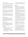
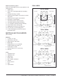
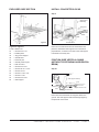
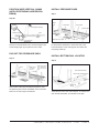
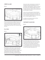
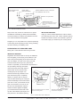
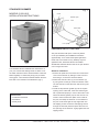
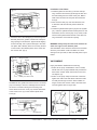
CENTURY
OVAL Pools
ASSEMBLY INSTRUCTIONS
ASSEMBLY INSTRUCTIONS
CENTURY -
OVAL -
page
1
Installation Instructions
3.Do not attempt to lift the heavy boxes by yourself. To
HOW TO USE THESE INSTRUCTIONS
Be sure to read these instructions completely before
reduce the possibility of personal injury, have someone help you move heavy boxes (pool wall, liner, etc.).
beginning the installation of your pool. ATTENTION:
warning
Always use these assembly instructions to install
1.Your pool must be level within 2-3 cm all around.
your swimming pool. Ignore any English instructions
An unlevel pool may cause excessive stress on
included with the pool, as the size will be in inches, etc.
the pool frame. A pool which is not level may
ATTENTION: Check the pool parts with the English
cause a lot of pressure on the frame. This may
parts lists.
result in pool failure which could cause serious
personal injury.
These are installation instructions for the installation of
2.Your pool must be on undisturbed soil, preferably
several sizes of round pools. Use the pool parts list and
filtered sand. Filled up sand, sudden slopes within
extensive illustrations to identify your pool parts; then
15 cm or the water runoff may cause a cave in of
read these instructions and follow the steps that pertain
the subsoil. This could cause pool failure and may
to your pool assembly.
cause personal injury.
3.Always install the Warning Sign. The decal is
Doughboy cannot be held liable for damage caused by
designed to warn you, your friends and loved ones
careless or improper installation. Your warranty is void
that your pool is to be used for swimming and wad-
if the pool assembly and installation instructions are
ing only. Do not allow any form of horseplay in or
not followed exactly, or if the pool design is altered in
around the pool. Failure to follow this warning can
any way.
lead to severe personal injury. Read the “Safety
First” booklet (in English).
Contracted Installation
4.Use stabilised sand as a pool cove. Common sand
Doughboy is not affiliated with any professional pool
can easily erode and allow the pool liner to rupture
installers and cannot assume any responsibility for
which may cause pool failure or personal injury.
installation mistakes made by the homeowner. If
5.Secure your pool when not in use. Ladders and
the pool is installed by others, please supervise the
gates should be secured to reduce the possibility
installation and make sure that the correct installation
of unauthorised entry and possible serious
method is applied.
accidents.
6.Always repair liner leaks. Continued leakage
Change of pool design
between the pool wall and liner can cause wall
Doughboy expressly reserves the right to change or
damage to the wall which eventually may result
modify the design and instruction during the course of
in pool wall failure. This could result in personal
our manufacturing procedures, without incurring any
obligation or liability to reapply such modifications on
products previously or currently sold.
injury.
7.To reduce the risk of possible electrical shock,
never install your pool under overhead wires.
8.Do not alter your pool as this may cause pool fail-
CAUTIONS
ure. Your warranty is void if the pool is altered.
1.Do not attempt to install pool wall on windy days.
9.Do not install a diving board, pool slide or any
An unsupported pool wall can easily blow down and
other recreational accessories for use during div-
may thus cause personal injury.
ing, sliding or jumping into your pool.
2.When assembling your pool, keep the parts not
10.ATTENTION: Do not install the pool liner at tem-
currently used in an area out of the way. Unpacked
peratures under 16ºC. At lower temperatures the
parts are easily tripped over and may be damaged
liner’s elasticity is too limited for proper installation.
or cause personal injury.
ASSEMBLY INSTRUCTIONS
CENTURY -
OVAL -
page
2
POOL SIZES
Where to position my pool?
Before you start building your pool, pay attention to the
6,10 x 3,60m
following points:
1.Garden fence.
2.Trees, roots, overhanging branches and falling
pool radius
clearance radius
leaves.
3. Underground wiring or cables.
4.Position pool with regard to sun terrace or sunken 301
sitting area.
301
177
177
5.Position pool with regard to the sunshine.
6. Supervision of small children.
360
210
centerline
244
7. Convenient location of filter and pump.
string line
maatlijn
8. Convenient electrical outlet for the pump
9. 2 or 3 people for assistance during assembly.
10.Do not build in case of strong wind.
11. Walking space around your pool (60 cm).
310
stake
side support
support clearance
12.Put your pool on a level underground.
7,30 x 3,60m
13.In case of building the pool into the ground: groundwater level.
clearance radius
pool radius
MATERIALS AND TOOLS NEEDED
(Not included)
406
185
Materials:
360
406
177
177
1. 12 nails, 4 cm long
centerline
366
2. Patio blocks, 1 per stud
177
3. Roller masonry or kite string
245
string line
177
310
4. Binder clips
5.Straight board, 5 x 10 cm diameter
stake
side support
(Length, please refer to Step 1)
support clearance
6. Scotch tape 5 cm wide
8,50 x 4,90m
7. Wooden stake 5 x 5 cm, 50 cm long
8. Sub-liner
pool radius
clearance radius
Tools:
1. Carpenter’s level
436
2. Carpenter’s saw
3. Fibre tip pen
251
4. Stanley knife
490
436
237
237
366
5. Star + regular screwdriver
237
6. Hammer
274
centerline
string line
237
7. Shovel / barrow
8. Rake
370
stake
side support
9. Tape measure
support clearance
ASSEMBLY INSTRUCTIONS
CENTURY -
OVAL -
page
3
POOL LAYOUT
STAKES AND STRING LINES
Step 1
Step 3
string line
support width
level tops
string line
string line
centerline
of pool
clearance radius
side support
excavations
(see step 4)
string line locations
By means of the plan you determine the layout of the
Locate 4 stakes C, D, E and F in accordance with indi-
clearance. Locate stakes A and B (in accordance with
cated measures of the plan of your pool. Attach strings
indicated dimensions) and make from there 2 circles
between C and D, then E and F. Now mark the assem-
for the clearance.
bled side supports, as indicated on the plan.
GROUND LEVELING
SIDE SUPPORT EXCAVATIONS
Step 2
Step 4
5 x 10 cm leveling board
3,6 m wide pool = 2,45 m long
string line locations
drill hole
nail
stake
level
side area
level area
clearance
radius
Clear and level the pool area in the clearance as indicat-
Carefully dig out side support trenches following
ed. For a firm ground it is better to remove high points
dimensions above.
than filling in low spots. Remove sods, stones, roots and
other objects that could puncture the liner. The entire
assembled pool framework must sit on flat ground.
ASSEMBLY INSTRUCTIONS
CENTURY -
OVAL -
page
4
EXPLODED SIDE SECTION
INSTALL CONCRETE BLOCKS
Step 5
side support
assembly
string line
Fill with
concrete
skid
plate
horizontal
beam
level
concrete block
Figure A
Legend for Figure A
Place two concrete blocks into the excavations and
11/a/b= Bottom rail
place the assembled side supports into each trench
16
= Screws #10 x 1/2"
perpendicular, so that the front side of the side support
34
= Antiskid plate
is situated to the tautly wire.
35
= Top ground support
36
= Vertical base
37
= Pressure pad
38
= Vertical pressure pad
39
= Rail connector
40 = Screws #12 x 3/4"
41
= Screws 3/8-16 x 3-1/2"
42
= Screws 3/8-16
43
= Screws 1/4-20 x 1/2"
44
= Screws 1/4-20
45
= Screws #10 x 3/8"
46
= Side support
POSITION SIDE VERTICAL SHIMS
(WITHOUT PROTRUDING HORIZONTAL
BEAM)
Step 5a
slope
side support assembly
level
fill with
concrete
firm
undisturbed
earth
slope downward
square wood of 2 cm
concrete blocks
Place the horizontal beams two degrees tilted in the
ground. The side supports will stand straight again by
the pressure of the water.
ASSEMBLY INSTRUCTIONS
CENTURY -
OVAL -
page
5
POSITION SIDE VERTICAL SHIMS
(WITH PROTRUDING HORIZONTAL
BEAM)
INSTALL PRESSURE PADS
Step 7
Step 5b
# 10 Screws
Begin
here
slope
# 12 Screws
# 12 Screws
side support assembly
pressure pad
level
fill with concrete
firm
undisturbed
earth
Work from left to right
concrete blocks
notch out
Place the horizontal beam level. The side supports will
Fix the pressure pads both to each other and to the
stand straight again by the pressure of the water.
horizontal beams of the side supports and make sure
everything is filled up.
DIG OUT FOR PRESSURE PADS
INSTALL BOTTOM RAIL LOCATOR
Step 6
Step 8
62 cm
side support
assembly
2,5 cm
Make scribes approx.
2,5 cm deep at the
spot of the pressure
pads
side vertical assembly
61 cm
bottom side rails stamped “S”
pressure
pad
5 cm
bottom rail
locator
Remove dirt at the spot of the pressure pads so that
the pressure pads can be assembled on the horizontal
beams of the side support assemblies.
Assemble the bottom side rails stamped “S” between the
side vertical assemblies, as indicated on the plan.
ASSEMBLY INSTRUCTIONS
CENTURY -
OVAL -
page
6
INSTALL BOTTOM RAILS
NOTE: Place enough sifted earth into the pool area to
cover the pressure pads. With a high groundwater level
Step 9
(in ground pool) we advise to install a concrete floor.
Only for 16" and 21" pools,
stamped TR (4 pcs)
Bottom rails stamped 12",
16", 18" and 21"
INSTALL WALL JOINTS
Step 11
Level
Bottom rail
connector
Bottom rails
Screw
Optional sunk patio
blocks
Bolt
Slide the bottom rails into the vertical end caps, groove
up (see plan). Start on opposite sides of the side vertical
assemblies with the end rails stamped with 12". When
The wall joints overlap (see plan). If joint piece doesn't
the bottom condition is not optimal, place a patio block
slide on easily, correct the side supports until the joints
under every vertical end cap (sunk on bottom level for
fit perfectly. See to it that the round shape is preserved.
extra certainty).
Connect the wall joints by means of the bolts and
screws included in the packaging. Attention: the
screwhead must be on the inside of the pool. Smooth
INSTALL WALL
the screws. Fix the protective strip with tape.
Step 10
INSTALL VERTICALS & END CAPS
steel pool wall
Step 12
large dia
stabilizer rail
large and small
stabilizer rails telescoped
around ends of
pool only
stabilizer rails
sifted
earth
vertical end cap
start wall at center of vertical
end cap
Remove steel pool wall from carton. Note ‘Up’ arrow on
wall. Determine starting point of wall from preliminary
vertical
planning, depending on the place of the pump and the
filter. The skimmer opening will be at the inside end of
the wall coil. Always start with the center of a vertical
Install the verticals, so that the screw aperture is at
end cap. Always uncoil 1,5 m and insert bottom edge
the front side on top of the vertical. The construction
into groove in bottom rails. When the ends of the pool
is connect by screws. Position vertical end cap over
do not connect completely, correct this by telescope the
vertical (see plan). A drop of oil on the screws
bottom rail more or less into the vertical end caps.
facilitates your work.
ASSEMBLY INSTRUCTIONS
CENTURY -
OVAL -
page
7
STEEL TOP RAIL / END SECTION
INSTALL TOP RAILS + HOLES CHART
FOR TOP RAILS
(CENTURY 6,10 x 3,60 / 7,30 x 3,60)
Step 13a
There are two different joints, a straight and a round
joint. A, B, C straight / D round (see fig. 13 A).
Four screws connect the top rails with the vertical end
caps. Screw the screws in the right holes of the top rails
and vertical end caps.
Follow the measures of the holes chart.
Holes with numbers 1 and 3 are of the inside of the pool.
Holes with numbers 2 and 4 are of the outside of the
pool.
Figure 13A
Figure B
Legend for Figure B
Mounting end sections
1 = Covering panel
11 = Bottom rail
4 = Screws
17 = Screw
5 = Stabilising rail (large)
19 = Vertical
6 = Stabilising rail (small)
20 = Liner
7 = End cap
28 = Wall
8 = Connector
29 = Bolt
9 = Cover
30 = Nut
10 =Plastic profile
31 =Protective strip
Joint A 3,60
Hole chart for ovale pools
Joint A Hole 1 – Top Rail C
Hole 1 – End cap S3
Hole 2 – Top Rail 18/24
Hole 2 – End cap
S3
Hole 3 – Top Rail C
Hole 3 – End cap S3
Hole 4 – Top Rail 18/24
Hole 4 – End cap
S3
ASSEMBLY INSTRUCTIONS
CENTURY -
Joint B 3,60
Joint B
C
12
C
12
C
12
C
12 OVAL -
page
8
INSTALL TOP RAILS + HOLES CHART
FOR TOP RAILS
(CENTURY 8,50 x 4,90)
COVE
Step 14
Step 13b
15cm
Cove
10cm
There are two different joints, a straight and a round
joint. A, B, C straight / D round (see fig. 13 B).
Four screws connect the top rails with the vertical end
caps. Screw the screws in the right holes of the top rails
Warning: Use sifted
earth, so that the cove
can not crumble.
and vertical end caps.
Follow the measures of the holes chart.
Holes with numbers 1 and 3 are of the inside of the pool.
Important step: Make on the inside of the steel wall a
Holes with numbers 2 and 4 are of the outside of the
slant elevation of sifted earth of around 15 cm high and
pool.
wide. This is a vital structural element that prevents
water pressure from forcing the pool liner out under the
Figure 13B
bottom rail.
LINER SEAM POSITIONING
Step 15
Please check if the article number of the
liner corresponds with the article number
on the packaging.
Liner / inside
Side seam
Water side
Liner / inside
Joint A 4,90
Joint B 4,90
Item number
Bottom seam
Check the pool floor again for stones, glass and other
sharp objects. Fill in all footprints and other unevenness
Hole chart for ovale pools
Verbindung A Hole 1 – Top rail C
Hole 1 – End cap S3
Hole 2 – Top rail
18/24
Hole 2 – End cap
S3
Hole 3 – Top rail C
Hole 3 – End cap S3
Hole 4 – Top rail 18/24
Hole 4 – End cap
S3
on pool floor. As floor sealing and extra protection of your
Verbindung B
C
16
C
16
C
16
C
16 liner it is advisable to cover the floor with water-resistant
underlay, that you can fasten with tape to the underside
of the steel wall. Now place the liner on the top rail and
check as indicated.
Note: The embossed side of the liner will be the water
side.
ASSEMBLY
M OI N
NS
TA
TR
GU
E CI TNI SOTNRSU C T
E INET U
CR
EY
N T- U O
R VY A -L P- A pGaI g
Ne
A 9
1
STRETCH LINER
into the pool until the desired tautness is achieved and
re-clamp the binder clips. Remember that you are
Step 16
monitoring a minimum tightness of the liner over rail that
will control the liner seating itself against the pool floor
and up the side with no wrinkles. When the water (5 cm)
bottom liner seam
is covering the pool floor, the liner on the pool floor must
be without pleats and wrinkles.
If this occurs, pull and lift the liner wall just enough to
stretch out wrinkles or pleats by the water weight. There
should be just barely enough tension on the liner, until
the floor is filled with approximately 20 cm water and the
liner is connected against the metal wall.
The clamps can be bought at several tool shops
(Preferably use synthetic clamps).
Work in both directions with unfolding the liner and drape
it over the top rail and down the sides for about 60 cm.
CONTINUE FILLING POOL
The liner should be about 40 cm above the pool floor
in the center only. The bottom edge seam of the liner
Step 18
should be inside the pool about 30 cm from the top rails
(see plan).
water level
FILL POOL
Step 17
clamp
After the pool is filled, the bottom liner seam of the
liner must be totally around in the pool must be close
to crossing of the bottom wall. Do not worry about the
strength of the liner, the strength is calculated on
garden hose
cardboard
binder clips
1,5 x the original size. When the bottom liner seam is
not on the right place, there is a chance that you have
not enough liner left to place on the top border, so that
Before filling the swimming pool, hold the liner in place
you have to start again with placing the liner.
by attaching two binder clips over folded cardboard on
the underside of each top rail. Because of the water
weight, the liner will be stretched with no wrinkles. Check
during filling the pool the liner for extreme tautness.
Binder clips do not self-release, so release binder clips
with extreme tautness and allow the liner to feed back
A S S E M B L Y MI O
NN
STA
RG
UE
C TI INOSNTSR U
CC
E TN ITEU R
CY
E N- T O
UV
RA
Y L - - P pA aGgI N
e A1 0
1
PROCEDURE TO ATTACH LINER
Now assemble the skimmer, inlet and filter as indicated
on the special enclosed instruction. Then fill the pool to
Step 19
the indicated level on the skimmer plate.
fold back liner from 3 top rails
top connector
top rail
stabilizer rails
vertical end
cap
With the help of two or three people, raise and hold the
liner up from any three top rail sections. Be careful and
never allow the liner to fall back into the pool. When 1
man is holding the liner, the other folds back the vertical
end caps, the top rails and top connectors from three top
rails (see plan).
INSTALL COPING AND
STABILIZER RAILS
Step 20
small dia. stabilizer
large dia. stabilizer
plastic coping
liner
return hem
pool wall
Make a return hem as illustrated and smooth the liner
against the wall (see plan). Place the coping over the
liner and the stabilizer rails over the coping after pushing
it together about 15 cm. Replace all parts removed in
step 19 and repeat the same steps for all 3 top rails until
you assembled the entire pool.
A S S E M B L Y MI O
NN
STA
RG
UE
C TI INOSNTSR UC CE TNI TEU C
RE
Y N- T O
UR
VA
Y L- -Pp
A aG gI N
e A1 1
SUPPLEMENTARY INSTRUCTIONS
FOR BUILDING A POOL IN THE
GROUND
To avoid that material rolls onto the site where the pool
is to be constructed, the location where the pool is to
INSTALLATION OF SKIMMER AND INLET
be constructed must be in the most elevated part of the
The skimmer and the inlet have to be installed before
garden. The surrounding landscape should be lower
the pool is filled with water and before the pool is filled
than the pool. Attention, the water level of the pool
up with stabilized sand. During the installation of the
should also be above the groundwater level during the
internal lining and the skimmer, the lead through for the
winter (water level 15 cm below the inlet).
skimmer may not be created yet. Install the inlet and
The specific installation such as seen in Figure 2 serves
gasket. Remove the internal lining from the inlet opening
only as a reference and is not representative for all pool
and install the valve delivered with the skimmer.
installations. The parts which may need special materi-
PLUMBER’S WORK
als are the lighting and chloride installations.
In order to prevent that the hoses move up and down,
EXCAVATING
you should connect the skimmer and the inlet with rigid
1. The circumference of the excavation is the same as
PVC to the filter (Figure 2). If you are using flexpipe, you
the size of the pool plus 60 cm around the whole
need to make sure that this pipe is not bent, before you
pool. Determine the size of the excavation pertaining
fill up the rest of the pool. Install the pump as closely as
to the size of the pool and use for this the exten-
possible to the pool in connection with the drawing in of
sive installation instruction delivered with the pool.
the pump. If this pump is a Doughboy Pool Powerpack,
(Attention, the soil should be at least 15 cm white
then you should place it below the water level.
sand or stabilized sand; on top of that we recommend
FILLING THE POOL
a layer of styrodur or a protective blanket.)
2. The depth of the excavation is dependent on the
First fill the pool with water up to approximately 5 cm
height of the pool and desired terrace. Use the size
away from the top edge. This procedure is absolutely
such as seen in Figure 1 to calculate how deep the
necessary to absorb the pressure performed on the wall
excavation should be.
during the application of stabilized sand. Ff the pool
3. After the pool is excavated, the frame and the wall
should be installed according to the installation ins-
is not filled completely with water, this can cause pool
failure.
truction delivered with the pool.
SHUTTERING
We recommend that you apply a shuttering around the
skimmer before the pool is filled up.A space around the
skimmer and any other accessories offer you the possiFigure 2
Specific installation
Cover panel
60 cm working space
around the pool
12-15 cm
Fill the pool up to 5 cm below the top edge
Grade
(2 cm per meter)
FIG. 1 - CONSTRUCTION PROVISIONS WHEN A POOL IS EXCAVATED
A S S E M B L Y MI O
NN
STA
RG
UE
C TI INOSNTSR U
CC
E TN ITEU R
CY
E N- T O
UV
RA
Y L - - P pA aGgI N
e A1 2
1
Feed towards pump
gate of filter
Check valve
(Recommended)
Space between the top of the pool
and stabilizer sand 22 cm
Retour towards
return gate
filter
Grade 2 cm per meter
Stabilisierter Sand
Füllen Sie erst das Schwimmbecken,
bevor Sie den stabilisierten Sand
auffüllen.
Valve
(Recommended)
PVC tube and fixtures
FIG. 2 SPECIFIC INSTALLATION
bility to have easy access for maintenance or repairs.
IMPORTANT MESSAGE:
ATTENTION: If the filling up takes place immediately
Piling up of loose material between the mixture and the
around the skimmer, it shall be more difficult in the futu-
poor wall may push in the wall. If extra material is placed
re to check the skimmer during leaks.
between the mixture and the cover material to get this at
the correct height, you should only use a sturdy mortar.
Doughboy is in no way liable for the expenses pertaining
to the finding and/or repairing of leaks, cutting, breaking
off and/or removing of stabilizing sand.
PREPARATION OF STABILIZER SAND
Mixing ratio 1 m3 fluvial sand with 125 kg concrete.
IMPORTANT WARNING:
Regardless the method used for the way the stabilized
sand is applied, you should pay close attention to the
wall of the pool during filling to be sure that the wall
does not collapse. If a dent occurs in the pool wall,
someone should enter the pool to push it back.
If this is not possible, you should lower the pressure to
the pool wall by removing the mixture
used to fill up the pool locally again so
Without patio blocks
With patio blocks
that the dent can be removed. Then
carefully fill up the pool again. You
should at all times pay attention to the
pool wall until the pool is completely
filled up. To prevent rust on the pool
wall, the water streaming out of the pool
should immediately be removed from the
pool wall. For this you should let the top
layer run off at least 2 cm such as can
Stabilized sand
be seen from the illustration. After the
mixture has been applied completely,
you should lower the water level to the
top line of the skimmer opening and cut
Keep the stabilized sand 5 cm below
the screw of the guard
Top of the
patio block
Stabilized sand
Keep the patio blocks 5 cm below
the screw of the guard
away the liner in the skimmer opening.
FIG.3 - WITH/WITOUT PATIO BLOCKS
A S S E M B L Y MI O
NN
STA
RG
UE
C TI INOSNTSR U
CC
E TN ITEU R
CY
E N- T O
UV
RA
Y L - - P pA aGgI N
e A1 3
1
Standard SKIMMER
Fig. 1
Standard Skimmer
MODELS 5-2091-015
INSTALLATION INSTRUCTIONS
Cover
Outside pool
Inlet
Sand filter
Pool pump
PREPARATION OF THE POOL
The pool should be built up the correct way based
on the pool assembly and installation instructions.
Approximately 70 cm water should press against the
metal wall, so that there isn’t any elasticity anymore
against the liner, before the skimmer is installed.
ATTENTION: After the skimmer hole is cut open the liner
can no longer be moved.
Your standard skimmer facilitates the maintenance of
your pool. Leaves and floating refuse are taken out of
Skimmer installation
the water and enter into the skimmer basket. Clean the
1. Remove all parts from the carton box. Remove the
basket regularly to continuously keep your pool clean
and hygienic. The numbers indicated between the brackets refer to the numbers of the illustration (Fig 7).
cover of the skimmer by sliding it to the front and
then lifting is; remove the skimmer basket.
2. Fasten the skimmer valve (7) to the skimmer (3)
by using three screws (8). Push the skimmer valve
into the skimmer so that the foam side is facing the
bottom.
3. Install the top skimmer gasket (9) into the square
opening of the metal wall; make sure that the gasket is positioned properly in front of the holes. Then
Needed tools
fasten the bottom gasket (10) into the vacuum con-
• Crosshead screwdriver
nection. Place the skimmer plate on the inside of
• Screwdriver
the pool, and keep the skimmer on the outside of
• Stanley knife
the pool. First screw tight the top angles with two
self tapping screws. Press the self tapping screws
through the skimmer plate and press the liner into
the openings of the skimmer. Lightly tighten the self
tapping screws.
A S S E M B L Y MI O
NN
STA
RG
UE
C TI INOSNTSR U
CC
E TN ITEU R
CY
E N- T O
UV
RA
Y L - - P pA aGgI N
e A1 4
1
Installation inlet fixture
Fig. 2
1. Install the gasket of the inlet (17) into the wall opening. Insert the inlet fixture (18) through the liner and
Inside pool
Skimmer
plate
the wall starting from the inside of the pool. Make a
small notch into the liner and press the inlet fixture
through.
2. Now screw the inlet (16) onto the inlet fixture; turn
it clockwise until the inlet end points towards the
Skimmer
valve
Suction connection for
cleaning pool
bottom.
3. Install the eyeball inserted piece (20) into the eyeball
(21). Insert the eyeball with the inserted piece into the
inlet fixture, turn the closure (22) on top of that; make
sure that the eyeball location stands in the water run-
4. Screw the rest of the self tapping screws through the
ning off direction of the skimmer opening
skimmer plate, liner, gaskets, wall and the corresponding openings in the skimmer. Tighten all self tapping
screws manually; this to prevent damage to the skim-
WARNING: Always keep the water level between the
mer plate. With a Stanley knife now cut away the liner
water level signs on the skimmer plate.
on the inside of the skimmer plate; do the same with
After installation of the skimmer check if there are leaks
the vacuum inlet. (Fig 4)
when the pool is filled. Continuous leaks can cause
damage to the pool wall, so that eventually there is pool
failure.
Fig. 3
Self tapping
screw
Skimmer plate
Gasket
VACUUMING
Empty the skimmer basket before suctioning.
1. Switch off the pump. Assemble the vacuum nozzle,
handle and hose. A proper flexible hose provides the
best suction results. Attach the free end to the vacuum adaptor (13).
Gasket
2. Switch on the pump. Keep the free end of the hose
Inside pool wall & liner
against the outlet of the inlet fixture. Because of this
air shall pass through the hose. When bubbles no
ATTENTION: The gasket around the vacuum connection
longer exit from the vacuum nozzle, all air has been
(10) is necessary to ensure a watertight closure around
removed (please refer to Figure 5/6).
the vacuum connection during the suctioning off of
water. Attach the suction cover (12) and the attachment
of the suction cover (11) to the skimmer plate with a
screw (8).
Fig. 4
Cutting away
liner
Skimmer
opening
Suction connection
Outside pool
Fig. 5
Fig. 6
A S S E M B L Y MI O
NN
STA
RG
UE
C TI INOSNTSR U
CC
E TN ITEU R
CY
E N- T O
UV
RA
Y L - - P pA aGgI N
e A1 5
1
Warning: Never try to install the cover in a suctioning
Lid
position if the pump is switched on. The cover might
Vacuum
adaptor
suddenly be pulled down due to the strong suction of the
pump. You may suffer personal injury to your hands or
fingers.
5. When the cover is in place, you can switch on the
Suction cover
Fig. 7
pump and put into operation the suction of the pool
floor.
6. When you are finished suctioning, you have to switch
3. Fold the cover of the vacuum opening (12) so that
off the pump. Remove the vacuum hose with the
it points towards the bottom. Insert the tapering end
vacuum adaptor connected to it from the pool. Clean
of the vacuum adaptor with the hose attached into
the skimmer basket and your filter. Relocate the cover
the opening by making a turning movement (Fig. 7).
to the original position on the top of the skimmer.
4. The cover (2) has two functions. In the normal
position is covers the top of the filter. During suc-
Switch on the pump to resume the normal operation
of the pump.
tion, this same cover becomes the closing plate for
suctioning; make sure that the pump is in the OFF
position. Remove the cover, turn it 90º and let it
drop to the inside and place it above the basket.
Make sure that there is no air under the cover.
Trapped air shall make the cover rise.
STANDARD SKIMMER PARTS
No. Article
Amt Description
1 1300-1002
1
Skimmer basket
2 1121-1506
1
Skimmer cover
3 1121-1864
1
Skimmer
4 360-1794
1
Sticker
5 1121-1358
1
Skimmer valve
6 340-1600
1
Attachment skimmer valve
7 1107-1275
1
Skimmer valve plus attachment
8 330-1008
4
Screws
9 307-1029
1
Top of gasket
10 307-1030
1
Bottom of gasket
11 340-2089
1
Attachment suction cover
12 348-1028
1
Suction cover
13 340-1590
1
Water suction adaptor
14 330-1004
15
Screws
15 340-2090
1
Skimmer plate
16 340-1591
1
Inlet
17 307-1031
1Gasket inlet
18 340-1592
1
Inlet adaptor
19 340-1594
1
Closure disk
20 340-1595
1
Eyeball attachment
21 348-1027
1
Eyeball
22 340-1593
1
Closure for the inlet
23 360-2023
1
Operating Instructions Label
A S S E M B L Y MI O
NN
STA
RG
UE
C TI INOSNTSR U
CC
E TN ITEU R
CY
E N- T O
UV
RA
Y L - - P pA aGgI N
e A1 6
1
PREPARING FOR WINTER
When the swimming season is over, you have to follow
the instructions to get your pool ready for winter.
ATTENTION! Do not remove all the water from your
pool and also do not remove the liner. An empty pool can
namely cause pool failure.
Lower the water level
- Lower the water level in your pool so that it is approximately 6” (15 cm) below the inlet fixture; maintain this
water level by checking it regularly.
- If you have a skimmer, then absolutely do not let the
water freeze in the skimmer but rather drain this water.
Check all screws and connections
Anti-freeze liquid
- Make sure that all installation connections and parts
This liquid can be used without problems in combination
are positioned correctly and that the pool wall is not
with chloride products. Upon finding algae present first
moved away from the bottom rails.
apply a ‘shock treatment.’ The liquid should be, dis-
- Make also sure that all connections are water tight.
Check if there is rust
solved in a pail of water, spread out equally across the
water surface. During the dosage the pump should be
- Correct all damages or rust spots with a varnish stick.
in operation. The dosage is 0.5 litres per 10 m3, after
approximately four weeks 0.3 litres per 10 m3.
Check the liner (interior tarpaulin)
- Make sure that the top of the liner is still overhanging
ATTENTION! Never mix the liquid with other pool che-
the pool wall attached to the plastic edge. Do not
micals or chemicals and always add the product to
remove the liner from your pool. Upon removal of the
water, never the other way around.
liner of the pool the warrantee becomes void. Do not
pump dry all the water from the pool during the winter.
If you do not adhere closely to the winter instructions,
the warrantee of your pool may become void. Thus care-
Leaks found
fully adhere to all instructions for maintaining your pool
- Make sure that there aren’t any leaks in the liner.
during the winter.
Leaks during the winter can cause serious damages to
your pool.
Pool accessories
- Remove all pool accessories from the pool, including
the ladder. Leave the skimmer and inlet fixture in
place.
The filter
- Disconnect the filter from your pool and follow the filter
instructions for maintaining the filter during the winter.
Clean the pump and the filter for the winter (frost free).
A S S E M B L Y MI O
NN
STA
RG
UE
C TI INOSNTSR U
CC
E TN ITEU R
CY
E N- T O
UV
RA
Y L - - P pA aGgI N
e A1 7
1