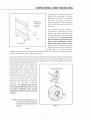
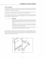
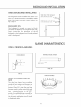
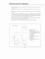
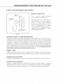
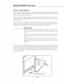
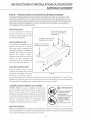
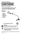
1
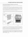
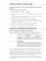
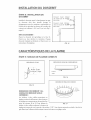
PERFECT
h EATs'
PROFESSIONAL 30" SELF CLEAN
RANGE
(nstallat(on
MODELS
[] RGSC-305SS
[] RGSC-30SBK
[] RGSC-30SWT
Manual
NOTE TO [NSTALLER
The DCS Professional series of Ranges and Cooktops are designed with a large number of features available
in a multitude of different combinations.
For your convenience,product questions can be answered by a DCS Customer Service Representative by
phone: 1-888-281-5698,or Fax:714-372-7004,or email: [email protected]
or by mail:
DCS
Attention: Customer Service
5800 Skylab Road
Huntington Beach,CA92547
www.dcsappliances.com
WARNING
If the information
explosion
death,
in this manual
may result
causing
is not followed
property
damage,
exactly,
personal
a fire or
injury
or
PRECAUTION
Do not store or use gasoline
the vicinity
or other flammable
vapors and liquids
in
of this or any other @pliance,
FOR YOUR SAFETY
If you smell gas:
n Do not try to light any appliance,
n Do not touch any electrical
switch;
do not use any phone in your
building,
@ Immediately
call your gas supplier from a neighbor's
the gas supplier's
Installation
and service must
be performed
service agency or the gas supplier,
PLEASE RETAIN THIS MANUAL
phone, Follow
instructions,
FOR FUTURE REFERENCE,
by a qualified
installer,
TABLE OF CONTENTS
UNPACKING AND HANDLING
Step 3: Unpacking,
Moving
and Phdng
the Range ................................................................................
7-8
ELECTRICAL/GAS CONNECTIONS
Step 4: HectricaH Connections .............................................................................................................................
9
Step S: Gas ..................................................................................................................................................................
9
CLEANING EXTERIORSURFACES
Step 1O:CHeaning Exterior Surfaces ...............................................................................................................
13
INSTALLER FINAL CHECKLIST .........................................................................................................................
14
WARRANTY .......................................................................................................................................................................
1s
SERVICE .................................................................................................................................................................................
16
PLANNING THE INSTALLATION
IMPORTANT INSTALLATION INFORMATION
The RGSC-305 is tested
in accordance
with
ANSI Z21.1 Standard
for Household
Cooking
Gas
App[hnces.
The
range
ventilation
attention
must
be installed
requirements,
should
be paid
codes.
To eHiminate
above
the surface
in conjunction
page
to the
hood
risk of burns
units
should
with
4). Due to the
and
duct
work
or fire by reaching
over
overhead
high
heat
instaHHation
heated
vent
to ensure
surface
hood.
capacity
of this
it meets
units, cabinet
(See
Step
unit,
I for
particuHar
[oca[ building
storage
[ocated
be avoided.
All range models with less than a 12"clearance
the range, require the installation
Wa[[Mount
a suitable
professiona[
between combustable
material and the back edge of
of one of the two offered Wall Mount Backguards.
Fuji
Backguard
(ModeINo.
BGS-3030)
28-1/8"
Wall Mount
FIG. 1
Check local building
electrical
FIG. 2
codes for the proper method of range installation.
connections,
and grounding
must comply with all applicable
Local codes vary. Installation,
codes. In the absence of local
codes, the range / cooktop should be installed in accordance with the National
Z223.1q 988 and National Electrical Code ANSI/NFPA 70-1990.
Fuel Gas Code ANSI
Be sure that the unit being installed is set up for the kind of gas being used. The gas range is shipped
from the factory
set and adjusted
ordered.
that
proceeding
Verify
further.
the
range
for Natural Gas or LP (propane), depending
is compatible
with
the gas at the
on the specific
installation
Return range to dealer if the unit is not set for site gas supply.
site
mode[
before
PLANNING THE INSTALLATION
Recommended
Install
Installation
components
Instruction
in the following
a. Vent Hood
b. gackguard
1. Locate and [eve[ range according
(when
using
BGS-3030
order:
System
c. Range
to Range installation
instructions.
2. Measure distance from floor to top of isHand trim on range adding
3.Transfer this measurement
to the waHL This wH[ mark the bottom
]/8" for backguard
6. Follow backguard
installation
instaHHation instructions
instructions
7. Connect gas and electric connections
A suitable exhaust
the minimum
This is the minimum
height
to install[ vent hood.
to install backguard.
and slide range into position.
VENTILATION
STEP 1: VENTILATION
cHearance.
of your backguard.
4. From this [ine measure 28-1/8" up wall[ to mark top of 30" backguard.
that the bottom of your vent hood can be instaHHed.
5. FoHHowvent hood manufacturer's
Backguard)
REQUIREMENTS
REQUIREMENTS
hood must be installed above the range / cooktop.
blower capacity recommended
VENTILATION
UNIT
The following
chart indicates
for hood ventilation.
STANDARD COUNTER
INSTALLATION
RECOMMENDATIONS
HOOD
(24" Deep x Unit Width)
BLOWER
600 CFM (rain.)
ISLAND
INSTALLATION
RECOMMENDATIONS
(30" Deep x 36" at Bottom)-"
600 CFM (rain.)
CAUTION:
Ventilation
hoods and blowers are designed for use with single wall ducting.
However, some local building
ducting. Consult local buiMing
codes or inspectors may require double wall
codes and/or local agencies, before starting, to
ensure that hood and duct installation
Hood blower
household
speeds
should
For best smoke elimination,
maximum
combustible
be variable
air when maximum
ventilation
to reduce
noise and loss of heated
the lower edge of the hood should
materials (i.e.a wood covering)
of ventilation
particularly important for tightly
contractor should be consulted.
or air conditioned
is not required.
of 36" above the range cooking
Due to a high volume
will meet local requirements.
be installed
surface (See Fig. 3, page 5).
it must be a minimum
air, a source of outside
sealed and insulated
of 30" to a
contains
of 36" above the cooking
replacement
homes.
a minimum
If the hood
air is recommended.
A reputable
heating
any
surface.
This is
and ventilating
CABINET PREPARATION
STEP 2: CABmNET PREPARATmON
1. The range is a free standing unit. Hfthe unit is to be placed adjacent to cabinets, the clearances
shown in Fig. 3 are required. The same cHearances appHy to isHand instaHHations.
2. The range can be pHaced in various positions with respect to the cabinet front, with the front
either flush or projecting, depending on the countertop
depth (See Fig. 5, page 6).
00
L !
35-3/8"max.for levelcounter,
3&3/4" max.with range
levelinglegsfully extended
A)
7q/2"
m 18"mJn.
C) 3"
"As definedin the
"NationalFuelGasCode"
(ANSIZ223J,latestedition).
D)
Therangeheight[sadjustable.The[eve[of the
rangetop must beat the same[eve[orabovethec0untertoplevel.
FIG. 3
Flex Line
to Range
2" Maximum
Protrusion from Wall
for Gas Supply
FIG. 4
13"max.
E) 4-1/2" (gas)
F) 11"(electrkal)
"'-..
CABINET PREPARATION
3. The gas and eHectrkaH suppHy shouHd be within the zones shown in Fig.3 & Fig.4, page 5.
4. The maximum
depth of over head cabinets
instaHHedon either side of the hood is 13".
5. Any openings
in the waHHbehind the range and in the floor under the range must be seamed.
6. When there is Hessthan a 12" cHearance between combustibHe materhH and the back edge of
the range, (above the cooking surface) a DCS gackguard must be instaHHed (see Fig. 5). The
range comes equipped with HsHandTrim as standard. Fig.5 indicates the space required for each
type of backguard.
7. AHways keep the appHhnce area dear and free from combustibHe
flammabHe vapors and Hiquids.
8. Do not obstruct
the flow of combustion
materiaHs, gasoHine and other
and ventiHation air to the unit.
Dimensions:
i
joO
000
O0
O,s
B
29-7/8"
B) 39 3/4"- 37"
E} 27-1/2"
F) 28-1/8"fullbackguacd
A)
\\\\\\\\\\_-_%\_\\\\\\\\X_
XX\\X\%\X\\N
\\\_
\\\\\\\X%\\\\%
G/ 10-1/8" 10wbackguard
H) 2"Bland tc[m
E
i) 14/J6"
J) 30"
m 44-5/8"
L) 36"min,tocombustibles
M) 24-1/4"
N) 264/4"
o) 12"rain.tocombustibles
'
0"clearance
0" clearance
FIG. 5
UNPACKING AND HANDLING
STEP 3: UNPACKING, MOVING
AND PLACING THE RANGE
CAUTION:
PROPER
EQUIPMENT
AND
ADEQUATE MANPO WERMUST
BE USED IN MOVING
THE
RANGE TO AVOID DAMAGE TO
THE UNIT OR THE FLOOR. THE
UNIT 15 HEAVY AND RESTS ON
ADJUSTABLE STEEL LEGS.
WARNING:
DO NOT LiFT THE RANGE BY
THE OVEN DOOR HANDLES !!
The range
has a shipping
weight
of approxF
Kick
Panel
FIG, 6
mateHy 408 pounds or 354 pounds after removaH
of packing
materhHs. Htis recommended
that the
door, grates and front kick paneH be removed
to
facilitate
to
handHing. This wHHreduce the weight
about 230 pounds. It may be necessary to remove
the oven doors and knobs to pass through
doorways.
2%3/8"
wide
removing
some
With the doors and knobs removed, a
opening
is required.
the door, a 30"wide
Remove the outer
from the shipping
carton
opening
Without
is required.
and packing
materiaH
base.
FIG. 7
CAUTION:
Before using range, be sure to
remove shipping
Left Rear Shipping
Screws
spacer insert
in broiler (See Fig. 7).
Remove the kick panel by removing
the top and pulling forward.
two screws at
The range is held to
the skid by two brackets in the front behind the
kick panel (See Rg.6) and two L-brackets
on the bottom
Fig.
8).
After
brackets,the
flange
of the range
removing
range must
the
be lifted
located
back
screws
(See
and
and removed
from the skid. Due to the weight, a doily with soft
wheels should be used to move this unit. The
weight
must be supported,
bottom
(See Fig. 9, page 8).
uniformly
across the
FIG. 8
UNPACKING AND HANDUNG
To remove the door, open the door and
hoHd it aH the way open.
CHose the
hinge Hatches (See Fig. 10) and reHease
the door.
The door can then be
Range blust
be Uniformly
Supported
on
removed
by gently
lifting
and pulling
the door, with the hinges up and out of
the frame.
E_Faces
The
professionaH
transported
range
shouHd
by a dolly chose to its finaH
Hocation. The range can be tipped
and supported
/
22"
Leveling Legs
back
on the rear Hegs while
the dolly is removed.
/
be
The floor
under
the legs should be protected
(wood
strips, carpet,
before
paneming,etc°)
pushing the unit
back into position.
E[ectdc and gas connections
should be
made (Steps 4,5 & 6),the anti-tip device
FIG. 9
installed
installed (Step 8) before the range usplaced in its final position.
(Step 7),
and the
Hfthe unit is to be converted
backguard
to LP gas,
it can be done with the range in place (See page 10).
For proper performance,
adjoinin 9 countertops,
the opening
the professional
range should be [eve[. To achieve a flush fit of the range to
it will be necessary to have level cabinets (front to back, and left to right across
of the range). After checking
the countertops
for level and before sliding the range into
place, measure the distance from the floor to
the top of the counter
rear left
and
corresponding
equal height
leveling
right
work surface in the
corners.
Adjust
the
rear corner of the range to an
of the counter, as the rear
legs are not accessible
DOOR
HINGI
ROLLER
once the
range is pushed into place. Once the range
is in place, the front
accessed
leg levelers
to level the front
can be
of the
range.
Replace the kick panel and oven doors
reversing
the
procedure
by
described
previously,
it is important
that the two
screws retaining
the kick panel are secure
to
prevent
accidental
emectrical components
access
to
live
and wires (See Fig.
6, page 7},
UN-LOCK
NOTE: For ease of installation,
install
vent hood and backguard
system before sliding
position.
be sure to
range into
FIG. 10
ELECTRiCAL/GAS CONNECTIONS
STEP 4: ELECTRICAL CONNECTIONS
POWER REQUIREMENTS
Receptacle
Box
Cover
Plate
120 VAC, 60 Hz., singHe phase. 4 Amp. Max. (Use 15
Amp. Circuit)
Always
Three
Pror
Plug
disconnect
waHHoutlet
this
e[ectdc
supply
or service disconnect
appHiance. Observe
cord
from
before
aHHgoverning
the
servicing
codes
and
ordinances
when grounding,
in the absence of
which, observe NationaH EHectdcaHCode ANSH/NFPA
No. 70-1990.
Three Prong
Receptacle
FIG. 71
RECOMMENDED
GROUNDING
This appHhnce is factory equipped
pohrized
paraHeHbhdes).
a correctly
polarized
responsibility
properly
ordinances
replacement
with a power suppHy cord with a three-prong
Htmust be pHugged into a mating grounding
and
by a qualified
of the installer
polarized
receptacle
electrician.
shall be in accordance
or user to have the existing
in accordance
with
grounding
to
type receptacle, it is the
receptacle
all applicable
changed
local codes
In the absence of local codes and ordinances,
with the National
pHug (with
type receptacle, connected
120'v'olt circuit. If the circuit does not have a grounding
and obligation
grounded
METHOD
to a
and
the receptacle
Electrical Code. THE THIRD GROUND
PRONG
SHOULD NOT, UNDER ANY CIRCUMSTANCES, BE CUT OR REMOVED (See Fig. 11 ).
STEP 5: GAS
Verify the type of gas supplied
to the location. The range is shipped
adjusted for natural gas or LP (propane),
converted.
NATURAL
Connection:
depending
from
the factory
on specific model ordered.
set up and
The unit cannot
be
GAS REQUIREMENTS
1/2" N.RT. Minimum
5/8" dia.flex
line. Pressure: 6" to 14" W.C.
L°R GAS REQUIREMENTS
Connection:
A regulator
1/2" N.RT. Minimum
518" dia. flex line. Pressure: Supply pressure must be 11" to 14" W.C.
is required at the L.R source to provide a maximum
of 14" W.C. to the range regulator.
HOOKUP TO GAS SUPPLY
STEP 6: HOOKUP
A manual valve is installed in an accessible location from the front for the purpose of shutting
gas supply.The
supply line must not protrude
is turned off before connecting
beyond the back of the unit.Make
off the
sure the gas supply
the app[hnce.
The flex line for the gas supply must be metal and be approved
by CSA, AGA, CGA OR UL. Only use a
metal supply hose, as the heat may cause a rubber hose to melt and develop
leaks.
The gas supply connections should be made by a qualified technician and in accordance with local
codes or ordinances, in the absence of a local code, the installation must conform to the National Fuel
Gas Code ANSi 223.1-1988, latest edition.
CAUTION:
The appliance
by dosing
must be isolated from the buiiding's
its individual
manual shut-off
gas supply piping
system
valve during any pressure testing of
the gas supply piping system at test pressures equal to or less than 1/2 psig
(3.5 kPa.)
The appliance
and its individual
shut-off
valve must be disconnected
from
the gas supply piping system during any pressure testing of the system at the
test pressures in excess of 1/2 psig (3.5kPa.).
When checking
the manifold
gas pressure, the inlet pressure to the regulator
should be at [east 7.0"W.C. for natural gas or 12.0"for
LP.
When hooking up the gas supply from range rear hard pipe to wail hard pipe, installation length of
flex line between range/wail hard piping must accommodate
the range being pulled from wail for
cleaning
or servicing
hard pipe connections
purpose. When range is pulled from wail, no strain should occur at range or wail
(See Fig. 12 below).
, Manual
Shut-Off
Valvemustbe
Easily
Accessible
Hard Pipe
1/2" NPT
J
Metal Flex Gas Line
FIG. 12
10
ANTI-TIP DEVICE INSTALLATION INSTRUCTIONS
STEP 7: ANTra-TIP DEVmCE[NSTALLATION
AH ranges must have an anti-tip
device correctly installed
as per these instructions.
If you pun the
range out from the wan for any reason, make sure that the device is properBy engaged
push the range back against
and causing
injury if you or a cMd
INCLUDED
PARTS:
hduded
(4)
with
over
stand, sit or Bean on an open door.
(2) Wood Screws
into Back Wall (ALL
Installations)
this kit are:
#10 x 2" wood
when you
the waN. If it is not, there is a possibBe risk of the range tipping
screws,
(1) Anti-tip bracket, and (1)
HnstaHHationInstructions.
(2)Small Holes for
Wood Installations
INSTALLING THE KIT:
Instructions
for wood
floors.
are provided
and
cement
Any other
construction
type
BACK
WALL
(2) Large Holes for
Concrete Installations
or
may require
special
installation
techniques
as
deemed
necessary
to
adequate
fastening
provide
of the
Anti-tip bracket to the floor
and wall. The use of this
bracket
does not preclude
tipping
of the range when
not properly
installed.
WOOD
CONSTRUCTION:
Place the
bracket
FIG. 13
against
the back wail, into the right rear corner where the range is to be located. Leave a gap between the wail
(or side of range) and the bracket of 3/4'_ Drill (2) 1/8" diameter
pilot holes in the center of the small
holes. A mail or awl may be used if a drill is not available. Fasten the bracket securely to the floor and
wail See Fig. 13.
CONCRETE OR CEMENT CONSTRUCTION:
_
WARNING
HARDWARE REQUIRED: (2) sleeve anchors, lag bolts,
and washers (not provided). Locate the bracket as
described above. Drill the recommended
size holes
for the hardware. Install the sleeve anchors into the
ALL
holes and then
INSTALL
BRACRET
install
the lag bolts
through
RANGES
INJURY
the
bracket. The bolts must be properly tightened
as
recommended
for the hardware. Fasten the bracket
INSIDE
® SEE
CAN
COULD
TIP
RESULT
ANTI=TIP
PACRED
OVEN
INSTRUCTIONS
securely to the floor and wall.
ONCE mNSTALLED:
Complete
installation
the range installation
per the instructions
of the Range and Anti-tip
provided
device by grasping
tilt the range forward.
11
with
the product.
Check for proper
the back of the unit and carefully
attempt
to
BACKGUARD INSTALLATION
STEP 8: BACKGUARD
[NSTALLATION
Wain Mount Full Backguard
The backguard must be installed when there is less
than a 12" clearance between combustibles
and the
back of the range (above the cooking
surface)
(30")
(See
(Model
(12") (Model
KITS:
The
is located,
backguard
Secure the backguard
as shown
6_,_
Wail Mount Low Backguard
Fig. 3, page 5).
BACKGUARD
No. BGS-3030)
No. BGS-1230)
_
_'_
in Fig. 14.
to the waN[ behind the range.
Specific instructions
for instaHHation of the fuN[
backguard or How backguard can be found packaged
with the backguard.
FIG. 14
FLAME CHARACTERISTICS
STEP 9: PROPER FLAME SIZES
iNFRARED BROIL BURNER
OVEN BURNER
\.
S
BLUE FLAME
FIG. 16
FIG. 15
COOKTOP BURNER
SEALED TOP BURNER LIGHTING
NOTE:
The seaHed top
number
fixed
burners
of heat settings
positions
between
on
have an infinite
and there are no
the
contro[
knobs
Hi and LO.To turn the seaHed top
burner on, push in on the contro[ knob and
turn it countercHockwise
to the "LITE"
position.
An audible
clicking
sound will be
heard. When the gas has been ignited
the electronic
FIG. 17
by
spark igniter, turn the knob
to the desired setting.
12
FLAME CHARACTERISTICS
CAUTION:
IA/hen turning on any sealed top burner, be sure to stop at the "LITE" position
before turning the burner to a flame setting for cooking. If the burner is not lit and
it is turned beyond the "LITE" position, to HI,MEDIUM, or LQ there will be a burst of
flame when the burner does light. This could cause burns or damage
surrounding
to the
countertop.
CAUTION:
The oven infra-red broiler burner has no air shutter and is not adjustable. The oven
bake burner has an air shutter and is adjustable. It is necessary to operate the
oven broiler for 45 minutes to eliminate the harsh odor of the insulation binder.
This must be done BEFORE using the range for the first time and with proper
ventilation.
CAUTION:
For Warranty
qualified
adjustments
Improper
coverage,
DCS requires
that
burner
adjustments
techn ician at the time of installation.Extreme
be made
by a
care should be used when
are made after installation.
or lack of adjustments
Check for the proper burner flame characteristics
will void your warranty°
(See Figs. 15-17, page 12).
Burner flames should be blue and stable with no yellow tips, excessive noise or lifting of the flame from
the burner.
If any of these conditions
ports are not blocked.
If this condition
exist, check that the air shutter
persists, contact a qualified
The sealed top burner flames should be approximately
1q/2"
1q/2"
(oven burner only) or burner
technician.
high.The oven burner flames should be
to 2".The infrared broil burner flames should be approximately
1/8" high over the entire burner
screen (See Figs. 1B-17, page 12).
CLEANING EXTERIOR SURFACES
STEP 10: CLEANING EXTERIOR SURFACES
The stainless steel surfaces may be cleaned by wiping
will remove
fingerprints
scratches may be removed
with a damp soapy cloth.Any
and smears. Do not use steel wool
by lightly
as it will scratch
sanding with the grain, using 200 grit paper.
13
mild glass cleaner
this surface.
Small
INSTALLER FINAL CHECKLIST
GENERAL
,I
Placement
,I
Specified
of Unit.
clearance maintained
to cabinet
surfaces.
_1 Unit Leve[- front to back, side to side.
_1 A[[ packaging
material and tie straps removed, drip pans dean and empty.
_1 Backguard wall[ system instaHHedif there is Hessthan 12" cHearance above the cooking
to combustibHes behind unit.
surface
ELECTRICAL
_1
Receptacle with 15 ampere over-current
,I
Adequate
ground
protection
is provided
for service cord connection.
connection.
_1 Kick pane[ (See Fig.6, page 7)in place and two (2) screws secure.
GAS SUPPLY
_1 Connection:
1/2 NPT with a minimum
_1 The pressure regulator
or 10.0" W.C.for LR
which is connected
_1 Manual gas shut offvalve
,I
5/8" diameter
metal flex Nine.
to the manifoHd is set for 5.0" W.C. for natural gas
installed in an accessible location.
Unit tested and free of gas leaks.
OPERATION
_1 All internal
packing
_1 Bezels centered
materials removed.
on burner knobs and knobs turn freely.
_1 Each burner lights satisfactorily,
same time.
_1
Check below grate and inside oven.
Check flame characteristics
(See Figs. 15-17, page 12).
both individually
and with other burners operating
on all burners and adjust as specified
,I Oven door hinges seated and door opens and doses properly.
_I Burner gratescorrectly
positioned,
level,
and do not rock.
14
per instructions
at the
on page 12
LENGTH OF WARRANTY
One (1) Year FuJI - Covers the entire product
Five (5)Years Limited - Surface burners, Oven burner
Ten (10) Years Limited - PorceHain oven, PorceHain inner door paneH
DCS WILL PAY FOR:
AHHrepair
Habor and
workmanship.
repHacement
parts, for
Service must be provided
parts
found
by Authorized
to be defective
Factory Agent during
due
to materiaHs or
normaH working
hours.
DCS WILL NOT PAY FOR:
m hstaHation
or start-up.
m Shipping damage.
n Service by an unauthorized
agency.
n Damage or repairs due to service by an unauthorized
n Service during
other than normaH working
n Hmproper installation,
such as improper
agency or the use of unauthorized
parts.
hours.
hook-up, etc.
m Service visits to teach you how to use the appHiance; correct
the installation;
reset circuit
breakers or replace home fuses.
n Repairs due to other than normal
house hold use.
m Damage caused from accident, abuse, alteration,
in accordance with local codes.
misuse, incorrect
installation
or installation
not
m Units installed in non-residential
application such as day care center, bed and breakfast centers,
churches, nursing homes, restaurants, hotels, schools, eL
This warranty applies to appliances
commercial situations.
This warranty
Columbia
is for products
continues
purchased
and Canada. This warranty
Should the appliance
and retained
applications;
until the expiration
purchaser
it does not cover their use in
in the 50 states of the U.S.A., the District of
applies even if you should
be sold by the original
to be protected
This warranty
state.
used in residential
during
date of the original
move during
the warranty
the warranty
period.
period, the new owner
purchaser's warranty
period.
gives you specific legal rights. You may also have other rights which vary from state to
15
HOW TO OBTAIN SERVICE:
For warranty
the following
[]Modal
service, contact
information
Number
DCS Customer
Service at (888) 281-5698. Before you call, pHease have
ready:
[] SeriaH Number
[] Date of installation
[] A brief description
Your satisfaction
satisfaction,
of the proNem
is of the utmost importance
to us, Hfa problem
please write or fax or emaH us at:
Write:
DCS
Attention: Customer Service
5800 Sky[ab Road
Huntington Beach,CA 92647
Fax: (714) 372-7004
EmaH: support@dcsa
pp[ia nces,com
BEFORE YOU CALL FOR SERVICE:
1. Is the circuit breaker tripped or the fuse blown?
2. Is there a power outage in the area?
16
cannot
be resolved to your
PERFECT
cU
_EAT: _
A GAZ
30 PO
Manuel D'lnstallation
MODULES :
II RGSC_305SS
w RGSO3OSBK
l! RGSC-3OSWT
AVIS A L'iNSTALLATEUR
Les cuisini_res et tables de cuisson de s6de professionne]]e
offertes
dans une gamme
de combinaisons
DCS sont dot6es de nombreuses
Si vous avez des questions au sujet de notre produi% communiquez
client@le DCS par tdl_phone
fonctions
vari_es.
: 1-888-281-5698,
avec un repr_sentant
ou par tdl_copieur
: 714_677-1270,
du service _ la
ou par email
:
[email protected]
ou par courrier :
DCS
Attention : Customer Service,
.5800 Skylab Road,
Huntington Beach, CA 92647
www.dcsappfiances.com
AVERTISSEMENT
Si les informetions
de ce manuel
une expioMon peuvent
b/assures ou la mort.
MESURE
ne sont pes suivies _ la lettre, un incendie ou
se produire
et causer des dommeges
met_de/s,
des
DE PRECAUTION
Evitez de stocker ou d'utiliser
inflammables
a proximit_
de I'essence ou toutes autres vapeurs et fiquides
de cat appareil
ou de tout autre appareiL
POUR VOTRE SECURITE
Si vous sentez une odeur de gaz :
n N'essayez pes d'aflumer
des eppareils
n Ne touchez eucun interrupteur
I'_difice.
m Appelez imm_diatement
les instructions
Toute installation
orgenisme
VEUILLEZ
_lectrique;
votre fournisseur
du fournisseur
n'utifisez
aucun
t_l_phone
dans
de gez de chez un voiMn. Suivez
de gez.
ou service dolt
_tre confi_ _ un insteflateur
de service ou le fournisseur
CONSERVER CE MANUEL
_lectrom_nagers.
de gaz.
A TITRE DE REFERENCEo
quelifi_,
un
TABLE DES MATJ[:RES
PLANIFICATION
[mportantes
hstructions
DE L'INSTALLATION
informations
concernant
concernant
FinstaHation
Hnsta[[ation ...................................................................................
3
recommand_e
................................................................................
4
EXIGENCES EN MATIERE DE VENTILATION
Etape 1 : Exigences en mati_re de ventilation
..............................................................................................
4
DIeBALLAGE ET MANIPULATION
Etape 3 : D_ba[[age, d_p[acement
et placement
de [a cuisini@e ......................................................
7-8
BRANCHEMENT teLECTRIQUEOU DU GAZ
Etape 4 : Raccordements
_[ectdques ...............................................................................................................
9
Etape 5 :Gaz ..............................................................................................................................................................
9
BRANCHEMENT DU GAZ
Etape 6 : Branchement
........................................................................................................................................
10
INSTALLATION DU DISPOSITIF ANTIBASCULEMENT
Etape 7 : Installation
du dispositif
antibascuHement
................................................................................
11
INSTALLATION DU DOSSERET
Etape 8 : InstaLLation du dosseret ....................................................................................................................
12
CARACTIeRISTIQUESDE LA FLAMME
Eta pe 9 : Nivea ux de flam me corrects .....................................................................................................
12-13
NETTOYAGE DES SURFACESEXTIeRIEURES
Etape ] 0 : Nettoyage
des surfaces ext@ieures
..........................................................................................
13
MSTE DE CONTROLE FINALE DE L'INSTALLATEUR
.....................................................................
14
GARANTIE .........................................................................................................................................................
is
SERVICE .............................................................................................................................................................
16
PLANIFiCATION
DE L'iNSTALLATION
iMPORTANTES iNFORMATiONS CONCERNANT UiNSTALLATiON
Le modS[e RGSC-305 a StS tests conformSment
nagers domestiques
_ [a norme ANSHZ21.1 pour [es apparei[s S[ectromS-
de cuisson _ gaz.
La cuisiniSre doit Stre insta[[Se avec une hotte de ventilation
ce qui concerne
professionnelle
ses conduites
Hesexigences
SlevSe de cet appareil, faites particuliSrement
de maniSre _ respecter
br01ures ou d'incendie
chauffantes,
suspendue
appropriSe.
en matiSre de ventiHation, page 4.) E_tant donnSe
qui peuvent
les codes du b_timent
se produire
Iorsqu'on
attention
('v'oir ['Etape 1 en
Hapuissance de feu
_ I'installation
de la hotte et de
en vigueur.Afin
d'Sliminer
les risques de
s'Stire au-dessus
d'appareils
aux surfaces
Svitez de placer des armoires de cuisine au-dessus de I'appareil.
Vous devez installer ['un des deux dosserets muraux disponib[es
combustibles
si [e dSgagement
entre [es matSriaux
et le bord arriSre de la cuisiniSre (au-dessus de la surface de cuisson) est infSrieur _ 30,5
cm/12 po.
Dosseret mural
intSgral
(N° ModUle
BGS-3030)
71,44 cm/
I-5/16
Dosseret
28-1/8 po
mural
FIG, I
Prenez soin de consulter
FIG. 2
[es codes du b_itiment en vigueur au sujet de [a mSthode & suivre concernant
I'installation
de la cuisiniSre.
connecteurs
Slectriques
Les codes
peuvent
varier
rSgion
Stre conformes
_ I'autre.
les
codes en vigueur.
En
du
que I'appareil installs est rSglS selon le type de gaz utilisS. La cuisiniSre
en usine pour fonctionner
au gaz natural ou propane
salon le modSle spScifique
d'aller plus loin, v_ri[_ez que la cuisini_re
_. gaz est compatible
doit &tre install6e.
Renvoyez la cuisiniSre _ gaz au distributeur
fonctionner
_ tousles
L'installation,
I'absence de tels codes, I'appareil doit Stre installs conformSment
_ la norme ANSI Z223.1-1988
National Fuel Gas Code et la norme 70-1990 ANSI/NFPA du National Electrical Code.
Assurez-vous
et la raise & la terre doivent
d'une
avec [e gaz du site.
& gaz est rSglSe
commandS.
Avant
avec le gaz du site o_ elle
si elle n'est pas rSglSe pour
PLAN[F[CAT[ON
INSTRUCTIONS
DE L'[NSTALLAT[ON
CONCERNANT
L'INSTALLATION
RECOMMANDCE
(AVEC DOSSERET
BGS-3030)
tnstattez les composants
dans t'ordre suivant
a. Hotte de ventilation
1. Positionnez
fournies.
b. Dosseret
[a cuisini_re
en [a mettant
:
c. Cuisini_re
de niveau conform_ment
2.Mesurez Hadistance entre HepHancher et Hehaut de Hagarniture
3,5 ram/l/8 po pour Hed_gagement du dosseret.
3. Reportez cette mesure au tour. Ced indique
aux instructions
d'insta[[ation
d'iHot de HacuisinDre
Hapattie inf_rieure
du dosseret.
4. A partir de cette [igne, mesurez 71,5 cm/28 1/8 po Helong du tour pour indiquer
dosseret de 762 cm/30 po.C'est Hahauteur minimum _ laquelle la pattie inf_rieure
de ventilation peut _tre install_e.
5. Suivez les instructions
du fabricant
de la hotte de ventilation
6. Suivez les instructions
du fabricant
du dosseret
7. granchez
le gazet
les connexions
en ajoutant
Hehaut du
de la hotte
pour installer celle-ci.
pour installer celui-ci.
_lectriques,
puis glissez la cuisini_re
b sa place.
EX[GENCES EN MAT[[ERE DE VENTILATION
[_TAPE t : EX[GENCES EN MAT[JERE DE VENTILATION
Vous devez installer une hotte _ _vacuation
tableau suivant indique
la capacit_
appropri_e
minimum
au-dessus de la cuisini_re/table
du ventilateur
recommand_e
APPAREIL
DE
VENTILATION
COMPTOIR STANDARD
INSTALLATION
RECOMMANDE'E
HOTTE
VENTILATEUR
1 w m/min
(prof.24
MISE EN GARDE
Mmple.
inspecteurs
badment
[LOT
INSTALLATION
RECOMMANDE'E
larg. de ['apparei[)
- 600 pP/min
(prof.
(min.)
II se peut
Iocaux
exigent
que certains
des patois
de lahotte et des conduits
ainsi qua [a perte d'air chauff_ ou conditionn_
minimum
Hafum_e
de 76 cm/30
un maximum
(min.)
Consultez
ou
les codes du
afin de vous assurer qua
est conforme
ventilation
du batiment
aux normes en vigueur.
de r_duire Heniveau de bruit
maximum
de Hahotte
n'est pas requise.
doit _tre instaHHS_ un
des mat_riaux
combustibles
(par ex, un rev_tement
en
doit _tre plac_e _ au moins 91 cm/36 po au-dessus de la surface de cuisson,
A cause du volume
est particulDrement
et a_ration
po au bas)
de 91 cm/36 po au-dessus de la surface de cuisson de la
cuisini&re (voir Fig, 3, p, 5), Si la hotte contient
bois),elle
[orsqu'une
de HameiHHeure fa_on, Hebord inf_rieur
poet
codes
doubles.
La vitesse du ventiHateur de Hahotte doit _tre variabHe afin de permettre
Pour _vacuer
91 cm/3d
- 600 pP/min
sont congus pour _tre utilis@s avec des conduits 8
toutefois
ou organismes locaux avant de commencer
I'instafladon
30 pox
17 m/rain
:
les hottes etles ventilateurs
paroi
pox
de cuisson, Le
pour a_rer la hotte,
6[ev_ d'air de ventilation,
important
i[ est recommand_
d'assurer une source d'air frais. Ceci
pour les r@sidences tr@[email protected]
r@put&
4
un sp_cialiste
en chauffage
PRIePARATION DES ARMOIRES
¢TAPE 2 : PREPARATION DES ARMOIRES
I. La cuisinDre est un apparei[ ind_pendant, Respectez [es mesures de d_gagement indiqu_es
[a Fig. 3 si vous comptez [a placer _ c6t_ d'arrnoires de cuisine. Les rn#rnes d_gagernents
s'app[iquent _ une installation en ilot.
2, La cuisinDre peut #tre plac_e de diverses fa_ons par rapport au devant d'une armoire :ceHe<i
peut affleurer ou d_passer FappareH, selon Haprofondeur du cornptoir (voir Fig, 5, page 6),
00
IISE EN GARDE : voir
les figures 2a et 2b.
91,5 cm/36 po min.
s_parant les mat6riaux
combustibles _ de [a
surface de cuisson
Alimentation
_lectrique
et en gaz. -Voir Fig. 4
90
.
comptoir
-.
. pour un
de niveau
93,5 cm/36 3/4 po max. avec
pieds d'inclinaison
de cuisini_re
sortis entierement
ATel que d6fini dans [e < National
(norme
ANSI Z223.1 derni@e
Fuel Gas Code >_
(Sdition).
La hauteur de la cuisini6re est r#giabie.
Le niveau du haut de [a cuisJni@e doit #tre au m#me
niveau ou au dessus de celui du comptoir.
FIG. 3
Protub@ance
de
5 cm/2 po maximum
du mur pour
I'alimentation
en gaz
A)
B)
c)
D)
E)
F)
19,1cm/7-1/2
p0
45,5cm/18p0min.
7,dcm/3pB
33cm/13
poma×.
11,4cm/4-1/2p0
(gaz)
27,9cm/11po(@ctffque)
PRIePARATION DES ARMOIRES
3. La source
figures
d'aHimentation
en gaz ou
6]ectrique
doit
se trouver
dans
]es zones
indiqu6es
aux
3 et 4, p.5.
4. La profondeur
maximum
des armoires
suspendues
de chaque
c6t6 de Hahotte
est de 33 cm/]
3
po.
_5.Toute
ouverture
dans He tour derriere
Hacuisini_re
et dans Hephncher
sous Hacuisini_re
doit
#ire
sceH6e.
6. Vous devez
combustibles
insta[[er un dosseret DCS (voir Fig. 5) si [e d6gagement
entre [es mat6rhux
et le bord arri&re de la cuisini_re (au-dessus de la surface de cuisson) est inf6rieur
30,5 cm/] 2 po. La cuisini_re comporte une garniture d'ilot comme 6quipement
figures 5 indiquent les espaces requis pour chaque type de dosseret.
7,
Gardez toujours [a zone entourant ['apparei[ d6gag6e et exempte
d'essence et autres vapeurs et [iquides inf[arnmab[es.
8. N'obstruez
pas le riot d'air de combustion
et de ventilation
de mat6riaux
standard. Les
combustib[es,
dirig6 vers l'appareil.
DIMENSIONS
,\\\\
,\\\\
,\\\\
: _\
,\
_\::
,_\\\\
,_\\\\
E
///
i
.
l)egagement lie
0 cm/[Jo
//'//%
M
F/Go 5
,_\\\\
A)
B)
E)
F)
G)
H)
b
J)
K)
L)
75,9cm/29-7/8p0
90,8cm- 94cm135-3/4p0- 37p0
69,9cm/27-I/2p0
71,4cm/28-I/8p0d0%eretmuralintegral
25,7cm/!0-1/8po dosseretmuralinf6rieur
5,! cm/2pogarnitured'iDt
3,3cm/I-5/16po
76,2cm/30po
113,3cm/44-5/8po
9!,4 cm/36pomin.jusqu'aumat#riaux
combustibles
'
M) 6!,6 crn/24-!/4po
N) 67,9cm/26-3/4po
O) 30,5cm/12pomin.jusqu'au
mat#riaux
combustibles
D[ BALLAGE ET MANIPULATION
[_TAPE 3 : D[_BALLAGE, DISPLACEMENT ET PLACEMENT DE LA
MISE EN GARDE
:
UTILISEZ UN ¢_QUIPEMENT ET UN
NOMBRE
DE
PERSONNES
APPROPRIES POUR DE'PLACER LA
CUISINIERE
AFIN
D'ENDOMMAGER
D'EWTER
L'APPAREIL OU LE
PLANCHER. L'APPAREIL EST LOURD
ET REPOSE SUR DES PIEDS EN ACIER
AJUSTABLES.
A VERTISSEMENT:
NE 50ULEVEZ
PAS LA CUISINIERE
PAR LES POIGNEES DE LA PORTE DU
FOUR!!
Panneau de
Le poids de [a cuisinDre
185 kg/408
mat6de[
[b ou
_ ['exp6dition
160 kg/354
d'emba[[age.
seuil de porte
est d'environ
[b apr_s
HIest recommand6
retrMt
du
d'en[ever
[a
FIG. 6
porte, [es grilles et [e panneau de seuH de porte avant
afin de facHiter [a manipulation
permet
peut
de ['appareH, ce qui
de r6duire son poids _ environ
s'av6rer
boutons
porte.
n6cessaire
de
du four pour traverser
Une
['apparei[
fois
[a porte
104 kg/230 [b.[[
retirer
[es portes
certaines
et [es boutons
peut passer par une ouverture
3/8 po. Si [a porte
mesurer 76 cm/30
Retirez [e carton
n'est pas retir6e,
et
entr6es
de
en[ev6s,
de 72 cm/2%
['ouverture
doit
po.
ext6rieur
et [e mat6rie[
d'emba[[age
de [a base de transport.
FIG. 7
MISE EN GARDE :
avont d'utifiser
soin
de
transport
Io cuiMni_re, prenez
retirer
du grilloir
I'espoceur
de
Gauche : vis de
transport arri6re
(voir Fig. 7).
Retirez [e panneau de seui[ de porte en en[evant [es
deux vis du haut et en tira nt vers vous. La cuisini@re est
retenue sur la plateforme
derrDre
le panneau
deux supports
par deux supports
b I'avant,
de seuil de porte (voir Fig. 6), et
en L situ6s sur la bride
inf@ieure
I'arrDre de la cuisini@re (voir Fi9. 8). Apr&s le retrait des
vis et des supports,
soulevez la cuisinDre
la de la plateforme.
Du fair de son poids, servez-vous
d'un chariot
& roues douces
Le poids doit 6tre support6
route la partie inf@ieure
et d6gagez-
pour d6placer
I'appareil.
de mani@e uniforme
(voir Fig.9, page 8).
sur
FIG. 8
DIeBALLAGE ET MANIPULATION
Pour refirer [a porte, ouvrez-[a et gardez[a grand ouverte.
charni&re
La cosini6re
etre
Fermez [es verrous
(voir
porte. Refirez ensuite
souHevant doucement
doit
de
Fig. 10) et reH_chez Ha
Ha porte en Ha
et en Ha firant
pour faire sorfir [es charni@res du cadre.
soutenue
unfform6ment
par des renforts
La cuMni_re
professionne[[e
transport6e
par chariot
empHacement
final
Pour
chariot,
faites
pencher
['arrDre
en He soutenant
[es
tapis,
pieds
son
He
vers
sur ses pieds
meplan€her
(parquet
panneaux,
6tre
refirer
['appareH
ard_re. Veuimmez_ prot4ger
sous
doit
jusqu'_
en
etc.)
[ames,
avant
de
pousserrappareimpourme
mnettre en
pmace°
Effectuez
61ectriques
installez
FIG. 9
les
branchements
et _ gaz (6tapes
le dispositif
(6tape
7) ainsi que le dosseret
avant
de
position
placer
finale.
4, 5 et 6),
antibasculement
(6tape
[a cuisinDre
Si ['apparei[
8)
sur sa
doit
6tre
converti au gaz propane, ce[a peut 6tre fait sans [e d6p[acer (voir page 10).
La cuisinDre
pour
professionne[[e
bien
I'appareil
fonctionner.
affleure
parfaitement
adjacents, il est imp6ratif
de niveau
doit 6tre de niveau
Si vous
voulez
que les armoires
(de I'avant _ I'arrDre et de gauche
avoir v6rifi6 que les comptoirs
avant de glisser la cuisini_re
entre
_ sa place, mesurez la
le plancher
et
droit.
correspondants
et le dessus de
Aiustez
les
coins
artiste
afin qu'ils soient
une hauteur 6gale par rapport au comptoir
plus accessibles
arrDre
la
aux coins arri_re
de la cuisini_re
pieds d'inclinaison
Apr_s
sont de niveau et
surface de travail du comptoir,
gauche
ROULEAU DE CHARNIERE DE PORTE
soient
droite sur route la largeur de la cuisinDre).
distance
que
les comptoirs
de I'appareil
une lois la cuisinDre
car les
ne sont
raise _ sa
place. Une fois la cuisini_re en place, les pieds
d'inclinaison avant demeurent accessibles afin de
(FERHER)
"I VERROUILLER
l
DEVERROUILLER
pouvoir
mettre
I'avant de la cuisini_re
de niveau.
Replacez le panneau de seuil de porte et la porte
du
four
auparavant,
en
inversant
la proc6dure
im est essentie[
que
d6crite
ruesdeux
vis
retenant
mepanneau
de seuii de porte soient
bien fix4es afin d_4viter tout ac¢4s ac¢identem
FIG. 70
des ¢omposants
et fiis 4mectriques
sous tension
(voltFig.6,page 7).
REMARQUE : afin de vous facfliter
dosseret
avant
I'instal/ation,
prenez
de glisser /a cuisini_re
soin dVnstaller
a sa place.
la hotte
de ventilation
et le
BRANCHEMENT
¢TAPE 4 : RACCORDEMENTS
CLECTRIQUE OU DU GAZ
¢LECTRIQUES
BESOINS EN ALIMENTATION
Plaque de
120 V c.a., 60 Hz, courant
monophas@
4 A max. (utHisez un circuit de 15 A)
Fiche bipolaire
avec terre
D6branchez
tation
toujours
6[ectdque
de
[e cordon
[a prise
d'aJimen =
muraJe
ou
coupez
He courant
avant
d'effectuer
H'entretien de H'appareH. Respectez tous Hes
codes
et
concernant
r6gHementations
en
vigueur
Haraise _ Haterre. S'iHn'y en a pas,
respectez Hanorme ANS[/NFPA No. 70=1990
du NationaH EHectricaHCode.
Prise _ trois alveoles
mise _ la l:erre
F/G. 11
METHODE
DE MISE A LA TERRE RECOMMANDEE
Cet apparei[
est _quip_
paraH&[es pohris_es.
connect_e
Hnstalhteur
qualifi_,
d'un
cordon
d'a[imentation
La fiche doit _tre branch_e
_ un circuit correctement
ou I'utilisateur
la prise existante
pohris_
_ fiche
bipohire
avec terre dot6e
de Names
dans une prise avec raise _ la terre correspondante
de ] 20 V. Si le circuit ne poss&de pas ce genre de prise,
a la responsabilit_
et le devoir
par une prise pohris_e
de faire remphcer,
correctement
par un technicien
raise _ la terre conform_ment
aux
codes et r_g[ementations
en vigueur. En ['absence de te[s codes et r_g[ementations,
Heremp[acement
de la prise doit _tre effectu_ conform_ment
au National Electrical Code. LA TROISI_:ME BROCHE DE
TERRE NE DOlT JAMAIS ETRE COUPCE OU ENLEVEE (Voir Fig. 11 ).
¢TAPE 5 : GAZ
V_rifiez le type de gaz alimentant
le site. La cuisini_re
gaz naturel ou propane selon le mod&le sp_cifique
_ gaz est r_gl_e en usine pour fonctionner
command_.
L'appareil
au
ne peut pas _tre converti.
EXIGENCES EN GAZ NATUREL
Connexion
:conduite
flexible de 1/2 po N.RT. de 5/8 po diam. minimum.
Pression :de 6 _ 14 po C.E.
EXIGENCES EN GAZ PROPANE
Connexion : conduite flexible de 1/2 po N.RT. de 5/8 po diam. minimum. Pression : La pression
d'alimentation
doit se situer entre 1]et 14 po C.E. Un r_guhteur est requis _ la source d'alimentation
en gaz propane
afin d'assurer une pression de 14 po C.E. maximum
au r_guhteur
de la cuisini_re.
BRANCHEMENT
DU GAZ
¢TAPE 6 : BRANCHEMENT
Un robinet
manue[ doit _tre install6
couper [e 9az. La conduite
sur Hedevant, dans un endroit
d'a[imentation
accessiNe, afin de permettre
de
ne doit pas d_passer ['arrDre de ['appareH. Avant de brancher
['appareH, prenez soin de couper [e gaz.
La conduite
flexible de ['a[imentation
UtiHisez uniquement
produire
en gaz doit _tre m_ta[[ique
et homo[ogu_e
un tuyau m_taHHique car HachaHeur peut faire fondre
CSA, AGA, CGA ou UL.
un tuyau en caoutchouc
et
des fuites.
Toutes [es connexions
d'a[imentation
en gaz doivent
6tre effectu6es
par un technMen
qua[ifi6 confor-
m6ment aux codes et r_gHements en vigueur. En ['absence de codes [ocaux, ['instaHHation doit 6tre
conforme _ la norme ANSI 223.1-1988, derni_re 6dition, du National Fuel Gas Code.
MISE EN GARDE :
I'opporeil doit _tre isofd du syst_me d'Mimentotion
en goz en fermont son robinet
d'orr_t duront les tests de pression si Io pression est inf_rieure ou _gole _ 3,5 kPo
(1/2 psi).
L'oppnrefl et son robinet d'nrr_t doivent _tre d_connect_s du syst_me d'MJmentntion en gnz dumnt /es tests de pression Iorsque In pression est sup_rieure _ 3,.5
kPn (1/2 psi).
Lots de In v_rificntion de In pression de gnz du distributeur, In pression d'nrriv_e du
r_gulnteur doit _tre d'ou moins 7,0 po CE. pour du gnz nnturel ou 12 po _our du
gnz propnne.
Lorsque vous branchez
['a[imentation
tour, faites en sorte que la conduite
en gaz du tuyau rigide arri@re de [a cuisini&re au tuyau Ngide du
flexible
reliant les deux tuyaux rigides soit suffisamment
Iongue
pour permettre d'#loigner la cuisini@re du tour en cas de nettoyage ou d'entretien. Dans ce cas, il ne
doit y avoir aucune tension au niveau des connexions des tuyaux rigides de la cuisini@re et du tour
(voir Fig. 12 ci-dessous).
Ler0binet
d'arr_tmanuel
d0it _tre
I_1_
facilement
accessible
Tuyaurigide
J
1/2po NPT Conduitede gaz flexible m_tallique
FIG. 12
10
tlu
INSTRUCTIONS D'iNSTALLATION DU DISPOSmF
ANTIBASCULEMENT
ETAPE 7 :INSTALLATION
Un dispositif
m_ment
antibascu[ement
_ ces instructions.
DU DISPOSITIF ANTIBASCULEMENT
doit _tre insta[[_ correctement
Si vous devez tirer [a cuisini_re
soit, veiBRez& bien Baremettre
en pBace Borsque vous Barepoussez
de bascuBer et de bBesser queBqu'un
vous appuyez
Ce
kit
sur toutes
si vous ou un enfant
de
vous asseyez ou
et des
(2) petits trous pour une
installation sur du bois
DU KIT :
s'appliquent
bois ou en
exiger des techniques
(2) gros trous pour une
installation sur du b_ton
_ des
J
peut
d'instalhtion
sp_ciales
afin
d'assurer
fixation
culement
du
support
antibasau phncher et au tour. Le
la bonne
peut emp_cher
de la cuisini_re
s
le
s'il
1,9 cm/3/4 po
n'est pas install_ correctement.
CONSTRUCTION
EN 8OIS :
Phcez
contre
le support
MUR
ARRIERE
ciment.
Tout autre type de mat_riau
support
ne
basculement
sinon
(2) vis & bog dans le tour
arri@re (pour TOUTES les
installations)
Hes _H_ments
antibascuHement
d'instalhtion.
INSTALLATION
phnchers
Betour. EIBerisque
vous tenez debout,
suivants :(4) vis _ bois no. 10 x 2 po,
Ces instructions
contre
conforo
raison que ce
contre une porte ouverte.
comprend
(1) support
instructions
[es cuisini_res
du tour pour que[que
le tour
ard_re, au coin arri_re droit ou doit
6tre phc6e
la cuisini_re.
espace de 1,9 cm/3/4
Laissez un
po entre
FIG. 13
le
tour (ou paroi [at_ra[e de [a cuisini_re)
et [e support.
Percez (2) trous de guidage
de 3,5 ram/l/8
po de
diam_tre au centre des petits trous. Servez-vous d'un clou ou d'un poinqon si vous ne disposez
d'une perceuse. Fixez solidement le support au plancher et au mur.Voir Fi9. 13.
CONSTRUCTION
EN BETON OU EN CIMENT :
MATERIEL REQUIS : (2) ancres _ douille
de s_curit_, tire-
_AVERTISSEMENT
fonds et rondelles (non fournis). Phcez le support tel que
d_crit ci-dessus. Percez les trous selon les dimensions
indiqu_es
pour la quincaillerie.
Installez les ancres _ douille
de s_curit_ dans les trous, puis passez les tire-fonds
support.
tel
que
solidement
Les tire-fonds
doivent
recommand_
le support
pas
_tre correctement
pour
au phncher
la
quincaillerie.
dans le
serf, s
Fixez
et au tour.
® TOUTES
PEUVENT
LES CU_S_NIIERES
BASCULER
® DES BLESSURES
POURRAJENT
EN RESULTER
INSTALLEZ
LE SUPPORT
ANT_BASCULEMENT
EMBALLE
DU FOUR
® VOIR
A L'INTE_EUR
LES INSTRUCTIONS
UNE FOIS INSTALLE :
Effectuez I'instalhtion
la bonne installation
de la cuisini&re conform_ment
de la cuisini_re
et du dispositif
et en essayant de I'incliner avec precaution
aux instructions
antibasculement
vers I'avant.
11
fournies avec le produit.V_rifiez
en saisissant I'arri_re de I'appareil
INSTALLATION
DU DOSSERET
[_TAPE 8 :INSTALLATION
Insta[[ez [e dosseret
Le
dosseret
DU
apr_s [e branchement
doit
6tre
install6
au gaz.
[orsque
[e
d6gagement
entre [es mat6daux combustibles
et
['arrDre de [a cuisinDre (au-dessus de [a surface de
cuisson) est inf_deur
_ 30,5 cm/12
Dosseret mural
int__gral
(76 cm/30 po) (N° ModUle e-BGS-3030)
Dosseret mural _nf_rieur
(30,5 cm/12 po)(N Mod_
BGS1230)
po (voir Fig. 3,
L
page 5).
I
KITS DE DOSSERET :
PHacez He dosseret
tell qu'indiqu6
Fixez-He au tour, derrDre
_ Ha Fig. 14.
Ha cuisini_re.
dosseret (int6gra[ ou inf_rieur)
instructions d'insta[[afion.
Chaque
est fourni avec ses
FIG_ 14
CARACTCRISTIQUES DE LA FLAMME
[_TAPE 9 : NIVEAUX DE FLAMME
CORRECTS
BRULEUR DE GRILLOIR A INFRAROUGE
BROLEUR DU FOUR
_
\
4c_m-5cm
FLAMME
BLEUE
FIG_ 16
Jf)](I-I_2_ po)-(2po)
BROLEUR DETABLE DE CUISSON
FIG_15
4_m
(1-1/2 po)
REMARQUE CONCERNANT UALLUMAGE DU BROLEUR SCELLE
SUPERIEUR :
Les brOleurs
r6glage continu
_ t6te
scell6e
permettent
un
de la flamme et leurs boutons
de r6g[age ne comportent
pas de position fixe
entre les niveaux HI et LO. Pour allumer le
brOleur & t6te scell6e, enfoncez
r6g[age et tournezqe
le bouton
vers [a gauche _ [a position
gaz allure6 par I'allumeur
61ectronique,
tournez
12
FIG, 17
de
" LFE ".Vous devriez entendre
le bouton
au r6glage voulu.
un d6c[ic. Une fois [e
CARACT :RISTIQUES
DE LA FLAMME
MISE EN GARDE :
quand vous allumez
un 6r_leur _ t_te scelt@, prenez soin de vous arr_ter 6 ta
position "LtTE "avant de sdlectionner un niveau de flamme pour la cuisson. Si le
br_leur n'est pas allured et qu'il est tournd au-delb de la position
"LITE ", sur HI,
MEDIUM ou LO, un dclat de flamme se produit Iorsque le br_leur finit par s'allumer.
Cela
peut
entrafner
des
blessures
ou
endommager
le
comptoir
adjacent.
MISE EN GARDE :
le br_leur infrarouge
du grilloir
ne comporte
pas d'obturateur
r_glable. Le brOleur de cuisson comporte un obturateur
d'air et n'est pas
d'air et il est r_glable. II est
imp_ratif de faire fonctionner /e grilloir pendant 45 minutes pour _liminer la forte
odeur de I'isolant. Ceci doit _tre fair AVANT d'utiliser la cuisini_re pour la premiere
lois et en assurant une bonne ventilation.
MISE EN GARDE :
aux fins de la garantie, DC5 exige que le r_glage des brOleurs soit effectu_ par un
technicien
qualifi#
au moment
de I'installation.
Faites extr_mement
attention
quand des r_glages sont effectu_s apr_s I'installation.
La garantie
du tout.
sera annul_e si les r_glages sont effectu_s incorrectement
V#rifiez que la flamme du brOleu rest correcte
Les flammes du brOieur doivent
(voir les figures 15 a 17, page 12).
#tre bieues et stables, sans pointe }aune ni bruit excessif, et ne doivent
pas tirer vers [e haut. Si ['une de ces situations
se produit, assurez-vous
du four uniquement)
ou [es ports des brOieurs ne sont pas bouch#s.
appel _ un technicien
qualifi#.
La hauteur des flammes des brOleurs _ t6te scell6e doit 6tre d'environ
du brQleur du four doit
infrarouge
ou pas
que ['obturateur
Si [e probi6me
4 cm/1-1/2
d'air (brOieur
persiste, fares
po.Celle des flammes
se situer entre 4 et 5 cm (de 1-1/2 a 2 po). Celle du brOleur de grilloir
doit 6tre d'environ
3 ram/1/8
po sur tout le p6rim6tre
du brQleur (voir Fig. 15-17, page 12).
NETTOYAGE DES SURFACES EXTIeRIEURES
ETAPE 10 : NETTOYAGE DES SURFACES EXTERIEURES
Pour nettoyer
les surfaces en acier inoxydable,
Un nettoyant
pour vitres doux permettra
de laine d'acier au risque d'_gratigner
frottez I#g&rement
essuyezqes _ I'aide d'un linge imbib_ d'eau savonneuse.
d'#liminer
la surface.
les empreintes
digitales et les taches. N'utilisez pas
Pour vous d_barrasser
dans le sens du grain avec du papier de verre 200.
13
des petites
#gratignures,
L[STE DE CONTROLE FINALE DE L'[NSTALLATEUR
,I Emplacement
de ['appareH,
,I D#gagement
sp_cifi# respect_ par rapport
_1AppareH
aux surfaces de ['armoire,
de niveau - de ['avant _ ['arrDre, d'un c6t@ & ['autre,
_1 Mat@de[ d'embaHHage et courroies
d'attache
enHev@s,[_chefrites
propres et vides,
_1 Dosseret mura[ instaH[@si Hed@gagement entre [es mat@rhux combustibHes et ['arrDre de Ha
cuisinDre
(au-dessus de Hasurface de cuisson) est inf@rieur _ 30,5 cm/12
CARACTCRISTIQUES
I_LECTRIQUES
_1 Prise avec protection
d'a[imentation,
,I Connexion
po,
de surintensit_
de courant
de 15 amperes
pour brancher
[e cordon
de raise b [a terre adequate,
_1 Panneau de seui[ de porte (voir Fig, d, page 7) en place et deux (2) vis bien raises,
ALIMENTATION EN GAZ
_1 Connexion
: 1/2 NPT avec conduite
_1Le r_gu[ateur
de pression connect_
flexible
m_ta[[ique
au distributeur
de _5/8 po de diam_tre
minimum.
est r_g[_ sur _5,0po C.E.pour du gaz nature[
ou 10,0 po C.E. pour du gaz propane.
_1 Robinet d'arr_t manuel insta[[_ dans un endroit
facile d'acc_s.
,I Apparei[ test_ et exempt de fuites.
FONCTiONNEMENT
_1 Tout [e materiel d'emba[[age
du four.
interne a _t_ en[ev_.V_rifiez
_1Cadrans centr_s sur [es boutons
_1Chaque
_1 V_rifiez
des brO[eurs et boutons
brOleur s'allume correctement,
les caract_ristiques
conform_ment
,I Les charni_res
qu'il fonctionne
de la flamme
aux instructions
sur tousles
en dessous de [a grille et _ ['int_rieur
tournant
[ibrement,
seul ou avec les autres brOleurs,
brOleurs
et effectuez
tout
des pages 12 (voir Fig, 15q 7, page 12),
de la porte sont bien Iog_es et la porte s'ouvre et se ferme correctement,
_1 Les grilles des brOleurs sont correctement
14
plac_es, de niveau et ne remuent
pas,
r_glage
GARANTJE
DUREE DE LA GARANTBE
Un (1) an surtout
[e produit
Cinq (5) ans de garantie
[imit_e sur [es br0ieurs de surface et Hebr0ieur
Dix (10) ans de garantie
porceiaine
[imit_e
sur [e four en porce[Mne
DCS COUVRE LES FRAIS SUIVANTS
FrMs de mMn-d'c_uvre
ou de fabrication.
normales.
et de r_paration
et[e
panneau
de porte int_rieur
en
:
de pi_ces jug_es d_fectueuses
Le service doit _tre foumi
du four
par un agent agr_
pour cause de vice de mati@e
de ['usine durant [es heures ouvrabies
DCS NE COUVRE PAS LES FRAIS SUIVANTS :
m installation
ou d_marrage.
m Dommages
subis durant
m Service effectu_
[e transport.
par un centre non agr##.
m Dommages ou r#parations causes par un service effectu_
isation de pi6ces non autoris_es.
m Service effectu_ en dehors des heures ouvrables
m Mauvaise installation,
teiie qu'un branchement
par un centre non agr## ou par I'utii-
normales.
incorrect, etc.
mVisites de service pour vous apprendre comment utiiiser ['appareii, corriger ['installation,
les disjoncteurs ou remplacer les fusibles de la maison.
m R#parations dues a une utiiisation
autre qu'une
utiiisation
m Dommages causes par accident, abus, ait6ration,
installation non conforme aux codes en vigueur.
domestique
Cette garantie
les utilisations
s_applique aux appareils utilis6s dans des applications
commerciales.
Cette garantie
couvre
Columbia
garantie.
continue
de ['acheteur
Cette garantie
est vendu
installation
incorrecte
s'appiique
par ['acheteur
r6sidentielles.
de b6n#ficier
m&me si vous d_m#nagez
initial
de [a protection
durant
jusqu'_
ou
teiies que garderies, auberges,
Elle ne couvre pas
achet_s et utiiis_s dans [es 50 _tats des Etats-Unis, [e District
et au Canada. La garantie
Si ['apparei[
propri#taire
garantie
[es produits
normaie.
mauvaise utiiisation,
m Appareiis instaii#s dans [e cadre d'appiications
non r_sidentieiies
[ieux de cuite, maisons de soin, restaurants, h6teis, #coies, etc.
r#armer
[a p6riode
durant
[a p@iode
de garantie,
[a date d'expiration
de
de
[e nouveau
de [a p6riode
de
initial
vous donne des droits juridiques
pouvant varier d'une juridiction
sp6cifiques,
a I'autre.
15
il se peut que vous ayez d'autres
droits
SERVICE
POUR L'OBTENTION
DU SERVICE DE GARANTIE
Pour [e service sous garantie, contactez
:
[e centre DCS agr_
Avant d'appeHer, veuHHez avoir Hesinformations
suivantes
[e plus proche au (888) 281-5698.
_ port_e de main :
m Num@o de rood&He
m Num_ro de s_rie
m Date d'instaHHation
m Br_ve description
Votre satisfaction
du probH_me
rev&t [a plus haute importance
enti_re satisfaction,veuHHez
communiquer
Ecrivez-nous _ Fadresse suivante
pour nous. Si un prob[_me
avec nous :
:
DCS
Attention:
Customer
Service
5800 Skyhb Road
Huntington
Beach, CA 92647
Faxez-nous au num6ro suivant :(714) 372-7004
AVANT D'APPELER LE SERVICETECHNIQUE :
1.Est-ce que le dis]oncteur
2.Y a-tdl une coupure
s'est d_dench_
de courant
ou que le fusible est grill_?
dans le secteur?
16
n'est pas r_so[u b votre
17
18
19
PERFECT h EATs'
5800 Skylab Road, Huntington Beach, CA. 92647
Tel: (714) 372-7000 Fax:(714) 372-700"1
Customer Service: (888) 281-5698
www.dcsappFiances.com
As product improvement
is an ongoing process at DCS, we
reserve the Hght to change specifications
or design
without
notice,
DCS am#liore constamment
ses produits et se r#serve le
droit de modifier
les sp_!cifications
ou la conception
de
ses produits sans aucun pr_avis.
Part No. 17431 Rev.D
Litho in USA 12/2002


![MA`Y]`AG - Sears Parts Direct](http://vs1.manualzilla.com/store/data/007303854_1-7b2ede6b3b7c67d12ad1099d2b48982d-150x150.png)