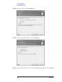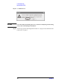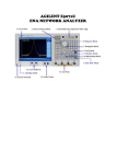
1
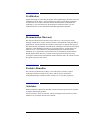
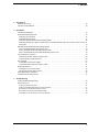
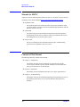
Caution
Do not exceed the operating input power, voltage, and current
level and signal type appropriate for the instrument being used, refer to
your instrument's Function Reference.
Electrostatic discharge(ESD) can damage the highly sensitive
microcircuits in your instrument. ESD damage is most likely to occur as
the test fixtures are being connected or disconnected. Protect them from
ESD damage by wearing a grounding strap that provides a high
resistance path to ground. Alternatively, ground yourself to discharge any
static charge built-up by touching the outer shell of any grounded
instrument chassis before touching the test port connectors.
Safety Summary
When you notice any of the unusual conditions listed below, immediately
terminate operation and disconnect the power cable.
Contact your local Agilent Technologies sales representative or
authorized service company for repair of the instrument. If you continue
to operate without repairing the instrument, there is a potential fire or
shock hazard for the operator.
- Instrument operates abnormally.
- Instrument emits abnormal noise, smell, smoke or a spark-like
light during operation.
- Instrument generates high temperature or electrical shock
during operation.
- Power cable, plug, or receptacle on instrument is damaged.
- Foreign substance or liquid has fallen into the instrument.
Herstellerbescheinigung

GERAUSCHEMISSION
LpA
< 70 dB
am Arbeitsplatz
normaler Betrieb
nach DIN 45635 T. 19
Manufacturer's Declaration
ACOUSTIC NOISE EMISSION
LpA
< 70 dB
operator position
normal operation
per ISO 7779
Regulatory compliance information
This product complies with the essential requirements of the following applicable European Directives, and
carries the CE marking accordingly:
The Low Voltage Directive 73/23/EEC, amended by 93/68/EEC
The EMC Directive 89/336/EEC, amended by 93/68/EEC
To obtain Declaration of Conformity, please contact your local Agilent Technologies sales office, agent or
distributor.
Safety notice supplement
・ This equipment complies with EN/IEC61010-1:2001.
・ This equipment is MEASUREMENT CATEGORY I (CAT I). Do not use for CAT II, III, or IV.
・ Do not connect the measuring terminals to mains.
・ This equipment is POLLUTION DEGREE 2, INDOOR USE product.
・ This equipment is tested with stand-alone condition or with the combination with the accessories supplied
by Agilent Technologies against the requirement of the standards described in the Declaration of
Conformity. If it is used as a system component, compliance of related regulations and safety requirements
are to be confirmed by the builder of the system.
Agilent E5071C ENA Series RF Network Analyzers
Installation Guide
First Edition
Manufacturing No. E5071-90000
October 2006
Notices
The information contained in this document is subject to change without notice.
This document contains proprietary information that is protected by copyright. All rights
are reserved. No part of this document may be photocopied, reproduced, or translated to
another language without the prior written consent of Agilent Technologies.
Microsoft®,MS-DOS®,Windows®,Visual C++®,Visual Basic®,VBA® and Excel® are
registered trademarks of Microsoft Corporation.
Java® is registered trademark of Sum Microsystems Corporation.
© Copyright 2006 Agilent Technologies
Manual Printing History
The manual’s printing date and part number indicate its current edition. The printing date
changes when a new edition is printed (minor corrections and updates that are incorporated
at reprint do not cause the date to change). The manual part number changes when
extensive technical changes are incorporated.
October 2006
2
First Edition
Safety Summary
The following general safety precautions must be observed during all phases of operation,
service, and repair of this instrument. Failure to comply with these precautions or with
specific WARNINGS elsewhere in this manual may impair the protection provided by the
equipment. Such noncompliance would also violate safety standards of design,
manufacture, and intended use of the instrument. Agilent Technologies assumes no liability
for the customer’s failure to comply with these precautions.
NOTE
The E5071C complies with INSTALLATION CATEGORY II as well as POLLUTION
DEGREE 2 in IEC61010-1. The E5071C is an INDOOR USE product.
NOTE
The LEDs in the E5071C are Class 1 in accordance with IEC60825-1,
CLASS 1 LED PRODUCT
•
Ground the Instrument
To avoid electric shock, the instrument chassis and cabinet must be grounded with the
supplied power cable’s grounding prong.
•
DO NOT Operate in an Explosive Atmosphere
Do not operate the instrument in the presence of inflammable gasses or fumes.
Operation of any electrical instrument in such an environment clearly constitutes a
safety hazard.
•
Keep Away from Live Circuits
Operators must not remove instrument covers. Component replacement and internal
adjustments must be made by qualified maintenance personnel. Do not replace
components with the power cable connected. Under certain conditions, dangerous
voltage levels may remain even after the power cable has been disconnected. To avoid
injuries, always disconnect the power and discharge circuits before touching them.
•
DO NOT Service or Adjust the Instrument Alone
Do not attempt internal service or adjustment unless another person, capable of
rendering first aid and resuscitation, is present.
•
DO NOT Substitute Parts or Modify the Instrument
To avoid the danger of introducing additional hazards, do not install substitute parts or
perform unauthorized modifications to the instrument. Return the instrument to an
Agilent Technologies Sales and Service Office for service and repair to ensure that
safety features are maintained in operational condition.
•
Dangerous Procedure Warnings
Warnings, such as the example below, precede potentially dangerous procedures
throughout this manual. Instructions contained in the warnings must be followed.
WARNING
Dangerous voltage levels, capable of causing death, are present in this instrument.
Use extreme caution when handling, testing, and adjusting this instrument.
3
Safety Symbols
General definitions of safety symbols used on the instrument or in manuals are listed
below.
Instruction Manual symbol: the product is marked with this symbol when it is necessary for
the user to refer to the instrument manual.
Alternating current.
Direct current.
On (Supply).
Off (Supply).
In-position of push-button switch.
Out-position of push-button switch.
A chassis terminal; a connection to the instrument’s chassis, which includes all exposed
metal structure.
Stand-by.
WARNING
This warning sign denotes a hazard. It calls attention to a procedure, practice, or
condition that, if not correctly performed or adhered to, could result in injury or
death to personnel.
CAUTION
This Caution sign denotes a hazard. It calls attention to a procedure, practice, or condition
that, if not correctly performed or adhered to, could result in damage to or destruction of
part or all of the instrument.
NOTE
This Note sign denotes important information. It calls attention to a procedure, practice, or
condition that is essential for the user to understand.
4
Certification
Agilent Technologies certifies that this product met its published specifications at the time
of shipment from the factory. Agilent Technologies further certifies that its calibration
measurements are traceable to the United States National Institute of Standards and
Technology, to the extent allowed by the Institution’s calibration facility or by the
calibration facilities of other International Standards Organization members.
Documentation Warranty
The material contained in this document is provided "as is," and is subject to being
changed, without notice, in future editions. Further, to the maximum extent permitted by
applicable law, Agilent disclaims all warranties, either express or implied with regard to
this manual and any information contained herein, including but not limited to the implied
warranties of merchantability and fitness for a particular purpose. Agilent shall not be
liable for errors or for incidental or consequential damages in connection with the
furnishing, use, or performance of this document or any information contained herein.
Should Agilent and the user have a separate written agreement with warranty terms
covering the material in this document that conflict with these terms, the warranty terms in
the separate agreement will control.
Exclusive Remedies
The remedies provided herein are Buyer’s sole and exclusive remedies. Agilent
Technologies shall not be liable for any direct, indirect, special, incidental, or
consequential damages, whether based on contract, tort, or any other legal theory.
Assistance
Product maintenance agreements and other customer assistance agreements are available
for Agilent Technologies products.
For any assistance, contact your nearest Agilent Technologies Sales and Service Office.
Addresses are provided at the back of this manual.
5
Typeface Conventions
Sample (bold)
Boldface type is used when a term is defined or
emphasized.
Sample (Italic)
Italic type is used for emphasis and for titles of
manuals and other publications.
Sample menu/button/box/tab
Indicates a menu/button/box/tab on the screen
labeled “Sample” which can be selected/executed
by clicking. “menu”, “button”, “box”, or “tab“
may be omitted.
[Sample]
Indicates the hardkey whose key label is
“Sample“.
[Sample] > Item
Indicates a series of key operations in which you
press the [Sample] key, make the item called
“Item” on the displayed menu blink by using the
[ ↓] or in other ways, and then press the [Enter]
key.
6
Contents
1. Introduction
Manuals for E5071C . . . . . . . . . . . . . . . . . . . . . . . . . . . . . . . . . . . . . . . . . . . . . . . . . . . . . . . . . . . . . . . . . . . 10
Contents of This Manual. . . . . . . . . . . . . . . . . . . . . . . . . . . . . . . . . . . . . . . . . . . . . . . . . . . . . . . . . . . . . . . . 10
2. Installation
Checking the Shipment . . . . . . . . . . . . . . . . . . . . . . . . . . . . . . . . . . . . . . . . . . . . . . . . . . . . . . . . . . . . . . . . . 13
Environmental Requirements . . . . . . . . . . . . . . . . . . . . . . . . . . . . . . . . . . . . . . . . . . . . . . . . . . . . . . . . . . . . 14
Operating Environments . . . . . . . . . . . . . . . . . . . . . . . . . . . . . . . . . . . . . . . . . . . . . . . . . . . . . . . . . . . . . . 14
Ventilation Requirements . . . . . . . . . . . . . . . . . . . . . . . . . . . . . . . . . . . . . . . . . . . . . . . . . . . . . . . . . . . . . 15
Protection Against Electrostatic Discharge (ESD) . . . . . . . . . . . . . . . . . . . . . . . . . . . . . . . . . . . . . . . . . . 16
Ensuring Adequate Free Space around Analyzer for Immediate Disconnection of Power Cable in Case of
Emergency. . . . . . . . . . . . . . . . . . . . . . . . . . . . . . . . . . . . . . . . . . . . . . . . . . . . . . . . . . . . . . . . . . . . . . . . . 16
Installing Front Handles/Rack Mounting Flanges . . . . . . . . . . . . . . . . . . . . . . . . . . . . . . . . . . . . . . . . . . . . 17
How to Install the Handle Kit (Option 1CN) . . . . . . . . . . . . . . . . . . . . . . . . . . . . . . . . . . . . . . . . . . . . . . 18
How to Install the Rack-mount Kit (Option 1CM) . . . . . . . . . . . . . . . . . . . . . . . . . . . . . . . . . . . . . . . . . . 19
How to Install the Rack-mount and Handle Kit (Option 1CP) . . . . . . . . . . . . . . . . . . . . . . . . . . . . . . . . . 19
Connecting the Accessaries . . . . . . . . . . . . . . . . . . . . . . . . . . . . . . . . . . . . . . . . . . . . . . . . . . . . . . . . . . . . . 20
Connecting the BNC Adaptor (Option 1E5) . . . . . . . . . . . . . . . . . . . . . . . . . . . . . . . . . . . . . . . . . . . . . . . 20
Connecting Mouse and Keyboard . . . . . . . . . . . . . . . . . . . . . . . . . . . . . . . . . . . . . . . . . . . . . . . . . . . . . . . 20
Power Supply . . . . . . . . . . . . . . . . . . . . . . . . . . . . . . . . . . . . . . . . . . . . . . . . . . . . . . . . . . . . . . . . . . . . . . . . 21
Verification of the Power Supply . . . . . . . . . . . . . . . . . . . . . . . . . . . . . . . . . . . . . . . . . . . . . . . . . . . . . . . 21
Verification and Connection of Power Cable . . . . . . . . . . . . . . . . . . . . . . . . . . . . . . . . . . . . . . . . . . . . . . 21
Starting the E5071C . . . . . . . . . . . . . . . . . . . . . . . . . . . . . . . . . . . . . . . . . . . . . . . . . . . . . . . . . . . . . . . . . . . 23
Turning the Power ON and OFF . . . . . . . . . . . . . . . . . . . . . . . . . . . . . . . . . . . . . . . . . . . . . . . . . . . . . . . . 23
Disconnection from Supply Source. . . . . . . . . . . . . . . . . . . . . . . . . . . . . . . . . . . . . . . . . . . . . . . . . . . . . . 24
Initial Registration of E5071C . . . . . . . . . . . . . . . . . . . . . . . . . . . . . . . . . . . . . . . . . . . . . . . . . . . . . . . . . . . 25
Calibration of the Touch Screen . . . . . . . . . . . . . . . . . . . . . . . . . . . . . . . . . . . . . . . . . . . . . . . . . . . . . . . . . . 27
3. Troubleshooting
Troubleshooting during Startup . . . . . . . . . . . . . . . . . . . . . . . . . . . . . . . . . . . . . . . . . . . . . . . . . . . . . . . . . . 30
System Recovery . . . . . . . . . . . . . . . . . . . . . . . . . . . . . . . . . . . . . . . . . . . . . . . . . . . . . . . . . . . . . . . . . . . . . 31
Types of system recoveries . . . . . . . . . . . . . . . . . . . . . . . . . . . . . . . . . . . . . . . . . . . . . . . . . . . . . . . . . . . . 31
Notes on executing the factory recovery function . . . . . . . . . . . . . . . . . . . . . . . . . . . . . . . . . . . . . . . . . . 31
Procedure to execute the factory recovery . . . . . . . . . . . . . . . . . . . . . . . . . . . . . . . . . . . . . . . . . . . . . . . . 32
Procedure to create the user backup image . . . . . . . . . . . . . . . . . . . . . . . . . . . . . . . . . . . . . . . . . . . . . . . . 34
Procedure to execute the user recovery function . . . . . . . . . . . . . . . . . . . . . . . . . . . . . . . . . . . . . . . . . . . 40
7
Contents
8
1. Introduction
1
Introduction
This chapter introduces the documentation for Agilent E5071C and the overview of this
manual to use this manual efficiently. See this manual first when you use the E5071C for
the first time.
9
Introduction
Manuals for E5071C
Manuals for E5071C
Agilent provides the following three manuals for E5071C. The latest version of all documentations can be downloaded from http://www.agilent.com/find/ena_support/.
R Installation Guide
The installaton guide (this manual) provides start up setup information when
you use the E5071C for the first time and troubleshooting information when the
Windows cannot be boot up.
R Online Help
The online help provides the information about the measurement operation,
programming, built-in VBA, I/O interface This is pre-installed in the E5071C.
Press [Help] hard key on the fron panel to open.
R Service Guide
The service manual provides information about the parts, troubleshooting,
performance test, adjustment and service menu.
Contents of This Manual
The following shows the contents of this manual.
R Chapter 1, “Introduction”
This chapter introduces the documentation for Agilent E5071C and the
overview of this manual to use this manual efficiently. See this manual first
when you use the E5071C for the first time.
R Chapter 2, “Installation”
This chapter provides information about how to set up the Agilent E5071C.
R Chapter 3, “Troubleshooting”
This chapter describes the troubleshooting during start up and the procesure of
the operating system (OS) recovery when the Windows XP OS has been
damaged.
10
Chapter 1
2. Installation
2
Installation
This chapter provides information about how to set up the Agilent E5071C.
11
Installation
Contents of this
Chapter
R Checking the Shipment on page 13
After you receive the analyzer, check all the items in the packing container.
R Environmental Requirements on page 14
Describes the system requirements needed to install the E5071C and how to
secure space for heat radiation.
R Installing Front Handles/Rack Mounting Flanges on page 17
Shows how to mount the front handles used to transport the E5071C and how to
install the flanges needed to install it in a rack.
R Connecting the Accessaries on page 20
Provides information for connecting the mouse, keyboard, BNC adaptor to the
E5071C.
R Power Supply on page 21
Shows how to check the power supply as well as check and connect the power
cable.
R Starting the E5071C on page 23
Describes turning on/off of the Power switch and cutting off the power supply.
R Initial Registration of E5071C on page 25
Provides the procedure of intitial registaration for the Windows XP operating
system of the E5071C.
R Calibration of the Touch Screen on page 27
Provides the procedure of touch screen calibration.
12
Chapter 2
Installation
Checking the Shipment
Checking the Shipment
After you receive the analyzer, carry out checks during unpacking according to the
following procedure.
WARNING
Step 1. Check that the packing box or shock-absorbing material used to package the analyzer has
not been damaged.
NOTE
If the packing box or shock-absorbing material has been damaged, leave the packing box
and shock-absorbing material as is until other inspection items are checked as follows:
Step 2. Check the packaged items supplied with the analyzer for any damage or defects.
Step 3. By referring to the furnished contents list, check that all packaged items supplied with the
analyzer have been provided as per the specified options.
Step 4. After checking, if one of the following applies, contact your nearest Agilent Technologies
sales and service office.
1. The packing box or shock-absorbing material used to package the analyzer has been
damaged or the shock-absorbing material has traces where extreme force has been
applied.
2. A packaged item supplied with the analyzer has mechanical damage or defects.
3. A packaged item supplied with the analyzer is missing.
4. A fault has been detected in the subsequent operation check of the analyzer.
If an abnormality is detected in step 1, contact the company that transported the analyzer as
well as your nearest Agilent Technologies sales and service office. For inspection by the
transport company, save the packing box, shock-absorbing material, and packaged items as
you received them.
Chapter 2
13
2. Installation
When unpacking the analyzer, if the external face of the analyzer (such as the cover,
front/rear panel, LCD screen, power switch, and port connectors) appear to be
damaged during transport, do not turn on the power switch. Otherwise, you may get
an electric shock.
Installation
Environmental Requirements
Environmental Requirements
Set up the E5071C where the following environmental requirements are met.
Operating Environments
Ensure that the operating environment meets the following requirements.
NOTE
Temperature
5 °C to 40 °C
Temperature range at the
error-correction
23 °C ± 5 °C (< 1 °C deviation from the temperature
when performing the error-correction)
Humidity
20% to 80% at wet bulb temperature < +29 °C
(non-condensation)
Altitude
0 to 2,000 m (0 to 6,561 feet)
Vibration
0.21 G maximum, 5 Hz to 500 Hz
Above environmental requirements are NOT for the specifications and measurement
accuracy of the analyzer, but for the operating environment of the analyzer.
14
Chapter 2
Installation
Environmental Requirements
Ventilation Requirements
To ensure safety requirements, the specifications and measurement accuracy of the
analyzer, you must keep environmental temperature within the specified range by
providing appropriate cooling clearance around the analyzer or, for the rackmount type, by
forcefully air-cooling inside the rack housing. For more information on environmental
temperature to satisfy the specifications and measurement accuracy of the analyzer, see the
specification in the E5071C Online Help.
Requirements
Figure 2-1
Back
≥ 180 mm
Sides
≥ 60 mm (both right and left)
Ventilation space at the installation
ACTIVE CH/TRACE
RESPONSE
ENTRY
NAVIGATION
OO
OO
Softkey On/Off
STIMULUS
MKR/ANALYSIS
INSTR STATE
Capture
PORT 1
PORT 2
PORT 3
PORT 4
USB
PROBE POWER
+ 26 dBm RF 35 VDC Max
Avoid Static Discharge CAT Σ
OO
e5071cqe1001
Chapter 2
15
2. Installation
When the environmental temperature around the analyzer is kept within the temperature
range of the operating environment specification (See Section “Operating Environments”
on page 14), the analyzer conforms to the requirements of the safety standard.
Furthermore, under that temperature requirement, the analyzer still conforms to the
requirements of the safety standard even when placing the analyzer with cooling clearance
as follows:
Installation
Environmental Requirements
Protection Against Electrostatic Discharge (ESD)
Set up a static-safe work-station to protect the electronic components from the damage by
the electrostatic discharge (ESD) as shown in Figure 2-2. Table 2-1 shows the accessories
available that provide ESD protection.
Table 2-1
The accessories available that provide ESD protection
Name
Figure 2-2
Agilent Part Number
Static-control table mat and earth ground wire
9300-0797
Wrist-strap cord
9300-0980
Wrist-strap
9300-1383
Heel-straps
9300-1169
Example of the static-safe work-station
Ensuring Adequate Free Space around Analyzer for Immediate
Disconnection of Power Cable in Case of Emergency
As described in “Disconnection from Supply Source” on page 24, the power supply is
disconnected by removing the power cable’s connector plug from either the AC outlet or
the E5071C unit. When installing the E5071C, ensure that there is sufficient free space
around the unit to permit quick disconnection of the plug (from AC outlet or E5071C unit)
in case of emergency.
16
Chapter 2
Installation
Installing Front Handles/Rack Mounting Flanges
Installing Front Handles/Rack Mounting Flanges
The E5071C can be installed on a workbench or in a rack. This section describes how to
install the front handles (Option 1CN) used for moving or transporting the instrument, and
how to install the analyzer in an equipment rack as part of a measurement system (Option
1CM: without the handles, Option 1CP: with the handles).
Table 2-2
Agilent E5071C handles/rack mounting options
Table 2-3
Name
Agilent Part Number
1CN
Handle Kit
5063-9229
1CM
Rack-mount Kit
5063-9216
1CP
Rack-mount and Handle Kit
5063-9223
Contents of each option
Option
1CN
1CM
1CP
Chapter 2
Contents
Quantity
Front Handles
2
Screws
6
Trim Strips
2
Rack-mounting flanges (locking side plate)
2
Screws
6
Rack-mounting flanges (locking side plate)
2
Front Handles
2
Screws
8
17
2. Installation
Option
Installation
Installing Front Handles/Rack Mounting Flanges
Figure 2-3
Installing front handle/rack-mount kits
How to Install the Handle Kit (Option 1CN)
The handle kit is used for transport and relocation of the E5071C. While referring to Figure
2-3, install the handle kit by following these steps.
Step 1. Remove the adhesive-backed trim strip (1) from each side of the outer frame of the
E5071C front panel.
Step 2. Use the provided screws to mount the front handles (2) on each side of the E5071C front
panel frame.
Step 3. Attach the provided modified trim strip (3) to each front handle in order to cover the front
panel locking screws.
WARNING
If the installed front handle becomes damaged, replace it with a new one immediately.
A damaged handle can break while moving or lifting the instrument and cause
personal injury or damage to the instrument.
18
Chapter 2
Installation
Installing Front Handles/Rack Mounting Flanges
How to Install the Rack-mount Kit (Option 1CM)
The rack-mount kit includes two flanges (locking side plates) for mounting the E5071C on
a rack (482.6 mm/19 inches) conforming to the EIA Standard. While referring to Figure
2-3, install the rack-mount kit by following these steps.
Step 1. Remove the adhesive-backed trim strip (1) from each side of the outer frame of the
E5071C front panel.
Step 2. Use the provided screws to mount a rack-mounting flange (4) on each side of the E5071C
front panel frame.
Step 4. Mount the E5071C on the rack.
How to Install the Rack-mount and Handle Kit (Option 1CP)
The rack-mount and handle kit includes both the rack-mounting flanges (locking side
plates) and front handles. While referring to Figure 2-3, install the rack-mount kit by
following these steps.
Step 1. Remove the adhesive-backed trim strip (1) from each side of the outer frame of the
E5071C front panel.
Step 2. Use the provided screws to mount a front handle (2) and rack-mounting flange (4) on each
side of the E5071C front panel frame.
CAUTION
Use both a front handle and a rack-mounting flange in the same time certainly. Do not
attempt to install flanges or handles separately with hardware provided. Serious electrical
damage will occur to the instrument.
Step 3. Remove the four bottom feet of the E5071C (lift the bar marked TAB on the inner side of
the foot and slide the foot toward the bar).
Step 4. Mount the E5071C on the rack.
Chapter 2
19
2. Installation
Step 3. Remove the four bottom feet of the E5071C (lift the bar marked TAB on the inner side of
the foot and slide the foot toward the bar).
Installation
Connecting the Accessaries
Connecting the Accessaries
You need to connect some accessaries before use.
Connecting the BNC Adaptor (Option 1E5)
When the E5071C is equipped with Option 1E5 (high-stability frequency standard),
connect the BNC adaptor from the Ref Oven terminal to the Ref In terminal on the rear
panel as shown in Figure 2-4. The BNC adaptor is included in Option 1E5. When Option
1E5 is installed, the frequency accuracy and stability of the E5071C will further improve.
Figure 2-4
Connecting the BNC adaptor
ICES/NMB-001
LR95111C
GPIB
4
EXT TRIG
IN
ISM 1-A
N10149
NOTE
24 BIT I/O
WARNING: No operator serviceable
parts inside. Refer servicing to qualified
personnel.
Switch must remain
ON while operating.
USB
EXT TRIG
OUT
115 V
50/60 Hz
- 230 V
350 VA Max
LINE
Model# Label
Serial Label
REF IN
REF OUT
10 MHz
AUX IN 2
AUX IN 1
1 V, 10 V
I/O PANEL
PRINTER
(PARALLEL)
RESERVED
ETHERNET
VIDEO
1
3
2
4
RESERVED
Windows Label
REF OVEN
(10 MHz)
BNC adaptor
PORT 4
FUSE 0.5 A
PORT 3
PORT 2
BIAS INPUT
35 VDC Max
PORT 1
e5071cqe1002
Connecting Mouse and Keyboard
E5071C allows you to connect Mouse and/or keyboard through USB or PS/2. USB mouse
and keyboard can be connected with the USB ports on the front or rear panels.
Initial registration of the E5071C requires the mouse and the keyboard before turning on
the power.
20
Chapter 2
Installation
Power Supply
Power Supply
Before turning on the E5071C power, check the following.
Verification of the Power Supply
Confirm that the power supplied to the E5071C meets the following requirements:
Voltage
90 to 132 VAC or 198 to 264 VAC *1
Frequency
47 to 63 Hz
Maximum power consumption
350 VA
2. Installation
Requirements
*1. Switched automatically by the E5071C in conformity to the voltage used.
Verification and Connection of Power Cable
The three-wire power cable attached to the E5071C has one wire serving as a ground.
Using this power cable allows the E5071C to be grounded, thereby protecting you against
electrical shock from the power outlet.
Step 1. Confirm that the power cable is not damaged.
WARNING
NEVER use a power cable showing any sign of damage. Faulty cables can cause
electrical shock.
Step 2. Use the supplied cable to connect between the power cable receptacle (Figure 2-6 on
page 24) on the rear panel of the E5071C and a three-wire power outlet with the grounding
prong firmly connected in the ground slot.
WARNING
Use the supplied power cable with grounding wire to securely ground the E5071C.
Figure 2-5 shows the power cable options.
Chapter 2
21
Installation
Power Supply
Figure 2-5
Power cable options
22
Chapter 2
Installation
Starting the E5071C
Starting the E5071C
This section describes how to turn on/off the E5071C power and how to cut off the power
supply in an emergency.
Turning the Power ON and OFF
Perform the following steps to turn the power ON or OFF.
Step 1. Confirm if the Line Switch on the rear panel is on. The switch should always be turned on.
Step 2. If the standby switch (
(
) in the lower-left part of the front panel is in the depressed
) position, press it to put it in the popped up position (
Step 3. Press the standby switch to put it in the depressed position (
).
).
This operation turns ON the power, and the E5071C starts the self-test.
Step 4. Confirm that the self-test indicates normal operation.
Normal operation is confirmed by the self-test if no error message appears.
Turning the Power OFF
Step 1. Use either of the following methods to turn the power OFF.
•
Press the standby switch (
pressed down (
•
) in the lower-left part of the front panel (now in the
) position) to put it in the popped up (
) position.
Click Turn off Computer from Windows Start menu
These operations will start the E5071C shutdown process (required software and hardware
processes for turning the power off), and the power will turn OFF after a few seconds.
NOTE
Under normal circumstances, always press the standby switch ( ), or click Turn off
Computer from Windows Start menu, to execute the E5071C shutdown process. Never cut
off the power supply directly by disconnecting the power cable plug from the rear
panel of the unit.
If the power supply is cut off directly by disconnecting the power cable plug from the
instrument or the AC outlet, the shutdown process is not carried out and there is a risk of
damage to the E5071C’s software or hardware.
Chapter 2
23
2. Installation
Turning the Power ON
Installation
Starting the E5071C
Figure 2-6
Line switch (Always ON) and power cable receptacle
Power Cable Receptacle
Line Switch: Always ON ( | )
ICES/NMB-001
LR95111C
GPIB
4
EXT TRIG
IN
ISM 1-A
N10149
NOTE
24 BIT I/O
WARNING: No operator serviceable
parts inside. Refer servicing to qualified
personnel.
Switch must remain
ON while operating.
USB
EXT TRIG
OUT
115 V
50/60 Hz
- 230 V
350 VA Max
LINE
Model# Label
Serial Label
REF IN
REF OUT
10 MHz
AUX IN 2
AUX IN 1
1 V, 10 V
I/O PANEL
PRINTER
(PARALLEL)
RESERVED
ETHERNET
VIDEO
1
3
2
4
RESERVED
Windows Label
REF OVEN
(10 MHz)
PORT 4
FUSE 0.5 A
PORT 3
PORT 2
BIAS INPUT
35 VDC Max
PORT 1
e5071cqe1003
Disconnection from Supply Source
The power supply of the E5071C is cut off by disconnecting the plug of the power cable
(on either AC outlet side or E5071C side). When it is necessary to disconnect the power
supply in order to avoid shock hazards, etc., pull out the power cable plug from either the
AC outlet side or the E5071C side.
NOTE
To allow this operation to be performed smoothly, be sure to follow the guidelines in
“Ensuring Adequate Free Space around Analyzer for Immediate Disconnection of Power
Cable in Case of Emergency” on page 16.
When turning the power OFF under normal circumstances, always follow the methods
described in “Turning the Power OFF” on page 23.
24
Chapter 2
Installation
Initial Registration of E5071C
Initial Registration of E5071C
When you start up the E5071C at the first time, you need to perform the initial registration
of the Windows XP operating system of the E5071C.
You cannot use the front panel keys during the initial registration of the E5071C therefore
connect the mouse and the keyboard before turning on the power.
NOTE
If you perform the following procedure incorrectly, a message asking you whether to return
to the previous registration screen and perform the registration appears. In this case, follow
the instruction to return to the previous registration screen.
Step 1. Turns on the E5071C.
Step 2. The Windows XP Professional Setup wizard appears. Click the Next > button (Figure 2-7).
Figure 2-7
Windows XP Professional Setup wizard
e5071cse1073
Chapter 2
25
2. Installation
NOTE
Installation
Initial Registration of E5071C
Step 3. In the Windows XP Professional Setup dialog box, select the I accept this agreement box
and click the Next > button (Figure 2-8).
Figure 2-8
Windows XP Professional Setup dialog box (1/2)
e5071cse1074
Step 4. In the next dialog box , input agena in the Name box. Then, click the Next> button (Figure
2-9).
Figure 2-9
Windows XP Professional Setup dialog box (2/2)
e5071cse1075
Step 5. After a while, the E5071C restart automatically. Then, the measurement display appears.
26
Chapter 2
Installation
Calibration of the Touch Screen
Calibration of the Touch Screen
After E5071C measurement screen appears, you have to calibrate the touch screen. Follow
the procedure described below to calibrate the touch screen.
Step 1. Press
.
Step 2. Press Service Menu.
2. Installation
Step 3. Press Test Menu.
Step 4. Press Adjust Touch Screen.
The touch screen calibration screen (Figure 2-10) appears.
Figure 2-10
Touch Panel Calibration Screen
e5071cse1078
Step 5. Touch the x mark on the upper left with your finger. The mark x appears also on the upper
right, lower left, and lower right. Touch the x marks in that order with your finger.
Touching the four locations described above with your finger automatically concludes the
touch screen calibration.
NOTE
With no operation on the touch screen calibration screen for a preset time, it automatically
closes and the previous measurement screen reappears.
Chapter 2
27
Installation
Calibration of the Touch Screen
28
Chapter 2
1. Chapter 1
2. Chapter 2
3. Troubleshooting
3
Troubleshooting
5. Chapter 5
This chapter describes the troubleshooting during start up and the procesure of the
operating system (OS) recovery when the Windows XP OS has been damaged.
29
Troubleshooting
Troubleshooting during Startup
Troubleshooting during Startup
When you encounter the problem during start up, see Table 3-1. System recovery saves
most of problems.
Table 3-1
Troubleshooting during startup
Symptom
Solution
Turning on (|) the standby switch does not
start up the system.
Confirm that the power cable is properly
plugged in.
Confirm that the line switch on the rear
panel is turned on
The system starts up, but it automatically
shuts down immediately.
Execute the system recovery.
The system starts up, but it enters the
service mode (The instrument status bar
in the lower right part of the screen
displays SVC in red).
The measurement screen appears after
startup, but the power-on test is failed,
with Error Message 241 appearing against
a red background in the instrument
message/warning area in the lower left
part of the screen.
30
Chapter 3
1. Chapter 1
Troubleshooting
System Recovery
System Recovery
By executing system recovery, you can return the system of the E5071C (the Windows
operating system and the firmware) to the factory state (at the time of purchase*1).
2. Chapter 2
Types of system recoveries
The following 2 types of system recoveries are available.
R Factory recovery
Returns the contents of the C and D drives to the factory state.
R User recovery
Returns the contents of the C and D drives to a user-specified state. To use this
function, you must prepare for recovery in advance. For information on the
preparation, see “Procedure to create the user backup image” on page 34 for
information on the execution, see “Procedure to execute the user recovery function” on
page 40.
Executing the factory recovery function causes the following conditions:
R In addition to the Windows operating system and the firmware, the following settings
of the E5071C are returned to the factory state.
•
•
•
Network setting
GPIB setting
Printer setting
3. Troubleshooting
Notes on executing the factory recovery function
R The driver for the supported printer installed after purchase is deleted.
Files you created using the save function (files in the D drive) are not affected, but we
recommend backing them up before executing system recovery for precautionary
purposes. For more information on backup, refer to “Backing Up the Data” as described in
E5071C Online Help.
4. Chapter 4
R You need to execute initial registration again.
5. Chapter 5
*1.If the hard disk failed and has been replaced after purchase, the state when the replacement
was performed is recovered.
Chapter 3
31
Troubleshooting
System Recovery
Procedure to execute the factory recovery
This section describes how to return the contents of the C and D drives to the factory state.
NOTE
You need a keyboard and mouse for this operation.
Step 1. Shut down the E5071C.
Step 2. Connect the keyboard and mouse to the E5071C.
Step 3. Press the standby switch of the E5071C to turn it on.
Step 4. When the screen as shown in the figure below appears, press
F11
of the keyboard.
Starting Acronis Loader...
Press F11 for Acronis Startup Recovery Manager...
e5071cse1055
NOTE
After several seconds, the next screen appears automatically even if you do not press any
key, so do not miss it.
Step 5. Click Restore.
Figure 3-1
Activate Acronis Startup Recovery Manager
e5071cse1079
Step 6. A confirmation dialog box is displayed. Click Yes to start the recovery of the factory
backup. The recovery takes a few minutes depending on the amount of data.
32
Chapter 3
Figure 3-2
Recover Factory Backup
1. Chapter 1
Troubleshooting
System Recovery
2. Chapter 2
e5071cse1034
Step 7. When the recovery is finished, click OK. The E5071C restarts automatically.
Step 8. After restart, the screen for initial registration appears. Execute initial registration. For
information on the execution procedure, refer to “Initial Registration of E5071C” on
page 25.
CAUTION
Never turn off the power during the system recovery because doing so may cause
serious damage to the E5071C.
3. Troubleshooting
Step 9. Execute the calibration of the touch screen. For information on the execution procedure,
refer to “Calibration of the Touch Screen” on page 27.
4. Chapter 4
5. Chapter 5
Chapter 3
33
Troubleshooting
System Recovery
Procedure to create the user backup image
This section describes how to create the user backup image. The C and D drives’ contents
saved in this procedure are recalled when the user recovery function is executed.
Step 1. Close the E5071C application by pressing System > Service Menu > Exit.
Step 2. Close all other applications you currently open.
Step 3. From the Windows start menu, select All Programs > Acronis > Acronis True Image.
Step 4. Click “No, Thanks” button.
Figure 3-3
Recover User Backup
e5071cse1080
Step 5. Click Backup
e5071cse1125
34
Chapter 3
Step 6. Click Next button.
1. Chapter 1
Troubleshooting
System Recovery
2. Chapter 2
3. Troubleshooting
e5071cse1126
Step 7. Select “The entire disk contents or individual partition,” then click Next button.
4. Chapter 4
5. Chapter 5
e5071cse1127
Chapter 3
35
Troubleshooting
System Recovery
Step 8. Select the C drive and D drive.
e5071cse1128
Step 9. Select the destination folder and input a file name, then click Next button. It is
recommended to save the file to a directory which has enough space like the E drive. Also,
never save the contents of the drive to the C, D or F drive.
e5071cse1129
36
Chapter 3
Step 10. Select “Set the options manually” and click Next button.
1. Chapter 1
Troubleshooting
System Recovery
2. Chapter 2
3. Troubleshooting
e5071cse1130
Step 11. Select “Backup priority” in the left field and “High” in the right field, then click Next
button.
4. Chapter 4
5. Chapter 5
e5071cse1131
Chapter 3
37
Troubleshooting
System Recovery
Step 12. If necessary, input comments and click Next button. The comments can be omitted.
e5071cse1132
Step 13. Click Proceed button.
e5071cse1133
38
Chapter 3
Step 14. The following screen appears during backup.
1. Chapter 1
Troubleshooting
System Recovery
2. Chapter 2
3. Troubleshooting
e5071cse1134
Step 15. The following screen appears when the user backup image was created. Click OK.
4. Chapter 4
e5071cse1135
CAUTION
Never turn off the power during creating the user backup image because doing so
may cause serious damage to the E5071C.
5. Chapter 5
Chapter 3
39
Troubleshooting
System Recovery
Procedure to execute the user recovery function
Returns the contents of the C and D drives to a user-specified state. To use this function,
you must create the user backup image in advance. For more information, see the
description “Procedure to create the user backup image” on page 34.
Step 1. Close the E5071C application by pressing System > Service Menu > Exit.
Step 2. Close all other applications you currently open.
Step 3. From the Windows start menu, select All Programs > Acronis > Acronis True Image.
Step 4. Click “No, Thanks” button.
e5071cse1080
Step 5. Click Recovery.
e5071cse1136
40
Chapter 3
Step 6. Click Next button.
1. Chapter 1
Troubleshooting
System Recovery
2. Chapter 2
3. Troubleshooting
e5071cse1137
Step 7. Select the saved backup image file, then click Next button.
4. Chapter 4
5. Chapter 5
e5071cse1138
Chapter 3
41
Troubleshooting
System Recovery
Step 8. Select “Restore disks or partitions,” then click Next button.
e5071cse1139
Step 9. Select the C drive, then click Next button.
e5071cse1143
42
Chapter 3
Step 10. Select the C drive to restore, then click Next button.
1. Chapter 1
Troubleshooting
System Recovery
2. Chapter 2
3. Troubleshooting
e5071cse1144
Step 11. Select “Active” and click Next button.
4. Chapter 4
5. Chapter 5
e5071cse1145
Chapter 3
43
Troubleshooting
System Recovery
Step 12. Click Next button.
e5071cse1146
Step 13. Select “Yes, I want to assign a logical drive letter to the restored partition” and click Next
button.
e5071cse1147
44
Chapter 3
Step 14. Select “Yes, I want to restore another partition or hard disk drive,” then click Next button.
1. Chapter 1
Troubleshooting
System Recovery
2. Chapter 2
3. Troubleshooting
e5071cse1148
Step 15. Select the D drive to restore, then click Next button.
4. Chapter 4
5. Chapter 5
e5071cse1149
Chapter 3
45
Troubleshooting
System Recovery
Step 16. Select the D drive to restore, then click Next button.
e5071cse1150
Step 17. Select “Logical” and click Next button.
e5071cse1151
46
Chapter 3
Step 18. Click Next button.
1. Chapter 1
Troubleshooting
System Recovery
2. Chapter 2
Step 19. Select “Yes, I want to assign a logical drive letter to the restored partition,” then click Next
button.
3. Troubleshooting
e5071cse1152
4. Chapter 4
5. Chapter 5
e5071cse1153
Chapter 3
47
Troubleshooting
System Recovery
Step 20. Select “No, I do not.” and click Next button.
e5071cse1154
Step 21. Select “Set the options manually” and click Next button.
e5071cse1155
Step 22. Select “Restoration Priority” in the left field and “High” in the right field, then click Next
48
Chapter 3
button.
1. Chapter 1
Troubleshooting
System Recovery
2. Chapter 2
3. Troubleshooting
e5071cse1156
Step 23. Click Proceed button.
4. Chapter 4
5. Chapter 5
e5071cse1157
Chapter 3
49
Troubleshooting
System Recovery
Step 24. Click Reboot button.
e5071cse1158
CAUTION
Never turn off the power during the recovery of the user backup image because doing
so may cause serious damage to the E5071C.
Step 25. After boot up, perform “Initial Registration of E5071C” on page 25 and “Calibration of the
Touch Screen” on page 27.
50
Chapter 3